vibration induced phase noise in quartz oscillators
TRANSCRIPT

Vibration Induced Phase Noise in Quartz Oscillators
www.ctscorp.com
Technical Paper

2 www.ctscorp.com
OVERVIEW
One of the most critical factors concerning modern applications, such as radar acquisition or communication systems, is phase noise. Phase noise is defined as the noise arising from the rapid, short term random phase fluctuations in a signal. It is an undesirable noise characteristic that appears on the output signal of an oscillator and can affect a radar system’s capability to accurately acquire a target or affect the spectral integrity within a communication system.
Many papers and publications in the public domain discuss phase noise, its effect on applications, and measure-ment techniques. What is often missed, and what this paper addresses, are the effects of mechanical acceleration (vibration) on the output signal noise of quartz-based oscillators. Unfortunately, even the lowest noise oscillators are affected by these mechanical accelerations. Typical examples may include the random vibration within an aircraft fuselage or simple sinusoidal vibration of a cooling fan mounted in a telecommunication equipment rack.
THEORY
When a quartz oscillator is exposed to an external accelerating force, strains within the quartz resonator result in frequency change as a function of that acceleration. These frequency changes are generally linear. The magnitude of the acceleration-induced frequency shift is proportional to the magnitude of the acceleration force, but also depends on the direction of the acceleration as well as the acceleration-sensitivity of the oscillator.
Such linear frequency change can become nonlinear at high accelerations due to deformation of the quartz resonator’s mounting structure. When exposed to time varying acceleration (sinusoidal), the strains within the quartz resonator cause time dependent frequency changes and result in frequency modulation.
2-G TIPOVER
Static gravitational force (G force) is a unit of constant acceleration with a magnitude of 1g (one gravity) im-parted on an object at the earth’s surface. When an oscillator is rotated 180° in an axis relative to the plane normal to the earth’s surface, the scalar product of the gravitational field of the oscillator changes from -1g to +1g. There is an effective 2g change in the acceleration force imparted upon the quartz resonator by virtue of “tipping over” the oscillator. The frequency change due to this 180° rotation, or 2g change, can be measured and will yield a discrete frequency change (Δf/f). The measured 2g frequency change, when divided by two, yields a “per g” frequency sensitivity and defines the “g-sensitivity,”, or “acceleration-sensitivity” of that particular axis.
Figure 1. Frequency change vs. Acceleration
3
This tip-over test is then repeated in the other mutually perpendicular axes. The axis with the highest resultant frequency change then defines the static, worst axis g-sensitivity for that particular device, also referred to its “static” g-sensitivity. This test is the standard 2-g tip-over test used across the oscillator industry to characterize and define g-sensitivity.
SINUSOIDAL VIBRATION
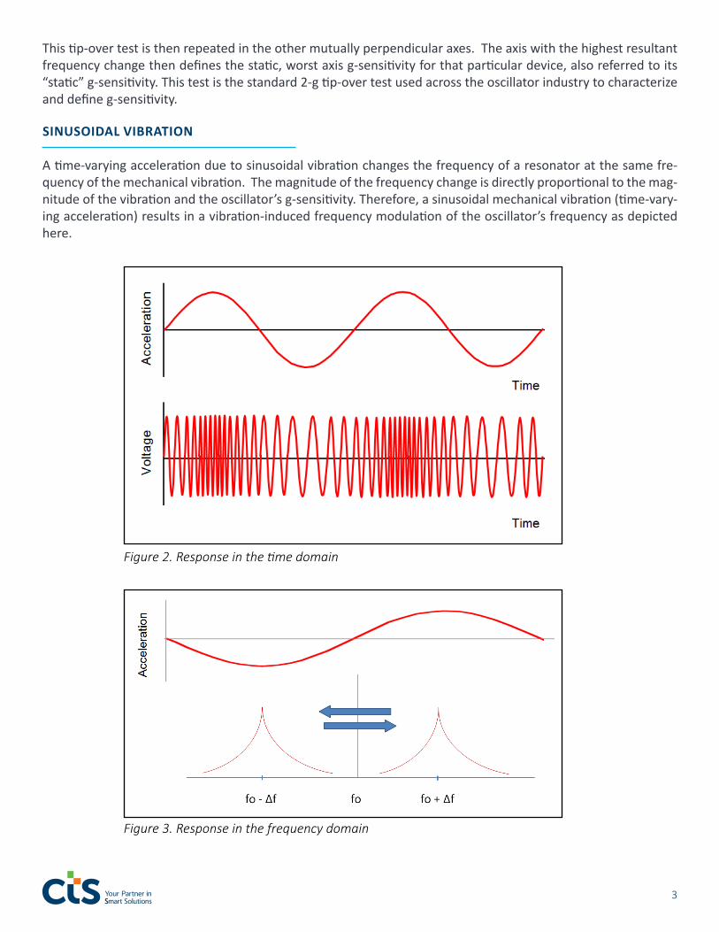
A time-varying acceleration due to sinusoidal vibration changes the frequency of a resonator at the same fre-quency of the mechanical vibration. The magnitude of the frequency change is directly proportional to the mag-nitude of the vibration and the oscillator’s g-sensitivity. Therefore, a sinusoidal mechanical vibration (time-vary-ing acceleration) results in a vibration-induced frequency modulation of the oscillator’s frequency as depicted here.
Figure 3. Response in the frequency domain
Figure 2. Response in the time domain

4 www.ctscorp.com
VIBRATION-INDUCED SIDEBANDS
Under an ideal sine wave vibration, spectral lines at the vibration frequency fV appear on either side of the carrier at ±fV points on the frequency spectrum. These spectral lines appear as sidebands in the phase noise spectrum and whose level, relative to the carrier, is defined by:
Where fv = vibration frequency, Γ = acceleration-sensitivity (or g-sensitivity) of the crystal, fo = oscillator carrier frequency, and A = the amplitude of the vibration in g’s.
As an example, consider a 200Mhz oscillator with acceleration sensitivity Γ = 1x10⁻⁹/g vibrated with a 100Hz sinusoid with an acceleration amplitude A = 1g. In this case, there will be resultant sidebands of -60 dBc at ±100 Hz from the carrier, as shown below.
There is very little energy in the pair of sideband spectral lines when compared to the power present in the car-rier. However, when viewed on a spectrum analyzer, the pair appears to have significant spectral density due to the spectrum analyzer’s finite bandwidth.
RANDOM VIBRATION-INDUCED PHASE NOISE
There are times when a quartz oscillator will be exposed to random vibration, a broad, random spectrum of simultaneous vibration forces at different frequencies and varying magnitudes (re. in the case of an airborne or mobile vehicular application). This spectrum of vibrating excitation is defined in Power Spectral Density (PSD) units, g2/Hz. In such cases, the entire phase noise spectrum degrades over the frequency range of the random vibration. For cases like this, random vibration contribution to phase noise is given by:
Figure 4. Sidebands at ±100 Hz due to sinusoidal vibration
( )L(f) = 20 log Γ x Af0
2fv
5
For the case where a quartz oscillator that has an acceleration sensitivity, Γ = 1x10⁻⁹/g and fo = 10 MHz, the phase “noise”; i.e., spectral lines, due solely to a vibration power spectral density, PSD = 0.1 g2/Hz will be:
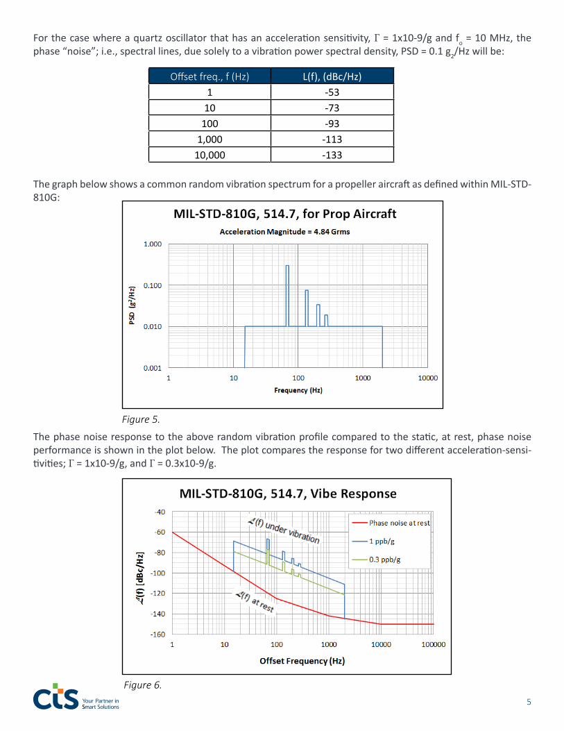
The graph below shows a common random vibration spectrum for a propeller aircraft as defined within MIL-STD-810G:
The phase noise response to the above random vibration profile compared to the static, at rest, phase noise performance is shown in the plot below. The plot compares the response for two different acceleration-sensi-tivities; Γ = 1x10⁻⁹/g, and Γ = 0.3x10⁻⁹/g.
Figure 5.
Figure 6.
Offset freq., f (Hz) L(f), (dBc/Hz)1 -53
10 -73100 -93
1,000 -11310,000 -133

6 www.ctscorp.com
This plot highlights the difference in vibration response levels for different levels of g-sensitivity. Even though a 0.3 ppb/g part yields 10 dB lower phase noise response than 1 ppb/g, it still rises significantly above the baseline, “at rest” noise level. Please note that regardless of the “at rest” phase noise level of a given quartz oscillator, under vibration conditions, such a device will result in the exact same phase noise degradation as any other oscillator given the same g-sensitivity. That means that an oscillator’s phase noise “at rest” could be 15 dB lower than that depicted in the plot above and will still exhibit the same noise levels across the vibration spectrum as shown.
MECHANICAL RESONANCES AND Q FACTOR
It should be noted that quartz-based oscillators and the sealed crystals utilized within are themselves mechanical structures and prone to mechanical resonances at fairly low frequencies. For instance, a standard two-point mounted crystal depicted below may have a resonance in the range of 400 to 1000 Hz defined by the moment-arm and thick-ness of the mounting support itself. A mechanical vibration at the resonant frequency will significantly magnify the effective g-sensitivity at that frequency (Q factor for that resonance). In the case of a typical 3 or 4 point crystal mount assembly (T08), the crystal mounts are much shorter, and resonances are generally greater than 2500 Hz.
For a 100 MHz crystal with a static g-sensitivity of 2 ppb/g and a mechanical resonance at 500 Hz, in which the Q of the resonance is 10 (meaning an effective 10x g-sensitivity at 500 Hz, or 20 ppb/g), the sideband that appears on the output spectrum will be -54 dBc below the carrier. If no mechanical resonance is present, the sideband would have been -74 dBc (refer to Eq. 1).
SUMMARY
This paper has discussed acceleration sensitivity within quartz-based crystal oscillators and has shown examples that demonstrate the impact of mechanical vibrations on their phase noise performance. Such mechanical vibrations cause degradation in signal noise level directly proportional to the vibration level and the g-sensitivity of each particular oscillator. Time-varying, sinusoidal vibrations produce degradation in the form of discrete sidebands, while random vibrations degrade phase noise across the entire spectrum of the vibration excitation. This document highlights and emphasizes the challenges and subsequent design considerations that should be weighed when integrating a quartz-based crystal oscillator into applications that may be exposed to vibration conditions.
Figure 7.

7
CTS OCXO MODELS THAT CAN ACHIEVE LOW G-SENSITIVITIES
CTS offers several OCXO models that can achieve g-sensitivities as low as 0.3 ppb/g; models: 122, VFOV141,V-FOV415, and VFOV514.
Model pkg(mm)
Freq(MHz)
Stability vs. Temp
(ppb)
Output Waveform
Aging per 10 years(ppm)
G-sensitivity(ppb/g) Feature
VFOV414 22 x 15 x 9.5TH or SMD 5-300 ±5 HCMOS or
Sine <0.5 1.0 std0.3 capable Ultra low power
VFOV415 16 x 15 x 9.5TH or SMD 5-100 ±5 HCMOS <0.5 1.0 std
0.3 capableUltra low power
1/2 DIP pkg
VFOV514 22 x 15 x 9.5TH or SMD 5-300 ±5 HCMOS or
Sine <0.5 1.0 std0.3 capable
Ultra low powerSMD
12220 x 20 x 13
thru hole 8-100±0.2±0.5 HCMOS or
Sine <0.5 1.0 std0.3 capable
Low aging and ADEV
When considering quartz-based crystal os-cillators with lower sensitivities to vibrations, mechanical suspensions and vibration isola-tion techniques are utilized/implemented within specific oscillator product families to isolate such devices from vibration condi-tions and reduce the impact on phase noise degradation.
CTS offers designers a phase noise under vibration evaluation tool to analyze the-oretical phase noise degradation when exposing a given oscillator to such condi-tions. The tool can be found on the CTS website at https://www.ctscorp.com/re-source-center/tutorials/.
AUTHOR
Jeff McCrackenApplications EngineerE-mail: [email protected]: +1 630-577-8816
Figure 8. Model VFOV414 Acceleration Sensitivity vs. Vibration

8 www.ctscorp.com
CTS Corporation – Your Partner in Smart Solutions
We’ve been part of the future for 125 years.
Founded in 1896, CTS Corporation (NYSE: CTS) is a leading designer and manufacturer of products that Sense, Connect, and Move.
CTS manufactures sensors, actuators, and electronic components in North America, Europe, and Asia. They provide solutions to OEMs in the aerospace, communications, defense, industrial, infor-mation technology, medical, and transportation markets.
CTS focuses on providing advanced technology, exceptional customer service, and superior value to industry partners throughout the globe.
CTS aims to be at the forefront of technology, delivering innovative sensing, connectivity and mo-tion solutions for the creation and advancement of products and services around the world.
ENGINEERING CONSULTATION
CTS provides complimentary consultations with one of our specialized design engineers to assist you in de-signing your embedded technology-based product or system.
Picking the right frequency control component is critical for success. Comparing hundreds of available fre-quency control components is time consuming. Consult a CTS engineer to save time in evaluating the right component for your project.
Leverage our engineering expertise. We encourage you to tap into our engineers’ collective knowledge base to solve your most complex design issues and find the best solution to meet your needs, no matter the appli-cation.
With a comprehensive portfolio of frequency control components, our engineers have a vast foundation of solutions to meet your requirements. However, if you need turnkey product development or a custom con-figuration to fit a specific application, our engineers are available to consult with you on how CTS can fulfill custom modifications to your meet your project specifications.
Choose how you request a consultation:
WEB FORM EMAIL

www.ctscorp.com
Contact CTS Corporation 4925 Indiana AvenueLisle, IL 60532Web: www.ctscorp.com
Author and Technical Contact:Jeff McCrackenApplications EngineerE-mail: [email protected]: +1 630-577-8816
Media Relations Contact:E-mail: [email protected]: +1 (630) 577-8865
Inquires:Technical Inquiry: https://www.ctscorp.com/contact/request-technical-info/ Sales Inquiry: https://www.ctscorp.com/contact/sample-request/
Technical Paper