version 1 - bitgravityasrock.pc.cdn.bitgravity.com/manual/fatal1ty x370 gaming-itxac.pdf · version...
TRANSCRIPT


Version 1.0 Published June 2017 Copyright©2017 ASRock INC. All rights reserved.
Copyright Notice:No part of this documentation may be reproduced, transcribed, transmitted, or translated in any language, in any form or by any means, except duplication of documentation by the purchaser for backup purpose, without written consent of ASRock Inc.
Products and corporate names appearing in this documentation may or may not be registered trademarks or copyrights of their respective companies, and are used only for identification or explanation and to the owners’ benefit, without intent to infringe.
Disclaimer:Specifications and information contained in this documentation are furnished for informational use only and subject to change without notice, and should not be constructed as a commitment by ASRock. ASRock assumes no responsibility for any errors or omissions that may appear in this documentation.
With respect to the contents of this documentation, ASRock does not provide warranty of any kind, either expressed or implied, including but not limited to the implied warranties or conditions of merchantability or fitness for a particular purpose.
In no event shall ASRock, its directors, officers, employees, or agents be liable for any indirect, special, incidental, or consequential damages (including damages for loss of profits, loss of business, loss of data, interruption of business and the like), even if ASRock has been advised of the possibility of such damages arising from any defect or error in the documentation or product.
This device complies with Part 15 of the FCC Rules. Operation is subject to the following two conditions: (1) this device may not cause harmful interference, and (2) this device must accept any interference received, including interference that
may cause undesired operation.
CALIFORNIA, USA ONLYThe Lithium battery adopted on this motherboard contains Perchlorate, a toxic substance controlled in Perchlorate Best Management Practices (BMP) regulations passed by the California Legislature. When you discard the Lithium battery in California, USA, please follow the related regulations in advance.“Perchlorate Material-special handling may apply, see www.dtsc.ca.gov/hazardouswaste/perchlorate”
ASRock Website: http://www.asrock.com

AUSTRALIA ONLYOur goods come with guarantees that cannot be excluded under the Australian Consumer Law. You are entitled to a replacement or refund for a major failure and compensation for any other reasonably foreseeable loss or damage caused by our goods. You are also entitled to have the goods repaired or replaced if the goods fail to be of acceptable quality and the failure does not amount to a major failure. If you require assistance please call ASRock Tel : +886-2-28965588 ext.123 (Standard International call charges apply)
The terms HDMI™ and HDMI High-Definition Multimedia Interface, and the HDMI logo are trademarks or registered trademarks of HDMI Licensing LLC in the United States and other countries.

Who knew that at age 19, I would be a World Champion PC gamer. When I was 13, I actually played competitive billiards in professional tournaments and won four or five games off guys who played at the highest level. I actually thought of making a career of it, but at that young age situations change rapidly. Because I’ve been blessed with great hand-eye coordination and a grasp of mathematics (an important element in video gaming) I gravitated to that activity.
GOING PROI started professional gaming in 1999 when I entered the CPL (Cyberathlete Professional League) tournament in Dallas and won $4,000 for coming in third place. Emerging as one of the top players in the United States, a company interested in sponsoring me flew me to Sweden to compete against the top 12 players in the world. I won 18 straight games, lost none, and took first place, becoming the number one ranked Quake III player in the world in the process. Two months later I followed that success by traveling to Dallas and defending my title as the world’s best Quake III player, winning the $40,000 grand prize. From there I entered competitions all over the world, including Singapore, Korea, Germany, Australia, Holland and Brazil in addition to Los Angeles, New York and St. Louis.
WINNING STREAKI was excited to showcase my true gaming skills when defending my title as CPL Champion of the year at the CPL Winter 2001 because I would be competing in a totally different first person shooter (fps) game, Alien vs. Predator II. I won that competition and walked away with a new car. The next year I won the same title playing Unreal Tournament 2003, becoming the only three-time CPL champion of the year. And I did it playing a different game each year, something no one else has ever done and a feat of which I am extremely proud.
At QuakeCon 2002, I faced off against my rival ZeRo4 in one of the most highly anticipated matches of the year, winning in a 14 to (-1) killer victory. Competing at Quakecon 2004, I became the World’s 1st Doom3 Champion by defeating Daler in a series of very challenging matches and earning $25,000 for the victory.
Since then Fatal1ty has traveled the globe to compete against the best in the world, winning prizes and acclaim, including the 2005 CPL World Tour Championship in New York City for a $150,000 first place triumph. In August 2007, Johnathan was awarded the first ever Lifetime Achievement Award in the four year history of the eSports-Award for “showing exceptional sportsmanship, taking part in shaping eSports into what it is today and for being the prime representative of this young sport. He has become the figurehead for eSports worldwide”.
Fatal1ty Story

LIVIN’ LARGESince my first big tournament wins, I have been a “Professional Cyberathlete”, traveling the world and livin’ large with lots of International media coverage on outlets such as MTV, ESPN and a 60 Minutes segment on CBS to name only a few. It's unreal - it's crazy. I’m living a dream by playing video games for a living. I’ve always been athletic and took sports like hockey and football very seriously, working out and training hard. This discipline helps me become a better gamer and my drive to be the best has opened the doors necessary to become a professional.
A DREAMNow, another dream is being realized – building the ultimate gaming computer, made up of the best parts under my own brand. Quality hardware makes a huge difference in competitions…a couple more frames per second and everything gets really nice. It’s all about getting the computer processing faster and allowing more fluid movement around the maps.
My vision for Fatal1ty hardware is to allow gamers to focus on the game without worrying about their equipment, something I’ve preached since I began competing. I don’t want to worry about my equipment. I want to be there – over and done with - so I can focus on the game. I want it to be the fastest and most stable computer equipment on the face of the planet, so quality is what Fatal1ty Brand products represent.
Johnathan “Fatal1ty” Wendel
The Fatal1ty name, Fatal1ty logos and the Fatal1ty likeness are registered trademarks of Fatal1ty, Inc., and are used under license. © 2017 Fatal1ty, Inc. All rights reserved. All other trademarks are the property of their respective owners.

Contents
Chapter 1 Introduction 1
1.1 Package Contents 1
1.2 Specifications 2
1.3 Motherboard Layout 6
1.4 I/O Panel 9
1.5 WiFi-802.11ac Module and ASRock WiFi 2.4/5 GHz Antenna 11
Chapter 2 Installation 12
2.1 Installing the CPU 13
2.2 Installing the CPU Fan and Heatsink 15
2.3 Installing Memory Modules (DIMM) 24
2.4 Expansion Slot (PCI Express Slot) 26
2.5 Jumpers Setup 27
2.6 Onboard Headers and Connectors 28
Chapter 3 Software and Utilities Operation 32
3.1 Installing Drivers 32
3.2 F-Stream 33
3.2.1 Installing F-Stream 33
3.2.2 Using F-Stream 33
3.3 ASRock Live Update & APP Shop 36
3.3.1 UI Overview 36
3.3.2 Apps 37

3.3.3 BIOS & Drivers 40
3.3.4 Setting 41
3.4 Creative SoundBlaster Cinema3 42
3.5 ASRock RGB LED Utility 43
Chapter 4 UEFI SETUP UTILITY 44
4.1 Introduction 44
4.1.1 UEFI Menu Bar 44
4.1.2 Navigation Keys 45
4.2 Main Screen 46
4.3 OC Tweaker Screen 47
4.4 Advanced Screen 49
4.4.1 CPU Configuration 50
4.4.2 North Bridge Configuration 51
4.4.3 South Bridge Configuration 52
4.4.4 Storage Configuration 53
4.4.5 Super IO Configuration 54
4.4.6 ACPI Configuration 55
4.4.7 AMD PBS 56
4.5 Tools 57
4.6 Hardware Health Event Monitoring Screen 59
4.7 Security Screen 61
4.8 Boot Screen 62
4.9 Exit Screen 65

Fatal1ty X370 Gaming-ITX/ac Series
1
Engl
ish
Chapter 1 IntroductionThank you for purchasing ASRock Fatal1ty X370 Gaming-ITX/ac Series motherboard, a reliable motherboard produced under ASRock’s consistently stringent quality control. It delivers excellent performance with robust design conforming to ASRock’s commitment to quality and endurance.
In this manual, Chapter 1 and 2 contains the introduction of the motherboard and step-by-step installation guides. Chapter 3 contains the operation guide of the software and utilities. Chapter 4 contains the configuration guide of the BIOS setup.
1.1 Package Contents• ASRock Fatal1ty X370 Gaming-ITX/ac Series Motherboard (Mini-ITX Form Factor)• ASRock Fatal1ty X370 Gaming-ITX/ac Series Quick Installation Guide • ASRock Fatal1ty X370 Gaming-ITX/ac Series Support CD • 1 x I/O Panel Shield• 2 x Serial ATA (SATA) Data Cables (Optional)• 1 x ASRock WiFi 2.4/5 GHz Antenna (Optional)• 1 x Screw for M.2 Socket (Optional)
Because the motherboard specifications and the BIOS software might be updated, the content of this manual will be subject to change without notice. In case any modifica-tions of this manual occur, the updated version will be available on ASRock’s website without further notice. If you require technical support related to this motherboard, please visit our website for specific information about the model you are using. You may find the latest VGA cards and CPU support list on ASRock’s website as well. ASRock website http://www.asrock.com.

English
2
1.2 Specifications
Platform • Mini-ITX Form Factor• 2oz Copper PCB
CPU • Supports AMD Socket AM4 A-Series APUs (Bristol Ridge) and Ryzen Series CPUs (Summit Ridge)
• Digi Power design• 8 Power Phase design• Supports 95W Water Cooling
Chipset • AMD Promontory X370
Memory • Dual Channel DDR4 Memory Technology• 2 x DDR4 DIMM Slots• AMD Ryzen series CPUs support DDR4 3200+(OC)/2933
(OC)/2667/2400/2133 ECC & non-ECC, un-buffered memo-ry*
• AMD 7th Gen A-Series APUs support DDR4 2400/2133 ECC & non-ECC, un-buffered memory*
* Please refer to Memory Support List on ASRock’s website for more information. (http://www.asrock.com/)* Please refer to page 24 for DDR4 UDIMM maximum frequency support.• Max. capacity of system memory: 32GB• 15μ Gold Contact in DIMM Slots
Expansion Slot
AMD Ryzen series CPUs • 1 x PCI Express 3.0 x16 Slot (PCIE1: x16 mode)*
AMD 7th A-Series APUs • 1 x PCI Express 3.0 x16 Slot (PCIE1: x8 mode)*
* Supports NVMe SSD as boot disks• 1 x Vertical M.2 Socket (Key E) with the bundled WiFi-
802.11ac module (on the rear I/O)• 15μ Gold Contact in VGA PCIe Slot (PCIE1)
Graphics • Integrated AMD RadeonTM R-Series Graphics in A-series APU*
Fatal1ty X370 Gaming-ITX/ac Series
3
Engl
ish
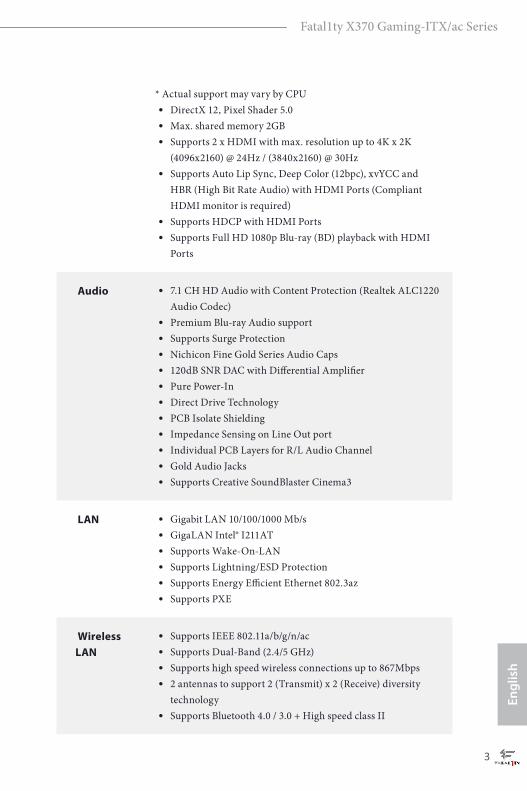
* Actual support may vary by CPU• DirectX 12, Pixel Shader 5.0• Max. shared memory 2GB• Supports 2 x HDMI with max. resolution up to 4K x 2K
(4096x2160) @ 24Hz / (3840x2160) @ 30Hz• Supports Auto Lip Sync, Deep Color (12bpc), xvYCC and
HBR (High Bit Rate Audio) with HDMI Ports (Compliant HDMI monitor is required)
• Supports HDCP with HDMI Ports • Supports Full HD 1080p Blu-ray (BD) playback with HDMI
Ports
Audio • 7.1 CH HD Audio with Content Protection (Realtek ALC1220 Audio Codec)
• Premium Blu-ray Audio support• Supports Surge Protection• Nichicon Fine Gold Series Audio Caps• 120dB SNR DAC with Differential Amplifier• Pure Power-In• Direct Drive Technology• PCB Isolate Shielding• Impedance Sensing on Line Out port• Individual PCB Layers for R/L Audio Channel• Gold Audio Jacks• Supports Creative SoundBlaster Cinema3
LAN • Gigabit LAN 10/100/1000 Mb/s• GigaLAN Intel® I211AT• Supports Wake-On-LAN • Supports Lightning/ESD Protection • Supports Energy Efficient Ethernet 802.3az• Supports PXE
Wireless LAN
• Supports IEEE 802.11a/b/g/n/ac• Supports Dual-Band (2.4/5 GHz)• Supports high speed wireless connections up to 867Mbps• 2 antennas to support 2 (Transmit) x 2 (Receive) diversity
technology • Supports Bluetooth 4.0 / 3.0 + High speed class II

English
4
Rear Panel I/O
• 2 x Antenna Ports• 1 x PS/2 Mouse/Keyboard Port • 2 x HDMI Ports• 1 x Optical SPDIF Out Port• 2 x USB 2.0 Ports (Supports ESD Protection)
* 1 x Fatal1ty Mouse Port (USB 2.0) is included• 1 x USB 3.0 Type-A Port (Supports ESD Protection)• 1 x USB 3.0 Type-C Port (Supports ESD Protection)• 2 x USB 3.0 Ports (Supports ESD Protection)• 1 x RJ-45 LAN Port with LED (ACT/LINK LED and SPEED
LED)• HD Audio Jacks: Rear Speaker / Central / Bass / Line in /
Front Speaker / Microphone (Gold Audio Jacks)
Storage • 4 x SATA3 6.0 Gb/s Connectors, support RAID (RAID 0, RAID 1 and RAID 10), NCQ, AHCI and Hot Plug
• 1 x Ultra M.2 Socket, supports M Key type 2280 M.2 SATA3 6.0 Gb/s module and M.2 PCI Express module up to Gen3 x4 (32 Gb/s) (with Ryzen Series CPU) or Gen3 x2 (16 Gb/s) (with A-Series APU)*
* Supports NVMe SSD as boot disks* Supports ASRock U.2 Kit
Connector • 1 x LPC Header• 1 x AMD Fan LED Header• 1 x CPU Fan Connector (4-pin)
* The CPU Fan Connector supports the CPU fan of maximum 1A (12W) fan power. • 1 x Chassis Fan Connector (4-pin) • 1 x Chassis Optional/Water Pump Fan Connector (4-pin)
(Smart Fan Speed Control) * The Chassis Optional/Water Pump Fan supports the water cooler fan of maximum 1.5A (18W) fan power. * CHA_FAN1/W_PUMP can auto detect if 3-pin or 4-pin fan is in use.• 1 x 24 pin ATX Power Connector • 1 x 8 pin 12V Power Connector (Hi-Density Power
Connector)• 1 x Front Panel Audio Connector • 1 x AMD LED Fan USB Header

Fatal1ty X370 Gaming-ITX/ac Series
5
Engl
ish
• 1 x USB 2.0 Header (Supports 2 USB 2.0 ports) (Supports ESD Protection)
• 1 x USB 3.0 Header (Supports 2 USB 3.0 ports) (Supports ESD Protection)
BIOS Feature
• AMI UEFI Legal BIOS with GUI support• Supports “Plug and Play”• ACPI 5.1 compliance wake up events• Supports jumperfree• SMBIOS 2.3 support• CPU, DRAM, PCH 1.05V, PROM 2.5V, Voltage Multi-adjust-
ment
Hardware Monitor
• Temperature Sensing: CPU, Chassis, Chassis Optional/Water Pump Fans
• Fan Tachometer: CPU, Chassis, Chassis Optional/Water Pump Fans
• Quiet Fan (Auto adjust chassis fan speed by CPU tempera-ture): CPU, Chassis, Chassis Optional/Water Pump Fans
• Fan Multi-Speed Control: CPU, Chassis, Chassis Optional/Water Pump Fans
• Voltage monitoring: +12V, +5V, +3.3V, CPU Vcore
OS • Microsoft® Windows® 10 64-bit * For the updated Windows® 10 driver, please visit ASRock’s web-site for details: http://www.asrock.com
Certifica-tions
• FCC, CE• ErP/EuP ready (ErP/EuP ready power supply is required)
* For detailed product information, please visit our website: http://www.asrock.com
Please realize that there is a certain risk involved with overclocking, including adjust-ing the setting in the BIOS, applying Untied Overclocking Technology, or using third-party overclocking tools. Overclocking may affect your system’s stability, or even cause damage to the components and devices of your system. It should be done at your own risk and expense. We are not responsible for possible damage caused by overclocking.
English
6
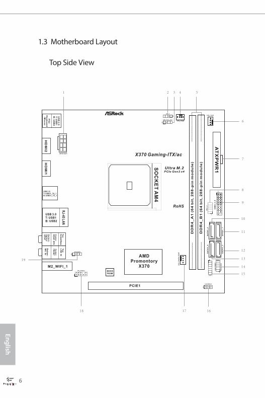
1.3 Motherboard Layout
BIOSROM
AT
XP
WR
1
CLRCMOS1
1
1
US
B_
3_
4
HD_AUDIO1
1
CPU_FAN1
RJ-45
LAN
SO
CK
ET
AM
4
HD
MI2
ATX12V1
Ultra M.2PCIe Gen3 x4
US
B3
_3
_4
1
CHA_FAN2
HD
LE
DR
ES
ET
PL
ED
PW
RB
TN
PANEL1
1
RoHS
DD
R4
_A
1(6
4b
it,
28
8-p
inm
od
ule
)
DD
R4
_B
1(6
4b
it,
28
8-p
inm
od
ule
)
AMDPromontory
X370
USB 3.0T: USB1B: USB2
AMD_FAN_LED1
1
LPC1
1
X370 Gaming-ITX/ac
PCIE1
CH
A_
FA
N/W
_P
UM
P
USB 3.0T: USB31_TA_1B: USB31_TC_1
US
B2
.0T
:U
SB
1B
:U
SB
2
PS
2K
ey
bo
ard
/Mo
us
eH
DM
I1
To
p:
Cen
tral/B
ass
Ce
nte
r:R
EA
RS
PK
To
p:
LIN
EIN
Ce
nte
r:F
RO
NT
Bo
ttom
:O
ptic
al
SP
DIF
Bo
ttom
:M
ICIN
USB_5
1
SPEAKER1
1
M2_WIFI_1
SA
TA
3_
2S
AT
A3
_4
SA
TA
3_
1S
AT
A3
_3
Top Side View

Fatal1ty X370 Gaming-ITX/ac Series
7
Engl
ish
Ult
raM
.2
Back Side View

English
8
No. Description
1 ATX 12V Power Connector (ATX12V1)
2 AMD LED Fan USB Header (USB_5)
3 AMD Fan LED Header (AMD_FAN_LED1)
4 CPU Fan Connector (CPU_FAN1)
5 2 x 288-pin DDR4 DIMM Slots (DDR4_A1, DDR4_B1)
6 Chassis Fan Connector (CHA_FAN2)
7 ATX Power Connector (ATXPWR1)
8 USB 2.0 Header (USB_3_4)
9 USB 3.0 Header (USB3_3_4)
10 SATA3 Connector (SATA3_2)
11 SATA3 Connector (SATA3_1)
12 SATA3 Connector (SATA3_3)
13 SATA3 Connector (SATA3_4)
14 System Panel Header (PANEL1)
15 LPC Header (LPC1)
16 Clear CMOS Jumper (CLRCMOS1)
17 Chassis Fan / Waterpump Fan Connector (CHA_FAN/W_PUMP)
18 Front Panel Audio Header (HD_AUDIO1)
19 Chassis Speaker Header (SPEAKER1)
Fatal1ty X370 Gaming-ITX/ac Series
9
Engl
ish
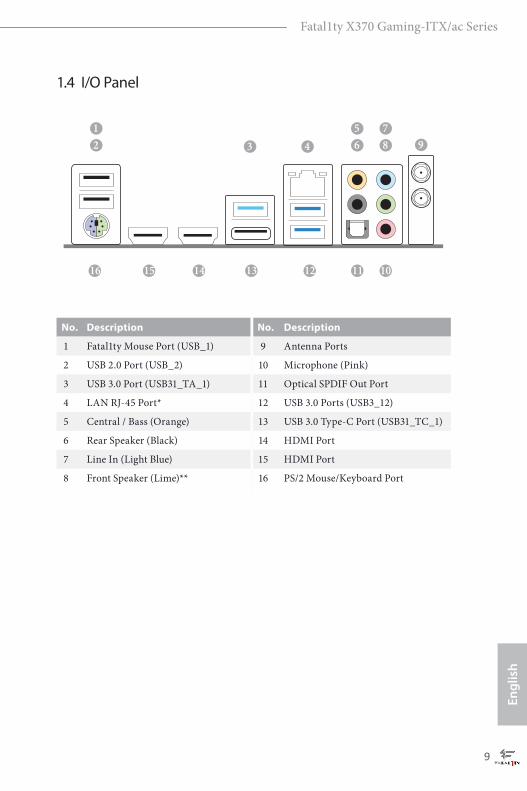
1.4 I/O Panel
No. Description No. Description
1 Fatal1ty Mouse Port (USB_1) 9 Antenna Ports
2 USB 2.0 Port (USB_2) 10 Microphone (Pink)
3 USB 3.0 Port (USB31_TA_1) 11 Optical SPDIF Out Port
4 LAN RJ-45 Port* 12 USB 3.0 Ports (USB3_12)
5 Central / Bass (Orange) 13 USB 3.0 Type-C Port (USB31_TC_1)
6 Rear Speaker (Black) 14 HDMI Port
7 Line In (Light Blue) 15 HDMI Port
8 Front Speaker (Lime)** 16 PS/2 Mouse/Keyboard Port
9
101112131516
65
87
4321
14
English
10
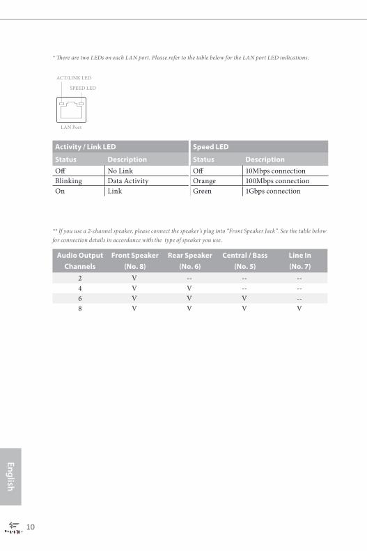
* There are two LEDs on each LAN port. Please refer to the table below for the LAN port LED indications.
Activity / Link LED Speed LED
Status Description Status DescriptionOff No Link Off 10Mbps connectionBlinking Data Activity Orange 100Mbps connectionOn Link Green 1Gbps connection
** If you use a 2-channel speaker, please connect the speaker’s plug into “Front Speaker Jack”. See the table below for connection details in accordance with the type of speaker you use.
Audio Output Channels
Front Speaker(No. 8)
Rear Speaker(No. 6)
Central / Bass(No. 5)
Line In(No. 7)
2 V -- -- --4 V V -- --6 V V V --8 V V V V
ACT/LINK LED
SPEED LED
LAN Port
Fatal1ty X370 Gaming-ITX/ac Series
11
Engl
ish
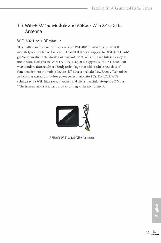
ASRock WiFi 2.4/5 GHz Antenna
1.5 WiFi-802.11ac Module and ASRock WiFi 2.4/5 GHz Antenna
WiFi-802.11ac + BT ModuleThis motherboard comes with an exclusive WiFi 802.11 a/b/g/n/ac + BT v4.0 module (pre-installed on the rear I/O panel) that offers support for WiFi 802.11 a/b/g/n/ac connectivity standards and Bluetooth v4.0. WiFi + BT module is an easy-to-use wireless local area network (WLAN) adapter to support WiFi + BT. Bluetooth v4.0 standard features Smart Ready technology that adds a whole new class of functionality into the mobile devices. BT 4.0 also includes Low Energy Technology and ensures extraordinary low power consumption for PCs. The 2T2R WiFi solution sets a WiFi high speed standard and offers max link rate up to 867Mbps. * The transmission speed may vary according to the environment.

English
12
This is a Mini-ITX form factor motherboard. Before you install the motherboard, study the configuration of your chassis to ensure that the motherboard fits into it.
Pre-installation PrecautionsTake note of the following precautions before you install motherboard components or change any motherboard settings.
• Make sure to unplug the power cord before installing or removing the motherboard. Failure to do so may cause physical injuries to you and damages to motherboard components.
• In order to avoid damage from static electricity to the motherboard’s components, NEVER place your motherboard directly on a carpet. Also remember to use a grounded wrist strap or touch a safety grounded object before you handle the components.
• Hold components by the edges and do not touch the ICs.• Whenever you uninstall any components, place them on a grounded anti-static pad or
in the bag that comes with the components.• When placing screws to secure the motherboard to the chassis, please do not over-
tighten the screws! Doing so may damage the motherboard.
Chapter 2 Installation

Fatal1ty X370 Gaming-ITX/ac Series
13
Engl
ish
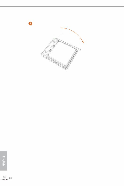
2.1 Installing the CPU
Unplug all power cables before installing the CPU.
2
1
English
14
3
Fatal1ty X370 Gaming-ITX/ac Series
15
Engl
ish
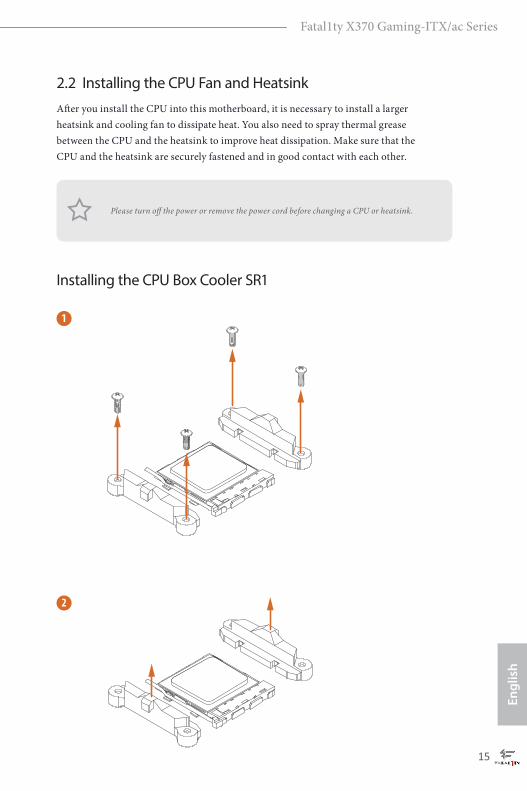
2.2 Installing the CPU Fan and HeatsinkAfter you install the CPU into this motherboard, it is necessary to install a larger heatsink and cooling fan to dissipate heat. You also need to spray thermal grease between the CPU and the heatsink to improve heat dissipation. Make sure that the CPU and the heatsink are securely fastened and in good contact with each other.
Installing the CPU Box Cooler SR1
Please turn off the power or remove the power cord before changing a CPU or heatsink.
1
2
English
16
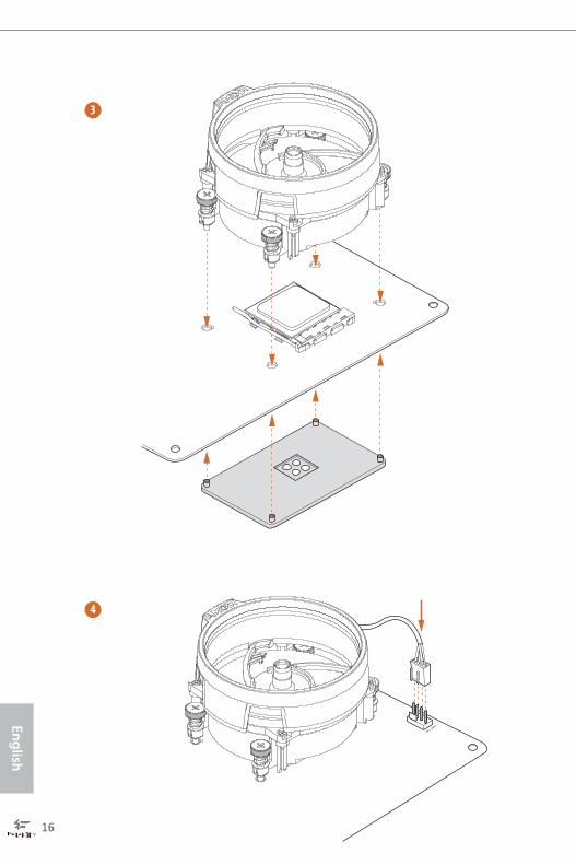
3
4
CPU_FAN1
Fatal1ty X370 Gaming-ITX/ac Series
17
Engl
ish
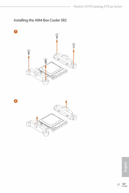
Installing the AM4 Box Cooler SR2
1
2

English
18
3

Fatal1ty X370 Gaming-ITX/ac Series
19
Engl
ish
4-pin FAN cable
RGB LED Cable
+12V
*The diagram shown here are for reference only. Please refer to page 31 for the orientation of AMD Fan LED Header (AMD_FAN_LED1).
5
CPU_FAN1
AMD_FAN_LED1
4
CPU_FAN1

English
20
Installing the AM4 Box Cooler SR3
1
2

Fatal1ty X370 Gaming-ITX/ac Series
21
Engl
ish
3
4
English
22
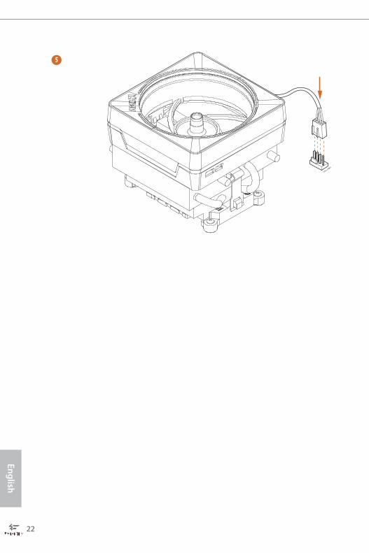
5
CPU_FAN1
Fatal1ty X370 Gaming-ITX/ac Series
23
Engl
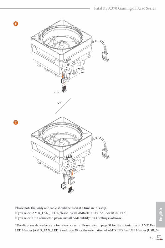
ishPlease note that only one cable should be used at a time in this step.
If you select AMD_FAN_LED1, please install ASRock utility "ASRock RGB LED". If you select USB connector, please install AMD utility "SR3 Settings Software".
*The diagram shown here are for reference only. Please refer to page 31 for the orientation of AMD Fan LED Header (AMD_FAN_LED1) and page 29 for the orientation of AMD LED Fan USB Header (USB_5).
7
6
CPU_FAN1
AMD_FAN_LED1
CPU_FAN1
AMD_FAN_LED1
USB_5
or
+12V
English
24
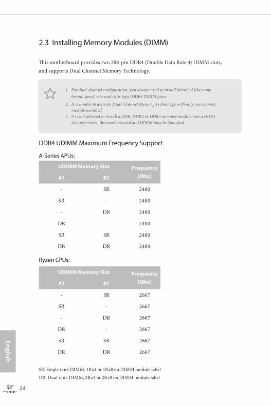
2.3 Installing Memory Modules (DIMM)
This motherboard provides two 288-pin DDR4 (Double Data Rate 4) DIMM slots, and supports Dual Channel Memory Technology.
DDR4 UDIMM Maximum Frequency Support
A-Series APUs:
Ryzen CPUs:
SR: Single rank DIMM, 1Rx4 or 1Rx8 on DIMM module label
DR: Dual rank DIMM, 2Rx4 or 2Rx8 on DIMM module label
1. For dual channel configuration, you always need to install identical (the same brand, speed, size and chip-type) DDR4 DIMM pairs.
2. It is unable to activate Dual Channel Memory Technology with only one memory module installed.
3. It is not allowed to install a DDR, DDR2 or DDR3 memory module into a DDR4 slot; otherwise, this motherboard and DIMM may be damaged.
UDIMM Memory Slot Frequency (Mhz)A1 B1
- SR 2400
SR - 2400
- DR 2400
DR - 2400
SR SR 2400
DR DR 2400
UDIMM Memory Slot Frequency (Mhz)A1 B1
- SR 2667
SR - 2667
- DR 2667
DR - 2667
SR SR 2667
DR DR 2667
Fatal1ty X370 Gaming-ITX/ac Series
25
Engl
ish
1
2
3
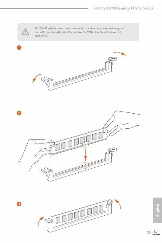
The DIMM only fits in one correct orientation. It will cause permanent damage to the motherboard and the DIMM if you force the DIMM into the slot at incorrect orientation.
English
26
2.4 Expansion Slot (PCI Express Slot)There is 1 PCI Express slot on the motherboard.
PCIe slot:
PCIE1 (PCIe 3.0 x16 slot) is used for PCI Express x16 lane width graphics cards.* * PCIE1 will downgrade to x8 mode when A-Series APU is installed.
Before installing an expansion card, please make sure that the power supply is switched off or the power cord is unplugged. Please read the documentation of the expansion card and make necessary hardware settings for the card before you start the installation.
Fatal1ty X370 Gaming-ITX/ac Series
27
Engl
ish
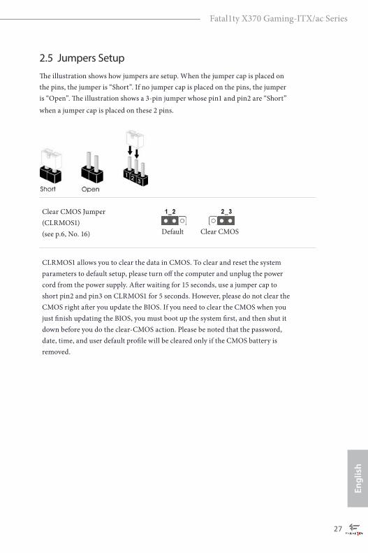
2.5 Jumpers SetupThe illustration shows how jumpers are setup. When the jumper cap is placed on the pins, the jumper is “Short”. If no jumper cap is placed on the pins, the jumper is “Open”. The illustration shows a 3-pin jumper whose pin1 and pin2 are “Short” when a jumper cap is placed on these 2 pins.
Clear CMOS Jumper(CLRMOS1)(see p.6, No. 16)
CLRMOS1 allows you to clear the data in CMOS. To clear and reset the system parameters to default setup, please turn off the computer and unplug the power cord from the power supply. After waiting for 15 seconds, use a jumper cap to short pin2 and pin3 on CLRMOS1 for 5 seconds. However, please do not clear the CMOS right after you update the BIOS. If you need to clear the CMOS when you just finish updating the BIOS, you must boot up the system first, and then shut it down before you do the clear-CMOS action. Please be noted that the password, date, time, and user default profile will be cleared only if the CMOS battery is removed.
Clear CMOSDefault
English
28
2.6 Onboard Headers and Connectors
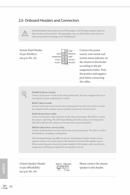
System Panel Header(9-pin PANEL1)(see p.6, No. 14)
Connect the power switch, reset switch and system status indicator on the chassis to this header according to the pin assignments below. Note the positive and negative pins before connecting the cables.
Chassis Speaker Header(4-pin SPEAKER1)(see p.6, No. 19)
Please connect the chassis speaker to this header.
PWRBTN (Power Switch): Connect to the power switch on the chassis front panel. You may configure the way to turn off your system using the power switch.
RESET (Reset Switch):Connect to the reset switch on the chassis front panel. Press the reset switch to restart the computer if the computer freezes and fails to perform a normal restart.
PLED (System Power LED):Connect to the power status indicator on the chassis front panel. The LED is on when the system is operating. The LED keeps blinking when the system is in S3 sleep state. The LED is off when the system is in S4 sleep state or powered off (S5).
HDLED (Hard Drive Activity LED):Connect to the hard drive activity LED on the chassis front panel. The LED is on when the hard drive is reading or writing data.
The front panel design may differ by chassis. A front panel module mainly consists of power switch, reset switch, power LED, hard drive activity LED, speaker and etc. When connecting your chassis front panel module to this header, make sure the wire assignments and the pin assignments are matched correctly.
Onboard headers and connectors are NOT jumpers. Do NOT place jumper caps over these headers and connectors. Placing jumper caps over the headers and connectors will cause permanent damage to the motherboard.
GND RESET#
PWRBTN#
PLED-
PLED+
GND
HDLED-
HDLED+
1
GND
Fatal1ty X370 Gaming-ITX/ac Series
29
Engl
ish
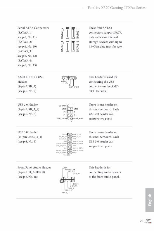
Serial ATA3 Connectors(SATA3_1: see p.6, No. 11)(SATA3_2: see p.6, No. 10)(SATA3_3: see p.6, No. 12)(SATA3_4: see p.6, No. 13)
These four SATA3 connectors support SATA data cables for internal storage devices with up to 6.0 Gb/s data transfer rate.
AMD LED Fan USB Header (4-pin USB_5)(see p.6, No. 2)
This header is used for connecting the USB connector on the AMD SR3 Heatsink.
USB 2.0 Header(9-pin USB_3_4)(see p.6, No. 8)
There is one header on this motherboard. Each USB 2.0 header can support two ports.
USB 3.0 Header(19-pin USB3_3_4)(see p.6, No. 9)
There is one header on this motherboard. Each USB 3.0 header can support two ports.
Front Panel Audio Header(9-pin HD_AUDIO1)(see p.6, No. 18)
This header is for connecting audio devices to the front audio panel.
SAT
A3_
2
SAT
A3_
1
SAT
A3_
4
SAT
A3_
3
1
IntA_PB_D+
Dummy
IntA_PB_D-
GND
IntA_PB_SSTX+
GND
IntA_PB_SSTX-
IntA_PB_SSRX+
IntA_PB_SSRX-
Vbus
Vbus
IntA_PA_SSRX-
IntA_PA_SSRX+
GND
IntA_PA_SSTX-
IntA_PA_SSTX+
GND
IntA_PA_D-
IntA_PA_D+
J_SENSE
OUT2_L
1
MIC_RETPRESENCE#
GND
OUT2_RMIC2_R
MIC2_L
OUT_RET

English
30
Chassis Fan Connector(4-pin CHA_FAN2)(see p.6, No. 6)
Please connect fan cables to the fan connectors and match the black wire to the ground pin.
Chassis Optional/Water Pump Fan Connector (4-pin CHA_FAN/W_PUMP)(see p.6, No. 17)
This motherboard provides two 4-Pin water cooling chassis fan connectors. If you plan to connect a 3-Pin chassis water cooler fan, please connect it to Pin 1-3.
CPU Fan Connector(4-pin CPU_FAN1)(see p.6, No. 4)
This motherboard pro-vides a 4-Pin CPU fan (Quiet Fan) connector. If you plan to connect a 3-Pin CPU fan, please connect it to Pin 1-3.
GND
FAN_VOLTAGE_CONTROL
FAN_SPEED
FAN_SPEED_CONTROL
1. High Definition Audio supports Jack Sensing, but the panel wire on the chassis must support HDA to function correctly. Please follow the instructions in our manual and chassis manual to install your system.
2. If you use an AC’97 audio panel, please install it to the front panel audio header by the steps below: A. Connect Mic_IN (MIC) to MIC2_L. B. Connect Audio_R (RIN) to OUT2_R and Audio_L (LIN) to OUT2_L. C. Connect Ground (GND) to Ground (GND). D. MIC_RET and OUT_RET are for the HD audio panel only. You don’t need to connect them for the AC’97 audio panel. E. To activate the front mic, go to the “FrontMic” Tab in the Realtek Control panel and adjust “Recording Volume”.
GNDFAN_VOLTAGE
CHA_FAN_SPEEDFAN_SPEED_CONTROL
CPU_FFAN_VOLTAGE
GND
AN_SPEEDFAN_SPEED_CONTROL
4 3 2 1

Fatal1ty X370 Gaming-ITX/ac Series
31
Engl
ish
ATX Power Connector(24-pin ATXPWR1)(see p.6, No. 7)
This motherboard pro-vides a 24-pin ATX power connector. To use a 20-pin ATX power supply, please plug it along Pin 1 and Pin 13.
ATX 12V Power Connector(8-pin ATX12V1)(see p.6, No. 1)
This motherboard provides a 8-pin ATX 12V power connector. To use a 4-pin ATX power supply, please plug it along Pin 1 and Pin 5.
AMD FAN LED Header(4-pin AMD_FAN_LED1)(see p.6, No. 3)
AMD FAN LED Header is used to connect RGB LED extension cable that comes with AMD heatsink. The cable connection allows users to choose from various LED lighting effects.Caution: Never install the FAN LED cable in the wrong orienta-tion; otherwise, the cable may be damaged.
12
1
24
13
12V G R B1
5
8
1
4

English
32
Chapter 3 Software and Utilities Operation 3.1 Installing DriversThe Support CD that comes with the motherboard contains necessary drivers and useful utilities that enhance the motherboard’s features.
Running The Support CDTo begin using the support CD, insert the CD into your CD-ROM drive. The CD automatically displays the Main Menu if “AUTORUN” is enabled in your computer. If the Main Menu does not appear automatically, locate and double click on the file “ASRSETUP.EXE” in the Support CD to display the menu.
Drivers MenuThe drivers compatible to your system will be auto-detected and listed on the support CD driver page. Please click Install All or follow the order from top to bottom to install those required drivers. Therefore, the drivers you install can work properly.
Utilities MenuThe Utilities Menu shows the application software that the motherboard supports. Click on a specific item then follow the installation wizard to install it.
To improve Windows 7 compatibility, please download and install the following hot fix provided by Microsoft. “KB2720599”: http://support.microsoft.com/kb/2720599/en-us

Fatal1ty X370 Gaming-ITX/ac Series
33
Engl
ish
3.2 F-StreamF-Stream is ASRock’s multi purpose software suite with a new interface, more new features and improved utilities.
3.2.1 Installing F-Stream
F-Stream can be downloaded from ASRock Live Update & APP Shop. After the installation, you will find the icon “F-Stream“ on your desktop. Double-click the “F-Stream“ icon, F-Stream main menu will pop up.
3.2.2 Using F-Stream
There are five sections in F-Stream main menu: Operation Mode, OC Tweaker, System Info, FAN-Tastic Tuning and Settings.
Operation ModeChoose an operation mode for your computer.

English
34
OC TweakerConfigurations for overclocking the system.
System InfoView information about the system. *The System Browser tab may not appear for certain models.

Fatal1ty X370 Gaming-ITX/ac Series
35
Engl
ish
FAN-Tastic Tuning
Configure up to five different fan speeds using the graph. The fans will automatically shift to the next speed level when the assigned temperature is met.
SettingsConfigure ASRock F-Stream. Click to select "Auto run at Windows Startup" if you want F-Stream to be launched when you start up the Windows operating system.
English
36
3.3 ASRock Live Update & APP ShopThe ASRock Live Update & APP Shop is an online store for purchasing and downloading software applications for your ASRock computer. You can quickly and easily install various apps and support utilities. With ASRock Live Update & APP Shop, you can optimize your system and keep your motherboard up to date simply with a few clicks.
Double-click on your desktop to access ASRock Live Update & APP Shop utility.
*You need to be connected to the Internet to download apps from the ASRock Live Update & APP Shop.
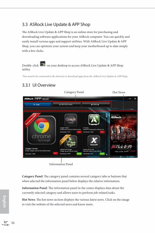
3.3.1 UI Overview
Category Panel: The category panel contains several category tabs or buttons that when selected the information panel below displays the relative information.
Information Panel: The information panel in the center displays data about the currently selected category and allows users to perform job-related tasks.
Hot News: The hot news section displays the various latest news. Click on the image to visit the website of the selected news and know more.
Information Panel
Hot NewsCategory Panel

Fatal1ty X370 Gaming-ITX/ac Series
37
Engl
ish
3.3.2 Apps
When the "Apps" tab is selected, you will see all the available apps on screen for you to download.
Installing an AppStep 1
Find the app you want to install.
The most recommended app appears on the left side of the screen. The other various apps are shown on the right. Please scroll up and down to see more apps listed.
You can check the price of the app and whether you have already intalled it or not.
- The red icon displays the price or "Free" if the app is free of charge.
- The green "Installed" icon means the app is installed on your computer.
Step 2
Click on the app icon to see more details about the selected app.

English
38
Step 3
If you want to install the app, click on the red icon to start downloading.
Step 4
When installation completes, you can find the green "Installed" icon appears on the upper right corner.
To uninstall it, simply click on the trash can icon . *The trash icon may not appear for certain apps.

Fatal1ty X370 Gaming-ITX/ac Series
39
Engl
ish
Upgrading an AppYou can only upgrade the apps you have already installed. When there is an available new version for your app, you will find the mark of "New Version" appears below the installed app icon.
Step 1
Click on the app icon to see more details.
Step 2
Click on the yellow icon to start upgrading.

English
40
3.3.3 BIOS & Drivers
Installing BIOS or Drivers
When the "BIOS & Drivers" tab is selected, you will see a list of recommended or critical updates for the BIOS or drivers. Please update them all soon.
Step 1
Please check the item information before update. Click on to see more details.
Step 2
Click to select one or more items you want to update.
Step 3
Click Update to start the update process.
Fatal1ty X370 Gaming-ITX/ac Series
41
Engl
ish
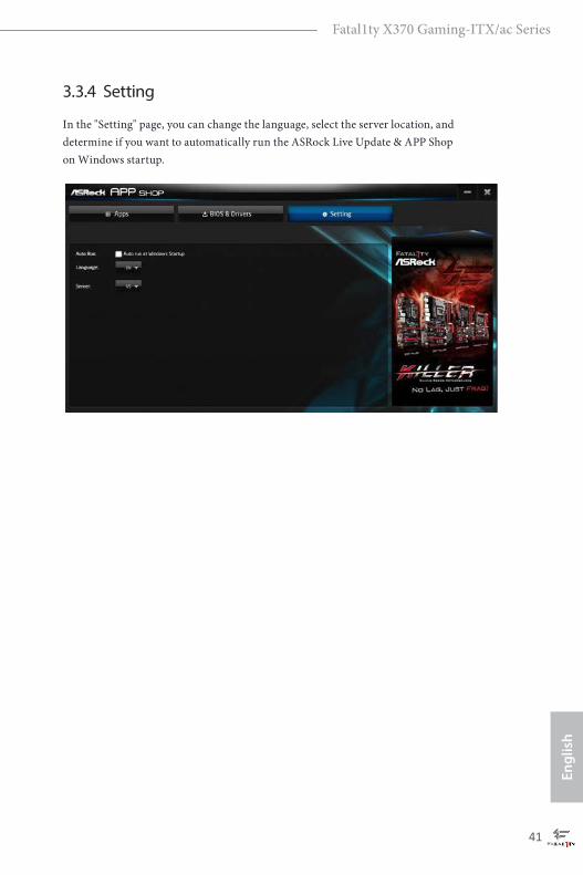
3.3.4 Setting
In the "Setting" page, you can change the language, select the server location, and determine if you want to automatically run the ASRock Live Update & APP Shop on Windows startup.
English
42
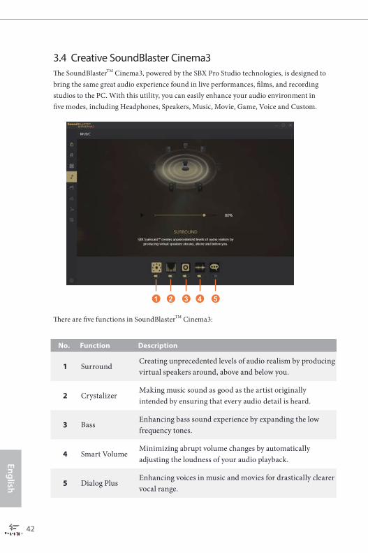
3.4 Creative SoundBlaster Cinema3The SoundBlasterTM Cinema3, powered by the SBX Pro Studio technologies, is designed to bring the same great audio experience found in live performances, films, and recording studios to the PC. With this utility, you can easily enhance your audio environment in five modes, including Headphones, Speakers, Music, Movie, Game, Voice and Custom.
1 2 3 4 5
There are five functions in SoundBlasterTM Cinema3:
No. Function Description
1 Surround Creating unprecedented levels of audio realism by producing virtual speakers around, above and below you.
2 CrystalizerMaking music sound as good as the artist originally intended by ensuring that every audio detail is heard.
3 BassEnhancing bass sound experience by expanding the low frequency tones.
4 Smart Volume Minimizing abrupt volume changes by automatically adjusting the loudness of your audio playback.
5 Dialog Plus Enhancing voices in music and movies for drastically clearer vocal range.

Fatal1ty X370 Gaming-ITX/ac Series
43
Engl
ish
3.5 ASRock RGB LED UtilityNow you can adjust the RGB LED color through the ASRock RGB LED utility. Download this utility from the ASRock Live Update & APP Shop and start coloring your PC style your way!
Toggle on/off the RGB LED switch
Sync RGB LED effects for all LED regions of the motherboard
Select a RGB LED light effect from the drop-down menu.
Drag the tab to customize your preference.
English
44
Chapter 4 UEFI SETUP UTILITY
4.1 IntroductionThis section explains how to use the UEFI SETUP UTILITY to configure your system. You may run the UEFI SETUP UTILITY by pressing <F2> or <Del> right after you power on the computer, otherwise, the Power-On-Self-Test (POST) will continue with its test routines. If you wish to enter the UEFI SETUP UTILITY after POST, restart the system by pressing <Ctl> + <Alt> + <Delete>, or by pressing the reset button on the system chassis. You may also restart by turning the system off and then back on.
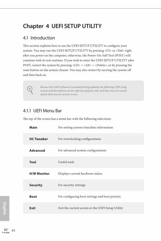
4.1.1 UEFI Menu Bar
The top of the screen has a menu bar with the following selections:
Main For setting system time/date information
OC Tweaker For overclocking configurations
Advanced For advanced system configurations
Tool Useful tools
H/W Monitor Displays current hardware status
Security For security settings
Boot For configuring boot settings and boot priority
Exit Exit the current screen or the UEFI Setup Utility
Because the UEFI software is constantly being updated, the following UEFI setup screens and descriptions are for reference purpose only, and they may not exactly match what you see on your screen.

Fatal1ty X370 Gaming-ITX/ac Series
45
Engl
ish
4.1.2 Navigation KeysUse < > key or < > key to choose among the selections on the menu bar, and use < > key or < > key to move the cursor up or down to select items, then press <Enter> to get into the sub screen. You can also use the mouse to click your required item.
Please check the following table for the descriptions of each navigation key.
Navigation Key(s) Description
+ / - To change option for the selected items
<Tab> Switch to next function
<PGUP> Go to the previous page
<PGDN> Go to the next page
<HOME> Go to the top of the screen
<END> Go to the bottom of the screen
<F1> To display the General Help Screen
<F7> Discard changes and exit the SETUP UTILITY
<F9> Load optimal default values for all the settings
<F10> Save changes and exit the SETUP UTILITY
<F12> Print screen
<ESC> Jump to the Exit Screen or exit the current screen
English
46
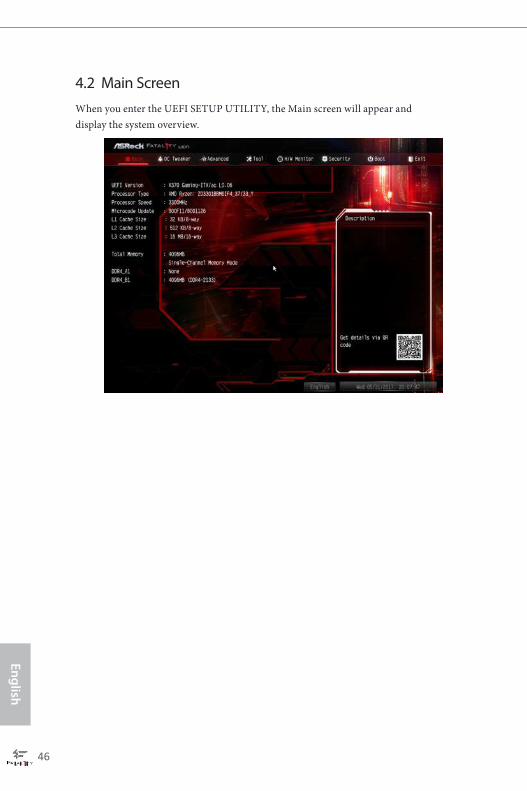
4.2 Main ScreenWhen you enter the UEFI SETUP UTILITY, the Main screen will appear and display the system overview.

Fatal1ty X370 Gaming-ITX/ac Series
47
Engl
ish
4.3 OC Tweaker Screen
In the OC Tweaker screen, you can set up overclocking features.
Voltage Configuration
DRAM VoltageUse this to select DRAM Voltage. The default value is [Auto].
2.50V VoltageConfigure the voltage for the 2.50V PROM.
+1.8 VoltageConfigure +1.8V voltage.
1.05V VoltageChipset 1.05V Voltage. Use default settings for best performance.
Save User Default
Because the UEFI software is constantly being updated, the following UEFI setup screens and descriptions are for reference purpose only, and they may not exactly match what you see on your screen.

English
48
Type a profile name and press enter to save your settings as user default.
Load User DefaultLoad previously saved user defaults.
Save User UEFI Setup Profile to DiskIt helps you to save current UEFI settings as an user profile to disk.
Load User UEFI Setup Profile from DiskYou can load previous saved profile from the disk.
Fatal1ty X370 Gaming-ITX/ac Series
49
Engl
ish
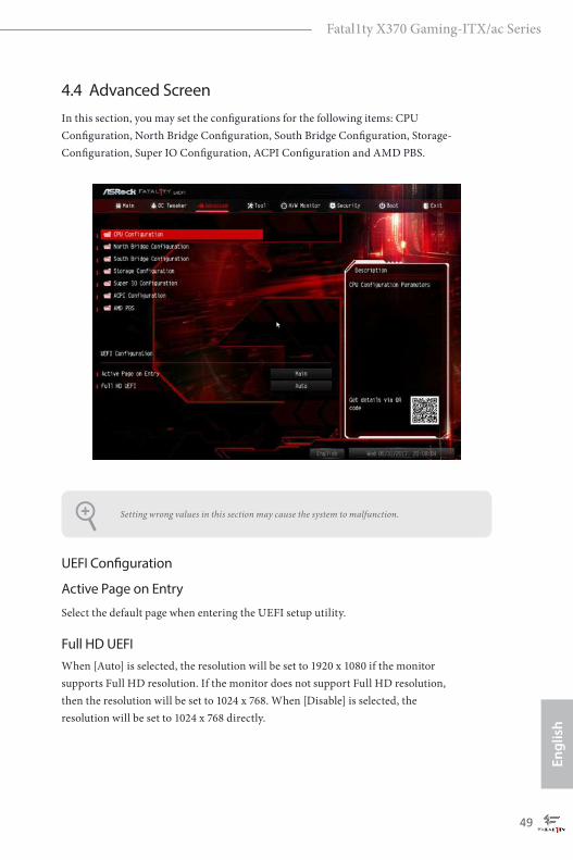
4.4 Advanced ScreenIn this section, you may set the configurations for the following items: CPU Configuration, North Bridge Configuration, South Bridge Configuration, Storage-Configuration, Super IO Configuration, ACPI Configuration and AMD PBS.
UEFI Configuration
Active Page on Entry
Select the default page when entering the UEFI setup utility.
Full HD UEFIWhen [Auto] is selected, the resolution will be set to 1920 x 1080 if the monitor supports Full HD resolution. If the monitor does not support Full HD resolution, then the resolution will be set to 1024 x 768. When [Disable] is selected, the resolution will be set to 1024 x 768 directly.
Setting wrong values in this section may cause the system to malfunction.
English
50
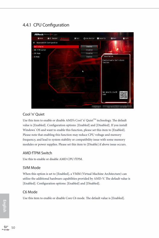
4.4.1 CPU Configuration
Cool 'n' QuietUse this item to enable or disable AMD’s Cool ‘n’ QuietTM technology. The default value is [Enabled]. Configuration options: [Enabled] and [Disabled]. If you install Windows® OS and want to enable this function, please set this item to [Enabled]. Please note that enabling this function may reduce CPU voltage and memory frequency, and lead to system stability or compatibility issue with some memory modules or power supplies. Please set this item to [Disable] if above issue occurs.
AMD fTPM SwitchUse this to enable or disable AMD CPU fTPM.
SVM ModeWhen this option is set to [Enabled], a VMM (Virtual Machine Architecture) can utilize the additional hardware capabilities provided by AMD-V. The default value is [Enabled]. Configuration options: [Enabled] and [Disabled].
C6 ModeUse this item to enable or disable Core C6 mode. The default value is [Enabled].
Fatal1ty X370 Gaming-ITX/ac Series
51
Engl
ish
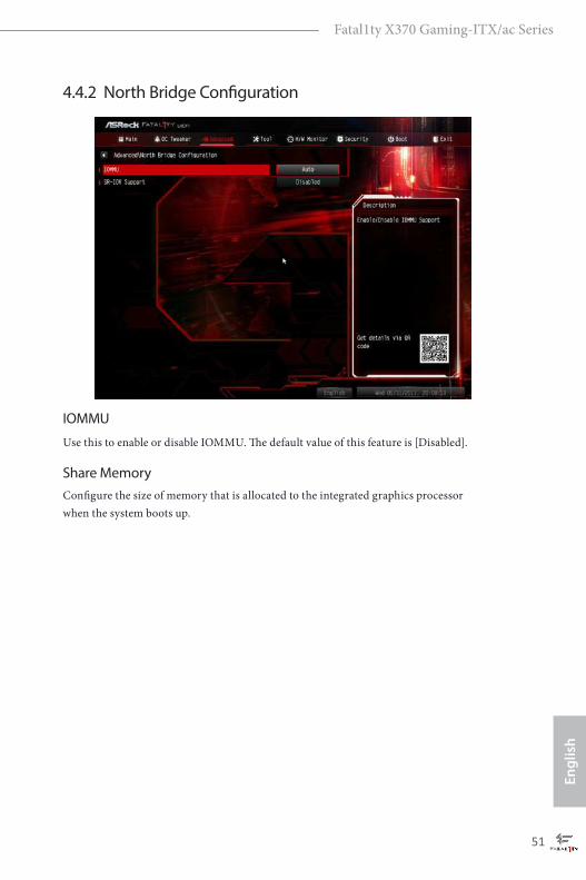
4.4.2 North Bridge Configuration
IOMMU
Use this to enable or disable IOMMU. The default value of this feature is [Disabled].
Share MemoryConfigure the size of memory that is allocated to the integrated graphics processor when the system boots up.
English
52
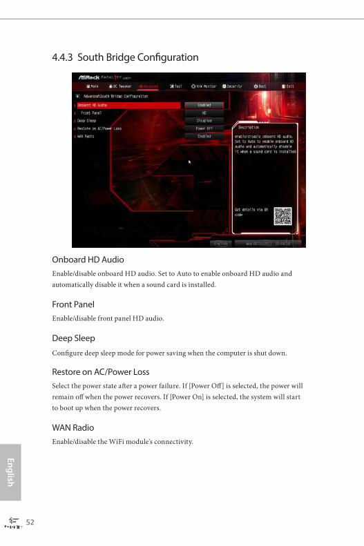
4.4.3 South Bridge Configuration
Onboard HD AudioEnable/disable onboard HD audio. Set to Auto to enable onboard HD audio and automatically disable it when a sound card is installed.
Front PanelEnable/disable front panel HD audio.
Deep Sleep
Configure deep sleep mode for power saving when the computer is shut down.
Restore on AC/Power LossSelect the power state after a power failure. If [Power Off] is selected, the power will remain off when the power recovers. If [Power On] is selected, the system will start to boot up when the power recovers.
WAN RadioEnable/disable the WiFi module's connectivity.

Fatal1ty X370 Gaming-ITX/ac Series
53
Engl
ish
4.4.4 Storage Configuration
SATA Controller(s)Enable/disable the SATA controllers.
SATA ModeAHCI: Supports new features that improve performance.
RAID: Combine multiple disk drives into a logical unit.
SATA Hot Plug Enable/disable the SATA Hot Plug.
English
54
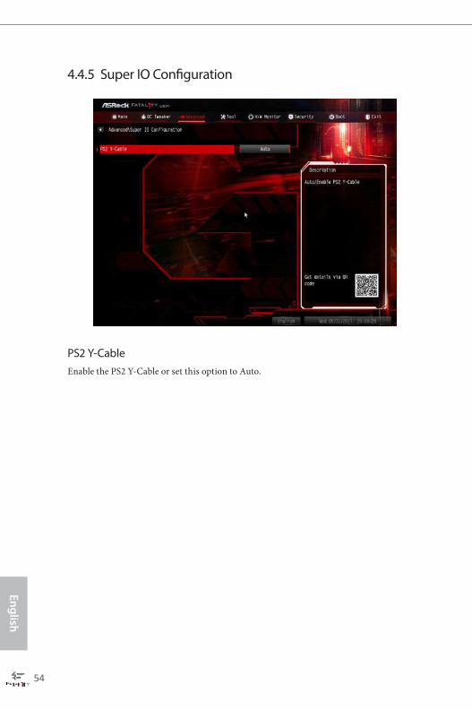
4.4.5 Super IO Configuration
PS2 Y-CableEnable the PS2 Y-Cable or set this option to Auto.
Fatal1ty X370 Gaming-ITX/ac Series
55
Engl
ish
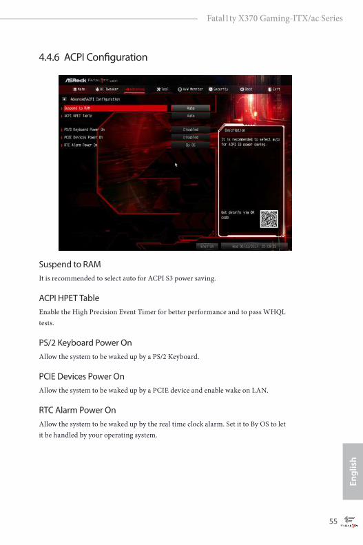
4.4.6 ACPI Configuration
Suspend to RAMIt is recommended to select auto for ACPI S3 power saving.
ACPI HPET TableEnable the High Precision Event Timer for better performance and to pass WHQL tests.
PS/2 Keyboard Power OnAllow the system to be waked up by a PS/2 Keyboard.
PCIE Devices Power OnAllow the system to be waked up by a PCIE device and enable wake on LAN.
RTC Alarm Power OnAllow the system to be waked up by the real time clock alarm. Set it to By OS to let it be handled by your operating system.

English
56
4.4.7 AMD PBS
PCIe x16/2x8 Switch (only for Ryzen Series CPUs (Summit Ridge))Switch PCIe x16 slot to 1x16 or 2x8.

Fatal1ty X370 Gaming-ITX/ac Series
57
Engl
ish
4.5 Tools
RGB LEDASRock RGB LED allows you to adjust the RGB LED color to your liking.
Easy RAID InstallerEasy RAID Installer helps you to copy the RAID driver from the support CD to your USB storage device. After copying the drivers please change the SATA mode to RAID, then you can start installing the operating system in RAID mode.
English
58
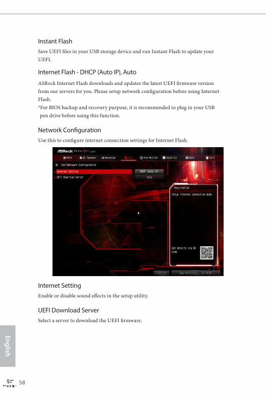
Instant FlashSave UEFI files in your USB storage device and run Instant Flash to update your UEFI.
Internet Flash - DHCP (Auto IP), Auto
ASRock Internet Flash downloads and updates the latest UEFI firmware version from our servers for you. Please setup network configuration before using Internet Flash. *For BIOS backup and recovery purpose, it is recommended to plug in your USB pen drive before using this function.
Network ConfigurationUse this to configure internet connection settings for Internet Flash.
Internet SettingEnable or disable sound effects in the setup utility.
UEFI Download ServerSelect a server to download the UEFI firmware.
Fatal1ty X370 Gaming-ITX/ac Series
59
Engl
ish
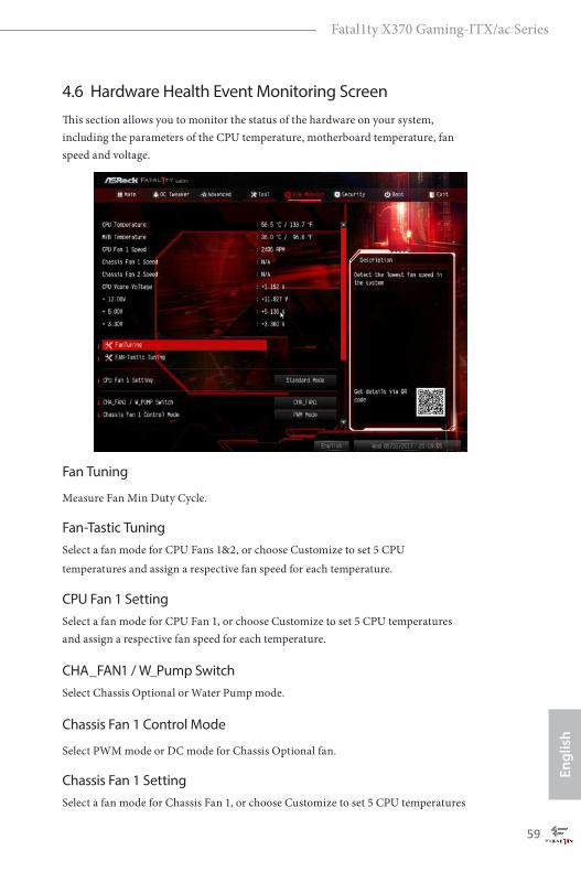
4.6 Hardware Health Event Monitoring ScreenThis section allows you to monitor the status of the hardware on your system, including the parameters of the CPU temperature, motherboard temperature, fan speed and voltage.
Fan Tuning
Measure Fan Min Duty Cycle.
Fan-Tastic TuningSelect a fan mode for CPU Fans 1&2, or choose Customize to set 5 CPU temperatures and assign a respective fan speed for each temperature.
CPU Fan 1 SettingSelect a fan mode for CPU Fan 1, or choose Customize to set 5 CPU temperatures and assign a respective fan speed for each temperature.
CHA_FAN1 / W_Pump SwitchSelect Chassis Optional or Water Pump mode.
Chassis Fan 1 Control Mode
Select PWM mode or DC mode for Chassis Optional fan.
Chassis Fan 1 SettingSelect a fan mode for Chassis Fan 1, or choose Customize to set 5 CPU temperatures

English
60
and assign a respective fan speed for each temperature.
Chassis Fan 1 Temp Source
Select a fan temperature source for Chassis Fan 1.
Chassis Fan 2 SettingSelect a fan mode for Chassis Fan 2, or choose Customize to set 5 CPU temperatures and assign a respective fan speed for each temperature.
Chassis Fan 2 Temp Source
Select a fan temperature source for Chassis Fan 2.
Over Temperature ProtectionWhen Over Temperature Protection is enabled, the system automatically shuts down when the motherboard is overheated.
Fatal1ty X370 Gaming-ITX/ac Series
61
Engl
ish
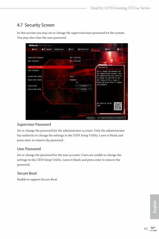
4.7 Security ScreenIn this section you may set or change the supervisor/user password for the system. You may also clear the user password.
Supervisor PasswordSet or change the password for the administrator account. Only the administrator has authority to change the settings in the UEFI Setup Utility. Leave it blank and press enter to remove the password.
User PasswordSet or change the password for the user account. Users are unable to change the settings in the UEFI Setup Utility. Leave it blank and press enter to remove the password.
Secure BootEnable to support Secure Boot.
English
62
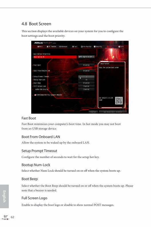
4.8 Boot ScreenThis section displays the available devices on your system for you to configure the boot settings and the boot priority.
Fast BootFast Boot minimizes your computer's boot time. In fast mode you may not boot from an USB storage device.
Boot From Onboard LANAllow the system to be waked up by the onboard LAN.
Setup Prompt Timeout
Configure the number of seconds to wait for the setup hot key.
Bootup Num-LockSelect whether Num Lock should be turned on or off when the system boots up.
Boot Beep
Select whether the Boot Beep should be turned on or off when the system boots up. Please note that a buzzer is needed.
Full Screen Logo
Enable to display the boot logo or disable to show normal POST messages.

Fatal1ty X370 Gaming-ITX/ac Series
63
Engl
ish
AddOn ROM DisplayEnable AddOn ROM Display to see the AddOn ROM messages or configure the AddOn ROM if you've enabled Full Screen Logo. Disable for faster boot speed.

English
64
CSM (Compatibility Support Module)
CSM Enable to launch the Compatibility Support Module. Please do not disable unless you’re running a WHCK test.
Launch PXE OpROM Policy Select UEFI only to run those that support UEFI option ROM only. Select Legacy only to run those that support legacy option ROM only. Select Do not launch to not execute both legacy and UEFI option ROM.
Launch Storage OpROM PolicySelect UEFI only to run those that support UEFI option ROM only. Select Legacy only to run those that support legacy option ROM only. Select Do not launch to not execute both legacy and UEFI option ROM.
Launch Video OpROM Policy Select UEFI only to run those that support UEFI option ROM only. Select Legacy only to run those that support legacy option ROM only. Select Do not launch to not execute both legacy and UEFI option ROM.

Fatal1ty X370 Gaming-ITX/ac Series
65
Engl
ish
4.9 Exit Screen
Save Changes and ExitWhen you select this option the following message, “Save configuration changes and exit setup?” will pop out. Select [OK] to save changes and exit the UEFI SETUP UTILITY.
Discard Changes and ExitWhen you select this option the following message, “Discard changes and exit setup?” will pop out. Select [OK] to exit the UEFI SETUP UTILITY without saving any changes.
Discard ChangesWhen you select this option the following message, “Discard changes?” will pop out. Select [OK] to discard all changes.
Load UEFI DefaultsLoad UEFI default values for all options. The F9 key can be used for this operation.
Launch EFI Shell from filesystem deviceCopy shellx64.efi to the root directory to launch EFI Shell.

English
66
Contact Information
If you need to contact ASRock or want to know more about ASRock, you’re welcome to visit ASRock’s website at http://www.asrock.com; or you may contact your dealer for further information. For technical questions, please submit a support request form at http://www.asrock.com/support/tsd.asp
ASRock Incorporation2F., No.37, Sec. 2, Jhongyang S. Rd., Beitou District,
Taipei City 112, Taiwan (R.O.C.)
ASRock EUROPE B.V.Bijsterhuizen 11-11
6546 AR Nijmegen
The Netherlands
Phone: +31-24-345-44-33
Fax: +31-24-345-44-38
ASRock America, Inc.13848 Magnolia Ave, Chino, CA91710
U.S.A.
Phone: +1-909-590-8308
Fax: +1-909-590-1026