user manual - bitgravityasrock.pc.cdn.bitgravity.com/manual/fatal1ty z97... · 2015-11-23 · user...
TRANSCRIPT

User Manual

Version 1.0 Published May 2014 Copyright©2014 ASRock INC. All rights reserved.
Copyright Notice:No part of this documentation may be reproduced, transcribed, transmitted, or translated in any language, in any form or by any means, except duplication of documentation by the purchaser for backup purpose, without written consent of ASRock Inc.
Products and corporate names appearing in this documentation may or may not be registered trademarks or copyrights of their respective companies, and are used only for identification or explanation and to the owners’ benefit, without intent to infringe.
Disclaimer:Specifications and information contained in this documentation are furnished for informational use only and subject to change without notice, and should not be constructed as a commitment by ASRock. ASRock assumes no responsibility for any errors or omissions that may appear in this documentation.
With respect to the contents of this documentation, ASRock does not provide warranty of any kind, either expressed or implied, including but not limited to the implied warranties or conditions of merchantability or fitness for a particular purpose.
In no event shall ASRock, its directors, officers, employees, or agents be liable for any indirect, special, incidental, or consequential damages (including damages for loss of profits, loss of business, loss of data, interruption of business and the like), even if ASRock has been advised of the possibility of such damages arising from any defect or error in the documentation or product.
This device complies with Part 15 of the FCC Rules. Operation is subject to the following two conditions: (1) this device may not cause harmful interference, and (2) this device must accept any interference received, including interference that
may cause undesired operation.
CALIFORNIA, USA ONLYThe Lithium battery adopted on this motherboard contains Perchlorate, a toxic substance controlled in Perchlorate Best Management Practices (BMP) regulations passed by the California Legislature. When you discard the Lithium battery in California, USA, please follow the related regulations in advance.“Perchlorate Material-special handling may apply, see www.dtsc.ca.gov/hazardouswaste/perchlorate”
ASRock Website: http://www.asrock.com

The terms HDMI™ and HDMI High-Definition Multimedia Interface, and the HDMI logo are trademarks or registered trademarks of HDMI Licensing LLC in the United States and other countries.
Manufactured under license under U.S. Patent Nos: 5,956,674; 5,974,380; 6,487,535;7,003,467 & other U.S. and worldwide patents issued & pending. DTS, the Symbol, &DTS and the Symbol together is a registered trademark & DTS Connect, DTS Interactive,DTS Neo:PC are trademarks of DTS, Inc. Product includes software.© DTS, Inc., All Rights Reserved.
Contents
Chapter 1 Introduction 1
1.1 Package Contents 1
1.2 Specifications 2
1.3 Motherboard Layout 7
1.4 I/O Panel 10
Chapter 2 Installation 12
2.1 Installing the CPU 13
2.2 Installing the CPU Fan and Heatsink 16
2.3 Installing Memory Modules (DIMM) 17
2.4 Expansion Slots (PCI Express Slots) 19
2.5 Jumpers Setup 20
2.6 Onboard Headers and Connectors 21
2.7 Smart Switches 26
2.8 Dr. Debug 27
2.9 SLITM and Quad SLITM Operation Guide 29
2.9.1 Installing Two SLITM-Ready Graphics Cards 29
2.9.2 Driver Installation and Setup 31
2.10 CrossFireXTM, 3-Way CrossFireXTM and Quad CrossFireXTM Operation Guide 32
2.10.1 Installing Two CrossFireXTM-Ready Graphics Cards 32
2.10.2 Installing Three CrossFireXTM-Ready Graphics Cards 33
2.10.2 Driver Installation and Setup 34
2.11 M.2_SSD (NGFF) Module Installation Guide 35
2.12 HDD Saver Cable Installation Guide 38
Chapter 3 Software and Utilities Operation 39
3.1 Installing Drivers 39
3.2 F-Stream 40
3.3 Killer Network Manager 46
3.3.1 Installing Killer Network Manager 46
3.3.2 Using Killer Network Manager 46
3.4 Intel® Rapid Start Technology 49
3.5 Intel® Smart Connect Technology 54
3.6 ASRock Cloud (Intel® I218V) 59
3.7 ASRock Cloud (Qualcomm® Atheros® KillerTM E2200 Series) 69
3.8 ASRock APP Shop 79
3.9 Start8 85
3.10 SBX Pro Studio Technology 88
3.11 XSplit Broadcaster 96
3.11.1 Live Streaming Your Gameplay 96
3.11.2 Recording Your Gameplay 99
Chapter 4 UEFI SETUP UTILITY 100
4.1 Introduction 100
4.1.1 UEFI Menu Bar 100
4.1.2 Navigation Keys 101
4.2 Main Screen 102
4.3 OC Tweaker Screen 103
4.4 Advanced Screen 112

4.4.1 CPU Configuration 113
4.4.2 Chipset Configuration 115
4.4.3 Storage Configuration 117
4.4.4 Intel® Rapid Start Technology 119
4.4.5 Intel® Smart Connect Technology 120
4.4.6 Intel® Thunderbolt™ 121
4.4.7 Super IO Configuration 122
4.4.8 ACPI Configuration 123
4.4.9 USB Configuration 125
4.4.10 Trusted Computing 127
4.5 Tools 128
4.6 Hardware Health Event Monitoring Screen 132
4.7 Boot Screen 133
4.8 Security Screen 136
4.9 Exit Screen 137
PB 1
Engl
ish
Fatal1ty Z97 Professional Series
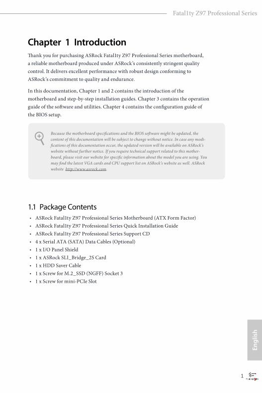
Chapter 1 IntroductionThank you for purchasing ASRock Fatal1ty Z97 Professional Series motherboard, a reliable motherboard produced under ASRock’s consistently stringent quality control. It delivers excellent performance with robust design conforming to ASRock’s commitment to quality and endurance.
In this documentation, Chapter 1 and 2 contains the introduction of the motherboard and step-by-step installation guides. Chapter 3 contains the operation guide of the software and utilities. Chapter 4 contains the configuration guide of the BIOS setup.
1.1 Package Contents• ASRock Fatal1ty Z97 Professional Series Motherboard (ATX Form Factor)• ASRock Fatal1ty Z97 Professional Series Quick Installation Guide • ASRock Fatal1ty Z97 Professional Series Support CD • 4 x Serial ATA (SATA) Data Cables (Optional)• 1 x I/O Panel Shield • 1 x ASRock SLI_Bridge_2S Card • 1 x HDD Saver Cable• 1 x Screw for M.2_SSD (NGFF) Socket 3 • 1 x Screw for mini-PCIe Slot
Because the motherboard specifications and the BIOS software might be updated, the content of this documentation will be subject to change without notice. In case any modi-fications of this documentation occur, the updated version will be available on ASRock’s website without further notice. If you require technical support related to this mother-board, please visit our website for specific information about the model you are using. You may find the latest VGA cards and CPU support list on ASRock’s website as well. ASRock website http://www.asrock.com.
2 3
English
Fatal1ty Z97 Professional Series
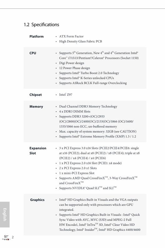
1.2 Specifications
Platform • ATX Form Factor• High Density Glass Fabric PCB
CPU • Supports 5th Generation, New 4th and 4th Generation Intel® Core™ i7/i5/i3/Pentium®/Celeron® Processors (Socket 1150)
• Digi Power design• 12 Power Phase design• Supports Intel® Turbo Boost 2.0 Technology• Supports Intel® K-Series unlocked CPUs• Supports ASRock BCLK Full-range Overclocking
Chipset • Intel® Z97
Memory • Dual Channel DDR3 Memory Technology• 4 x DDR3 DIMM Slots • Supports DDR3 3200+(OC)/2933
(OC)/2800(OC)/2400(OC)/2133(OC)/1866 (OC)/1600/ 1333/1066 non-ECC, un-buffered memory
• Max. capacity of system memory: 32GB (see CAUTION)• Supports Intel® Extreme Memory Profile (XMP) 1.3 / 1.2
Expansion Slot
• 3 x PCI Express 3.0 x16 Slots (PCIE2/PCIE4/PCIE6: single at x16 (PCIE2); dual at x8 (PCIE2) / x8 (PCIE4); triple at x8 (PCIE2) / x4 (PCIE4) / x4 (PCIE6)
• 1 x PCI Express 2.0 x16 Slot (PCIE1: x4 mode)• 2 x PCI Express 2.0 x1 Slots• 1 x mini-PCI Express Slot • Supports AMD Quad CrossFireXTM, 3-Way CrossFireXTM
and CrossFireXTM • Supports NVIDIA® Quad SLITM and SLITM
Graphics • Intel® HD Graphics Built-in Visuals and the VGA outputs can be supported only with processors which are GPU integrated.
• Supports Intel® HD Graphics Built-in Visuals : Intel® Quick Sync Video with AVC, MVC (S3D) and MPEG-2 Full HW Encode1, Intel® InTruTM 3D, Intel® Clear Video HD Technology, Intel® InsiderTM, Intel® HD Graphics 4400/4600
2 3
Engl
ish
Fatal1ty Z97 Professional Series
• Pixel Shader 5.0, DirectX 11.1 • Max. shared memory 1792MB • Dual graphics output: Support HDMI and DiaplayPort 1.2
ports by independent display controllers • Supports HDMI with max. resolution up to 4K x 2K
(4096x2304) @ 24Hz• Supports DisplayPort 1.2 with max. resolution up to 4K x 2K
(4096x2304) @ 24Hz or 4K x 2K (3840x2160) @ 60Hz• Supports Auto Lip Sync, Deep Color (12bpc), xvYCC and
HBR (High Bit Rate Audio) with HDMI Port (Compliant HDMI monitor is required)
• Supports HDCP with HDMI and DisplayPort 1.2 Ports • Supports Full HD 1080p Blu-ray (BD) playback with HDMI
and DisplayPort 1.2 Ports
Audio • 7.1 CH HD Audio • Supports Surge Protection (ASRock Full Spike Protection)• Nichicon Fine Gold Series Audio Caps• Creative Sound Core3D quad-core sound and voice
processor• Supports SBX Pro Studio• Supports CrystalVoice• Supports Scout Mode• Supports EAX1.0 to EAX5.0• Premium Headset Amplifier (PHA)
LAN • 1 x Intel® I218V (Gigabit LAN PHY 10/100/1000 Mb/s)• 1 x Qualcomm® Atheros® KillerTM E2200 Series (PCIE x1
Gigabit LAN 10/100/1000 Mb/s)• Supports Intel® Remote Wake Technology (on Intel® I218V)• Supports Qualcomm® Atheros® Security Wake On
Internet Technology (on Qualcomm® Atheros® KillerTM E2200 Series)
• Supports Wake-On-LAN • Supports Lightning/ESD Protection (ASRock Full Spike
Protection)• Supports Energy Efficient Ethernet 802.3az• Supports PXE
4 5
English
Fatal1ty Z97 Professional Series
Rear Panel I/O
• 1 x PS/2 Mouse/Keyboard Port• 1 x HDMI Port• 1 x DisplayPort 1.2• 1 x Optical SPDIF Out Port• 1 x eSATA Connector• 3 x USB 2.0 Ports (Supports ESD Protection (ASRock Full
Spike Protection))• 1 x Fatal1ty Mouse Port (USB 2.0) (Supports ESD Protection
(ASRock Full Spike Protection))• 4 x USB 3.0 Ports (Supports ESD Protection (ASRock Full
Spike Protection)) • 2 x RJ-45 LAN Ports with LED (ACT/LINK LED and SPEED
LED)• 1 x Clear CMOS Switch • HD Audio Jacks: Rear Speaker / Central / Bass / Line in /
Front Speaker / Microphone
Storage • 6 x SATA3 6.0 Gb/s Connectors by Intel® Z97, support RAID (RAID 0, RAID 1, RAID 5, RAID 10, Intel Rapid Storage Technology 13 and Intel Smart Response Technology), NCQ, AHCI, Hot Plug and ASRock HDD Saver Technology
• 2 x SATA3 6.0 Gb/s Connectors by ASMedia ASM1061, support NCQ, AHCI, Hot Plug and ASRock HDD Saver Technology (SATA3_A2 connector is shared with the eSATA port)
• 2 x SATA Express Connectors (SATAE_0 is shared with SATA3_1 and SATA3_2; SATAE_1 is shared with SATA3_4, SATA3_5 and M.2 Socket) * Support to be announced
• 1 x eSATA Connector by ASMedia ASM1061, supports NCQ, AHCI and Hot Plug
• 1 x M.2_SSD (NGFF) Socket 3, supports M.2 SATA3 6.0 Gb/s module and M.2 PCI Express module up to Gen2 x2 (10 Gb/s)
Connector • 1 x COM Port Header• 1 x TPM Header• 1 x Power LED Header• 2 x CPU Fan Connectors (1 x 4-pin, 1 x 3-pin)
4 5
Engl
ish
Fatal1ty Z97 Professional Series
• 3 x Chassis Fan Connectors (1 x 4-pin, 2 x 3-pin)• 1 x Power Fan Connector (3-pin)• 1 x 24 pin ATX Power Connector• 1 x 8 pin 12V Power Connector (Hi-Density Power
Connector)• 1 x HDD Saver Connector• 1 x PCIe Power Connector• 1 x Front Panel Audio Connector• 1 x Thunderbolt AIC Connector• 2 x USB 2.0 Headers (Support 4 USB 2.0 ports) (Supports
ESD Protection (ASRock Full Spike Protection))• 2 x USB 3.0 Headers (Support 4 USB 3.0 ports) (ASMedia
ASM1074 hub) (Supports ESD Protection (ASRock Full Spike Protection))
• 1 x Dr. Debug with LED• 1 x Power Switch with LED• 1 x Reset Switch with LED• 1 x BIOS Selection Switch
BIOS Feature
• 2 x 64Mb AMI UEFI Legal BIOS with multilingual GUI sup-port (1 x Main BIOS and 1 x Backup BIOS)
• Supports Secure Backup UEFI Technology• ACPI 1.1 Compliant wake up events• SMBIOS 2.3.1 Support• CPU, DRAM, PCH 1.05V, PCH 1.5V Voltage Multi-adjust-
ment
Hardware Monitor
• CPU/Chassis temperature sensing• CPU/Chassis/Power Fan Tachometer• CPU/Chassis Quiet Fan (Auto adjust chassis fan speed by
CPU temperature)• CPU/Chassis Fan multi-speed control• Voltage monitoring: +12V, +5V, +3.3V, CPU Input Voltage,
CPU Internal Voltages
OS • Microsoft® Windows® 8.1 32-bit / 8.1 64-bit / 8 32-bit / 8 64-bit / 7 32-bit / 7 64-bit
6 7
English
Fatal1ty Z97 Professional Series
Certifica-tions
• FCC, CE, WHQL• ErP/EuP Ready (ErP/EuP ready power supply is required)
Please realize that there is a certain risk involved with overclocking, including adjusting the setting in the BIOS, applying Untied Overclocking Technology, or using third-party overclocking tools. Overclocking may affect your system’s stability, or even cause damage to the components and devices of your system. It should be done at your own risk and expense. We are not responsible for possible damage caused by overclocking.
* For detailed product information, please visit our website: http://www.asrock.com
Due to limitation, the actual memory size may be less than 4GB for the reservation for sys-tem usage under Windows® 32-bit operating systems. Windows® 64-bit operating systems do not have such limitations. You can use ASRock XFast RAM to utilize the memory that Windows® cannot use.
6 7
Engl
ish
Fatal1ty Z97 Professional Series
IntelZ97
DD
R3
_A
2 (
64
bit
, 2
40
-pin
mo
du
le)
DD
R3
_A
1 (
64
bit
, 2
40
-pin
mo
du
le)
DD
R3
_B
2 (
64
bit
, 2
40
-pin
mo
du
le)
DD
R3
_B
1 (
64
bit
, 2
40
-pin
mo
du
le)
ATX12V1
US
B 2
.0T: U
SB
0B
: US
B1
PS
2K
ey
bo
ard
/M
ou
se
AT
XP
WR
1
1
US
B3
_4
_5
1
US
B3
_6
_7
PCIE2
PCIE1
Top:RJ-45
USB 3.0T: USB2B: USB3
Top
:C
en
tral/B
as
s
Ce
nte
r:R
EA
R S
PK
To
p:
LIN
E IN
Ce
nte
r:F
RO
NT
Bo
ttom
:O
ptic
al
SP
DIF
Bo
ttom
:M
IC IN
Z97 Professional
PCIE5
PCIE3
CHA_FAN2
RoHS
9
8
10
12
13
14
15
16
CPU_FAN1
2 3
7
6
5
41
34
BIOS_SEL1
1
KillerE2200
PCIE4
PCIE_PWR1
SA
TA3
_0
SA
TA3
_3
SA
TA3
_A
1
SA
TA3
_A
2
36
CPU_FAN2
PWR_FAN1
SATA_PWR_1
1
64MbBIOS
BIOS_A
BIOS_A_LED
64MbBIOS
BIOS_B
BIOS_B_LED
1TPMS1
CMOSBattery
M2
_2
NUT1NUT2NUT3NUT4NUT5
SA
TA3
_1
SA
TA3
_4
SA
TA3
_
SA
TA3
_2
SA
TA3
_5
SA
TA3
_5
SA
TAE
_1
SA
TAE
_0
37
11
21
CHA_FAN1
FATAL TY1
CLRCMOS1
1
PLED1
1 1
SPEAKER1
USB4_5
1
USB6_7
1
COM1
11
HD_AUDIO1
PCIE6
2225
HDLED RESET
PLED PWRBTN
PANEL1
1
262730 2829313233 2324
PowerReset
Dr.Debug
T B1
1
SuperI/O
35
HD
MI1
DP
_1
ClrCMOS
Top:RJ-45
USB 3.0T: USB0B: USB1
US
B 2
.0T: U
SB
2B
: US
B3
eS
AT
A_
1
LAN
MIN
I_P
CIE
1
17
18
19
20
SoundCORE3D
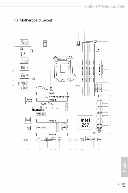
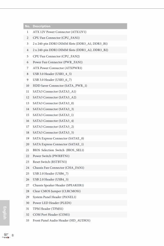
1.3 Motherboard Layout
8 9
English
Fatal1ty Z97 Professional Series
No. Description
1 ATX 12V Power Connector (ATX12V1)
2 CPU Fan Connector (CPU_FAN1)
3 2 x 240-pin DDR3 DIMM Slots (DDR3_A1, DDR3_B1)
4 2 x 240-pin DDR3 DIMM Slots (DDR3_A2, DDR3_B2)
5 CPU Fan Connector (CPU_FAN2)
6 Power Fan Connector (PWR_FAN1)
7 ATX Power Connector (ATXPWR1)
8 USB 3.0 Header (USB3_4_5)
9 USB 3.0 Header (USB3_6_7)
10 HDD Saver Connector (SATA_PWR_1)
11 SATA3 Connector (SATA3_A1)
12 SATA3 Connector (SATA3_A2)
13 SATA3 Connector (SATA3_0)
14 SATA3 Connector (SATA3_3)
15 SATA3 Connector (SATA3_1)
16 SATA3 Connector (SATA3_4)
17 SATA3 Connector (SATA3_2)
18 SATA3 Connector (SATA3_5)
19 SATA Express Connector (SATAE_0)
20 SATA Express Connector (SATAE_1)
21 BIOS Selection Switch (BIOS_SEL1)
22 Power Switch (PWRBTN1)
23 Reset Switch (RSTBTN1)
24 Chassis Fan Connector (CHA_FAN1)
25 USB 2.0 Header (USB6_7)
26 USB 2.0 Header (USB4_5)
27 Chassis Speaker Header (SPEAKER1)
28 Clear CMOS Jumper (CLRCMOS1)
29 System Panel Header (PANEL1)
30 Power LED Header (PLED1)
31 TPM Header (TPMS1)
32 COM Port Header (COM1)
33 Front Panel Audio Header (HD_AUDIO1)

8 9
Engl
ish
Fatal1ty Z97 Professional Series
No. Description
34 PCIe Power Connector (PCIE_PWR1)
35 Thunderbolt AIC Connector (TB1)
36 Chassis Fan Connector (CHA_FAN2)
37 Chassis Fan Connector (CHA_FAN3)
10 11
English
Fatal1ty Z97 Professional Series
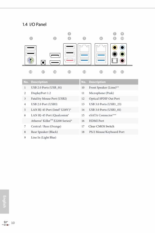
1.4 I/O Panel
No. Description No. Description
1 USB 2.0 Ports (USB_01) 10 Front Speaker (Lime)**
2 DisplayPort 1.2 11 Microphone (Pink)
3 Fatal1ty Mouse Port (USB2) 12 Optical SPDIF Out Port
4 USB 2.0 Port (USB3) 13 USB 3.0 Ports (USB3_23)
5 LAN RJ-45 Port (Intel® I218V)* 14 USB 3.0 Ports (USB3_01)
6 LAN RJ-45 Port (Qualcomm® 15 eSATA Connector***
Atheros® KillerTM E2200 Series)* 16 HDMI Port
7 Central / Bass (Orange) 17 Clear CMOS Switch
8 Rear Speaker (Black) 18 PS/2 Mouse/Keyboard Port
9 Line In (Light Blue)
21 6 8
111218 13151617
743
109
5
14
10 11
Engl
ish
Fatal1ty Z97 Professional Series
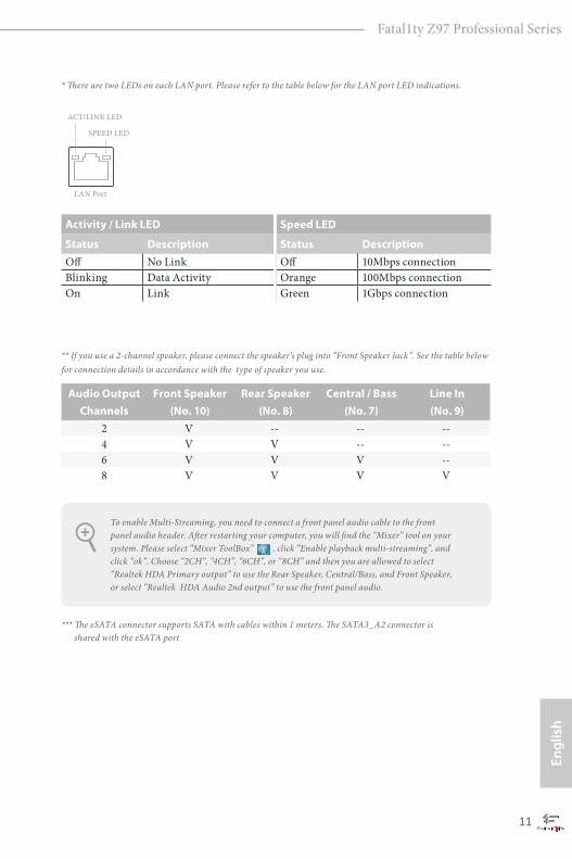
* There are two LEDs on each LAN port. Please refer to the table below for the LAN port LED indications.
Activity / Link LED Speed LED
Status Description Status DescriptionOff No Link Off 10Mbps connectionBlinking Data Activity Orange 100Mbps connectionOn Link Green 1Gbps connection
** If you use a 2-channel speaker, please connect the speaker’s plug into “Front Speaker Jack”. See the table below for connection details in accordance with the type of speaker you use.
Audio Output Channels
Front Speaker(No. 10)
Rear Speaker(No. 8)
Central / Bass(No. 7)
Line In(No. 9)
2 V -- -- --4 V V -- --6 V V V --8 V V V V
*** The eSATA connector supports SATA with cables within 1 meters. The SATA3_A2 connector is shared with the eSATA port
To enable Multi-Streaming, you need to connect a front panel audio cable to the front panel audio header. After restarting your computer, you will find the “Mixer” tool on your system. Please select “Mixer ToolBox” , click “Enable playback multi-streaming”, and click “ok”. Choose “2CH”, “4CH”, “6CH”, or “8CH” and then you are allowed to select “Realtek HDA Primary output” to use the Rear Speaker, Central/Bass, and Front Speaker, or select “Realtek HDA Audio 2nd output” to use the front panel audio.
ACT/LINK LED
SPEED LED
LAN Port
12 13
English
Fatal1ty Z97 Professional Series
This is an ATX form factor motherboard. Before you install the motherboard, study the configuration of your chassis to ensure that the motherboard fits into it.
Pre-installation PrecautionsTake note of the following precautions before you install motherboard components or change any motherboard settings.
• Make sure to unplug the power cord before installing or removing the motherboard components. Failure to do so may cause physical injuries and damages to motherboard components.
• In order to avoid damage from static electricity to the motherboard’s components, NEVER place your motherboard directly on a carpet. Also remember to use a grounded wrist strap or touch a safety grounded object before you handle the components.
• Hold components by the edges and do not touch the ICs.• Whenever you uninstall any components, place them on a grounded anti-static pad or
in the bag that comes with the components.• When placing screws to secure the motherboard to the chassis, please do not over-
tighten the screws! Doing so may damage the motherboard.
Chapter 2 Installation
12 13
Engl
ish
Fatal1ty Z97 Professional Series
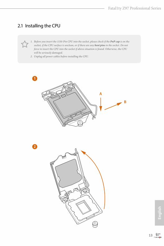
2.1 Installing the CPU
1. Before you insert the 1150-Pin CPU into the socket, please check if the PnP cap is on the socket, if the CPU surface is unclean, or if there are any bent pins in the socket. Do not force to insert the CPU into the socket if above situation is found. Otherwise, the CPU will be seriously damaged.
2. Unplug all power cables before installing the CPU.
2
1
A
B
14 15
English
Fatal1ty Z97 Professional Series
4
5
3

14 15
Engl
ish
Fatal1ty Z97 Professional Series
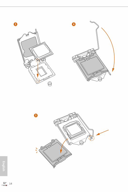
Please save and replace the cover if the processor is removed. The cover must be placed if you wish to return the motherboard for after service.
16 17
English
Fatal1ty Z97 Professional Series
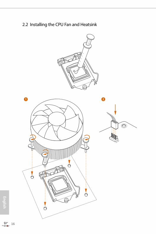
2.2 Installing the CPU Fan and Heatsink
1 2
CPU_FAN
16 17
Engl
ish
Fatal1ty Z97 Professional Series
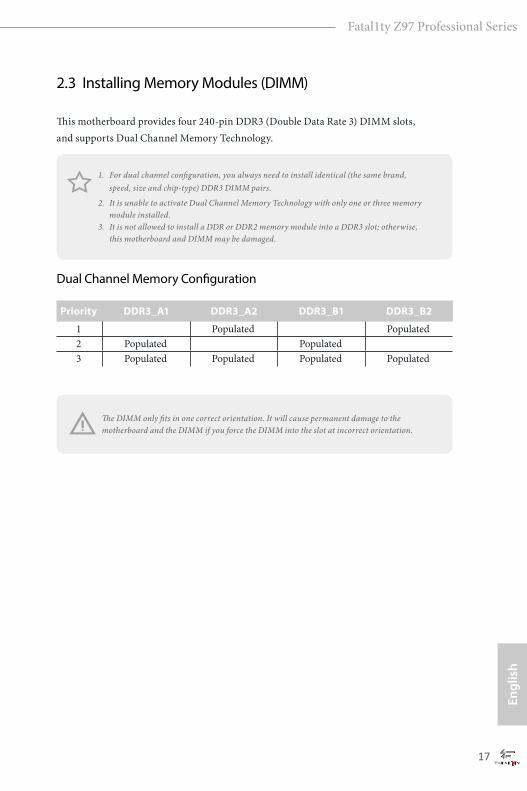
2.3 Installing Memory Modules (DIMM)
This motherboard provides four 240-pin DDR3 (Double Data Rate 3) DIMM slots, and supports Dual Channel Memory Technology.
Dual Channel Memory Configuration
The DIMM only fits in one correct orientation. It will cause permanent damage to the motherboard and the DIMM if you force the DIMM into the slot at incorrect orientation.
Priority DDR3_A1 DDR3_A2 DDR3_B1 DDR3_B2
1 Populated Populated 2 Populated Populated 3 Populated Populated Populated Populated
1. For dual channel configuration, you always need to install identical (the same brand, speed, size and chip-type) DDR3 DIMM pairs.
2. It is unable to activate Dual Channel Memory Technology with only one or three memory module installed.
3. It is not allowed to install a DDR or DDR2 memory module into a DDR3 slot; otherwise, this motherboard and DIMM may be damaged.
18 19
English
Fatal1ty Z97 Professional Series
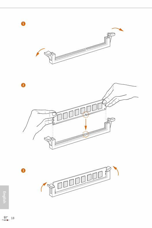
1
2
3
18 19
Engl
ish
Fatal1ty Z97 Professional Series
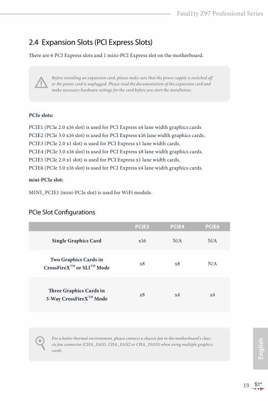
2.4 Expansion Slots (PCI Express Slots)There are 6 PCI Express slots and 1 mini-PCI Express slot on the motherboard.
PCIe slots:
PCIE1 (PCIe 2.0 x16 slot) is used for PCI Express x4 lane width graphics cards PCIE2 (PCIe 3.0 x16 slot) is used for PCI Express x16 lane width graphics cards. PCIE3 (PCIe 2.0 x1 slot) is used for PCI Express x1 lane width cards. PCIE4 (PCIe 3.0 x16 slot) is used for PCI Express x8 lane width graphics cards. PCIE5 (PCIe 2.0 x1 slot) is used for PCI Express x1 lane width cards. PCIE6 (PCIe 3.0 x16 slot) is used for PCI Express x4 lane width graphics cards.
mini-PCIe slot:
MINI_PCIE1 (mini-PCIe slot) is used for WiFi module.
PCIe Slot Configurations
For a better thermal environment, please connect a chassis fan to the motherboard’s chas-sis fan connector (CHA_FAN1, CHA_FAN2 or CHA_FAN3) when using multiple graphics cards.
Before installing an expansion card, please make sure that the power supply is switched off or the power cord is unplugged. Please read the documentation of the expansion card and make necessary hardware settings for the card before you start the installation.
PCIE2 PCIE4 PCIE6
Single Graphics Card x16 N/A N/A
Two Graphics Cards in CrossFireXTM or SLITM Mode
x8 x8 N/A
Three Graphics Cards in 3-Way CrossFireXTM Mode
x8 x4 x4
20 21
English
Fatal1ty Z97 Professional Series
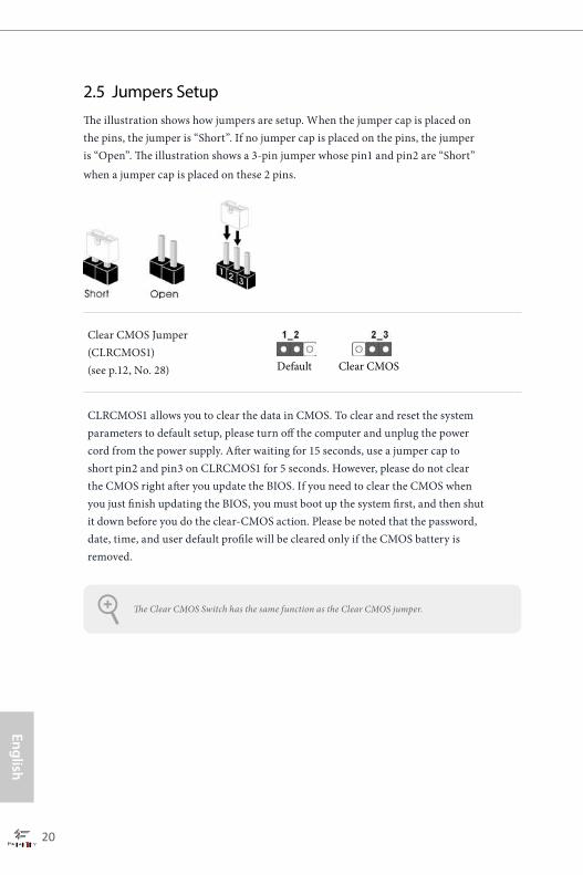
2.5 Jumpers SetupThe illustration shows how jumpers are setup. When the jumper cap is placed on the pins, the jumper is “Short”. If no jumper cap is placed on the pins, the jumper is “Open”. The illustration shows a 3-pin jumper whose pin1 and pin2 are “Short” when a jumper cap is placed on these 2 pins.
Clear CMOS Jumper(CLRCMOS1)(see p.12, No. 28)
CLRCMOS1 allows you to clear the data in CMOS. To clear and reset the system parameters to default setup, please turn off the computer and unplug the power cord from the power supply. After waiting for 15 seconds, use a jumper cap to short pin2 and pin3 on CLRCMOS1 for 5 seconds. However, please do not clear the CMOS right after you update the BIOS. If you need to clear the CMOS when you just finish updating the BIOS, you must boot up the system first, and then shut it down before you do the clear-CMOS action. Please be noted that the password, date, time, and user default profile will be cleared only if the CMOS battery is removed.
Clear CMOSDefault
The Clear CMOS Switch has the same function as the Clear CMOS jumper.
20 21
Engl
ish
Fatal1ty Z97 Professional Series
2.6 Onboard Headers and Connectors
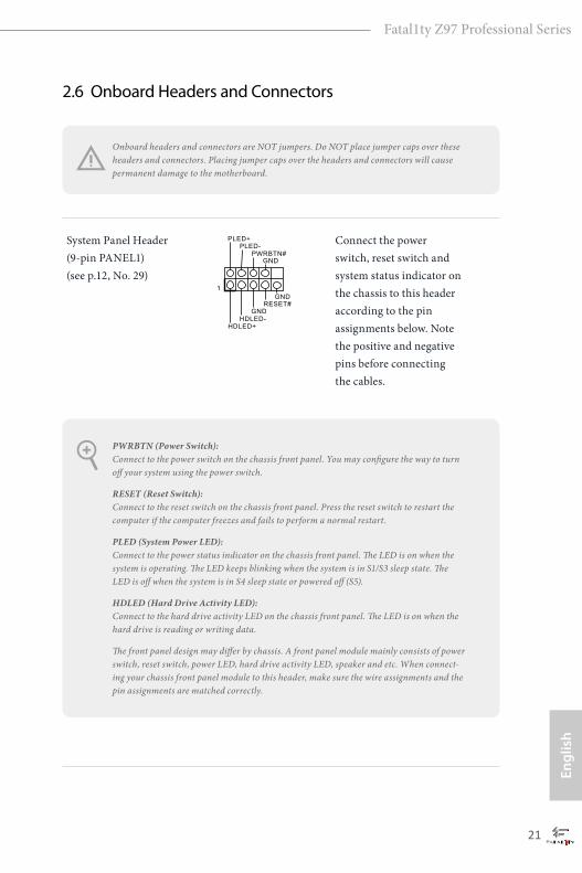
System Panel Header(9-pin PANEL1)(see p.12, No. 29)
Connect the power switch, reset switch and system status indicator on the chassis to this header according to the pin assignments below. Note the positive and negative pins before connecting the cables.
GND
RESET#
PWRBTN#
PLED-
PLED+
GND
HDLED-
HDLED+
1
GND
PWRBTN (Power Switch): Connect to the power switch on the chassis front panel. You may configure the way to turn off your system using the power switch.
RESET (Reset Switch): Connect to the reset switch on the chassis front panel. Press the reset switch to restart the computer if the computer freezes and fails to perform a normal restart.
PLED (System Power LED): Connect to the power status indicator on the chassis front panel. The LED is on when the system is operating. The LED keeps blinking when the system is in S1/S3 sleep state. The LED is off when the system is in S4 sleep state or powered off (S5).
HDLED (Hard Drive Activity LED): Connect to the hard drive activity LED on the chassis front panel. The LED is on when the hard drive is reading or writing data.
The front panel design may differ by chassis. A front panel module mainly consists of power switch, reset switch, power LED, hard drive activity LED, speaker and etc. When connect-ing your chassis front panel module to this header, make sure the wire assignments and the pin assignments are matched correctly.
Onboard headers and connectors are NOT jumpers. Do NOT place jumper caps over these headers and connectors. Placing jumper caps over the headers and connectors will cause permanent damage to the motherboard.
22 23
English
Fatal1ty Z97 Professional Series
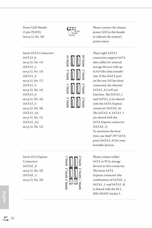
Power LED Header(3-pin PLED1)(see p.12, No. 30)
Please connect the chassis power LED to this header to indicate the system’s power status.
Serial ATA3 Connectors(SATA3_0: see p.12, No. 13)(SATA3_1: see p.12, No. 15) (SATA3_2: see p.12, No. 17) (SATA3_3: see p.12, No. 14) (SATA3_4: see p.12, No. 16) (SATA3_5: see p.12, No. 18) (SATA3_A1: see p.12, No. 11) (SATA3_A2: see p.12, No. 12)
These eight SATA3 connectors support SATA data cables for internal storage devices with up to 6.0 Gb/s data transfer rate. If the eSATA port on the rear I/O has been connected, the internal SATA3_A2 will not function. The SATA3_1 and SATA3_2 are shared with the SATA Express connector (SATAE_0). The SATA3_4, SATA3_5 are shared with the SATA Express connector (SATAE_1). To minimize the boot time, use Intel® Z97 SATA ports (SATA3_0) for your bootable devices.
Serial ATA Express Connectors(SATAE_0: see p.12, No. 19) (SATAE_1: see p.12, No. 20)
Please connect either SATA or PCIe storage devices to this connector. The lower SATA Express connector (the combination of SATAE_1, SATA3_5, and SATA3_4)is shared with the M.2_SSD (NGFF) Socket 3.
1
PLED+
PLED+
PLED-
SATA
3_A1
SATA
3_0
SATA
3_1
SATA
3_1
SATA
3_4
SATA
3_2
SATA
3_2
SATA
3_5
SATA
3_A2
SATA
3_3
SATA
3_4
SATA
3_5
SATA
E_1
SATA
E_0

22 23
Engl
ish
Fatal1ty Z97 Professional Series
DUMMYGND
GND
P+P-
USB_PWR
P+P-
USB_PWR
1
USB 2.0 Headers(9-pin USB4_5)(see p.12, No. 26)(9-pin USB6_7)(see p.12, No. 25)
There are two headers on this motherboard. Each USB 2.0 header can support two ports.
USB 3.0 Headers(19-pin USB3_4_5)(see p.12, No. 8)(19-pin USB3_6_7)(see p.12, No. 9)
Besides four USB 3.0 ports on the I/O panel, there are two headers on this motherboard. Each USB 3.0 header can support two ports.
Front Panel Audio Header(9-pin HD_AUDIO1)(see p.12, No. 33)
This header is for connecting audio devices to the front audio panel.
Chassis Speaker Header(4-pin SPEAKER1)(see p.12, No. 27)
Please connect the chassis speaker to this header.
1
IntA_PB_D+
Dummy
IntA_PB_D-
GND
IntA_PB_SSTX+
GND
IntA_PB_SSTX-
IntA_PB_SSRX+
IntA_PB_SSRX-
VbusVbus
Vbus
IntA_PA_SSRX-
IntA_PA_SSRX+
GND
IntA_PA_SSTX-
IntA_PA_SSTX+
GND
IntA_PA_D-
IntA_PA_D+
J_SENSE
OUT2_L
1
MIC_RETPRESENCE#
GND
OUT2_RMIC2_R
MIC2_L
OUT_RET
1
+5V
DUMMY
DUMMY
SPEAKER
1. High Definition Audio supports Jack Sensing, but the panel wire on the chassis must sup-port HDA to function correctly. Please follow the instructions in our manual and chassis manual to install your system.
2. If you use an AC’97 audio panel, please install it to the front panel audio header by the steps below: A. Connect Mic_IN (MIC) to MIC2_L. B. Connect Audio_R (RIN) to OUT2_R and Audio_L (LIN) to OUT2_L. C. Connect Ground (GND) to Ground (GND). D. MIC_RET and OUT_RET are for the HD audio panel only. You don’t need to connect them for the AC’97 audio panel. E. To activate the front mic, go to the “FrontMic” Tab in the Realtek Control panel and adjust “Recording Volume”.
24 25
English
Fatal1ty Z97 Professional Series
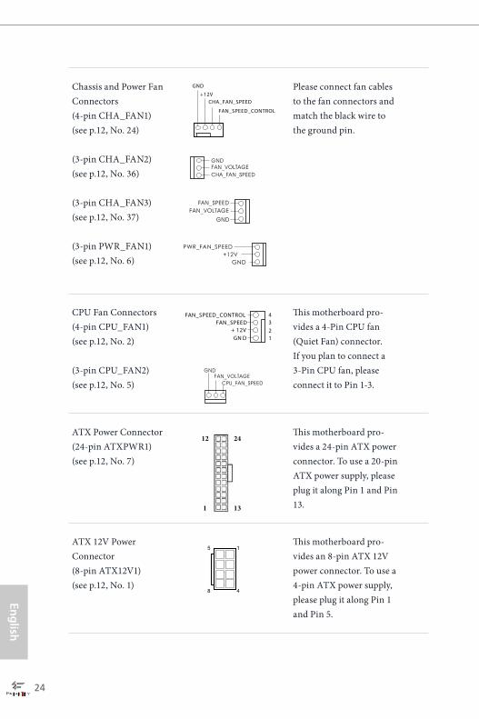
Chassis and Power Fan Connectors(4-pin CHA_FAN1)(see p.12, No. 24)
(3-pin CHA_FAN2)(see p.12, No. 36)
(3-pin CHA_FAN3)(see p.12, No. 37)
(3-pin PWR_FAN1)(see p.12, No. 6)
Please connect fan cables to the fan connectors and match the black wire to the ground pin.
CPU Fan Connectors(4-pin CPU_FAN1)(see p.12, No. 2)
(3-pin CPU_FAN2)(see p.12, No. 5)
This motherboard pro-vides a 4-Pin CPU fan (Quiet Fan) connector. If you plan to connect a 3-Pin CPU fan, please connect it to Pin 1-3.
ATX Power Connector(24-pin ATXPWR1)(see p.12, No. 7)
This motherboard pro-vides a 24-pin ATX power connector. To use a 20-pin ATX power supply, please plug it along Pin 1 and Pin 13.
ATX 12V Power Connector(8-pin ATX12V1)(see p.12, No. 1)
This motherboard pro-vides an 8-pin ATX 12V power connector. To use a 4-pin ATX power supply, please plug it along Pin 1 and Pin 5.
GND
+12VCHA_FAN_SPEED
FAN_SPEED_CONTROL
GND
FAN_SPEEDFAN_VOLTAGE
GND
CHA_FAN_SPEEDFAN_VOLTAGE
GND
CPU_FAN_SPEEDFAN_VOLTAGE
GN D+ 12V
FAN_SPEEDFAN_SPEED_CONTROL
1234
12
1
24
13
5
8
1
4
24 25
Engl
ish
Fatal1ty Z97 Professional Series
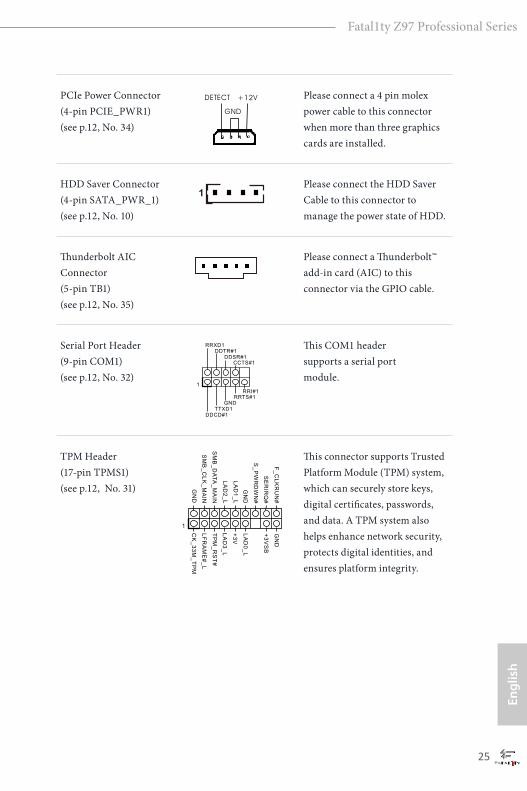
PCIe Power Connector(4-pin PCIE_PWR1) (see p.12, No. 34)
Please connect a 4 pin molex power cable to this connector when more than three graphics cards are installed.
HDD Saver Connector(4-pin SATA_PWR_1) (see p.12, No. 10)
Please connect the HDD Saver Cable to this connector to manage the power state of HDD.
Thunderbolt AIC Connector(5-pin TB1) (see p.12, No. 35)
Please connect a Thunderbolt™ add-in card (AIC) to this connector via the GPIO cable.
Serial Port Header(9-pin COM1)(see p.12, No. 32)
This COM1 header supports a serial port module.
TPM Header(17-pin TPMS1)(see p.12, No. 31)
This connector supports Trusted Platform Module (TPM) system, which can securely store keys, digital certificates, passwords, and data. A TPM system also helps enhance network security, protects digital identities, and ensures platform integrity.
1
CCTS#1
RRTS#1
DDSR#1
DDTR#1
RRXD1
GND
TTXD1
DDCD#1
1
RRI#1
1
LF
RA
ME
#_
L
CK
_3
3M
_T
PM
TP
M_
RS
T#
LA
D3
_L
+3
V
LA
D0
_L
+3
VS
B
GN
DF
_C
LK
RU
N#
SE
RIR
Q#
S_
PW
RD
WN
#
GN
D
LA
D1
_L
LA
D2
_L
SM
B_
DA
TA
_M
AIN
SM
B_
CL
K_
MA
IN
GN
D

26 27
English
Fatal1ty Z97 Professional Series
2.7 Smart SwitchesThe motherboard has four smart switches: Power Switch, Reset Switch, Clear CMOS Switch and one BIOS Selection Switch, allowing users to quickly turn on/off the system, reset the system, clear the CMOS values or boot from different BIOS.
Power Switch(PWRBTN)(see p.12, No. 22)
Power Switch allows users to quickly turn on/off the system.
Reset Switch(RSTBTN)(see p.12, No. 23)
Reset Switch allows users to quickly reset the system.
Clear CMOS Switch(CLRCBTN)(see p.15, No. 17)
Clear CMOS Switch allows users to quickly clear the CMOS values.
BIOS Selection Switch (BIOS_SEL1) (see p.12 No. 21)
BIOS Selection Switch allows the system to boot from either BIOS A or BIOS B.
Power
Reset
This function is workable only when you power off your computer and unplug the power supply.
A B
This motherboard has two BIOS chips, a primary BIOS (BIOS_A) and a backup BIOS (BIOS_B), which enhances the safety and stability of your system. Normally, the system will work on the primary BIOS. However, if the primary BIOS is corrupted or damaged, just flip the BIOS Selection Switch to “B”, then the backup BIOS will take over on the next system boot. After that, use “Secure Backup UEFI” in the UEFI Setup Utility to duplicate a working copy of the BIOS files to the primary BIOS to ensure normal system operation. For safety issues, users are not able to update the backup BIOS manually. Users may refer to the BIOS LEDs (BIOS_A_LED or BIOS_B_LED) to identify which BIOS is currently activated.

26 27
Engl
ish
Fatal1ty Z97 Professional Series
2.8 Dr. DebugDr. Debug is used to provide code information, which makes troubleshooting even easier. Please see the diagrams below for reading the Dr. Debug codes.
Code Description
00 Please check if the CPU is installed correctly and then clear CMOS.
0d Problem related to memory, VGA card or other devices. Please clear CMOS, re-install the memory and VGA card, and remove other USB, PCI devices.
01 - 54 (except 0d), 5A- 60
Problem related to memory. Please re-install the CPU andmemory then clear CMOS. If the problem still exists, please install only one memory module or try using other memory modules.
55 The Memory could not be detected. Please re-install the memory and CPU. If the problem still exists, please install only one memory module or try using other memory modules.
61 - 91 Chipset initialization error. Please press reset or clear CMOS.
92 - 99 Problem related to PCI-E devices. Please re-install PCI-E devices or try installing them in other slots. If the problem still exists, please remove all PCI-E devices or try using another VGA card.
A0 - A7 Problem related to IDE or SATA devices. Please re-install IDE and SATA devices. If the problem still exists, please clear CMOS and try removing all SATA devices.
b0 Problem related to memory. Please re-install the CPU and memory. If the problem still exists, please install only one memory module or try using other memory modules.
28 29
English
Fatal1ty Z97 Professional Series
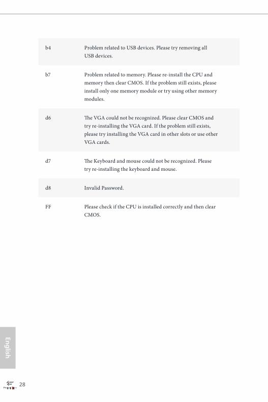
b4 Problem related to USB devices. Please try removing all USB devices.
b7 Problem related to memory. Please re-install the CPU and memory then clear CMOS. If the problem still exists, please install only one memory module or try using other memory modules.
d6 The VGA could not be recognized. Please clear CMOS and try re-installing the VGA card. If the problem still exists, please try installing the VGA card in other slots or use other VGA cards.
d7 The Keyboard and mouse could not be recognized. Please try re-installing the keyboard and mouse.
d8 Invalid Password.
FF Please check if the CPU is installed correctly and then clear CMOS.
28 29
Engl
ish
Fatal1ty Z97 Professional Series
2.9 SLITM and Quad SLITM Operation GuideThis motherboard supports NVIDIA® SLITM and Quad SLITM (Scalable Link Interface) technology that allows you to install up to two identical PCI Express x16 graphics cards. Currently, NVIDIA® SLITM and Quad SLITM technology supports Windows® 7 / 7 64-bit / 8 / 8 64-bit / 8.1 / 8.1 64-bit OS.
2.9.1 Installing Two SLITM-Ready Graphics Cards
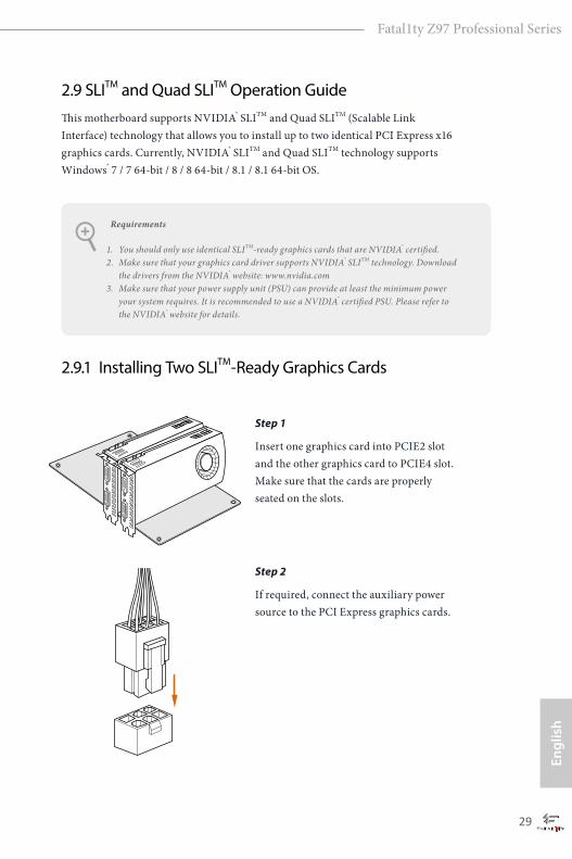
Step 1
Insert one graphics card into PCIE2 slot and the other graphics card to PCIE4 slot. Make sure that the cards are properly seated on the slots.
Step 2
If required, connect the auxiliary power source to the PCI Express graphics cards.
Requirements
1. You should only use identical SLITM-ready graphics cards that are NVIDIA® certified.2. Make sure that your graphics card driver supports NVIDIA® SLITM technology. Download
the drivers from the NVIDIA® website: www.nvidia.com3. Make sure that your power supply unit (PSU) can provide at least the minimum power
your system requires. It is recommended to use a NVIDIA® certified PSU. Please refer to the NVIDIA® website for details.
30 31
English
Fatal1ty Z97 Professional Series
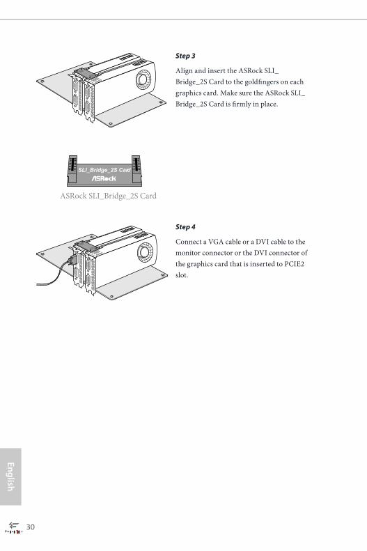
Step 3
Align and insert the ASRock SLI_Bridge_2S Card to the goldfingers on each graphics card. Make sure the ASRock SLI_Bridge_2S Card is firmly in place.
Step 4
Connect a VGA cable or a DVI cable to the monitor connector or the DVI connector of the graphics card that is inserted to PCIE2 slot.
ASRock SLI_Bridge_2S Card
SLI_Bridge_2S Card
30 31
Engl
ish
Fatal1ty Z97 Professional Series
2.9.2 Driver Installation and Setup
Install the graphics card drivers to your system. After that, you can enable the Multi-Graphics Processing Unit (GPU) in the NVIDIA® nView system tray utility. Please follow the below procedures to enable the multi-GPU.
For SLITM and Quad SLITM mode
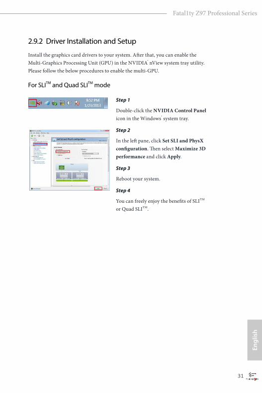
Step 1
Double-click the NVIDIA Control Panel icon in the Windows® system tray.
Step 2
In the left pane, click Set SLI and PhysX configuration. Then select Maximize 3D performance and click Apply.
Step 3
Reboot your system.
Step 4
You can freely enjoy the benefits of SLITM or Quad SLITM.

32 33
English
Fatal1ty Z97 Professional Series
2.10 CrossFireXTM, 3-Way CrossFireXTM and Quad CrossFireXTM Operation GuideThis motherboard supports CrossFireXTM, 3-way CrossFireXTM and Quad CrossFireXTM that allows you to install up to three identical PCI Express x16 graphics cards. Currently CrossFireXTM, 3-way CrossFireXTM and Quad CrossFireXTM are supported with Windows® 7 / 7 64-bit / 8 / 8 64-bit / 8.1 / 8.1 64-bit OS.
2.10.1 Installing Two CrossFireXTM-Ready Graphics Cards
Step 1
Insert one graphics card into PCIE2 slot and the other graphics card to PCIE4 slot. Make sure that the cards are properly seated on the slots.
Step 2
Connect two graphics cards by installing a CrossFire Bridge on the CrossFire Bridge Interconnects on the top of the graphics cards. (The CrossFire Bridge is provided with the graphics card you purchase, not bundled with this motherboard. Please refer to your graphics card vendor for details.)
1. You should only use identical CrossFireXTM-ready graphics cards that are AMD certified.
2. Make sure that your graphics card driver supports AMD CrossFireXTM technology. Download the drivers from the AMD’s website: www.amd.com
3. Make sure that your power supply unit (PSU) can provide at least the minimum power your system requires. It is recommended to use a AMD certified PSU. Please refer to the AMD’s website for details.
4. If you pair a 12-pipe CrossFireXTM Edition card with a 16-pipe card, both cards will operate as 12-pipe cards while in CrossFireXTM mode.
5. Different CrossFireXTM cards may require different methods to enable CrossFi-reXTM. Please refer to AMD graphics card manuals for detailed installation guide.
CrossFire Bridge
32 33
Engl
ish
Fatal1ty Z97 Professional Series
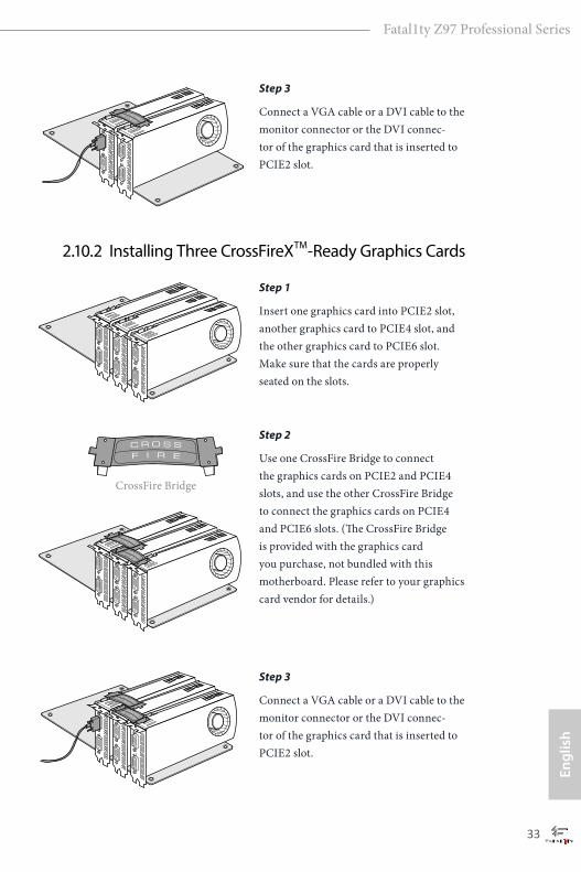
2.10.2 Installing Three CrossFireXTM-Ready Graphics Cards
Step 3
Connect a VGA cable or a DVI cable to the monitor connector or the DVI connec-tor of the graphics card that is inserted to PCIE2 slot.
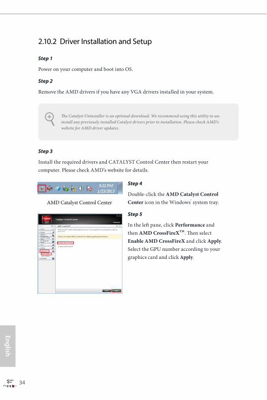
Step 1
Insert one graphics card into PCIE2 slot, another graphics card to PCIE4 slot, and the other graphics card to PCIE6 slot. Make sure that the cards are properly seated on the slots.
Step 2
Use one CrossFire Bridge to connect the graphics cards on PCIE2 and PCIE4 slots, and use the other CrossFire Bridge to connect the graphics cards on PCIE4 and PCIE6 slots. (The CrossFire Bridge is provided with the graphics card you purchase, not bundled with this motherboard. Please refer to your graphics card vendor for details.)
Step 3
Connect a VGA cable or a DVI cable to the monitor connector or the DVI connec-tor of the graphics card that is inserted to PCIE2 slot.
CrossFire Bridge
34 35
English
Fatal1ty Z97 Professional Series
Step 1
Power on your computer and boot into OS.
Step 2
Remove the AMD drivers if you have any VGA drivers installed in your system.
Step 3
Install the required drivers and CATALYST Control Center then restart your computer. Please check AMD’s website for details.
2.10.2 Driver Installation and Setup
Step 4
Double-click the AMD Catalyst Control Center icon in the Windows® system tray.
Step 5
In the left pane, click Performance and then AMD CrossFireXTM. Then select Enable AMD CrossFireX and click Apply.Select the GPU number according to your graphics card and click Apply.
AMD Catalyst Control Center
The Catalyst Uninstaller is an optional download. We recommend using this utility to un-install any previously installed Catalyst drivers prior to installation. Please check AMD’s website for AMD driver updates.
34 35
Engl
ish
Fatal1ty Z97 Professional Series
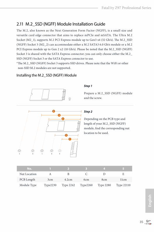
2.11 M.2_SSD (NGFF) Module Installation GuideThe M.2, also known as the Next Generation Form Factor (NGFF), is a small size and versatile card edge connector that aims to replace mPCIe and mSATA. The Ultra M.2 Socket (M2_1), supports M.2 PCI Express module up to Gen3 x4 (32 Gb/s). The M.2_SSD (NGFF) Socket 3 (M2_2) can accommodate either a M.2 SATA3 6.0 Gb/s module or a M.2 PCI Express module up to Gen 2 x2 (10 Gb/s). Please be noted that the M.2_SSD (NGFF) Socket 3 is shared with the SATA Express connector; you can only choose either the M.2_SSD (NGFF) Socket 3 or the SATA Express connector to use.*The M.2_SSD (NGFF) Socket 3 supports SSD drives. Please note that the WiFi or other non-SSD M.2 modules are not supported.
Installing the M.2_SSD (NGFF) Module
Step 1
Prepare a M.2_SSD (NGFF) module and the screw.
3
2
4
5
BCDE A
1
Step 2
Depending on the PCB type and length of your M.2_SSD (NGFF) module, find the corresponding nut location to be used.
No. 1 2 3 4 5
Nut Location A B C D E
PCB Length 3cm 4.2cm 6cm 8cm 11cm
Module Type Type2230 Type 2242 Type2260 Type 2280 Type 22110
36 37
English
Fatal1ty Z97 Professional Series
BCDE A
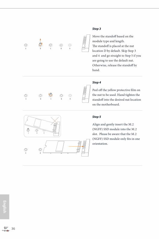
Step 3
Move the standoff based on the module type and length. The standoff is placed at the nut location D by default. Skip Step 3 and 4 and go straight to Step 5 if you are going to use the default nut. Otherwise, release the standoff by hand.
BCDE A
Step 4
Peel off the yellow protective film on the nut to be used. Hand tighten the standoff into the desired nut location on the motherboard.
BC A
ABCDE
Step 5
Align and gently insert the M.2 (NGFF) SSD module into the M.2 slot. Please be aware that the M.2 (NGFF) SSD module only fits in one orientation.
36 37
Engl
ish
Fatal1ty Z97 Professional Series
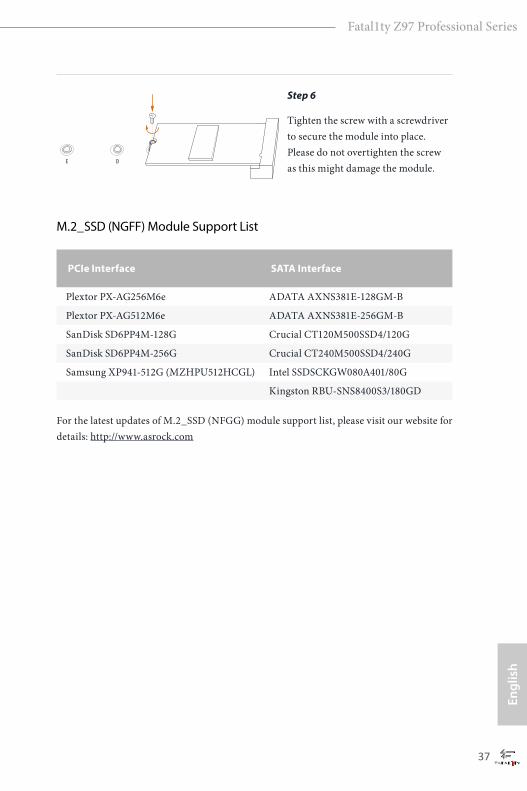
PCIe Interface SATA Interface
Plextor PX-AG256M6e ADATA AXNS381E-128GM-B
Plextor PX-AG512M6e ADATA AXNS381E-256GM-B
SanDisk SD6PP4M-128G Crucial CT120M500SSD4/120G
SanDisk SD6PP4M-256G Crucial CT240M500SSD4/240G
Samsung XP941-512G (MZHPU512HCGL) Intel SSDSCKGW080A401/80G
Kingston RBU-SNS8400S3/180GD
NUT1NUT2DE
Step 6
Tighten the screw with a screwdriver to secure the module into place. Please do not overtighten the screw as this might damage the module.
M.2_SSD (NGFF) Module Support List
For the latest updates of M.2_SSD (NFGG) module support list, please visit our website for details: http://www.asrock.com
38 39
English
Fatal1ty Z97 Professional Series
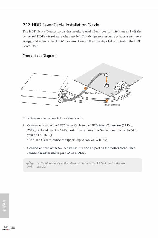
2.12 HDD Saver Cable Installation GuideThe HDD Saver Connector on this motherboard allows you to switch on and off the connected HDDs via software when needed. This design secures more privacy, saves more energy, and extends the HDDs' lifespans. Please follow the steps below to install the HDD Saver Cable.
Connection Diagram
*The diagram shown here is for reference only.
1. Connect one end of the HDD Saver Cable to the HDD Saver Connector (SATA_PWR_1) placed near the SATA ports. Then connect the SATA power connector(s) to your SATA HDD(s). * The HDD Saver Connector supports up to two SATA HDDs.
2. Connect one end of the SATA data cable to a SATA port on the motherboard. Then connect the other end to your SATA HDD(s).
2
1
HDD Saver Cable
SATA data cable
For the software configuration, please refer to the section 3.2 “F-Stream” in this user manual.
38 39
Engl
ish
Fatal1ty Z97 Professional Series
Chapter 3 Software and Utilities Operation 3.1 Installing DriversThe Support CD that comes with the motherboard contains necessary drivers and useful utilities that enhance the motherboard’s features.
Running The Support CDTo begin using the support CD, insert the CD into your CD-ROM drive. The CD automatically displays the Main Menu if “AUTORUN” is enabled in your computer. If the Main Menu does not appear automatically, locate and double click on the file “ASRSETUP.EXE” in the Support CD to display the menu.
Drivers MenuThe drivers compatible to your system will be auto-detected and listed on the support CD driver page. Please click Install All or follow the order from top to bottom to install those required drivers. Therefore, the drivers you install can work properly.
Utilities MenuThe Utilities Menu shows the application software that the motherboard supports. Click on a specific item then follow the installation wizard to install it.
To improve Windows 7 compatibility, please download and install the following hot fix provided by Microsoft. “KB2720599”: http://support.microsoft.com/kb/2720599/en-us
40 41
English
Fatal1ty Z97 Professional Series
3.2 F-StreamF-Stream is ASRock’s multi purpose software suite with a new interface, more new features and improved utilities, including XFast RAM, Dehumidifier, Good Night LED, FAN-Tastic Tuning, OC Tweaker and a whole lot more.
3.2.1 Installing F-StreamWhen you install the all-in-one driver to your system from ASRock’s support CD, F-Stream will be auto-installed as well. After the installation, you will find the icon “F-Stream“ on your desktop. Double-click the “F-Stream“ icon, F-Stream main menu will pop up.
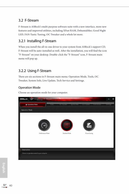
3.2.2 Using F-StreamThere are six sections in F-Stream main menu: Operation Mode, Tools, OC Tweaker, System Info, Live Update, Tech Service and Settings.
Operation ModeChoose an operation mode for your computer.
40 41
Engl
ish
Fatal1ty Z97 Professional Series
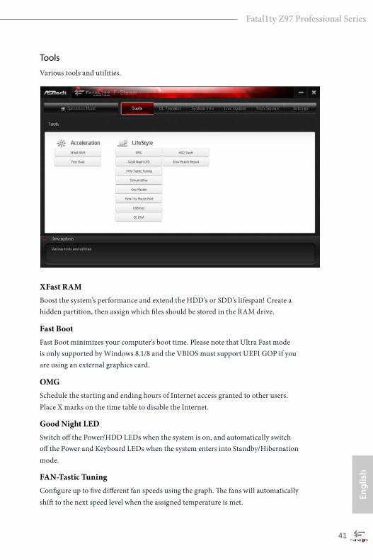
Tools
Various tools and utilities.
XFast RAMBoost the system’s performance and extend the HDD’s or SDD’s lifespan! Create a hidden partition, then assign which files should be stored in the RAM drive.
Fast BootFast Boot minimizes your computer's boot time. Please note that Ultra Fast mode is only supported by Windows 8.1/8 and the VBIOS must support UEFI GOP if you are using an external graphics card.
OMGSchedule the starting and ending hours of Internet access granted to other users. Place X marks on the time table to disable the Internet.
Good Night LEDSwitch off the Power/HDD LEDs when the system is on, and automatically switch off the Power and Keyboard LEDs when the system enters into Standby/Hibernation mode.
FAN-Tastic TuningConfigure up to five different fan speeds using the graph. The fans will automatically shift to the next speed level when the assigned temperature is met.

42 43
English
Fatal1ty Z97 Professional Series
DehumidifierPrevent motherboard damages due to dampness. Enable this function and configure the period of time until the computer powers on, and the duration of the dehumidifying process.
Key Master
Enhance your mouse and keyboard with customizable macros, sniper modes, scroll speed, key repeat rates and repeat delay.
Fata1ty Mouse Port
You are installing the mouse into Fata1ty Mouse Port. After applying your mouse polling rate, move your mouse to feel it!
USB Key
Plug in the USB Key and let your computer log in to windows automatically.
OC DNAOC DNA is an unique software which helps to save your OC settings as a profile. Then you can send this OC setting profile to the friends.
HDD SaverA quick-and-easy way to power up and down the drive on demand. Use a customized hotkey (Ctrl + Alt + S, by default) or simply slide to turn on and off up to two internal SATA HDDs connected to the power supply connector. Also a password can be set to change HDD power mode for more privacy and safety.
Disk Health ReportDisk Health Report is a hard disk health monitoring utility that displays detailed HDD information, such as hard disk model, serial number, firmware, power on count, power on hours, S.M.A.R.T. values, current temperature, etc. HDD, SSD and optical disk drives are all supported. The health status block displays Good (in green color), Caution (in yellow color) or Bad (in red color). Click on the health status icon to configure settings for an alert to be triggered.
42 43
Engl
ish
Fatal1ty Z97 Professional Series
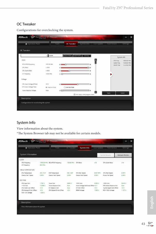
OC TweakerConfigurations for overclocking the system.
System InfoView information about the system. *The System Browser tab may not be available for certain models.
44 45
English
Fatal1ty Z97 Professional Series
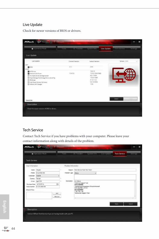
Live UpdateCheck for newer versions of BIOS or drivers.
Tech ServiceContact Tech Service if you have problems with your computer. Please leave your contact information along with details of the problem.
44 45
Engl
ish
Fatal1ty Z97 Professional Series
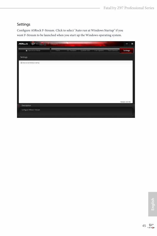
SettingsConfigure ASRock F-Stream. Click to select "Auto run at Windows Startup" if you want F-Stream to be launched when you start up the Windows operating system.
46 47
English
Fatal1ty Z97 Professional Series
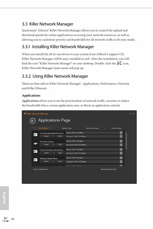
3.3 Killer Network ManagerQualcomm® Atheros® Killer Network Manager allows you to control the upload and download speeds for online applications accessing your network resources, as well as allowing you to customize priority and bandwidth for all network traffic to fit your needs.
3.3.1 Installing Killer Network ManagerWhen you install the all-in-one driver to your system from ASRock’s support CD, Killer Network Manager will be auto-installed as well. After the installation, you will find the icon “Killer Network Manager“ on your desktop. Double-click the icon, Killer Network Manager main menu will pop up.
3.3.2 Using Killer Network ManagerThere are four tabs in Killer Network Manager: Applications, Performance, Network and Killer Ethernet.
ApplicationsApplications allows you to set the prioritization of network traffic, increase or reduce the bandwidth that a certain application uses, or block an application entirely.

46 47
Engl
ish
Fatal1ty Z97 Professional Series
PerformancePerformance allows you to view in real time your system performance and current network utilization for download and upload traffic.
Network Network allows you to set your preferred upload/download speeds and test the network speed. * You must have Adobe Flash Player installed to run the network speed test.

48 PB
English
Fatal1ty Z97 Professional Series
Killer EthernetKiller Ethernet displays the network information.
PB 49
Engl
ish
Fatal1ty Z97 Professional Series
3.4 Intel® Rapid Start TechnologyIntel® Rapid Start Technology enables your system to wake up faster from deep sleep, saving time and power consumption. Feel secure to know that your system will resume to working condition even if an unexpected power loss happens while the PC is in sleep mode.
3.4.1 System Requirements
• Confirm whether your motherboard supports this feature.
• Operating system: Microsoft Windows 8.1/8/7 (32- or 64-bit edition)
• Set the SATA mode to AHCI. If Windows 8.1/8/7 is already installed under IDE mode, directly changing the SATA mode to AHCI may cause Windows 8.1/8/7 to crash while booting. If your system is not in AHCI mode, please follow the instructions below.
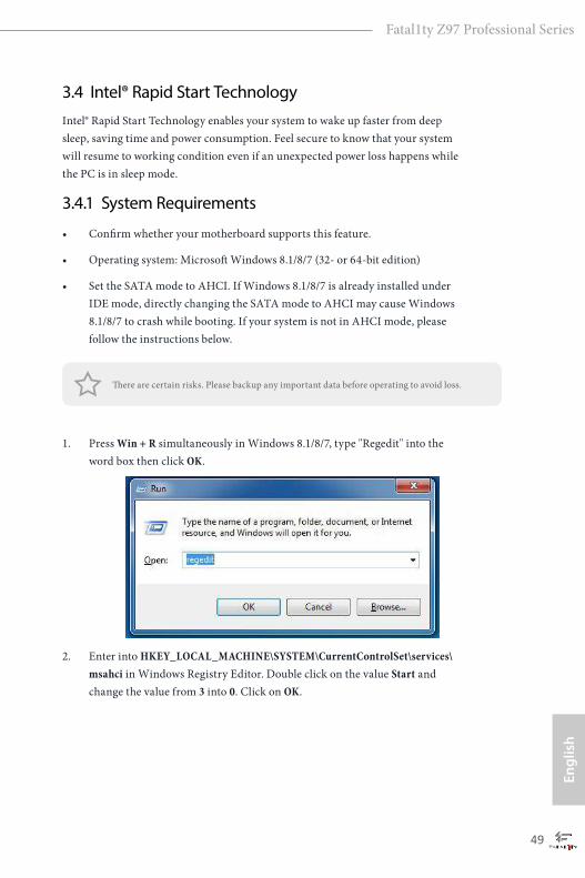
1. Press Win + R simultaneously in Windows 8.1/8/7, type "Regedit" into the word box then click OK.
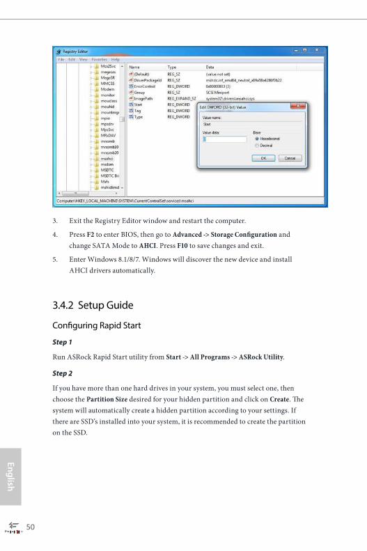
2. Enter into HKEY_LOCAL_MACHINE\SYSTEM\CurrentControlSet\services\msahci in Windows Registry Editor. Double click on the value Start and change the value from 3 into 0. Click on OK.
There are certain risks. Please backup any important data before operating to avoid loss.
50 51
English
Fatal1ty Z97 Professional Series
3. Exit the Registry Editor window and restart the computer.
4. Press F2 to enter BIOS, then go to Advanced ‐> Storage Configuration and change SATA Mode to AHCI. Press F10 to save changes and exit.
5. Enter Windows 8.1/8/7. Windows will discover the new device and install AHCI drivers automatically.
3.4.2 Setup Guide
Configuring Rapid Start
Step 1
Run ASRock Rapid Start utility from Start -> All Programs -> ASRock Utility.
Step 2
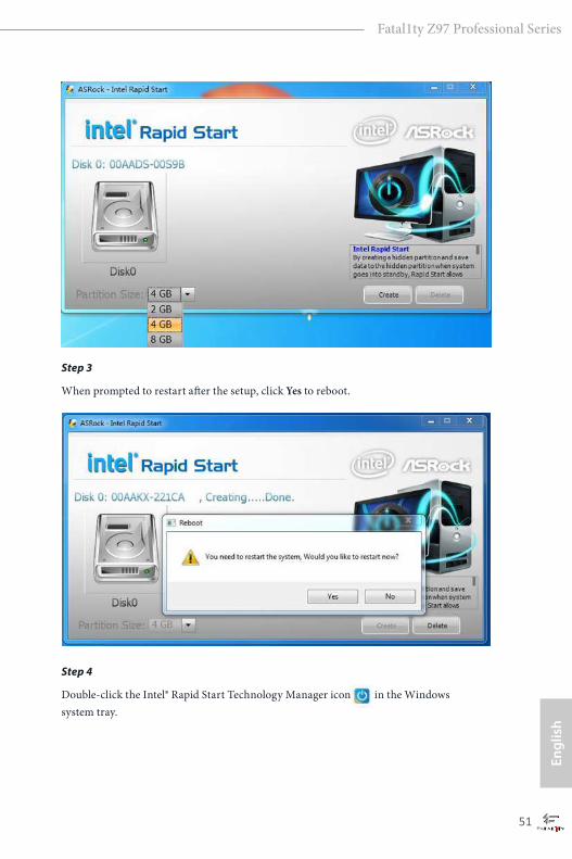
If you have more than one hard drives in your system, you must select one, then choose the Partition Size desired for your hidden partition and click on Create. The system will automatically create a hidden partition according to your settings. If there are SSD’s installed into your system, it is recommended to create the partition on the SSD.
50 51
Engl
ish
Fatal1ty Z97 Professional Series
Step 3
When prompted to restart after the setup, click Yes to reboot.
Step 4
Double-click the Intel® Rapid Start Technology Manager icon in the Windows system tray.
52 53
English
Fatal1ty Z97 Professional Series
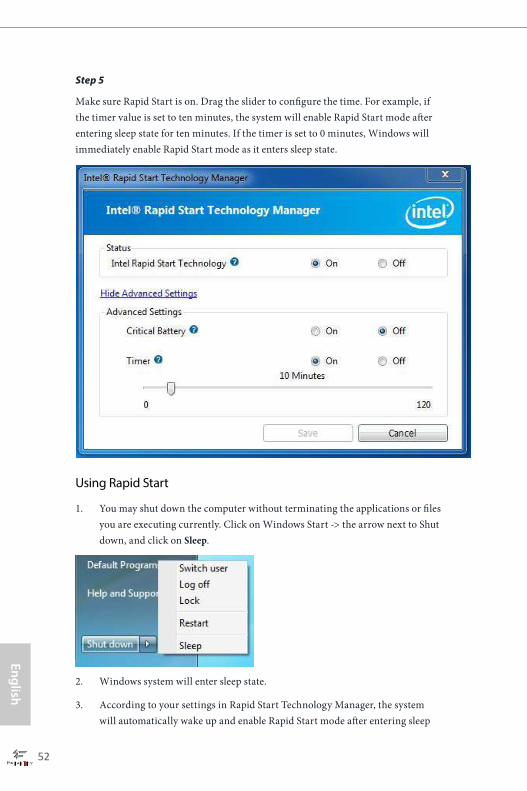
Step 5
Make sure Rapid Start is on. Drag the slider to configure the time. For example, if the timer value is set to ten minutes, the system will enable Rapid Start mode after entering sleep state for ten minutes. If the timer is set to 0 minutes, Windows will immediately enable Rapid Start mode as it enters sleep state.
Using Rapid Start
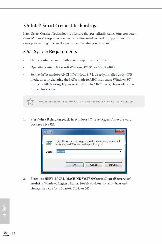
1. You may shut down the computer without terminating the applications or files you are executing currently. Click on Windows Start ‐> the arrow next to Shut down, and click on Sleep.
2. Windows system will enter sleep state.
3. According to your settings in Rapid Start Technology Manager, the system will automatically wake up and enable Rapid Start mode after entering sleep

52 53
Engl
ish
Fatal1ty Z97 Professional Series
state for a period of time. The power of the computer in Rapid Start mode can be cut off, it will not cause data loss of the programs or files you were executing before entering sleep state.
4. When you wish to continue to use the computer just hit the power button, the system will rapidly return to Windows, the programs and files which you were using before entering sleep state will be accessible immediately.
54 55
English
Fatal1ty Z97 Professional Series
3.5 Intel® Smart Connect TechnologyIntel® Smart Connect Technology is a feature that periodically wakes your computer from Windows® sleep state to refresh email or social networking applications. It saves your waiting time and keeps the content always up-to-date.
3.5.1 System Requirements
• Confirm whether your motherboard supports this feature.
• Operating system: Microsoft Windows 8/7 (32- or 64-bit edition)
• Set the SATA mode to AHCI. If Windows 8/7 is already installed under IDE mode, directly changing the SATA mode to AHCI may cause Windows 8/7 to crash while booting. If your system is not in AHCI mode, please follow the instructions below.
1. Press Win + R simultaneously in Windows 8/7, type "Regedit" into the word box then click OK.
2. Enter into HKEY_LOCAL_MACHINE\SYSTEM\CurrentControlSet\services\msahci in Windows Registry Editor. Double click on the value Start and change the value from 3 into 0. Click on OK.
There are certain risks. Please backup any important data before operating to avoid loss.
54 55
Engl
ish
Fatal1ty Z97 Professional Series
3.5.2 Setup Guide
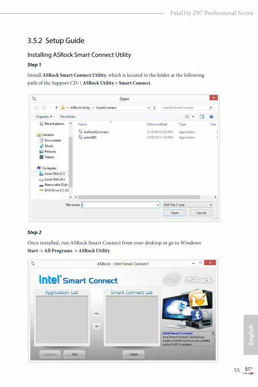
Installing ASRock Smart Connect UtilityStep 1
Install ASRock Smart Connect Utility, which is located in the folder at the following path of the Support CD: \ ASRock Utility > Smart Connect.
Step 2
Once installed, run ASRock Smart Connect from your desktop or go to Windows Start -> All Programs -> ASRock Utility.
56 57
English
Fatal1ty Z97 Professional Series
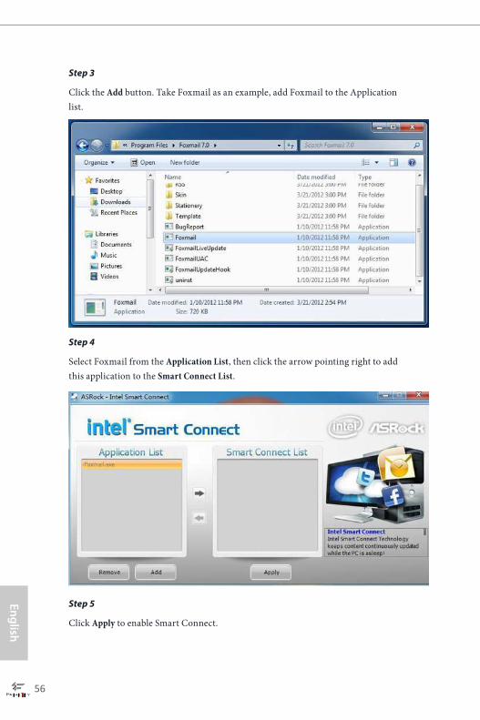
Step 3
Click the Add button. Take Foxmail as an example, add Foxmail to the Application list.
Step 4
Select Foxmail from the Application List, then click the arrow pointing right to add this application to the Smart Connect List.
Step 5
Click Apply to enable Smart Connect.

56 57
Engl
ish
Fatal1ty Z97 Professional Series
Step 6
Double-click the Intel® Smart Connect Technology Manager icon in the Windows system tray.
Step 7
Drag the slider to configure how often the system will connect to the network to download updates. Shorter durations will provide more frequent updates, but may cause more power consumption.
Using Smart Connect
1. Keep the applications which you wish to connect to the internet and receive updates while the system is in sleep state running. Foxmail for instance, keep Foxmail running.
2. Click on Windows Start -> the arrow next to Shut down, and click on Sleep.
3. Windows system will enter sleep state.

58 59
English
Fatal1ty Z97 Professional Series
4. The system will wake up from sleep state periodically, and then start to update Foxmail. The screen will not display anything so the computer can maintain minimum power usage. Afterwards, the system will automatically return to sleep state again.
5. Upon waking up the system, you will find the new mail that were sent to you during sleep state are already updated and ready to be read in Foxmail.

58 59
Engl
ish
Fatal1ty Z97 Professional Series
3.6 ASRock Cloud (Intel® I218V)
ASRock makes your mobile devices connect to your PC seamlessly!
Have you ever been in a situation where you emergently needed certain files in your computer, however the computer was gazillion miles away out of reach? ASRock Cloud includes several technologies and software solutions for remotely controlling your computer, even if the computer is in off mode. For ASRock motherboards with a Intel® LAN chip, ASRock Cloud allows users to remotely wake up their computers via the internet by using a secondary device, such as a smartphone or tablet. Users may use Orbweb.ME Professional to remotely wake up and control their computers, or they could wake up the computer then use any other preferred remote desktop application. This motherboard supports Remote Wake Technology with the onboard Intel® LAN, so you can connect with your PC from anywhere in the world. You will be able to power your PC on or turn it off, monitor and take control of it remotely with another smartphone, tablet or computer.*ASRock Cloud is supported on Windows 8.1.
60 61
English
Fatal1ty Z97 Professional Series
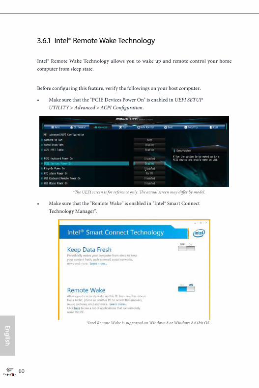
3.6.1 Intel® Remote Wake Technology
Intel® Remote Wake Technology allows you to wake up and remote control your home computer from sleep state.
Before configuring this feature, verify the followings on your host computer:
• Make sure that the "PCIE Devices Power On" is enabled in UEFI SETUP UTILITY > Advanced > ACPI Configuration.
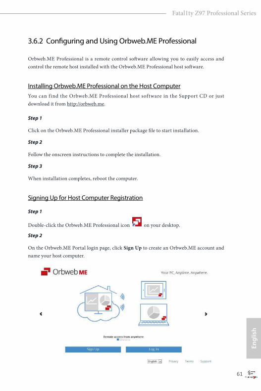
• Make sure that the "Remote Wake" is enabled in "Intel® Smart Connect Technology Manager".
*The UEFI screen is for reference only. The actual screen may differ by model.
*Intel Remote Wake is supported on Windows 8 or Windows 8 64bit OS.
60 61
Engl
ish
Fatal1ty Z97 Professional Series
3.6.2 Configuring and Using Orbweb.ME Professional
Orbweb.ME Professional is a remote control software allowing you to easily access and control the remote host installed with the Orbweb.ME Professional host software.
Installing Orbweb.ME Professional on the Host ComputerYou can find the Orbweb.ME Professional host software in the Support CD or just download it from http://orbweb.me.
Step 1
Click on the Orbweb.ME Professional installer package file to start installation.
Step 2
Follow the onscreen instructions to complete the installation.
Step 3
When installation completes, reboot the computer.
Signing Up for Host Computer Registration
Step 1
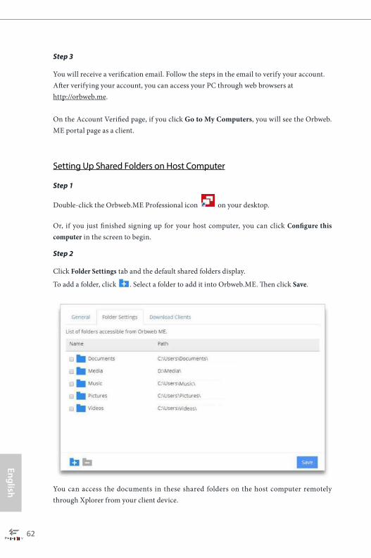
Double-click the Orbweb.ME Professional icon on your desktop.
Step 2
On the Orbweb.ME Portal login page, click Sign Up to create an Orbweb.ME account and name your host computer.
62 63
English
Fatal1ty Z97 Professional Series
Step 3
You will receive a verification email. Follow the steps in the email to verify your account.After verifying your account, you can access your PC through web browsers at http://orbweb.me.
On the Account Verified page, if you click Go to My Computers, you will see the Orbweb.ME portal page as a client.
Setting Up Shared Folders on Host Computer
Step 1
Double-click the Orbweb.ME Professional icon on your desktop.
Or, if you just finished signing up for your host computer, you can click Configure this computer in the screen to begin.
Step 2
Click Folder Settings tab and the default shared folders display.
To add a folder, click . Select a folder to add it into Orbweb.ME. Then click Save.
You can access the documents in these shared folders on the host computer remotely through Xplorer from your client device.
62 63
Engl
ish
Fatal1ty Z97 Professional Series
REMOTE ACCESS FROM A CLIENT DEVICE
Using Remote Wake-Up
Remote Wake-Up allows you to remotely put your host computer to sleep and wake your host computer up from a client device.
If you use a motherboard with dual LAN ports, please disable one of the LAN ports to use the Remote Wake-Up function. To do so, go to Control Panel > Network and Sharing Center > Manage Network Connections, right-click Local Area Connections and select Disable.
For Windows PC users:
Step 1
Go to Orbweb.ME portal login page: http://orbweb.me
Step 2
Log in with your Orbweb.ME account and password.
Step 3
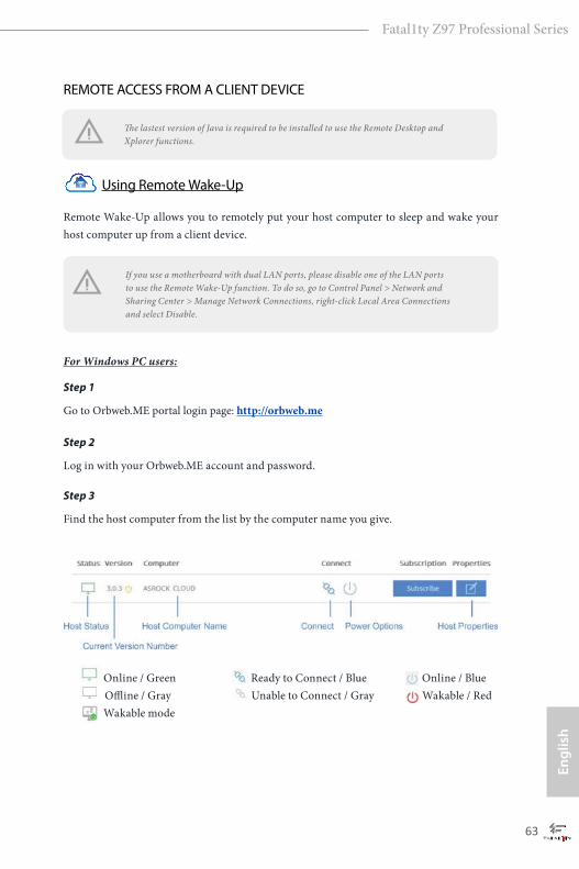
Find the host computer from the list by the computer name you give.
Online / Green Ready to Connect / Blue Online / Blue Offline / Gray Unable to Connect / Gray Wakable / Red Wakable mode
The lastest version of Java is required to be installed to use the Remote Desktop and Xplorer functions.
64 65
English
Fatal1ty Z97 Professional Series
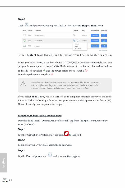
Step 4
Click and power options appear. Click to select Restart, Sleep or Shut Down.
S e l e c t R e s t a r t f r o m t h e o p t i o n s t o r e s t a r t y o u r h o s t c o m p u t e r r e m o t e l y.
When you select Sleep, if the host device is WOW(Wake-On-Wan) compatible, you can put your host computer to sleep (S3/S4). The host status in the Status column shows offline
and ready to be awaked and the power option shows wakable . To wake up the computer, click .
If you select Shut Down, you can turn off your computer remotely. However, the Intel® Remote Wake Technology does not support remote wake-up from shutdwon (S5). Please physically turn on your host computer.
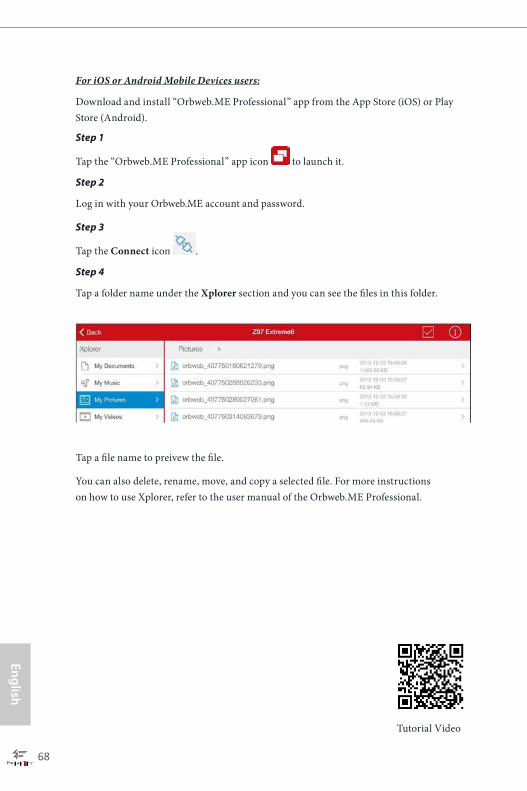
For iOS or Android Mobile Devices users:
Download and install “Orbweb.ME Professional” app from the App Store (iOS) or Play Store (Android).
Step 1
Tap the “Orbweb.ME Professional” app icon to launch it.
Step 2
Log in with your Orbweb.ME account and password.
Step 3
Tap the Power Options icon and power options appear.
Please be noted that if the host device is not WOW compatible, the host status icon will turn offline and the power option icon will disappear. You have to physically wake up computer in order to bring power option icon back to online.
64 65
Engl
ish
Fatal1ty Z97 Professional Series
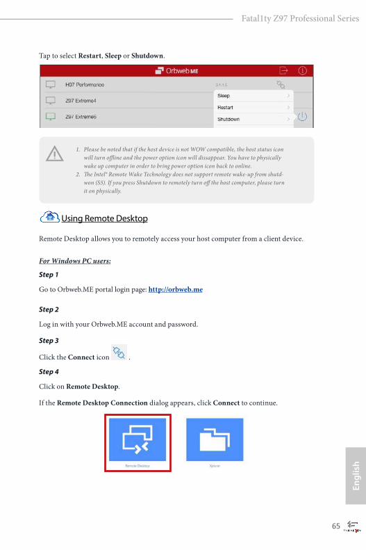
Tap to select Restart, Sleep or Shutdown.
Using Remote Desktop
Remote Desktop allows you to remotely access your host computer from a client device. For Windows PC users:
Step 1
Go to Orbweb.ME portal login page: http://orbweb.me
Step 2
Log in with your Orbweb.ME account and password.
Step 3
Click the Connect icon .
Step 4
Click on Remote Desktop.
If the Remote Desktop Connection dialog appears, click Connect to continue.
1. Please be noted that if the host device is not WOW compatible, the host status icon will turn offline and the power option icon will dissappear. You have to physically wake up computer in order to bring power option icon back to online.
2. The Intel® Remote Wake Technology does not support remote wake-up from shutd-won (S5). If you press Shutdown to remotely turn off the host computer, please turn it on physically.
66 67
English
Fatal1ty Z97 Professional Series
Step 5
Enter the Windows password to log in and you will see the desktop of your host computer.
For iOS or Android Mobile Devices users:
Download and install “Orbweb.ME Professional” app from the App Store (iOS) or Play Store (Android).
Step 1
Tap the “Orbweb.ME Professional” app icon to launch it.
Step 2
Log in with your Orbweb.ME account and password.
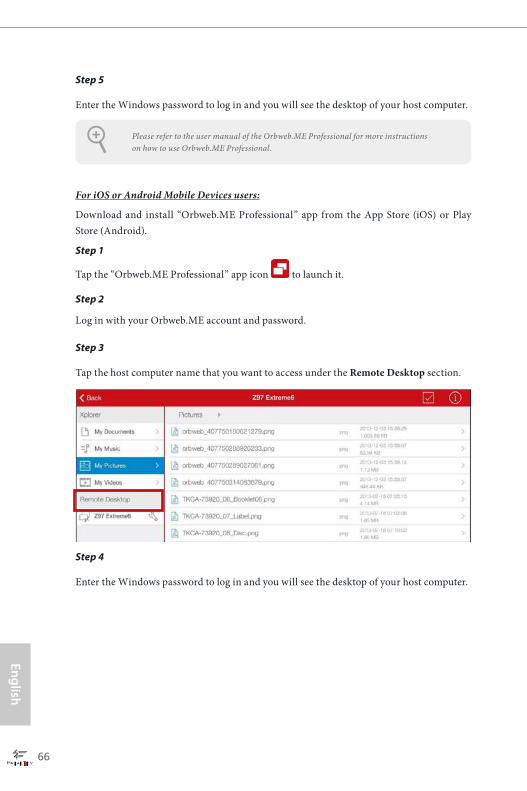
Step 3
Tap the host computer name that you want to access under the Remote Desktop section.
Step 4
Enter the Windows password to log in and you will see the desktop of your host computer.
Please refer to the user manual of the Orbweb.ME Professional for more instructions on how to use Orbweb.ME Professional.
66 67
Engl
ish
Fatal1ty Z97 Professional Series
Using Xplorer
Xplorer allows you to remotely access documents on your host computer from a client device. For Windows PC users:
Step 1
Go to Orbweb.ME portal login page: http://orbweb.me
Step 2
Log in with your Orbweb.ME account and password.
Step 3
Click the Connect icon .
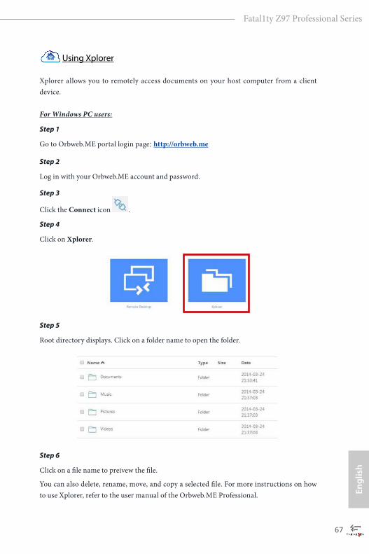
Step 4
Click on Xplorer.
Step 5
Root directory displays. Click on a folder name to open the folder.
Step 6
Click on a file name to preivew the file.
You can also delete, rename, move, and copy a selected file. For more instructions on how to use Xplorer, refer to the user manual of the Orbweb.ME Professional.
68 69
English
Fatal1ty Z97 Professional Series
Tutorial Video
For iOS or Android Mobile Devices users:
Download and install “Orbweb.ME Professional” app from the App Store (iOS) or Play Store (Android).
Step 1
Tap the “Orbweb.ME Professional” app icon to launch it.
Step 2
Log in with your Orbweb.ME account and password.
Step 3
Tap the Connect icon .
Step 4
Tap a folder name under the Xplorer section and you can see the files in this folder.
Tap a file name to preivew the file.
You can also delete, rename, move, and copy a selected file. For more instructions on how to use Xplorer, refer to the user manual of the Orbweb.ME Professional.

68 69
Engl
ish
Fatal1ty Z97 Professional Series
3.7 ASRock Cloud (Qualcomm® Atheros® KillerTM E2200 Series)
ASRock makes your mobile devices connect to your PC seamlessly!
Have you ever been in a situation where you emergently needed certain files in your computer, however the computer was gazi l l ion miles away out of reach? ASRock Cloud includes several technologies and software solutions for remotely controlling your computer, even if the computer is in off mode. For ASRock motherboards with a Qualcomm® Atheros® LAN chip, ASRock Cloud allows users to remotely wake up their computers via the internet by using a secondary device, such as a smartphone or tablet. Users may use Orbweb.ME Professional to remotely wake up and control their computers, or they could wake up the computer then use any other preferred remote desktop application. This motherboard supports Security Wake On Internet Technology with the onboard Qualcomm® Atheros® LAN, so you can connect with your PC from anywhere in the world. You will be able to power your PC on or turn it off, monitor and take control of it remotely with another smartphone, tablet or computer.*ASRock Cloud is supported on Windows 8.1 or Windows 7.
70 71
English
Fatal1ty Z97 Professional Series
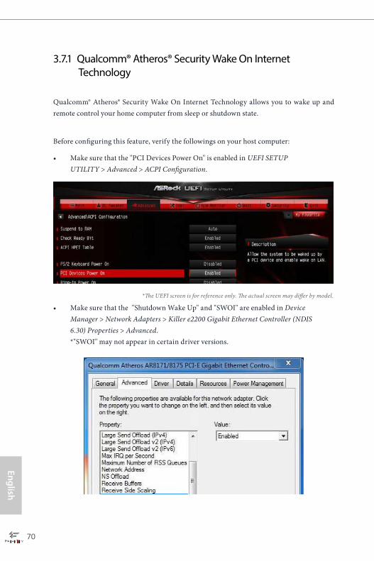
3.7.1 Qualcomm® Atheros® Security Wake On Internet Technology
Qualcomm® Atheros® Security Wake On Internet Technology allows you to wake up and remote control your home computer from sleep or shutdown state.
Before configuring this feature, verify the followings on your host computer:
• Make sure that the "PCI Devices Power On" is enabled in UEFI SETUP UTILITY > Advanced > ACPI Configuration.
• Make sure that the "Shutdown Wake Up" and "SWOI" are enabled in Device Manager > Network Adapters > Killer e2200 Gigabit Ethernet Controller (NDIS 6.30) Properties > Advanced. *"SWOI" may not appear in certain driver versions.
*The UEFI screen is for reference only. The actual screen may differ by model.
70 71
Engl
ish
Fatal1ty Z97 Professional Series
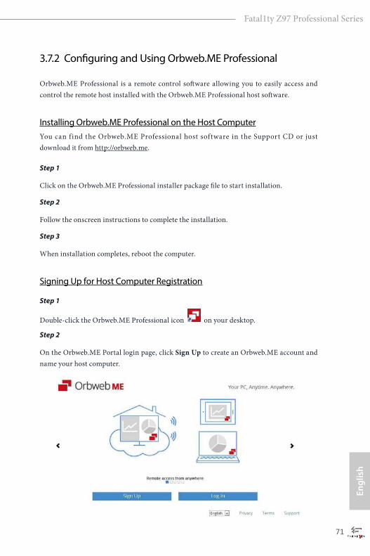
3.7.2 Configuring and Using Orbweb.ME Professional
Orbweb.ME Professional is a remote control software allowing you to easily access and control the remote host installed with the Orbweb.ME Professional host software.
Installing Orbweb.ME Professional on the Host ComputerYou can find the Orbweb.ME Professional host software in the Support CD or just download it from http://orbweb.me.
Step 1
Click on the Orbweb.ME Professional installer package file to start installation.
Step 2
Follow the onscreen instructions to complete the installation.
Step 3
When installation completes, reboot the computer.
Signing Up for Host Computer Registration
Step 1
Double-click the Orbweb.ME Professional icon on your desktop.
Step 2
On the Orbweb.ME Portal login page, click Sign Up to create an Orbweb.ME account and name your host computer.

72 73
English
Fatal1ty Z97 Professional Series
Step 3
You will receive a verification email. Follow the steps in the email to verify your account.After verifying your account, you can access your PC through web browsers at http://orbweb.me.
On the Account Verified page, if you click Go to My Computers, you will see the Orbweb.ME portal page as a client.
Setting Up Shared Folders on Host Computer
Step 1
Double-click the Orbweb.ME Professional icon on your desktop.
Or, if you just finished signing up for your host computer, you can click Configure this computer in the screen to begin.
Step 2
Click Folder Settings tab and the default shared folders display.
To add a folder, click . Select a folder to add it into Orbweb.ME. Then click Save.
You can access the documents in these shared folders on the host computer remotely through Xplorer from your client device.
72 73
Engl
ish
Fatal1ty Z97 Professional Series
The lastest version of Java is required to be installed to use the Remote Desktop and Xplorer functions.
REMOTE ACCESS FROM A CLIENT DEVICE
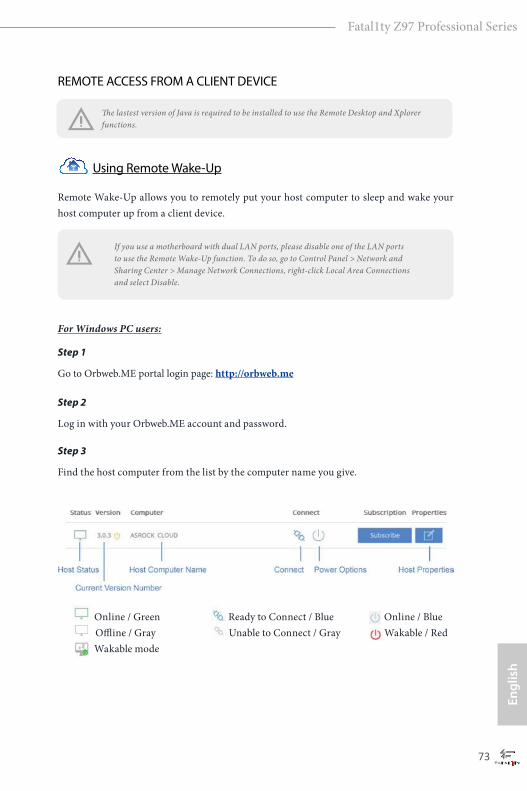
Using Remote Wake-Up
Remote Wake-Up allows you to remotely put your host computer to sleep and wake your host computer up from a client device.
If you use a motherboard with dual LAN ports, please disable one of the LAN ports to use the Remote Wake-Up function. To do so, go to Control Panel > Network and Sharing Center > Manage Network Connections, right-click Local Area Connections and select Disable.
For Windows PC users:
Step 1
Go to Orbweb.ME portal login page: http://orbweb.me
Step 2
Log in with your Orbweb.ME account and password.
Step 3
Find the host computer from the list by the computer name you give.
Online / Green Ready to Connect / Blue Online / Blue Offline / Gray Unable to Connect / Gray Wakable / Red Wakable mode
74 75
English
Fatal1ty Z97 Professional Series
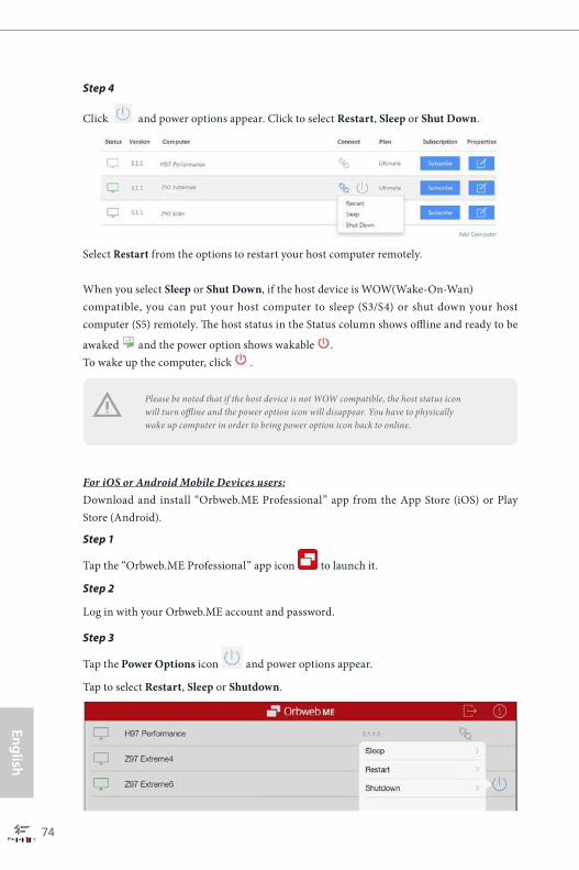
Step 4
Click and power options appear. Click to select Restart, Sleep or Shut Down.
Select Restart from the options to restart your host computer remotely.
When you select Sleep or Shut Down, if the host device is WOW(Wake-On-Wan)compatible, you can put your host computer to sleep (S3/S4) or shut down your host computer (S5) remotely. The host status in the Status column shows offline and ready to be
awaked and the power option shows wakable . To wake up the computer, click .
For iOS or Android Mobile Devices users:Download and install “Orbweb.ME Professional” app from the App Store (iOS) or Play Store (Android).
Step 1
Tap the “Orbweb.ME Professional” app icon to launch it.
Step 2
Log in with your Orbweb.ME account and password.
Step 3
Tap the Power Options icon and power options appear.
Tap to select Restart, Sleep or Shutdown.
Please be noted that if the host device is not WOW compatible, the host status icon will turn offline and the power option icon will disappear. You have to physically wake up computer in order to bring power option icon back to online.
74 75
Engl
ish
Fatal1ty Z97 Professional Series
Using Remote Desktop
Remote Desktop allows you to remotely access your host computer from a client device. For Windows PC users:
Step 1
Go to Orbweb.ME portal login page: http://orbweb.me
Step 2
Log in with your Orbweb.ME account and password.
Step 3
Click the Connect icon .
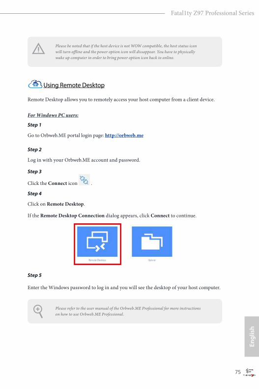
Step 4
Click on Remote Desktop.
If the Remote Desktop Connection dialog appears, click Connect to continue.
Step 5
Enter the Windows password to log in and you will see the desktop of your host computer.
Please refer to the user manual of the Orbweb.ME Professional for more instructions on how to use Orbweb.ME Professional.
Please be noted that if the host device is not WOW compatible, the host status icon will turn offline and the power option icon will dissappear. You have to physically wake up computer in order to bring power option icon back to online.
76 77
English
Fatal1ty Z97 Professional Series
For iOS or Android Mobile Devices users:
Download and install “Orbweb.ME Professional” app from the App Store (iOS) or Play Store (Android).
Step 1
Tap the “Orbweb.ME Professional” app icon to launch it.
Step 2
Log in with your Orbweb.ME account and password.
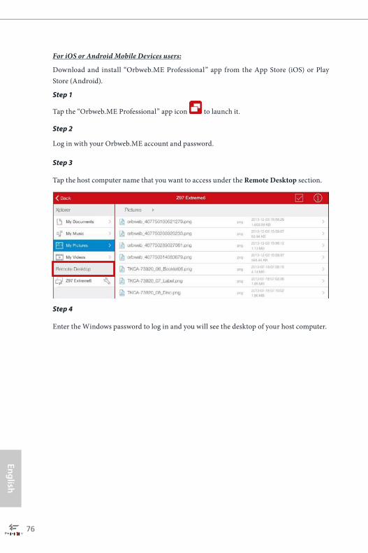
Step 3
Tap the host computer name that you want to access under the Remote Desktop section.
Step 4
Enter the Windows password to log in and you will see the desktop of your host computer.
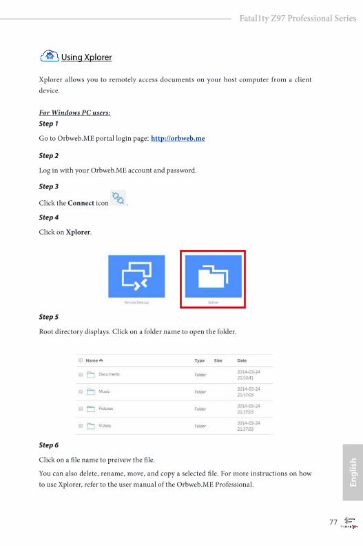
76 77
Engl
ish
Fatal1ty Z97 Professional Series
Using Xplorer
Xplorer allows you to remotely access documents on your host computer from a client device. For Windows PC users:Step 1
Go to Orbweb.ME portal login page: http://orbweb.me
Step 2
Log in with your Orbweb.ME account and password.
Step 3
Click the Connect icon .
Step 4
Click on Xplorer.
Step 5
Root directory displays. Click on a folder name to open the folder.
Step 6
Click on a file name to preivew the file.
You can also delete, rename, move, and copy a selected file. For more instructions on how to use Xplorer, refer to the user manual of the Orbweb.ME Professional.
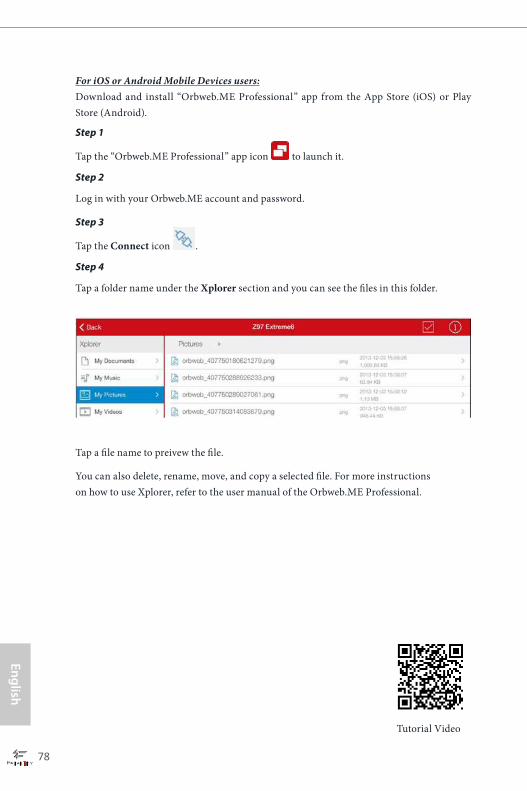
78 79
English
Fatal1ty Z97 Professional Series
Tutorial Video
For iOS or Android Mobile Devices users:Download and install “Orbweb.ME Professional” app from the App Store (iOS) or Play Store (Android).
Step 1
Tap the “Orbweb.ME Professional” app icon to launch it.
Step 2
Log in with your Orbweb.ME account and password.
Step 3
Tap the Connect icon .
Step 4
Tap a folder name under the Xplorer section and you can see the files in this folder.
Tap a file name to preivew the file.
You can also delete, rename, move, and copy a selected file. For more instructions on how to use Xplorer, refer to the user manual of the Orbweb.ME Professional.
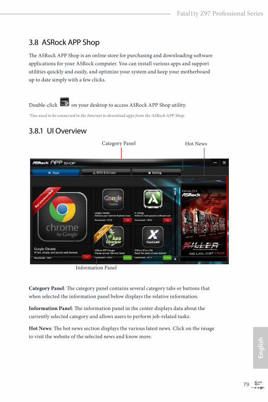
78 79
Engl
ish
Fatal1ty Z97 Professional Series
3.8 ASRock APP ShopThe ASRock APP Shop is an online store for purchasing and downloading software applications for your ASRock computer. You can install various apps and support utilities quickly and easily, and optimize your system and keep your motherboard up to date simply with a few clicks.
Double-click on your desktop to access ASRock APP Shop utility.
*You need to be connected to the Internet to download apps from the ASRock APP Shop.
3.8.1 UI Overview
Category Panel: The category panel contains several category tabs or buttons that when selected the information panel below displays the relative information.
Information Panel: The information panel in the center displays data about the currently selected category and allows users to perform job-related tasks.
Hot News: The hot news section displays the various latest news. Click on the image to visit the website of the selected news and know more.
Information Panel
Hot NewsCategory Panel
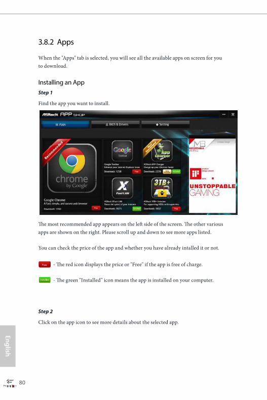
80 81
English
Fatal1ty Z97 Professional Series
3.8.2 Apps
When the "Apps" tab is selected, you will see all the available apps on screen for you to download.
Installing an AppStep 1
Find the app you want to install.
The most recommended app appears on the left side of the screen. The other various apps are shown on the right. Please scroll up and down to see more apps listed.
You can check the price of the app and whether you have already intalled it or not.
- The red icon displays the price or "Free" if the app is free of charge.
- The green "Installed" icon means the app is installed on your computer.
Step 2
Click on the app icon to see more details about the selected app.
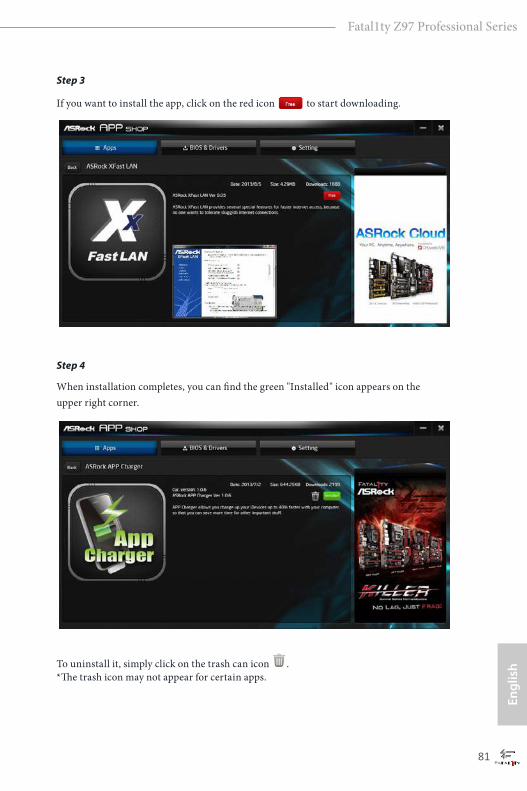
80 81
Engl
ish
Fatal1ty Z97 Professional Series
Step 3
If you want to install the app, click on the red icon to start downloading.
Step 4
When installation completes, you can find the green "Installed" icon appears on the upper right corner.
To uninstall it, simply click on the trash can icon . *The trash icon may not appear for certain apps.

82 83
English
Fatal1ty Z97 Professional Series
Upgrading an AppYou can only upgrade the apps you have already installed. When there is an available new version for your app, you will find the mark of "New Version" appears below the installed app icon.
Step 1
Click on the app icon to see more details.
Step 2
Click on the yellow icon to start upgrading.

82 83
Engl
ish
Fatal1ty Z97 Professional Series
3.8.3 BIOS & Drivers
Installing BIOS or Drivers
When the "BIOS & Drivers" tab is selected, you will see a list of recommended or critical updates for the BIOS or drivers. Please update them all soon.
Step 1
Please check the item information before update. Click on to see more details.
Step 2
Click to select one or more items you want to update.
Step 3
Click Update to start the update process.
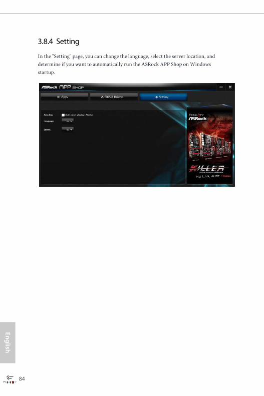
84 85
English
Fatal1ty Z97 Professional Series
3.8.4 Setting
In the "Setting" page, you can change the language, select the server location, and determine if you want to automatically run the ASRock APP Shop on Windows startup.
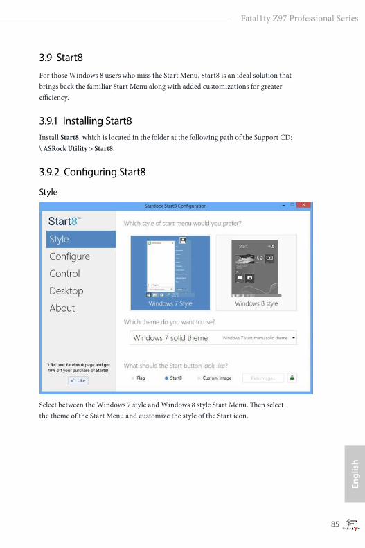
84 85
Engl
ish
Fatal1ty Z97 Professional Series
3.9 Start8For those Windows 8 users who miss the Start Menu, Start8 is an ideal solution that brings back the familiar Start Menu along with added customizations for greater efficiency.
3.9.1 Installing Start8Install Start8, which is located in the folder at the following path of the Support CD: \ ASRock Utility > Start8.
3.9.2 Configuring Start8
Style
Select between the Windows 7 style and Windows 8 style Start Menu. Then select the theme of the Start Menu and customize the style of the Start icon.
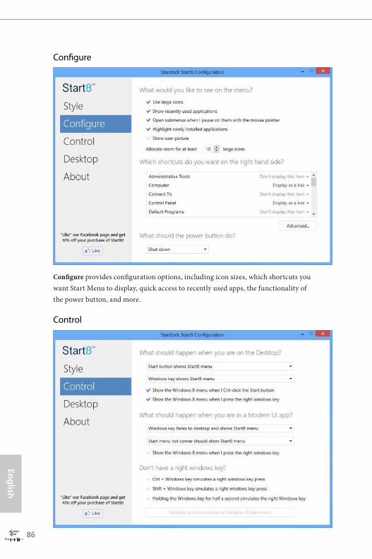
86 87
English
Fatal1ty Z97 Professional Series
Configure
Configure provides configuration options, including icon sizes, which shortcuts you want Start Menu to display, quick access to recently used apps, the functionality of the power button, and more.
Control
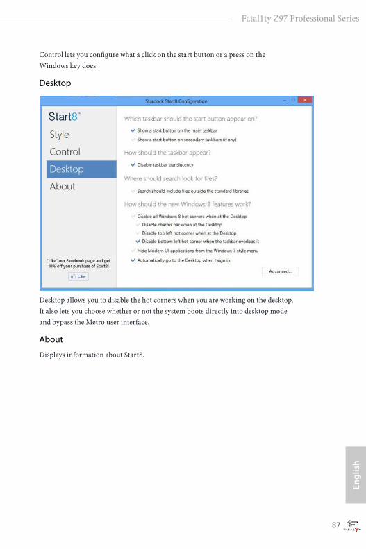
86 87
Engl
ish
Fatal1ty Z97 Professional Series
Control lets you configure what a click on the start button or a press on the Windows key does.
Desktop
Desktop allows you to disable the hot corners when you are working on the desktop. It also lets you choose whether or not the system boots directly into desktop mode and bypass the Metro user interface.
About
Displays information about Start8.

88 89
English
Fatal1ty Z97 Professional Series
3.10 SBX Pro Studio Technology
SBX Pro Studio
Click the power button on the left to activate or deactivate.
Surround
Control the level of audio immersion in music, movies and games.
CrystalizerEnhance music and movies to make them sound livelier.
BassControl the desired level of bass.
Crossover FrequencyRedirect all frequencies below this value to the optimal speaker for better bass response.
Smart VolumeAdjust the loudness of your audio playback automatically to minimize sudden volume changes.

88 89
Engl
ish
Fatal1ty Z97 Professional Series
Dialog PlusEnhance the voices in movies for clearer dialog.
CRYSTALVOICE
Select a recording device
Mic VolumeControl the level of mic volume.
Mic BoostControl the level of mic boost.
CrystalVoiceClick the power button on the left to activate or deactivate.
FXMorph your voice into different characters and accents.
Smart VolumeBe heard clearly without having to shout or whisper.
Noise ReductionEliminate unwanted background noise in your conversation.
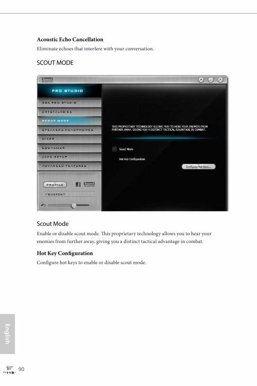
90 91
English
Fatal1ty Z97 Professional Series
Acoustic Echo CancellationEliminate echoes that interfere with your conversation.
SCOUT MODE
Scout ModeEnable or disable scout mode. This proprietary technology allows you to hear your enemies from further away, giving you a distinct tactical advantage in combat.
Hot Key ConfigurationConfigure hot keys to enable or disable scout mode.
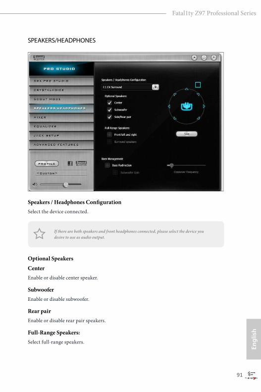
90 91
Engl
ish
Fatal1ty Z97 Professional Series
SPEAKERS/HEADPHONES
Speakers / Headphones ConfigurationSelect the device connected.
Optional Speakers
CenterEnable or disable center speaker.
SubwooferEnable or disable subwoofer.
Rear pairEnable or disable rear pair speakers.
Full-Range Speakers:Select full-range speakers.
If there are both speakers and front headphones connected, please select the device you desire to use as audio output.

92 93
English
Fatal1ty Z97 Professional Series
Bass Management
Bass RedirectionEnable or disable bass redirection.
Subwoofer GainEnable or disable subwoofer gain.
Crossover FrequencyRedirect all frequencies below this value to the optimal speaker for better bass response.
MIXER
PlaybackSpeakers
Control the level of speakers playback.
SPDIF-OutControl the level of SPDIF-Out playback.
BalanceControl the level of various speaker’s balance.
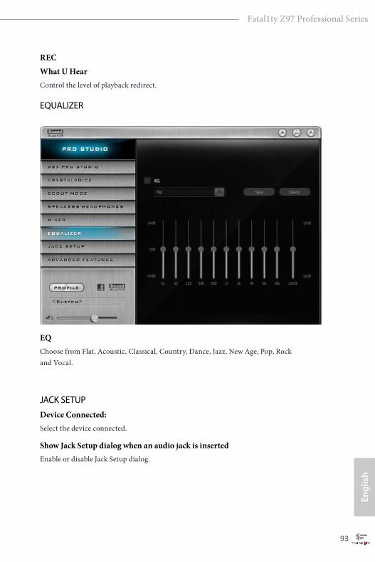
92 93
Engl
ish
Fatal1ty Z97 Professional Series
REC
What U HearControl the level of playback redirect.
EQUALIZER
EQChoose from Flat, Acoustic, Classical, Country, Dance, Jazz, New Age, Pop, Rock and Vocal.
JACK SETUP
Device Connected:Select the device connected.
Show Jack Setup dialog when an audio jack is insertedEnable or disable Jack Setup dialog.
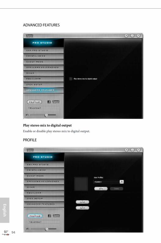
94 95
English
Fatal1ty Z97 Professional Series
ADVANCED FEATURES
Play stereo mix to digital outputEnable or disable play stereo mix to digital output.
PROFILE
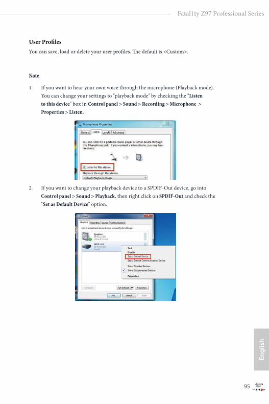
94 95
Engl
ish
Fatal1ty Z97 Professional Series
User ProfilesYou can save, load or delete your user profiles. The default is <Custom>.
Note
1. If you want to hear your own voice through the microphone (Playback mode). You can change your settings to "playback mode" by checking the "Listen to this device" box in Control panel > Sound > Recording > Microphone > Properties > Listen.
2. If you want to change your playback device to a SPDIF-Out device, go into Control panel > Sound > Playback, then right click on SPDIF-Out and check the "Set as Default Device" option.
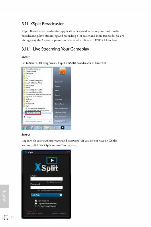
96 97
English
Fatal1ty Z97 Professional Series
3.11 XSplit Broadcaster XSplit Broadcaster is a desktop application designed to make your multimedia broadcasting, live-streaming and recording a lot easier and more fun to do, we are giving away the 3 months premium license which is worth US$24.95 for free!
3.11.1 Live Streaming Your Gameplay
Step 1
Go to Start > All Programs > XSplit > XSplit Broadcaster to launch it.
Step 2
Log in with your own username and password. (If you do not have an XSplit account, click No XSplit account? to register.)
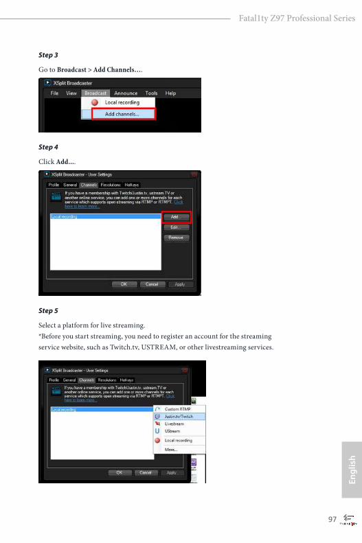
96 97
Engl
ish
Fatal1ty Z97 Professional Series
Step 3
Go to Broadcast > Add Channels….
Step 4
Click Add....
Step 5
Select a platform for live streaming. *Before you start streaming, you need to register an account for the streaming service website, such as Twitch.tv, USTREAM, or other livestreaming services.
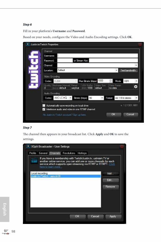
98 99
English
Fatal1ty Z97 Professional Series
Step 6
Fill in your platform's Username and Password.
Based on your needs, configure the Video and Audio Encoding settings. Click OK.
Step 7
The channel then appears in your broadcast list. Click Apply and OK to save the settings.
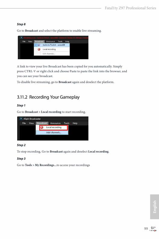
98 99
Engl
ish
Fatal1ty Z97 Professional Series
Step 8
Go to Broadcast and select the platform to enable live streaming.
A link to view your live Broadcast has been copied for you automatically. Simply press CTRL-V or right click and choose Paste to paste the link into the browser, and you can see your broadcast.
To disable live streaming, go to Broadcast again and deselect the platform.
3.11.2 Recording Your Gameplay
Step 1
Go to Broadcast > Local recording to start recording.
Step 2
To stop recording, Go to Broadcast again and deselect Local recording.
Step 3
Go to Tools > My Recordings...to access your recordings

100 101
English
Fatal1ty Z97 Professional Series
Chapter 4 UEFI SETUP UTILITY
4.1 IntroductionThis section explains how to use the UEFI SETUP UTILITY to configure your system. You may run the UEFI SETUP UTILITY by pressing <F2> or <Del> right after you power on the computer, otherwise, the Power-On-Self-Test (POST) will continue with its test routines. If you wish to enter the UEFI SETUP UTILITY after POST, restart the system by pressing <Ctl> + <Alt> + <Delete>, or by pressing the reset button on the system chassis. You may also restart by turning the system off and then back on.
4.1.1 UEFI Menu Bar
The top of the screen has a menu bar with the following selections:
Main For setting system time/date information
OC Tweaker For overclocking configurations
Advanced For advanced system configurations
Tool Useful tools
H/W Monitor Displays current hardware status
Boot For configuring boot settings and boot priority
Security For security settings
Exit Exit the current screen or the UEFI Setup Utility
Because the UEFI software is constantly being updated, the following UEFI setup screens and descriptions are for reference purpose only, and they may not exactly match what you see on your screen.
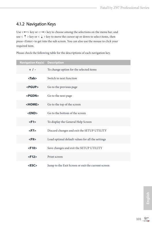
100 101
Engl
ish
Fatal1ty Z97 Professional Series
4.1.2 Navigation Keys
Use < > key or < > key to choose among the selections on the menu bar, and use < > key or < > key to move the cursor up or down to select items, then press <Enter> to get into the sub screen. You can also use the mouse to click your required item.
Please check the following table for the descriptions of each navigation key.
Navigation Key(s) Description
+ / - To change option for the selected items
<Tab> Switch to next function
<PGUP> Go to the previous page
<PGDN> Go to the next page
<HOME> Go to the top of the screen
<END> Go to the bottom of the screen
<F1> To display the General Help Screen
<F7> Discard changes and exit the SETUP UTILITY
<F9> Load optimal default values for all the settings
<F10> Save changes and exit the SETUP UTILITY
<F12> Print screen
<ESC> Jump to the Exit Screen or exit the current screen
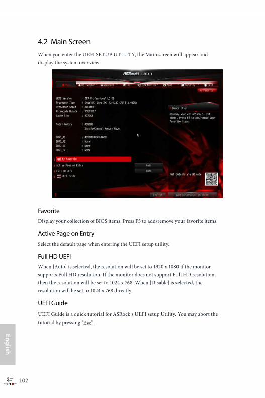
102 103
English
Fatal1ty Z97 Professional Series
4.2 Main ScreenWhen you enter the UEFI SETUP UTILITY, the Main screen will appear and display the system overview.
FavoriteDisplay your collection of BIOS items. Press F5 to add/remove your favorite items.
Active Page on EntrySelect the default page when entering the UEFI setup utility.
Full HD UEFIWhen [Auto] is selected, the resolution will be set to 1920 x 1080 if the monitor supports Full HD resolution. If the monitor does not support Full HD resolution, then the resolution will be set to 1024 x 768. When [Disable] is selected, the resolution will be set to 1024 x 768 directly.
UEFI Guide
UEFI Guide is a quick tutorial for ASRock's UEFI setup Utility. You may abort the tutorial by pressing "Esc".
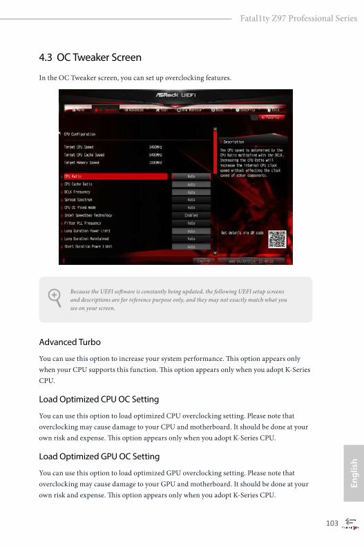
102 103
Engl
ish
Fatal1ty Z97 Professional Series
4.3 OC Tweaker Screen
In the OC Tweaker screen, you can set up overclocking features.
Advanced Turbo
You can use this option to increase your system performance. This option appears only when your CPU supports this function. This option appears only when you adopt K-Series CPU.
Load Optimized CPU OC Setting
You can use this option to load optimized CPU overclocking setting. Please note that overclocking may cause damage to your CPU and motherboard. It should be done at your own risk and expense. This option appears only when you adopt K-Series CPU.
Load Optimized GPU OC Setting
You can use this option to load optimized GPU overclocking setting. Please note that overclocking may cause damage to your GPU and motherboard. It should be done at your own risk and expense. This option appears only when you adopt K-Series CPU.
Because the UEFI software is constantly being updated, the following UEFI setup screens and descriptions are for reference purpose only, and they may not exactly match what you see on your screen.
104 105
English
Fatal1ty Z97 Professional Series
CPU Configuration
CPU RatioThe CPU speed is determined by the CPU Ratio multiplied with the BCLK. Increasing the CPU Ratio will increase the internal CPU clock speed without affecting the clock speed of other components.
CPU Cache RatioThe CPU Internal Bus Speed Ratio. The maximum should be the same as the CPU Ratio.
BCLK/PCIE FrequencyThe CPU speed is determined by the CPU Ratio multiplied with the BCLK. Increasing the BCLK will increase the internal CPU clock speed but also affect the clock speed of other components.
Spread SpectrumEnable Spread Spectrum to reduce electromagnetic interference for passing EMI tests. Disable to achieve higher clock speeds when overclocking.
CPU OC Fixed ModeCPU OC fix mode allows you to keep the max CPU ratio as your setting without throttling. Please note that overclocking may cause damage to your CPU and motherboard. It should be done at your own risk and expense.
Intel SpeedStep TechnologyIntel SpeedStep technology allows processors to switch between multiple frequen-cies and voltage points for better power saving and heat dissipation.
Intel Turbo Boost Technology (For K series CPU)
Intel Turbo Boost Technology enables the processor to run above its base operating frequency when the operating system requests the highest performance state.
Filter PLL FrequencyCPU BCLK Filter Frequency. Choose 1.6 for better overclocking capabilities.
Long Duration Power LimitConfigure Package Power Limit 1 in watts. When the limit is exceeded, the CPU ratio will be lowered after a period of time. A lower limit can protect the CPU and
104 105
Engl
ish
Fatal1ty Z97 Professional Series
save power, while a higher limit may improve performance.
Long Duration MaintainedConfigure the period of time until the CPU ratio is lowered when the Long Duration Power Limit is exceeded.
Short Duration Power LimitConfigure Package Power Limit 2 in watts. When the limit is exceeded, the CPU ratio will be lowered immediately. A lower limit can protect the CPU and save power, while a higher limit may improve performance.
Primary Plane Current LimitConfigure the current limit of the CPU under Turbo Mode in ampere. A lower limit can protect the CPU and save power, while a higher limit may improve performance.
DRAM Timing Configuration
DRAM Reference ClockSelect Auto for optimized settings.
DRAM FrequencyIf [Auto] is selected, the motherboard will detect the memory module(s) inserted and assign the appropriate frequency automatically.
DRAM Performance ModeChoose high performance mode to increase memory performance. Use default settings for better system stability.
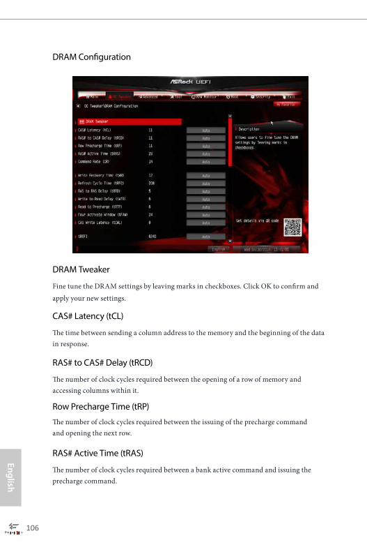
106 107
English
Fatal1ty Z97 Professional Series
DRAM Configuration
DRAM Tweaker
Fine tune the DRAM settings by leaving marks in checkboxes. Click OK to confirm and apply your new settings.
CAS# Latency (tCL)
The time between sending a column address to the memory and the beginning of the data in response.
RAS# to CAS# Delay (tRCD)
The number of clock cycles required between the opening of a row of memory and accessing columns within it.
Row Precharge Time (tRP)
The number of clock cycles required between the issuing of the precharge command and opening the next row.
RAS# Active Time (tRAS)
The number of clock cycles required between a bank active command and issuing the precharge command.
106 107
Engl
ish
Fatal1ty Z97 Professional Series
Command Rate (CR)
The delay between when a memory chip is selected and when the first active command can be issued.
Write Recovery Time (tWR)The amount of delay that must elapse after the completion of a valid write operation, before an active bank can be precharged.
Refresh Cycle Time (tRFC)The number of clocks from a Refresh command until the first Activate command to the same rank.
RAS to RAS Delay (tRRD) The number of clocks between two rows activated in different banks of the same rank.
Write to Read Delay (tWTR)The number of clocks between the last valid write operation and the next read command to the same internal bank.
Read to Precharge (tRTP)The number of clocks that are inserted between a read command to a row pre-charge command to the same rank.
Four Activate Window (tFAW)The time window in which four activates are allowed the same rank.
CAS Write Latency (tCWL)Configure CAS Write Latency.
tREFIConfigure refresh cycles at an average periodic interval.
tCKEConfigure the period of time the DDR3 initiates a minimum of one refresh command internally once it enters Self-Refresh mode.
tRDRDConfigure between module read to read delay.
108 109
English
Fatal1ty Z97 Professional Series
tRDRDDRConfigure between module read to read delay from different ranks.
tRDRDDDUse this to change DRAM tRWSR Auto/Manual settings. The default is [Auto].
tWRRDConfigure between module write to read delay.
tWRRDDRConfigure between module write to read delay from different ranks.
tWRRDDDUse this to change DRAM tRRSR Auto/Manual settings. The default is [Auto].
Configure between module write to read delay from different DIMMs.
tWRWRConfigure between module write to write delay.
tWRWRDRConfigure between module write to write delay from different ranks.
tWRWRDDConfigure between module write to write delay from different DIMMs.
tRDWRConfigure between module read to write delay.
tRDWRDRConfigure between module read to write delay from different ranks.
tRDWRDDConfigure between module read to write delay from different DIMMs.
RTL (CHA)Configure round trip latency for channel A.
RTL (CHB)Configure round trip latency for channel B.
108 109
Engl
ish
Fatal1ty Z97 Professional Series
IO-L (CHA)Configure IO latency for channel A.
IO-L (CHB)Configure IO latency for channel B.
ODT WR (CHA)Configure the memory on die termination resistors' WR for channel A.
ODT WR (CHB)Configure the memory on die termination resistors' WR for channel B.
ODT NOM (CHA)Use this to change ODT (CHA) Auto/Manual settings. The default is [Auto].
ODT NOM (CHB)Use this to change ODT (CHB) Auto/Manual settings. The default is [Auto].
Command Tri StateEnable for DRAM power saving.
MRC Fast BootEnable Memory Fast Boot to skip DRAM memory training for booting faster.
DIMM Exit ModeSelect Slow Exit to reduce power consumption, or Fast Exit for better performance.
FIVR Configuration
FIVR Switch Frequency SignatureSelect whether to boost or lower the FIVR Switch Frequency.
FIVR Switch Frequency OffsetConfigure the percentage of frequency boost or deduction.
Vcore Override VoltageAdd voltage to the Vcore when the system is under heavy load.
Vcore Voltage Additional OffsetConfigure the dynamic Vcore voltage added to the Vcore.
110 111
English
Fatal1ty Z97 Professional Series
CPU Cache Override VoltageAdd voltage to the CPU Cache when the system is under heavy load.
CPU Cache Voltage OffsetConfigure the voltage for the CPU Cache. Setting the voltage higher may increase system stability when overclocking.
System Agent Voltage Offset
Configure the voltage for the System Agent. Setting the voltage higher may increase system stability when overclocking.
CPU Analog IO Voltage OffsetCPU I/O Analog Voltage.
CPU Digital IO Voltage OffsetCPU I/O Digital Voltage.
CPU Integrated VR Faults
Disable FIVR Faults to raise the threshold to trigger CPU over current protection and over voltage protection for better overclocking capabilities.
CPU Integrated VR Efficiency ModeEnable FIVR Efficiency Management for power saving. Disable for better performance and overclocking capabilities.
Voltage Configuration
CPU Input VoltageConfigure the voltage for the CPU.
CPU Load-Line Calibration
CPU Load-Line Calibration helps prevent CPU voltage droop when the system is under heavy load.
CPU Input Offset
The fixed external voltage input to the CPU.
DRAM VoltageUse this to configure DRAM Voltage.

110 111
Engl
ish
Fatal1ty Z97 Professional Series
PCH 1.05V VoltageChipset 1.05V Voltage. Use default settings for best performance.
PCH 1.5V VoltageI/O 1.5V Voltage. Use default settings for best performance.
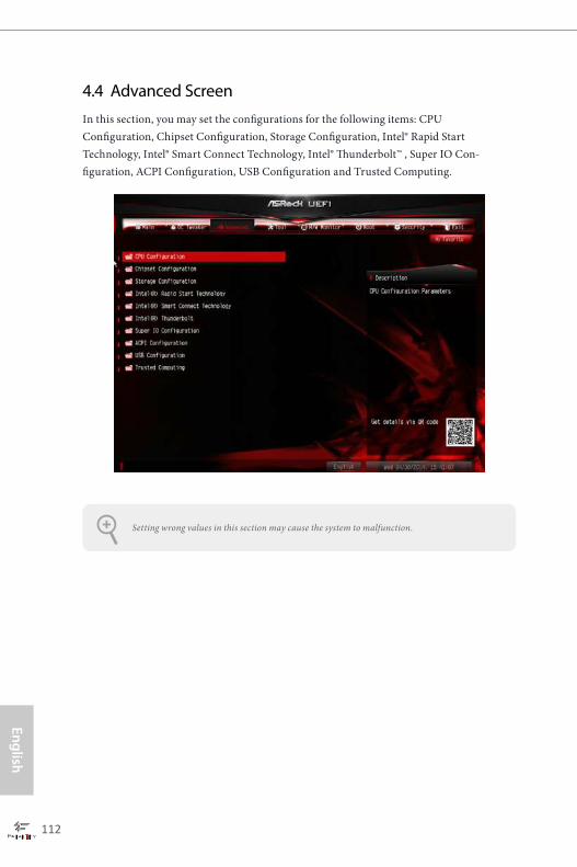
112 113
English
Fatal1ty Z97 Professional Series
4.4 Advanced ScreenIn this section, you may set the configurations for the following items: CPU Configuration, Chipset Configuration, Storage Configuration, Intel® Rapid Start Technology, Intel® Smart Connect Technology, Intel® Thunderbolt™ , Super IO Con-figuration, ACPI Configuration, USB Configuration and Trusted Computing.
Setting wrong values in this section may cause the system to malfunction.
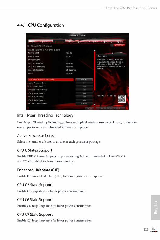
112 113
Engl
ish
Fatal1ty Z97 Professional Series
4.4.1 CPU Configuration
Intel Hyper Threading Technology
Intel Hyper Threading Technology allows multiple threads to run on each core, so that the overall performance on threaded software is improved.
Active Processor CoresSelect the number of cores to enable in each processor package.
CPU C States SupportEnable CPU C States Support for power saving. It is recommended to keep C3, C6 and C7 all enabled for better power saving.
Enhanced Halt State (C1E)Enable Enhanced Halt State (C1E) for lower power consumption.
CPU C3 State SupportEnable C3 sleep state for lower power consumption.
CPU C6 State SupportEnable C6 deep sleep state for lower power consumption.
CPU C7 State SupportEnable C7 deep sleep state for lower power consumption.
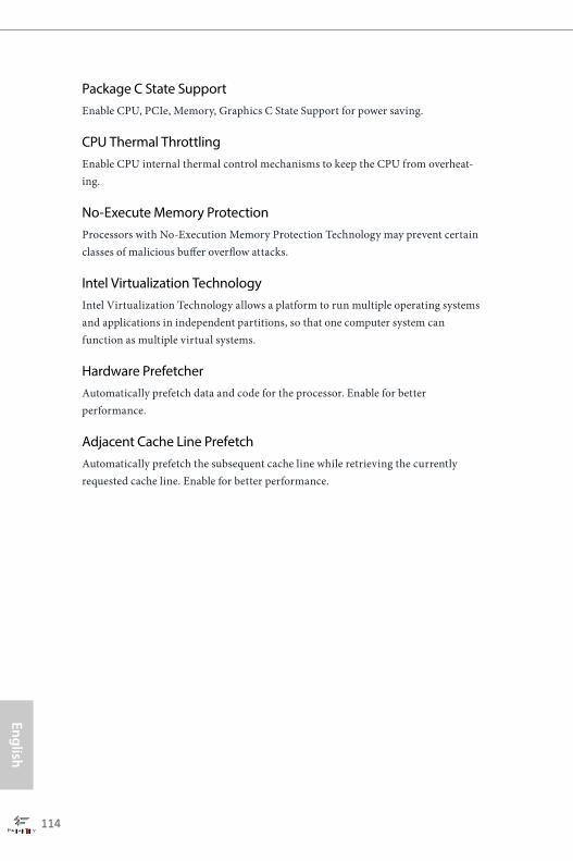
114 115
English
Fatal1ty Z97 Professional Series
Package C State SupportEnable CPU, PCIe, Memory, Graphics C State Support for power saving.
CPU Thermal ThrottlingEnable CPU internal thermal control mechanisms to keep the CPU from overheat-ing.
No-Execute Memory ProtectionProcessors with No-Execution Memory Protection Technology may prevent certain classes of malicious buffer overflow attacks.
Intel Virtualization TechnologyIntel Virtualization Technology allows a platform to run multiple operating systems and applications in independent partitions, so that one computer system can function as multiple virtual systems.
Hardware PrefetcherAutomatically prefetch data and code for the processor. Enable for better performance.
Adjacent Cache Line PrefetchAutomatically prefetch the subsequent cache line while retrieving the currently requested cache line. Enable for better performance.
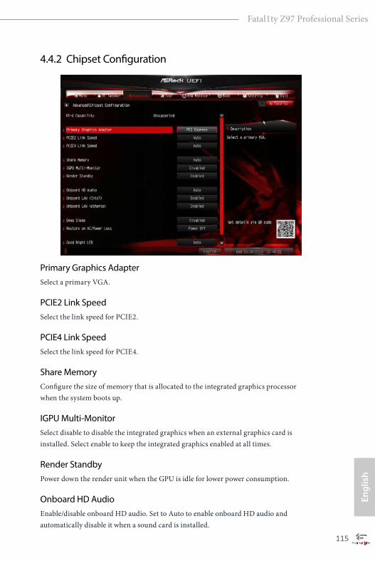
114 115
Engl
ish
Fatal1ty Z97 Professional Series
4.4.2 Chipset Configuration
Primary Graphics AdapterSelect a primary VGA.
PCIE2 Link SpeedSelect the link speed for PCIE2.
PCIE4 Link SpeedSelect the link speed for PCIE4.
Share MemoryConfigure the size of memory that is allocated to the integrated graphics processor when the system boots up.
IGPU Multi-MonitorSelect disable to disable the integrated graphics when an external graphics card is installed. Select enable to keep the integrated graphics enabled at all times.
Render StandbyPower down the render unit when the GPU is idle for lower power consumption.
Onboard HD AudioEnable/disable onboard HD audio. Set to Auto to enable onboard HD audio and automatically disable it when a sound card is installed.

116 117
English
Fatal1ty Z97 Professional Series
Onboard LAN (Intel)
Enable or disable the onboard network interface controller (Intel® I218V).
Onboard LAN (Atheros)
Enable or disable the onboard network interface controller (Qualcomm® Atheros® KillerTM
E2200 Series).
Deep SleepConfigure deep sleep mode for power saving when the computer is shut down.
Restore on AC/Power LossSelect the power state after a power failure. If [Power Off] is selected, the power will remain off when the power recovers. If [Power On] is selected, the system will start to boot up when the power recovers.
Good Night LED
By enabling Good Night LED, the Power/HDD LEDs will be switched off when the system is on. It will also automatically switch off the Power and Keyboard LEDs when the system enters into Standby/Hibernation mode.
Onboard Debug Port LEDEnable/disable the onboard Dr. Debug LED.
116 117
Engl
ish
Fatal1ty Z97 Professional Series
4.4.3 Storage Configuration
SATA Controller(s)Enable/disable the SATA controllers.
SATA Mode SelectionIDE: For better compatibility.
AHCI: Supports new features that improve performance.
RAID: Combine multiple disk drives into a logical unit.
SATA Aggressive Link Power ManagementSATA Aggressive Link Power Management allows SATA devices to enter a low power state during periods of inactivity to save power. It is only supported by AHCI mode.
AHCI (Advanced Host Controller Interface) supports NCQ and other new features that will improve SATA disk performance but IDE mode does not have these advantages.
118 119
English
Fatal1ty Z97 Professional Series
Dynamic Storage Accelerator
Keep this option enabled for higher HDD and SDD I/O performance, lower latency and increased system responsiveness.
Hard Disk S.M.A.R.T.S.M.A.R.T stands for Self-Monitoring, Analysis, and Reporting Technology. It is a monitoring system for computer hard disk drives to detect and report on various indicators of reliability.
M2_2/SATA3_4, SATA3_5 Switch
Auto: M2_2/SATA3_4, SATA3_5 auto switch Force_SATA: Switch to SATA3_4, SATA3_5 Force_M2_2: Switch to M2_2
ASMedia SATA3 ModeIDE: For better compatibility.
AHCI: Supports new features that improve performance.

118 119
Engl
ish
Fatal1ty Z97 Professional Series
4.4.4 Intel® Rapid Start Technology
Intel® Rapid Start TechnologyIntel® Rapid Start Technology is a new zero power hibernation mode which allows users to resume in just 5-6 seconds.

120 121
English
Fatal1ty Z97 Professional Series
4.4.5 Intel® Smart Connect Technology
Intel® Smart Connect Technology
Intel® Smart Connect Technology automatically updates your email and social networks, such as Twitter, Facebook, etc. while the computer is in sleep mode.

120 121
Engl
ish
Fatal1ty Z97 Professional Series
4.4.6 Intel® Thunderbolt™
Intel Thunderbolt™ TechnologyEnable or disable the Intel® Thunderbolt™ function.
Security LevelSelect Legacy to skip the Windows certification checking process for Thunderbolt™ devices. Select Unique ID for checking the Windows certification, and show warning messages if the devices aren't certified. Or select DP++ to support DP 1.2.
Ignore Thunderbolt™ Option RomEnable to skip Thunderbolt™ Option ROM during POST for faster boot speed.
TBT Device IO resource SupportEnable IO Resource Support if your older Thunderbolt devices have trouble working properly.
Thunderbolt™ PCIe Cache-line SizeConfigure the cache-line size of the Thunderbolt PCIe subtree.
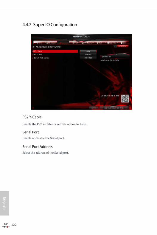
122 123
English
Fatal1ty Z97 Professional Series
4.4.7 Super IO Configuration
PS2 Y-Cable
Enable the PS2 Y-Cable or set this option to Auto.
Serial PortEnable or disable the Serial port.
Serial Port AddressSelect the address of the Serial port.
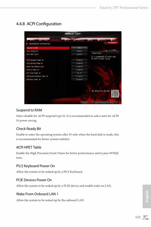
122 123
Engl
ish
Fatal1ty Z97 Professional Series
4.4.8 ACPI Configuration
Suspend to RAMSelect disable for ACPI suspend type S1. It is recommended to select auto for ACPI S3 power saving.
Check Ready BitEnable to enter the operating system after S3 only when the hard disk is ready, this is recommended for better system stability.
ACPI HPET TableEnable the High Precision Event Timer for better performance and to pass WHQL tests.
PS/2 Keyboard Power OnAllow the system to be waked up by a PS/2 Keyboard.
PCIE Devices Power OnAllow the system to be waked up by a PCIE device and enable wake on LAN.
Wake From Onboard LAN 1
Allow the system to be waked up by the onboard LAN.

124 125
English
Fatal1ty Z97 Professional Series
Ring-In Power On
Allow the system to be waked up by onboard COM port modem Ring-In signals.
RTC Alarm Power OnAllow the system to be waked up by the real time clock alarm. Set it to By OS to let it be handled by your operating system.
USB Keyboard/Remote Power OnAllow the system to be waked up by an USB keyboard or remote controller.
USB Mouse Power OnAllow the system to be waked up by an USB mouse.

124 125
Engl
ish
Fatal1ty Z97 Professional Series
4.4.9 USB Configuration
USB ControllerEnable or disable all the USB ports.
Intel USB 3.0 ModeSelect Intel® USB 3.0 controller mode. Set [Smart Auto] to keep the USB 3.0 driver enabled after rebooting (USB 3.0 is enabled in BIOS). Set [Auto] to automatically enable the USB 3.0 driver after entering the OS (USB 3.0 is disabled in BIOS). Set [Enabled] to keep the USB 3.0 driver enabled (Must install driver to use USB devices under Windows® 7). Set [Disabled] to disable the USB 3.0 ports.
Legacy USB SupportEnable or disable Legacy OS Support for USB 2.0 devices. If you encounter USB compatibility issues it is recommended to disable legacy USB support. Select UEFI Setup Only to support USB devices under the UEFI setup and Windows/Linux operating systems only.
Legacy USB 3.0 SupportEnable or disable Legacy OS Support for USB 3.0 devices. If you encounter USB compatibility issues it is recommended to disable legacy USB support. Select UEFI Setup Only to support USB devices under the UEFI setup and Windows/Linux operating systems only.

126 127
English
Fatal1ty Z97 Professional Series
USB Compatibility PatchIf your USB devices (i.e. USB mouse or storage) encounter compatibility problems, please enable this option to fix it. Please note that after enabling this option, it is normal that the system will postpone booting up after pressing the power button.

126 127
Engl
ish
Fatal1ty Z97 Professional Series
4.4.10 Trusted Computing
Security Device SupportEnable or disable BIOS support for security device.
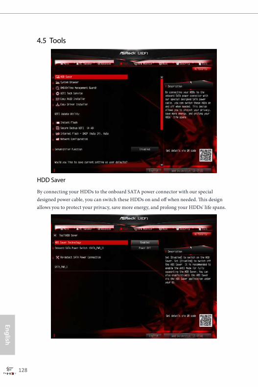
128 129
English
Fatal1ty Z97 Professional Series
4.5 Tools
HDD Saver
By connecting your HDDs to the onboard SATA power connector with our special designed power cable, you can switch these HDDs on and off when needed. This design allows you to protect your privacy, save more energy, and prolong your HDDs' life spans.
128 129
Engl
ish
Fatal1ty Z97 Professional Series
HDD Saver Technology
Set [Enabled] to switch on the HDD Saver. Set [Disabled] to switch off the HDD Saver. It is recommended to enable the AHCI Mode to fully support the HDD Saver. You can also enable/disable the HDD Saver via the HDD Saver application under your OS.
Onboard SATA Power Switch (SATA_PWR_1)
Set [Power On] to switch on the onboard SATA Power Connector. Set [Power Off] to switch off the onboard SATA Power Connector.
Re-detect SATA Power Connection
Re-detect your SATA Power connection. It is recommended to proceed the re-detection for any changes of your HDD configuration. You can also proceed the re-detection via the HDD Saver application under your OS.
System BrowserASRock System Browser shows the overview of your current PC and the devices connected.
OMG (Online Management Guard)Administrators are able to establish an internet curfew or restrict internet access at specified times via OMG. You may schedule the starting and ending hours of internet access granted to other users. In order to prevent users from bypassing OMG, guest accounts without permission to modify the system time are required.
UEFI Tech ServiceContact ASRock Tech Service if you are having trouble with your PC. Please setup network configuration before using UEFI Tech Service.
Easy RAID InstallerEasy RAID Installer helps you to copy the RAID driver from the support CD to your USB storage device. After copying the drivers please change the SATA mode to RAID, then you can start installing the operating system in RAID mode.
Easy Driver InstallerFor users that don’t have an optical disk drive to install the drivers from our support CD, Easy Driver Installer is a handy tool in the UEFI that installs the LAN driver to your system via an USB storage device, then downloads and installs the other required drivers automatically.
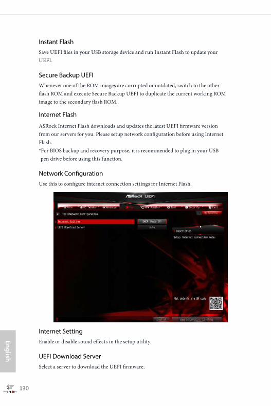
130 131
English
Fatal1ty Z97 Professional Series
Instant FlashSave UEFI files in your USB storage device and run Instant Flash to update your UEFI.
Secure Backup UEFIWhenever one of the ROM images are corrupted or outdated, switch to the other flash ROM and execute Secure Backup UEFI to duplicate the current working ROM image to the secondary flash ROM.
Internet Flash
ASRock Internet Flash downloads and updates the latest UEFI firmware version from our servers for you. Please setup network configuration before using Internet Flash. *For BIOS backup and recovery purpose, it is recommended to plug in your USB pen drive before using this function.
Network ConfigurationUse this to configure internet connection settings for Internet Flash.
Internet SettingEnable or disable sound effects in the setup utility.
UEFI Download ServerSelect a server to download the UEFI firmware.

130 131
Engl
ish
Fatal1ty Z97 Professional Series
Dehumidifier FunctionIf Dehumidifier Function is enabled, the computer will power on automatically to dehumidify the system after entering S4/S5 state.
Dehumidifier PeriodConfigure the period of time until the computer powers on and enables Dehumidifier after entering S4/S5 state.
Dehumidifier DurationConfigure the duration of the dehumidifying process before it returns to S4/S5 state.
Dehumidifier CPU Fan SettingConfigure the speed of the CPU fan while Dehumidifier is enabled. The higher the value, the faster the fan speed.
Max: 255
Min: 1
Save User DefaultType a profile name and press enter to save your settings as user default.
Load User DefaultLoad previously saved user defaults.
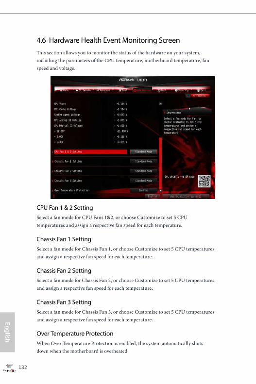
132 133
English
Fatal1ty Z97 Professional Series
4.6 Hardware Health Event Monitoring ScreenThis section allows you to monitor the status of the hardware on your system, including the parameters of the CPU temperature, motherboard temperature, fan speed and voltage.
CPU Fan 1 & 2 SettingSelect a fan mode for CPU Fans 1&2, or choose Customize to set 5 CPU temperatures and assign a respective fan speed for each temperature.
Chassis Fan 1 SettingSelect a fan mode for Chassis Fan 1, or choose Customize to set 5 CPU temperatures and assign a respective fan speed for each temperature.
Chassis Fan 2 SettingSelect a fan mode for Chassis Fan 2, or choose Customize to set 5 CPU temperatures and assign a respective fan speed for each temperature.
Chassis Fan 3 SettingSelect a fan mode for Chassis Fan 3, or choose Customize to set 5 CPU temperatures and assign a respective fan speed for each temperature.
Over Temperature ProtectionWhen Over Temperature Protection is enabled, the system automatically shuts down when the motherboard is overheated.
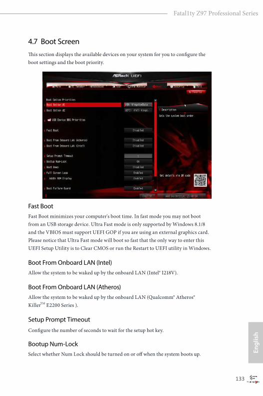
132 133
Engl
ish
Fatal1ty Z97 Professional Series
4.7 Boot ScreenThis section displays the available devices on your system for you to configure the boot settings and the boot priority.
Fast BootFast Boot minimizes your computer's boot time. In fast mode you may not boot from an USB storage device. Ultra Fast mode is only supported by Windows 8.1/8 and the VBIOS must support UEFI GOP if you are using an external graphics card. Please notice that Ultra Fast mode will boot so fast that the only way to enter this UEFI Setup Utility is to Clear CMOS or run the Restart to UEFI utility in Windows.
Boot From Onboard LAN (Intel)Allow the system to be waked up by the onboard LAN (Intel® I218V).
Boot From Onboard LAN (Atheros)Allow the system to be waked up by the onboard LAN (Qualcomm® Atheros® KillerTM E2200 Series ).
Setup Prompt Timeout
Configure the number of seconds to wait for the setup hot key.
Bootup Num-LockSelect whether Num Lock should be turned on or off when the system boots up.
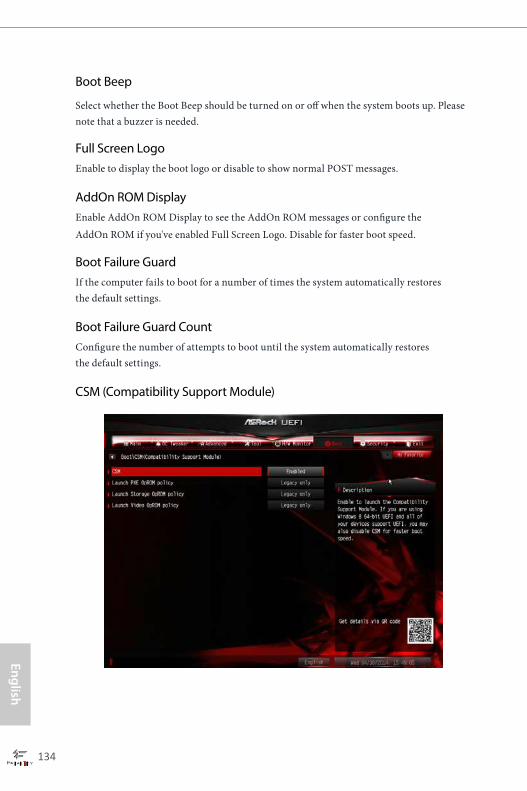
134 135
English
Fatal1ty Z97 Professional Series
Boot Beep
Select whether the Boot Beep should be turned on or off when the system boots up. Please note that a buzzer is needed.
Full Screen LogoEnable to display the boot logo or disable to show normal POST messages.
AddOn ROM DisplayEnable AddOn ROM Display to see the AddOn ROM messages or configure the AddOn ROM if you've enabled Full Screen Logo. Disable for faster boot speed.
Boot Failure GuardIf the computer fails to boot for a number of times the system automatically restores the default settings.
Boot Failure Guard CountConfigure the number of attempts to boot until the system automatically restores the default settings.
CSM (Compatibility Support Module)

134 135
Engl
ish
Fatal1ty Z97 Professional Series
CSM Enable to launch the Compatibility Support Module. Please do not disable unless you’re running a WHCK test. If you are using Windows 8.1/8 64-bit and all of your devices support UEFI, you may also disable CSM for faster boot speed.
Launch PXE OpROM Policy Select UEFI only to run those that support UEFI option ROM only. Select Legacy only to run those that support legacy option ROM only. Do not launch?
Launch Storage OpROM PolicySelect UEFI only to run those that support UEFI option ROM only. Select Legacy only to run those that support legacy option ROM only. Do not launch?
Launch Video OpROM Policy Select UEFI only to run those that support UEFI option ROM only. Select Legacy only to run those that support legacy option ROM only. Do not launch?
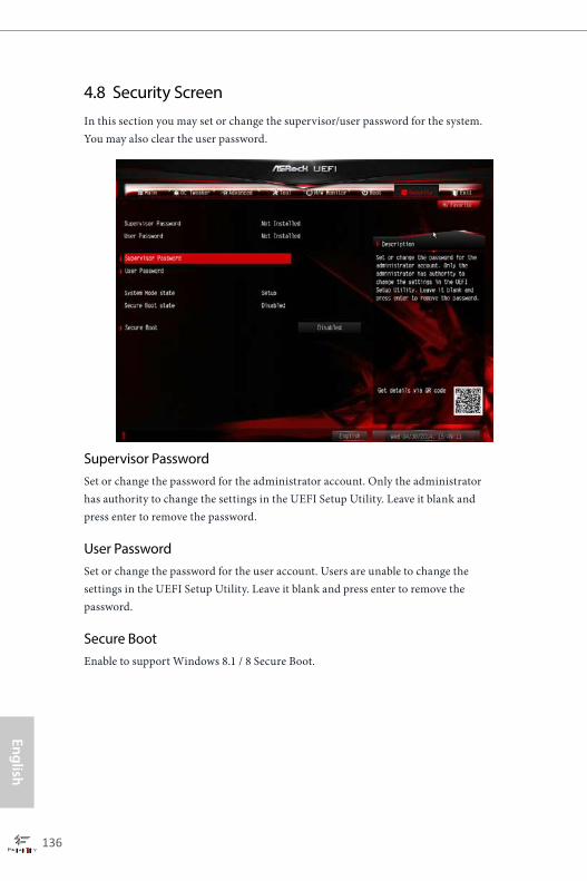
136 137
English
Fatal1ty Z97 Professional Series
4.8 Security ScreenIn this section you may set or change the supervisor/user password for the system. You may also clear the user password.
Supervisor PasswordSet or change the password for the administrator account. Only the administrator has authority to change the settings in the UEFI Setup Utility. Leave it blank and press enter to remove the password.
User PasswordSet or change the password for the user account. Users are unable to change the settings in the UEFI Setup Utility. Leave it blank and press enter to remove the password.
Secure BootEnable to support Windows 8.1 / 8 Secure Boot.
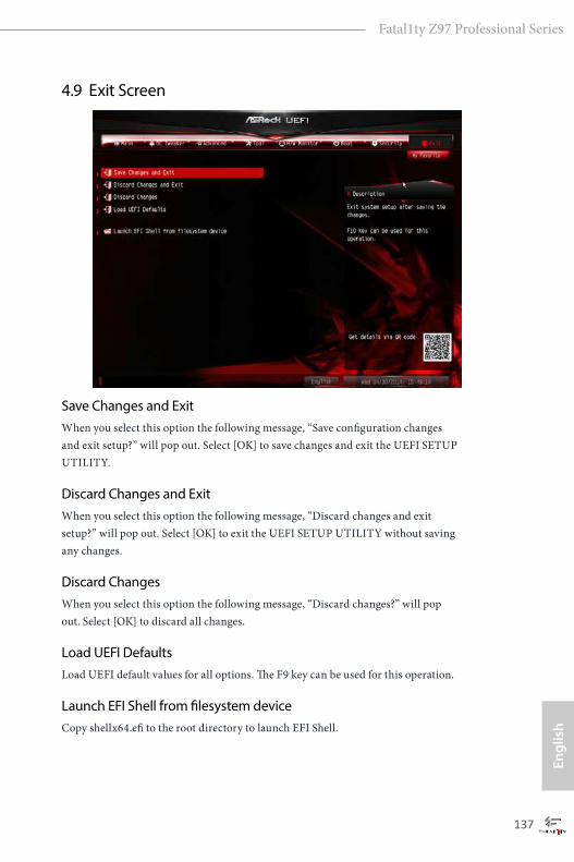
136 137
Engl
ish
Fatal1ty Z97 Professional Series
4.9 Exit Screen
Save Changes and ExitWhen you select this option the following message, “Save configuration changes and exit setup?” will pop out. Select [OK] to save changes and exit the UEFI SETUP UTILITY.
Discard Changes and ExitWhen you select this option the following message, “Discard changes and exit setup?” will pop out. Select [OK] to exit the UEFI SETUP UTILITY without saving any changes.
Discard ChangesWhen you select this option the following message, “Discard changes?” will pop out. Select [OK] to discard all changes.
Load UEFI DefaultsLoad UEFI default values for all options. The F9 key can be used for this operation.
Launch EFI Shell from filesystem deviceCopy shellx64.efi to the root directory to launch EFI Shell.

138 PB
English
Fatal1ty Z97 Professional Series
Contact Information
If you need to contact ASRock or want to know more about ASRock, you’re welcome to visit ASRock’s website at http://www.asrock.com; or you may contact your dealer for further information. For technical questions, please submit a support request form at http://www.asrock.com/support/tsd.asp
ASRock Incorporation2F., No.37, Sec. 2, Jhongyang S. Rd., Beitou District,
Taipei City 112, Taiwan (R.O.C.)
ASRock EUROPE B.V.Bijsterhuizen 3151
6604 LV Wijchen
The Netherlands
Phone: +31-24-345-44-33
Fax: +31-24-345-44-38
ASRock America, Inc.13848 Magnolia Ave, Chino, CA91710
U.S.A.
Phone: +1-909-590-8308
Fax: +1-909-590-1026