user manual - bitgravityasrock.pc.cdn.bitgravity.com/manual/fatal1ty z370...you are entitled to a...
TRANSCRIPT
Z370 Professional Gaming i7
User Manual
Version 1.0Published December 2016
Copyright©2016 ASRock INC. All rights reserved.

Version 1.0 Published August 2017 Copyright©2017 ASRock INC. All rights reserved.
Copyright Notice:No part of this documentation may be reproduced, transcribed, transmitted, or translated in any language, in any form or by any means, except duplication of documentation by the purchaser for backup purpose, without written consent of ASRock Inc.
Products and corporate names appearing in this documentation may or may not be registered trademarks or copyrights of their respective companies, and are used only for identification or explanation and to the owners’ benefit, without intent to infringe.
Disclaimer:Specifications and information contained in this documentation are furnished for informational use only and subject to change without notice, and should not be constructed as a commitment by ASRock. ASRock assumes no responsibility for any errors or omissions that may appear in this documentation.
With respect to the contents of this documentation, ASRock does not provide warranty of any kind, either expressed or implied, including but not limited to the implied warranties or conditions of merchantability or fitness for a particular purpose.
In no event shall ASRock, its directors, officers, employees, or agents be liable for any indirect, special, incidental, or consequential damages (including damages for loss of profits, loss of business, loss of data, interruption of business and the like), even if ASRock has been advised of the possibility of such damages arising from any defect or error in the documentation or product.
This device complies with Part 15 of the FCC Rules. Operation is subject to the following two conditions: (1) this device may not cause harmful interference, and (2) this device must accept any interference received, including interference that
may cause undesired operation.
CALIFORNIA, USA ONLYThe Lithium battery adopted on this motherboard contains Perchlorate, a toxic substance controlled in Perchlorate Best Management Practices (BMP) regulations passed by the California Legislature. When you discard the Lithium battery in California, USA, please follow the related regulations in advance.“Perchlorate Material-special handling may apply, see www.dtsc.ca.gov/hazardouswaste/perchlorate”
ASRock Website: http://www.asrock.com

AUSTRALIA ONLYOur goods come with guarantees that cannot be excluded under the Australian Consumer Law. You are entitled to a replacement or refund for a major failure and compensation for any other reasonably foreseeable loss or damage caused by our goods. You are also entitled to have the goods repaired or replaced if the goods fail to be of acceptable quality and the failure does not amount to a major failure. If you require assistance please call ASRock Tel : +886-2-28965588 ext.123 (Standard International call charges apply)
The terms HDMI™ and HDMI High-Definition Multimedia Interface, and the HDMI logo are trademarks or registered trademarks of HDMI Licensing LLC in the United States and other countries.

CE WarningThis device complies with directive 2014/53/EU issued by the Commision of the European Community.
This equipment complies with EU radiation exposure limits set forth for an uncontrolled environment. This equipment should be installed and operated with minimum distance 20cm between the radiator & your body.
Operations in the 5.15-5.35GHz band are restricted to indoor usage only.
Radio transmit power per transceiver type
Function Frequency Maximum Output Power (EIRP)
WiFi
2400-2483.5 MHz 18.5 + / -1.5 dbm5150-5250 MHz 21.5 + / -1.5 dbm
5250-5350 MHz18.5 + / -1.5 dbm (no TPC)
21.5 + / -1.5 dbm (TPC)
5470-5725 MHz25.5 + / -1.5 dbm (no TPC)
28.5 + / -1.5 dbm (TPC)Bluetooth 2400-2483.5 MHz 8.5 + / -1.5 dbm

Who knew that at age 19, I would be a World Champion PC gamer. When I was 13, I actually played competitive billiards in professional tournaments and won four or five games off guys who played at the highest level. I actually thought of making a career of it, but at that young age situations change rapidly. Because I’ve been blessed with great hand-eye coordination and a grasp of mathematics (an important element in video gaming) I gravitated to that activity.
GOING PROI started professional gaming in 1999 when I entered the CPL (Cyberathlete Professional League) tournament in Dallas and won $4,000 for coming in third place. Emerging as one of the top players in the United States, a company interested in sponsoring me flew me to Sweden to compete against the top 12 players in the world. I won 18 straight games, lost none, and took first place, becoming the number one ranked Quake III player in the world in the process. Two months later I followed that success by traveling to Dallas and defending my title as the world’s best Quake III player, winning the $40,000 grand prize. From there I entered competitions all over the world, including Singapore, Korea, Germany, Australia, Holland and Brazil in addition to Los Angeles, New York and St. Louis.
WINNING STREAKI was excited to showcase my true gaming skills when defending my title as CPL Champion of the year at the CPL Winter 2001 because I would be competing in a totally different first person shooter (fps) game, Alien vs. Predator II. I won that competition and walked away with a new car. The next year I won the same title playing Unreal Tournament 2003, becoming the only three-time CPL champion of the year. And I did it playing a different game each year, something no one else has ever done and a feat of which I am extremely proud.
At QuakeCon 2002, I faced off against my rival ZeRo4 in one of the most highly anticipated matches of the year, winning in a 14 to (-1) killer victory. Competing at Quakecon 2004, I became the World’s 1st Doom3 Champion by defeating Daler in a series of very challenging matches and earning $25,000 for the victory.
Since then Fatal1ty has traveled the globe to compete against the best in the world, winning prizes and acclaim, including the 2005 CPL World Tour Championship in New York City for a $150,000 first place triumph. In August 2007, Johnathan was awarded the first ever Lifetime Achievement Award in the four year history of the eSports-Award for “showing exceptional sportsmanship, taking part in shaping eSports into what it is today and for being the prime representative of this young sport. He has become the figurehead for eSports worldwide”.
Fatal1ty Story

LIVIN’ LARGESince my first big tournament wins, I have been a “Professional Cyberathlete”, traveling the world and livin’ large with lots of International media coverage on outlets such as MTV, ESPN and a 60 Minutes segment on CBS to name only a few. It's unreal - it's crazy. I’m living a dream by playing video games for a living. I’ve always been athletic and took sports like hockey and football very seriously, working out and training hard. This discipline helps me become a better gamer and my drive to be the best has opened the doors necessary to become a professional.
A DREAMNow, another dream is being realized – building the ultimate gaming computer, made up of the best parts under my own brand. Quality hardware makes a huge difference in competitions…a couple more frames per second and everything gets really nice. It’s all about getting the computer processing faster and allowing more fluid movement around the maps.
My vision for Fatal1ty hardware is to allow gamers to focus on the game without worrying about their equipment, something I’ve preached since I began competing. I don’t want to worry about my equipment. I want to be there – over and done with - so I can focus on the game. I want it to be the fastest and most stable computer equipment on the face of the planet, so quality is what Fatal1ty Brand products represent.
Johnathan “Fatal1ty” Wendel
The Fatal1ty name, Fatal1ty logos and the Fatal1ty likeness are registered trademarks of Fatal1ty, Inc., and are used under license. © 2016 Fatal1ty, Inc. All rights reserved. All other trademarks are the property of their respective owners.

Contents
Chapter 1 Introduction 1
1.1 Package Contents 1
1.2 Specifications 2
1.3 Motherboard Layout 8
1.4 I/O Panel 10
1.5 WiFi-802.11ac Module and ASRock WiFi 2.4/5 GHz Antenna 12
Chapter 2 Installation 14
2.1 Installing the CPU 15
2.2 Installing the CPU Fan and Heatsink 18
2.3 Installing Memory Modules (DIMM) 19
2.4 Expansion Slots (PCI and PCI Express Slots) 21
2.6 Onboard Headers and Connectors 23
2.7 Smart Switches 29
2.8 Dr. Debug 30
2.9 SLITM and Quad SLITM Operation Guide 32
2.9.1 Installing Two SLITM-Ready Graphics Cards 32
2.9.2 Driver Installation and Setup 34
2.10 CrossFireXTM , 3-Way CrossFireXTM and Quad CrossFireXTM Operation Guide 35
2.10.1 Installing Two CrossFireXTM-Ready Graphics Cards 35
2.10.2 Installing Three CrossFireXTM-Ready Graphics Cards 37
2.10.3 Driver Installation and Setup 38
Chapter 3 Software and Utilities Operation 47
3.1 Installing Drivers 47
3.2 F-Stream 48
3.3 ASRock Live Update & APP Shop 51
3.3.1 UI Overview 51
3.3.2 Apps 52
3.3.3 BIOS & Drivers 55
3.3.4 Setting 56
3.4 Creative SoundBlaster Cinema3 57
3.5 ASRock RGB LED 58
Chapter 4 UEFI SETUP UTILITY 60
4.1 Introduction 60
4.2 EZ Mode 61
4.3 Advanced Mode 62
4.3.1 UEFI Menu Bar 62
4.3.2 Navigation Keys 63
4.4 Main Screen 64
4.5 OC Tweaker Screen 65
4.6 Advanced Screen 77
4.6.1 CPU Configuration 78
4.6.2 Chipset Configuration 80
4.6.3 Storage Configuration 83
4.6.4 Intel® Thunderbolt 85
4.6.5 Super IO Configuration 86
4.6.6 ACPI Configuration 87
4.6.7 USB Configuration 88
4.6.8 Trusted Computing 89
4.7 Tools 90
4.8 Hardware Health Event Monitoring Screen 93
4.9 Security Screen 96
4.10 Boot Screen 97
4.11 Exit Screen 100
Engl
ish
Fatal1ty Z370 Professional Gaming i7 Series
1
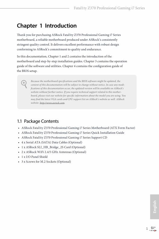
Chapter 1 IntroductionThank you for purchasing ASRock Fatal1ty Z370 Professional Gaming i7 Series motherboard, a reliable motherboard produced under ASRock’s consistently stringent quality control. It delivers excellent performance with robust design conforming to ASRock’s commitment to quality and endurance.
In this documentation, Chapter 1 and 2 contains the introduction of the motherboard and step-by-step installation guides. Chapter 3 contains the operation guide of the software and utilities. Chapter 4 contains the configuration guide of the BIOS setup.
1.1 Package Contents• ASRock Fatal1ty Z370 Professional Gaming i7 Series Motherboard (ATX Form Factor)• ASRock Fatal1ty Z370 Professional Gaming i7 Series Quick Installation Guide • ASRock Fatal1ty Z370 Professional Gaming i7 Series Support CD • 4 x Serial ATA (SATA) Data Cables (Optional)• 1 x ASRock SLI_HB_Bridge_2S Card (Optional)• 2 x ASRock WiFi 2.4/5 GHz Antennas (Optional)• 1 x I/O Panel Shield • 3 x Screws for M.2 Sockets (Optional)
Because the motherboard specifications and the BIOS software might be updated, the content of this documentation will be subject to change without notice. In case any modi-fications of this documentation occur, the updated version will be available on ASRock’s website without further notice. If you require technical support related to this mother-board, please visit our website for specific information about the model you are using. You may find the latest VGA cards and CPU support list on ASRock’s website as well. ASRock website http://www.asrock.com.
English
2
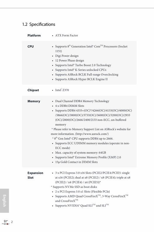
1.2 Specifications
Platform • ATX Form Factor
CPU • Supports 8th Generation Intel® CoreTM Processors (Socket 1151)
• Digi Power design• 12 Power Phase design• Supports Intel® Turbo Boost 2.0 Technology• Supports Intel® K-Series unlocked CPUs• Supports ASRock BCLK Full-range Overclocking• Supports ASRock Hyper BCLK Engine II
Chipset • Intel® Z370
Memory • Dual Channel DDR4 Memory Technology• 4 x DDR4 DIMM Slots• Supports DDR4 4333+(OC)*/4266(OC)/4133(OC)/4000(OC)
/3866(OC)/3800(OC)/3733(OC)/3600(OC)/3200(OC)/2933 (OC)/2800(OC)/2666/2400/2133 non-ECC, un-buffered memory
* Please refer to Memory Support List on ASRock's website for more information. (http://www.asrock.com/) * 8th Gen Intel® CPU supports DDR4 up to 2666.• Supports ECC UDIMM memory modules (operate in non-
ECC mode)• Max. capacity of system memory: 64GB• Supports Intel® Extreme Memory Profile (XMP) 2.0• 15μ Gold Contact in DIMM Slots
Expansion Slot
• 3 x PCI Express 3.0 x16 Slots (PCIE2/PCIE4/PCIE5: single at x16 (PCIE2); dual at x8 (PCIE2) / x8 (PCIE4); triple at x8 (PCIE2) / x4 (PCIE4) / x4 (PCIE5))*
* Supports NVMe SSD as boot disks• 2 x PCI Express 3.0 x1 Slots (Flexible PCIe)• Supports AMD Quad CrossFireXTM, 3-Way CrossFireXTM
and CrossFireXTM • Supports NVIDIA® Quad SLITM and SLITM

Engl
ish
Fatal1ty Z370 Professional Gaming i7 Series
3
• 1 x Vertical M.2 Socket (Key E) with the bundled WiFi-802.11ac module (on the rear I/O)
• 15μ Gold Contact in VGA PCIe Slot (PCIE2)
Graphics • Intel® UHD Graphics Built-in Visuals and the VGA outputs can be supported only with processors which are GPU integrated.
• Supports Intel® UHD Graphics Built-in Visuals : Intel® Quick Sync Video with AVC, MVC (S3D) and MPEG-2 Full HW Encode1, Intel® InTruTM 3D, Intel® Clear Video HD Technology, Intel® InsiderTM, Intel® UHD Graphics
• DirectX 12• HWAEncode/Decode: VP9 8-bit, VP9 10- bit (Encode only),
VP8, HEVC (MPEG-H Part2, h.265), AVC (MPEG4, h.264), MPEG2-Part2 (h.262), JPEG/MJPEG,VC-1
• Max. shared memory 1024MB * The size of maximum shared memory may vary from different operating systems. • Dual graphics output: Support HDMI and DisplayPort 1.2
ports by independent display controllers • Supports HDMI with max. resolution up to 4K x 2K
(4096x2160) @ 30Hz• Supports DisplayPort 1.2 with max. resolution up to 4K x 2K
(4096x2304) @ 60Hz• Supports Auto Lip Sync, Deep Color (12bpc), xvYCC and
HBR (High Bit Rate Audio) with HDMI Port (Compliant HDMI monitor is required)
• Supports HDCP with HDMI and DisplayPort 1.2 Ports • Supports 4K Ultra HD (UHD) playback with HDMI and
DisplayPort 1.2 Ports
Audio • 7.1 CH HD Audio with Content Protection (Realtek ALC1220 Audio Codec)
• Premium Blu-ray Audio support• Supports Surge Protection• Nichicon Fine Gold Series Audio Caps• 120dB SNR DAC with Differential Amplifier

English
4
• NE5532 Premium Headset Amplifier for Front Panel Audio Connector (Supports up to 600 Ohm headsets)
• Pure Power-In• Direct Drive Technology• PCB Isolate Shielding• Impedance Sensing on Front Out port• Individual PCB Layers for R/L Audio Channel• RGB LED• Gold Audio Jacks• 15μ Gold Audio Connector• Supports Creative SoundBlaster Cinema3
LAN 1 x 10 Gigabit LAN 100/1000/2500/5000/10000 Mb/s (AQUAN-TIA® AQC107):• Supports Wake-On-LAN • Supports Lightning/ESD Protection• Supports PXE
2 x Gigabit LAN 10/100/1000 Mb/s (1 x Intel® I219V, 1 x Intel® I211AT):• Supports Wake-On-LAN • Supports Lightning/ESD Protection• Supports Energy Efficient Ethernet 802.3az• Supports PXE
Wireless LAN
• Intel® 802.11ac WiFi Module• Supports IEEE 802.11a/b/g/n/ac• Supports Dual-Band (2.4/5 GHz)• Supports high speed wireless connections up to 433Mbps• Supports Bluetooth 4.2 / 3.0 + High speed class II
Rear Panel I/O
• 2 x Antenna Ports• 1 x PS/2 Mouse/Keyboard Port • 1 x HDMI Port• 1 x DisplayPort 1.2• 1 x Optical SPDIF Out Port• 1 x USB 3.1 Gen2 Type-A Port (10 Gb/s) (ASMedia ASM3142)
(Supports ESD Protection)
Engl
ish
Fatal1ty Z370 Professional Gaming i7 Series
5
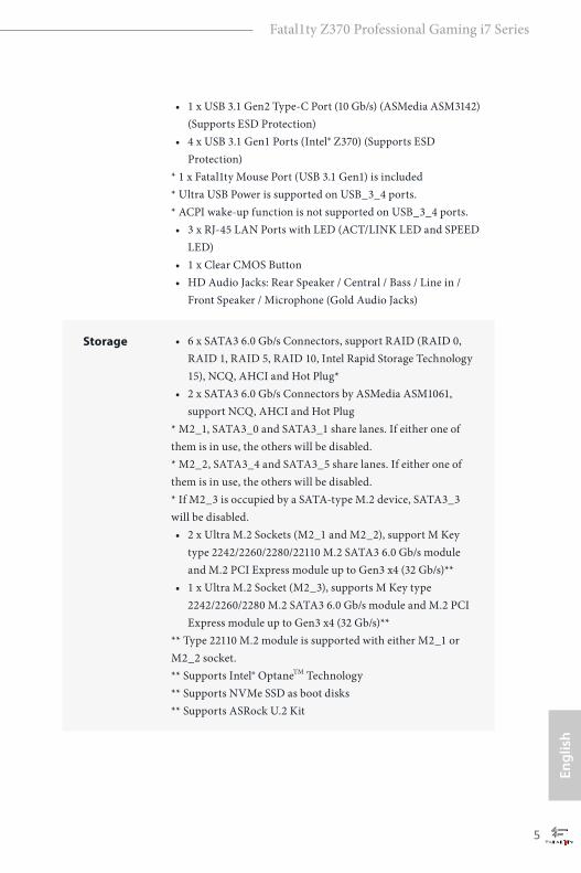
• 1 x USB 3.1 Gen2 Type-C Port (10 Gb/s) (ASMedia ASM3142) (Supports ESD Protection)
• 4 x USB 3.1 Gen1 Ports (Intel® Z370) (Supports ESD Protection)
* 1 x Fatal1ty Mouse Port (USB 3.1 Gen1) is included* Ultra USB Power is supported on USB_3_4 ports.* ACPI wake-up function is not supported on USB_3_4 ports.• 3 x RJ-45 LAN Ports with LED (ACT/LINK LED and SPEED
LED)• 1 x Clear CMOS Button• HD Audio Jacks: Rear Speaker / Central / Bass / Line in /
Front Speaker / Microphone (Gold Audio Jacks)
Storage • 6 x SATA3 6.0 Gb/s Connectors, support RAID (RAID 0, RAID 1, RAID 5, RAID 10, Intel Rapid Storage Technology 15), NCQ, AHCI and Hot Plug*
• 2 x SATA3 6.0 Gb/s Connectors by ASMedia ASM1061, support NCQ, AHCI and Hot Plug
* M2_1, SATA3_0 and SATA3_1 share lanes. If either one of them is in use, the others will be disabled. * M2_2, SATA3_4 and SATA3_5 share lanes. If either one of them is in use, the others will be disabled. * If M2_3 is occupied by a SATA-type M.2 device, SATA3_3 will be disabled.• 2 x Ultra M.2 Sockets (M2_1 and M2_2), support M Key
type 2242/2260/2280/22110 M.2 SATA3 6.0 Gb/s module and M.2 PCI Express module up to Gen3 x4 (32 Gb/s)**
• 1 x Ultra M.2 Socket (M2_3), supports M Key type 2242/2260/2280 M.2 SATA3 6.0 Gb/s module and M.2 PCI Express module up to Gen3 x4 (32 Gb/s)**
** Type 22110 M.2 module is supported with either M2_1 or M2_2 socket. ** Supports Intel® OptaneTM Technology ** Supports NVMe SSD as boot disks** Supports ASRock U.2 Kit

English
6
Connector • 1 x TPM Header• 1 x Power LED and Speaker Header• 1 x RGB LED Header
* Supports in total up to 12V/3A, 36W LED Strip• 1 x CPU Fan Connector (4-pin)
* The CPU Fan Connector supports the CPU fan of maximum 1A (12W) fan power. • 1 x CPU Optional/Water Pump Fan Connector (4-pin)
(Smart Fan Speed Control)* The CPU Optional/Water Pump Fan supports the water cooler fan of maximum 1.5A (18W) fan power. • 2 x Chassis Fan Connectors (4-pin) (Smart Fan Speed
Control)• 1 x Chassis Optional/Water Pump Fan Connector (4-pin)
(Smart Fan Speed Control)* The Chassis Optional/Water Pump Fan supports the water cooler fan of maximum 1.5A (18W) fan power. * CPU_OPT/W_PUMP, CHA_FAN1, CHA_FAN2 and CHA_FAN3/W_PUMP can auto detect if 3-pin or 4-pin fan is in use.• 1 x 24 pin ATX Power Connector (Hi-Density Power
Connector)• 1 x 8 pin 12V Power Connector (Hi-Density Power
Connector)• 1 x Front Panel Audio Connector (15μ Gold Audio
Connector)• 1 x Thunderbolt AIC Connector (5-pin)• 3 x USB 2.0 Headers (Support 6 USB 2.0 ports) (Intel® Z370)
(Supports ESD Protection)• 2 x USB 3.1 Gen1 Headers (Support 4 USB 3.1 Gen1 ports)
(ASMedia ASM1074 hub) (Supports ESD Protection)• 1 x Front Panel Type C USB 3.1 Gen2 Header (ASMedia
ASM3142)• 1 x Dr. Debug with LED• 1 x Power Button with LED• 1 x Reset Button with LED• 1 x XMP Switch• 1 x BIOS B Select Jumper

Engl
ish
Fatal1ty Z370 Professional Gaming i7 Series
7
BIOS Feature
• 2 x AMI UEFI Legal BIOS with multilingual GUI support (1 x Main BIOS and 1 x Backup BIOS)
• Supports Secure Backup UEFI Technology• ACPI 6.0 Compliant wake up events• SMBIOS 2.7 Support• CPU Core/Cache, GT Core/Cache, DRAM, PCH 1.0V,
VCCIO, VCCST, VCCSA, VCCPLL, CPU Internal PLL, GT PLL, Ring PLL, System Agent PLL, Memory Controller PLL Voltage Multi-adjustment
Hardware Monitor
• Temperature Sensing: CPU, CPU Optional/Water Pump, Chassis, Chassis Optional/Water Pump Fans
• Fan Tachometer: CPU, CPU Optional/Water Pump, Chassis, Chassis Optional/Water Pump Fans
• Quiet Fan (Auto adjust chassis fan speed by CPU tempera-ture): CPU, CPU Optional/Water Pump, Chassis, Chassis Optional/Water Pump Fans
• Fan Multi-Speed Control: CPU, CPU Optional/Water Pump, Chassis, Chassis Optional/Water Pump Fans
• Voltage monitoring: +12V, +5V, +3.3V, CPU Vcore, DRAM, VPPM, PCH 1.0V, VCCSA, VCCST
OS • Microsoft® Windows® 10 64-bit
Certifica-tions
• FCC, CE• ErP/EuP ready (ErP/EuP ready power supply is required)
* For detailed product information, please visit our website: http://www.asrock.com
Please realize that there is a certain risk involved with overclocking, including adjusting the setting in the BIOS, applying Untied Overclocking Technology, or using third-party overclocking tools. Overclocking may affect your system’s stability, or even cause damage to the components and devices of your system. It should be done at your own risk and expense. We are not responsible for possible damage caused by overclocking.
English
8
IntelZ370
DD
R4
_A
2 (
64 b
it, 2
88
-pin
mo
du
le)
DD
R4
_A
1 (
64 b
it, 2
88
-pin
mo
du
le)
DD
R4
_B
2 (
64 b
it, 2
88
-pin
mo
du
le)
DD
R4
_B
1 (
64 b
it, 2
88
-pin
mo
du
le)
ATX12V1
AT
XP
WR
1
PCIE2
Top:RJ-45(I211AT)
USB 3.1 Gen1T: USB3B: USB4
To
p:
Ce
ntra
l/Ba
ss
Ce
nte
r:R
EA
R S
PK
To
p:
LIN
E IN
Ce
nte
r:F
RO
NT
Bo
ttom
:O
ptic
al
SP
DIF
Bo
ttom
:M
IC IN
PCIE4
HDLED RESET
PLED PWRBTN
PANEL1
11
SPK_PLED1
1
HD_AUDIO1
PCIE5
PCIE1
7
8
1
20
1
22 2123
1
24 1928
CLRBTN1
1 54
27
17
US
B 3
.1 G
en
1T: U
SB
1B
: US
B2
PS
2K
ey
bo
ard
/Mo
us
e
CMOSBattery
T B1
1
26
2
US
B_
5_
6
1
18
CPU_FAN1
1TPMS1
USB 3.1 Gen2T: USB31_TA_1B: USB31_TC_1
3
1
US
B_
7_
8
25
CPU_OPT/W_PUMP
M2_WIFI_1
HD
MI_
1
DIS
PL
AY
I_1
RJ-45(I219V)
Dr.Debug
XM
P_
ON
1
BIOS_A1
BIOS_B1
BIOS_A_LED1
BIOSROM BIOS_B_LED1
BIOSROM
RGB_LED1
1
CHA_FAN2
CHA_FAN1
6
9
10
11
LAN
LAN
Ultra M.2PCIe Gen3 x4
RoHS
ON
OFF
FATAL TY1
RSTBTN1 PWRBTN1
2930
Top:RJ-45(AQC107)
F_USB31_TC_2
SA
TA
3_
2_
3S
AT
A3
_4
_5
SA
TA
3_
A1
_A
2
13
12
14
15
16
SA
TA
3_
0_
1
CHA_FAN3/W_PUMP
PCIE3
M2
_3
M2
_1
M2
_2
CLRMOS1
1
LAN
AUDIOCODEC
D_BIOS_TEST1
11
USB_13_14USB_11_12USB_9_10
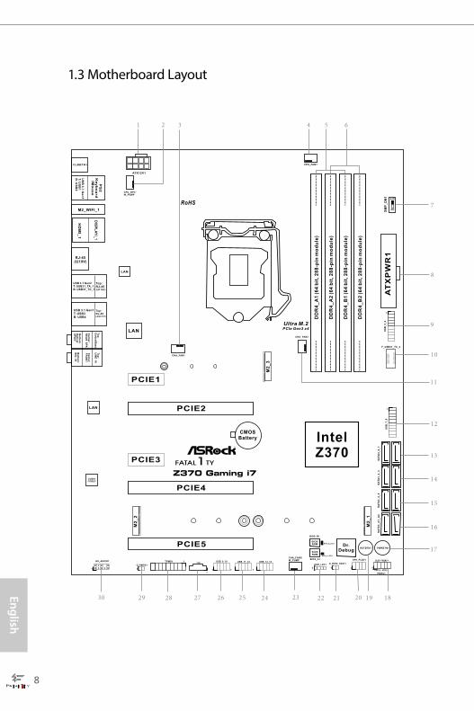
1.3 Motherboard Layout

Engl
ish
Fatal1ty Z370 Professional Gaming i7 Series
9
No. Description
1 ATX 12V Power Connector (ATX12V1)
2 CPU Fan / Waterpump Fan Connector (CPU_OPT/W_PUMP)
3 Chassis Fan Connector (CHA_FAN1)
4 CPU Fan Connector (CPU_FAN1)
5 2 x 288-pin DDR4 DIMM Slots (DDR4_A1, DDR4_B1)
6 2 x 288-pin DDR4 DIMM Slots (DDR4_A2, DDR4_B2)
7 XMP Button (XMP_ON1)
8 ATX Power Connector (ATXPWR1)
9 USB 3.1 Gen1 Header (USB_5_6)
10 Front Panel Type C USB 3.1 Gen2 Header (F_USB31_TC_2)
11 Chassis Fan Connector (CHA_FAN2)
12 USB 3.1 Gen1 Header (USB_7_8)
13 SATA3 Connectors (SATA3_0_1)
14 SATA3 Connectors (SATA3_2_3)
15 SATA3 Connectors (SATA3_4_5)
16 SATA3 Connectors (SATA3_A1_A2)
17 Power Button (PWRBTN1)
18 System Panel Header (PANEL1)
19 Reset Button (RSTBTN1)
20 Power LED and Speaker Header (SPK_PLED1)
21 BIOS B Select Jumper (D_BIOS_TEST1)
22 RGB LED Header (RGB_LED1)
23 Chassis Fan / Waterpump Fan Connector (CHA_FAN3/W_PUMP)
24 USB 2.0 Header (USB_13_14)
25 USB 2.0 Header (USB_11_12)
26 USB 2.0 Header (USB_9_10)
27 Thunderbolt AIC Header (TB1)
28 TPM Header (TPMS1)
29 Clear CMOS Jumper (CLRMOS1)
30 Front Panel Audio Header (HD_AUDIO1)

English
10
1.4 I/O Panel
No. Description No. Description
1 PS/2 Mouse/Keyboard Port 11 USB 3.1 Gen1 Ports (USB_3_4) ****
2 DisplayPort 1.2 12 USB 3.1 Gen2 Type-A Port (USB31_TA_1)
3 LAN RJ-45 Port (Intel® I211AT)* 13 USB 3.1 Gen2 Type-C Port (USB31_TC_1)
4GLAN RJ-45 Port (AQUANTIA® AQC107)**
14 LAN RJ-45 Port (Intel® I219V)*
5 Central / Bass (Orange) 15 HDMI Port
6 Rear Speaker (Black) 16 Antenna Ports
7 Line In (Light Blue) 17 Fatal1ty Mouse Port (USB_1)
8 Front Speaker (Lime)*** 18 USB 3.1 Gen1 Port (USB_2)
9 Microphone (Pink) 19 Clear CMOS Button
10 Optical SPDIF Out Port
* There are two LEDs on each LAN port. Please refer to the table below for the LAN port LED indications.
Activity / Link LED Speed LED
Status Description Status DescriptionOff No Link Off 10Mbps connectionBlinking Data Activity Orange 100Mbps connectionOn Link Green 1Gbps connection
ACT/LINK LED
SPEED LED
LAN Port
1
91012
13
17 11141519
2 65
87
3
16
18
4

Engl
ish
Fatal1ty Z370 Professional Gaming i7 Series
11
** There are two LEDs on each LAN port. Please refer to the table below for the LAN port LED indications.
Activity / Link LED Speed LED
Status Description Status DescriptionOff No Link Orange 100Mbps/1Gbps/2.5Gbps
/5Gbps connectionBlinking Data ActivityOn Link Green 10Gbps connection
*** If you use a 2-channel speaker, please connect the speaker’s plug into “Front Speaker Jack”. See the table below for connection details in accordance with the type of speaker you use.
Audio Output Channels
Front Speaker(No. 8)
Rear Speaker(No. 6)
Central / Bass(No. 5)
Line In(No. 7)
2 V -- -- --4 V V -- --6 V V V --8 V V V V
**** ACPI wake-up function is not supported on USB_3_4 ports.
To enable Multi-Streaming, you need to connect a front panel audio cable to the front panel audio header. After restarting your computer, you will find the “Mixer” tool on your system. Please select “Mixer ToolBox” , click “Enable playback multi-streaming”, and click “ok”. Choose “2CH”, “4CH”, “6CH”, or “8CH” and then you are allowed to select “Realtek HDA Primary output” to use the Rear Speaker, Central/Bass, and Front Speaker, or select “Realtek HDA Audio 2nd output” to use the front panel audio.
ACT/LINK LED
SPEED LED
LAN Port

English
12
1.5 WiFi-802.11ac Module and ASRock WiFi 2.4/5 GHz Antenna
WiFi-802.11ac + BT ModuleThis motherboard comes with an exclusive WiFi 802.11 a/b/g/n/ac + BT v4.2 module (pre-installed on the rear I/O panel) that offers support for WiFi 802.11 a/b/g/n/ac connectivity standards and Bluetooth v4.2. WiFi + BT module is an easy-to-use wireless local area network (WLAN) adapter to support WiFi + BT. Bluetooth v4.2 standard features Smart Ready technology that adds a whole new class of functionality into the mobile devices. BT 4.2 also includes Low Energy Technology and ensures extraordinary low power consumption for PCs.
* The transmission speed may vary according to the environment.
Engl
ish
Fatal1ty Z370 Professional Gaming i7 Series
13
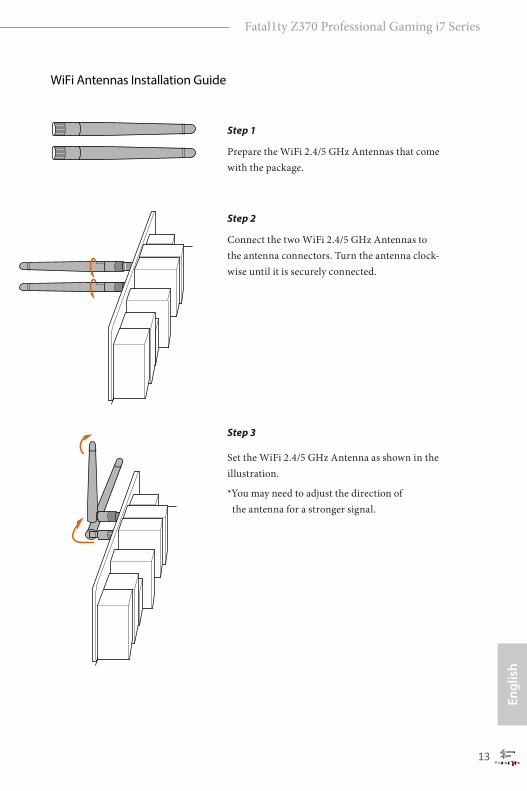
WiFi Antennas Installation Guide
Step 1
Prepare the WiFi 2.4/5 GHz Antennas that come with the package.
Step 2
Connect the two WiFi 2.4/5 GHz Antennas to the antenna connectors. Turn the antenna clock-wise until it is securely connected.
Step 3
Set the WiFi 2.4/5 GHz Antenna as shown in the illustration.
*You may need to adjust the direction of the antenna for a stronger signal.

English
14
This is an ATX form factor motherboard. Before you install the motherboard, study the configuration of your chassis to ensure that the motherboard fits into it.
Pre-installation PrecautionsTake note of the following precautions before you install motherboard components or change any motherboard settings.
• Make sure to unplug the power cord before installing or removing the motherboard components. Failure to do so may cause physical injuries and damages to motherboard components.
• In order to avoid damage from static electricity to the motherboard’s components, NEVER place your motherboard directly on a carpet. Also remember to use a grounded wrist strap or touch a safety grounded object before you handle the components.
• Hold components by the edges and do not touch the ICs.• Whenever you uninstall any components, place them on a grounded anti-static pad or
in the bag that comes with the components.• When placing screws to secure the motherboard to the chassis, please do not over-
tighten the screws! Doing so may damage the motherboard.
Chapter 2 Installation

Engl
ish
Fatal1ty Z370 Professional Gaming i7 Series
15
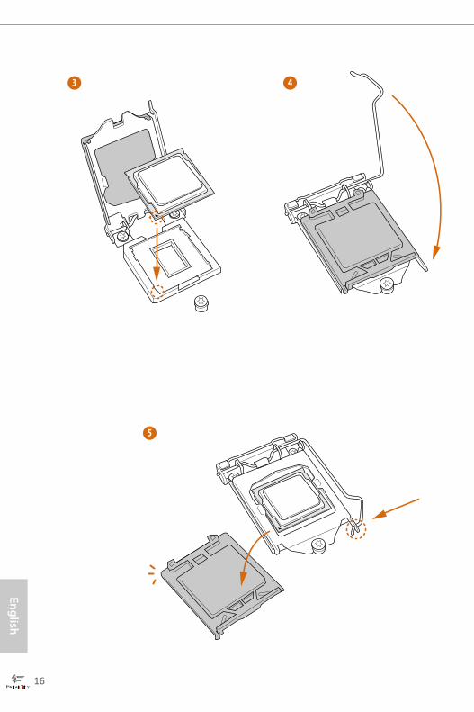
2.1 Installing the CPU
1. Before you insert the 1151-Pin CPU into the socket, please check if the PnP cap is on the socket, if the CPU surface is unclean, or if there are any bent pins in the socket. Do not force to insert the CPU into the socket if above situation is found. Otherwise, the CPU will be seriously damaged.
2. Unplug all power cables before installing the CPU.
1
2
A
B
English
16
4
5
3

Engl
ish
Fatal1ty Z370 Professional Gaming i7 Series
17
Please save and replace the cover if the processor is removed. The cover must be placed if you wish to return the motherboard for after service.
English
18
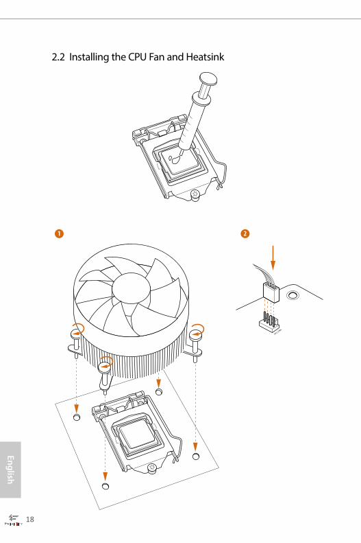
2.2 Installing the CPU Fan and Heatsink
1 2
CPU_FAN
Engl
ish
Fatal1ty Z370 Professional Gaming i7 Series
19
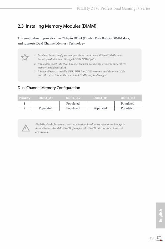
2.3 Installing Memory Modules (DIMM)
This motherboard provides four 288-pin DDR4 (Double Data Rate 4) DIMM slots, and supports Dual Channel Memory Technology.
Dual Channel Memory Configuration
The DIMM only fits in one correct orientation. It will cause permanent damage to the motherboard and the DIMM if you force the DIMM into the slot at incorrect orientation.
Priority DDR4_A1 DDR4_A2 DDR4_B1 DDR4_B2
1 Populated Populated 2 Populated Populated Populated Populated
1. For dual channel configuration, you always need to install identical (the same brand, speed, size and chip-type) DDR4 DIMM pairs.
2. It is unable to activate Dual Channel Memory Technology with only one or three memory module installed.
3. It is not allowed to install a DDR, DDR2 or DDR3 memory module into a DDR4 slot; otherwise, this motherboard and DIMM may be damaged.

English
20
1
2
3
Engl
ish
Fatal1ty Z370 Professional Gaming i7 Series
21
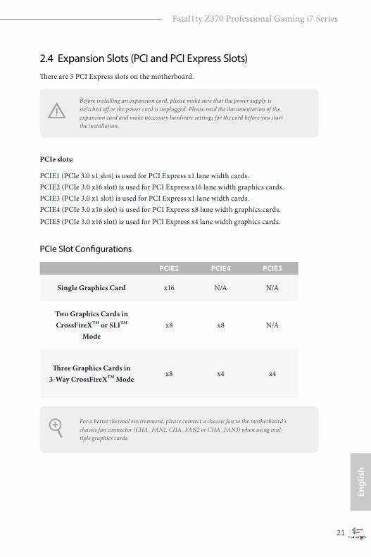
2.4 Expansion Slots (PCI and PCI Express Slots)There are 5 PCI Express slots on the motherboard.
PCIe slots:
PCIE1 (PCIe 3.0 x1 slot) is used for PCI Express x1 lane width cards. PCIE2 (PCIe 3.0 x16 slot) is used for PCI Express x16 lane width graphics cards. PCIE3 (PCIe 3.0 x1 slot) is used for PCI Express x1 lane width cards. PCIE4 (PCIe 3.0 x16 slot) is used for PCI Express x8 lane width graphics cards. PCIE5 (PCIe 3.0 x16 slot) is used for PCI Express x4 lane width graphics cards.
PCIe Slot Configurations
For a better thermal environment, please connect a chassis fan to the motherboard’s chassis fan connector (CHA_FAN1, CHA_FAN2 or CHA_FAN3) when using mul-tiple graphics cards.
Before installing an expansion card, please make sure that the power supply is switched off or the power cord is unplugged. Please read the documentation of the expansion card and make necessary hardware settings for the card before you start the installation.
PCIE2 PCIE4 PCIE5
Single Graphics Card x16 N/A N/A
Two Graphics Cards in CrossFireXTM or SLITM
Modex8 x8 N/A
Three Graphics Cards in 3-Way CrossFireXTM Mode
x8 x4 x4

English
22
The Clear CMOS Button has the same function as the Clear CMOS jumper.
2.5 Jumpers SetupThe illustration shows how jumpers are setup. When the jumper cap is placed on the pins, the jumper is “Short”. If no jumper cap is placed on the pins, the jumper is “Open”.
Clear CMOS Jumper(CLRCMOS1)(see p.8, No. 29)
Short: Clear CMOS Open: Default
CLRCMOS1 allows you to clear the data in CMOS. The data in CMOS includes system setup information such as system password, date, time, and system setup parameters. To clear and reset the system parameters to default setup, please turn off the computer and unplug the power cord, then use a jumper cap to short the pins on CLRCMOS1 for 3 seconds. Please remember to remove the jumper cap after clearing the CMOS. If you need to clear the CMOS when you just finish updating the BIOS, you must boot up the system first, and then shut it down before you do the clear-CMOS action.
2-pin Jumper

Engl
ish
Fatal1ty Z370 Professional Gaming i7 Series
23
2.6 Onboard Headers and Connectors
System Panel Header(9-pin PANEL1)(see p.8, No. 18)
Connect the power button, reset button and system status indicator on the chassis to this header according to the pin assignments below. Note the positive and negative pins before connecting the cables.
GND
RESET#
PWRBTN#
PLED-
PLED+
GND
HDLED-
HDLED+
1
GND
Onboard headers and connectors are NOT jumpers. Do NOT place jumper caps over these headers and connectors. Placing jumper caps over the headers and connectors will cause permanent damage to the motherboard.
PWRBTN (Power Button): Connect to the power button on the chassis front panel. You may configure the way to turn off your system using the power button.
RESET (Reset Button): Connect to the reset button on the chassis front panel. Press the reset button to restart the computer if the computer freezes and fails to perform a normal restart.
PLED (System Power LED): Connect to the power status indicator on the chassis front panel. The LED is on when the system is operating. The LED keeps blinking when the system is in S1/S3 sleep state. The LED is off when the system is in S4 sleep state or powered off (S5).
HDLED (Hard Drive Activity LED): Connect to the hard drive activity LED on the chassis front panel. The LED is on when the hard drive is reading or writing data.
The front panel design may differ by chassis. A front panel module mainly consists of power button, reset button, power LED, hard drive activity LED, speaker and etc. When connect-ing your chassis front panel module to this header, make sure the wire assignments and the pin assignments are matched correctly.
English
24
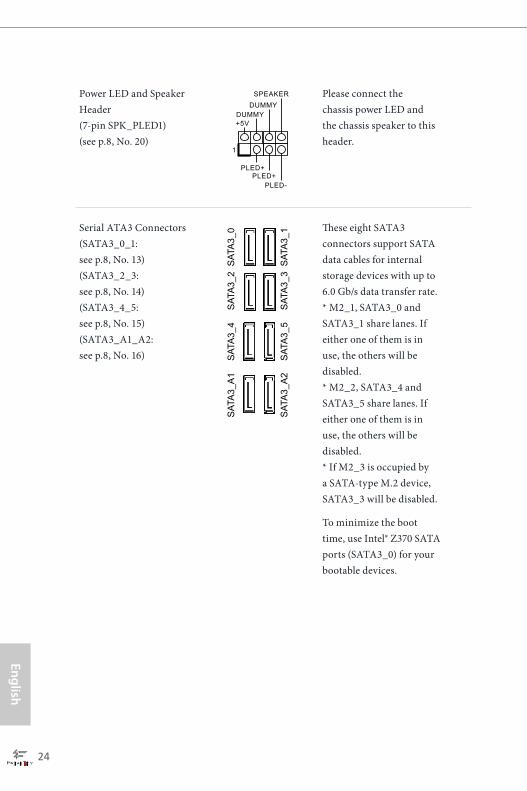
Power LED and Speaker Header(7-pin SPK_PLED1)(see p.8, No. 20)
Please connect the chassis power LED and the chassis speaker to this header.
Serial ATA3 Connectors(SATA3_0_1: see p.8, No. 13)(SATA3_2_3: see p.8, No. 14)(SATA3_4_5: see p.8, No. 15)(SATA3_A1_A2: see p.8, No. 16)
These eight SATA3 connectors support SATA data cables for internal storage devices with up to 6.0 Gb/s data transfer rate. * M2_1, SATA3_0 and SATA3_1 share lanes. If either one of them is in use, the others will be disabled. * M2_2, SATA3_4 and SATA3_5 share lanes. If either one of them is in use, the others will be disabled. * If M2_3 is occupied by a SATA-type M.2 device, SATA3_3 will be disabled.
To minimize the boot time, use Intel® Z370 SATA ports (SATA3_0) for your bootable devices.
1
+5VDUMMY
PLED+PLED+
PLED-
DUMMYSPEAKER
SAT
A3_
A1
SAT
A3_
4
SAT
A3_
5S
ATA
3_A
2
SAT
A3_
0S
ATA
3_2
SAT
A3_
1S
ATA
3_3
Engl
ish
Fatal1ty Z370 Professional Gaming i7 Series
25
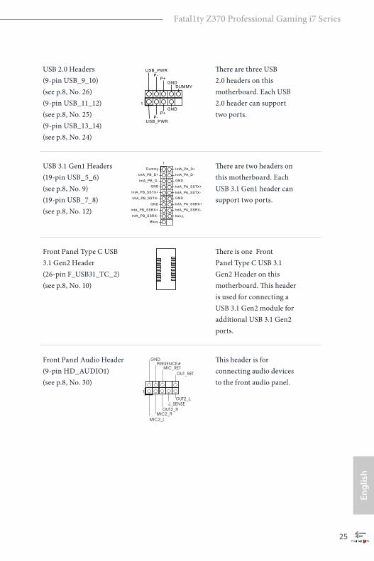
USB 2.0 Headers(9-pin USB_9_10)(see p.8, No. 26) (9-pin USB_11_12)(see p.8, No. 25)(9-pin USB_13_14)(see p.8, No. 24)
There are three USB 2.0 headers on this motherboard. Each USB 2.0 header can support two ports.
USB 3.1 Gen1 Headers(19-pin USB_5_6)(see p.8, No. 9) (19-pin USB_7_8)(see p.8, No. 12)
There are two headers on this motherboard. Each USB 3.1 Gen1 header can support two ports.
Front Panel Type C USB 3.1 Gen2 Header(26-pin F_USB31_TC_2)(see p.8, No. 10)
There is one Front Panel Type C USB 3.1 Gen2 Header on this motherboard. This header is used for connecting a USB 3.1 Gen2 module for additional USB 3.1 Gen2 ports.
Front Panel Audio Header(9-pin HD_AUDIO1)(see p.8, No. 30)
This header is for connecting audio devices to the front audio panel.
1
IntA_PB_D+
Dummy
IntA_PB_D-
GND
IntA_PB_SSTX+
GND
IntA_PB_SSTX-
IntA_PB_SSRX+
IntA_PB_SSRX-
VbusV
Vbus
IntA_PA_SSRX-
IntA_PA_SSRX+
GND
IntA_PA_SSTX-
IntA_PA_SSTX+
GND
IntA_PA_D-
IntA_PA_D+
DUMMYGND
GND
P+P-
USB_PWR
P+P-
USB_PWR
1
J_SENSE
OUT2_L
1
MIC_RETPRESENCE#
GND
OUT2_RMIC2_R
MIC2_L
OUT_RET

English
26
Chassis Fan / Waterpump Fan Connector(4-pin CHA_FAN3/W_PUMP)(see p.8, No. 23)
Please connect fan cables to the fan connectors and match the black wire to the ground pin.
Chassis Fan Connector(4-pin CHA_FAN1)(see p.8, No. 3)
(4-pin CHA_FAN2)(see p.8, No. 11)
Please connect fan cables to the fan connectors and match the black wire to the ground pin.
CPU Fan Connector(4-pin CPU_FAN1)(see p.8, No. 4)
This motherboard provides a 4-Pin CPU fan (Quiet Fan) connector. If you plan to connect a 3-Pin CPU fan, please connect it to Pin 1-3.
1. High Definition Audio supports Jack Sensing, but the panel wire on the chassis must support HDA to function correctly. Please follow the instructions in our manual and chassis manual to install your system.
2. If you use an AC’97 audio panel, please install it to the front panel audio header by the steps below: A. Connect Mic_IN (MIC) to MIC2_L. B. Connect Audio_R (RIN) to OUT2_R and Audio_L (LIN) to OUT2_L. C. Connect Ground (GND) to Ground (GND). D. MIC_RET and OUT_RET are for the HD audio panel only. You don’t need to connect them for the AC’97 audio panel. E. To activate the front mic, go to the “FrontMic” Tab in the Realtek Control panel and adjust “Recording Volume”.
GND
FAN_SPEED
FAN_SPEED_CONTROL
FAN_VOLTAGE
1 2 3 4
GNDFAN_VOLTAGE
CHA_FAN_SPEEDFAN_SPEED_CONTROL 4
321
GND
FAN_VOLTAGECHA_FAN_SPEED
FAN_SPEED_CONTROL
4 3 2 1
FAN_VOLTAGEGND
CPU_FAN_SPEED
FAN_SPEED_CONTROL
1 2 3 4
Engl
ish
Fatal1ty Z370 Professional Gaming i7 Series
27
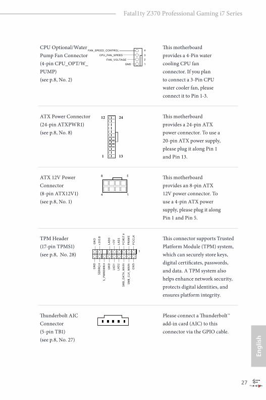
CPU Optional/Water Pump Fan Connector (4-pin CPU_OPT/W_PUMP)(see p.8, No. 2)
This motherboard provides a 4-Pin water cooling CPU fan connector. If you plan to connect a 3-Pin CPU water cooler fan, please connect it to Pin 1-3.
ATX Power Connector(24-pin ATXPWR1)(see p.8, No. 8)
This motherboard provides a 24-pin ATX power connector. To use a 20-pin ATX power supply, please plug it along Pin 1 and Pin 13.
ATX 12V Power Connector(8-pin ATX12V1)(see p.8, No. 1)
This motherboard provides an 8-pin ATX 12V power connector. To use a 4-pin ATX power supply, please plug it along Pin 1 and Pin 5.
TPM Header(17-pin TPMS1)(see p.8, No. 28)
This connector supports Trusted Platform Module (TPM) system, which can securely store keys, digital certificates, passwords, and data. A TPM system also helps enhance network security, protects digital identities, and ensures platform integrity.
Thunderbolt AIC Connector(5-pin TB1)(see p.8, No. 27)
Please connect a Thunderbolt™ add-in card (AIC) to this connector via the GPIO cable.
1
GND
SMB_
DATA
_MAIN
LAD2
LAD1
GND
S_PW
RDWN#
SERIRQ
#
GND
PCICLK
PCIRST
#
LAD3
+3V
LAD0
+3V
SB
GND
FRAME
SMB_
CLK
_MAIN
FAN_VOLTAGE
GND
CPU_FAN_SPEED
FAN_SPEED_CONTROL 4
3
2
1
12
1
24
13
1
4 1
8 5

English
28
RGB LED Header(4-pin RGB_LED1)(see p.8, No. 22)
RGB header is used to connect RGB LED extension cable which allows users to choose from various LED lighting effects.Caution: Never install the RGB LED cable in the wrong orientation; otherwise, the cable may be damaged.*Please refer to page 58 for further instructions on this header.
12V G R B1
Engl
ish
Fatal1ty Z370 Professional Gaming i7 Series
29
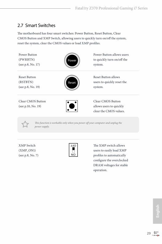
2.7 Smart SwitchesThe motherboard has four smart switches: Power Button, Reset Button, Clear CMOS Button and XMP Switch, allowing users to quickly turn on/off the system, reset the system, clear the CMOS values or load XMP profiles.
Power Button(PWRBTN)(see p.8, No. 17)
Power Button allows users to quickly turn on/off the system.
Reset Button(RSTBTN)(see p.8, No. 19)
Reset Button allows users to quickly reset the system.
Clear CMOS Button(see p.10, No. 19)
Clear CMOS Button allows users to quickly clear the CMOS values.
XMP Switch(XMP_ON1)(see p.8, No. 7)
The XMP switch allows users to easily load XMP profiles to automatically configure the overclocked DRAM voltages for stable operation.
This function is workable only when you power off your computer and unplug the power supply.
Power
Reset
ON
OFF

English
30
2.8 Dr. DebugDr. Debug is used to provide code information, which makes troubleshooting even easier. Please see the diagrams below for reading the Dr. Debug codes.
Code Description
00 Please check if the CPU is installed correctly and then clear CMOS.
0d Problem related to memory, VGA card or other devices. Please clear CMOS, re-install the memory and VGA card, and remove other USB, PCI devices.
01 - 54 (except 0d), 5A- 60
Problem related to memory. Please re-install the CPU andmemory then clear CMOS. If the problem still exists, please install only one memory module or try using other memory modules.
55 The Memory could not be detected. Please re-install the memory and CPU. If the problem still exists, please install only one memory module or try using other memory modules.
61 - 91 Chipset initialization error. Please press reset or clear CMOS.
92 - 99 Problem related to PCI-E devices. Please re-install PCI-E devices or try installing them in other slots. If the problem still exists, please remove all PCI-E devices or try using another VGA card.
A0 - A7 Problem related to IDE or SATA devices. Please re-install IDE and SATA devices. If the problem still exists, please clear CMOS and try removing all SATA devices.
b0 Problem related to memory. Please re-install the CPU and memory. If the problem still exists, please install only one memory module or try using other memory modules.
Engl
ish
Fatal1ty Z370 Professional Gaming i7 Series
31
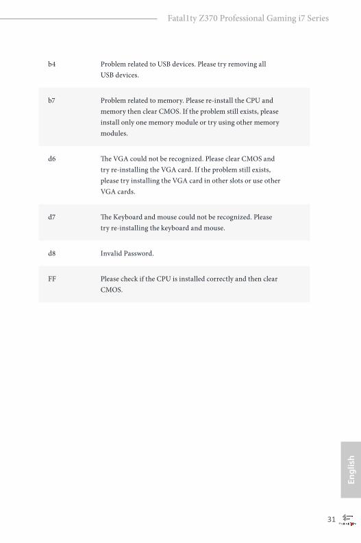
b4 Problem related to USB devices. Please try removing all USB devices.
b7 Problem related to memory. Please re-install the CPU and memory then clear CMOS. If the problem still exists, please install only one memory module or try using other memory modules.
d6 The VGA could not be recognized. Please clear CMOS and try re-installing the VGA card. If the problem still exists, please try installing the VGA card in other slots or use other VGA cards.
d7 The Keyboard and mouse could not be recognized. Please try re-installing the keyboard and mouse.
d8 Invalid Password.
FF Please check if the CPU is installed correctly and then clear CMOS.

English
32
2.9 SLITM and Quad SLITM Operation GuideThis motherboard supports NVIDIA® SLITM and Quad SLITM (Scalable Link Interface) technology that allows you to install up to two identical PCI Express x16 graphics cards.
2.9.1 Installing Two SLITM-Ready Graphics Cards
Step 1
Insert one graphics card into PCIE2 slot and the other graphics card to PCIE4 slot. Make sure that the cards are properly seated on the slots.
Step 2
If required, connect the auxiliary power source to the PCI Express graphics cards.
Requirements
1. You should only use identical SLITM-ready graphics cards that are NVIDIA® certified.2. Make sure that your graphics card driver supports NVIDIA® SLITM technology. Download
the drivers from the NVIDIA® website: www.nvidia.com3. Make sure that your power supply unit (PSU) can provide at least the minimum power
your system requires. It is recommended to use a NVIDIA® certified PSU. Please refer to the NVIDIA® website for details.

Engl
ish
Fatal1ty Z370 Professional Gaming i7 Series
33
Step 3
Align and insert the ASRock SLI_HB_Bridge_2S Card to the goldfingers on each graphics card. Make sure the ASRock SLI_HB_Bridge_2S Card is firmly in place.
Step 4
Connect a VGA cable or a DVI cable to the monitor connector or the DVI connector of the graphics card that is inserted to PCIE2 slot.
ASRock SLI_HB_Bridge_2S Card
SLI_HB_Bridge_2S Card
English
34
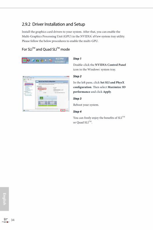
2.9.2 Driver Installation and SetupInstall the graphics card drivers to your system. After that, you can enable the Multi-Graphics Processing Unit (GPU) in the NVIDIA® nView system tray utility. Please follow the below procedures to enable the multi-GPU.
For SLITM and Quad SLITM mode
Step 1
Double-click the NVIDIA Control Panel icon in the Windows® system tray.
Step 2
In the left pane, click Set SLI and PhysX configuration. Then select Maximize 3D performance and click Apply.
Step 3
Reboot your system.
Step 4
You can freely enjoy the benefits of SLITM or Quad SLITM.

Engl
ish
Fatal1ty Z370 Professional Gaming i7 Series
35
2.10 CrossFireXTM , 3-Way CrossFireXTM and Quad CrossFireXTM Operation GuideThis motherboard supports CrossFireXTM, 3-way CrossFireXTM and Quad CrossFireXTM that allows you to install up to three identical PCI Express x16 graphics cards.
2.10.1 Installing Two CrossFireXTM-Ready Graphics Cards
Step 1
Insert one graphics card into PCIE2 slot and the other graphics card to PCIE4 slot. Make sure that the cards are properly seated on the slots.
Step 2
Connect two graphics cards by installing a CrossFire Bridge on the CrossFire Bridge Interconnects on the top of the graphics cards. (The CrossFire Bridge is provided with the graphics card you purchase, not bundled with this motherboard. Please refer to your graphics card vendor for details.)
1. You should only use identical CrossFireXTM-ready graphics cards that are AMD certified.2. Make sure that your graphics card driver supports AMD CrossFireXTM technology.
Download the drivers from the AMD’s website: www.amd.com3. Make sure that your power supply unit (PSU) can provide at least the minimum power
your system requires. It is recommended to use a AMD certified PSU. Please refer to the AMD’s website for details.
4. If you pair a 12-pipe CrossFireXTM Edition card with a 16-pipe card, both cards will oper-ate as 12-pipe cards while in CrossFireXTM mode.
5. Different CrossFireXTM cards may require different methods to enable CrossFireXTM. Please refer to AMD graphics card manuals for detailed installation guide.
CrossFire Bridge

English
36
Step 3
Connect a VGA cable or a DVI cable to the monitor connector or the DVI connec-tor of the graphics card that is inserted to PCIE2 slot.

Engl
ish
Fatal1ty Z370 Professional Gaming i7 Series
37
2.10.2 Installing Three CrossFireXTM-Ready Graphics Cards
Step 1
Insert one graphics card into PCIE2 slot, another graphics card to PCIE4 slot, and the other graphics card to PCIE5 slot. Make sure that the cards are properly seated on the slots.
Step 2
Use one CrossFire Bridge to connect the graphics cards on PCIE2 and PCIE4 slots, and use the other CrossFire Bridge to connect the graphics cards on PCIE4 and PCIE5 slots. (The CrossFire Bridge is provided with the graphics card you purchase, not bundled with this motherboard. Please refer to your graphics card vendor for details.)
Step 3
Connect a VGA cable or a DVI cable to the monitor connector or the DVI connec-tor of the graphics card that is inserted to PCIE2 slot.
CrossFire Bridge
English
38
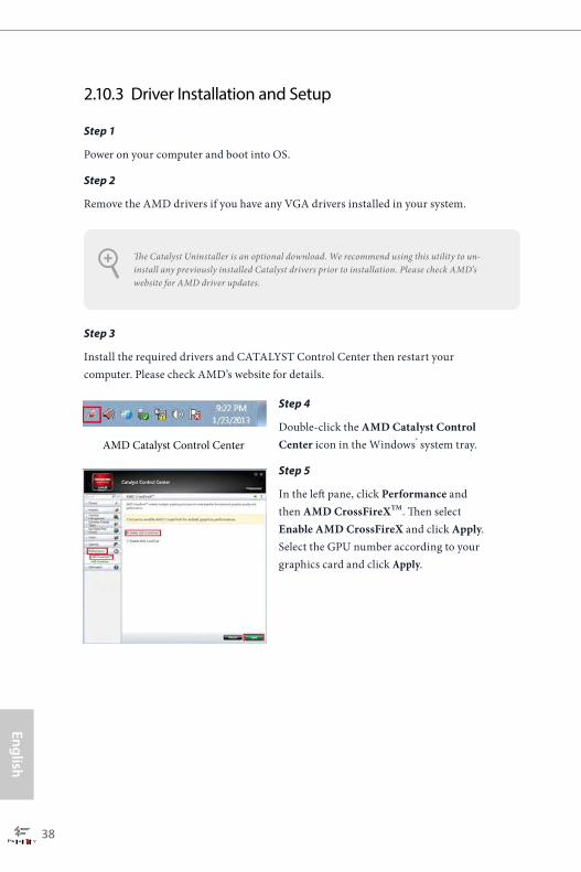
Step 1
Power on your computer and boot into OS.
Step 2
Remove the AMD drivers if you have any VGA drivers installed in your system.
Step 3
Install the required drivers and CATALYST Control Center then restart your computer. Please check AMD’s website for details.
2.10.3 Driver Installation and Setup
Step 4
Double-click the AMD Catalyst Control Center icon in the Windows® system tray.
Step 5
In the left pane, click Performance and then AMD CrossFireXTM. Then select Enable AMD CrossFireX and click Apply.Select the GPU number according to your graphics card and click Apply.
AMD Catalyst Control Center
The Catalyst Uninstaller is an optional download. We recommend using this utility to un-install any previously installed Catalyst drivers prior to installation. Please check AMD’s website for AMD driver updates.
Engl
ish
Fatal1ty Z370 Professional Gaming i7 Series
39
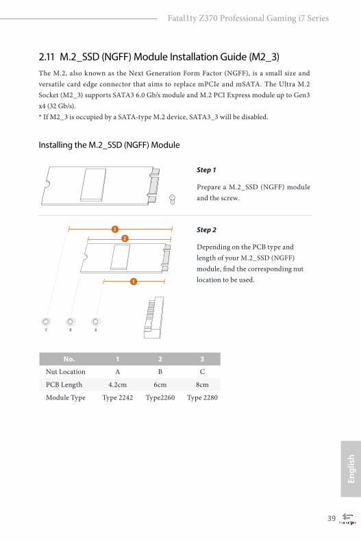
2.11 M.2_SSD (NGFF) Module Installation Guide (M2_3)The M.2, also known as the Next Generation Form Factor (NGFF), is a small size and versatile card edge connector that aims to replace mPCIe and mSATA. The Ultra M.2 Socket (M2_3) supports SATA3 6.0 Gb/s module and M.2 PCI Express module up to Gen3 x4 (32 Gb/s). * If M2_3 is occupied by a SATA-type M.2 device, SATA3_3 will be disabled.
Installing the M.2_SSD (NGFF) Module
Step 1
Prepare a M.2_SSD (NGFF) module and the screw.
2
1
3
ABC
Step 2
Depending on the PCB type and length of your M.2_SSD (NGFF) module, find the corresponding nut location to be used.
No. 1 2 3
Nut Location A B C
PCB Length 4.2cm 6cm 8cm
Module Type Type 2242 Type2260 Type 2280
English
40
ABC
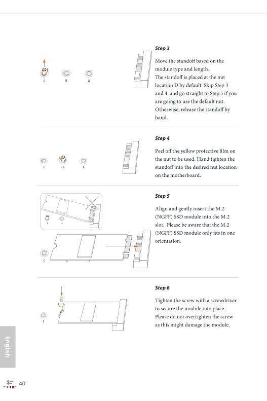
Step 3
Move the standoff based on the module type and length. The standoff is placed at the nut location D by default. Skip Step 3 and 4 and go straight to Step 5 if you are going to use the default nut. Otherwise, release the standoff by hand.
ABC
Step 4
Peel off the yellow protective film on the nut to be used. Hand tighten the standoff into the desired nut location on the motherboard.
AB
ABC
Step 5
Align and gently insert the M.2 (NGFF) SSD module into the M.2 slot. Please be aware that the M.2 (NGFF) SSD module only fits in one orientation.
NUT1NUT2C
Step 6
Tighten the screw with a screwdriver to secure the module into place. Please do not overtighten the screw as this might damage the module.

Engl
ish
Fatal1ty Z370 Professional Gaming i7 Series
41
M.2_SSD (NGFF) Module Support List
Vendor Interface P/NADATA SATA3 AXNS381E-128GM-BADATA SATA3 AXNS381E-256GM-BADATA SATA3 ASU800NS38-256GT-CADATA SATA3 ASU800NS38-512GT-CADATA PCIe3 x4 ASX7000NP-128GT-CADATA PCIe3 x4 ASX8000NP-256GM-CADATA PCIe3 x4 ASX7000NP-256GT-CADATA PCIe3 x4 ASX8000NP-512GM-CADATA PCIe3 x4 ASX7000NP-512GT-CApacer PCIe3 x4 AP240GZ280Corsair PCIe3 x4 CSSD-F240GBMP500Crucial SATA3 CT120M500SSD4Crucial SATA3 CT240M500SSD4Intel SATA3 Intel SSDSCKGW080A401/80GIntel PCIe3 x4 SSDPEKKF256G7Intel PCIe3 x4 SSDPEKKF512G7Kingston SATA3 SM2280S3Kingston PCIe3 x4 SKC1000/480GKingston PCIe2 x4 SH2280S3/480GOCZ PCIe3 x4 RVD400 -M2280-512G (NVME)PATRIOT PCIe3 x4 PH240GPM280SSDR NVMEPlextor PCIe3 x4 PX-128M8PeGPlextor PCIe3 x4 PX-1TM8PeGPlextor PCIe3 x4 PX-256M8PeGPlextor PCIe3 x4 PX-512M8PeGPlextor PCIe PX-G256M6ePlextor PCIe PX-G512M6eSamsung PCIe3 x4 SM961 MZVPW128HEGM (NVM)Samsung PCIe3 x4 PM961 MZVLW128HEGR (NVME)Samsung PCIe3 x4 960 EVO (MZ-V6E250) (NVME)Samsung PCIe3 x4 960 EVO (MZ-V6E250BW) (NVME)Samsung PCIe3 x4 SM951 (NVME)Samsung PCIe3 x4 SM951 (MZHPV256HDGL)Samsung PCIe3 x4 SM951 (MZHPV512HDGL)Samsung PCIe3 x4 SM951 (NVME)Samsung PCIe x4 XP941-512G (MZHPU512HCGL)SanDisk PCIe SD6PP4M-128GSanDisk PCIe SD6PP4M-256GTeam SATA3 TM4PS4128GMC105Team SATA3 TM4PS4256GMC105Team SATA3 TM8PS4128GMC105Team SATA3 TM8PS4256GMC105TEAM PCIe3 x4 TM8FP2240G0C101
English
42
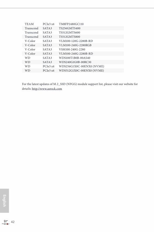
For the latest updates of M.2_SSD (NFGG) module support list, please visit our website for details: http://www.asrock.com
TEAM PCIe3 x4 TM8FP2480GC110Transcend SATA3 TS256GMTS400Transcend SATA3 TS512GMTS600Transcend SATA3 TS512GMTS800V-Color SATA3 VLM100-120G-2280B-RDV-Color SATA3 VLM100-240G-2280RGBV-Color SATA3 VSM100-240G-2280V-Color SATA3 VLM100-240G-2280B-RDWD SATA3 WDS100T1B0B-00AS40WD SATA3 WDS240G1G0B-00RC30WD PCIe3 x4 WDS256G1X0C-00ENX0 (NVME)WD PCIe3 x4 WDS512G1X0C-00ENX0 (NVME)
Engl
ish
Fatal1ty Z370 Professional Gaming i7 Series
43
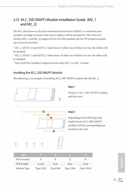
2.12 M.2_SSD (NGFF) Module Installation Guide (M2_1 and M2_2)
The M.2, also known as the Next Generation Form Factor (NGFF), is a small size and versatile card edge connector that aims to replace mPCIe and mSATA. The Ultra M.2 Sockets (M2_1 and M2_2) support SATA3 6.0 Gb/s module and M.2 PCI Express module up to Gen3 x4 (32 Gb/s).
* M2_1, SATA3_0 and SATA3_1 share lanes. If either one of them is in use, the others will be disabled. * M2_2, SATA3_4 and SATA3_5 share lanes. If either one of them is in use, the others will be disabled. * Type 22110 M.2 module is supported with either M2_1 or M2_2 socket.
Installing the M.2_SSD (NGFF) Module
The following is an example of installing M.2_SSD (NGFF) module into the M2_2.
Step 1
Prepare a M.2_SSD (NGFF) module and the screw.
2
1
3
4
ABCD
Step 2
Depending on the PCB type and length of your M.2_SSD (NGFF) module, find the corresponding nut location to be used.
No. 1 2 3 4
Nut Location A B C D
PCB Length 4.2cm 6cm 8cm 11cm
Module Type Type 2242 Type2260 Type 2280 Type 22110

English
44
ABCD
Step 3
Move the standoff based on the module type and length. The standoff is placed at the nut location D by default. Skip Step 3 and 4 and go straight to Step 5 if you are going to use the default nut. Otherwise, release the standoff by hand.
ABCD
Step 4
Peel off the yellow protective film on the nut to be used. Hand tighten the standoff into the desired nut location on the motherboard.
AB
ABCD
Step 5
Align and gently insert the M.2 (NGFF) SSD module into the M.2 slot. Please be aware that the M.2 (NGFF) SSD module only fits in one orientation.
NUT1NUT2CD
Step 6
Tighten the screw with a screwdriver to secure the module into place. Please do not overtighten the screw as this might damage the module.

Engl
ish
Fatal1ty Z370 Professional Gaming i7 Series
45
M.2_SSD (NGFF) Module Support List
Vendor Interface P/NADATA SATA3 AXNS381E-128GM-BADATA SATA3 AXNS381E-256GM-BADATA SATA3 ASU800NS38-256GT-CADATA SATA3 ASU800NS38-512GT-CADATA PCIe3 x4 ASX7000NP-128GT-CADATA PCIe3 x4 ASX8000NP-256GM-CADATA PCIe3 x4 ASX7000NP-256GT-CADATA PCIe3 x4 ASX8000NP-512GM-CADATA PCIe3 x4 ASX7000NP-512GT-CApacer PCIe3 x4 AP240GZ280Corsair PCIe3 x4 CSSD-F240GBMP500Crucial SATA3 CT120M500SSD4Crucial SATA3 CT240M500SSD4Intel SATA3 Intel SSDSCKGW080A401/80GIntel PCIe3 x4 SSDPEKKF256G7Intel PCIe3 x4 SSDPEKKF512G7Kingston SATA3 SM2280S3Kingston PCIe3 x4 SKC1000/480GKingston PCIe2 x4 SH2280S3/480GOCZ PCIe3 x4 RVD400 -M2280-512G (NVME)PATRIOT PCIe3 x4 PH240GPM280SSDR NVMEPlextor PCIe3 x4 PX-128M8PeGPlextor PCIe3 x4 PX-1TM8PeGPlextor PCIe3 x4 PX-256M8PeGPlextor PCIe3 x4 PX-512M8PeGPlextor PCIe PX-G256M6ePlextor PCIe PX-G512M6eSamsung PCIe3 x4 SM961 MZVPW128HEGM (NVM)Samsung PCIe3 x4 PM961 MZVLW128HEGR (NVME)Samsung PCIe3 x4 960 EVO (MZ-V6E250) (NVME)Samsung PCIe3 x4 960 EVO (MZ-V6E250BW) (NVME)Samsung PCIe3 x4 SM951 (NVME)Samsung PCIe3 x4 SM951 (MZHPV256HDGL)Samsung PCIe3 x4 SM951 (MZHPV512HDGL)Samsung PCIe3 x4 SM951 (NVME)Samsung PCIe x4 XP941-512G (MZHPU512HCGL)SanDisk PCIe SD6PP4M-128GSanDisk PCIe SD6PP4M-256GTeam SATA3 TM4PS4128GMC105Team SATA3 TM4PS4256GMC105Team SATA3 TM8PS4128GMC105Team SATA3 TM8PS4256GMC105TEAM PCIe3 x4 TM8FP2240G0C101

English
46
For the latest updates of M.2_SSD (NFGG) module support list, please visit our website for details: http://www.asrock.com
TEAM PCIe3 x4 TM8FP2480GC110Transcend SATA3 TS256GMTS400Transcend SATA3 TS512GMTS600Transcend SATA3 TS512GMTS800V-Color SATA3 VLM100-120G-2280B-RDV-Color SATA3 VLM100-240G-2280RGBV-Color SATA3 VSM100-240G-2280V-Color SATA3 VLM100-240G-2280B-RDWD SATA3 WDS100T1B0B-00AS40WD SATA3 WDS240G1G0B-00RC30WD PCIe3 x4 WDS256G1X0C-00ENX0 (NVME)WD PCIe3 x4 WDS512G1X0C-00ENX0 (NVME)

Engl
ish
Fatal1ty Z370 Professional Gaming i7 Series
47
Chapter 3 Software and Utilities Operation
3.1 Installing DriversThe Support CD that comes with the motherboard contains necessary drivers and useful utilities that enhance the motherboard’s features.
Running The Support CDTo begin using the support CD, insert the CD into your CD-ROM drive. The CD automatically displays the Main Menu if “AUTORUN” is enabled in your computer. If the Main Menu does not appear automatically, locate and double click on the file “ASRSETUP.EXE” in the Support CD to display the menu.
Drivers MenuThe drivers compatible to your system will be auto-detected and listed on the support CD driver page. Please click Install All or follow the order from top to bottom to install those required drivers. Therefore, the drivers you install can work properly.
Utilities MenuThe Utilities Menu shows the application software that the motherboard supports. Click on a specific item then follow the installation wizard to install it.
English
48
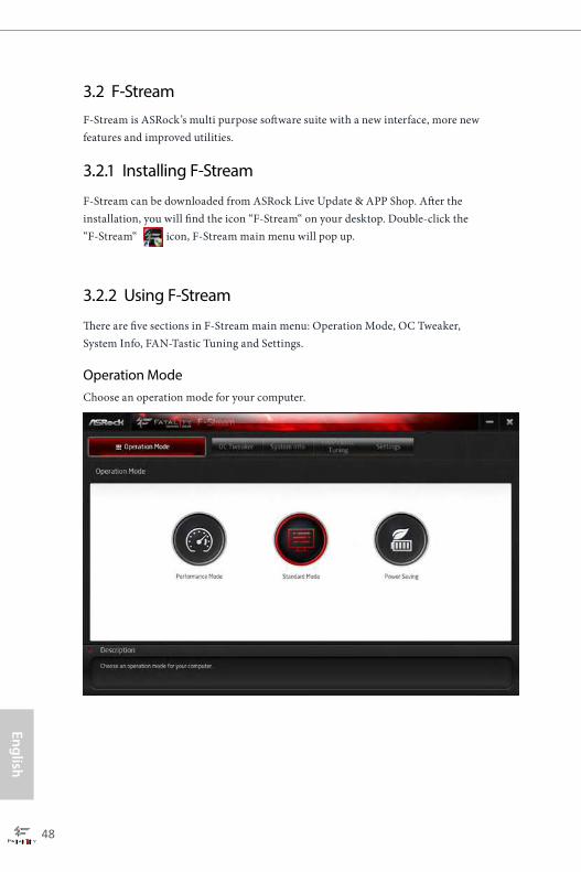
3.2 F-StreamF-Stream is ASRock’s multi purpose software suite with a new interface, more new features and improved utilities.
3.2.1 Installing F-Stream
F-Stream can be downloaded from ASRock Live Update & APP Shop. After the installation, you will find the icon “F-Stream“ on your desktop. Double-click the “F-Stream“ icon, F-Stream main menu will pop up.
3.2.2 Using F-Stream
There are five sections in F-Stream main menu: Operation Mode, OC Tweaker, System Info, FAN-Tastic Tuning and Settings.
Operation ModeChoose an operation mode for your computer.
Engl
ish
Fatal1ty Z370 Professional Gaming i7 Series
49
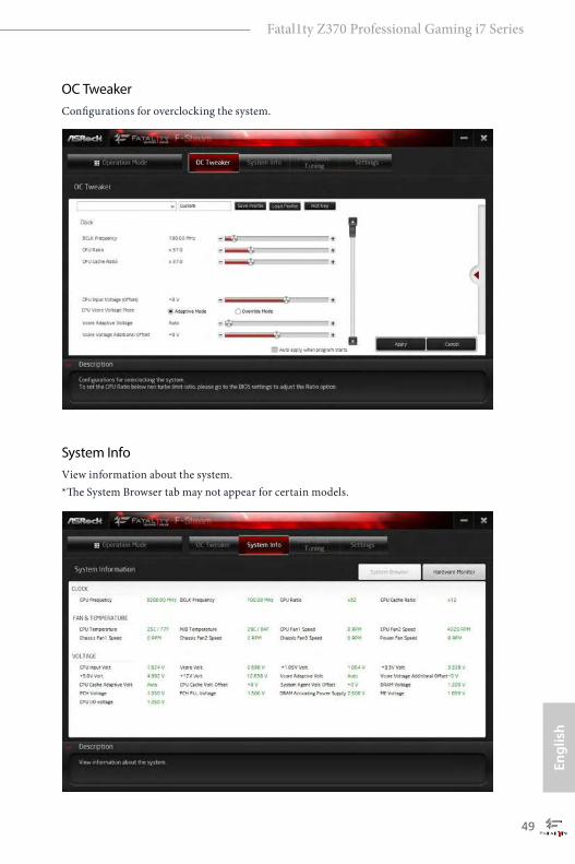
OC TweakerConfigurations for overclocking the system.
System InfoView information about the system. *The System Browser tab may not appear for certain models.
English
50
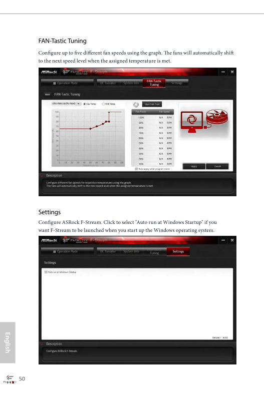
FAN-Tastic Tuning
Configure up to five different fan speeds using the graph. The fans will automatically shift to the next speed level when the assigned temperature is met.
SettingsConfigure ASRock F-Stream. Click to select "Auto run at Windows Startup" if you want F-Stream to be launched when you start up the Windows operating system.
Engl
ish
Fatal1ty Z370 Professional Gaming i7 Series
51
3.3 ASRock Live Update & APP ShopThe ASRock Live Update & APP Shop is an online store for purchasing and downloading software applications for your ASRock computer. You can quickly and easily install various apps and support utilities. With ASRock APP Shop, you can optimize your system and keep your motherboard up to date simply with a few clicks.
Double-click on your desktop to access ASRock Live Update & APP Shop utility.
*You need to be connected to the Internet to download apps from the ASRock Live Update & APP Shop.
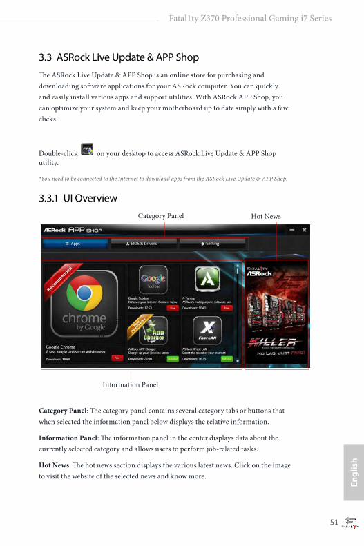
3.3.1 UI Overview
Category Panel: The category panel contains several category tabs or buttons that when selected the information panel below displays the relative information.
Information Panel: The information panel in the center displays data about the currently selected category and allows users to perform job-related tasks.
Hot News: The hot news section displays the various latest news. Click on the image to visit the website of the selected news and know more.
Information Panel
Hot NewsCategory Panel
English
52
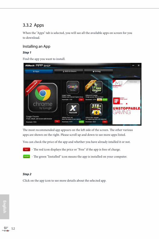
3.3.2 AppsWhen the "Apps" tab is selected, you will see all the available apps on screen for you to download.
Installing an AppStep 1
Find the app you want to install.
The most recommended app appears on the left side of the screen. The other various apps are shown on the right. Please scroll up and down to see more apps listed.
You can check the price of the app and whether you have already intalled it or not.
- The red icon displays the price or "Free" if the app is free of charge.
- The green "Installed" icon means the app is installed on your computer.
Step 2
Click on the app icon to see more details about the selected app.

Engl
ish
Fatal1ty Z370 Professional Gaming i7 Series
53
Step 3
If you want to install the app, click on the red icon to start downloading.
Step 4
When installation completes, you can find the green "Installed" icon appears on the upper right corner.
To uninstall it, simply click on the trash can icon . *The trash icon may not appear for certain apps.
English
54
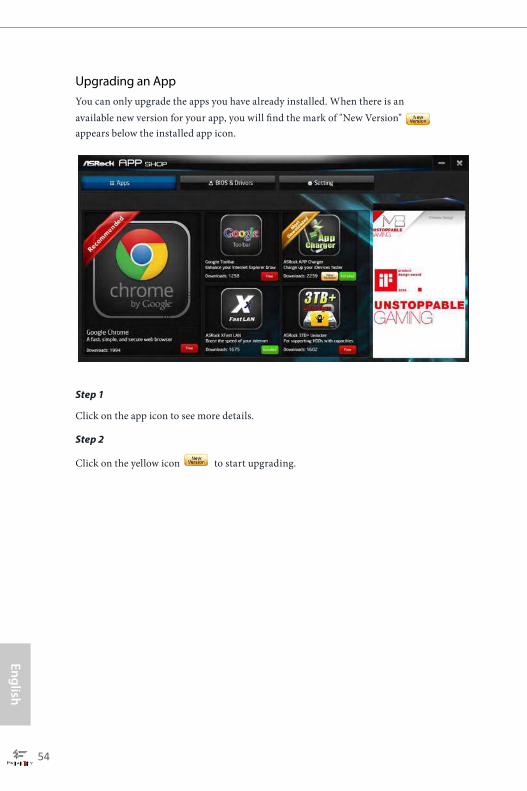
Upgrading an AppYou can only upgrade the apps you have already installed. When there is an available new version for your app, you will find the mark of "New Version" appears below the installed app icon.
Step 1
Click on the app icon to see more details.
Step 2
Click on the yellow icon to start upgrading.
Engl
ish
Fatal1ty Z370 Professional Gaming i7 Series
55
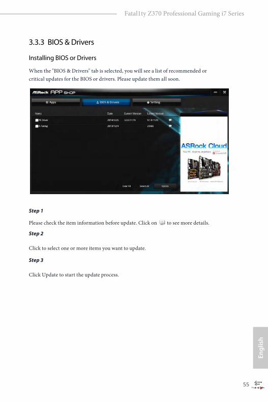
3.3.3 BIOS & Drivers
Installing BIOS or Drivers
When the "BIOS & Drivers" tab is selected, you will see a list of recommended or critical updates for the BIOS or drivers. Please update them all soon.
Step 1
Please check the item information before update. Click on to see more details.
Step 2
Click to select one or more items you want to update.
Step 3
Click Update to start the update process.
English
56
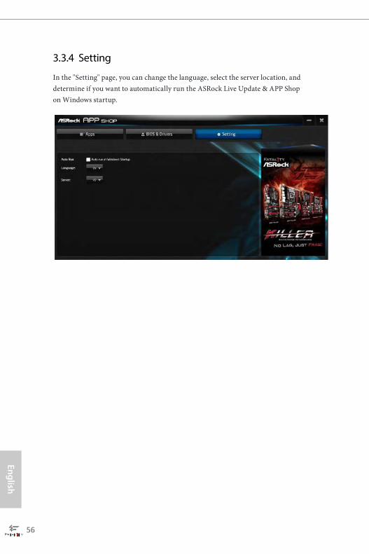
3.3.4 Setting
In the "Setting" page, you can change the language, select the server location, and determine if you want to automatically run the ASRock Live Update & APP Shop on Windows startup.

Engl
ish
Fatal1ty Z370 Professional Gaming i7 Series
57
3.4 Creative SoundBlaster Cinema3The SoundBlasterTM Cinema3, powered by the SBX Pro Studio technologies, is designed to bring the same great audio experience found in live performances, films, and recording studios to the PC. With this utility, you can easily enhance your audio environment in five modes, including Headphones, Speakers, Music, Movie, Game, Voice and Custom.
1 2 3 4 5
There are five functions in SoundBlasterTM Cinema3:
No. Function Description
1 Surround Creating unprecedented levels of audio realism by producing virtual speakers around, above and below you.
2 CrystalizerMaking music sound as good as the artist originally intended by ensuring that every audio detail is heard.
3 BassEnhancing bass sound experience by expanding the low frequency tones.
4 Smart Volume Minimizing abrupt volume changes by automatically adjusting the loudness of your audio playback.
5 Dialog Plus Enhancing voices in music and movies for drastically clearer vocal range.
English
58
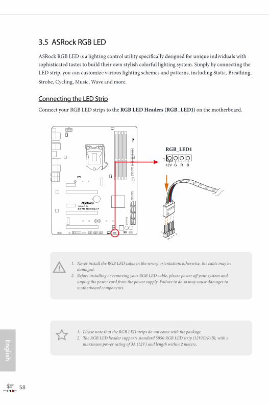
3.5 ASRock RGB LED
ASRock RGB LED is a lighting control utility specifically designed for unique individuals with sophisticated tastes to build their own stylish colorful lighting system. Simply by connecting the LED strip, you can customize various lighting schemes and patterns, including Static, Breathing,
Strobe, Cycling, Music, Wave and more.
Connecting the LED Strip
Connect your RGB LED strips to the RGB LED Headers (RGB_LED1) on the motherboard.
1. Never install the RGB LED cable in the wrong orientation; otherwise, the cable may be damaged.
2. Before installing or removing your RGB LED cable, please power off your system and unplug the power cord from the power supply. Failure to do so may cause damages to motherboard components.
1. Please note that the RGB LED strips do not come with the package.2. The RGB LED header supports standard 5050 RGB LED strip (12V/G/R/B), with a
maximum power rating of 3A (12V) and length within 2 meters.
FATAL TY1
12V G R
B1
12V G R B1
RGB_LED1
Engl
ish
Fatal1ty Z370 Professional Gaming i7 Series
59
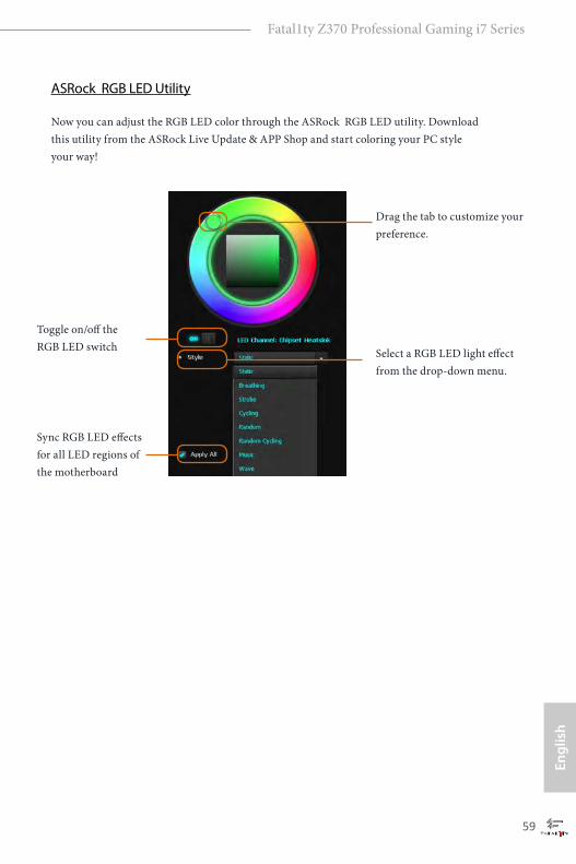
ASRock RGB LED Utility
Now you can adjust the RGB LED color through the ASRock RGB LED utility. Download this utility from the ASRock Live Update & APP Shop and start coloring your PC style your way!
Toggle on/off the RGB LED switch
Sync RGB LED effects for all LED regions of the motherboard
Select a RGB LED light effect from the drop-down menu.
Drag the tab to customize your preference.

English
60
Chapter 4 UEFI SETUP UTILITY
4.1 IntroductionThis section explains how to use the UEFI SETUP UTILITY to configure your system. You may run the UEFI SETUP UTILITY by pressing <F2> or <Del> right after you power on the computer, otherwise, the Power-On-Self-Test (POST) will continue with its test routines. If you wish to enter the UEFI SETUP UTILITY after POST, restart the system by pressing <Ctl> + <Alt> + <Delete>, or by pressing the reset button on the system chassis. You may also restart by turning the system off and then back on.
Because the UEFI software is constantly being updated, the following UEFI setup screens and descriptions are for reference purpose only, and they may not exactly match what you see on your screen.
Engl
ish
Fatal1ty Z370 Professional Gaming i7 Series
61
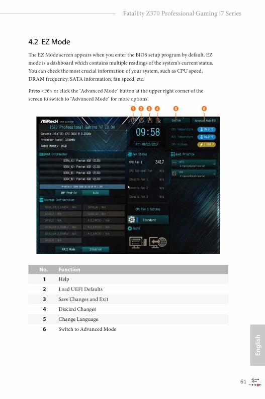
4.2 EZ ModeThe EZ Mode screen appears when you enter the BIOS setup program by default. EZ mode is a dashboard which contains multiple readings of the system’s current status. You can check the most crucial information of your system, such as CPU speed, DRAM frequency, SATA information, fan speed, etc.
Press <F6> or click the "Advanced Mode" button at the upper right corner of the screen to switch to "Advanced Mode" for more options.
No. Function
1 Help
2 Load UEFI Defaults
3 Save Changes and Exit
4 Discard Changes
5 Change Language
6 Switch to Advanced Mode

English
62
4.3 Advanced ModeThe Advanced Mode provides more options to configure the BIOS settings. Refer to the following sections for the detailed configurations.
To access the EZ Mode, press <F6> or click the "EZ Mode" button at the upper right corner of the screen.
4.3.1 UEFI Menu Bar
The top of the screen has a menu bar with the following selections:
Main For setting system time/date information
OC Tweaker For overclocking configurations
Advanced For advanced system configurations
Tool Useful tools
H/W Monitor Displays current hardware status
Security For security settings
Boot For configuring boot settings and boot priority
Exit Exit the current screen or the UEFI Setup Utility

Engl
ish
Fatal1ty Z370 Professional Gaming i7 Series
63
4.3.2 Navigation KeysUse < > key or < > key to choose among the selections on the menu bar, and use < > key or < > key to move the cursor up or down to select items, then press <Enter> to get into the sub screen. You can also use the mouse to click your required item.
Please check the following table for the descriptions of each navigation key.
Navigation Key(s) Description
+ / - To change option for the selected items
<Tab> Switch to next function
<PGUP> Go to the previous page
<PGDN> Go to the next page
<HOME> Go to the top of the screen
<END> Go to the bottom of the screen
<F1> To display the General Help Screen
<F5> Add / Remove Favorite
<F7> Discard changes and exit the SETUP UTILITY
<F9> Load optimal default values for all the settings
<F10> Save changes and exit the SETUP UTILITY
<F12> Print screen
<ESC> Jump to the Exit Screen or exit the current screen

English
64
4.4 Main ScreenWhen you enter the UEFI SETUP UTILITY, the Main screen will appear and display the system overview.
My FavoriteDisplay your collection of BIOS items. Press F5 to add/remove your favorite items.

Engl
ish
Fatal1ty Z370 Professional Gaming i7 Series
65
4.5 OC Tweaker Screen
In the OC Tweaker screen, you can set up overclocking features.
Advanced Turbo
You can use this option to increase your system performance. This option appears only when your CPU supports this function. This option appears only when you adopt K-Series CPU.
Load Optimized CPU OC Setting
You can use this option to load optimized CPU overclocking setting. Please note that overclocking may cause damage to your CPU and motherboard. It should be done at your own risk and expense.
Load Optimized GPU OC Setting
You can use this option to load optimized GPU overclocking setting. Please note that overclocking may cause damage to your GPU and motherboard. It should be done at your own risk and expense. This option appears only when you adopt K-Series CPU.
Because the UEFI software is constantly being updated, the following UEFI setup screens and descriptions are for reference purpose only, and they may not exactly match what you see on your screen.
English
66
CPU Configuration
Multi Core Enhancement Improve the system's performance by forcing the CPU to perform the highest frequency on all CPU cores simultaneously. Disable to reduce power consumption .
CPU RatioThe CPU speed is determined by the CPU Ratio multiplied with the BCLK. Increasing the CPU Ratio will increase the internal CPU clock speed without affecting the clock speed of other components.
CPU Cache RatioThe CPU Internal Bus Speed Ratio. The maximum should be the same as the CPU Ratio.
Minimum CPU Cache Ratio Set the minimum CPU Internal Bus Speed Ratio.
BCLK FrequencyThe CPU speed is determined by the CPU Ratio multiplied with the BCLK. Increasing the BCLK will increase the internal CPU clock speed but also affect the clock speed of other components.
Spread Spectrum
Enable Spread Spectrum to reduce electromagnetic interference for passing EMI tests. Disable to achieve higher clock speeds when overclocking.
CPU BCLK AmplitudeConfigure the CPU BCLK Amplitude.
CPU Slew Rate
Configure the CPU Slew Rate.
CPU PLL ORT
Configure the CPU PLL ORT.
Divider
Configure the BCLK divider.
Boot Performance Mode Default is Max Non-Turbo performance mode. It will keep cpu Flex-ratio till OS

Engl
ish
Fatal1ty Z370 Professional Gaming i7 Series
67
handoff. Max Battery mode will set CPU ratio as x8 till OS handoff. This option is suggested for BCLK overclocking.
Reliability Stress Restrictor
Disable or Enable Reliability Stress Restrictor feature.
FCLK FrequencyConfigure the FCLK Frequency.
AVX Ratio OffsetAVX Ratio Offset specifies a negative offset from the CPU Ratio for AVX workloads. AVX is a more stressful workload that lowers the AVX ratio to ensure maximum possible ratio for SSE workloads.
BCLK Aware Adaptive VoltageBCLK Aware Adaptive Voltage enable/disable. When enabled, pcode will be aware of the BCLK frequency when calculating the CPU V/F curves. This is ideal for BCLK OC to avoid high voltage overrides.
Ring to Core Ratio OffsetDisable Ring to Core Ratio Offset so the ring and core can run at the same frequency.
Intel SpeedStep TechnologyIntel SpeedStep technology allows processors to switch between multiple frequen-cies and voltage points for better power saving and heat dissipation.
Intel Turbo Boost TechnologyIntel Turbo Boost Technology enables the processor to run above its base operating frequency when the operating system requests the highest performance state.
Intel Speed Shift TechnologyEnable/Disable Intel Speed Shift Technology support. Enabling will expose the CPPC v2 interface to allow for hardware controlled P-sates.
Long Duration Power LimitConfigure Package Power Limit 1 in watts. When the limit is exceeded, the CPU ratio will be lowered after a period of time. A lower limit can protect the CPU and save power, while a higher limit may improve performance.
English
68
Long Duration MaintainedConfigure the period of time until the CPU ratio is lowered when the Long Duration Power Limit is exceeded.
Short Duration Power LimitConfigure Package Power Limit 2 in watts. When the limit is exceeded, the CPU ratio will be lowered immediately. A lower limit can protect the CPU and save power, while a higher limit may improve performance.
CPU Core Current LimitConfigure the current limit of the CPU core. A lower limit can protect the CPU and save power, while a higher limit may improve performance.
GT Slice Current LimitConfigure the current limit of the GT slice. A lower limit can protect the CPU and save power, while a higher limit may improve performance.
GT Frequency
Conigure the frequency of the integrated GPU.
DRAM Configuration
DRAM Tweaker
Fine tune the DRAM settings by leaving marks in checkboxes. Click OK to confirm and apply your new settings.
DRAM Timing Configuration
Load XMP SettingLoad XMP settings to overclock the memory and perform beyond standard specifications.
BCLK FrequencyThe CPU speed is determined by the CPU Ratio multiplied with the BCLK. Increasing the BCLK will increase the internal CPU clock speed but also affect the clock speed of other components.
DRAM Frequency Clock
Select Auto for optimized settings.
Engl
ish
Fatal1ty Z370 Professional Gaming i7 Series
69
DRAM FrequencyIf [Auto] is selected, the motherboard will detect the memory module(s) inserted and assign the appropriate frequency automatically.
Primary Timing
CAS# Latency (tCL)
The time between sending a column address to the memory and the beginning of the data in response.
RAS# to CAS# Delay and Row Precharge (tRCDtRP) RAS# to CAS# Delay : The number of clock cycles required between the opening of a row of memory and accessing columns within it. Row Precharge: The number of clock cycles required between the issuing of the precharge command and opening the next row.
RAS# Active Time (tRAS)
The number of clock cycles required between a bank active command and issuing the precharge command.
Command Rate (CR)
The delay between when a memory chip is selected and when the first active command can be issued.
Secondary Timing
Write Recovery Time (tWR)The amount of delay that must elapse after the completion of a valid write operation, before an active bank can be precharged.
Refresh Cycle Time (tRFC)The number of clocks from a Refresh command until the first Activate command to the same rank.
RAS to RAS Delay (tRRD_L) The number of clocks between two rows activated in different banks of the same rank.
RAS to RAS Delay (tRRD_S)
The number of clocks between two rows activated in different banks of the same rank.

English
70
Write to Read Delay (tWTR_L)
The number of clocks between the last valid write operation and the next read command to the same internal bank.
Write to Read Delay (tWTR_S)
The number of clocks between the last valid write operation and the next read command to the same internal bank.
Read to Precharge (tRTP)The number of clocks that are inserted between a read command to a row pre-charge command to the same rank.
Four Activate Window (tFAW)The time window in which four activates are allowed the same rank.
CAS Write Latency (tCWL)Configure CAS Write Latency.
Third Timing
tREFIConfigure refresh cycles at an average periodic interval.
tCKEConfigure the period of time the DDR4 initiates a minimum of one refresh command internally once it enters Self-Refresh mode.
tRDRD_sgConfigure between module read to read delay.
tRDRD_dgConfigure between module read to read delay.
tRDRD_drConfigure between module read to read delay.
tRDRD_ddConfigure between module read to read delay.
tRDWR_sgConfigure between module read to write delay.

Engl
ish
Fatal1ty Z370 Professional Gaming i7 Series
71
tRDWR_dgConfigure between module read to write delay.
tRDWR_drConfigure between module read to write delay.
tRDWR_ddConfigure between module read to write delay.
tWRRD_sgConfigure between module write to read delay.
tWRRD_dgConfigure between module write to read delay.
tWRRD_drConfigure between module write to read delay.
tWRRD_ddConfigure between module write to read delay.
tWRWR_sgConfigure between module write to write delay.
tWRWR_dgConfigure between module write to write delay.
tWRWR_drConfigure between module write to write delay.
tWRWR_ddConfigure between module write to write delay.
Fourth Timing
RTL Init Value Configure round trip latency init value for round trip latency training.
IO-L Init Value Configure IO latency init value for IO latency training.

English
72
RTL (CH A) Configure round trip latency for channel A.
RTL (CH B)
Configure round trip latency for channel B.
IO-L (CH A)
Configure IO latency for channel A.
IO-L (CH B) Configure IO latency for channel B.
IO-L Offset (CH A) Configure IO latency offset for channel A.
IO-L Offset (CH B) Configure IO latency offset for channel B.
RFR Delay (CH A) Configure RFR Delay for Channel A.
RFR Delay (CH B)
Configure RFR Delay for Channel B.
Advanced Setting
ODT WR (CH A)Configure the memory on die termination resistors' WR for channel A.
ODT WR (CH B)Configure the memory on die termination resistors' WR for channel B.
ODT PARK (CH A)Configure the memory on die termination resistors' PARK for channel A.
ODT PARK (CH B)Configure the memory on die termination resistors' PARK for channel B.
ODT NOM (CH A)Use this to change ODT (CH A) Auto/Manual settings. The default is [Auto].

Engl
ish
Fatal1ty Z370 Professional Gaming i7 Series
73
ODT NOM (CH B)
Use this to change ODT (CH B) Auto/Manual settings. The default is [Auto].
Dll Bandwidth 0
Configure the Dll Bandwidth 0.
Dll Bandwidth 1
Configure the Dll Bandwidth 1.
Dll Bandwidth 2
Configure the Dll Bandwidth 2.
Dll Bandwidth 3
Configure the Dll Bandwidth 3.
Command Tristate
Configure the Command Tristate Support.
Realtime Memory Timing
Configure the realtime memory timings.
[Enabled] The system will allow performing realtime memory timing changes after MRC_DONE.
MRC Fast BootEnable Memory Fast Boot to skip DRAM memory training for booting faster.
Voltage Configuration
Voltage Mode[OC] If this option is selected, there is larger range voltage for overclocking.
[Stable] If this option is selected, there is smaller range voltage for stable system.
CPU Core/Cache VoltageConfigure the voltage for the CPU Core/Cache.
CPU Load-Line Calibration
CPU Load-Line Calibration helps prevent CPU voltage droop when the system is under heavy load.

English
74
GT Core/Cache VoltageConfigure the voltage for the CPU Core/Cache.
GT Load-Line Calibration
GPU Load-Line Calibration helps prevent GPU voltage droop when the system is under heavy load.
DRAM VoltageUse this to configure DRAM Voltage. The default value is [Auto].
DRAM Activating Power SupplyConfigure the voltage for the DRAM Activating Power Supply.
VTT DDR Voltage
Configure the VTT DDR Voltage.
PCH +1.0 VoltageConfigure the chipset voltage (1.0V).
PCH PLL VoltageConfigure the PCH PLL voltage.
VCCIO VoltageConfigure the voltage for the VCCIO.
Boot CPU PLL VoltageConfigure the voltage for the Boot CPU PLL.
Eventual CPU PLL VoltageConfigure the voltage for the Eventual CPU PLL.
VCCSA VoltageConfigure the voltage for the VCCSA.
VCC PLL VoltageConfigure the voltage for the VCC PLL.
CPU Cold Bug Killer VoltageCold Bug Killer Voltage. Recommended to set 2.200V~2.400V for Ln2benching. It will solve most of CPU cold bug.

Engl
ish
Fatal1ty Z370 Professional Gaming i7 Series
75
CLK VDD VoltageConfigure the voltage for the CLK VDD.
DMI VoltageConfigure the voltage for the DMI.
CPU Internal PLL VoltageDefault is 0.900V. Each step is 0.015V. Adding 9- 15 steps will helps CPU PLL to lock internal clock during High frequency under Ln2 cooling. For example: 1.020V - 1.125V will be proper value. But the voltage level will be different on each proces-sor. User has to find the best value for your own processor. CPU Vcore Voltage must higher than CPU Internal PLL Voltage, or your processor will hang.
GT PLL VoltageDefault is 0.900V. Each step is 0.015V. Adding 9 -15 steps will help CPU PLL to lock internal clock during High frequency under Ln2 cooling. For example: 1.020V - 1.125V will be proper value. Bu the voltage level will be different on each processor. User has to find the best value for user’s own processor.
Ring PLL VoltageDefault is 0.900V. Each step is 0.015V. Adding 9 -15 steps will help CPU PLL to lock internal clock during High frequency under Ln2 cooling. For example: 1.020V - 1.125V will be proper value. Bu the voltage level will be different on each processor. User has to find the best value for user’s own processor.
System Agent PLL VoltageDefault is 0.900V. Each step is 0.015V. Adding 9 -15 steps will help CPU PLL to lock internal clock during High frequency under Ln2 cooling. For example: 1.020V - 1.125V will be proper value. Bu the voltage level will be different on each processor. User has to find the best value for user’s own processor.
Memory Controller PLL VoltageDefault is 0.900V. Each step is 0.015V. Adding 9 -15 steps will help CPU PLL to lock internal clock during High frequency under Ln2 cooling. For example: 1.020V - 1.125V will be proper value. Bu the voltage level will be different on each processor. User has to find the best value for user’s own processor.
Save User DefaultType a profile name and press enter to save your settings as user default.
English
76
Load User DefaultLoad previously saved user defaults.
Save User UEFI Setup Profile to DiskSave current UEFI settings as an user default profile to disk.
Load User UEFI Setup Profile to DiskLoad previously saved user defaults from the disk.
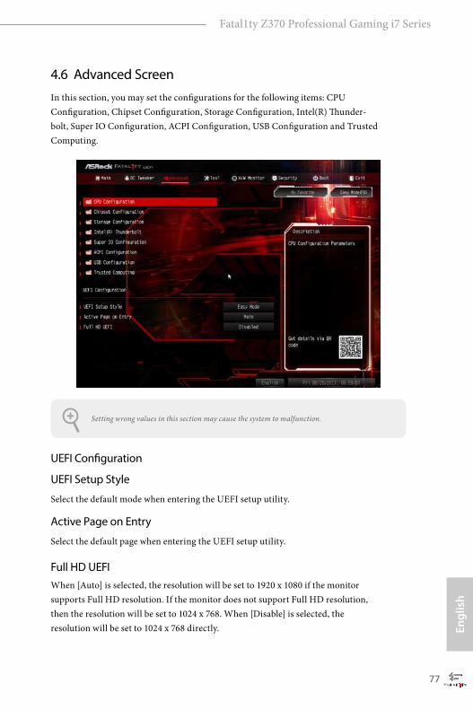
Engl
ish
Fatal1ty Z370 Professional Gaming i7 Series
77
4.6 Advanced ScreenIn this section, you may set the configurations for the following items: CPU Configuration, Chipset Configuration, Storage Configuration, Intel(R) Thunder-bolt, Super IO Configuration, ACPI Configuration, USB Configuration and Trusted Computing.
UEFI Configuration
UEFI Setup Style
Select the default mode when entering the UEFI setup utility.
Active Page on Entry
Select the default page when entering the UEFI setup utility.
Full HD UEFIWhen [Auto] is selected, the resolution will be set to 1920 x 1080 if the monitor supports Full HD resolution. If the monitor does not support Full HD resolution, then the resolution will be set to 1024 x 768. When [Disable] is selected, the resolution will be set to 1024 x 768 directly.
Setting wrong values in this section may cause the system to malfunction.
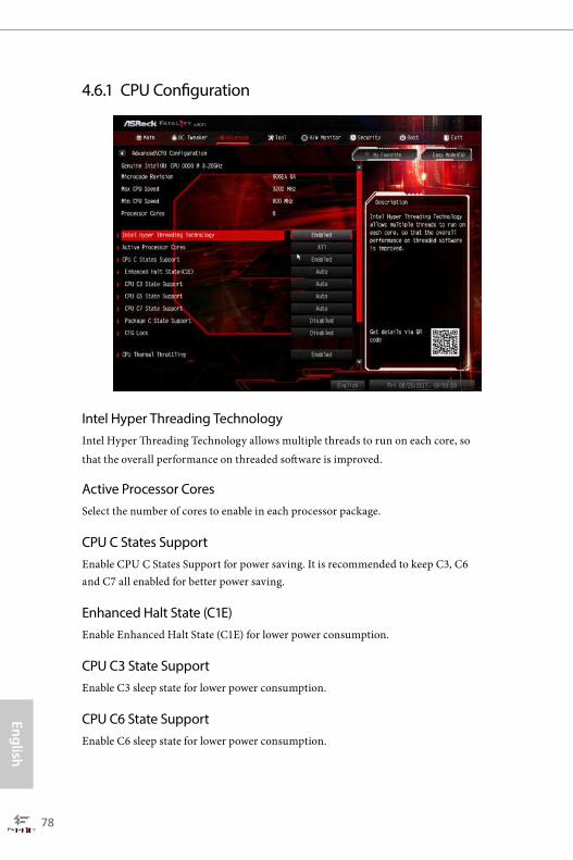
English
78
4.6.1 CPU Configuration
Intel Hyper Threading TechnologyIntel Hyper Threading Technology allows multiple threads to run on each core, so that the overall performance on threaded software is improved.
Active Processor CoresSelect the number of cores to enable in each processor package.
CPU C States SupportEnable CPU C States Support for power saving. It is recommended to keep C3, C6 and C7 all enabled for better power saving.
Enhanced Halt State (C1E)Enable Enhanced Halt State (C1E) for lower power consumption.
CPU C3 State SupportEnable C3 sleep state for lower power consumption.
CPU C6 State SupportEnable C6 sleep state for lower power consumption.

Engl
ish
Fatal1ty Z370 Professional Gaming i7 Series
79
CPU C7 State SupportEnable C7 sleep state for lower power consumption.
Package C State Support
Enable CPU, PCIe, Memory, Graphics C State Support for power saving.
CFG Lock
This item allows you to disable or enable the CFG Lock.
CPU Thermal ThrottlingEnable CPU internal thermal control mechanisms to keep the CPU from overheat-ing.
Intel Virtualization TechnologyIntel Virtualization Technology allows a platform to run multiple operating systems and applications in independent partitions, so that one computer system can function as multiple virtual systems.
Hardware PrefetcherAutomatically prefetch data and code for the processor. Enable for better performance.
Adjacent Cache Line PrefetchAutomatically prefetch the subsequent cache line while retrieving the currently requested cache line. Enable for better performance.
Software Guard Extensions (SGX)Use this item to enable or disable Software Controlled Software Guard Extensions (SGX).
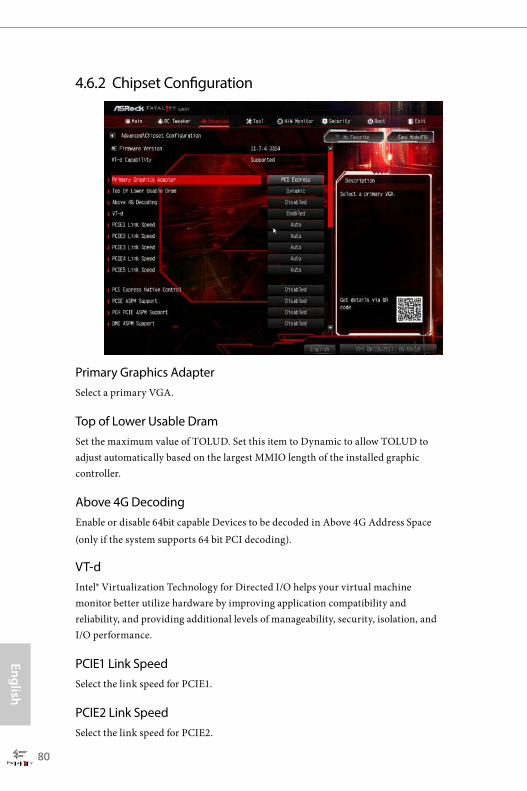
English
80
4.6.2 Chipset Configuration
Primary Graphics Adapter Select a primary VGA.
Top of Lower Usable Dram Set the maximum value of TOLUD. Set this item to Dynamic to allow TOLUD to adjust automatically based on the largest MMIO length of the installed graphic controller.
Above 4G DecodingEnable or disable 64bit capable Devices to be decoded in Above 4G Address Space (only if the system supports 64 bit PCI decoding).
VT-dIntel® Virtualization Technology for Directed I/O helps your virtual machine monitor better utilize hardware by improving application compatibility and reliability, and providing additional levels of manageability, security, isolation, and I/O performance.
PCIE1 Link SpeedSelect the link speed for PCIE1.
PCIE2 Link SpeedSelect the link speed for PCIE2.
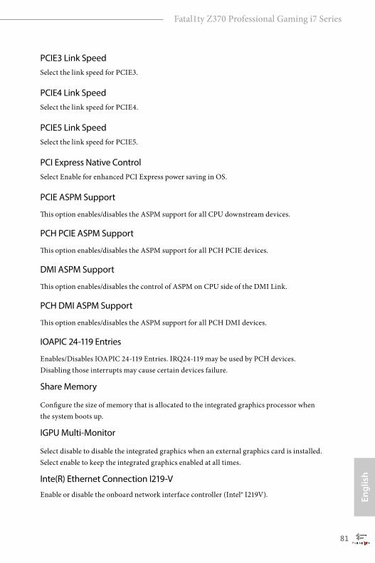
Engl
ish
Fatal1ty Z370 Professional Gaming i7 Series
81
PCIE3 Link SpeedSelect the link speed for PCIE3.
PCIE4 Link SpeedSelect the link speed for PCIE4.
PCIE5 Link SpeedSelect the link speed for PCIE5.
PCI Express Native ControlSelect Enable for enhanced PCI Express power saving in OS.
PCIE ASPM Support
This option enables/disables the ASPM support for all CPU downstream devices.
PCH PCIE ASPM Support
This option enables/disables the ASPM support for all PCH PCIE devices.
DMI ASPM Support
This option enables/disables the control of ASPM on CPU side of the DMI Link.
PCH DMI ASPM Support
This option enables/disables the ASPM support for all PCH DMI devices.
IOAPIC 24-119 Entries
Enables/Disables IOAPIC 24-119 Entries. IRQ24-119 may be used by PCH devices. Disabling those interrupts may cause certain devices failure.
Share Memory
Configure the size of memory that is allocated to the integrated graphics processor when the system boots up.
IGPU Multi-Monitor
Select disable to disable the integrated graphics when an external graphics card is installed. Select enable to keep the integrated graphics enabled at all times.
Inte(R) Ethernet Connection I219-V
Enable or disable the onboard network interface controller (Intel® I219V).

English
82
Inte(R) Ethernet Controller I211
Enable or disable the onboard network interface controller (Intel® I211AT).
Aquantia 10G LAN
Enable or disable the Aquantia 10G LAN.
Onboard HD AudioEnable/disable onboard HD audio. Set to Auto to enable onboard HD audio and automatically disable it when a sound card is installed.
Front PanelEnable/disable front panel HD audio.
Onboard HDMI HD AudioEnable audio for the onboard digital outputs.
WAN RadioEnable/disable the WiFi module's connectivity.
Deep SleepConfigure deep sleep mode for power saving when the computer is shut down.
Restore on AC/Power LossSelect the power state after a power failure. If [Power Off] is selected, the power will remain off when the power recovers. If [Power On] is selected, the system will start to boot up when the power recovers.
Turn On LED in S5Turn on/off the LED in the ACPI S5 state.
BIOS Backup SwitchConfigure BIOS Backup Switch function.
Onboard Debug Port LEDEnable/disable the onboard Dr. Debug LED.
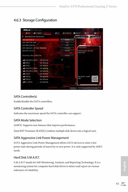
Engl
ish
Fatal1ty Z370 Professional Gaming i7 Series
83
4.6.3 Storage Configuration
SATA Controller(s)Enable/disable the SATA controllers.
SATA Controller SpeedIndicates the maximum speed the SATA controller can support.
SATA Mode Selection[AHCI] Supports new features that improve performance.
[Intel RST Premium (RAID)] Combine multiple disk drives into a logical unit.
SATA Aggressive Link Power ManagementSATA Aggressive Link Power Management allows SATA devices to enter a low power state during periods of inactivity to save power. It is only supported by AHCI mode.
Hard Disk S.M.A.R.T. S.M.A.R.T stands for Self-Monitoring, Analysis, and Reporting Technology. It is a monitoring system for computer hard disk drives to detect and report on various indicators of reliability.

English
84
Third Party SATA 3 ControllerEnable or disable the third party SATA3 controller.
Engl
ish
Fatal1ty Z370 Professional Gaming i7 Series
85
4.6.4 Intel® Thunderbolt
Intel® Thunderbolt TechnologyEnable or disable the Intel® Thunderbolt™ function.
Security LevelAllows you to choose a security level for the Thunderbolt ports.
AR AIC SupportEnable or disable to support AR AIC card.
TBT Host RouterEnable the host router based on ports available.

English
86
4.6.5 Super IO Configuration
PS2 Y-CableEnable the PS2 Y-Cable or set this option to Auto.
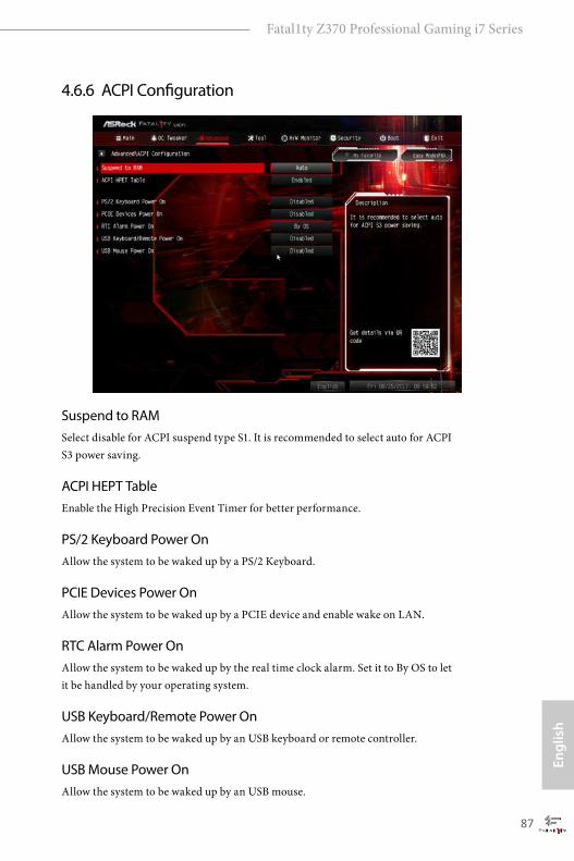
Engl
ish
Fatal1ty Z370 Professional Gaming i7 Series
87
4.6.6 ACPI Configuration
Suspend to RAMSelect disable for ACPI suspend type S1. It is recommended to select auto for ACPI S3 power saving.
ACPI HEPT TableEnable the High Precision Event Timer for better performance.
PS/2 Keyboard Power OnAllow the system to be waked up by a PS/2 Keyboard.
PCIE Devices Power OnAllow the system to be waked up by a PCIE device and enable wake on LAN.
RTC Alarm Power OnAllow the system to be waked up by the real time clock alarm. Set it to By OS to let it be handled by your operating system.
USB Keyboard/Remote Power OnAllow the system to be waked up by an USB keyboard or remote controller.
USB Mouse Power OnAllow the system to be waked up by an USB mouse.
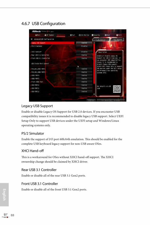
English
88
4.6.7 USB Configuration
Legacy USB SupportEnable or disable Legacy OS Support for USB 2.0 devices. If you encounter USB compatibility issues it is recommended to disable legacy USB support. Select UEFI Setup Only to support USB devices under the UEFI setup and Windows/Linux operating systems only.
PS/2 Simulator Enable the support of I/O port 60h/64h emulation. This should be enabled for the complete USB keyboard legacy support for non-USB aware OSes.
XHCI Hand-off
This is a workaround for OSes without XHCI hand-off support. The XHCI ownership change should be claimed by XHCI driver.
Rear USB 3.1 ControllerEnable or disable all of the rear USB 3.1 Gen2 ports.
Front USB 3.1 ControllerEnable or disable all of the front USB 3.1 Gen2 ports.
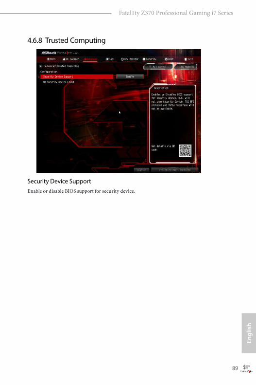
Engl
ish
Fatal1ty Z370 Professional Gaming i7 Series
89
4.6.8 Trusted Computing
Security Device SupportEnable or disable BIOS support for security device.

English
90
4.7 Tools
RGB LED RGB LED and header allows users to connect LED strip and create their unique PC style easily.
UEFI Tech ServiceContact ASRock Tech Service if you are having trouble with your PC. Please setup network configuration before using UEFI Tech Service.
Easy RAID InstallerEasy RAID Installer helps you to copy the RAID driver from the support CD to your USB storage device. After copying the drivers please change the SATA mode to RAID, then you can start installing the operating system in RAID mode.
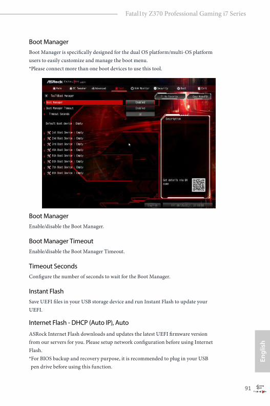
Engl
ish
Fatal1ty Z370 Professional Gaming i7 Series
91
Boot ManagerBoot Manager is specifically designed for the dual OS platform/multi-OS platform users to easily customize and manage the boot menu. *Please connect more than one boot devices to use this tool.
Boot ManagerEnable/disable the Boot Manager.
Boot Manager TimeoutEnable/disable the Boot Manager Timeout.
Timeout SecondsConfigure the number of seconds to wait for the Boot Manager.
Instant FlashSave UEFI files in your USB storage device and run Instant Flash to update your UEFI.
Internet Flash - DHCP (Auto IP), Auto
ASRock Internet Flash downloads and updates the latest UEFI firmware version from our servers for you. Please setup network configuration before using Internet Flash. *For BIOS backup and recovery purpose, it is recommended to plug in your USB pen drive before using this function.
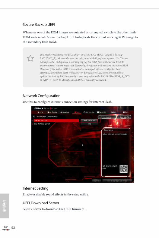
English
92
Secure Backup UEFI
Whenever one of the ROM images are outdated or corrupted, switch to the other flash ROM and execute Secure Backup UEFI to duplicate the current working ROM image to the secondary flash ROM.
Network ConfigurationUse this to configure internet connection settings for Internet Flash.
Internet SettingEnable or disable sound effects in the setup utility.
UEFI Download ServerSelect a server to download the UEFI firmware.
This motherboard has two BIOS chips, an active BIOS (BIOS_A) and a backup BIOS (BIOS_B), which enhances the safety and stability of your system. Use “Secure Backup UEFI” to duplicate a working copy of the BIOS files to the active BIOS to ensure normal system operation. Normally, the system will work on the active BIOS. However if the active BIOS is corrupted or damaged, after several failed boot attempts, the backup BIOS will take over. For safety issues, users are not able to update the backup BIOS manually. Users may refer to the BIOS LEDs (BIOS_A_LED or BIOS_B_LED) to identify which BIOS is currently activated.

Engl
ish
Fatal1ty Z370 Professional Gaming i7 Series
93
4.8 Hardware Health Event Monitoring ScreenThis section allows you to monitor the status of the hardware on your system, including the parameters of the CPU temperature, motherboard temperature, fan speed and voltage.
Fan Tuning
Measure Fan Min Duty Cycle.
Fan-Tastic TuningSelect a fan mode for CPU Fans 1&2, or choose Customize to set 5 CPU temperatures and assign a respective fan speed for each temperature.
CPU Fan 1 Setting
Select a fan mode for CPU Fans 1, or choose Customize to set 5 CPU temperatures and assign a respective fan speed for each temperature.
CPU Fan Step Up
Set the value of CPU Fan Step Up.
CPU Fan Step Down
Set the value of CPU Fan Step Down.
English
94
CPU_OPT / W_Pump SwitchSelect CPU Optional or Water Pump mode.
CPU Optional Fan Control Mode
Select PWM mode or DC mode for CPU Optional fan.
CPU Optional Fan SettingSelect a fan mode for CPU Optional fan, or choose Customize to set 5 CPU temperatures and assign a respective fan speed for each temperature.
CPU Optional Fan Temp Source
Select a fan temperature source for CPU Optional fan.
CPU Optional Fan Step Up
Set the value of CPU Optional fan Step Up.
CPU Optional Fan Step Down
Set the value of CPU Optional fan Step Down.
Chassis Fan 1 SettingSelect a fan mode for Chassis Fan 1, or choose Customize to set 5 CPU temperatures and assign a respective fan speed for each temperature.
Chassis Fan 1 Temp Source
Select a fan temperature source for Chassis Fan 1.
Chassis Fan 1 Step Up
Set the value of Chassis Fan 1 Step Up.
Chassis Fan 1 Step Down
Set the value of Chassis Fan 1 Step Down.
Chassis Fan 2 SettingSelect a fan mode for Chassis Fan 2, or choose Customize to set 5 CPU temperatures and assign a respective fan speed for each temperature.
Chassis Fan 2 Temp Source
Select a fan temperature source for Chassis Fan 2.

Engl
ish
Fatal1ty Z370 Professional Gaming i7 Series
95
Chassis Fan 2 Step Up
Set the value of Chassis Fan 2 Step Up.
Chassis Fan 2 Step Down
Set the value of Chassis Fan 2 Step Down.
CHA_FAN3 / W_Pump SwitchSelect CHA_FAN3/CPU Optional or Water Pump mode.
Chassis Fan 3 Control Mode
Select PWM mode or DC mode for Chassis Fan 3.
Chassis Fan 3 SettingSelect a fan mode for Chassis Fan 3, or choose Customize to set 5 CPU temperatures and assign a respective fan speed for each temperature.
Chassis Fan 3 Temp Source
Select a fan temperature source for Chassis Fan 3.
Chassis Fan 3 Step Up
Set the value of Chassis Fan 3 Step Up.
Chassis Fan 3 Step Down
Set the value of Chassis Fan 3 Step Down.
Over Temperature ProtectionWhen Over Temperature Protection is enabled, the system automatically shuts down when the motherboard is overheated.

English
96
4.9 Security ScreenIn this section you may set or change the supervisor/user password for the system. You may also clear the user password.
Supervisor PasswordSet or change the password for the administrator account. Only the administrator has authority to change the settings in the UEFI Setup Utility. Leave it blank and press enter to remove the password.
User PasswordSet or change the password for the user account. Users are unable to change the settings in the UEFI Setup Utility. Leave it blank and press enter to remove the password.
Secure BootUse this item to enable or disable support for Secure Boot.
Intel(R) Platform Trust TechnologyEnable/disable Intel PTT in ME. Disable this option to use discrete TPM Module.

Engl
ish
Fatal1ty Z370 Professional Gaming i7 Series
97
4.10 Boot ScreenThis section displays the available devices on your system for you to configure the boot settings and the boot priority.
Fast Boot Fast Boot minimizes your computer's boot time. In fast mode you may not boot from an USB storage device. The VBIOS must support UEFI GOP if you are using an external graphics card. Please notice that Ultra Fast mode will boot so fast that the only way to enter this UEFI Setup Utility is to Clear CMOS or run the Restart to UEFI utility in Windows.
Boot From Onboard LANAllow the system to be waked up by the onboard LAN.
Setup Prompt Timeout
Configure the number of seconds to wait for the setup hot key.
Bootup Num-LockSelect whether Num Lock should be turned on or off when the system boots up.
Boot Beep
Select whether the Boot Beep should be turned on or off when the system boots up. Please note that a buzzer is needed.

English
98
Full Screen LogoEnable to display the boot logo or disable to show normal POST messages.
AddOn ROM DisplayEnable AddOn ROM Display to see the AddOn ROM messages or configure the AddOn ROM if you've enabled Full Screen Logo. Disable for faster boot speed.
Boot Failure Guard MessageIf the computer fails to boot for a number of times the system automatically restores the default settings.
CSM (Compatibility Support Module)
CSM Enable to launch the Compatibility Support Module. Please do not disable unless you’re running a WHCK test.
Launch PXE OpROM Policy
Select UEFI only to run those that support UEFI option ROM only. Select Legacy only to run those that support legacy option ROM only. Select Do not launch to not execute both legacy and UEFI option ROM.

Engl
ish
Fatal1ty Z370 Professional Gaming i7 Series
99
Launch Storage OpROM PolicySelect UEFI only to run those that support UEFI option ROM only. Select Legacy only to run those that support legacy option ROM only. Select Do not launch to not execute both legacy and UEFI option ROM.
Launch Video OpROM Policy Select UEFI only to run those that support UEFI option ROM only. Select Legacy only to run those that support legacy option ROM only. Select Do not launch to not execute both legacy and UEFI option ROM.
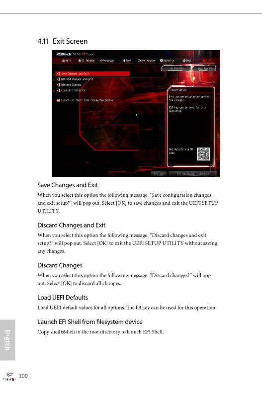
English
100
4.11 Exit Screen
Save Changes and ExitWhen you select this option the following message, “Save configuration changes and exit setup?” will pop out. Select [OK] to save changes and exit the UEFI SETUP UTILITY.
Discard Changes and ExitWhen you select this option the following message, “Discard changes and exit setup?” will pop out. Select [OK] to exit the UEFI SETUP UTILITY without saving any changes.
Discard ChangesWhen you select this option the following message, “Discard changes?” will pop out. Select [OK] to discard all changes.
Load UEFI DefaultsLoad UEFI default values for all options. The F9 key can be used for this operation.
Launch EFI Shell from filesystem deviceCopy shellx64.efi to the root directory to launch EFI Shell.

Contact Information
If you need to contact ASRock or want to know more about ASRock, you’re welcome to visit ASRock’s website at http://www.asrock.com; or you may contact your dealer for further information. For technical questions, please submit a support request form at https://event.asrock.com/tsd.asp
ASRock Incorporation2F., No.37, Sec. 2, Jhongyang S. Rd., Beitou District,
Taipei City 112, Taiwan (R.O.C.)
ASRock EUROPE B.V.Bijsterhuizen 11-11
6546 AR Nijmegen
The Netherlands
Phone: +31-24-345-44-33
Fax: +31-24-345-44-38
ASRock America, Inc.13848 Magnolia Ave, Chino, CA91710
U.S.A.
Phone: +1-909-590-8308
Fax: +1-909-590-1026

DECLARATION OF CONFORMITY
Per FCC Part 2 Section 2.1077(a)
Responsible Party Name: ASRock Incorporation
Address: 13848 Magnolia Ave, Chino, CA91710
+1-909-590-8308/+1-909-590-1026
Phone/Fax No:
hereby declares that the product
Product Name : Motherboard
Model Number :
Conforms to the following speci�cations:
FCC Part 15, Subpart B, Unintentional Radiators
Supplementary Information:
�is device complies with part 15 of the FCC Rules. Operation is subject to the following two conditions: (1) �is device may not cause harmful interference, and (2) this device must accept any interference received, including interference that may cause undesired operation. Representative Person’s Name: James
Signature :
Date : May 12, 2017
Fatal1ty Z370 Professional Gaming i7 Series

EU Declaration of Conformity For the following equipment:
Motherboard(Product Name)
Fatal1ty Z370 Professional Gaming i7 Series / ASRock(Model Designation / Trade Name)
ASRock Incorporation(Manufacturer Name)
2F., No.37, Sec. 2, Jhongyang S. Rd., Beitou District, Taipei City 112, Taiwan (R.O.C.)(Manufacturer Address)
ASRock EUROPE B.V.(Company Name)
Bijsterhuizen 1111 6546 AR Nijmegen The Netherlands(Company Address)
Person responsible for making this declaration:
(Name, Surname)A.V.P(Position / Title)September 27, 2017(Date)
P/N: 15G062051010AK V1.0
EMC —Directive 2014/30/EU (from April 20th, 2016) ☐ EN 55022:2010/AC:2011 Class B EN 55024:2010/A1:2015
EN 55032:2012+AC:2013 Class B EN 61000-3-3:2013 EN 61000-3-2:2014
RED—Directive 2014/53/EU EN 300 328 V2.1.1 EN 301 489-17 V3.1.1
☐☐
☐☐
EN 301 893 V2.1.1 ☐ EN 301 489-3 V2.1.1 ☐ EN 300 220 V3.1.1
LVD —Directive 2014/35/EU (from April 20th, 2016) EN 60950-1 : 2011+ A2: 2013 ☐ EN 60950-1 : 2006/A12: 2011
RoHS — Directive 2011/65/EU CE marking
(EU conformity marking)