vehicle air conditioning compact …...air conditioning system operation places additional load onto...
TRANSCRIPT

VEHICLE AIR CONDITIONING
COMPACT KNOWLEDGE FOR THE GARAGE

Thermal management means optimum engine temperature in all operating states and heating and cooling of the vehicle interior. A modern thermal management system therefore consists of engine cooling and air conditioning components.
Components of these two sub-assemblies which interact with each other often form a unit. In this booklet we describe modern air conditioning systems and their technical background. In this context, we also discuss their function, causes of failure, special features and diagnostic methods.
What is thermal management?

Page
AIR CONDITIONING BASICS
Air conditioning check and air conditioning service 04Air conditioning and cooling unit 05Air conditioning circuit 06Components of the air conditioning system 07Repair and service 14Removal and installation instructions 15Fault diagnostics 18
COMPRESSOR
Removal/installation and troubleshooting of air conditioning compressors 20Repair and replacement of air conditioning compressors 22Compressor damage 26Development of noise 28Kompressoren ohne Magnetkupplung 30
MAINTENANCE AND REPAIRS
Flushing the air conditioning system 35Leak detection technologies 40Repair of pipes and tubes 42
TECHNOLOGY TIPS
Refrigerant R12, R134a, R1234yf 43Interior temperature sensors 44Sealants 45
INNOVATIVE AIR CONDITIONING MANAGEMENT
Innovative air conditioning and interior comfort management 46Thermal Management in hybrid vehicles 50
COMPRESSOR OILS
PAG, PAO and POE air conditioning compressor oils 58Comparison of compressor oils 63Product overview 64
CONTENTS

AIR CONDITIONING BASICS
AIR CONDITIONING CHECK AND
AIR CONDITIONING SERVICE
Alternating air conditioning check and air conditioning service
Air conditioning check and air conditioning service can be compared to small and large inspection:
Info box
Behr Hella Service recommends: Perform the air conditioning check every 12 months and the air conditioning service every 2 years.
What should be done when?
What? Air conditioning check
When? Every 12 months
Why? The interior filter filters dust, pollen and dirt particles out of the air before it flows clean and cooled into the interior. Like with any other filter, the absorption capacity of this filter is limited. There is an evaporator in every air conditioning system. Condensation forms in its fins. With time, bacteria, fungi and micro-organisms settle here. For this reason, the evaporator must be disinfected regularly.
What does it involve? � Visual inspection of all components � Function and performance test
� Replacement of the interior filter � If needed, disinfection of evaporator
What should be done when?
What? Air conditioning service
When? Every 2 years
Why? Up to 10 % of the refrigerant escapes per year, even from a new air conditioning system. A normal process which does, however, reduce cooling capacity and threaten compressor damage. The refrigerant is freed from humidity and contaminants by the filter dryer.
What does it involve? � Visual inspection of all components � Function and performance test � Filter dryer replacement � If needed, disinfection of evaporator
� Refrigerant replacement � Leak test � Replacement of the interior filter

| 54
AIR CONDITIONING AND COOLING UNIT
Consider air conditioning and cooling as unit
Although the air conditioning system and the engine cooling system are two separate systems, they influence one another. Air conditioning system operation places additional load onto the engine cooling system and the coolant temperature rises.
The additives contained in the coolant do not only protect against frost, but also against engine overheating. The proper coolant composition increases the boiling point of the medium to above 120 °C. An enormous performance reserve. This is particularly important in the summer, when air conditioning system and cooling system are heavily burdened by ambient temperatures and long trips. The best approach is to check the coolant during air conditioning service as well.

AIR CONDITIONING BASICS
AIR CONDITIONING CIRCUIT
Refrigerant circuit with expansion valve
How the air conditioning system with expansion valve works
For controlling the climate in the vehicle interior,refrigerant circuit as well as coolant circuit are required. Amixture of cold and warm air allows the generation of thedesired climate conditions - completely independently fromouter conditions. As a result, the air conditioning systembecomes an important factor for safety and driving comfort. The individual components of the refrigerant circuit are connected by tubes and/or aluminium pipes and thus form a closed system. Refrigerant and refrigerant oil circulate in the system, driven by the compressor. The circuit has two sides:
� The section between the compressor and the expansion valve is the high pressure side (yellow/red).
� The section between the expansion valve and the compressor is the low pressure side (blue).
The gaseous refrigerant is compressed by the compressor (thereby significantly increasing its temperature) and pressed under high pressure through the condenser. This removes heat from refrigerant - it condensates and changes its state from gas to liquid.
The filter dryer, the next unit, removes contaminants and air from the liquid refrigerant as well as humidity. This ensures system effectiveness and protects the components from damage caused by contaminants.
Condenser fan
Compressor
Filter dryer
Evaporator
Expansion valve
Interior fanCondenser
| 76
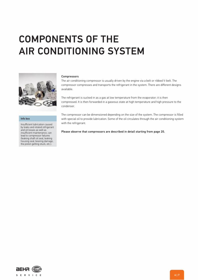
Compressors
The air conditioning compressor is usually driven by the engine via a belt or ribbed V-belt. Thecompressor compresses and transports the refrigerant in the system. There are different designsavailable.
The refrigerant is sucked in as a gas at low temperature from the evaporator; it is then compressed. It is then forwarded in a gaseous state at high temperature and high pressure to the condenser.
The compressor can be dimensioned depending on the size of the system. The compressor is filled with special oil to provide lubrication. Some of the oil circulates through the air conditioning system with the refrigerant.
Please observe that compressors are described in detail starting from page 20.
COMPONENTS OF THE
AIR CONDITIONING SYSTEM
Info box
Insufficient lubrication caused by leaks and related refrigerant and oil losses as well as insufficient maintenance, can lead to compressor failures (leaking shaft oil seal, leaking housing seal, bearing damage, the piston getting stuck, etc.).

AIR CONDITIONING BASICS
Condensers
The capacitor is needed in order to cool the refrigerant that is heated up by the compression in the compressor. The hot refrigerant gas flows into the condenser and transfers heat to the surroundings via the pipe and fins. As it cools down, the state of the refrigerant changes again from gaseous to liquid.
How they work
The hot refrigerant gas flows on top into the condenser and transfers heat to the surroundings viathe pipe and fins. Due to cooling down the refrigerant exists the condenser at the lower connectionin liquid state.
Effects of failure
A defective condenser may exhibit the following symptoms: � Poor cooling performance � Failure of the air conditioning system � Continuously running condenser fan
Causes for occurring faults can be: � Leaks at the connections or caused by damage � Insufficient heat exchange due to contamination
Troubleshooting
Test steps for fault elimination: � Check condenser for contamination � Check for leaks � Pressure test on the high and low pressure sides
Info box
Due to the special installation location, failures of environ-mental nature can occur caused by contamination or stone chipping. Defects caused by front-impact accidents occur particularly often.
| 98
Info box
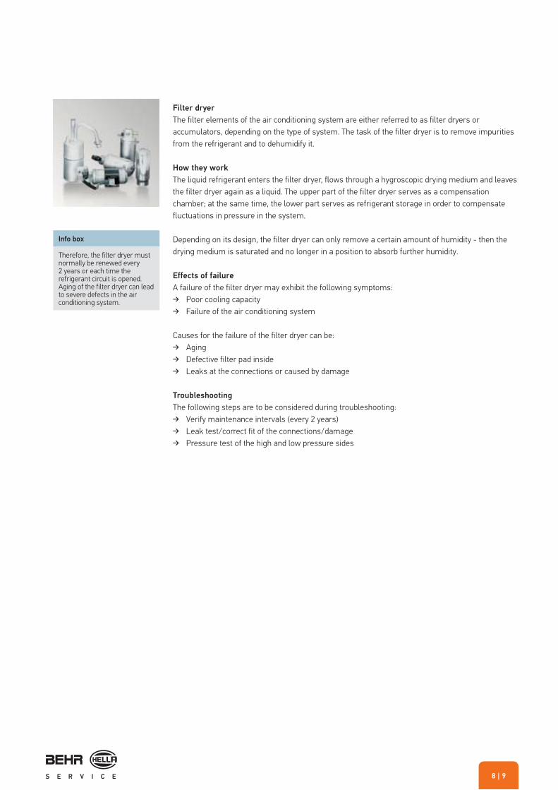
Therefore, the filter dryer must normally be renewed every 2 years or each time the refrigerant circuit is opened. Aging of the filter dryer can lead to severe defects in the air conditioning system.
Filter dryer
The filter elements of the air conditioning system are either referred to as filter dryers or accumulators, depending on the type of system. The task of the filter dryer is to remove impurities from the refrigerant and to dehumidify it.
How they work
The liquid refrigerant enters the filter dryer, flows through a hygroscopic drying medium and leaves the filter dryer again as a liquid. The upper part of the filter dryer serves as a compensation chamber; at the same time, the lower part serves as refrigerant storage in order to compensate fluctuations in pressure in the system.
Depending on its design, the filter dryer can only remove a certain amount of humidity - then the drying medium is saturated and no longer in a position to absorb further humidity.
Effects of failure A failure of the filter dryer may exhibit the following symptoms:
� Poor cooling capacity � Failure of the air conditioning system
Causes for the failure of the filter dryer can be: � Aging � Defective filter pad inside � Leaks at the connections or caused by damage
Troubleshooting
The following steps are to be considered during troubleshooting: � Verify maintenance intervals (every 2 years) � Leak test/correct fit of the connections/damage � Pressure test of the high and low pressure sides
AIR CONDITIONING BASICS
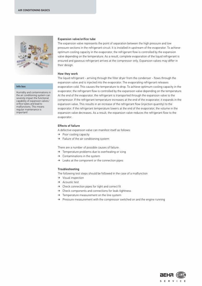
Expansion valve/orifice tube
The expansion valve represents the point of separation between the high pressure and low pressure sections in the refrigerant circuit. It is installed in upstream of the evaporator. To achieve optimum cooling capacity in the evaporator, the refrigerant flow is controlled by the expansion valve depending on the temperature. As a result, complete evaporation of the liquid refrigerant is ensured and gaseous refrigerant arrives at the compressor only. Expansion valves may differ in their design.
How they work
The liquid refrigerant - arriving through the filter dryer from the condenser - flows through the expansion valve and is injected into the evaporator. The evaporating refrigerant releases evaporation cold. This causes the temperature to drop. To achieve optimum cooling capacity in the evaporator, the refrigerant flow is controlled by the expansion valve depending on the temperature. At the end of the evaporator, the refrigerant is transported through the expansion valve to the compressor. If the refrigerant temperature increases at the end of the evaporator, it expands in the expansion valve. This results in an increase of the refrigerant flow (injection quantity) to the evaporator. If the refrigerant temperature lowers at the end of the evaporator, the volume in the expansion valve decreases. As a result, the expansion valve reduces the refrigerant flow to the evaporator.
Effects of failure
A defective expansion valve can manifest itself as follows: � Poor cooling capacity � Failure of the air conditioning system
There are a number of possible causes of failure: � Temperature problems due to overheating or icing � Contaminations in the system � Leaks at the component or the connection pipes
Troubleshooting
The following test steps should be followed in the case of a malfunction � Visual inspection � Acoustic test � Check connection pipes for tight and correct fit � Check components and connections for leak-tightness � Temperature measurement on the line system � Pressure measurement with the compressor switched on and the engine running
Info box
Humidity and contaminations in the air conditioning system can severely impact the functional capability of expansion valves/orifice tubes and lead to malfunctions. This means regular maintenance is important!
| 1110
Info box
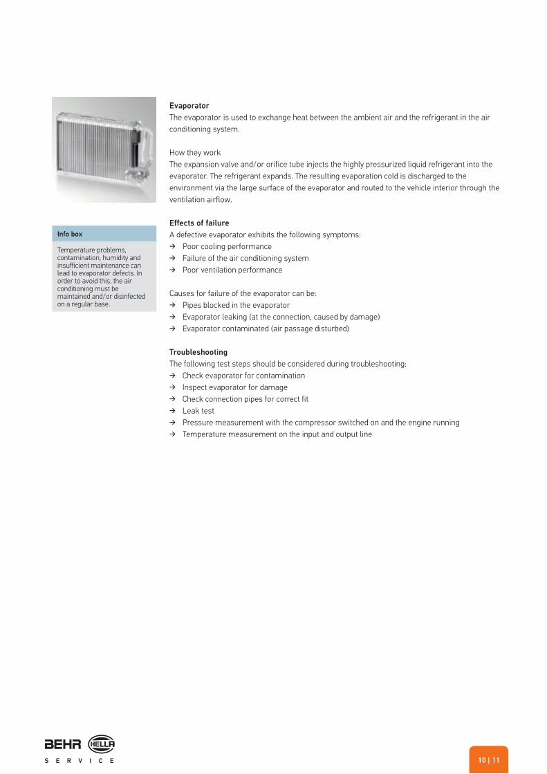
Temperature problems, contamination, humidity and insufficient maintenance can lead to evaporator defects. In order to avoid this, the air conditioning must be maintained and/or disinfected on a regular base.
Evaporator
The evaporator is used to exchange heat between the ambient air and the refrigerant in the air conditioning system.
How they workThe expansion valve and/or orifice tube injects the highly pressurized liquid refrigerant into the evaporator. The refrigerant expands. The resulting evaporation cold is discharged to the environment via the large surface of the evaporator and routed to the vehicle interior through the ventilation airflow.
Effects of failure
A defective evaporator exhibits the following symptoms: � Poor cooling performance � Failure of the air conditioning system � Poor ventilation performance
Causes for failure of the evaporator can be: � Pipes blocked in the evaporator � Evaporator leaking (at the connection, caused by damage) � Evaporator contaminated (air passage disturbed)
Troubleshooting
The following test steps should be considered during troubleshooting: � Check evaporator for contamination � Inspect evaporator for damage � Check connection pipes for correct fit � Leak test � Pressure measurement with the compressor switched on and the engine running � Temperature measurement on the input and output line

AIR CONDITIONING BASICS
Pressure switches and switches
Pressure switches are responsible for protecting the air conditioning system against damage caused by too high or too low pressures. There are low pressure switches, high pressure switches and trinary switches. The trinary switch comprises the high pressure switch and the low pressure switch and an additional switch contact for the condenser fan.
How they work
The pressure switch (pressure monitor) is normally installed on the high pressure side of the air conditioning system. In the case that the pressure is too high (approx. 26-33 bar) it switches the power supply to the compressor clutch off. If the pressure is reduced (approx. 5 bar), its switches the power supply on again. If the pressure is too low (approx. 2 bar), the power supply is interrupted as well in order to avoid compressor damage due to insufficient lubrication. The third switch contact in the trinary switch controls the electrical condenser fan in order to ensure optimum refrigeration condensation in the condenser.
Effects of failure
A defective or failing pressure switch can manifest itself as follows: � Insufficient cooling performance � Frequent switching on and off of the compressor clutch
Air conditioning system without function. There are a number of possible causes of failure: � Contact fault at electrical connections � Contaminations in the system � Damage to the housing caused by vibrations or accidents
Troubleshooting
Test steps for fault diagnostics: � Visual inspection � Check connector block for correct fit � Inspect component for damage � Pressure measurement with the compressor switched on and the engine running � Component test in the disassembled condition with nitrogen gas cylinder, pressure reducer and
multimeter
Info box
Pressure switches may fail due to contacting problems or contaminations. Regular system maintenance prevents failures. Further air conditioning system switches, such as On/Off switches complete the program.

| 1312
Ventilation fan
The ventilation fan is used to ventilate the passenger car. It ensures clear visibility and a pleasant interior climate. Major pre-requisites for safe and comfortable driving.
Info box
Failure of the fan results in an uncomfortable interior climate, which has a negative impact on the driver’s concentration. This represents a significant reduction in safety. Lack of ventilation can also cause the windshield to mist up. Vision limited by misted up windows is a major safety risk.
Fittings and tubes
Fittings and tubes connect the single components carrying refrigerant. The fittings are pressed onto the tube end using a special tool. This tool is available in a variety of designs.
Condenser fan
The condenser fan helps to ensure the optimal liquefaction of the refrigerant no matter what operating state the vehicle is in. It is mounted upstream or downstream of the condenser and/or engine cooling system as an additional or combination fan.
Info box
Condenser fans may fail due to electrical or mechanical damage. As a result, the refrigerant is not sufficiently liquefied anymore. The air conditioning system performance is reduced.

AIR CONDITIONING BASICS
REPAIR AND SERVICE
Safety information/handling of refrigerant
� Always wear safety glasses and safety gloves!Under normal atmospheric pressure and at ambient temperatures liquid refrigerant evaporates so suddenly that contact with skin or eyes may cause frost damage to the tissue (risk of blinding).
� In the case of contact, rinse the affected locations with plenty of cold water. Do not rub. Immediately seek medical attention!
� When working on the refrigerant circuit the work-place must be well ventilated. Inhalation of high concentrations of gaseous refrigerant causes dizziness and danger of suffocation. Work on the refrigerant circuit may not be performed from working pits. As gaseous refrigerant is heavier than air, it can there accumulate in high concentrations.
� Do not smoke!Cigarette embers can break down refrigerant into toxic substances.
� Refrigerant must not contact open fire or hot metal. Deadly gases may be generated.
� Never allow refrigerant to escape into the atmosphere. If the refrigerant container or the air conditioning system are opened, the content discharges under high pressure. The pressure amount depends on the temperature. The higher the temperature is, the higher is the pressure.
� Avoid any head impact on components of the air conditioning system. After paintwork, vehicles must not be heated above 75 °C (drying furnace). Otherwise, the air conditioning system must be drained first.
� When removing the service tubes from the vehicle, the connections must not be pointed towards your body. Refrigerant residues may leak.
� When cleaning the vehicle, the steam-jet cleaner must not be directly pointed onto parts of the air conditioning system.
� Never change the factory setting of the adjusting screw on the expansion valve.

| 1514
REMOVAL AND INSTALLATION
INSTRUCTIONS
Air conditioning system
Prior to removal and/or installation of the spare part it must be verified that connections, fixings and other installation-relevant properties are identical.
When replacing components, always use new O-rings suitable for the refrigerant.
The compressor oil has a strong hygroscopic effect. Thus, the system must be kept closed if possible and/or the oil is to be filled shortly prior to closing the refrigerant circuit only.
Prior to the installation, O-rings and seals are to be greased with refrigerant oil or special lubricants in order to facilitate installation. No other greases or silicone spray may be used as this results in immediate contamination of the new refrigerant.
For every opening of the refrigerant circuit the dryer must be replaced due to its strong hygroscopic effect. If dryer or accumulator are not replaced on a regular base, the filter pad may decompose and silicate particles may be distributed in the entire system and cause severe damage.
The system connections should never remain open for an extended period of time, but should be immediately closed using caps or plugs. Otherwise, liquid would be entered together with air into the system.
In order to avoid damage to connection pipes and/or components, always use two wrenches when loosening and fastening the connections.
When routing tubes and cables make sure that no damage is possible caused by vehicles edges or other moving components.
When replacing a component of the air conditioning system, the correct oil quantity in the system is to be ensured. Oil must be refilled or drained as needed.
Prior to refilling the system, it must be checked for leaktightness. Next, the system is to be sufficiently evacuated (approx. 30 minutes) in order to ensure that all humidity is removed from the system.
O-ring set Pressure gaugeFilter dryer

AIR CONDITIONING BASICS
After filling the refrigerant quantity specified by the vehiclemanufacturer, the system is to be checker for proper functionand leak-tightness (electronic leak indicator). At the same time,the high and low pressure values must be observed usingpressure manometers and compared with the specified values.Compare the outflow temperature on the centre vent with thevalues specified by the manufacturer.
After the service connections are fitted with protective caps, themaintenance due date is to be indicated on an adhesive servicelabel on the front cross member.
Information regarding the installation of air conditioning
system compressors
Make sure that all contaminations and foreign substances are removed from the refrigerant circuit. For this purpose, the system is to be flushed prior to installing the new compressor. Depending on the level of contamination, refrigerant R134a or a special flushing solution is suitable for flushing. Compressors, dryers (accumulators), expansion valves and/or orifice tubes cannot be flushed. As it must always be assumed and cannot be
ruled out that the system is contaminated (abrasion, swarf) when a compressor is defective, the system must always be flushed when this component is replaced. Make sure that no flushing solution residues remain in the system. Dry the refrigeration circuit using nitrogen as needed.
Replace the filter dryer or accumulator and the expansion valveor orifice tube.
PAO-Oil 68Electronic leak indicator

| 1716
As one and the same compressor can potentially be used for different vehicles or systems, the oil filling quantity and viscosity must be checked and/or corrected according to the manufacturer's specifications before installing the compressor. All the oil must be siphoned off and collected. The compressor must then be newly filled with the entire oil quantity specified by the vehicle manufacturer (system oil quantity).
The compressor must be spun 10 x by hand before being installed to ensure the oil is distributed evenly. When installing the drive belt it must be ensured that it is aligned. Some compressors are designed for so-called "multiple applications". This means that they can be installed in different vehicles. Except the number of grooves on the magnetic clutch, there is 100% agreement with the "old part".
After compressor installation and new filling of the refrigerant circuit, the engine should first be started and operated for several minutes at idling speed.
Further specifications (instruction leaflets, manufacturer's specifications, run-in specifications) are to be separately observed.

AIR CONDITIONING BASICS
FAULT DIAGNOSTICS
Testing the cooling capacity
In addition to test and special tools, every garage requires respective specialist knowledge, which can be acquired by
1. Start the engine. Switch through the ventilation stages.
Ventilation functioning?
5. Operate the system at maximum cooling performance and
medium ventilation stage for several minutes. Air outflow
temperature at the centre vent 3-8 °C.
7. Check low pressure (LD) and high pressure (HD) at 2000
- 2500 rpm: LD: 0.5 - 3.0 bar; HD: 6.0 - 25.0 bar; for power-
regulated compressors: LD: approx. 2 bar, constant
3. Temperature to maximum cooling
Magnetic clutch activated?
2.
� Check fuse � Check relays switches, wiring of all
components
6.
If the outflow temperature is too hot: � Heating switched off? � Interior filter OK? � Check temperature switch/ sensor,
thermostat (if available) � Check venting flaps, heating valves,
condenser ventilation
8.
See table Troubleshooting
4.
� Check wiring/electrical connections, power supply (+/-)
� Check temperature switch/ sensor, pressure switch
� Refrigerant filling level not correct
Yes Yes
Yes
Yes
Proceed to 5. Air conditioning
OK
No No
No
No
training. This applies in particular to air conditioning systems. Due to the different systems, these instructions can merely be used as guideline.

| 1918
Correct evaluation of the pressure manometer display is particularly important. Here are some examples:
Air conditioning systems with expansion valve
Low pressure High pressure Outflow temperature at the centre vent
Possible causes
hoch high higher, up to ambient temperature
engine overheated, condenser contaminated, condenser fan defective-incorrect direction of rotation, system overfilled
normal to occasionally low high, occasionally higher, possibly fluctuating expansion valve stuck, occasionally closed
normal high slightly higher filter dryer aged, condenser contaminated
hoch normal to high higher depending on bottleneck line from condenser to expansion valve narrowed
normal normal higher too much refrigerant oil in the system
normal, but inconsistent normal, but inconsistent higher humidity in the system, defective expansion valve
fluctuating fluctuating fluctuating expansion valve or compressor defective
normal to low normal to low higher evaporator contaminated, lack of refrigerant
high low higher, almost ambient temperature
expansion valve stuck in opened position, compressor defective
low low higher, up to ambient temperature
lack of refrigerant
low pressure and high pressure are the same
low pressure and high pressure are the same
ambient temperature lack of refrigerant, compressordefective, fault in the electricalsystem
Air conditioning system with orifice tube
Low pressure High pressure Outflow temperature at the centre vent
Possible causes
high high higher, up to ambient temperature
engine overheated, condenser contaminated, condenser fan defective-incorrect direction of rotation, system overfilled
normal to high high higher system overfilled, condenser contaminated
normal normal to high fluctuating humidity in the system, orifice tube occasionally blocked
high normal higher orifice tube defective (cross-section)
normal normal higher too much refrigerant oil in the system
normal to low normal to low higher lack of refrigerant
low pressure and high pressure are the same
low pressure and high pressure are the same
ambient temperature lack of refrigerant, compressordefective, fault in the electricalsystem

COMPRESSOR
REMOVAL/INSTALLATION AND
TROUBLESHOOTING FOR AIR
CONDITIONING COMPRESSORSGeneral
The air conditioning compressor is driven by the vehicle engine via a ribbed or V-ribbed belt. It compresses and transports the refrigerant in the system. There are different compressor designs available.
How they work
The refrigerant is sucked in as a gas under low pressure and low temperature from the evaporator; it is then compressed and forwarded to the condenser as a gas under high temperature and high pressure.
Effects of failure
A damaged or failed compressor can manifest itself as follows: � Loss of sealing � Development of noise � Insufficient or no cooling performance � Fault code is stored (automatic air conditioning)
Caution!
Before installing a new compressor, you must check the oil quantity and the viscosity according to the manufacturer's instructions!
Screw connections Gear Oil filler cap
Housing
Driving shaft
Swash platePiston
Seal
Cylinder head
Suction pressure valve
| 2120
There are a number of possible causes of failure:
� Bearing damage caused by a defective tensioner or by wear
� Loss of sealing of the compressor shaft or of the housing � Mechanical damage to the compressor housing � Contact (electrical connections) � Lack of refrigerant oil � Lack of refrigerant � Solids (e.g. swarf) � Humidity (corrosion etc.)
Troubleshooting
Function test and pressure measurement of the system: � Does the compressor switch on, is the connector plug
securely in place, is there voltage? � Check that the drive belt is positioned correctly, undamaged,
and that there is tension. � Check visually for loss of sealing. � Check that refrigerant tubes are securely in place. � Compare the pressures on the high and low pressure sides. � Read out the fault memory.
Attention must always be paid to the following:
The entire air conditioning system must be cleaned to 100 % and the consumables must be replaced when the compressor is replaced.
COMPRESSOR
OK
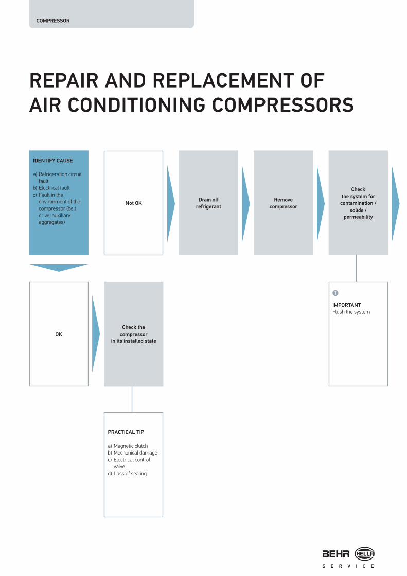
REPAIR AND REPLACEMENT OF
AIR CONDITIONING COMPRESSORS
IDENTIFY CAUSE
a) Refrigeration circuitfault
b) Electrical faultc) Fault in the
environment of thecompressor (beltdrive, auxiliaryaggregates)
Check the
compressor
in its installed state
PRACTICAL TIP
a) Magnetic clutchb) Mechanical damagec) Electrical control
valved) Loss of sealing
IMPORTANT
Flush the system
Not OKDrain off
refrigerant
Remove
compressor
Check
the system for
contamination /
solids /
permeability

| 2322
IMPORTANT
Check oil quantitybefore installation→ Replenish if
necessary
IMPORTANT
Filling the airconditioning systemRun-in specification
PRACTICAL TIP
Pour in leak detector
PRACTICAL TIP
Install filter screen into the suction line on the compressor prior to installation as needed
PRACTICAL TIP
Please note
manufacturer’s
specifications:
a) Vacuum timeb) Refrigerant filling
level
See the following
page
Install a new or
repaired compressor
Replace the
expansion / orifice
tube and filter dryer /
accumulator
Using the service
station
1.Generate a vacuum
2. Conduct a leak test3. Fill with refrigerant
1. System pressure
test
2. Leak test
3. System check
Attach service label
Conduct test drive
Document completed
work

50%10%
20%
10%10%
COMPRESSOR
Thorough flushing
Dirt particles in the air conditioning circuit can only be removed by flushing the entire system thoroughly. Refrigerant R134a or a special flushing solution is suitable for flushing, depending on the level of contamination. Compressors, dryers (accumulators), expansion valves and orifice tubes cannot be flushed. As it must always be assumed and cannot be ruled out that the system is contaminated (abrasion, swarf) when a compressor is defective, the system must always be flushed when this component is replaced.
Refrigerant oils
Observe manufacturer's specifications and enclosed leaflet /viscosity.
1. Distribution of the oil.There is refrigerant oil in every component of the air conditioning system. The oil is removed with the replaced component during repairs. It is therefore essential to refill the appropriate quantity of oil. The graphic below shows the average distribution of the quantities of oil within the system.
2. Observe the quantity and specification of the oil.Before installing a new compressor or refilling refrigerant oil, the oil quantity and the viscosity according to the vehicle manufacturer’s specifications must always be observed.
3. Correct quantity of system oil in the compressor.As one and the same compressor can potentially be used for different vehicles or systems, the oil filling quantity and viscosity must be checked and/or corrected according to the manufacturer's specifications before installing the compressor. All the oil must be drained off and collected. The compressor must then be refilled with the entire oil quantity specified by the vehicle manufacturer (system oil quantity). To ensure the oil is evenly distributed, the compressor has to be spun 10 x by hand before installation. This complies with the instructions of the compressor manufacturer, Sanden – the instructions of other vehicle manufacturers must be followed in each case.
Compressor filter screens
Every air conditioning system must be flushed when the compressor is replaced in order to remove contamination and foreign substances from the system. If there is still contamination in the circuit despite flushing, damage can be prevented by the use of filter screens in the suction line.
Compressor
Pipes / tubes
Evaporator
Condenser
Filter dryer/accumulator
General: Average distribution of oil quantity in the refrigerant circuit

| 2524
Important!
Replace all O-rings and wet with refrigerant oil before installation.
Filling the air conditioning system with refrigerant
Run-in specification for the compressor:
� Only fill the refrigerant using the air conditioning service station via the high pressure side service connection to prevent pressure surges of refrigerant in the compressor.
� Only the correct refrigerant in the quantity / specification defined by the vehicle manufacturer may be used.
� Set the air distribution to “centre vents” and open all centre vents.
� Set the switch for the fresh air fan to medium. � Set the temperature to maximum cooling. � Start the engine (without running the air conditioning) and
run the engine for at least 2 minutes without interruption at idle speed.
� While at idle speed, turn on the air conditioning for approx. 10 seconds, then turn off the air conditioning for approx. 10 seconds. Repeat this procedure at least 5 times.
� Carry out a system check.
Leak detectorl
Compressor damage is caused by lack of refrigerant. It is therefore recommended that air conditioning maintenance is carried out regularly and that dye is added to the system, if necessary.

COMPRESSOR
COMPRESSOR DAMAGE
Fig. 1 Fig. 2
After correction of a leak or air conditioning service the air
conditioning system does not function anymore.
Case:
After the replacement of air conditioning components as well as after normal air conditioning service it happens from time to time that the air conditioning system does not function properly anymore - either immediately or shortly after the work conducted.
What is the customer complaining about?
The customer originally brings the vehicle into the garage claiming that "the air conditioning system does not cool properly anymore or "the air conditioning system does not cool at all anymore".
What does the garage do?
In such cases, the filling level of the refrigerant circuit is usuallychecked first. It is often found that the refrigerant amount in thesystem is insufficient. Depending on the system type, up to 10 %of refrigerant can diffuse from the air conditioning system withinone year. However, before the system can be newly filled withrefrigerant, it must be determined, whether the lack ofrefrigerant is caused by "natural loss" or a leak. If a leak issuspected, the system may not simply be filled with refrigerantagain. First, a search for leaks must be performed, where the air
conditioning system is e.g. filled with forming gas and testedusing an electronic leak indicator. Depending on the result, eitherthe leaking component (figure 1) of the refrigerant circuit isreplaced, or the filter dryer element only. Next, the system isproperly evacuated and filled with refrigerant and oil according tomanufacturer's specifications.
When the air conditioning system is started up again, it may occur that the compressor output is gone. If the pressure values are compared at the service station it can be observed that the values on the high pressure and low pressure side are almost identical (figure 2). It can be suspected that either the flow in the refrigerant circuit is insufficient (e.g. at the expansion valve) or that the compressor is defective. Strangely enough, there are cases, where the high pressure and low pressure values during the initial air conditioning system inspection are within the normal range, and merely the refrigerant filling level is too low; and where problems only occur after proper new filling of the air conditioning system. Evacuating and new filling can loosen dirt particles or metal abrasion, which can then deposit in the control valve (figure 3) of the compressor or in the expansion valve/orifice tube (figure 4) and cause malfunctions. This can particularly occur if the filter dryer was aged or the system was "under-filled".

| 2726
Fig. 3 Fig. 5Fig. 4
What needs to be done?
In the case of problems the compressor should be removed and the oil should be drained. If a "greyish discoloration" (grey-green or grey-yellow if dye is used) of the oil can be detected, where fine metal particles (figure 5) are present as well, the refrigerant circuit must be properly flushed due to the foreign particles, the expansion valve and the filter dryer must be replaced, and the refrigerant circuit must be evacuated according to the specifications and newly filled with refrigerant and oil. After that, the system should function again without problems.
Is the customer sufficiently informed?
As the garage provided the customer merely with an estimate for the search for leaks and possibly for replacing the leaking component or the air conditioning service only, they may face arguments with the customer. The customer is often not ready to pay for the significant additional costs for e.g. replacing the compressor or flushing the system. For this reason, a detailed discussion with the customer, where the technical issue and risks are presented, is especially important.
What is the cause for the compressor failure?
The compressor contains the only moving components of the refrigerant circuit, and must respectively be sufficiently supplied with oil. Another task of oil in the refrigerant circuit is compressor cooling in order to avoid overheating. If a compressor is operated with an insufficient amount of refrigerant for an extended period of time (e.g. due to a leak), this results in insufficient heat dissipation and lubrication of the compressor components, as the oil must be transported together with the refrigerant through the air conditioning system. Due to the excessive operating stress on the compressor components, metal abrasion is generated on the components, which may cause partial or complete blockage of the control valve located on the inside. The control valve blockage results in
the compressor not properly working anymore. This damage can only be corrected by professional replacement of the compressor, which also includes flushing of the system. By the way, insufficient lubrication results in damage in all compressor designs. However, power-controlled compressors react particularly sensitively to insufficient refrigerant and/or oil.
Information for garages and parties accepting repairs
If the customer brings a vehicle for repair due to insufficient cooling capacity, he should be informed about a possibly required replacement of the compressor. The reason for that is that a possibly insufficient refrigerant quantity and the related lack of lubrication can cause pre-existing damage. In the case of doubt, the compressor must always be removed. If the oil is contaminated, the system must be flushed prior to replacing the compressor. If the customer request a deviating approach, the garage should record this on the bill and/or to have the customer confirm his request in writing. This Technical Information was prepared in collaboration with compressor manufacturer Sanden and is applicable to all compressor manufacturers and compressor types currently known in the market.
COMPRESSOR
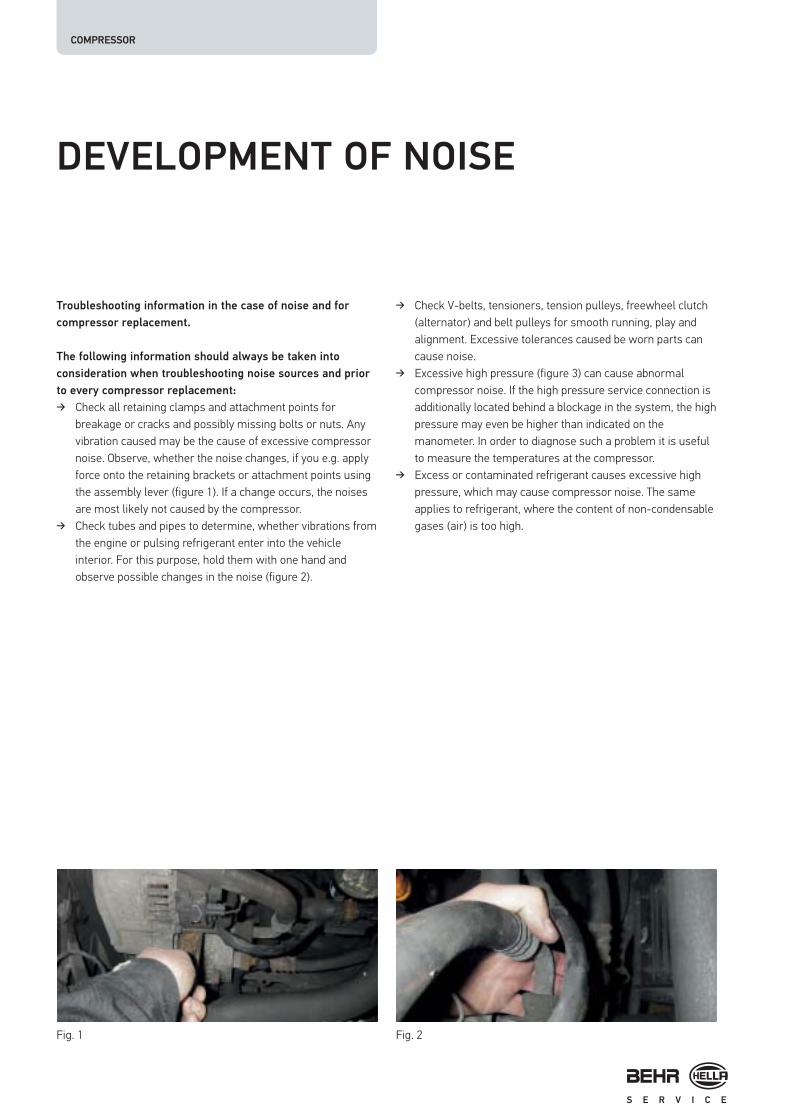
DEVELOPMENT OF NOISE
Troubleshooting information in the case of noise and for
compressor replacement.
The following information should always be taken into
consideration when troubleshooting noise sources and prior
to every compressor replacement:
� Check all retaining clamps and attachment points for breakage or cracks and possibly missing bolts or nuts. Any vibration caused may be the cause of excessive compressor noise. Observe, whether the noise changes, if you e.g. apply force onto the retaining brackets or attachment points using the assembly lever (figure 1). If a change occurs, the noises are most likely not caused by the compressor.
� Check tubes and pipes to determine, whether vibrations from the engine or pulsing refrigerant enter into the vehicle interior. For this purpose, hold them with one hand and observe possible changes in the noise (figure 2).
� Check V-belts, tensioners, tension pulleys, freewheel clutch (alternator) and belt pulleys for smooth running, play and alignment. Excessive tolerances caused be worn parts can cause noise.
� Excessive high pressure (figure 3) can cause abnormal compressor noise. If the high pressure service connection is additionally located behind a blockage in the system, the high pressure may even be higher than indicated on the manometer. In order to diagnose such a problem it is useful to measure the temperatures at the compressor.
� Excess or contaminated refrigerant causes excessive high pressure, which may cause compressor noise. The same applies to refrigerant, where the content of non-condensable gases (air) is too high.
Fig. 1 Fig. 2

| 2928
Fig. 3 Fig. 4 Fig. 5
� The condenser can also be considered as cause of unusual noise. If insufficient air is routed through the condenser, the refrigerant cannot sufficiently condensate and the high pressure increases excessively. This can result in abnormal noise development. Check as well, whether the fan(s) transport(s) sufficient air through the condenser. Check the condenser and radiator fins for possible contaminations as well (figure 4).
� Often noise can be caused by contaminated expansion valves (figure 5) or orifice tubes. This can e.g. by caused by contaminations in the form of metal abrasion. This causes a reduction of the refrigerant flow and excessive high pressure occurs. "Defective" expansion valves can e.g. generate diverse "buzzing, whistling or droning noise", which can be well perceived in the vehicle interior.

COMPRESSOR
COMPRESSORS WITHOUT
MAGNETIC CLUTCH
General
Since a few years so-called "clutch-free", externally controllable, variable compressors have been used. All major compressor manufacturers use different basic types. Here the types most commonly used in the market are listed: Denso with types 6SEU and 7SEU; Sanden, with types PXE 13 and PXE 16. Delphi/Harrison offers a model with the CVC7 series, which is very similar to the V5 compressor design. This generation of compressors is used by almost all vehicle manufacturers (Audi, BMW, Citroen, Seat, VW, Opel, ...). Externally controlled means that the displacement volume of the compressor is determined using an integrated control valve controlled by the air conditioning control unit depending on different system parameters, such as exterior temperature, requested temperature, high pressure, low pressure, RPM speed and engine load. "Clutch-free" means that the compressor is not equipped with an electromagnetic clutch. This means that the compressor is permanently driven via a belt pulley and that it also operates, when the air conditioning system is switched off. However, its output is reduced to a small percentage value.
Function
The belt pulley unit of the compressor consists e.g. of a driven plate and the actual belt pulley (drawing). The driven plate consists of a rubber element and establishes the connection between belt pulley and compressor shaft. She acts as vibration damper and protects the compressor and/or other driven aggregates against overload and/or damage. If the compressor should e.g. block, the transmitted forces between belt pulley and driven plate significantly increase in the area of the rubber element.
Depending on compressor manufacturer and/or compressortype, the connection is interrupted due to deformation of therubber element or by triggering the "overload protection". In thiscase the belt pulley just moves along without function. As aresult, damage to the belt and/or other aggregates driven by thebelt is prevented.
Fig. 1 Fig. 2Function example
Belt pulley
Rubber element
Driven plate

| 3130
The control valve (figure 1) is arranged in the compressor and receives its PWM signals from the air conditioning control unit. The current, which is relayed from the control unit to the control valve and which determines the compressor output, can be displayed as measured value block using a diagnostic device. Compressors without clutch are equipped with a safety valve (figure 2), which should protect the compressor and all other components of the air conditioning system against too high pressure. The valve mostly triggers between 35 and 45 bar (depending on the compressor manufacturer). The valve opens only, until the overpressure is released. Next, it closes again in order to not release the entire refrigerant quantity into the atmosphere. If the foil of the valve is damaged, it can be assumed that the valve did "trigger".
Fig. 3 Fig. 4 Fig. 5
Diagnostics
The belt pulleys and their rubber elements designed as "overload protection" are designed differently depending on the compressor type. Depending on the type, there are different ways to detect, whether the "overload protection" was triggered:
1. Rubber abrasion is visible on the inside of the belt pulley(figure 3). The compressor shaft is not driven anymore. If thecompressor can be easily turned, belt pulley and/or rubberelement can be replaced.
2. The overload protection triggered the driven plate (figure 4).Driven plate and/or rubber element can be replacedindividually. Prerequisite: The compressor can be easilyrotated.
3. A triggered speed limiter can visually not necessarily bedetected. In order to check, whether the limiter triggered, thecompressor shaft must be secured using a suitable tool (figure5) and the belt pulley must be turned counterclockwise at thesame time. If the belt pulley can be turned counterclockwise,the limiter triggered and the compressor must be replaced. Inthe case of Sanden PXE 13 and PXE 16 compressor types, thespeed limiter cannot be replaced.

–9.80 401.0 HzRMSU~
A AHOLD
Probe 10:1500µs Trig: AA 5 U
B
A
C
–7.80 401.1 HzRMSU~
A AHOLD
Probe 10:1500µs Trig: AA 5 U
A
A
COMPRESSOR
In the case of the Audi A3 and the lowest temperature setting,the maximum current relayed by the control unit to the controlvalve amounts to approx. 0.65 A. In this case the compressorreaches its maximum output. In closed-loop operation a meancurrent of 0.3 A flows. However, the problem in the case of newervehicles is that diagnostics outside the engine managementrange is not possible yet using many test devices. Ideally, anoscilloscope should be used. Using suitable probe tips, the PWMsignal at the plug connector of the compressor can be recorded.The oscilloscope should be adjusted to 5 V/Div and 0.5 ms/Div.Now, the different operating modes can be illustrated on theoscilloscope's screen, while the engine is running. At the lowesttemperature setting ("Lo"), a square-wave signal with a dutycycle of approx. 75 % can be seen (figure 7). The duty cycleresults from the a ratio between pulse width -B- and signaldistance -C- (in this case, 75 % on-period and 25 % off-period).
At the same time, the amount of the onboard electrical systemvoltage (approx. 13.5 V) can be read out based on the Voltdivisions (A=5 V). The voltage value shown (9.8 V) is merely amean value. The pulse width depends on the requested coolingcapacity and the onboard electrical system voltage. The currentfrom the control unit to the control valve is "regulated" across thedistance of the -B- range. Depending on the settings of theoperating unit and environmental influences (e.g. exteriortemperature), the pulse width of the square-wave signal ischanged such and/or the control valve actuated that thecompressor output necessary to achieve the requested
temperature is obtained. Figure 8 shows, how the compressor isregulated down for temperature setting "High". Figure 9 wasrecorded during "Econ" operation (compressor off) and shows nosignal. Based on this method it can be determined, to whatextent the signal is changed by the control unit. If the signalchange is plausible, however the outlet air temperature and/orthe interior temperature does not change, a compressor defectis likely.
Furthermore, diagnostic devices are available in the market, using which a PWM signal with different pulse duration can be generated. This way it can be determined, whether an actuation of the compressor results in a change in the refrigerant pressure. Based on this it can be determined, whether the compressor still functions without problems.
A function test using PWM signal can also be performed using a function (waveform) generator (figure 10). However, for this purpose it is imperatively necessary to connect a "load" to the control unit side of the air conditioning system, which corresponds to the load of an electronic control valve. Otherwise, the control unit detects a fault in the system and stores it in the fault memory. This can lead to malfunctions and/or a system failure. In this case the fault memory must be read out and cleared using a diagnostic device.
Fig. 7 Fig. 8

| 3332
–0.10 ---- HzRMSU~
A AHOLD
Probe 10:1500µs Trig: AA 5 U
A A
In connection with noise and other problems of the air conditioning system, defective compressors are again and again prematurely claimed. In many cases it turns out that the compressor is OK or that the defect is not caused by the compressor. For this reason, all components of the system should always be considered during troubleshooting. Noise cannot only be caused by the compressor, but also by its fixing, the drive, the expansion valve or by the pipes. An incorrect refrigerant quantity can cause diverse noises as well.
Beyond that, the oil provides important information
regarding possible damage:
� If the oil in the compressor or in the systems assumes a red colour, this might be caused by too much humidity.
� Black oil indicates a defective compressor. � Silver-grey oil should be tested for metal filings. The greyish
discoloration indicates metal abrasion.
As the system oil quantities are becoming smaller (partly 80 ml only), monitoring of and compliance with the oil quantity (e.g. during air conditioning service and component replacement) is of highest importance.
A compressor without clutch is only possible to a limited extent. In any case, a repair must be conducted using suitable tools and repair information.
The evaluation of system pressures is of special importance during diagnostics. In this context, the target values of the vehicle manufacturer should be considered. This also applies to the outlet air temperature.
Fig. 9 Fig. 10

COMPRESSOR/MAINTENANCE AND REPAIRS
Guidelines for the evaluation of system pressures can be obtained from the table below:
System pressure evaluation
High pressure Low pressure Symptoms Possible cause Possible remedies
Normal Normal � Out-flowing air is not cold � Too much oil in the air conditioning system � Air or humidity in the in the air conditioning system
� Exhaust and flush the air conditioning system and refill with oil and refrigerant � Exhaust air conditioning system, replace dryer and refill
High High � Low pressure line colder than evaporator � High pressure decreases, if the condenser is cooled with water � High pressure and low pressure equalize as soon as the compressor is switched off and pulse as soon as the compressor is switched on
� Expansion valve openedtoo far � Too much refrigerant in the system � Condenser contaminated/blocked � Fan problems � Problem with compressor (exhaust valve/sealing)
� Replace expansion valve � Exhaust and refill the air conditioning system � Check the condenser, clean/replace � Check the fan � Check the compressor, replace as needed
Low Low � Out-flowing air is not cold � Suction line is colder than the evaporator
� Not enough refrigerant in the system � Blockage on the suction side
� Exhaust and refill the air conditioning system � Check pipes and connections, replace as needed
High Low � Ice generation on the liquid line � Ice generation on the dryer
� Line/dryer blocked � Check dryer/line, replace as needed
| 3534
FLUSHING THE AIR CONDITIONING
SYSTEM
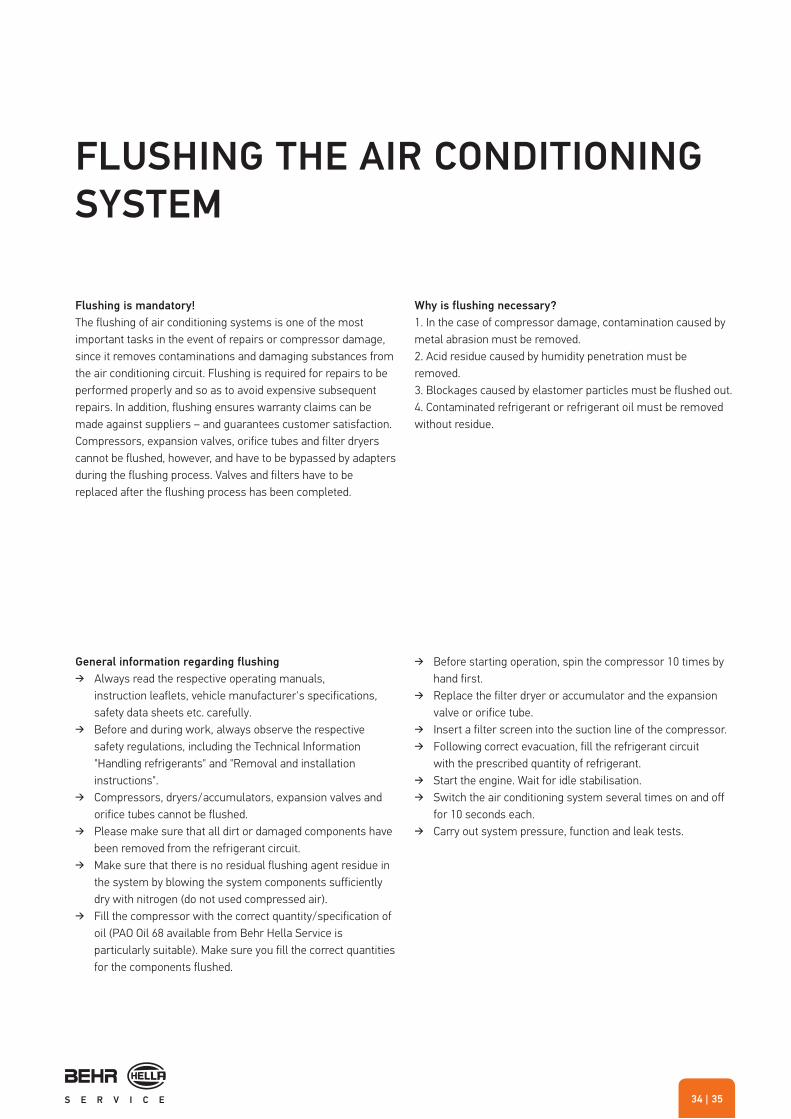
Flushing is mandatory!
The flushing of air conditioning systems is one of the most important tasks in the event of repairs or compressor damage, since it removes contaminations and damaging substances from the air conditioning circuit. Flushing is required for repairs to be performed properly and so as to avoid expensive subsequent repairs. In addition, flushing ensures warranty claims can be made against suppliers – and guarantees customer satisfaction. Compressors, expansion valves, orifice tubes and filter dryers cannot be flushed, however, and have to be bypassed by adapters during the flushing process. Valves and filters have to be replaced after the flushing process has been completed.
Why is flushing necessary?
1. In the case of compressor damage, contamination caused bymetal abrasion must be removed.2. Acid residue caused by humidity penetration must beremoved.3. Blockages caused by elastomer particles must be flushed out.4. Contaminated refrigerant or refrigerant oil must be removedwithout residue.
General information regarding flushing
� Always read the respective operating manuals, instruction leaflets, vehicle manufacturer's specifications, safety data sheets etc. carefully.
� Before and during work, always observe the respective safety regulations, including the Technical Information "Handling refrigerants" and "Removal and installation instructions".
� Compressors, dryers/accumulators, expansion valves and orifice tubes cannot be flushed.
� Please make sure that all dirt or damaged components have been removed from the refrigerant circuit.
� Make sure that there is no residual flushing agent residue in the system by blowing the system components sufficiently dry with nitrogen (do not used compressed air).
� Fill the compressor with the correct quantity/specification of oil (PAO Oil 68 available from Behr Hella Service is particularly suitable). Make sure you fill the correct quantities for the components flushed.
� Before starting operation, spin the compressor 10 times by hand first.
� Replace the filter dryer or accumulator and the expansionvalve or orifice tube.
� Insert a filter screen into the suction line of the compressor. � Following correct evacuation, fill the refrigerant circuit
with the prescribed quantity of refrigerant. � Start the engine. Wait for idle stabilisation. � Switch the air conditioning system several times on and off
for 10 seconds each. � Carry out system pressure, function and leak tests.

MAINTENANCE AND REPAIRS
Flushing medium
Refrigerant Flushing liquid
Flushing methodSystem components are flushed with the aid of the air conditioning service unit and an additional flushing unit with filters and adapters (both available separately).
System components are flushed using an additional flushing unit and a chemical solution. Flushing liquid residue needs to be removed with nitrogen and the system needs to be dried with nitrogen.
Advantages
+ No costs for the flushing agent+ No disposal costs for the flushing agent+ Removes oil and loose dirt particlesl+ Method released by various vehicle
manufacturers
+ Removes oil and loose and persistent particles+ Excellent cleaning results
Disadvantages
– Less than optimal cleaning effect in the case of adheringcontaminations
– Filter insert of the flushing unit has to be replaced at regularintervals
– The air conditioning service unit is not available duringthe procedure
– Costs for the flushing agent– Disposal costs for the flushing agent
Air conditioning products
Advantages and disadvantages of the different flushing methods
Air conditioning service unit
Flushing unit Condenser

| 3736
Flushing the air conditioning system and the components
Air conditioning systems are flushed to remove impurities and damaging substances from the refrigerant circuit. The following information has been compiled to provide support for users new to the subject of "flushing air conditioning systems" by answering important points such as:
� Why air conditioning systems need flushing at all � What the term "flushing" means in connection with vehicle
air conditioning � What types of impurities are eliminated by "flushing" or what
effects these kinds of impurities have � Which methods of flushing exist and how they are
used.
Why should a vehicle air conditioning system be flushed at all?
Defective system components (old filter dryers (figure), compressor damage etc.) can lead to dirt particles that are swept along by the refrigerant being distributed in the whole air conditioning system. If, for example, only the compressor is replaced following compressor damage, dirt particles can collect in the new compressor in no time and lead to the destruction of the newly installed system components as well as the expansion valve/orifice tube or multi-flow component – with expensive follow-on repairs the logical consequence. To avoid this, the system must always be flushed out following component
damage that could lead to contamination of the refrigerant circuit through metal filings, rubber abrasion etc.! In the meantime, the process of flushing is also required by many vehicle or compressor manufacturers.
What does the term "flushing" mean in connection with
vehicle air conditioning?
The term "flushing" is used to describe the process of removing impurities or damaging substances from the refrigerant circuit. Flushing is necessary for professional repairs to be carried out, expensive follow-on repairs to be avoided, guarantee claims against suppliers to be upheld and customer satisfaction to be ensured.
Aged filter dryer

MAINTENANCE AND REPAIRS
What types of impurities are eliminated by "flushing" or what
effects do these kinds of impurities have?
� Abrasion when the compressor is damaged:The material particles block expansion valves, orifice tubes or multi-flow components (condenser and evaporator).
� Humidity:Expansion valve and orifice tubes can freeze up. Acids thatmake tubes and O-rings porous can form as the result ofchemical reactions between refrigerants / refrigerant oilsand humidity. System components are damaged bycorrosion.
� Elastomers (rubber):The elastomer particles block expansion valves, orifice tubesor multi-flow components.
� Contaminated refrigerant oil or refrigerant:: Contaminated refrigerant or a mixture of different refrigerantoils can cause acids to form as well. The acids can maketubes and O-rings porous. Further system components canbe damaged by corrosion.
1. Chemical agent (flushing liquid)
The connection pipes or system components must be flushed individually. They are flushed using a chemical agent (flushing liquid) with the aid of a universal adapter on a flushing gun. Following the flushing process, nitrogen must be used to remove the flushing medium residue from the refrigerant circuit and to dry the refrigerant circuit.
Recommendation
Maximum efficiency is achieved by combining the use of flushing liquid and nitrogen. First, even stubborn particles and hardened deposits are eliminated by flushing with flushing liquid. The subsequent blowing out with nitrogen dries the refrigerant circuit and the components again.
Disadvantage
Costs for the chemical cleaning agent and its professional disposal, as well as additional installation costs for removing and replacing pipes and components.
Contaminated oil Flushing with flushing solution
Abrasion with compressor damage
| 3938
2. Refrigerant
When flushing with refrigerant (R134a), the existing air conditioning service station is upgraded with adapter and filter elements in order to flush liquid refrigerant through the refrigerant circuit.
Disadvantage
Only loose dirt particles and oil can be removed from the system. In addition, adaptation panels are required for flushing to be carried out properly. These adaptation panels increase the costs of this method due to the additional installation and removal work involved. The service station is not available for other vehicles during the application.
Note
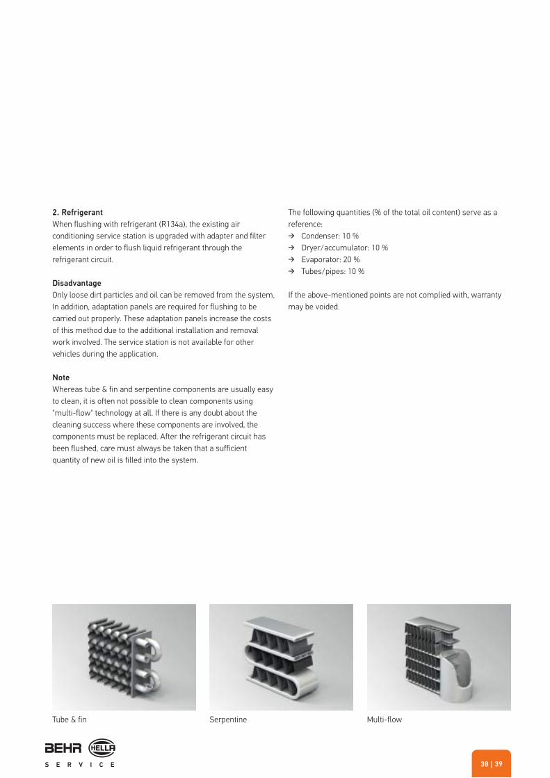
Whereas tube & fin and serpentine components are usually easyto clean, it is often not possible to clean components using"multi-flow" technology at all. If there is any doubt about thecleaning success where these components are involved, thecomponents must be replaced. After the refrigerant circuit hasbeen flushed, care must always be taken that a sufficientquantity of new oil is filled into the system.
The following quantities (% of the total oil content) serve as a reference:
� Condenser: 10 % � Dryer/accumulator: 10 % � Evaporator: 20 % � Tubes/pipes: 10 %
If the above-mentioned points are not complied with, warrantymay be voided.
Tube & fin Serpentine Multi-flow
MAINTENANCE AND REPAIRS
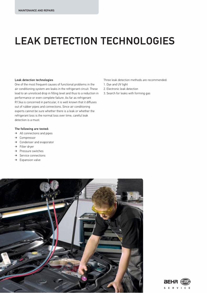
Leak detection technologies
One of the most frequent causes of functional problems in the air conditioning system are leaks in the refrigerant circuit. These lead to an unnoticed drop in filling level and thus to a reduction in performance or even complete failure. As far as refrigerant R134a is concerned in particular, it is well known that it diffuses out of rubber pipes and connections. Since air conditioning experts cannot be sure whether there is a leak or whether the refrigerant loss is the normal loss over time, careful leak detection is a must.
The following are tested:
� All connections and pipes � Compressor � Condenser and evaporator � Filter dryer � Pressure switches � Service connections � Expansion valve
Three leak detection methods are recommended:1. Dye and UV light2. Electronic leak detection3. Search for leaks with forming gas
LEAK DETECTION TECHNOLOGIES

| 4140
Leak detection using dye
Dye
Different methods are used to add dye to the refrigerant (e.g. Spotgun dye, dye cartridges …).
Spotgun/Pro-Shot
The exact amount of dye required is injected using the Spotgun cartridge gun or the Pro-Shot system. Further advantage: Dye can be added when the system is full.
Leak detection lamps
Escaping dye is made visible by the UV light.
Leak detection with electronic tester/with nitrogen/
through foam generation
Electronic leak detection using a leak detectorIndicates leaks through an acoustic signal. It detects halogengases and even detects the tiniest of leaks at points that aredifficult to reach (e.g. evaporator leaks).
Leak detection using a nitrogen set
This tool can be used for leak tests – in addition to its functionfor drying the system. For leak tests, a filling adapter is requiredfor the service connection as well as a tube adapter. The emptiedair conditioning system is filled with nitrogen (maximum 12 bar).It is then observed over an extended period of time (e.g. 5-10 min), whether the pressure remains constant. Leaks aredetected via a "hissing" sound. Otherwise, it may be sensible tomake the leaky spot visible using leak detection agent. The leakdetection agent is sprayed on from the outside. It forms foam atthe point of the leak. Using this method, larger leaks at wellaccessible locations can be detected only.
Leak detection using a forming gas leak indicator
To detect leaks, the empty air conditioning system is filled with forming gas, a mixture of 95 % nitrogen and 5 % hydrogen. Using a special electronic leak indicator, the components are checked for leaks. Due to the fact that hydrogen is lighter than air, the sensor needs to be moved slowly above the suspected leak (electrical connections/components). After the end of the leak search, the forming gas can be released into the atmosphere. This leak detection method complies with Article 6, § 3 of the EU Directive 2006/40/EC.

MAINTENANCE AND REPAIRS/TECHNOLOGY TIPS
REPAIR OF PIPES AND TUBES
LOKRING pipe connection technology
LOKRING is a fast and extremely profitable repair method. Instead of having to order expensive complete pipe systems and wait for deliveries when pipes are defective, the problem can be solved on the spot – often without having to dismantle anything. The LOKRING principle has proved its worth thousands of times over in air conditioning and climate technology.
It stands out thanks to nine processing advantages:
� Simple and quick fitting � Hermetically sealed metal/metal seals that cannot be
detached � Safe connection of pipes made of various materials � No special preparation necessary for the pipes � Handy fitting tools � Large dimensional tolerances allowed � No burring effect in the installation area � No welding, soldering or thread cutting � Eco-friendly and harmless connection technology
Metal with metal line: LOKRING fitting
LOKRING is so airtight that there is no notable drop in pressure and no reduction in flow speed. As a backup, the surfaces of the pipe ends are wetted with LOKPREP sealing fluid. The system is permanently airtight at the LOKRING spots. The pipe connections have been designed for a maximum rated pressure of 50 bar and a testing pressure of 200 bar. They can be used in a temperature range of -50 °C to +150 °C.
Pressing tools for refrigerant fittings
The crimping tool enables the fast and secure connection of tubes and fittings. An ideal pressing system for stationary and mobile use. The hydraulic hand-pump included builds up the pressing effect. A few hand movements are all that are needed to create an immensely strong pressure with a high adjusting range. It often allows tube repairs to be carried out without the tubes having to be removed first. Similar to the LOKRING, the crimp system saves repair-/waiting times and spare part costs. An investment that quickly pays off.
Tube with tube: Crimp fitting

| 4342
REFRIGERANTS R12, R134A,
R1234YF
There are still numerous vehicles in the market with air conditioning systems originally designed for refrigerant R12. 2001 was the official final end for R12 in vehicle air conditionings systems. Starting from that date, R12 system had to be converted during maintenance or repair work. R134a was and is used as replacement refrigerant besides several "drop-in" refrigerants (refrigerant mixtures).
Even today, the conversion from R12 to R134a is still a topic in the area of classic ("Oldtimer") and modern classic ("Youngtimer") cars as well as in several non-EU countries.
In the course of conversion, the system must be checked forleak-tightness. Leaks are to be corrected upfront. Allcomponents should be checked for function and damage. Thefilter dryer is to be replaced. Sealing rings should be replaced. Inaddition, the mineral oil if the R12 system is to be replaced withPAG or PAO oil. In the course of this replacement it isrecommended to flush the air conditioning system. A detaileddescription can be found as Technical Information in "Hella TechWorld".
R134a has a high GWP (global warming potential) of 1430. With the current EC Directive 2006/40/EC it was decided to only use refrigerants with a GWP of less than 150 in the future.
Thus, air conditioning systems of vehicles of class M1(passenger cars, vehicles for passenger transport with amaximum of 8 seats) and of class N1 (commercial vehicles witha gross weight limit of up to 3.5 tons), for which type approval isissued within the EU starting from 01.01.2011, may not be filledanymore with R134a. Starting from 01.01.2017, vehicles filledwith R134a cannot be initially type-approved anymore. However,the use of R134a shall be further permitted for service andmaintenance work on already existing R134a systems. R1234yfwith a GWP of 4 shall be used as new refrigerant. However, theuse of other refrigerants is possible, as long as the GWP valuesis below 150. It remains to be seen to what extent all vehiclemanufacturers will convert to the same or different refrigerants.
Naturally, this shall impact garages and their service personnel.The procurement of new service equipment seems to beunavoidable. Separate measures with respect to storage andhandling of the new refrigerants must certainly be observed.

TECHNOLOGY TIPS
INTERIOR TEMPERATURE SENSORS
Insufficient temperature control due to contaminated sensors
The interior temperature sensor is located in the air flow of a miniature fan (mostly in the operating unit). It provides the temperature of the interior air as resistance value to the control unit. The measured value is compared with the target value.
Nicotine, dust and similar can severely contaminate the sensor (see figure). If the sucked in airflow does not sufficiently reach the sensor, incorrect measurements and malfunctions can occur. In this case, air conditioning / heating control is not properly ensured anymore. This manifests itself in continuous temperature adjustments. In other worlds, it switches between being very cold and very warm in an instant. The sensor can be cleaned using special cleaning agents (e.g. acetone). Dust accumulations can be removed applied minimum compressed air first. In most cases, the control functions properly again after sensor cleaning.

| 4544
SEALANTS
Sealants for air conditioning systems consist of chemical components, which are entered into the air conditioning system in order to seal against smaller leaks on components and O-rings.
Not only refrigerant, but the sealant escapes through the leak as well.
This sealant normally reacts with atmospheric oxygen and humidity, hardens and closes the leak.
The use of sealants is problematic from a different point of view.
According to EC Regulations and Directives, a leaking air conditioning system may not be operated or filled with refrigerant again, without correcting the leak first. An infringement may result in substantial fines.
If sealants are used, refrigerant continues escaping from the leaking air conditioning system, until the sealant is effect (provided that it stops the leak to its full extent). Therefore, the EC law as well as national regulations are violated and
refrigerant is unnecessarily released. The only possible use of sealants would be for preventive purposes - as additive in systems, which are still intact.
If components are pre-damaged or weakened (e.g. due to corrosion), it is just a matter of time until a leak occurs at a different location.
When draining refrigerant from vehicles, which were previously filled with sealant, there is a risk that the sealant reacts inside the air conditioning service unit and thus, causes blockage/damage. For many vehicle, device and component manufacturers the use of sealants puts a warranty claim at risk.
Finally, the use of sealants for a leaking air conditioning system does not represent a legally conform and permanent repair method.

INNOVATIVE AIR CONDITIONING MANAGEMENT
INNOVATIVE AIR CONDITIONING
AND INTERIOR COMFORT
MANAGEMENTWhat are the trends and development directions with respect
to air conditioning systems and interior comfort?
"Multi-zone air conditioning systems" are increasingly becoming the standard. In luxury-class models, air conditioning systems with "humidity management" are already being used, which counteract the production of extremely dry air.
In future, "interior climate management" shall be a part of air conditioning and ventilation systems. This means that with the help or air quality sensors a best possible interior climate is created in connection with air treatment systems.
Electronically controlled compressors shall be the standard in allvehicle classes. These make individual adaptation of power and
thus lower fuel consumption possible. Optimised components,pipes and seals will ensure "refrigerant loss rates" as low aspossible in future.
Customized air conditioning for everybody on every seat:
Customized air conditioning means:
� Individual air conditioning comfort for every seat in the vehicle
� Draught-free, pleasant ventilation � High air quality � Acoustic comfort, as low as possible
noise perception � Simple, clear operation

| 4746
In order to realize these goals, systems such as Physio-
Control® made by Behr and BHTC were developed:
Physio-Control® is a further development of multi-zone air conditioning. The system can selectively record and control the variables (solar irradiation, air humidity, air volume and air temperature) responsible for the comfort in the vehicle interior at defined locations. For this purpose, perfectly aligned subsystems work together.
The technical effort required is enormous. For example, an intelligent sun sensor measures the exact solid angle and solar irradiation intensity relative to the vehicle with the help of hardware and software. Based on that and the recorded vehicle contour, a computation model determines the intensity of radiation on body parts exposed to solar irradiation.
Optimum climate in the vehicle interior also means to continuously keep the windows clear. In order to prevent the windows misting up, the humidity is continuously measured in the area of the windshield. The air is dried via air conditioning system actuation as needed. Another intervention not obvious to vehicle occupants is the so-called humidity management. Here, the air humidity in the interior is kept at a constant level by actuating the air conditioning compressor and the fresh air flap.
So-called comfort ventilation outlets are used as subsystem. These are designed such that the individual outlet vents can be swivelled in a defined manner and continuously adjusted from direct to diffuse air outflow. Using the vents, the exact amount of air volume and type of air is provided to the occupant' bodies, which is perceived as pleasant. For example, this can be a concentrated air flow ("spot") during the cool-down process during the summer or a draught-free, diffuse air flow.
In order to determine the requested air distribution profile, the "Air Volume Control" is used. Here, the air volume exiting from the individual air vents and thus the air velocity is determined. Technically, this is enabled by a simulation software of the entire
air conditioning and air routing system. The Air Volume Control detects for example one-sided air increase or decrease caused e.g. by mechanical closing of the air vent. The control algorithms stored in the software avoid changes in the air conditions on the other side of the vehicle. As a result, air volume and air distribution can be individually adjusted without unnecessary impact on other areas and persons in the vehicle.
Another innovation is the selection of different air conditioningstyles. Hereby, the occupants choose between a spot, moderateor diffuse pre-selection depending on their "comfort type". Thus,cool air is directly blown onto the "sporty fresh" type, while themore "sensitive" type prefers a draught-free environment.

INNOVATIVE AIR CONDITIONING MANAGEMENT
Air quality
In the meantime, the air quality in the vehicle interior is treated in several steps in the case or modern air conditioning systems. This is also referred to as "comfort steps". It starts with filtering of fresh and recirculated air. This is realised by means of a nitrogen oxide sensor system. A NOx or air quality sensor determines the share of pollutants on the sucked in fresh air, which is considered in an automatic fresh air/ recirculated air control. In this context, filtering using activated carbon is increasingly gaining on importance. The evaporator surface should be structured such that no odour generation caused by microorganisms can occur. For this purpose, Behr developed a special coating: Behr-Oxal®. This is an environmental coating technology, which generates a corrosion-resistant and hydrophilic aluminium surface without toxic or aggressive chemicals. As a result, the condensate is very well drained and the evaporator surface dries very quickly.
The measures mentioned above ensure neutralisation of contaminations and odours. For further comfort increase, an oxygen ioniser can be used, which cleans bacteria and germs from the air and maintains a freshness effect. In addition, a perfume atomizer can be used, which adds certain scents to the air in the vehicle interior.
Ergonomics
It has been shown that operating an air conditioning system still distracts the driver too long from traffic events and that the air conditioning system is partly incorrectly operated.
| 4948
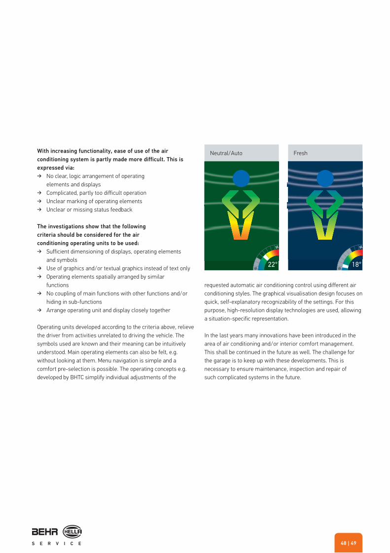
22° 18°
With increasing functionality, ease of use of the air
conditioning system is partly made more difficult. This is
expressed via:
� No clear, logic arrangement of operating elements and displays
� Complicated, partly too difficult operation � Unclear marking of operating elements � Unclear or missing status feedback
The investigations show that the following
criteria should be considered for the air
conditioning operating units to be used:
� Sufficient dimensioning of displays, operating elements and symbols
� Use of graphics and/or textual graphics instead of text only � Operating elements spatially arranged by similar
functions � No coupling of main functions with other functions and/or
hiding in sub-functions � Arrange operating unit and display closely together
Operating units developed according to the criteria above, relieve the driver from activities unrelated to driving the vehicle. The symbols used are known and their meaning can be intuitively understood. Main operating elements can also be felt, e.g. without looking at them. Menu navigation is simple and a comfort pre-selection is possible. The operating concepts e.g. developed by BHTC simplify individual adjustments of the
requested automatic air conditioning control using different air conditioning styles. The graphical visualisation design focuses on quick, self-explanatory recognizability of the settings. For this purpose, high-resolution display technologies are used, allowing a situation-specific representation.
In the last years many innovations have been introduced in the area of air conditioning and/or interior comfort management. This shall be continued in the future as well. The challenge for the garage is to keep up with these developments. This is necessary to ensure maintenance, inspection and repair of such complicated systems in the future.
Neutral/Auto Fresh

INNOVATIVE AIR CONDITIONING MANAGEMENT
THERMAL MANAGEMENT
IN HYBRID VEHICLES
Do not work on live high-voltage components! Always
observe the warning signs on the components and elements!
Example: Warning signs on modules and components
The hybrid technology involves many significant changes for the thermal management system, both in the coolant and refrigerant circuits. Below, we described what areas and components of the thermal management system are affected, how the working principles change and what this means for your work.
Interior air conditioning
In standard drive concepts with internal combustion engines, the air conditioning inside the vehicle directly depends on the engine operation due to the mechanically driven compressor. Compressors with belt drives are also used in vehicles, referred to a micro hybrids by experts, that only have a start stop function. The problem here is that when the vehicle is at a standstill and the engine is switched off, the temperature at the evaporator outlet of the air conditioning system starts to increase after just 2 seconds. The associated slow rise in the temperature of the air blown in by the ventilation, and the increase in humidity is found to be annoying by the passengers.
To solve this problem in the future, newly developed cold accumulators will be used, so-called accumulator evaporators.
Accumulator evaporator

| 5150
1
2
1
2
3
3
4
4
5
5
The accumulator evaporator comprises two blocks: an evaporator and an accumulator block. Refrigerant flows through both blocks in the start-up phase or when the engine is running.
In the stop phase, the motor is switched off and as a result the compressor is not driven. The warm air flowing past the evaporator cools down and the heat exchange process takes place. This exchange process goes on until the latent medium has completely melted off. After the journey is resumed, the process starts again so that the accumulator evaporator can start cooling the air again after just one minute.
In the case of vehicles without an accumulator evaporator, it is necessary to start the engine again after a short standstill period in very warm weather. This is the only way to maintain the interior cooling.
A latent medium in the evaporator is cooled during this time until it freezes. It therefore becomes a cold accumulator.
Air conditioning inside the vehicle also includes heating the passenger compartment if required. In full hybrid vehicles, the internal combustion engine is switched off during the electric driving. The prevailing residual heat in the water circuit is sufficient to heat the interior only for a short period of time. Electrical PTC heating elements are then activated, which assume the heating function. The operation is similar to that of a hair dryer: the air that is taken from the interior fan is heated up as it flows past the heating elements and then passes into the interior.
Evaporator block, 40 mm deepAccumulator block, 15 mm deepRefrigerantLatent mediumBlind rivet
Diagram - accumulator evaporator

INNOVATIVE AIR CONDITIONING MANAGEMENT
The high-voltage compressor
Vehicles with full-hybrid technology use electric high-voltage compressors that do not depend on the internal combustion engine running. This innovative drive concept allows functions to be carried out which further increase the comfort of the air conditioning system in the vehicle:
It is possible to pre-cool the heated interior of the vehicle to the required temperature before driving. It can be controlled via a remote control.
This parking cooling can only be realized depending on the amount of battery capacity available. The compressor is controlled with the lowest possible output taking into account the necessary air conditioning requirements.
In the high-volt compressors used today, the power is regulated by adjusting the speed in steps of 50 rpm. It is therefore not necessary to have an internal power control.
In contrast to the swash plate principle, which is primarily used in the belt-driven compressor field, the high-volt compressors use the scroll principle to compress the refrigerant. The benefits are that the weight is reduced by approx. 20 % and there is a reduction in the cylinder capacity of the same amount whilst the output remains identical.
To generate the right amount of torque for the drive of the electric compressor, a DC voltage of over 200 Volt is used – a very high voltage in this vehicle sector. The inverter fitted into the electric motor unit converts this DC voltage into the three-phase AC voltage required by the brushless electric motor. The necessary heat dissipation from the inverter and the motor windings is facilitated by the return flow of refrigerant to the suction side.
Expansion valve
High-voltage PTC
High-performance evaporator
Electric compressor
High voltage compressor
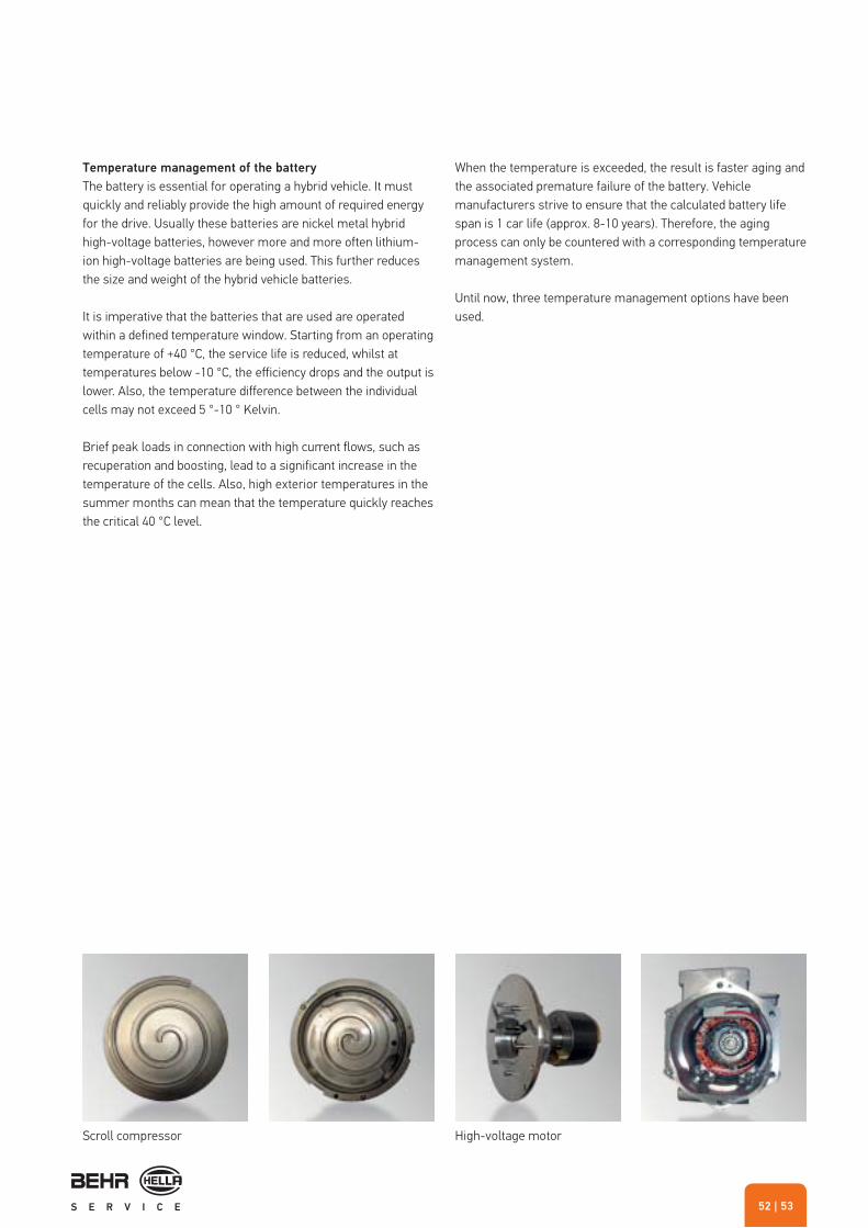
| 5352
Temperature management of the battery
The battery is essential for operating a hybrid vehicle. It must quickly and reliably provide the high amount of required energy for the drive. Usually these batteries are nickel metal hybrid high-voltage batteries, however more and more often lithium-ion high-voltage batteries are being used. This further reduces the size and weight of the hybrid vehicle batteries.
It is imperative that the batteries that are used are operatedwithin a defined temperature window. Starting from an operatingtemperature of +40 °C, the service life is reduced, whilst attemperatures below -10 °C, the efficiency drops and the output islower. Also, the temperature difference between the individualcells may not exceed 5 °-10 ° Kelvin.
Brief peak loads in connection with high current flows, such as recuperation and boosting, lead to a significant increase in the temperature of the cells. Also, high exterior temperatures in the summer months can mean that the temperature quickly reaches the critical 40 °C level.
When the temperature is exceeded, the result is faster aging and the associated premature failure of the battery. Vehicle manufacturers strive to ensure that the calculated battery life span is 1 car life (approx. 8-10 years). Therefore, the aging process can only be countered with a corresponding temperature management system.
Until now, three temperature management options have been used.
Scroll compressor High-voltage motor

INNOVATIVE AIR CONDITIONING MANAGEMENT
Possibility 1
Air is drawn in from the air conditioned vehicle interior and is used to cool the battery. The cool air drawn in from the vehicle interior has a temperature of less than 40 °C. This air is used to flow around the accessible surfaces of the battery pack.
Disadvantages of this are:
� Low cooling effectiveness. � The air drawn in from the vehicle interior cannot be used to
evenly reduce the temperature. � Considerable effort required to guide the air. � Possibly annoying noises inside the vehicle interior caused
by the fan. � There is a direct connection between the passenger
compartment and the battery via the air ducts. For safety reasons (e.g. outgassing of the battery) this is to be classified as problematic.
� Another factor that should not be underestimated is the risk of dirt entering the battery pack, as the air from the vehicle interior also contains dust. The dust is deposited between the cells and, in conjunction with condensed humidity, forms a conductive layer. This layer facilitates the creation of leak currents in the battery.
To avoid this risk, the drawn-in air is filtered. Alternatively, air cooling can also be effected by a separate small air conditioning unit similar to the separate rear air conditioning systems in luxury-class vehicles.
Possibility 2
A special evaporator plate inside the battery cell is connected to the air conditioning system in the vehicle. This is effected in the so-called splitting process on the high pressure and low pressure side via pipes and an expansion valve. This means that the evaporator inside the vehicle and the evaporator plate in the battery, which works like a normal evaporator, are connected to the same circuit.
The various requirements on the refrigerant flow are respectively defined by the different tasks of the two evaporators. Whilst the interior cooling system aims to satisfy the comfort requirements of the passengers, the high-voltage battery must be cooled to varying degrees of intensity depending on the driving situation and the ambient temperature.
These requirements are the defining factors for the complex control of the quantity of evaporated refrigerant. The special design of the evaporator plate and its resulting integration into the battery offer a large contact surface for the heat exchange. As a result it can be ensured that the critical upper maximum temperature of 40 °C is not exceeded.
Compressor
Refrigerant circuit
Cond
ense
r
Evap
orat
or
Pass
enge
r co
mpa
rtmen
t
Batte
ry
evap
orat
or
Battery
NoteEvaporator plates that are directly integrated into the battery cannot be individually replaced. Therefore, the whole battery needs to be exchanged in the event of problems.
Compressor
Refrigerant circuit
Cond
ense
r
Evap
orat
or
Evap
orat
or
plat
e
Evaporator plate
Battery
Possibility 1 Possibility 2

| 5554
When the exterior temperatures are very low, a temperature increase to the ideal temperature of the battery of at least 15 °C would be necessary. However, the evaporator plate cannot contribute to this in this situation. A cold battery is less powerful than one that has the right temperature and it is difficult to charge when the temperatures are clearly below freezing. In the mild hybrid this can be tolerated: in extreme cases, the hybrid function is only available in a limited form. It is however still possible to drive with the internal combustion engine. On the other hand, a battery heater must be installed in pure electrical vehicles so that the vehicle can be started and driven whatever the situation in the winter.
Possibility 3
For large-capacity batteries, the correct temperature control plays a central role. Therefore, at low temperatures it is necessary to provide additional heating for the battery in order to reach the ideal temperature range. It is only in this area that a sufficient range can be achieved in the "Electric Driving" mode.
To enable this additional heating, the battery is integrated into a secondary circuit. This circuit ensures that the ideal operating temperature of 15 °C - 30 °C is maintained at all times.
In the battery block, coolant (water and glycol) flows through an integrated cooling plate (green circuit). At lower temperatures, the coolant can be quickly heated by a heater in order to reach the ideal temperature. If the temperature in the battery rises during the use of the hybrid functions, the heating is switched off. The coolant can be cooled by the air flow through the battery cooler located at the front of the vehicle.
Compressor
Refrigerant circuit
Coolant circuit
Specialheat
exchanger
Cond
ense
r
Batte
ry c
oole
r
Evap
orat
or
Cool
ing
plat
e
Battery
Heating
Possibility 3

INNOVATIVE AIR CONDITIONING MANAGEMENT
If the cooling by the battery cooler is not sufficient at high ambient temperatures, the coolant flows through a special heat exchanger. In it, refrigerant from the vehicle air conditioning system is evaporated. In addition, heat can be transferred in a compact fashion and with high power density from the secondary circuit to the evaporating refrigerant. An additional re-cooling of the coolant is performed. By using the special heat exchanger, the battery can be operated within a temperature range offering optimal efficiency.
Battery cooler
Condenser
Module frame
Power electronics cooler
Coolant radiator
Fan motors
Fan shroud
Cooling components
Special heat exchanger

| 5756
Required further training for repairing hybrid vehicles
Permanent further training is imperative for people who service and repair the complex thermal management systems in hybrid vehicles. For example in Germany, employees that work on these kinds of hybrid systems also need to attend an additional 2-day course to qualify as an "Electrician for high-voltage systems".
Maintenance of hybrid vehicles
The situation is also special when performing routine inspections and repair work (such as e.g. on exhaust systems, tyres, shock absorbers, oil change, tyre change, etc.).
These tasks may only be carried out by employees who have attended the "Electrician for high-voltage systems" course to learn about the risks associated with these high-voltage systems.
Also, it is imperative that tools are used that comply with the specifications provided by the manufacturer of the hybrid vehicle!
This course teaches the employee to recognize the risks when working on systems of this kind and also how to de-energize the system for the duration of the work. It is prohibited for people who have not attended specific training courses to work on high-voltage systems.
During the air conditioning check and service, steps must be taken to ensure that the electric air conditioning compressor is not lubricated with standard PAG oils. These do not have the required insulation properties. Therefore, POE oil is usually used that has these properties.
As a result, air conditioning service units with an internal flushing function and a separate fresh oil reservoir are recommended for the air conditioning check and service in hybrid vehicles. This way mixing of fresh oils of different oil types can be excluded.
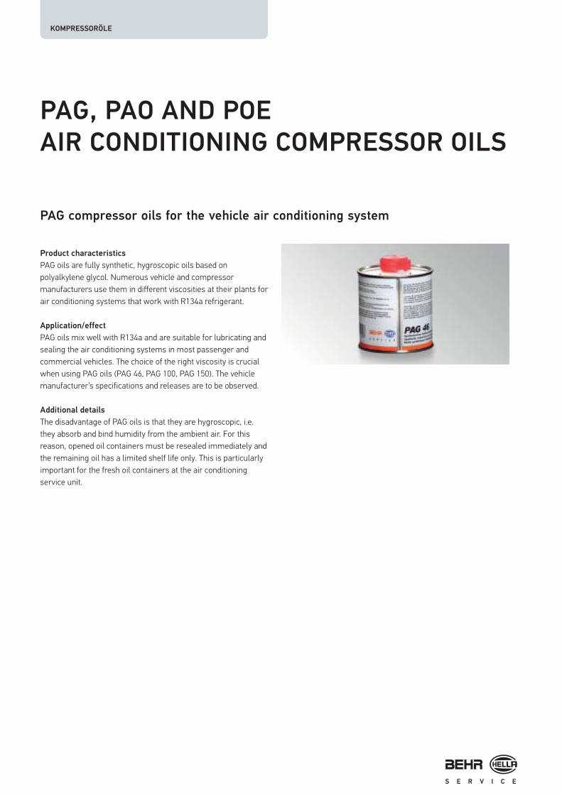
KOMPRESSORÖLE
PAG, PAO AND POE
AIR CONDITIONING COMPRESSOR OILS
Product characteristics
PAG oils are fully synthetic, hygroscopic oils based on polyalkylene glycol. Numerous vehicle and compressor manufacturers use them in different viscosities at their plants for air conditioning systems that work with R134a refrigerant.
Application/effect
PAG oils mix well with R134a and are suitable for lubricating and sealing the air conditioning systems in most passenger and commercial vehicles. The choice of the right viscosity is crucial when using PAG oils (PAG 46, PAG 100, PAG 150). The vehicle manufacturer’s specifications and releases are to be observed.
Additional details
The disadvantage of PAG oils is that they are hygroscopic, i.e. they absorb and bind humidity from the ambient air. For this reason, opened oil containers must be resealed immediately and the remaining oil has a limited shelf life only. This is particularly important for the fresh oil containers at the air conditioning service unit.
PAG compressor oils for the vehicle air conditioning system
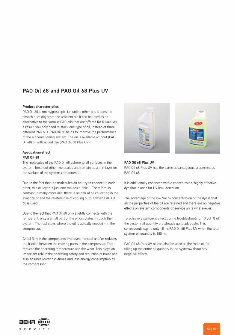
| 5958
Product characteristics
PAO Oil 68 is not hygroscopic, i.e. unlike other oils it does not absorb humidity from the ambient air. It can be used as an alternative to the various PAG oils that are offered for R134a. As a result, you only need to stock one type of oil, instead of three different PAG oils. PAO Oil 68 helps to improve the performance of the air conditioning system. The oil is available without (PAO Oil 68) or with added dye (PAO Oil 68 Plus UV).
Application/effect
PAO Oil 68
The molecules of the PAO Oil 68 adhere to all surfaces in the system, force out other molecules and remain as a thin layer on the surface of the system components.
Due to the fact that the molecules do not try to connect to each other, this oil layer is just one molecule "thick". Therefore, in contrast to many other oils, there is no risk of oil collecting in the evaporator and the related loss of cooling output when PAO Oil 68 is used.
Due to the fact that PAO Oil 68 only slightly connects with the refrigerant, only a small part of the oil circulates through the system. The rest stays where the oil is actually needed – in the compressor.
An oil film in the components improves the seal and/or reduces the friction between the moving parts in the compressor. This reduces the operating temperature and the wear. This plays an important role in the operating safety and reduction of noise and also ensures lower run-times and less energy consumption by the compressor.
PAO Oil 68 Plus UV
PAO Oil 68 Plus UV has the same advantageous properties as PAO Oil 68.
It is additionally enhanced with a concentrated, highly effective dye that is used for UV leak detection.
The advantage of the low Vol % concentration of the dye is that all the properties of the oil are retained and there are no negative effects on system components or service units whatsoever.
To achieve a sufficient effect during troubleshooting, 10 Vol % of the system oil quantity are already quite adequate. This corresponds e.g. to only 18 ml PAO Oil 68 Plus UV when the total system oil quantity is 180 ml.
PAO Oil 68 Plus UV oil can also be used as the main oil forfilling up the entire oil quantity in the systemwithout any negative effects.
PAO Oil 68 and PAO Oil 68 Plus UV

1 2
KOMPRESSORÖLE
Additional details
Can PAO Oil 68 be used for conversions?
Is PAO Oil 68 compatible with other oils?
PAO Oil 68 does not corrode any fluoroelastomer materials such as e.g. tubes or seals, and is ideally suited for converting from R12 to R134a refrigerant.
Since PAO Oil 68 is compatible with many other lubricants and refrigerants, PAO Oil 68 can be used both for refilling and to replace the whole system oil capacity. Due to the independent molecular structure and density, PAO Oil 68 mixes to a certain extent with other oils, but separates from them again when it "comes to rest", and does not enter into a longer-term compound.
This guarantees that the necessary viscosity of the oils is maintained and there is no change in the overall viscosity (see figures 1 and 2). Thanks to its unique combination of highly refined, synthetic oil and special performance-enhancing additives, PAO Oil 68 has a very large operating range (–68 to 315 °C).
How was PAO Oil 68 Plus UV tested?
PAO Oil 68 Plus UV was tested by the manufacturer and independent institutes. Thus, for example, chemical stability was tested in connection with the refrigerant and different O-ring materials on the basis of the so-called "sealed tube test", as per the ASHRAE 97 standard.
All the tests showed a positive result, confirming that negative effects on components in the vehicle air conditioning system or the air conditioning service station can be excluded. Thus PAO Oil 68 Plus UV can be filled directly into a component e. g. the compressor, or via the air conditioning service station into the refrigerant circuit.
PAO-Öl 68

| 6160
Can PAO Oil 68 be used in the case of humidity problems?
PAO Oil 68 is not hygroscopic, i.e. unlike other oils it does not absorb humidity from the ambient air. This means that by simply using PAO Oil 68, humidity problems such as e.g. components icing up or acids being formed, can be counteracted. The application possibilities and the storage ability of PAO Oil 68 are much higher than with conventional oils.
Special features and properties
� No risk of oil collecting in the evaporator and the associated deterioration in cooling performance
� An oil film in the components improves the seal � Reduction of the friction between the components � Reduced energy consumption of the compressor � Unique combination of highly refined, synthetic oil and
special performance-enhancing additives � Very large operating temperature range (–68 to 315 °C) � Low Vol % concentration of the highly active
dye PAO Oil 68 Plus UV, which means protection and reduced wear of the system components and service units

KOMPRESSORÖLE
POE oil for hybrid vehicles
� 120 ml POE oil � 280 mm x 120 mm x 25 mm � Net: 174 g / unit � Gross: 204 g / unit � Packaging unit, small: 1 unit, large: 6 units in one box (305 x 305 x 101 mm)
Part no. 8FX 351 213-111
Product characteristics
Electric air conditioning compressors in hybrid vehicles are powered by an internal electric motor that operates in the high voltage range. The compressor oil in these compressors comes into contact with the electric motor coil, amongst other things. As such, it has to satisfy particular requirements:
� It must not have any adverse effect on the materials used in the compressor.
� It must be resistant to electrical short circuits to a certain degree.
The POE oil offered by Behr Hella Service satisfies theserequirements.
Application/effect
� Can be used in all hybrid vehicles with electric compressor that are filled with POE oil at the factory.
� Bottled in "Spotgun" cartridges, which gives it maximum protection against humidity (problem: POE oil is hygroscopic).
POE oil for electric compressors in hybrid vehicles
Additional details
� Using the Spotgun (cartridge press), it can either be filled straight into the vehicle (with the aid of an adapter tube with low pressure connection) or into the oil tank on the air conditioning service unit
� Spotgun cartridge 120 ml � Each individual cartridge is sealed in an aluminium
sachet � The aluminium sachet also contains a small bag of
desiccant (dryer granulate) to provide maximum protection against humidity
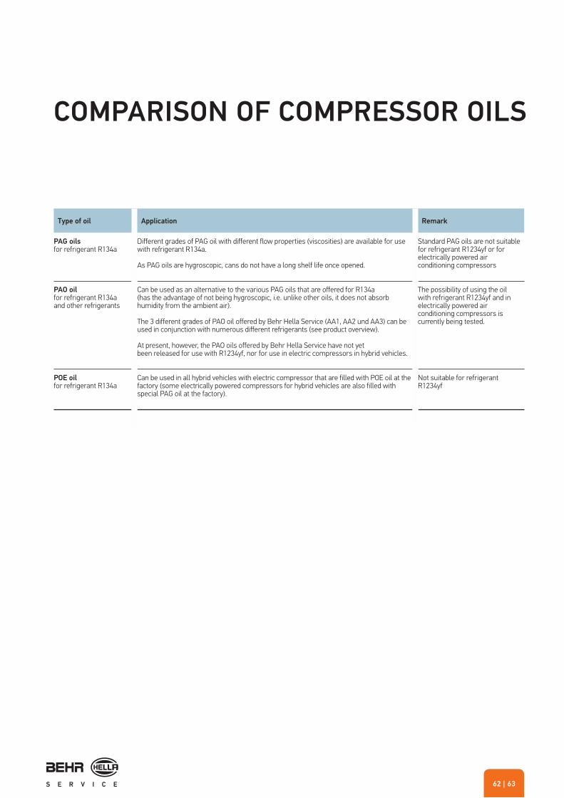
| 6362
Type of oil Application Remark
PAG oilsfor refrigerant R134a
Different grades of PAG oil with different flow properties (viscosities) are available for use with refrigerant R134a.
As PAG oils are hygroscopic, cans do not have a long shelf life once opened.
Standard PAG oils are not suitable for refrigerant R1234yf or for electrically powered air conditioning compressors
PAO oilfor refrigerant R134aand other refrigerants
Can be used as an alternative to the various PAG oils that are offered for R134a (has the advantage of not being hygroscopic, i.e. unlike other oils, it does not absorb humidity from the ambient air).
The 3 different grades of PAO oil offered by Behr Hella Service (AA1, AA2 und AA3) can be used in conjunction with numerous different refrigerants (see product overview).
At present, however, the PAO oils offered by Behr Hella Service have not yet been released for use with R1234yf, nor for use in electric compressors in hybrid vehicles.
The possibility of using the oil with refrigerant R1234yf and in electrically powered air conditioning compressors is currently being tested.
POE oilfor refrigerant R134a
Can be used in all hybrid vehicles with electric compressor that are filled with POE oil at the factory (some electrically powered compressors for hybrid vehicles are also filled with special PAG oil at the factory).
Not suitable for refrigerant R1234yf
COMPARISON OF COMPRESSOR OILS

KOMPRESSORÖLE
Product Application Compressor type RefrigerantViscosity class
Con-tents
Part number
PAG oil Vehicle air conditioning systems*
All types** R134a PAG I (ISO 46) 240 ml 8FX 351 213-031
Vehicle air conditioning systems*
All types** R134a PAG II (ISO 100) 240 ml 8FX 351 213-051
Vehicle air conditioning systems*
All types** R134a PAG III (ISO 150) 240 ml 8FX 351 213-041
Spotgun cartridge Vehicle air conditioning systems*
All types** R134a PAG I (ISO 46) 240 ml 8FX 351 213-061
Vehicle air conditioning systems*
All types** R134a PAG II (ISO 100) 240 ml 8FX 351 213-081
Vehicle air conditioning systems*
All types** R134a PAG III (ISO 150) 240 ml 8FX 351 213-071
PAO oil 68 Vehicle air conditioning systems*
All types**(except impeller type)
R134a,R413a,R22,R12
AA1 (ISO 68)AA1 (ISO 68)AA1 (ISO 68)
500 ml1.0 l5.0 l
8FX 351 214-0318FX 351 214-0218FX 351 214-101
Refrigerator trucks(fresh product vehicles)
Piston compressors** R134a,R507a,R500,R12
Refrigerator trucks(frozen product vehicles)
Piston compressors** R507a,R502,R22
Vehicle air conditioning systems*
All types**(except impeller type)
R404a,R407c,R401b,R401c,R409a,R409b
AA2 (ISO 32) 1.0 l 8FX 351 214-061
Refrigerator trucks(fresh product vehicles)
Piston compressors** R404a,R407c,R409b
PRODUCT OVERVIEW

| 6564
Product Application Compressor type RefrigerantViscosity class
Con-tents
Part number
Refrigerator trucks(frozen product vehicles)
Piston compressors** R404a,R407c,R402a,R403a,R408a
Vehicle air conditioning systems*
Piston compressors** R134a,R413a
AA3 (ISO 100) 1.0 l 8FX 351 214-081
PAO Oil 68 Plus UV Vehicle air conditioning systems*
All types**(except impeller type)
R134a,R413a,R22,R12
AA1 (ISO 68)AA1 (ISO 68)AA1 (ISO 68)
500 ml1.0 l5.0 l
8FX 351 214-2018FX 351 214-2118FX 351 214-221
Refrigerator trucks(fresh product vehicles)
Piston compressors** R134a,R507a,R500,R12
Refrigerator trucks(frozen product vehicles)
Piston compressors** R507a,R502,R22
Vehicle air conditioning systems*
All types**(except impeller type)
R404a,R407c,R401b,R401c,R409a,R409b
AA2 (ISO 32) 1.0 l 8FX 351 214-261
Refrigerator trucks(fresh product vehicles)
Piston compressors** R404a,R407c,R409b
Refrigerator trucks(frozen product vehicles)
Piston compressors** R404a,R407c,R402a,R403a,R408a
Vehicle air conditioning systems*
Impeller-type compressors** R134a,R413a
AA3 (ISO 100) 1.0 l 8FX 351 214-281
POE-Öl Hybrid vehicles Electric compressors** R134a 120 ml 8FX 351 213-111
* Passenger cars, trucks, agricultural and construction machinery** Except electric compressors

NOTES


BEHR HELLA SERVICE GmbH
Dr.-Manfred-Behr-Straße 174523 Schwäbisch Hall, GermanyTel.: 0180-5-25 50 44 (0,14 €/min from the German landline)Fax: 0 79 07-94 46-3 73 79www.behrhellaservice.com
© BEHR HELLA SERVICE GmbHDr.-Manfred-Behr-Straße 174523 Schwäbisch Hall, Germany