service manual - rigmaster...
TRANSCRIPT

© 2012 RigMaster® Power International Ltd. Printed in Canada
Service Manual
MTS T4-6

RigMaster ® MTS T4-6 Service Manual Table of Contents
© 2009 RigMaster® International Ltd. Rev. A Contents
Section 1 Specifications APU Dimensions 1
Fluid Capacities and Requirements 2
Air Conditioning Specifications 4
Engine and Generator Technical Specifications 5
Sensors and Switch Specifications 6
Section 2 Maintenance Introduction to Maintenance 7
Maintenance Schedule 8
Maintenance Checklist 9
Cross Reference Consumable Parts List 10
Replacing the Serpentine Belt 11
Replacing the Fan Belt 13
Replacing the Engine Oil and Oil Filter 14
Replacing the Fuel Filter 15
Replacing the Air Filter 16
Cleaning the 120 Volt AC Generator 17
Cleaning the HVAC Filter 18
Section 3 Serpentine Drive Introduction to the Serpentine Drive System 19
Remove/Replace Auto-Tensioner 20
Remove/Replace Flywheel Pulley 21
Remove/Replace Idler Pulley 22
Serpentine Belt Pulley Alignment 23
Section 4 Frame and Enclosure Enclosure Introduction 25
Disassembly : Right Enclosure (Fan Shroud) 25
Disassembly : Left Enclosure (Radiator/Condenser) 25
Disassembly : Generator Cover 26
Enclosure Parts Diagram 27
Engine Vibration Mounts 28
Engine Mount Plates 30
Cover Latches 30
Preface SM 1
Safety SM 2

RigMaster ® MTS T4-6 Service Manual Table of Contents
© 2009 RigMaster® International Ltd. Rev. A Contents
Section 5 General Engine Introduction to Engine Repairs 31
Glow Plugs 32
Fuel Injectors 33
Fuel Solenoid 34
Injection Pump 35
Fuel Transfer Pump 36
Rear Oil Seal 37
Front Oil Seal 38
Starter Motor 39
Alternator 40
Water Pump 41
Timing Case Cover 42
Engine Thermostat 43
Governor Spring 44
Section 6 Fuel System Fuel System Introduction 47
Priming and Bleeding Procedure: Low Pressure Fuel System 47
Bleeding Procedure: High Pressure Fuel System 48
Typical Fuel System Configuration 49
Fuel System Test Procedures 50
Section 7 Air Filtration System Air Filter Assembly 51
Removing and Replacing the Air Filter Assembly 52
Section 8 Exhaust System Engine Exhaust 53
Removing and Replacing the Exhaust Flex Pipe 53
Removing and Replacing the Muffler 54
(DPF) Diesel Particulate Filter System 55
Section 9 DC Electrical System Control System Information 56
Operation of the Electronic Control System 56
Electronic Control Fault Codes 62
General Electrical Information 65
Power Module Connections 65
System Schematics 71
Testing the Electronic Coolant Control 75
Blower Motor Wiring 76
DPF Back Pressure Wire 76
Alternator Charging 77

RigMaster ® MTS T4-6 Service Manual Table of Contents
© 2009 RigMaster® International Ltd. Rev. A Contents
Sensors, Switches, and Sending Units 78
Battery Fuse 80
Section 10 120 Volt Generator Generator Electrical System Specifications 81
Generator Mounting Diagrams 82
Generator Removal and Installation 82
Testing the Generator 83
Adjusting the Engine Idle 83
Generator Diagnostics Procedures 84
Generator Service Procedures 85
Generator Wiring Electrical Schematics 87 Cables and Outlets 88
Section 11 Engine Cooling and Heating System Engine Cooling System Overview 89
Cooling System Draining, Flushing and Refilling 90
Electric Fan Connections and Relay Locations 91
Troubleshooting a Coolant Leak 92
Heating System 93
Section 12 Air Conditioning System System Overview 94
System Operation and Specifications 95
Electrical Circuit Diagram 96
Performance 97
System Hoses and Components Diagram 98
Hose Replacement 99
Compressor Replacement 102
Diagnostics 103
System Flushing Procedure 108
System Leak Testing 108
Section 13 Troubleshooting Engine System 109
Charging System 110
Fuel System 111
Cooling System 111
HVAC System 112
120V Generator System 112
Serpentine Drive System 113

RigMaster® MTS T4-6 Service Manual Preface
© 2012 RigMaster® International Ltd. Rev. A SM1
SM 1 Scope and Purpose These non-binding service procedures are intended to support authorized RigMaster Power trained dealers and service personnel in the maintenance, installation and servicing of the RigMaster models MTS-T4-6 auxiliary power units. These non-binding service instructions apply to all class 8 O.T.R. vehicles, unless technical modifications on the vehicle influence the serviceability. Depending on the version and vehicle equipment, changes in procedure and diagnosis may
be required that are set outside this manual. In any event the directives in the service manual must be followed and acknowledged engineering conventions must be observed when performing service and maintenance work. It is expected that the technician have a comprehensive set of tools suitable for automotive diagnostic and service work. Definitions
Note
A NOTE describes important information necessary to properly complete a procedure, or information which will make the procedure easier to understand.
Caution
A CAUTION describes a special procedure or special steps which must be taken while completing a task. Disregarding a CAUTION may result in damage to the assembly.
Warning
A WARNING describes a special procedure or steps, which must be taken while completing the procedure where the warning is found. Disregarding a WARNING can result in serious personal injury or death.
Manual Design This manual is divided into sections by engine and assembly systems, with a section dedicated to the preventative maintenance for the APU. For detailed information on installation please refer to the RigMaster Power Installation Manual. For detailed information on engine service please refer to either the Perkins or Caterpillar Service Manual. Please read the entire manual prior to performing RigMaster service and maintenance procedures. If you do not fully understand how to perform a process or procedure or require additional help please contact RigMaster’s Technical Support Department before proceeding.

RigMaster® MTS T4-6 Service Manual Preface
© 2012 RigMaster® International Ltd. Rev. A SM1
Additional Publications
RigMaster® Power; Owner’s Manual, Model MTS T4-6
RigMaster® Power; Installation Manual; Model MTS T4-6
Cummins Generator Technologies, Markon AC Generators; BL 205E Installation, Service & Maintenance Manual; Publication No. M2/0/025ED6E
RigMaster® Power; Authorized Dealer Warranty Handbook
Perkins Service Manual 400C Series will apply; Part Number RENR9825
Perkins; User’s Hand Book, 400 Series, Part Number 100816245
Caterpillar; C0.5 Industrial Engine Service Manual (See Caterpillar Dealer)
Licensed dealerships may review and download additional publications by logging into the RigMaster Power dealer portal.
Visit: www.rigmasterpower.com/login and select “Manuals and Support Material”
Technical Assistance
Before calling for technical assistance please have ready the following:
Current RigMaster Service Manual RigMaster Model and Serial Number In-Service Date Unit Hour Meter Reading Service & Repair History (if available)
Technical Support is available by calling
1(800) 249– 6222
Monday to Friday from 8:00 am to 4:30 pm Eastern Standard Time

RigMaster® MTS T4-6 Service Manual Safety
© 2009 RigMaster® International Ltd. Rev. A SM2
SM 2 Safety
1. Zero Energy State
Caution
To perform service, maintenance and repairs you must disconnect the RigMaster from its battery source. Prior to disconnecting the battery source you must disconnect the J1 connector on the power module to avoid a voltage surge upon reconnect of the battery. In the recommended system configuration the RigMaster shares the battery bank with the vehicles main engine. After disconnecting the battery cables, check the battery posts inside the RigMaster engine cabinet to confirm there is no voltage to the auxiliary power unit (APU).
Warning
Since the unit can start automatically you must disconnect the RigMaster from its battery source. Failure to do this can result in serious injury or death.
2. Safety Cover Switch
Warning
It is critical that this safety cover switch is never deactivated or bypassed when DC power is present; failure to comply may result in serious injury or death..
The safety cover switch (figure S-1) is designed to prevent the RigMaster Power APU from starting when the engine cover is loose or has been removed. When the switch is in the closed position the cover is ON. When the switch is open position the cover has been removed or is loose. The switch is located at the front of the engines enclosure in the lower right hand corner.
3. AutoStart Automatic Start/Stop Feature
Warning
Remember that a properly functioning RigMaster is capable of starting independently of its operator. If the AutoStart feature is enabled, battery voltage, temperature, and time of day can all cause the RigMaster’s engine to start. Please see the cabin controllers operating instructions for further information on the AutoStart feature. You must deactivate this feature prior to refueling.
3. System Safety Buzzer Safety Buzzer In case of accidental starting the RigMaster has a built in audible buzzer as a pre-warning that there is system activity at the control module and the unit will start.
Figure S-1

RigMaster® MTS T4-6 Service Manual Safety
© 2009 RigMaster® International Ltd. Rev. A SM2
Warning
Disconnecting the safety buzzer can result in serious injury or death
4. Engine Hoist Points
Caution
The Perkins and CAT engines have hoist points that are useful for removal and reinstallation of the engine. Under no circumstances should the entire RigMaster APU assembly be lifted by the engine hoist points as they are not intended to hold the increased weight of the engine with fluids, frame and other on-board equipment.
Warning
Hoisting the APU incorrectly can result in serious injury or death
5. Starting Aids
Warning
Do not use any type of starting aids such as ether. Such use could result in an explosion and personal injury, and will render the APU warranty null and void.
6. Starting with the Cover Off
Warning
Some installation or repair/diagnostic procedures require that the APU is started with the engine cover off. Do not deactivate or bypass the safety cover switch. Instead, have another individual assist by manually holding the safety cover switch down in the closed position for the duration of the procedure.
7. Inspection of the Safety Systems The safety systems on the RigMaster APU should be examined and tested prior to performing any service work and at 50 hour intervals to ensure that they are in good condition and proper working order. 8. Safe Working Practices Safe working practices are your responsibility. The use of protective safety equipment is mandatory when performing inspections, service, diagnostics and repairs on the RigMaster APU. Follow your local regulations and guidelines regarding occupational health and safety. 9. Contact Us If you do not fully understand this safety information contact RigMaster’s Technical Support Department toll free at 1(800) 249– 6222 before proceeding with the operation or service of this APU.

RigMaster® MTS T4-6 Service Manual Specifications
© 2012 RigMaster® Power International Ltd. Rev. A 1
Section 1 Specifications
APU Dimensions
APU SPECIFICATIONS
Certified Weight (without the optional DPF) 431 lbs.
Heating Capacity 13,500 BTU
Air Conditioning Capacity 20,000 BTU
DC Charging Capacity 12 Volt, 60 Amp
AC Generator Capacity 120 Volt, 6000 Watts
Figure 1-1
APU Dimensions 1
Fluid Capacities and Requirements 2
Air Conditioning Specifications 4
Other Technical Specifications 5
Sensors and Switch Specifications 6
Engine Enclosure
Width 27” Height 29” Depth 30” Overall 22” off frame rail without S brackets 24” off frame rail with S brackets
HVAC Unit
Width 17.25” Height 10.25” Depth 15.00” Blower Motor 278 CFM
Figure 1-2
Figure 1-2
W
H
D

RigMaster® MTS T4-6 Service Manual Specifications
© 2012 RigMaster® Power International Ltd. Rev. A 2
Fluid Capacities and Requirements
OIL S.A.E./ (S.I.)
Volume 3 Liter / 3 US qt.
Type MTS-T4-6 Models use API CJ4 oil
Viscosity Variable: See Figure 1-3
NOTE
API CJ-4 oil is designed for low sulfur diesel fuel Perkins and CAT engines that are backwards compatible with earlier Tier 2 engines.
CAUTION
Synthetic Oil for diesel engines may be used in the RigMaster.
Service intervals for oil and oil filter replacements remain unchanged at 1000 hours.
Synthetic oil is not suitable for use as break-in oil during the first 1500 engine operating hours.
15W30 and 15W40 are the most commonly used grades of oil.
Oil Viscosity vs. Temperature
Figure 1-3

RigMaster® MTS T4-6 Service Manual Specifications
© 2012 RigMaster® Power International Ltd. Rev. A 3
ENGINE COOLANT TYPE
Engine Coolant
50/50 mixture of ethylene glycol based antifreeze and distilled water. Use only coolants suitable for aluminum core radiators.
System Coolant Capacity 4 litres / 4.23 US quarts.
FUEL SPECIFICATIONS
Fuel Type Ultra Low Sulfur Diesel (ULSD)
Bio Diesel Tier 4 engines – 20% R.M.E.
Use of Biodiesel Fuel This product bulletin has been produced in order to provide you with the latest information regarding the issuing of a Common Statement from Bosch, Stanadyne and Lucas FIE manufacturers. Bio diesel - R.M.E. fuel can be used in Perkins direct injection diesel engines.
However, the following conditions apply:
The fuel must comply with DIN V 51606 (or other approved national standards as they evolve).
RigMaster MTS T4-6 models with Tier 4 engines are rated for mixtures up to 20% RME in mineral oil diesel fuel.
No mixture above the listed percentage for the Tier 4 engine is acceptable, as this can result in filter blocking.
Fuel storage must be to recommended standards, to avoid the absorption of water, and degradation. In any event, storage should not exceed 12 months. Fuel degradation, if allowed to occur, can result in the corrosion of metallic components, and the premature failure of seals.
RME is a powerful solvent. Damage may occur if it comes into contact with paint work.
No legal liability can be accepted for failure attributable to operating products with fuels for which the products were not designed, and no warranties or representations are made as to the possible effects of running these products with such fuels. Non -compliance of the fuel to agreed standards, whether being evident by appearance of the known degradation products of these fuels, or their effects within the fuel injection equipment, will render the manufacturer's guarantee null and void.
If you require further information, please contact your local Perkins or Caterpillar Representative.

RigMaster® MTS T4-6 Service Manual Specifications
© 2012 RigMaster® Power International Ltd. Rev. A 4
Air Conditioning Specifications
AIR CONDITIONING SPECIFICATIONS
Refrigerant Type R134a
Volume of Refrigerant 2.2 lbs; 34oz; 0.95 Kg
Compressor Oil Type SP-15 PAG Oil
Compressor Oil Volume (from factory) 7.0 fl oz; 207 cc; 207 mL
Evaporator Temperature Switch Range = 30º F to 42º F (-1°C
to 7°C)
Binary Pressure Switch Range = 28 to 450 PSI
High Pressure vs. Temperature Readings
High temperatures and pressures are approximate. Readings within 10-15% will deliver acceptable performance. See chart
Suction Pressures – Low Side
Common low side pressure will be between 15-40 PSI depending on the ambient temperature and humidity.
Figure D
Figure 1-4

RigMaster® MTS T4-6 Service Manual Specifications
© 2012 RigMaster® Power International Ltd. Rev. A 5
Engine and Generator Technical Specifications This section lists only basic information about the Perkins and CAT engines. Please see the Caterpillar or Perkins Service Manual for detailed information on engine specifications.
Engine Specifications
Caterpillar equipped RigMaster C0.5 Industrial Engine
Perkins equipped RigMaster 402D-05 Industrial Engine
Engine Tier Tier 4a, 4b
Type 2-Cylinder in-line liquid cooled
Output 13.7 Bhp (10.2 kW) @3600 Rpm
Displacement 0.507 Liter
Valve Lash Inlet/Outlet .2 mm (0.0078 in.)
Aspiration Naturally Aspirated
Cycle 4-stroke
Combustion System Indirect Injection
Engine Rotation Counter Clockwise @ flywheel
Engine Compression 400-450 psi
Compression Ratio 23.5:1
Engine Dry Weight 59 kg (129.8 lbs.)
Engine Components Specifications
Glow Plugs Normal Resistance 1.6 Ω (±0.16Ω)
Glow Plug Current Draw 8-11 amps
Alternator 12 Volt [DC], 60 Amp, Internal Regulator
Starter Motor 12 Volt
Engine Thermostat 82 °C (179.8° F)
Injection Pump Mechanical
Fuel Injectors Open @ 2133 psi
Fuel Lift Pump Mechanical: 4.4 – 10 PSI (30 – 69 kPa)
Water Pump Belt Driven Centrifugal
Generator Specifications
Markon: Model BL 105 6kW; 120 Volts [AC]; 60Hz
Breakers Standard Unit 20 Amp; 60 Hz (2400 watts maximum)
This section lists only basic information about the Markon generator. Please see the Markon: Installation, Service & Maintenance Manual for detailed information on the generator specifications.

RigMaster® MTS T4-6 Service Manual Specifications
© 2012 RigMaster® Power International Ltd. Rev. A 6
Sensor and Switch Specifications
Sensors / Switches Specifications
Oil Pressure Switch (Normally Open)
Switch Open Normal Pressure
Switch Closed Low Pressure (less than 5.7 PSI)
Engine Temperature Switch (Normally Open)
Switch Open – Normal Temperature less than 230°F (110º C)
Switch Closed – Engine Shuts Down at greater than 230°F ± 5ºF (110ºC ± 3ºC)
Flywheel Speed Sending Unit (Speed Sensor)
Normal Resistance 1000 Ω ± 160
Gap at 0.015” from the flywheel
Safety Cover Switch Switch Open – Cover is Off
Switch Closed – Cover is On
Coolant Low Volume Float Switch (Normally Open)
Switch Open – Coolant Full
Switch Closed – Coolant Low
Coolant Controlled Electric Fan Temperature Switch
(Normally Open)
Fan Off - Switch Open below 194 °F (90 C°)
Fan On - Switch Closed above 194 °F (90 C°)
Evaporator Thermostatic Switch
Switch Open Evaporator 31 °F ± 2°F (-0.5°C ± 1°C)
Switch Closed Evaporator 39.5 °F ± 2°F (4.5°C ± 1°C)
Binary Safety Pressure Switch Closed between 28 and 450 PSI

RigMaster® MTS T4-6 Service Manual Maintenance
Section 2 Maintenance
Introduction to Maintenance 7 Maintenance Schedule 8 Maintenance Checklist 9 Cross Reference Consumable Parts List 10 Replacing the Serpentine Belt 11 Replacing the Fan Belt 13 Replacing the Engine Oil and Oil Filter 14 Replacing the Fuel Filter 15 Replacing the Air Filter 16 Cleaning the 120 Volt AC Generator 17 Cleaning the HVAC Filter 18
Introduction to Maintenance The following service procedures describe the replacement of basic service components and general maintenance of the RigMaster APU system. The maintenance schedule must be adhered to in order to maintain the manufacturers’ warranties. Do not use unapproved cross reference parts to perform preventative maintenance. The maintenance checklist S2.3 details service procedures for RigMaster APU’s equipped with the optional diesel particulate filter. This DPF service only applies to T4-6 units that have had these filters installed.
© 2012 RigMaster® Power International Ltd. Rev. A 7

RigMaster® MTS T4-6 Service Manual Maintenance Maintenance Schedule
Note The first oil change must be performed at 50 hours of service and at 1000 hour intervals
there after. Please read the following chart for detailed information. Maintenance schedules listed below are for NORMAL road conditions and the specific hour intervals must be adhered to. For SEVERE conditions perform the scheduled maintenance(s) earlier. Scheduled Intervals Maintenance Items
50 250 500 1000 HOURS X X X X Check Coolant Level X First Engine Oil Change X X X X Check APU for Leaks and Damage
X Inspect Fan Belt Condition and Adjustment
X Inspect Serpentine Belt for Wear X X X Check all Fasteners for Tightness
X Valve Clearance Inspection - intake and exhaust valve clearance are both 0.0078 in / (0.1981mm)
X X Vibration Mounts – pry up on the engine mount plates, there should be less than 1” of upward movement.
X Change Engine Oil and Filter
X Check HVAC Unit Filter - clean if necessary
X Clean Unit Compartment - engine, condenser, and radiator with compressed air or degreaser.
X Check Engine Air Filter - change if necessary
X Check Fuel Filter - change if necessary
X Check Fan Belt - change if necessary 2
X Check Serpentine Belt - change if necessary 2
X Check Coolant - concentration, renew if needed
1 Tier 4 compliant engines uses API oil specification CJ-4, however, CJ-4 oil is backwards compatible and can be used in earlier Tier 2 engines. 2The use of conditioner may extend the service life of belts; consult the belt manufacturer for more information on belt maintenance
© 2012 RigMaster® Power International Ltd. Rev. A 8

RigMaster® MTS T4-6 Service Manual Maintenance
Preventative Maintenance Check List Date: Model No: Serial No:
Hours: Performed By:
Work Order No.
Change Oil and Filters Comments Change oil and filter Change fuel filter Check air filter replace if needed Use compressed air to clean radiator and condenser
Check for loose brackets, door seals and straps Compressor mounting bolts Alternator mounting bolts Check door seal and tie-down straps
Adjust Drive Belts. Clean Generator and Inspect the Engine Mounts for Wear
Fan/Alternator belt Serpentine Belt Clean out the generator using compressed air Check the engine mounts for wear
Check Electrical Connections Positive and negative post studs at the backing plate on the RigMaster for loose connections or corrosion.
APU engine ground check for loose connections or corrosion
Check wiring harness for damage/corrosion i.e. fuses, relays, and other points of connection
Positive and negative cables at the trucks batteries for loose wires or corrosion
Cooling System Run APU with heating set to 85°F: check for leaks Check coolant concentration
HVAC Unit Clean HVAC filter Change the temperature on the controller and make sure the blower motor is blowing heat
Change the temperature on the controller and make sure the blower motor is blowing cold air
Check all cables at the HVAC unit making sure there is no stress on the cables
Reassemble and run the unit Check alternator output (max output 14.8 DCV) Check the bunks extension cord for (120V) power Check the trucks block heater extension cord for (120V) power
Exhaust System – Check for leaks, loose hardware loose brackets or physical damage to the filter itself
Driver Comments
© 2012 RigMaster® Power International Ltd. Rev. A 9

RigMaster® MTS T4-6 Service Manual Maintenance
RIGMASTER POWER APPROVED CROSS REFERENCE PARTS LIST
OIL FILTER AIR FILTER
BRAND
PART No.
BRAND
PART No.
AC Delco PF1233 Perkins 140516250 RigMaster/Mann 00-C1140
Wix 51396 K-Mart Motorvator K014477 AIR FILTER ASSEMBLY Fram PH4386 Baldwin B37 RigMaster 103002
FUEL FILTER FAN BELT
BRAND
PART No.
BRAND
PART No.
Wix 33262 RigMaster RP8-009 NAPA 3262 Bando 2310 9.5 X 790LA Perkins 130366040 Perkins 080109049 Fram C7516 Baldwin PF937 AC Delco GF771
SERPENTINE DRIVE BELT GLOW PLUGS
BRAND PART No. BRAND PART No.
RigMaster RP8-108 Gates K060535 Perkins 185366220
Metric Dimensions 6PK1360 NGK YE01
RECEIVER-DRIER
BRAND PART No.
RigMaster RP9-027B Parker 085268-03
THE USE OF SERVICE COMPONENTS NOT LISTED IN THIS
TABLE MAY CAUSE DAMAGE TO THE ASSEMBLY AND/OR VOID THE
MANUFACTURERS’ WARRANTY
© 2012 RigMaster® Power International Ltd. Rev. A 10

RigMaster® MTS T4-6 Service Manual Maintenance S2.5 Replacing the Serpentine Belt MTS-T4-6 model RigMaster APU incorporates a serpentine belt and auto tensioner system to drive the air conditioning compressor and the 120 Volt AC generator from the flywheel at the back of the engine. The belt moves in a counterclockwise direction.
Back View of Engine
Figure 2-1
# Component Description
1 Belt Auto Tensioner 2 Drive Pulley Adapter 3 Drive pulley 4 Compressor 5 Idle Pulley 6 Generator Pulley
Pulley Alignment When replacing the serpentine belt, 120system you must check the alignment ocan cause wear and premature belt failusee Serpentine Drive Section 3.4 for pro
After changing the belt, but before startdrive system are fastened properly to a
The serpentine belt should be i
© 2012 RigMaster® Power International Ltd.
1
V generatof the pulleyres that arper alignm
Warning ing the engivoid injury.
Note nspected e
5
r or. Pe noent
ne,
ver
2
P
RRRRRR
dullt
pr
ch
y
3
6art#
P8-106 P8-100 P8-101 P9-132 P8-103 P8-102
rive pulley on aeys that are nocovered under ocedures.
eck that all co
1000 hours o
Rev. A
4
serpentine drive t properly aligned warranty. Please
mponents of the
f operation
11

RigMaster® MTS T4-6 Service Manual Maintenance Procedure 1. Remove engine cover. 2. Insert breaker bar or ratchet into serpentine belt auto
tensioner as shown in figure 2-2 (recommended method)
Figure 2-2 Figure 2-3
TOOLS REQUIRED
Adjustable Wrench 3/8 Ratchet
CAUTION You may also use an open ended wrench (figure 2-3), but be sure to protect the radiator in the event that the wrench slips.
3. Lift the breaker bar to release tension on serpentine belt. 4. Remove belt from flywheel pulley while holding tensioner. 5. Release tensioner and remove belt. 6. Replace and route drive belt as shown in figure 2-1. 7. Rotate the engine to ensure that the belt is properly seated on all pulleys before
starting the engine. Serpentine Belt
Figure 2-4 Figure 2-5
© 2012 RigMaster® Power International Ltd. Rev. A 12

RigMaster® MTS T4-6 Service Manual Maintenance S2.6 Replacing the Fan Belt
1) Pivot Bolt
2) Alternator
3) Adjustment Bolt
Figure 2-6
NOTE Inspect the fan belt every 1000 Hours
Procedure 1. Remove the right hand side panel using a 7/16 socket. TOOLS
REQUIRED 12mm Wrench 3/8 Ratchet 12mm Socket 7/16 Socket 16 inch pry bar
2. Loosen the adjustment bolt (3) using a 12mm wrench and a 12mm socket.
3. Loosen the pivot bolt (1) using a 12mm socket. 4. To remove the fan belt, slide the alternator (2) down towards
the engine and remove the belt. 5. Install the new fan belt and slide the alternator (2) up towards
the top of the engine using a 16 inch pry bar until the belt deflection is less than 6 mm. (1/4").
6. When the fan belt is tensioned, tighten the adjustment bolt (3) using a 12mm wrench and 12mm socket. Then tighten the pivot bolt (1) using a 12mm socket.
7. Reinstall the right hand side panel using a 7/16 socket. Make sure the shroud on the side panel does not touch the engine fan blade.
CAUTION Inspect the fan for broken blades or worn tips; if the blade(s) are damaged check the engine mounts and hardware. Also see that a foreign object did not enter the engine compartment.
© 2012 RigMaster® Power International Ltd. Rev. A 13

RigMaster® MTS T4-6 Service Manual Maintenance S2.7 Replacing the Engine Oil and Oil Filter
CAUTION When filling the oil system always fill at the timing cover cap to avoid the possibility of
a hydraulic lock within the cylinder(s) occurring. See note below.
Procedure
1. Remove the oil filler cap from the timing case. 2. Remove the oil dipstick from the dipstick tube
and wipe clean; DO NOT REPLACE THE DIPSTICK AT THIS TIME.
3. Remove the access hatch from the bottom plate of the engine enclosure (6 x 7/16” hex head screws, lock washers and washers).
4. Remove oil drain plug, drain the oil and replace the oil drain plug.
5. Remove and replace the oil filter. 6. Fill the lubricating oil system with the
recommended quantity through fill port on the timing cover. Use only type CJ – 4 engine oil, see section S1.1 for more information on fluid capacities and requirements.
7. Replace the oil filler cap. 8. Operate the engine until operating temperature has been reached. (5 minutes) 9. Stop the engine for 15 minutes to allow oil to drain down to the pan. 10. Check the lubricating oil level on the dipstick and add oil as necessary.
NOTE Replace engine oil and filter every 1000 Hours
Figure 2-8
NOTE Units with the Tier 4 engine have a second fill cap placed on the timing cover. When filling oil on Tier 4 engines, use the timing cover fill port rather than the valve cover cap which will prevent any possibility of hydraulic lock of the cylinders.
Figure 2-7
Oil Dip Stick Marking
Oil Filler Cap on Tier 4a Engine
© 2012 RigMaster® Power International Ltd. Rev. A 14

RigMaster® MTS T4-6 Service Manual Maintenance S2.8 Replacing the Fuel Filter If proper procedures are followed during filter service, a minimal amount of air bleeding is required after changing the filter.
NOTE Inspect the fuel filter every 1000 Hours.
Bleed Screw
Shut Off Valve
Retaining Ring
Fuel Filter
Sediment Bowl
Priming Pump
Priming Lever
Figure 2-9
Filter Replacement Procedure 1. The fuel shut off valve must be closed. (counterclockwise to 3 o’clock position) 2. Remove the retaining ring on the filter sediment bowl and carefully remove the bowl
and filter cartridge. 3. Drain and clean the filter sediment bowl. 4. Install a new filter with the opening of the filter going over the filter housing inlet tube. 5. Reinstall the sediment bowl, and retaining ring. 6. Open the shut off valve and loosen the right bleed screw on the filter head assembly. 7. Bleed the low pressure system. (see below for detailed instructions) 8. Start the engine and check for leak
© 2012 RigMaster® Power International Ltd. Rev. A 15

RigMaster® MTS T4-6 Service Manual Maintenance Bleeding Procedures: Low Pressure Fuel System 1. Position a container or shop wipe under the fuel sediment bowl to contain any spilled
fuel. 2. Using a Phillips screwdriver loosen the right-hand bleed screw located in the filter
head. (Location A Figure 2-10) 3. Prime the fuel system using the manual lift pump lever located on the lift pump.
(Location B Figure 2-11) Since the pump is mechanical and has a diaphragm it may be necessary to manually turn the engine by hand so that the engine camshaft allows full stroke on the lift pump.
4. Continue to pump the lever until the sediment bowl is full and a clear air-free stream of fuel is seen passing the Phillips bleed screw.
5. Tighten the bleed screw in the filter head
NOTE The low pressure system must be completely free of air before the high pressure system can be bled properly. For bleeding the high pressure fuel system please see section S6 of this manual
B A
Figure 2-1 S2.9 Replacin
T
• Care musthe filter is rem• This filter unapproved c
© 2012 RigMaster®
0 Figure 2-11
g the Air Filter:
NOTE he air filter should be inspected every 1000 hours of operation.
CAUTION t be taken to prevent contaminants from entering the intake manifold when
oved. Remove the housing and change the filter off the engine. canister accepts ONLY the Mann 00–C1140 Air Filter. Do not use ross reference parts.
Power International Ltd. Rev. A 16

RigMaster® MTS T4-6 Service Manual Maintenance Front View Top View
A
Figure 2-12 Figure 2-13 Procedure: 1. Remove the air filter canister from the intake manifold. (loosen the
locations A and B as shown in Figure 2-12and 2-13) 2. Protect the air intake manifold from dirt or other debris that may ent3. Remove top cover from the air filter canister. 4. Remove air filter element and clean the inside of air canister. Allow
dry completely. 5. Replace air filter element. (use only manufacturer approved filters)6. Reinstall the air canister lid. (Turn clockwise). 7. Reinstall the air filter canister assembly. 8. Tighten the hose clamps, and double check the lid is on properly.
NOTE Before test running the engine inspect the filter hoses for cracks or
Damaged or degraded hose should be replaced. S2.10 Cleaning the 120 Volt AC Generator:
Note The generator should be cleaned every 1000 hour
1. To clean the generator you must remove the generator cover (7 x 7screws, lock washers and washers), and remove the generators moPlease see section 10 for further information on removal and reinstgenerator.
2. Remove the two Phillips head screws( Location A) and plastic louve(Location B)and clean the core( Location C) using compressed air.(
3. Continue the cleaning until no more debris is seen leaving the geneon the generator should be rotated so that all surfaces in the genercleaned. Ensure that you clean both the inlet and exhaust sides ofcasing.
4. Do not use any liquid cleaners to perform this service.
© 2012 RigMaster® Power International Ltd. Rev. A
B
hose clamps at
er the engine.
the air canister to
brittle sections.
s.
/16” hex head unting hardware.
allation of the
red panel Figure2-13,2-14) rator. The pulley
ators core are the generator
17

RigMaster® MTS T4-6 Service Manual Maintenance
120V Generator
Cover On Exposed Core
B C
A
Figure 2-14 Figure 2-15
Note Cleaning can also be done with the generator mounted in place but you will not be able to remove the cover shown in figure 2-14. S2.11 Cleaning the HVAC Filter:
Note The HVAC filter does not need to be replaced unless it is damaged.
The filter should be cleaned every 1000 hours of operation.
Procedure:
HVAC Unit
1. Unscrew the two thumb nuts (A) and remove the filter housing from the HVAC box.
2. Remove the foam filter from the housing.
3. Wash the air filter using soapy water or blow clean with
Figure 2-16
© 2012 RigMaster®
A
compressed air and allow filter to dry completely.4. Install back on filter housing. 5. Reinsert the air filter housing and
hand tighten the two thumb nuts.
Power International Ltd. Rev. A 18

RigMaster® MTS T4-6 Service Manual Serpentine Drive
© 2012 RigMaster® Power International Ltd. Rev. A 19
Section 3 Serpentine Drive
Introduction to the Serpentine Drive System 19
Remove/Replace Auto-Tensioner 20
Remove/Replace Flywheel Pulley 21
Remove/Replace Idler Pulley 22
Serpentine Belt Pulley Alignment 23
Introduction to the Serpentine Drive System RigMaster MTS T4-6 model systems are equipped with a serpentine drive belt that powers the 120 Volt generator and air conditioning compressor from the flywheel of the engine. This section does not cover the 120 Volt generator pulley, or AC compressor clutch pulley, see sections S10 and S12 in this service manual.
For information on replacement belts see the cross reference list in S2.4.
For information on replacing the serpentine belt see S2.5.
Component Part#
1 Belt Auto Tensioner RP8-106
2 Drive Pulley Adapter RP8-100
3 Drive pulley RP8-101
4 Compressor RP9-132
5 Idle Pulley RP8-103
6 Generator Pulley RP8-102
Figure 3-1
Belt Direction
1
4
6
2
3
5

RigMaster® MTS T4-6 Service Manual Serpentine Drive
© 2012 RigMaster® Power International Ltd. Rev. A 20
Figure 3-3 Figure 3-3
Remove/Replace Auto-Tensioner
WARNING
The auto tensioner unit is not serviceable. Do not attempt to disassemble the auto tensioner as severe injury may result.
The auto-tensioner is mounted to the engine using the auto tensioner mounting bracket.
1. The auto tensioner bracket is to be installed
on the flywheel back plate, with the upper mounting point (1) sharing a mounting bolt with the starter motor.
2. The lower point (2) is bolted to the flywheel
back plate. 3. Hold the auto-tensioner assembly to the
mounting bracket and slide the long bolt through the washer, tensioner and bracket point (3).
4. Secure the tensioner to the bracket with a
washer, and nylon lock nut. 5. Torque the bolt to 33 ft lbs. (47 Nm)
Figure 3-4
Auto Tensioner Mounting Bracket RP8-107
Auto Tensioner RP8-106
1 3
1
2
3

RigMaster® MTS T4-6 Service Manual Serpentine Drive
© 2012 RigMaster® Power International Ltd. Rev. A 21
Remove/Replace Flywheel Pulley Ensure that the flywheel and flywheel pulley adapter are clean and free of any debris prior to installation; this will ensure that the drive pulley is not misaligned.
Figure 3-5
1. Align the drive pulley adapter with the
SAE three point pattern on the flywheel.
2. Install the mounting hardware and
torque to 37 ft lbs. (50 Nm)
Figure 3-6 3. Align the drive pulley with the SAE
three point pattern on the flywheel adapter.
4. Install the mounting hardware and
torque to 37ft lbs. (50 Nm)
Figure 3-7
1
2
3
Drive Pulley Adapter
Fly Wheel Pulley
Drive Pulley
1
3 2

RigMaster® MTS T4-6 Service Manual Serpentine Drive
© 2012 RigMaster® Power International Ltd. Rev. A 22
Remove/Replace Idler Pulley
1. Insert the long bolt through the washer, small
spacer, and idler pulley. (Figure 3-9) 2. Slide the bolt through the pulley spacer and insert
it into the flywheel back plate on the engine. (Figure 3-8)
3. On the rear of the flywheel back plate, install the washer and secure the assembly with the nut. (Figure 3-10)
4. Torque the long bolt to 17 ft. lbs. (23 Nm) (Figure 3-11)
Figure 3-9
Figure 3-10 Figure 3-11
Idler Pulley Mounting Point
Engine Flywheel
Figure 3-8
Figure 3-9
Figure 3-10

RigMaster® MTS T4-6 Service Manual Serpentine Drive
© 2012 RigMaster® Power International Ltd. Rev. A 23
Serpentine Belt Pulley Alignment Pulley Alignment Tool When replacing the serpentine belt, 120V generator or drive pulley on a serpentine drive unit you must align the pulley correctly. Pulleys that are not properly aligned can cause wear and premature belt failures that are not covered under warranty. For this task, there is available a Pulley Alignment Tool which is sold under the part number RP1-001.
Procedure: Alignment of the Generator Drive Pulley using the Alignment Tool
1. Disconnect the battery supply and confirm there is no voltage to the APU. 2. Remove APU front cover. 3. Remove the rear 120 Volt generator cover. 4. Remove the serpentine drive belt. 5. Loosen the set screw on the taper lock bushing on the generator pulley. (See
Figure 3-17) 6. Insert the pulley alignment tool under the auto tensioner. (See Figure 3-13)
7. Attach the pulley alignment tool to the engine flywheel using a metric M10 x 20 bolt. (not supplied with the tool)
8. Align the pulley with the tool such that the point on the tool sits inside the first
groove of the pulley. Rotate the pulley 360° and ensure correct alignment, adjust as necessary. (See Figure 3-14 and 3-15)
Pulley Alignment Tool (RP1-001)
Pulley Alignment
Tool
Mounting Bolt
Figure 3-12
Figure 3-13
Figure 3-11

RigMaster® MTS T4-6 Service Manual Serpentine Drive
© 2012 RigMaster® Power International Ltd. Rev. A 24
9. Fully tighten the serrated set screw over on the taper lock bushing. Torque the set screw to 9 inch pounds. (Figure 3-16)
10. Apply a moderate strength thread locking agent (Blue Loc-Tite™) to the set the screw on the taper lock bushing. (Figure 3-16)
Caution
Do not attempt to start the unit while the tool is attached to the flywheel. Use extreme caution when checking the belt alignment while engine is running.
11. Remove the pulley alignment tool. 12. Clean the serpentine drive belt with a damp rag to remove belt dust. 13. Inspect for damage (replace if necessary), reinstall the serpentine belt to check
for alignment with all pulleys in the serpentine drive system. 14. Reinstall the front cover in order to test-run the engine for 5 minutes and confirm
proper belt alignment. Do a visual check for the alignment. 15. If the belt is misaligned, repeat steps 4 through 13. 16. Reinstall the unit cover.
Figure 3-14 Figure 3-15
Figure 3-16 Figure 3-17
Pulley Assembly (Bottom view)
Pulley Assembly (Side view)
Set Screw Generator Pulley
Taper Lock Bushing
Generator Pulley
Bushing Bolts

RigMaster® MTS T4-6 Service Manual Frame & Enclosure
© 2012 RigMaster® Power International Ltd. Rev. A 25
Section 4 Frame & Enclosure
Enclosure Introduction To perform many of the repair procedures in this manual it may be necessary to remove a portion of the enclosure to gain access to components.
Note
Due to the highly corrosive environment the RigMaster is exposed to, it is recommended that an anti-seize protection be applied to all hardware upon reassembly. It is also recommended that a corrosion inhibitor be used on electrical and mechanical components as a preventative measure.
Disassembly: Right Enclosure (Fan Shroud)
1. Disconnect the safety cover sensor from the wiring
harness and protect it from damage. 2. Remove four plastic cover plugs from the right-hand
enclosure panel. 3. Remove four 7/16” hex head screws, lock washers and
flat washers that secure the right side panel to the frame and remove the panel.
4. Reassembly is the reverse of disassembly. Disassembly: Left Enclosure (Radiator/Condenser) 1. Evacuate the refrigerant and disconnect the two (2) air
conditioning hoses from the condenser. 2. Disconnect the electric condenser fan, and low coolant
sensor from the wiring harness. 3. Disconnect the air filter inlet hose. 4. Drain engine coolant, and remove radiator hoses. 5. Remove the 7/16” hex head screws, lock washers and
flat washers that secure the right louver cover to the left side panel and remove right louver cover.
6. Remove the four (4) 7/16” hex head screws, lock washers and flat washers that secure the left panel assembly to the frame and remove left side panel.
7. Reassembly is the reverse of disassembly.
Enclosure Introduction 25
Disassembly : Right Enclosure (Fan Shroud) 25
Disassembly : Left Enclosure (Radiator/Condenser) 25
Disassembly : Generator Cover 26
Enclosure Parts Diagram 27
Engine Vibration Mounts 28
Engine Mount Plates 30
Cover Latches 30
Figure 4-1
Figure 4-2

RigMaster® MTS T4-6 Service Manual Frame & Enclosure
© 2012 RigMaster® Power International Ltd. Rev. A 26
Warning
Only qualified personnel should service the RigMaster Air Conditioning system.
Disassembly: Generator Cover Procedure 1. Remove seven 7/16” hex head screws, lock washers and flat washers that secure
the rear generator cover to the RigMaster. (Figure 4-3)
2. Remove the generator cover.
Figure 4-3
3. To access the generator wiring remove the 5/16” hex head screw(A), lock washer and
flat washer that secures the lid to the generators junction box(B).
A B
Note
The reset breakers for the generator are located at the front side of the frame.
Figure 4-4 Figure 4-5
Backside of APU

RigMaster® MTS T4-6 Service Manual Frame & Enclosure
© 2012 RigMaster® Power International Ltd. Rev. A 27
Enclosure Parts Diagram
# Description of Frame Component Part Number
1 Cover Buttons RP10-001-12
2 Engine Cover RP10-001-18
3 LH Condenser Cover RP10-001-43
4 LH Side Panel RP10-001-50
5 Frame RP10-001-1A
6 Generator Cover RP10-001-31
7 LH Mounting Bracket RP10-001-57
8 RH Mounting Bracket RP10-001-56
9 Generator Cover Plugs RP12-097
10 RH Side Panel RP10-001-48
11 Oil Quick Access Hatch Cover RP10-001-32
12 Bottom Plate RP10-001-35
13 LH Engine Stiffener RP10-001-4
14 RH Engine Stiffener RP10-001-2
15 Front Engine Mount Plate RP10-001-33
16 Rear Engine Mount Plate RP10-001-34
17 Cover Latches RP12-056
Figure 4-6

RigMaster® MTS T4-6 Service Manual Frame & Enclosure
© 2012 RigMaster® Power International Ltd. Rev. A 28
Engine Vibration Mounts Locations of the vibration mounts and the positioning of mount plates on the frame are illustrated below. (Figure 4-7)
Engine Mount
Five Blue Dot vibration mounts [RP11-002] and Five Shock Pads
[RP11-003] for each location
Note
The mount plates are affixed to the sides of the engine and joined together with stiffeners so that the generator, compressor, and engine are all supported by the engine
mounts.( See figure 4-9)
A: Shock Pad B: Engine Mount Fasteners C: Engine Mount Plate D: 3/8” Flat Washer E: Mount bolt ⅜”-16X2½” F: ⅜”-16 Nut G: ⅜” Lock Washer H: Blue Dot Vibration Mount
Figure 4-7
Compressor Mount Plate position on frame.
Generator Mount Plate position on frame.
Frame
1 2
3 5
4
Figure 4-8

RigMaster® MTS T4-6 Service Manual Frame & Enclosure
© 2012 RigMaster® Power International Ltd. Rev. A 29
Engine Replacement
Notice that the engine is support by the two fixed mount plates and the bottom stiffeners. The generator and compressor are also fixed to the mount plates. This allows all belt driven components and engine to be stabilized as one unit. The vibration mounts support this complete assembly.
Observe engine mounts and plates (Figure 4-9,4-10) as well as the bottom stiffeners (Figure 4-11) when replacing an engine. Damage to these components and improper fastening hardware can cause excessive vibration and premature failure. Replace any worn parts as needed.
Caution
See that the engine is aligned so that the engine cooling fan does not contact the shroud on the right hand panel. Notice the space between the fan and shroud. (Figure 4-12)
Figure 4-11
Figure 4-9 Figure 4-10
Figure 4-12
Gap

RigMaster® MTS T4-6 Service Manual Frame & Enclosure
© 2012 RigMaster® Power International Ltd. Rev. A 30
Engine Mount Plates The serpentine belt system incorporates a fixed component design which reduces the stress on the compressor and generator Rear Engine Mount Plate Front Engine Mount Plate
Figure 4-13 Figure 4-14
Note
Rear engine plate supports the generator and the front engine plate supports the air conditioning compressor. Both components are fixed in position on the mount plates.
Cover Latches The cover latches should be examined frequently to ensure that they are in good condition. You may purchase the rubber tie downs in a kit (RP12-056K) as shown in (Figure 4-15). You may also purchase a single latch and keeper set under the part number RP12-056 (does not include hardware).
Figure 4-15
Rubber Tie-Down
Keeper
Spacer and
Hardware
RP10-001-66 RP10-001-34
Figure 4-9 Figure 4-8-9 Figure 4-8
Figure 4-9

RigMaster® MTS T4-6 Service Manual General Engine
© 2012 RigMaster® Power International Ltd. Rev. A 31
Section 5 General Engine
Introduction to Engine Repairs This section of the service manual outlines some basic engine repairs. The Perkins 400 Series Service and Repair Manual or the Caterpillar C0-5 Service and Repair Manual contain more detailed information on these procedures and should be used as the primary reference when performing engine service and repairs. There may be some RigMaster assembly components that need to be removed in order to service the engine as outlined by Perkins and Caterpillar. This section is intended to provide information about how to perform these engine repairs while installed on the RigMaster APU. Please be aware that the engine bolt sizes are all metric, whereas the other assembly components are likely fastened with SAE sized hardware. Be sure not to use impact guns to replace hardware on the engine. Always use a calibrated torque wrench and refer to the appropriate service and repair manual for torque specifications and proper installation methods.
Note
Dealer Certification and technical training is required by the appropriate engine manufacturer in order to perform warranty engine work. Otherwise warranty may be null and/or void by the manufacturer.
Introduction to Engine Repairs 31
Glow Plugs 32
Fuel Injectors 33
Stop Solenoid 34
Injection Pump 35
Fuel Transfer Pump 36
Rear Oil Seal 37
Front Oil Seal 38
Starter Motor 39
Alternator 40
Water Pump 41
Timing Case Cover 42
Engine Thermostat 43
Governor Spring 44
RigMaster® MTS T4-6 Service Manual General Engine
© 2012 RigMaster® Power International Ltd. Rev. A 32
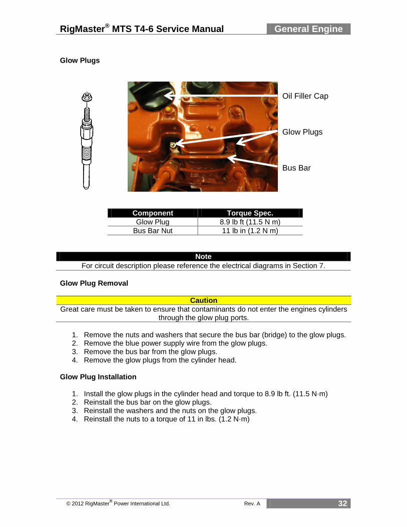
Glow Plugs
Component Torque Spec.
Glow Plug 8.9 lb ft (11.5 N m)
Bus Bar Nut 11 lb in (1.2 N m)
Note
For circuit description please reference the electrical diagrams in Section 7.
Glow Plug Removal
Caution
Great care must be taken to ensure that contaminants do not enter the engines cylinders through the glow plug ports.
1. Remove the nuts and washers that secure the bus bar (bridge) to the glow plugs. 2. Remove the blue power supply wire from the glow plugs. 3. Remove the bus bar from the glow plugs. 4. Remove the glow plugs from the cylinder head.
Glow Plug Installation
1. Install the glow plugs in the cylinder head and torque to 8.9 lb ft. (11.5 N·m) 2. Reinstall the bus bar on the glow plugs. 3. Reinstall the washers and the nuts on the glow plugs. 4. Reinstall the nuts to a torque of 11 in lbs. (1.2 N·m)
Glow Plugs
Bus Bar
Oil Filler Cap
RigMaster® MTS T4-6 Service Manual General Engine
© 2012 RigMaster® Power International Ltd. Rev. A 33
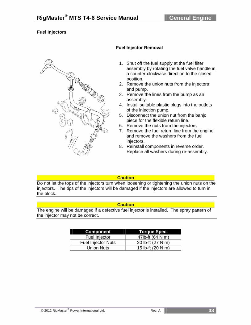
Fuel Injectors
Fuel Injector Removal
1. Shut off the fuel supply at the fuel filter
assembly by rotating the fuel valve handle in a counter-clockwise direction to the closed position.
2. Remove the union nuts from the injectors and pump.
3. Remove the lines from the pump as an assembly.
4. Install suitable plastic plugs into the outlets of the injection pump.
5. Disconnect the union nut from the banjo piece for the flexible return line.
6. Remove the nuts from the injectors 7. Remove the fuel return line from the engine
and remove the washers from the fuel injectors.
8. Reinstall components in reverse order. Replace all washers during re-assembly.
Caution
Do not let the tops of the injectors turn when loosening or tightening the union nuts on the injectors. The tips of the injectors will be damaged if the injectors are allowed to turn in the block.
Caution
The engine will be damaged if a defective fuel injector is installed. The spray pattern of the injector may not be correct.
Component Torque Spec.
Fuel Injector 47lb-ft (64 N m)
Fuel Injector Nuts 20 lb-ft (27 N m)
Union Nuts 15 lb-ft (20 N m)

RigMaster® MTS T4-6 Service Manual General Engine
© 2012 RigMaster® Power International Ltd. Rev. A 34
Fuel Solenoid
Component Torque Spec.
Fuel Solenoid 13 lb ft (17 N m)
Removal of the Fuel Solenoid
1. Remove the solenoid wire by pulling the spade connector from the rear of the solenoid.
2. Unscrew the solenoid counterclockwise from the engine block and remove washer as viewed in the above diagram.
3. Reinstallation is the reverse of removal.
Fuel Solenoid
Solenoid Wire

RigMaster® MTS T4-6 Service Manual General Engine
© 2012 RigMaster® Power International Ltd. Rev. A 35
Injection Pump
Caution
Great care must be taken to ensure that contaminants do not enter the engine through the injection pump cavity. Cover the opening when removing the injection pump.
Component Torque Spec.
Fuel Injection Pump 5 lb ft (6 N m)
Removal of the Fuel Injection Pump
1. Remove Fuel Solenoid. (See section 5.3) 2. Remove high pressure fuel lines. (See section 5.2) 3. Remove the two (2) hex head screws and (2) nuts that secure the pump to the
engine. 4. Remove the oil leak-off pipe. 5. Carefully lift the injector pump assembly until the governor linkage can be
accessed. 6. Remove the cotter pin from the governor linkage, and carefully slide the
connecting link off of the injector slide assembly stud. 7. Remove the fuel injection pump and leave the metal shim in place as it will be
reused. 8. Reassembly is the reverse of disassembly. 9. Torque bolts and screws to 5 lb/ft. (6N-m)
Note
During reinstallation of the pump ensure that the face of the metal shim is clean so a good seal is created when the pump has been reinstalled.

RigMaster® MTS T4-6 Service Manual General Engine
© 2012 RigMaster® Power International Ltd. Rev. A 36
Fuel Pump
Removal of the Fuel Pump 1. Shut off the fuel supply at the fuel filter
assembly by rotating the fuel valve handle in a counter-clockwise direction to the closed position. (3 o’clock position)
2. Remove the fuel supply and discharge lines from the fuel pump.
3. Loosen the two screws that secure the pump to the engine.
4. Gently tap the fuel pump with a rubber mallet to break the seal.
5. Fully remove the mounting screws. 6. Lift the pump away from the engine. 7. Replace the gasket prior to reinstalling the
fuel pump. 8. Reinstallation is the reverse of removal. 9. Torque bolts to 5 lb/ft. (6 N-m)
Component Torque Spec.
Fuel Lift Pump 5 lb ft (6 N m)

RigMaster® MTS T4-6 Service Manual General Engine
© 2012 RigMaster® Power International Ltd. Rev. A 37
Rear Oil Seal Replacement Removal of the Oil Seal 1. Remove serpentine belt from the flywheel pulley. (see S2.5) 2. Remove drive pulley, pulley adapter, flywheel, and auto belt tensioner from the
flywheel back-plate. (see S3 Serpentine Drive) 3. Remove starter motor. 4. Remove flywheel back plate. 5. Remove failed/worn rear crankshaft seal. 6. Clean engine block and flywheel back plate. 7. Install new rear seal. 8. Reassembly is the reverse of disassembly.
Caution
When refitting the flywheel backplate apply an RTV silicone sealant to the block and around the screw holes to improve the seal.
Component Torque Spec.
Flywheel bolts 54 lb-ft (73 N·m)
Back-plate bolts 11 lb-ft (15 N·m)
Pulley Adapter 37 lb-ft (50.5 N·m)
Drive Pulley 37 lb-ft (50.5 N·m)

RigMaster® MTS T4-6 Service Manual General Engine
© 2012 RigMaster® Power International Ltd. Rev. A 38
Front Oil Seal
Removal/Installation of the Front Oil Seal
1. Disconnect safety cover switch. 2. Remove right side panel. 3. Remove fan belt. 4. Remove crankshaft pulley. 5. Extract failed front engine oil seal. 6. Lubricate the engine seal and
crankshaft. 7. Clean and inspect bore housing for
damage. 8. Evenly press a new seal into the
timing case around the crankshaft. 9. Reinstall flywheel pulley and torque
to 69 lb-ft. (93.5 N·m) 10. Reinstall fan belt. 11. Reinstall right side panel.
Component Torque Spec.
Flywheel Pulley 69 lb ft (93.5 N m)

RigMaster® MTS T4-6 Service Manual General Engine
© 2012 RigMaster® Power International Ltd. Rev. A 39
Starter Motor Removal of the Starter Motor 1. Disconnect safety cover switch. 2. Remove right side panel. 3. Remove fan belt. 4. Disconnect the green exciter wire
from the spade terminal of the starter motor.
5. Disconnect the positive battery cable that connects the starter motor to the alternator.
6. Remove the alternator. 7. Remove two (2) hex head bolts,
lock washers and flat washers that fasten the starter motor to the bell housing and remove starter motor.
8. Reinstallation is the reverse of removal.
9. Torque starter mounting bolts to 37 ft lbs. (50 Nm)
10. Torque battery terminal bolt to 11 ft lbs. (15 Nm)
11. Torque starter signal wire to 12 in lbs (1.5 Nm)
Component Torque Spec.
Starter 37 lb ft (50 N m)
Upper Mounting Bolt (Not Shared)
Lower Mounting Bolt (Shared with belt auto tensioner)
Starter Motor

RigMaster® MTS T4-6 Service Manual General Engine
© 2012 RigMaster® Power International Ltd. Rev. A 40
Alternator
Component Torque Spec.
Pivot Bolt 19 lb ft (25 N m)
Adjustment Bolt 19 lb ft (25 N m
Removal of the Alternator 1. Disconnect the safety cover switch and remove the right-hand side panel. 2. Remove four (4) hex head screws, lock washers and flat washers and remove engine
fan. 3. Remove the fan belt. 4. Remove the yellow exciter wire connector and the positive battery cable. 5. Remove the pivot bolt and adjustment bolt. 6. Remove the alternator. 7. Reinstallation is the reverse of disassembly.
Pivot Bolt
Adjustment Bolt
RigMaster® MTS T4-6 Service Manual General Engine
© 2012 RigMaster® Power International Ltd. Rev. A 41
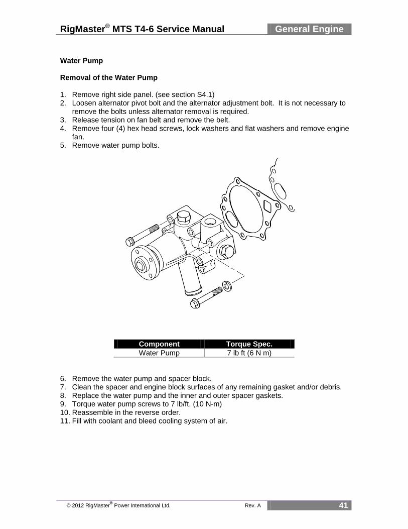
Water Pump Removal of the Water Pump 1. Remove right side panel. (see section S4.1) 2. Loosen alternator pivot bolt and the alternator adjustment bolt. It is not necessary to
remove the bolts unless alternator removal is required. 3. Release tension on fan belt and remove the belt. 4. Remove four (4) hex head screws, lock washers and flat washers and remove engine
fan. 5. Remove water pump bolts.
Component Torque Spec.
Water Pump 7 lb ft (6 N m)
6. Remove the water pump and spacer block. 7. Clean the spacer and engine block surfaces of any remaining gasket and/or debris. 8. Replace the water pump and the inner and outer spacer gaskets. 9. Torque water pump screws to 7 lb/ft. (10 N-m) 10. Reassemble in the reverse order. 11. Fill with coolant and bleed cooling system of air.

RigMaster® MTS T4-6 Service Manual General Engine
© 2012 RigMaster® Power International Ltd. Rev. A 42
Timing Case Cover
Component Torque Spec.
Timing Case 7 lb ft (6 N m)
Remove the Timing Case 1. Disconnect safety cover switch and remove right side panel. 2. Remove fan belt and engine fan. 3. Remove crankshaft pulley. 4. Remove the fuel solenoid and injection pump. 5. Remove the hardware that secures the timing cover case to the engine. 6. With great care, gently tap the timing case with a rubber mallet to break the seal. 7. Remove the timing case cover with the front oil seal. 8. Remove and dispose of joint between cover and block. 9. Inspect the timing cover housing for wear or damage. 10. When replacing the cover use a new gasket and replace the front oil seal. 11. Install the seal guide (Perkins part #21825620) to the crankshaft. 12. Align the locating pin with the locating hole on the oil pump cover and ensure oil pump
cover is concentric with oil pump idler gear. 13. Install new joint to the front of the cylinder block. 14. Move the cover into position while guiding the linkage to the fuel injection pump. 15. Fasten front cover with fasteners and torque to 7 lb/ft. (10 N-m) 16. Remove the seal guide from the crankshaft. 17. Reassemble remaining components in reverse order.

RigMaster® MTS T4-6 Service Manual General Engine
© 2012 RigMaster® Power International Ltd. Rev. A 43
Engine Thermostat
Note
The engine thermostat opens when the engine reaches normal operating temperature 82 Degrees Celsius. (180 Degrees Fahrenheit)
Housing Bolts Drain Plug
Caution
Allow engine to cool for at least one half hour if it has been running prior to this repair. Fluid is hot and under pressure and may cause serious injury.
Removal and Installation of the Thermostat 1. Drain engine coolant by accessing the drain plug on the thermostat housing
and drain coolant into a clean container. 2. Remove the upper radiator hose from the thermostat housing and allow
excess coolant to drain into the container. 3. Remove the two bolts on the top of the thermostat housing and lift the
housing, thermostat, and gasket off the engine. (Always put on a new thermostat gasket when replacing the thermostat.)
4. Install the components in the opposite order and torque to 5 lbs ft (7 Nm). 5. Install the upper radiator hose and fill the radiator with the drained coolant.
Component Torque Spec.
Thermostat Housing 5 lb ft (7 N m)
82 °C Engine Thermostat Thermostat Housing

RigMaster® MTS T4-6 Service Manual General Engine
© 2012 RigMaster® Power International Ltd. Rev. A 44
Governor Spring Removal of the Governor Spring 1. Remove the fuel solenoid. 2. Remove the fuel injection lines from the injection pump and injectors. 3. Remove the oil leak-off pipe that is secured to the fuel injection pump set screw. 4. Remove the set screws and nuts from the fuel injection pump. 5. Carefully lift the injection pump from the cylinder block and pull the clip from the
governor lever stud.(Figure 5-1) Fuel Injection Pump Removal
6. Remove the injection pump 7. Disconnect safety cover switch and remove the right side panel. 8. Loosen the alternator pivot and adjustment bolts and remove the fan belt. 9. Remove the fan bolts, pulley, spacer and fan from the water pump. 10. Remove the nut and washer from the crankshaft pulley. 11. Using a flat ended puller, remove the crankshaft pulley. 12. Clean crankshaft of all debris and lubricate the shaft with engine oil. 13. Remove the hardware that secures the timing case cover to the engine block.
Caution Once you have removed the timing case cover DO NOT CHANGE THE POSITION OF THE CRANKSHAFT or the alignment dowel on the case will not line up with the idler gear when you are reassembling the timing case. (See figures 5-2 and 5-3)
Figure 5-1
Govern Lever
Govern Lever Stud
Cotter Pin
Fuel Rack

RigMaster® MTS T4-6 Service Manual General Engine
© 2012 RigMaster® Power International Ltd. Rev. A 45
Timing Case
Governor Spring
Governor Lever
Stop Lever
Figure 5-4
14. Inspect the timing case for wear and clean the mounting surface. (see figure 5-4) 15. Extract the front seal. 16. Remove old timing case gasket from the block. 17. Remove the failed governor spring. (see figure 5-5) Installation Procedure
1. Install the new front seal into the timing case housing. Ensure that the lip of the seal is spring loaded and facing the inside of the case housing. The seal should be square with the bore of the housing when installed.
2. Install the governor spring between the lever and the timing case housing. (see figure 5-4)
3. Install the new front seal into the timing case housing. Ensure that the lip of the seal is spring loaded and facing the inside of the case housing. The seal should be square with the bore of the housing when installed.
4. Install the governor spring between the lever and the timing case housing. (see figure 5-4)
Alignment Hole
Timing Case Idler Gear
Alignment Dowel
Figure 5-2 Figure 5-3

RigMaster® MTS T4-6 Service Manual General Engine
© 2012 RigMaster® Power International Ltd. Rev. A 46
5. Ensure that the alignment dowel on the timing case and the alignment hole on the idler gear are in-line. (see figures 5-2 and 5 3)
6. Align the timing cover gasket on the block using the alignment dowels on the engine block.
7. Guide the timing case housing on the block studs. Tighten the set screws and nuts to 7 ft/lbs to secure the housing.
8. Install woodruff key and crankshaft pulley. Manually tighten the washer and nut on the crankshaft and torque to 69 lbs-ft (93.5 N·m).
9. Assemble fan components to the water pump and torque fan bolts to 7 lbs-ft. 10. Install fan belt and adjust tension on the alternator. (see S2.6) 11. Install right side panel and reconnect the safety cover switch. 12. Place shim and injection pump into cavity and connect governor spring lever to
the fuel rack using the cotter pin. (see S5.4) 13. Install the high pressure fuel lines to the injection pump and the fuel injectors. 14. Install the fuel run solenoid and connect electrical connector. 15. Install the battery cables to the trucks batteries.
Note You will need to crank the engine several times while bleeding the air from the high pressure lines to the injectors. Once the engine is running check for proper engine idle with and without a load on the engine.
Alignment Dowel
Figure 5-5
Hook to Timing Case
Hook to Governor Linkage

RigMaster® MTS T4-6 Service Manual Fuel System
© 2012 RigMaster® Power International Ltd. Rev. A 47
Section 6 Fuel System
Fuel System Introduction
The RigMaster incorporates a low/high pressure fuel system with fuel supply and return lines interconnected with the vehicle’s fuel system. The engine lift (primer) pump supplies fuel to the filter/sediment bowl assembly and then to the injection pump. When interconnected with the vehicles fuel lines the APU’s fuel supply line requires that a check valve be installed. If using the optional stand pipe a check valve is not necessary as the APU’s fuel system is now independent of the vehicle. For additional information see specifications section 1 of this manual.
Note
This type of fuel system does not de-aerate itself; all air must be bled from the hoses and components. There is an air bleed screw located in the filter head assembly and on the inlet fitting to the injection pump. (See Figure 6-1and 6-2)
Priming and Bleeding Procedure: Low Pressure Fuel System 1. Position a container or shop wipe under the fuel sediment bowl. to. 2. Using a Phillips screwdriver loosen the right-hand bleed screw located in the filter
head. (Location A Figure 6-1) 3. Prime the fuel system using the manual lift pump lever located on the lift pump. (See
note and Location B Figure 6-2) Continue to pump the lever until the sediment bowl is full and a clear air-free stream of fuel is seen passing the bleed screw.
4. Tighten the bleed screw.
Note
The pump is mechanical and has a diaphragm, it may be necessary to manually turn the engine by hand so that the engine camshaft allows full stroke on the lift pump.
Fuel System Introduction 47
Priming and Bleeding Procedure: Low Pressure Fuel System 47
Bleeding Procedure: High Pressure Fuel System 48
Typical Fuel System Configuration 49
Fuel System Test Procedures 50
Figure 6-1 Figure 6-2
A B

RigMaster® MTS T4-6 Service Manual Fuel System
© 2012 RigMaster® Power International Ltd. Rev. A 48
Note
If there is air in the line between the sediment bowl assembly and the injection pump continue bleeding the low pressure system by performing the following additional steps.
Loosen the air bleed nut on the inlet to the injection pump. 1. Operate the manual primer pump lever
until a clear stream of fuel is seen passing the injection pump bleed screw. See that the fuel sediment bowl is free of air.
2. Carefully tighten the injection pump bleed screw
3. Loosen the air bleed screw on the inlet to the injection pump
4. Operate the manual primer pump lever until a clear stream of fuel is seen passing the injection pump bleed nut.
5. Carefully tighten the injection pump bleed screw
Caution
Do not over tighten this bleed nut as it has a hollow core and may break off leaving threads in the injection pump.
Bleeding Procedure: High Pressure Fuel System
Note
The low pressure system must be completely free of air before the high pressure system can be bleed properly
Procedure 1. Loosen both high-pressure line nuts located at
the injectors. 2. Start engine until a clear stream of fuel is
observed from the high-pressure line nuts. 3. If the air bubbles are still present repeat step 2. 4. Tighten the injector line nut, restart engine. 5. Repeat steps 1 to 4 if the engine fails to start Figure 6-4
Injection Pump
Air Bleeder
Figure 6-2
Figure 6-3

RigMaster® MTS T4-6 Service Manual Fuel System
© 2012 RigMaster® Power International Ltd. Rev. A 49
Typical Fuel System Configuration Fuel leaves the vehicles fuel tank via rubber fuel hose to the APU and has a return line back to the vehicle fuel tank. (Figure 6-5)
Fuel can be drawn from one tank without causing any large imbalances in the fuel levels. On some applications the same “T” system can be used for side draw fuel tanks and at dual valves generally located on top of the transmission.
Note
A check valve must be installed when tying into fuel supply lines shared with the vehicle.
Figure 6-6
Figure 6-2
To APU From APU
Fuel Supply from Vehicle Fuel Tank to APU
Fuel Return to Vehicle Fuel Tank from APU
Figure 6-5
Truck Fuel Tank

RigMaster® MTS T4-6 Service Manual Fuel System
© 2012 RigMaster® Power International Ltd. Rev. A 50
Note
The check valve has an arrow indicating the correct direction of fuel flow. Try to keep the arrow on the valve in view; this will help when troubleshooting.
RigMaster Fuel Stand Pipe The fuel stand pipe allows for an independent source of fuel for the APU which does not require a check valve. This is an optional product at this time.
Fuel Tank Stem Fuel Fittings Fuel Output
Figure 6-10
Fuel Fittings at the Crossover Fuel Fittings at the Tank
Figure 6-7 Figure 6-8
Fuel Supply Fittings
Fuel Return Fittings
Figure 6-9
Check Valve
Fuel Fitting Hardware
RigMaster® MTS T4-6 Service Manual Fuel System
© 2012 RigMaster® Power International Ltd. Rev. A 51
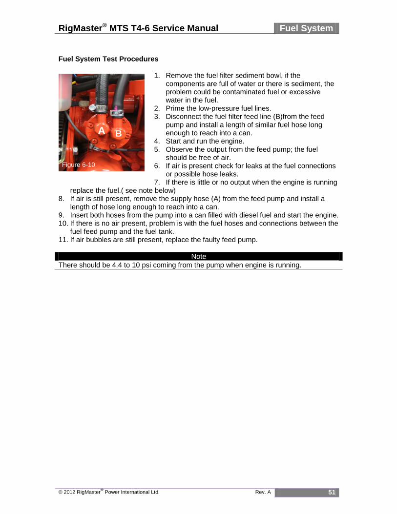
Fuel System Test Procedures
1. Remove the fuel filter sediment bowl, if the
components are full of water or there is sediment, the problem could be contaminated fuel or excessive water in the fuel.
2. Prime the low-pressure fuel lines. 3. Disconnect the fuel filter feed line (B)from the feed
pump and install a length of similar fuel hose long enough to reach into a can.
4. Start and run the engine. 5. Observe the output from the feed pump; the fuel
should be free of air. 6. If air is present check for leaks at the fuel connections
or possible hose leaks. 7. If there is little or no output when the engine is running
replace the fuel.( see note below) 8. If air is still present, remove the supply hose (A) from the feed pump and install a
length of hose long enough to reach into a can. 9. Insert both hoses from the pump into a can filled with diesel fuel and start the engine. 10. If there is no air present, problem is with the fuel hoses and connections between the
fuel feed pump and the fuel tank. 11. If air bubbles are still present, replace the faulty feed pump.
Note
There should be 4.4 to 10 psi coming from the pump when engine is running.
Figure 6-10
A B

RigMaster® MTS T4-6 Service Manual Air Filtration
© 2012 RigMaster® Power International Ltd. Rev. A 50
Section 7 Air Filtration System
Air Filter Assembly The RigMaster APU uses an air canister and high quality pleated filter to prevent debris from entering the engine. The air filter element is not washable and requires that it is examined regularly and replaced as required by the Maintenance Schedule found in section S2.2.
Figure 7-1 Figure 7-2
Caution
Do not use unapproved air filters as they are not designed to fit properly into the air canister. Use of unapproved filters and service components may void engine warranty and cause engine damage.
Air Filter Assembly 51
Removing and Replacing the Air Filter Assembly 52
Mann 00-C1140 Air Canister 103002
Inlet Port
To Intake Manifold

RigMaster® MTS T4-6 Service Manual Air Filtration
© 2012 RigMaster® Power International Ltd. Rev. A 51
Removing and Replacing the Air Filter Assembly
1. Loosen the hose clamp on the air filter inlet
hose at the left hand side panel’s air intake port.(B)
2. Loosen the hose clamp on the air filter outlet hose at the engine air intake manifold.(A)
3. Remove the assembly by lifting it away from the engine and then detaching it from the left hand side panel.
4. Protect the intake port on the manifold such that debris is not able to enter the engine.
Caution
Ensure that you clean the housing away from the engine air intake as contaminants may enter the engine.
5. Take the air canister to a workbench. 6. Open the canister by twisting and removing the top cap counter clockwise. 7. Remove the air filter and clean out the inside of the canister of any dirt and debris.
8. Replace the dirty air filter with a clean air
filter. Use only the approved air filter shown in figure 7-1.
9. Replace the filter assembly by pushing the
air filter inlet hose on the left hand side panel then seating it on top of the intake manifold. Secure the band clamps and see that the hoses are securely connected.
Figure 7-4
A
Figure 7-3
B