variable gain magnetic amplifier and application for...
TRANSCRIPT

http://repository.osakafu-u.ac.jp/dspace/
TitleVariable Gain Magnetic Amplifier and Application for Parameter Invaria
nce Control System
Author(s) Takashima, Yoshinao; Hata, Shiro
Editor(s)
CitationBulletin of University of Osaka Prefecture. Series A, Engineering and nat
ural sciences. 1971, 19(2), p.337-347
Issue Date 1971-03-31
URL http://hdl.handle.net/10466/8159
Rights

337
Variable Gain Magnetic Amplifier and Application
for Parameter Invariance Control System
Yoshinao TAKASHIMA' and Shiro HAtA'
<Received November 13, 1970)
In this paper,. the variable gain magnetic amplifier is described, which has the
characteristics of multiplier and divider as well as fast response and・-moreover has power
output. This magnetic amplifier is theoretically analyzed and then its results are
compared with the experimental ones. Consequently its static characteristic is linear,
though the experimenta! results differ considerably from the theoretical values. It is also
. descrihed that this magnetic amplifier indicates good results when it is applied to the
parameter invariartce control system.
1. Introduction
Up to the present, many investigationsi) of magnetic amplifier have been reported,
but it seems that there are no magnetic amplifiers which serve as multiplier and divider
as well as power amplifier. '
In this paper, the new magnetic amplifier2) which satisfies the above-mentioned
three functions, is proposed. This magnetic amplifier is constructed with three reactors
,and one thyristor, and every core of the reactors is assumed to have the same magnetic
characteristic, Originally the flux is determined by the voltage time integral. Therefore
the core flux can be controlled, by means of the change of either voltage or interval of
integration. In this manner, the first core flux is controlled, then this situation is
transfered to the third core through the second, and finally the powe'r output is
obtained from the output winding on the third core. Since this magnetic amplifier is
based on the principle of ha!fwave magnetic amplifier, good dynamic behavior is
obtained.
Under the assumption of the ideal magnetization curve, the characteristic of this
amplifier is analyzed and consequently it is shown that this amplifier is availabie as
multiplier and divider. These functions are assured experimentally. The available linearity
of the characteristic is recognized, though the experimental values diffbr from the
theoretical ones. - When this magnetic amplifief is used to the parameter invariance control system4) as
,an application, consideral)le performance2) is obtained. ・
* Department of Electronics, College of Engineering.
--
338
win
' Y.TAKAsHIMA and S・HATA
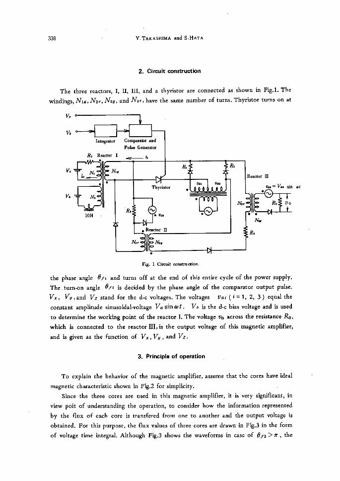
2. Circuit construction
The three reactors, I, II, III, and a thyristor are connected as shown in Fig.1. The
dings, Nig, Mr, Mg, and Nbr, have the same number of turns. Thyristor turns on at
va
va
va
va
Intagrator
Rc Reactor.
.tc'Nc
Comparator and
Pulee Generator
I -i,Mt
e-
M
10H
k
'Rs
Thyristor.
tla1 tla2
'cgo
Rh'
N - tlaB
e Reactor II
Mr
Reactor
li'
'.,M
m
th4 = Vh4
N Ro
sin wt
Ve
the phase angle efi and
The turn-on angle efi
va, va,and iV2 stand
constant amplitude sinusoidal-voltage
to determine the working point
which is connected to
and is given as the function
To explain the behavior
magnetic characteristic shown
Since the three cores
view poit of understand
by the flux of each core
obtained. For this purpose, the flux values of three
of voltage time integral.
Mr il Ms
.
Fig. 1 Circuit construodon.
turns off at the end of this entire cycle of the power supply.
is decided by the phase angle of the comparator output pulse.
fbr the d-c voltages. The voltages vai(i=1, 2, 3) equal the
Vb sin tot. Vb is the d-c bias voltage and is used
of the reactor I. The voltage vo across the resistance Ro,
the reactor llI,is the output voltage of this magnetic amplfier,
of Vi,Vb,and V2.
3. Principte of operation
of the magnetic amplifier, assume that the cores have ideal
in Fig.2 for simplicity. ・ are used in this magnetic amplifier, it is very significant, in
ing the operation, to consider how the information represented
is transfered from one to another and the output voltage is
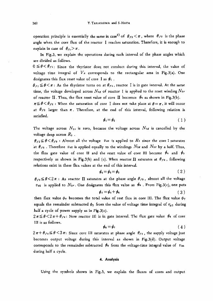
cores are drawn in Fig.3 in the form
Although Fig.3 shows the waveforms in case of ef2>rr,the

レ勧㎡4わZθG4‘ηM卿θ謀。/4η塞pZ静ε747κf/1ρρ露。4¢ゴ。π1bアP4猶4η写θ’ε71ηり4㎡副。θCoπ館oZ 3ン5’∈切τ 339
φ
+φ、
H
一φ。
Fig・21deal mag臓et勉ation curve・
γ比如c
o。、/踊9
a。2価、9
Reactor I
劣:態↑
Reactor II
畿↑
Reactor m
0”
’騨@ ’@ノ@!@ノI/!
エ竺L ηα2踊9 一
残/へ野ズ・ ! 、 / ! 、 , 、 ’ 、 ノ 、ノ
醸濾 海1 i伽・目1癖婦 砺2 1 、
一
ll祠》
Pω’=θ
uξ3「}1
0
ハら9@3、、1\1
;lll
、\八 砺1、、一’
1@;
@3ウl i鰯,、1
i\1 } ; 、
ハら。
1-@ 1ω’=θ@ 「 1
@ 2@ 5、 1
_ 1_;
\ 匝口ト「「晦1 i
、 、
0 1 1、@ l
@ l l@ i.1 ’一嚇 ,’ ノ’//
1\
@倫
Fll
ヨ=k璽ユー8《m漏 ・).
@ 嵯+州ズ 1 / 1/ }!
1_1 1@ 1商 } 3 1 6
l l I『言,=θ= 1 [ I l l l l I《1 衡i l
3111
(a)
(b)
(c)
(d)0 6レ4 π 2π 2π十6レ4 3π_
ω’=θ Fi昏3Vohage w8ve董brms fbr variable gainmagne顧。
ampMie臥(a, b, c)Volt8ge8 acroe8 reactors,
(d) output voLtage・
340 Y.TAKAsHiMA and S・HATA
operation principle is essentially the same in case2) of ef2 < rr , where ef2 is the phase
angle when the core fiux of the reactor I reaches saturation. Therefore, it is enough to
explain in case of ef,>n.
In Fig,3, we explain the operations during each interval of the phase angles which
are divided as fo11ows,
O Se<efi: Since the thyristor does, not conduct during this interval, the value of
voltage time integral of Vx corresponds to the rectangular area in Fig.3(a). One
designates this flux reset value of core I as ¢i .
efi $ e< n; As the thyristor turns on at efi, reactor I is in gate interval. At the same
time, the voltage developed across Nig of reactor I is ap'plied to the reset windingMr
of reactor II.Thus, the flux reset value of core ll becomes ¢3 as shown in Fig,3(b).
rr$e<ef2 : When the saturation of core I does not take place at e=rr, it will occur
at ef2 larger than rr. Therefbre, at the end of this interval, fo11owing relation is
satisfied.
¢i= ¢2 (1)The voltage across ALir is zero, because the voltage across Nig is cancelled by the
voltage drop across R3 .
ef2Se<ef3:Almost all the voltage Va2 is applied to R2 since the coreIsaturates
'at ef2 . Therefore va2 is applied equally to the windings Mg and Mr by a hal£ Thus,
the flux gate value of core II and the reset value of core III become ¢4 and ¢s
respectively as shown in Fig.3(b) and (c). When reactor JI saturates at ef3 , fo11owing
relations exist in these flux values at the end of this interval.
¢4=ips=¢3 (2) ef3Se<2n: As reactor ll saturates at the phase angle ef3, almost all the voltage
va2 is applied to AI3r. One designates this flux value as ¢6 . From Fig.3(c), one puts
¢7=¢s+¢6 (3) then flux value ¢7 becomes the total value of rest fiux in core III. The flux value ¢7
equals the remainder subtracted ¢2 from the value ofvoltage time integral of ila2 during
half a cycle of power supply as in Fig.3(c).
2n$e<2n+ef4: Now reactor III is in gate interval. The flux gate value ¢s of core
III is as follows.
¢s=¢7 (4)2rr+ef4Se<3rr: Since core III saturates at phase angle t7f4 , the supply voltage just
becomes output voltage during this interval as shown in Fig.3(d). Output voltage
corresponds to the remainder subtracted ¢s from the voltage-time integral value of va4
during half a cycle.
4. Analysis
Using the syrribols shown in Fig.3, we explain the fluxes of cores and output

.
V2iriable Gain Mcrgnetic Amplijler and Application for Ilarameter invariance Control System 341
voltage.
Reactor I
Reset flux value ¢i is calculated as follows
' ¢,= th L-liL vbent--:V3xzfLk (s)
Gate fiux value ¢2 is given from App. I・ '
. (NiglM)2Rc Vd ¢2- Ri+(lv,.1lv})2 R. .Ar,. (2+COS efi+ COS ef2)
R, Vi (e.,- ef,) (6) + Ri+(Nig Al})2Rc toNc
In above equation, select the circuit constants as(IVig!AiL)2 Rb>Ri , then one obtains
. Va ¢2;wlv,. (2+ COS 6V'i+ COS ef2) (7)
Substituting eqs.(5) and (6) into eq.(1), following relation is obtained
-VZs}<tEliCli=..zVvd,.(2+COS6L'i+cos6L'2) (s)
Reactor ll ' In like manner, calculate the reset and gate flux values and then, using eq.(2),
fo11owing relation is obtained.
1+ cos ef,= -5-(cos ef,- cos ef,) . (g)
Reactor M
In the same procedures of the above calculations, using eg.(3) and the relation
Val Va4=AlbrlAlbgwhich is derived from that reactor III just constructs the Ramey
circuit, one also obtains the next relation ・ ' cos &2+ cos t7f3=2 cos ef4 (lo)
Output voltage - The mean value Vb of output voltage vo is described as fo11ows..
Va4 Iib= 2. (1+COS ef4) (11)
From eqs.(8), (9), and (10), output voltage Vb of this magnetic amplifier is represented
in the following form.
. Vb= le, Vbe efi (12)where
From AppJI, turn-on angle efi is determined as the function of voltage Vkt and
V2,and is given as follows.
u (13) ef,= to CR lt

342 Y.TAKAsHiMA and S・HATA
Thus, eg.(12) is conseguently written in the form
vb=K IivZVb (14)where Mg K= le, to CR = fCR M (15)
and K is designated as gain coefficient of this magnetic amplifier. In viewing eq.(14),
this magnetic amplifier has clearly the characteristics both as multiplier and divider.
5. Calculated and experimental results
The calculated results from eg.(12) are shown in Fig.4 with parameter 6tfi.In
Fig.4, Nc=175 and IVgg= 2800 are selected.
2s .,319 "" IVb =175 b 20 beE Mg=2800
ls .8 l
lo o,ptN6
K16 5
o O1234 va(V)
Fig. 4 Calculated results from eq. <12).
mo Alo=i7s £8
is sc::Sdnso "",8
lil lo tbu=93V sptN6
2s16
5 rtl6
oo 123 Vi(V)
Fig. 5 Experimental results.
4
.

Vdriable Gain Magnetic Amplifler and Application for Parameter invariance Control System 343
The experimental results are shown in Fig.5. The cores used are Sendelta core of
O.05×80×60×10. In order to decrease the eflfect of the exciting current on the
operation of reactor I, bias voltage Vb is applied to reactor I and, vai, va2,and Va3
somewhat difllbr from each other.
Concerning the relation between efi and ( Vbl Y2) which is represented in eq.(13),
the experimental result agrees exactly with the calculated. Thus this is not shown in the
figure.
' , 6. Consideration for variable gain magnetic amplifier
' ' ' ' The effect of exciting current on magnetic amplifier operation is very important.
Although ideal core characteristic is considered in Section 4, it is reguired to take into
account of voltage drop across the total resistance of the circuit, when the rectangular
cores shown in Fig.6 are used. The effhct of the exciting current on the operation
results in the decrease of the gain coefficient K. The effect '
due to the exciting current is somewhat deduced by using
the low resistances and the superior ,core materials.
Nevertheless,in the circuit which contains winding Nc, the
exciting current is larger than other circuit, because of Hsmall number of turns in Nc winding. The effect due to
the exciting current is, however, avoided by applying the
ampere-turns corresponding to Hc in Fig.6.
The gain coefficient K calculated from Figs. 4 and 5
is tabulated in Table 1. The experimental result is obtained Fig. 6 Rectangular hysteresis loop.
Table 1 Values of Gain CoeMcient K in Eq. (14)
+ds
d
-Hc Hc
-ds
Ca}culatedvalue Experimentalvalue Calculatedvalue
withoutexciting withconstant
current excitingcurrent
K 76.8 51 67.5
from Fig.5 and eq,(15); lei from Fig.5,'R=200 k9, C=O.4ptF, andf=60Hz are
used. Considerable difference in K is recognized between the calculated and the experi-
mental values. The third column of Table 1 indicates the theoretical value3) calculated
from eq.(6) instead of eq.(7), when the exciting current is assumed always to be cons-
tant. This value is close to the calculated value compared with the experimental one.
Since the ex'citing current is not constant in usual cores and even core magnetization
344 Y. TAKAsHiMA and S・HATA
curve indicates minor 1oop, the exciting current changes in more complicated form. For
this reason, the difference between the calculated and the experimentalvalueswill
It should be noted that the values K obtained from the experimental results indicate
almost constant. This means the linear characteristic of experimental results. Since the
calculated relation between the phase.angle t7fi and the voltages VY and V2 is well
agreed with the experimental result and moreover the 1inear relation between the output
voltage Vb and 6V,i or Vle is assured experimentally, it is concluded that this magnetic
. amplifier has the static characteristics both as multiplier and divider,
Next, dynamic characteristic wil1 be considered. Operating essentfally on the
principle of the half wave magnetic amplifier, this responds completely in less than two
cycles of the power supply.
7. Application for parameter invariance control system
' ' Consider that the plant equa'tion is described as fo11owing differential equation of
variable coefficient.
de(t) dt ==-cz2r(t)+lep(t)m(t) (16) ' z(t) stands for the output variable, and m(t) for control force to the plant. Since
lep(t) may be considered to be constant provided that lep(t) changes very slowly
compared with the response of the plant, eq.(16) is represented as fo11ows by means of
psudo Laplace transformation.
Z(s)= ,K;.M'(s) ' (17)
where Kp is the constant value of lep(t) assumed to be fixed. The transfer function of
the model is given as follows.
Y(s) - Kd M(s) -s+a (18)
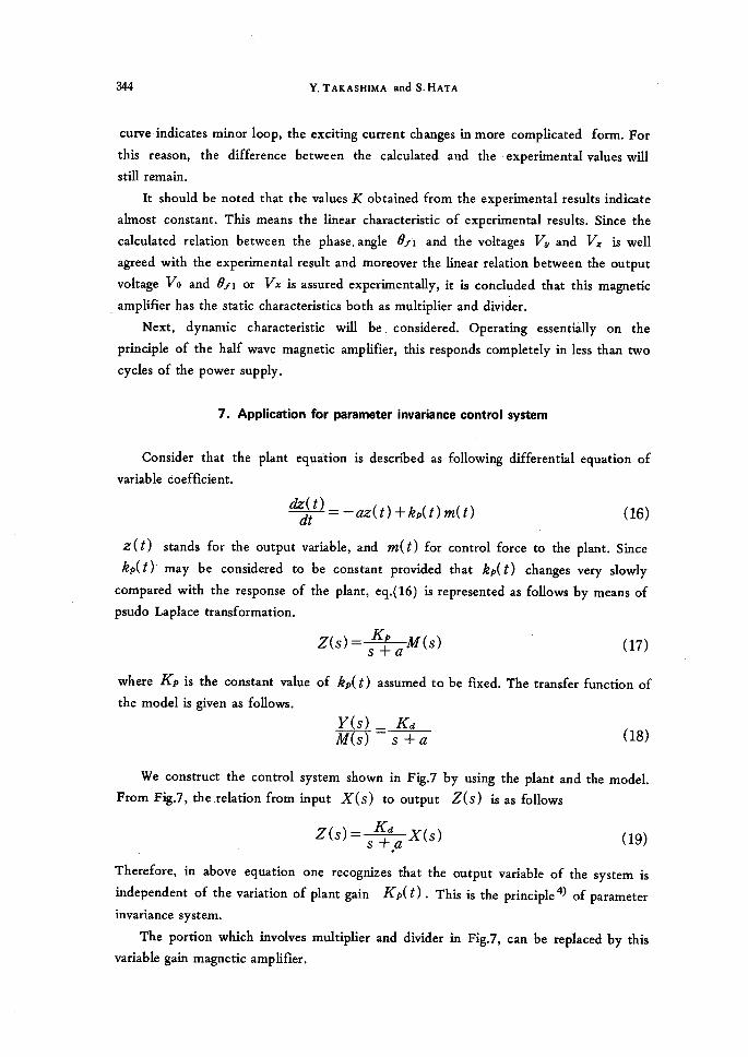
We construct the control system shown in Fig.7 by using the plant and the model.
From Ftg.7, the relation from input X(s) to output Z(s) is as fo11ows
Z(S)= ,K+da X(s) (19) . ' 'Therefore, in above eguation one recognizes that the output variable of the system is
independent of the variation of p!ant gain Kp(t) ・ This is the principle- of parameter
invariance system.
The portion which involves multiplier and divider in Fig.7, can be replaced by this
variable gain magnetic amplifier.

,
lhn:ctble Gain Mdgnetit Amplijler and Application for Ilarameter lvvariance Cbntrol Elystem 345
r- -vl,` X(s) Kn , L- .E(s) t Y(s)t E(s)== Z(s)
i
,
t
= 'I76;M(s
1
,
Ks+aPlant
1
K,
s+a
Z(s)
1yts[' -!- 1 l ・ ・
Model-
-J1
Fig.8 indicates
Fig. 7
the system output
Parumeter invariance
responses
contro1
z(t)
- -llsysteMt
experimented with
'''t: ,--..--t' -+.f.r.T;'-l.rlOVtlsec=i:Ir=:-':';'-'i-r-.im:,tr.tt't-ttt.t t
t4T-z=f-':t,::-"L';-M 4"t.-=-.,-
IHII-
H+,-.4,....'
r rt.t.t t+--ttt=J=t l.t--'fi--+ -
±F't:Ji"f'
・--・- ---・v.=2.siv.3v.,'V.=3V-・2.sv.tr
# +-・ ;-t-・-+" -=・=L'r4--V-e-'
t.
.-tltsi."-・...---I,l.- :-
-{-・..10V1sec -tttt:ttH.;-ttt:.t-t'' f'
=-.t.:t'''-,- ...+".,- -
::-t-
'
'' L--tll-'=' '-'V.=2.5V.3V.V.=3V-.2.5V,tt
'
''
i''';- -:.
--/----.tt.fitt-rrrtt.l-t-..'
..r.1sec.--.'-r--r' -:
tN,--.---J---. =---"---- =-
r. .L:':-t='- za..-L-=J=-., -:/
:=.4=....T-----・-・-'
tt/'L/:-r..v.e.-.. -t,=:..+L..Kp=tl--2-Kp=2'4ISI2sv .--:.t."" sE'-J'"=
t-H-+Lt'"--t-m-tttt T't
r--'. -=
-・ #-・=・-;・ +--;=.-=
-'
2・--4"-Fig. 8 Output responses at) of parameter invariance
control system for the sudden change of Vlt
with (a) K),=2 and (b) K),=4, and (c) for
the sudden change・ of K), with l,1,=3V・
(a)
<b)
(c)
this magnetic

346 Y. TAKAsHIMA and S.HATA
amplifier which is used as multiplier and (livider in Fig.7. In Fig.8 the system parameters
are selected such as Kd=O.16, a=5, and K=51. Ftg.8(a) and (b) show the
experirnental results with Kp =2 and 4 respectively, when Vx changes suddenly from
2.5V to 3V and vice versa. The difference of gain Kp must become the difference in
magriitude of the system response z(t). But one can recognize that the responses are
almost the same to one another except that the amplitude of Kp=4 is slightly less than
that of Kp=2. When Ille remains constant with 3V, Fig.8(c) indicates the response
caused by the sudden change of Kp from 4 to 2 and vice versa. As the time elapses, the
response reaches the previous value which Kp is unchanged, because Kp remains
constant except the instant of change in Kp .This experimental results are almost the
same compared with the results which the analog computer is used instead of this
magnetic amplifier.
8. Conctusions
The characteristics of this magnetic amplifier as multiplier and divider are analyzed
theoretically and then its results are assured by the experiment. Although the
experimental values are considerably deviated from the theoretical values, it is
recognized that the static characteristic is 1inear. The experimental values wi11 reach the
theoretical ones by using superior core materials and reducing the winding resistances.
Since the power output is obtained and the fast response is attained, this magnetic
amplifier is very usefu1 as a control device. This fact is assured fromr the application for
parameter invariance control system.
Furthermore, this characteristics as multiplier and divider are only in the first
guadrant, but the characteristic of the fourquadrant wM be realizable by adopting the
suitable circuit construction.
1)
2)
3)4)
References
For example, D.H.Schaefer and R.L.Van Allen, AIEE Communication and electronics,
56, 160 (1956).
S.Hata, Y.Takashima and F.Miyano, The 12th anriual meeting ofJapan association of
automatic control eng. 208 (1968).
F.Miyano, Graduation thesis, Univ. ofOsaka PreL (1968).
J.M.Ham and M.A.Hasisan, IEEE Trans. automatic control AC-10, 87 (1965).
Following e
Appendix 1
guations exist in the circuit which involves reactor I.

lhriable Gain Mdgnetic Amptifler and Apptication for Parameter Iitvariance Control System 347
ddi, +Ri ii =Vai Nig di
d¢, - Rc ic Iibc+Nc dt -
Nc ic = Nig ii
Solving in above eqs. with respect to ¢2 and integrating from phase angle 61fi
one can obtain the fo11owing relation.
(IVigl Nc )2 Rc Va ¢2= ( 2 + cos ef,+ cos e,,) Ri+(IViglA[c)2Rc toNig
R, Vlo (6tf,- ef,) (6) + Ri+(Nig Nc)2Rc wlVc
to tZie2 ,
Appendix ll
As the integrator is bootstrap circuit in Fig. 1, the
general. w(t) =ckf v2dt
The turn-on angle 6tfi of the thyristor is the pkase
equals the d-c voltage VLt . Thus, eq. (13) is obtained.
n== vz( ef.i )= ,> L`4fL
.・. efi =wcR }lil
output voltage V,V ( t )
angle at
It>dt
which
is given in
the voltage V2;(t)
(13)