using the li-6400 - middlebury collegesites.middlebury.edu/biol323/files/2011/01/6400man.pdf ·...
TRANSCRIPT

Using the LI-6400
PortablePhotosynthesis
System
¨-

NOTICE
The information contained in this document is subject to change without notice.
LI-COR MAKES NO WARRANTY OF ANY KIND WITH REGARD TO THIS MATERIAL, INCLUDING,BUT NOT LIMITED TO THE IMPLIED WARRANTIES OF MERCHANTABILITY AND FITNESS FOR APARTICULAR PURPOSE. LI-COR shall not be liable for errors contained herein or for incidental or consequen-tial damages in connection with the furnishing, performance, or use of this material.
This document contains proprietary information which is protected by copyright. All rights are reserved. No partof this document may be photocopied, reproduced, or translated to another language without prior written consentof LI-COR, Inc.
© Copyright 1998,1999, LI-COR, Inc.Publication Number 9806-122Printing History:
1st Printing July, 1998 - OPEN Software version 3.22nd Printing May, 1999 - OPEN Software version 3.3
Macintosh
¨
is a registered trademark of Apple Computer, Inc.
Printing History
New editions of this manual will incorporate all material since the previous editions. Update packages may be usedbetween editions which contain replacement and additional pages to be merged into the manual by the user.
The manual printing date indicates its current edition. The printing date changes when a new edition is printed.(Minor corrections and updates which are incorporated at reprint do not cause the date to change).
U.S. Patent Numbers: 5,332,901 & 5,340,987. Other patents pending in the U.S. and other countries.
LI-COR, Inc. ¥ 4421 Superior Street ¥ Lincoln, Nebraska 68504Phone: 402-467-3576 ¥ FAX: 402-467-2819Toll-free: 1-800-447-3576 (U.S. & Canada)

Using the LI-6400
iii
Contents
ContentsWelcome to the LI-6400
A Bit of History xiAbout this Manual xiii
Part I: The Basics
1 System Description
What it is, what it does, and how it does it
An Open System 1-2The Flow Schematic 1-4Equation Summary 1-7The System Components 1-12
2 Assembling the LI-6400
Putting it all together
Preparations 2-2Using a Tripod 2-66400-01 CO2 Injector Installation 2-7External Quantum Sensor Installation 2-146400-02B LED Light Source Installation 2-15Powering the LI-6400 2-18Installing System Software 2-19
3 Guided Tours
Learning how to make it work
Before You Start 3-2Tour #1: OPEN Overview 3-4Tour #2: New Measurements Mode Basics 3-14

Contents
iv
Using the LI-6400
Tour #3: Controlling Chamber Conditions 3-20Tour #4: Logging Data 3-41Tour #5: Configuration Adventures 3-51Tour #6: Boot Screen and LPL 3-59
4 Making Measurements
The fundamentals of good measurements
Preparation Check Lists 4-2Some Simple Experiments 4-8Making Survey Measurements 4-21Light Response Curves 4-24CO2 Response Curves 4-30Matching the Analyzers 4-34Stability Considerations 4-41Leaks 4-42Operational Hints 4-47Answers to Questions 4-53
Part II: Useful Details
5 Standard Tools
Menus, Editors, and File Dialogs
Standard Menu 5-2Standard Line Editor 5-5Standard File Dialog 5-9Standard Edit 5-13Hot Keys 5-16Low Battery Warning 5-17The Boot Screen 5-18The LPL Screen 5-20Power ON Hooks 5-23
6 Real Time Data
Viewing real time data using text and graphics
Text Display 6-2Real Time Graphics 6-8

Contents
Using the LI-6400
v
7 Environmental Control
How OPEN controls chamber conditions
OpenÕs Control Manager 7-2Humidity Control 7-7CO2 Control 7-13Temperature Control 7-16Light Control 7-18
8 Light Sensor Considerations
The most important parameter is the hardest to measure
Why Two Sensors? 8-2Specifying the Source and Sensor 8-36400-02 and -02B Light Sources 8-6Gallium Arsenide Phosphide (GaAsP) Sensor 8-7
9 Data Logging
Storing what you want, where you want, when you want
Basic Concepts 9-2Getting Started 9-4Determining What is Logged 9-7Prompts and Remarks 9-12AutoPrograms 9-18AutoProgram Descriptions 9-21Making Your Own AutoPrograms 9-33
Part III: Working With Files
10 The LPL File System
Managing your data storage space
Files, Directories, and Disks 10-2Defragmentation 10-5The Filer 10-6FilerÕs Directory Operations 10-9FilerÕs File Operations 10-11FilerÕs Disk Operations 10-18Troubleshooting 10-21

Contents
vi
Using the LI-6400
11 Downloading Files
Retrieving your data
Connecting the LI-6400 to a Computer 11-3File Exchange Mode 11-4Using WinFX 11-4 Using FX for DOS 11-8Using FX on Macintosh 11-10Using EW 11-12Odds and Ends 11-21Using a Data Capture Program 11-23
12 GraphIt
A tool for viewing and graphing data files
Accessing GraphIt 12-2Data File Format 12-4Defining Plots 12-6Selecting Observations 12-10Curve Fitting 12-14Viewing Data 12-17PlotDef File Format 12-19Storing and Retrieving Graphics Images 12-19
13 Recomputing Data Files
How to recompute data files
Reasons to Recompute 13-2A Step By Step Example 13-2The Details 13-7Hints 13-14
Part IV: Configuration Issues
14 OPENÕs System Variables
Quantities provided by OPEN
Background Information 14-2Measured Variables 14-4Computed Variables 14-9Time and Logging Variables 14-11Status Variables 14-12

Contents
Using the LI-6400
vii
Boundary Layer Variables 14-17List of System Variables 14-19Band Broadening Correction for Water Vapor 14-23
15 Defining User Variables
Equations, Constants, and Remarks
The ComputeList File 15-2ComputeList File Format 15-3Writing and Modifying ComputeList Files 15-7User Defined Constants and Remarks 15-12Examples 15-13Useful Variables and Functions 15-15 The Default ComputeList 15-16Old Style vs. New Style 15-17
16 Configuration Basics
What you need to know to get by
A Definition of Terms 16-2Making Configuration Files 16-4Installation Menu: Behind the Scenes 16-10Modifying Config Files 16-12The Reset Menu 16-16Configuration Command Summary 16-18
17 Using an Energy Balance
Computing what you canÕt measure
The Theory 17-2Using Energy Balance in OPEN 17-6Energy Balance And Boundary Layer 17-9Further Reading 17-11
Part V: Maintenance & Troubleshooting
18 Calibration Issues
How much is good data worth?
CO2 and H2O Analyzers 18-3Flow meter 18-17

Contents
viii
Using the LI-6400
View, Store Zeros & Spans 18-18Zeroing the Leaf Temperature Thermocouple 18-196400-01 CO2 Mixer 18-206400-02(B) LED Source 18-24GaAsP Light Sensors 18-28Calibration and Configuration File Summary 18-30
19 Maintenance & Service
The care and feeding of your new pet
Chemical Tubes 19-26400-03 Batteries 19-8System Console 19-9Real Time Clock 19-12Cables 19-12The Chamber Handle 19-14Leaf Temperature Thermocouple 19-18Leaf Chambers 19-20LED Source Maintenance 19-22Match Valve Maintenance 19-23IRGA Maintenance 19-26Servicing the External CO2 Source Assembly 19-32Shipping The LI-6400 19-35Useful Part Numbers 19-36
20 Troubleshooting
When things go wrong
Power On / Start-up Problems 20-2Real Time Clock Problems 20-6New Measurements Mode Warning Messages 20-7Unreasonable Results 20-9Pump/Flow Problems 20-13IRGA Problems 20-14Match Valve Problems 20-216400-01 CO2 Mixer Problems 20-23Light Source / Sensor Problems 20-30Chamber Problems 20-33Finding Leaks 20-35Soil Chamber Problems 20-39Useful Information 20-42

Contents
Using the LI-6400
ix
21 Diagnostics and Utilities
Useful programs
Diagnostics & Tests Menu 21-2 /Sys/Utility Programs 21-10
Part VI: Programming
22 Programming with LPL
An introduction to the LI-6400Õs programming language
Overview of LPL 22-2Making Objects 22-7Functions 22-12Pointers 22-17Public and Static 22-22Compiler Directives 22-25
23 LPL Topics
Programming with LPL
Stack Control 23-2Conditionals and Loops 23-4Array Operations 23-6Math Functions 23-18Display Control 23-23Keyboard Control 23-29Clock 23-31Event Handling 23-33The Function Keys 23-37I/O Programming 23-39File System 23-46Menus and Editors 23-51Graphics 23-56RS-232 Communications 23-64Analog Measurements 23-66Analog Output Control (D/A) 23-73Digital I/O 23-75Application Tools 23-78Battery and Power 23-82

Contents
x
Using the LI-6400
24 LPL Reference
Keyword Summary
Syntax Summaries 24-2Definitions 24-11The Reference 24-16
25 AutoProgramming Reference
Making them do what you what them to do
Autoprogram Format 25-2Some AutoProgram Listings 25-4Useful AutoProgram Commands 25-12AutoPrograms and the Control Manager 25-19Low Level Control Tools 25-19
26 Customizing Open
ÒCry ÔHavocÕ - and let slip the dogs of warÓ
Using PATCH= 26-2Useful Variables 26-4OpenÕs Hooks 26-7New Style ComputeList Files 26-16Using Spare Channels 26-22
INDEX

Using the LI-6400
xi
Welcome to the LI-6400
A Bit of History
The LI-6400 is LI-CORÕs third generation gas exchange system. In the begin-ning was the LI-6000; it used a third party CO
2
analyzer having the novel (for1983) features of small size, light weight, and low power. Photosynthesis wascomputed by measuring the rate of change of CO
2
with time of a leaf enclosedin a relatively large chamber - a closed system. The LI-6000 was limited bythe signal noise of the analyzer (1-2 µmol mol
-1
) and an unfortunate choiceof method for computing slopes. These problems were corrected in 1986 inthe LI-6200, which sported LI-CORÕs first CO
2
analyzer and much improvedsoftware. It was still a closed system for CO
2
, but had the potential for steady-state transpiration measurements. The steadiness of the state, however, de-pended heavily on a motivated, attentive operator continually adjusting aknob.
While the LI-6200 was fairly well suited for survey measurements, a growingnumber of customers (and potential customers) were looking to answer deep-er questions. The deeper answers could be found in response curves, and thatmeant using a system that could control the environmental quantities impor-tant to photosynthesis: CO
2
, light, humidity, and temperature. Several inno-vators attempted to do various response curves with the LI-6200, withvarying degrees of success. Meanwhile, we were having a very hard time inour attempts to transform that instrument into a next-generation system.
By 1990, having abandoned the idea of enhancing the LI-6200, we restartedwith the question: ÒWhat would the ideal gas exchange system be like?Ó Itwould do response curves, of course, so it would need the ability to controlchamber conditions. To us,
ideal
response curves meant
labor-free
responsecurves, so manual controls were out, computer controls were in. Responsecurves should be seen, not imagined, so we needed built-in graphical capabil-ity. The ideal system would also do survey measurements: you should be ableto carry it around, clamp onto a leaf using only one hand (our previous sys-tems needed two or three), and be done with the measurement quickly. Ques-

Welcome to the LI-6400
A Bit of History
xii
Using the LI-6400
tions of weight, power, and compactness thus emerged. Could the capabilitiesof a laboratory system (response curves) be squeezed into a field system (sur-vey measurements)?
Challenges loomed, two of them formidable: CO
2
and H
2
O control is donebest by having gas analyzers right in the leaf chamber, but suitable IRGAs didnot exist. Secondly, chamber CO
2
could in principle be controlled by mixingscrubbed air and pure CO
2
(available in very portable 12 gram cylinders), butagain, a suitable mixing device did not exist. So, we set about inventing them.
Five years and one name change
1
later, we shipped the first LI-6400. Andmany more since then. We trust that this instrument will serve you well, andstand ready with support and help as you put it to work. Welcome to theLI-6400.
1.
It started out as the LI-6300.

Welcome to the LI-6400
About this Manual
Using the LI-6400
xiii
About this Manual
When confronted with a new instruction manual, most people turn to the sec-tion named ÒAbout this manualÓ for one simple reason: to find out how muchthey can skip. Since this manual has 26 chapters, you are probably eager toskip most of them.
YouÕre in luck. You can.
Where to Start?
Select the category that best describes you, and follow the suggested itiner-ary.
¥
New to the LI-6400; new to gas exchange; and fairly impatient
Chapter 2: Assembling the system.Chapter 3 (The minimum for learning the software is):Tour #1, stop after Step 5.Tour #2, the whole thing.Tour #3, Experiments 1, 2, and 5.Chapter 4: Do the check lists, and the simple experiments.Having measured some leaves (and satisfied your impatience), you mightwant to go back and pick up the parts you skipped in Chapters 3 and 4.
¥
New to the LI-6400; new to gas exchange; methodical and thorough
Work through Chapters 1, 2, 3, and 4. YouÕll understand the LI-6400 and thefundamentals of making measurements fairly well by the end.
¥
New to the LI-6400, experienced at gas exchange measurements
Skim Chapter 1.Chapter 2: Assembling the system.Chapter 3: Tours 1 through 5.Chapter 4: The check lists are important; pick and choose after that.
¥
Experienced with the LI-6400
Consider working through Tour #3 in Chapter 3; youÕll improve your under-standing and Òfeel forÓ how the LI-6400 does chamber control. Note thecheck lists at the start of Chapter 4, and the de-emphasis on zeroing and spansetting. Finally, a Troubleshooting Guide (Chapter 20) is now available.
The Old Manuals
If you are not a new LI-6400 user, you may be wondering how
Using theLI-6400
relates to the original documentation,
The LI-6400 Primer
and
TheLI-6400 Technical Reference
. If you have these original manuals, you cansafely get rid of them, because
Using the LI-6400 includes the relevant priormaterial, and adds much new material.

Welcome to the LI-6400About this Manual
xiv Using the LI-6400
Electronic version This manual is also available as an Adobe¨ Acrobat¨ file, on CD and fromour web site (www.licor.com). All cross references in the text, table of con-tents, and index are hyper-linked, allowing one-click access. (Version 3.0 ofAdobe¨ Acrobat¨ Reader is required. You can download this software forno charge from www.adobe.com)

Part I
The Basics


Using the LI-6400 1-1
1System Description
What it is, what it does, and how it does it
AN OPEN SYSTEM 1-2Measuring Differentials 1-2The Air Supply 1-3Leaks 1-3
THE FLOW SCHEMATIC 1-4Matching the IRGAs 1-6
EQUATION SUMMARY 1-7Transpiration 1-7Total Conductance to Water Vapor 1-8Stomatal Conductance to Water Vapor 1-9Net Photosynthesis 1-9Intercellular CO2 1-10Everything Else 1-11Summary of Symbols 1-11
THE SYSTEM COMPONENTS 1-12The Standard Parts 1-13The Optional Accessories 1-14

System Description
1-2 Using the LI-6400
1This chapter acquaints you with the LI-6400Õs operating principle, majorcomponents, and equations.
An Open System
Measuring DifferentialsThe LI-6400 is an open system, which means that measurements of photosyn-thesis and transpiration are based on the differences in CO2 and H2O in an airstream that is flowing through the leaf cuvette (Figure 1-1).
Sample IRGA
Reference IRGA
Flow x DCO2
AreaPhoto = Trans =
Flow x DH2O
Area
Figure 1-1. In an open system, photosynthesis and transpiration are computedfrom the differences in CO2 and H2O between in-chamber conditions and pre-chamber conditions. The equations are given in Equation Summary on page 1-7.
Sample IRGA
Reference IRGA
FlowMeter
FlowMeter
Traditional Open System
LI-6400
Console
Console
Cuvette
Cuvette

System DescriptionAn Open System
Using the LI-6400 1-3
The LI-6400 improves upon traditional open systems by having the gas ana-lyzers in the sensor head. This eliminates plumbing-related time delays, andallows tight control for responding to leaf changes. For example, if stomataclose, the control system immediately detects the drop in water vapor and cancompensate. Similarly, a sudden change in light level will cause an immedi-ate change in photosynthetic rate, which will be detected as a change in theCO2 concentration. The speed of detection is not a function of the systemÕsflow rate, as in traditional systems, since the sample IRGA is in the cuvette.
There is a second advantage of having the IRGAs in the sensor head. The tra-ditional system has the potential for concentration changes (because of watersorption and CO2 diffusion) as the air moves from the reference IRGA to thechamber, and again from the chamber back to the sample IRGA. This is nota problem for the LI-6400, because the IRGA measurements are made afterthe air has travelled through the tubing.
The Air SupplyOne strength of an open system is that the incoming air stream can be condi-tioned. That is, its humidity, CO2 concentration, temperature, etc. can be es-tablished by some means prior to entering the system.
Regardless of what is done to the incoming air, however, one thing is crucial:
This is especially true for CO2, where the potential for fluctuations is huge(your breath, for example, is probably about 50,000 µmol mol-1). Fluctua-tions in concentration will cause concentrations differences to be very erratic.
LeaksÒPressure inside the leaf chamber is slightly above ambient to ensure thatleaks are outward, so outside air does not enter the chamber and affect theCO2 and H2O concentrations.Ó This argument for the advantage of an opensystem has been made for a long time, and itÕs true - as far as it goes. Thereis another process at work, however: diffusion. CO2 will always diffuse fromhigher concentrations toward lower, even against a pressure gradient, and isonly limited by the material through which it is moving. The black neoprenegaskets that we use on the LI-6400 (except for the light source) have the low-est diffusivity to CO2 of all the gasket material we have tested, but itÕs notperfect. Diffusion effects are measurable at low flow rates when there is a
Incoming concentrations must be stable.

System DescriptionThe Flow Schematic
1-4 Using the LI-6400
1
large concentration difference between chamber and ambient. See DiffusionLeaks on page 4-43 for more details.
The Flow SchematicThe LI-6400 provides mechanisms for modifying the incoming airÕs CO2 andH2O concentrations (Figure 1-2 on page 1-5). There are chemical tubes forscrubbing CO2 and H2O, and air can be diverted through these tubes in anyproportion desired. CO2, however, is best controlled by scrubbing all of itfrom the incoming air, and using the 6400-01 CO2 mixer to inject just enoughCO2 to provide a stable concentration at the desired value. If the 6400-01 isnot part of your system, you will need to use a buffer volume. For a morecomplete discussion of buffer volumes, see Air Supply Considerations onpage 4-47.
Humidity control in the leaf cuvette is achieved by regulating the flow ratethat is going though the cuvette. In units without a CO2 mixer, the pumpspeed controls the flow, and in units with a CO2 mixer, a flow diverter regu-lates this flow.

System DescriptionThe Flow Schematic
Using the LI-6400 1-5
75%Flow
Flow Meter
Bypass Valve
Bypass Valve
Restrictors
Desiccant
CO2 Scrubber
SampleReference
Air In
Pump
25%
75%25%
CO2FlowControl
AirFlowControl
Pump
CO2
Flow
Flow Meter
Vent
Bypass Valve
Bypass Valve
Liquid CO2
Vent
Restrictors
Desiccant
CO2 Scrubber
Pur
e C
O2
SampleReference
Air In
Figure 1-2. LI-6400 flow schematic, with and without a 6400-01 CO2 mixer.
Schematic with a 6400-01 CO2 Mixer
Schematic without a 6400-01 CO2 Mixer

System DescriptionThe Flow Schematic
1-6 Using the LI-6400
1
Matching the IRGAsThe heart of the computation of transpiration and assimilation is the measure-ment of the concentration differences. Since these differences are measuredby two independent gas analyzers, provisions must be made to check the IR-GAs against one another. One way to do this is to compare the IRGAs whenthe leaf chamber is empty, and adjust one so that they match. Matching in thismanner is a problem, however, because you donÕt want to remove the leaffrom the chamber in the middle of an experiment. The LI-6400 provides amechanism to match the IRGAs without disturbing the leaf: it is called matchmode, and it is illustrated in Figure 1-3.
Match mode is something that you do at least once at the start of the day, andperiodically throughout the day. Matching is important when the DCO2 orDH2O value is small (low rates, small leaf areas). For example, a
1 µmol mol-1 offset between the two CO2 IRGAs is trivial when the DCO2 is
75 µmol mol-1, but represents a significant error if the DCO2 is only
3 µmol mol-1.
Figure 1-3. In Match Mode, leaf chamber air is measured by both sample and ref-erence IRGAs, allowing the sample IRGA to be adjusted to match the reference IR-GA.
SampleReference
Normal
SampleReference
Match

System DescriptionEquation Summary
Using the LI-6400 1-7
Equation SummaryIf you are not interested in the details of the LI-6400Õs gas exchange calcula-tions, you can safely skip this section.
The equations for net photosynthesis, transpiration, etc. are essentially thosederived by von Caemmerer and Farquhar1. Note also that these equations rep-resent the instrumentÕs defaults, and can be modified or replaced as desiredby the user (Chapter 15).
TranspirationThe mass balance of water vapor in an open system (Figure 1-4) is given by
(1-1)
where s is leaf area (m-2), E is transpiration rate (mol m-2 s-1), ui and uo are
incoming and outgoing flow rates (mol s-1) from the chamber, and wi and wo
are incoming and outgoing water mole fractions (mol H2O mol air-1). Since
(1-2)
we can write
(1-3)
1.S.von Caemmerer and G.D.Farquhar (1981) Some relationships between thebiochemistry of photosynthesis and the gas exchange of leaves, Planta 153:376-387
ui uo
E
Figure 1-4. Measuring fluxes in an open system. Transpiration rate E and photo-synthetic rate a change the water and CO2 concentrations of air as it passesthrough the chamber. Transpiration also causes the exit flow uo to be greater thanthe incoming flow rate ui.
wi wo
a
ci co
sE uowo uiwiÐ=
uo ui sE+=
sE ui sE+( )wo uiwiÐ=

System DescriptionEquation Summary
1-8 Using the LI-6400
1
which rearranges to
(1-4)
The relationships between the terms in (1-4) and what the LI-6400 measuresare
(1-5)
where F is flow rate (µmol s-1), Ws and Wr are sample and reference water
mole fractions (mmol H2O mol air-1), and S is leaf area (cm-2). The equationthat the LI-6400 uses for transpiration is thus
(1-6)
Total Conductance to Water VaporThe total (includes stomatal and boundary layer) conductance of the leaf gtw
(mol H2O m-2 s-1) is given by
(1-7)
where Wl is the molar concentration of water vapor within the leaf
(mmol H2O mol air-1), which is computed from the leaf temperature Tl (C)and the total atmospheric pressure P (kPa)
(1-8)
Eui wo wiÐ( )
s 1 woÐ( )---------------------------=
ui F 106
¤=
wi Wr 103
¤=
wo Ws 103
¤=
s S 104
¤=
EF Ws WrÐ( )
100S 1000 WsÐ( )-------------------------------------------=
gtw
E 1000Wl Ws+
2--------------------Ðè ø
æ ö
Wl WsÐ------------------------------------------------=
Wl
e T l( )
P------------ 1000´=

System DescriptionEquation Summary
Using the LI-6400 1-9
The function e(T) is saturation vapor pressure (kPa) at temperature T (C). Theformula used by the LI-6400 is (14-21) on page 14-10.
Stomatal Conductance to Water VaporThe stomatal conductance gsw to water vapor (mol H2O m-2 s-1) is obtainedfrom the total conductance by removing the contribution from the boundarylayer.
(1-9)
where kf is a factor based on the estimate K of the fraction of stomatal con-ductances of one side of the leaf to the other (termed stomatal ratio through-out this manual),
(1-10)
and gbw is the boundary layer conductance to water vapor (mol H2O m-2s-1)from one side of the leaf. The boundary layer conductance correction thus de-pends on whether the leaf has stomata on one or both sides of the leaf.
Net PhotosynthesisThe mass balance of CO2 in an open system is given by
(1-11)
where a is assimilation rate (mol CO2 m-2 s-1), ci and co are incoming and
outgoing mole fractions (mol CO2 mol air-1) of carbon dioxide. Using (1-2),we can write
(1-12)
which rearranges to
gsw1
1gtw--------
k f
gbw---------Ð
-----------------------=
k fK
21+
K 1+( )2
---------------------=
sa uici uocoÐ=
sa uici ui sE+( )coÐ=

System DescriptionEquation Summary
1-10 Using the LI-6400
1
(1-13)
To write (1-13) in terms of what the LI-6400 measures, we use (1-5) and
(1-14)
where Cr and Cs are sample and reference CO2 concentrations
(µmol CO2 mol air-1), and A is net assimilation rate of CO2 by the leaf
(µmol CO2 m-2 s-1). Substitution yields
(1-15)
Why does transpiration appear in the equation for photosynthesis? (Askingthis question means you didnÕt follow the derivationÉ) The short answer isthat it serves as a dilution correction; as the leaf adds water vapor to the cham-ber, it dilutes all other gasses, including CO2.
Intercellular CO2The intercellular CO2 concentration Ci (µmol CO2 mol air-1) is given by
(1-16)
where gtc is the total conductance to CO2, and is given by
(1-17)
aui ci coÐ( )
s------------------------- EcoÐ=
ci Cr 106
¤=
co Cs 106
¤=
a A 106
¤=
AF Cr CsÐ( )
100S--------------------------- CsEÐ=
Ci
gtcE2---Ðè ø
æ ö Cs AÐ
gtcE2---+
---------------------------------------=
gtc1
1.6gsw--------
1.37k f
gbw----------------+
--------------------------------=

System DescriptionEquation Summary
Using the LI-6400 1-11
1.6 is the ratio of the diffusivities of CO2 and water in air, and 1.37 is the sameratio in the boundary layer.
Everything ElseThere are many other relationships that the LI-6400 uses (calibration equa-tions for sensors, dew point temperatures, relative humidity, etc.), which aredocumented in Chapter 14.
Summary of Symbolsa = net assimilation rate, mol CO2 m-2 s-1,
A = net assimilation rate, µmol CO2 m-2 s-1
ci = incoming CO2 concentration, mol CO2 mol air-1.
co = outgoing CO2 concentration, mol CO2 mol air-1.
Cs = mole fraction of CO2 in the sample IRGA, µmol CO2 mol-1 air
Cr = mole fraction of CO2 in the reference IRGA, µmol CO2 mol-1 air
C i = intercellular CO2 concentration, µmol CO2 mol air-1
E = transpiration, mol H2O m-2 s-1
F = molar flow rate of air entering the leaf chamber, µmol s-1
gbw
= boundary layer conductance to water vapor, mol H2O m-2 s-1
gsw = stomatal conductance to water vapor, mol H2O m-2 s-1
gtc = total conductance to CO2, mol CO2 m-2 s-1
gtw = total conductance to water vapor, mol H2O m-2 s-1
kf = (K2 + 1)/(K + 1)2,K = stomatal ratio (dimensionless); estimate of the ratio of stomatal conduc-tances of one side of the leaf to the others = leaf area, m2
S = leaf area, cm2
ui = incoming flow rate, mol air s-1.
uo = outgoing flow rate, mol air s-1.
wi = incoming H2O mole fraction, mol H2O mol air-1.
wo = outgoing H2O mole fraction, mol H2O mol air-1.
Ws = sample IRGA mole fraction of water vapor, mmol H2O mol air-1.
Wr = reference IRGA mole fraction of water vapor, mmol H2O mol air-1.
Wl = mole fraction of water vapor within the leaf, mmol H2O mol air-1.

System DescriptionThe System Components
1-12 Using the LI-6400
1
The System ComponentsIf you have just taken delivery of your LI-6400 check the packing list to ver-ify that you have received everything that you ordered. Or, if youÕve just in-herited an LI-6400 from someone else, check to see that you have everything.HereÕs a brief description of what should be there:
Figure 1-5. The LI-6400 Portable Photosynthesis System.
Console
Sensor Head/IRGA
Quantum Sensor(Optional)
Chemical Tubes
Cable Assembly
CO2 Cartridge Holder and Regulator (Optional)
2x3 Chamber

System DescriptionThe System Components
Using the LI-6400 1-13
The Standard Parts
ConsoleThe console has an environmentally sealed, 64-key, full ASCII keypad and 8line ´ 40 character LCD. On the right side of the console are the sensor headconnectors, 6400-03 battery compartments, and RS-232C connector. CO2scrubber and desiccant tubes attach to the left side of the console, along withthe optional 6400-01 CO2 source assembly or CO2 tank connector block. Afield stand is normally attached to the underside of the console.
Sensor Head/IRGAThe sensor head/IRGA includes a leaf chamber, spring-loaded latching han-dle (squeeze and release to open, squeeze and release to close), two Peltierthermoelectric coolers, and the sample and reference gas analyzers. Up to twolight measurements are provided for: most leaf chamber tops have a GalliumArsenide Phosphide (GaAsP) PAR sensor, and a mounting fixture is providedfor a 9901-013 external quantum sensor, if desired. (For a discussion of thelogic of using two light sensors, see Why Two Sensors? on page 8-2.) Leaftemperature is measured with a thermocouple held in the bottom of the 2x3and 2x6 cm leaf chambers; other chambers use energy balance to computeleaf temperature.
Cable AssemblyThe cable assembly has two electrical cables and two air flow hoses, and con-nects the console to the sensor head / IRGA. These are held together with aflexible, outer wrapping.
Spare Parts KitThis box contains replacement parts for your LI-6400. As you become famil-iar with the system you will learn which items to keep close at hand and whichitems can be safely stored away.
Chemical TubesThese tubes are used during operation to remove CO2 and water vapor fromthe incoming air stream. One tube should contain soda lime, and the othertube should contain Drierite, a desiccant. Each tube has an adjustment valveat the top for partitioning the flow through the chemical contained in the tube.
6400-03 Rechargeable BatteriesThe 6400-03 Rechargeable Batteries are shipped tested and fully charged.Because they slowly self-discharge with time, it is a good idea to test yourbatteries periodically. Leaving them discharged for an extended period canresult in damage. (See 6400-03 Batteries on page 19-8 for instructions con-

System DescriptionThe System Components
1-14 Using the LI-6400
1
cerning testing and charging batteries.) One 6400-03 battery provides approx-imately 1-2 hours of operational life. Recharge them with the LI-6020 BatteryCharger.
LI-6020 Battery ChargerThe LI-6020 can charge four 6400-03 Rechargeable Batteries simultaneous-ly. It runs on 92-138/184-276 VAC, 47 to 63 Hz, but a selector switch on theback of the LI-6020 must be set to the appropriate mains voltage.
1000-90 Data Communications SoftwareThis software can be used to communicate with PC-compatible computer,and is described in Chapter 11.
RS-232C CablesThere are two of them: part #Õs 1800-04 and 1000-09. Figure 11-1 on page11-3 illustrates how to use them.
Field StandWhen shipped from the factory, the LI-6400Õs field stand is attached to thebottom of the console. It normally remains there, and you can attach or detachthe legs as needed. Store the legs in the narrow front slot of the carrying case.
6400-50 System SoftwareThe System Software disk contains the system software in your LI-6400.Keep this disk in a safe place. Note: New versions of this software are re-leased periodically. You can get the most recent version by contactingLI-COR, or by downloading it from our web site (www.licor.com).
Calibration SheetThis data sheet lists the calibration information entered into the LI-6400 at thefactory. Keep it in a safe place for future reference.
Carrying CaseThe hard-shell, foam padded carrying case can hold the console, sensor head,cables, some batteries, legs, and a few other accessories.
The Optional AccessoriesThere are several optional accessories that you may have ordered with yourLI-6400. Any of them can also be purchased later, and (with the exception ofthe 6400-01 CO2 Mixer), they do not require factory installation:
6400-01 CO2 MixerThis consists of three components:

System DescriptionThe System Components
Using the LI-6400 1-15
¥ A control module that is inside the consoleThis part is factory installed in the console.
¥ A cartridge holder and regulatorFor use with the disposable 12 gram CO2 cartridges, this part is user-install-able between the chemical tubes on the outside of the console (see Figure 2-6on page 2-8).
¥ An adapter block for CO2 tanksThis alternative to the cartridge holder and regulator allows tanks of com-pressed pure CO2 to be used instead of the 12 gram cartridges (see Figure 2-8on page 2-11).
6400-02B LED Light SourceThe 6400-02B replaces the top half of the standard leaf chamber and provideslight from 0 to over 2000 µmol quanta m-2 s-1. The intensity of the light issoftware adjustable to a resolution of 1 µmol m-2 s-1. The 6400-02B replacesthe 6400-02, which used only red LEDs. See Spectral Considerations onpage 8-6 for a comparison of the 6400-02 and 6400-02B.
6400-05 Conifer ChamberA cylindrical chamber suitable for short-needled shoots.Leaf temperature isobtained by energy balance, for which an external PAR sensor reading is re-quired. (External PAR sensor not included with this option.)
6400-06 PAM 2000 AdaptorThis chamber top is designed for 8 mm fluorometer probes such as is used onthe PAM 2000 (Heinz Walz GmbH, Effeltrich, Germany) and Hansatech In-struments, Ltd (Norfolk, England). It can be used with the standard 2x3 cmopaque chamber bottom, or the 6400-08 Clear Bottom Chamber. A GaAsPlight sensor is included.
6400-07 Needle ChamberA 2x6 cm chamber with Propafilm¨ top and bottom windows. Leaf temper-ature is not measured, but is computed using an energy balance. A GaAsPlight sensor is included.
6400-08 Clear Bottom ChamberA 2x3 cm chamber bottom with a Propafilm¨ window. Leaf temperature iscomputed using an energy balance. Can be used with any 2x3 cm chambertop (such as the fluorometer adapters) or 6400-02 or -02B LED source.

System DescriptionThe System Components
1-16 Using the LI-6400
1
6400-09 Soil ChamberFor measuring soil CO2 efflux.
6400-10 MiniPAM AdaptorThis is a 2x3 cm chamber top that is designed to hold a 2 mm fiber probe, suchas is used by the MiniPAM fluorescence system (Heinz Walz GmbH, Effel-trich, Germany). A GaAsP light sensor is included.
6400-11 Narrow Leaf ChamberA 2x6 cm chamber with a Propafilm¨ top window, and an opaque bottomthat holds the 6400-04 leaf temperature thermocouple.A GaAsP light sensoris included.
6400-14 Opti-Sciences AdapterThis is a 2x3 cm chamber top that is designed to accommodate the 10 mm tri-furcated fiber probe used by Opti-Sciences fluorometers (Opti-Sciences,Tyngsboro, MA). A GaAsP light sensor is included.
6400-12 CoprocessorThis accessory, if ordered with the instrument, will already be installed. (It isuser installable if obtained later.) To determine the presence of a coprocessor,visit the Welcome Menu (described on page 3-8). If a coprocessor is installed,the item
Coprocessor Installed
will appear in the list of information displayed by the ÒAbout this unitÓ entry.
6400-13 Thermocouple AdapterAllows a type E thermocouple to be connected to the 37 pin connector on theLI-6400 console. This adapter is included with the 6400-09 Soil Chamber.
6400-20 / 6400-21 File Exchange SoftwareThe 6400-20 (for DOS) and 6400-21 (for Macintosh) file exchange (FX) soft-ware is used for rapid file transfer between the LI-6400 and a computer. Yourcomputer communicates with the LI-6400 (which is in file exchange mode),allowing you to do file transfers and other file management operations rightfrom your computerÕs keyboard. See Chapter 11. (The latest versions of thissoftware are available from our web site: www.licor.com.)
9901-013 External Quantum SensorA LI-COR LI-190SA quantum sensor can be mounted on the sensor head.(The 9901-013 is an LI-190SA with a short cable.)

Using the LI-6400 2-1
2Assembling the LI-6400
Putting it all together
PREPARATIONS 2-2The CO2 Scrub and Desiccant Tubes 2-2Cables And Hoses 2-3Connecting the Chamber / IRGA 2-5
USING A TRIPOD 2-6
6400-01 CO2 INJECTOR INSTALLATION 2-7Using 12 gram CO2 Cartridges 2-8External CO2 Tanks 2-10
EXTERNAL QUANTUM SENSOR INSTALLATION 2-14
6400-02B LED LIGHT SOURCE INSTALLATION 2-15
POWERING THE LI-6400 2-18Mains Power 2-18Batteries 2-18
INSTALLING SYSTEM SOFTWARE 2-19What To Do 2-19What Happens 2-20

Assembling the LI-6400
2-2 Using the LI-6400
2This chapter guides you through the assembly and preparations necessary tooperate the LI-6400.
PreparationsThis section explains how to prepare the console and sensor head for opera-tion.
The CO2 Scrub and Desiccant TubesThe CO2 scrub and desiccant tubes can remain attached to the console at alltimes, except when changing chemicals. Figure 2-1 shows the position ofthese tubes.
Caution: Never unscrew the top cap while a tube is full of chemicals. Tochange the chemical, grasp the tube barrel (not the top cap) and unscrew thebottom cap. If the top cap is unscrewed with chemical inside, damage to theair mufflers will occur.
Remove the bottom cap of the CO2 scrub tube, and fill the tube with soda lime(in the spares kit) to within 1 cm of the tubeÕs end. Replace the bottom capand attach the tube to the console using the lower of the two knurled knobs.
Follow the same procedure with the desiccant tube. Indicating Drierite desic-cant is provided in the spares kit.
Note: Keep the threads on the end cap and barrel clean.
Important information on maintenance and service of the chemical tubes isfound on page 19-2.

Assembling the LI-6400Preparations
Using the LI-6400 2-3
Cables And HosesAir inlet and outlet ports and electrical connectors are located on the right side(end) of the console (Figure 2-2).
Electrical ConnectorsPlug the female 25-pin connector into the receptacle labeled IRGA, and themale 25-pin connector into the receptacle labeled CHAMBER. These connec-tors are gender specific, and can not be interchanged. Tighten (slightly) thescrews on the connectors, but be careful: these screws can break off if tight-ened too much. See Replacing Connector Screws on page 19-12.
Air InletThere are three air flow ports located to the right of the ON/OFF switch. Theport labeled INLET is the intake port where the pump draws in the air thatflows through the system.
If your system does not have a CO2 injector, attach tubing from a buffer vol-ume to the INLET port. The buffer volume can be as simple as a clean 2-literplastic soft drink bottle, although a larger volume will provide more stable in-let CO2 concentrations. See Air Supply Considerations on page 4-47.
Figure 2-1. Desiccant and CO2 scrubber tubes.
Desiccant Tube
CO2 Scrub Tube
Air Passage Holes
O-Rings

Assembling the LI-6400Preparations
2-4 Using the LI-6400
2
Air OutletsThe two sections of Bev-a-line tubing attached to the sensor head must beconnected to the console air outlet ports. One of the tubes has a black bandnear the end of the hose. Attach this hose to the SAMPLE port of the console.Attach the other hose to the REF port.
Figure 2-2. Console tubing and cable connections.
RS-232
Air Inlet
Sample
ReferencePower Switch

Assembling the LI-6400Preparations
Using the LI-6400 2-5
Connecting the Chamber / IRGAThe sensor head/IRGA end of the electrical cables attach as shown inFigure 2-3. Be careful not to overtighten the screws on the 26 pin D connec-tor. To plug in the round connector, first line up the red dots, then push theconnector all the way in until the red dots meet and there is a click.
Figure 2-3. Electrical connectors, air hoses, and tripod bracket mounting holeson the sensor head / IRGA.
Red Dots
To Sample
To Reference
IRGA Connector
Chamber Connector
Tripod BracketMounting Holes
Interchanging IRGAsIf you have more than one LI-6400 at your disposal, can you interchangethe IRGA/chambers? The simple answer is probably no; they are not de-signed to do it. Each LI-6400 console is adjusted at the factory for a par-ticular head. If you mismatch them, you may not able to zero the IRGAs.

Assembling the LI-6400Using a Tripod
2-6 Using the LI-6400
2
Using a TripodA mounting bracket is included in the spare parts kit for mounting the sensorhead on a tripod. A tripod is a virtual requirement when making long-termmeasurements in the absence of cooperative graduate students.
The three screws included with the mounting bracket are threaded into holeson the right side of the analyzer housing on the sensor head (Figure 2-4) usingthe 3/32Ó hex key in the spare parts kit. The tripod mounting bracket is thread-ed for use with standard 3/8-16 and 1/4-20 tripod heads.
Figure 2-4. Mounting holes for the tripod bracket are found on the right side ofthe sensor head.
Tripod Head
Tripod Mounting�Bracket
Analyzer Housing (rear view)

Assembling the LI-64006400-01 CO2 Injector Installation
Using the LI-6400 2-7
6400-01 CO2 Injector Installation
Figure 2-5. 9964-026 External CO2Source Assembly
The optional 6400-01 CO2 Injector consists of a controller thatis factory installed within the LI-6400 console, and an externalpart that attaches between the chemical tubes on the end of theconsole. This external part can be either
¥ the 9964-026 Source Assemblywhich uses 12 gram CO2 cartridges (described below), or
¥ the 9964-033 Tank Connector Blockfor using a tank of pure CO2 with a regulator, described on page2-10.
Warning: CO2 cylinders contain 12 grams of high pres-
sure liquefied CO2. Follow the handling precautions on
the cylinder and cylinder cover carefully.
Note: 12 gram CO2 cartridges last about 8 hours from thetime they are pierced, regardless of whether the system isin use or not. However, every once in a while - say, every100 or 200 cylinders - you might encounter one that pro-vides considerably less, such as only 1 or 2 hours.
WARNING:�
High P
ressure��
WARNING: �Pressure Liquefied Gas�SLOWLY
Regulator
O-ring
CO2 Cylinder
CO2 Cylinder Cover
CO2 Cylinder �Piercing Block
Piercing Pin
CO2 Source �Mounting Block
Vent

Assembling the LI-64006400-01 CO2 Injector Installation
2-8 Using the LI-6400
2
Using 12 gram CO2 Cartridges
■■■■ To install the 9964-026 Source Assembly
1 Attach the assembly block. Is the O-ring present?Make sure that the O-ring seal on the back of the mounting block is properlyseated. Tighten the two knurled knobs on the mounting block to secure theassembly to the console.
2 Unscrew the CO2 cylinder cover.
3 Install a new O-ring in the groove around the piercing block. Use your finger to press the O-ring into the groove (Figure 2-7). If the O-ringis not in place when the CO2 cartridge is pierced, gas will rapidly vent out ahole on the underside of the mounting block.
Figure 2-6. Location of external CO2 source assembly.
Check for O-rings in these two locationsCylinder Cover
12 gram cylinder
CO2 mixer regula-tor attaches here.
Oil Filter

Assembling the LI-64006400-01 CO2 Injector Installation
Using the LI-6400 2-9
Important Note: Although the O-ring may perform properly for several cyl-inders, we recommend that it be replaced with each new cylinder. After beingsubjected to several high pressure cycles the O-ring weakens and becomesperforated, and easily tears or splits. If the O-ring is slightly torn or perforat-ed, gas slowly leaks through the vent hole shortening the life of the cylinder.If the O-ring is split, gas rapidly vents until the cylinder is empty.
4 Check the oil filter (every 3 or 4 cylinders)ItÕs actually a cigarette filter, and itÕs in the ÒTÓ fitting on the rear of thesource assembly (Figure 2-6). ItÕs a good idea to unscrew the cap (before youinstall the cylinder!) and look down in at the end of the filter to check for anyoil accumulating on the white filter material. If the filter is getting discolored,change the filter. See Servicing the External CO2 Source Assembly onpage 19-32 for more details. (With LI-COR cylinders, the filter should last for25 cylinders. We have encountered other cylinders, however, that containmuch more oil, notably Copperheadª brand, so beware.)
5 Place a new CO2 cylinder into the cylinder coverThe cylinder goes in large end first, although one of our engineers accidental-ly got one to work the other way around.1
Figure 2-7. Top view of piercing block showing the O-ring location.
Piercing BlockO-ring
Vent HolesPiercing Pin
1.HeÕs now in management.
Warning: Use only the proper size 12 gram cartridges.

Assembling the LI-64006400-01 CO2 Injector Installation
2-10 Using the LI-6400
2
6 Screw the cylinder cover onto the piercing block.You may feel some resistance as the piercing pin contacts the cylinder. Ashort burst of venting CO2 may occur as the cylinder is pierced; the leak isminimal if you continue to quickly tighten the cylinder cover. Tighten thecover until snug; thereÕs no need to overtighten.
External CO2 TanksThe Tank Connector Block replaces the 6400-01 External CO2 Source As-sembly, and is useful in situations where CO2 tanks or other high volume sup-plies are available.
The tank connector block is designed for use at pressures between 180 and220 PSIG (lbs in-2 gauge pressure) of CO2. Use a regulator, and do not ex-ceed 250 PSIG CO2, as the pressure relief valve may vent your source.
The Tank Connector Block is uses a 1/8Ó male NPT to 1/8Ó tubing fitting.This fitting has a flow restrictor installed (10 cm3 min-1). Do not remove thisfitting. A 1/8Ó to 4mm compression union is also provided for users who maybe unable to obtain 1/8Ó copper tubing. Directions for installing the TankConnector Block to a CO2 source using 4mm copper tubing are given in In-stallation Using 4mm Copper Tubing on page 2-11.
■■■■ To install the 9964-033 Assembly
1 Mount the CO2 Tank Connector BlockUse the two knurled knobs to mound the block between the CO2 and H2Oscrub tubes. Make sure that the O-ring seal on the back of the block is prop-erly seated.
2 Insert copper tubingInsert the 1/8Ó copper tubing between the 1/8Ó connector nut and the ferrule(Figure 2-8).
Important: Note the orientation of the ferrule. One of the tapered ends of theferrule is longer than the other; the long end must be oriented toward the con-nector on the mounting block. When the nut is tightened onto the connector,the ferrule will be permanently crimped to the copper tubing, and you will notbe able to remove it.

Assembling the LI-64006400-01 CO2 Injector Installation
Using the LI-6400 2-11
3 Tighten the nut until snug, plus 3/4 of a turn.
4 Connect your CO2 source.The other end of the copper tubing connects to your CO2 source. Adjust yourregulator pressure to between 180 and 220 PSIG.
Installation Using 4mm Copper TubingIf you are unable to obtain 1/8Ó copper tubing, you can connect the Tank Con-nector Block to a CO2 source using 4mm tubing and the compression fitting(LI-COR part #300-04439) included with the Tank Connector Block.
1 Install the Tank Connector Block and copper tubingThis is described in steps 1-4 above.
Figure 2-8. Insert tubing through nut and ferrule. Note proper orienta-tion of ferrule.
250 PSIG Pressure �Relief Valve
1/8" Tubing Connector
Knurled Knob
Ferrule
Tank Mounting Block
1/8" Nut
O-ring Seal
1/8" Copper Tubing
To CO2 Tank
Washer

Assembling the LI-64006400-01 CO2 Injector Installation
2-12 Using the LI-6400
2
2 Connect the 1/8Ó and 4mm tubing Use the 1/8Ó to 4mm compression fitting to connect the two pieces of tubing(Figure 2-9). Be sure to orient the ferrules correctly; the narrow tapered endof each ferrule must be oriented toward the compression fitting. Tighten thenuts on the compression fitting until snug, plus 1 1/4 turn.
3 Connect the 4mm tubing to your CO2 source. Adjust the regulatorÕs pressure to between 180 and 220 PSIG.

Assembling the LI-64006400-01 CO2 Injector Installation
Using the LI-6400 2-13
Figure 2-9. Use the compression fitting to connect 1/8Ó and 4mm tubing.
1/8" Nut
Ferrule
1/8" Copper Tubing Connector
1/8" Copper Tubing
4mm Copper Tubing
To CO2 Tank
Ferrule
Ferrule
1/8" to 4mm�Compression Fitting
1/8" Nut
4mm Nut

Assembling the LI-6400External Quantum Sensor Installation
2-14 Using the LI-6400
2
External Quantum Sensor InstallationThe external quantum sensor is held in its mounting bracket with a small setscrew (turned with a 0.050Ó hex key provided in the spares kit). The BNCconnector plugs in at the rear of the chamber.
If the LI-6400 was shipped from the factory with an external quantum sensor,itÕs calibration factor will have already been entered into the instrument. Oth-erwise, you will have to do this. See The Installation Menu on page 16-4.
Figure 2-10. The external quantum sensor installed.
BNCConnector
Set screw

Assembling the LI-64006400-02B LED Light Source Installation
Using the LI-6400 2-15
6400-02B LED Light Source InstallationThe optional 6400-02 or -02B LED Light Source is mounted to the sensorhead by removing the upper half of the leaf chamber and replacing it with thelamp assembly. Follow these steps to install the lamp:
1 Remove the tripod mounting bracketThis is necessary to access the connector for the in-chamber PAR sensor.
2 Disconnect the light sensorPull the connector straight out (donÕt wiggle side to side) with a pair of longnose pliers (or your fingernails) gripping the connector (Figure 2-11).
Figure 2-11. Disconnecting the in-chamber PAR sensor connector.
Log switch connector
Light sensor connector

Assembling the LI-64006400-02B LED Light Source Installation
2-16 Using the LI-6400
2
3 Remove the top leaf chamber Use the 3/32Ó hex key provided in the spare parts kit to remove the two longscrews that hold the chamber top in place (Figure 2-12).
4 Install the o-ringsEnsure that there are o-rings in the air passage holes.
Figure 2-12. The top and bottom chamber lips are held on with two hex headbolts. Use the 3/32 inch hex key to loosen and tighten them.
Gasket
GaAsP PAR sensorConnector O-rings
Upper leaf�chamber cuvette
Top View

Assembling the LI-64006400-02B LED Light Source Installation
Using the LI-6400 2-17
5 Install the lamp assemblyAttach the lamp connector and PAR sensor connector as shown inFigure 2-13. Ensure that the PAR sensor is attached to the connector near therear of the analyzer housing, not to the log switch connector.
If the LED source was purchased with the LI-6400, its calibration factor willhave been installed in the console. Otherwise, you will have to do this. SeeExample: 6400-02B LED Source on page 16-5 for how to do this using theInstallation Menu.
Figure 2-13. Attach the lamp and PAR sensor connectors.
Lamp Connector
PAR Sensor�Connector
External Quantum�Sensor BNC�Connector
Log Switch�Connector
LED Lamp
Leaf Temperature�Thermocouple Holder
Air Hose
�
+C
HC
ON
ST
E
CH
RO
ME
L
CO
NS
TEO
ME
GA
+
+

Assembling the LI-6400Powering the LI-6400
2-18 Using the LI-6400
2
Powering the LI-6400
Mains PowerThe LI-6400 cannot be operated from mains power alone. It can, however, beoperated with the LI-6020 Battery Charger and a single 6400-03 Recharge-able Battery. To use the LI-6020, plug a fully charged 6400-03 battery intoone of the LI-6400 battery jacks, and plug the LI-6020 into the other jack us-ing the 9960-062 cable (in spares kit).
BatteriesTwo battery jacks are located beneath the ON/OFF switch. Insert two6400-03 batteries into the battery compartment and connect both batteries.The 6200B batteries used with other LI-COR instruments can also be used,but with less convenience since they will not fit into the battery compartmentof the LI-6400.
The 6400-03 batteries have a capacity of approximately 3 Amp-hours each.The LI-6020 Battery Charger produces about 1.5A. The LI-6400, on average,draws 1.5A; therefore, if the LI-6400 is drawing 1.5A, the LI-6020 used witha 6400-03 will power the LI-6400 indefinitely. At maximum draw (with LEDlight source on, running the coolers, etc.), the LI-6400 will use about 3A.Without the light source, it will draw about 2A. Table 2-2 shows the approx-imate battery life when the LI-6400 is used with two 6400-03 batteries or withthe LI-6020 Battery Charger and one 6400-03.
¥ Two batteries are better than oneYou will get better battery life when they are used in pairs.
¥ At least one battery is requiredYou cannot run the system using only the LI-6020 charger.
¥ You are warned when the batteries are lowThe system will beep regularly when the batteries are low, and there are dis-play indicators as well (see Low Battery Warning on page 5-17). One low
Table 2-1. Approximate hours of battery life for 6400-03 batteries (at 25 ¡C ambient).
Power Supply Power requirement of LI-6400
1.5A 2A 3A
Two 6400-03 Batteries 4 Hours 3 Hours 2 Hours
LI-6020 and one 6400-03 Indefinite 6 Hours 3 Hours

Assembling the LI-6400Installing System Software
Using the LI-6400 2-19
battery can be removed and replaced with a fresh one while the system con-tinues to run without interruption. Immediately replace the second low bat-tery with a freshly charged battery to ensure maximum operation time.
Note that you can also power the LI-6400 using any 12 volt battery with suf-ficient capacity; a car battery, for example, will run the system for 24 to 48hours before recharging is necessary.
Installing System SoftwareNote: Installing software is not something you have to do to make the LI-6400work when you get it from the factory. It comes with software installed andready to use. We change this software periodically, to fix bugs and add en-hancements2, and to take advantage of these changes, you have to install thenew software into the LI-6400. To see what version of software you have in-stalled, select ÒAbout this unitÓ in the Welcome Menu (see Figure 3-5 onpage 3-8). You can see what the latest available system software is (anddownload it) by checking our web site: www.licor.com.
What To DoTo install new system software requires a computer with a Windows, DOS,or Macintosh operating system. Here is a general step-by-step:
1 Obtain the system softwareSystem software comes on a diskette (part number 6400-50, for DOS or Win-dows), or can be downloaded from our web site.
2 Power the LI-6400 on while pressing escape.This will access the Boot Screen (described on page 5-18).
3 Connect the computer to the LI-6400See instructions on page 11-3.
Shooting yourself in the footÉWhen you are swapping batteries on a running, data-collecting instrument,be careful not to bump the on/off switch with your thumb as you unplug abattery. ItÕs easy to do (I speak from experience), and it quickly brings yourmeasurements to an abrupt halt.
2.Or fix enhancements and add bugsÉ

Assembling the LI-6400Installing System Software
2-20 Using the LI-6400
2
4 Run the installation programDOS/Windows: The program is named INSTALL.EXE. It lets you select abaud rate, and which comm port is being used. Documentation is included inthe 6400-50 packet, and on our web site, that explains how to use this pro-gram.
Macintosh: Double click the installer icon, then click the INSTALL button.
What HappensTwo pieces of software are installed: LPL and the /Sys disk. LPL is the oper-ating system that supports the programs that run on the LI-6400, and the /Sysdisk contains those programs. The installation should not affect any otherdisk, other than updating the factory default files (listed in Table 16-3 on page16-17) on the /User disk.

Using the LI-6400 3-1
3Guided Tours
Learning how to make it work
BEFORE YOU START 3-2Cursor Control Keys 3-2Function Keys 3-2Display 3-2
TOUR #1: OPEN OVERVIEW 3-4Running OPEN 3-4Alert Messages in OPENÕs Main Screen 3-6The Welcome Menu 3-8The Config Menu 3-10The Calib Menu 3-11The Utility Menu 3-13New Measurements 3-13
TOUR #2: NEW MEASUREMENTS MODE BASICS 3-14Function Keys 3-14Text Display 3-17
TOUR #3: CONTROLLING CHAMBER CONDITIONS 3-20Fixed Flow Operation 3-20Fixed Humidity Operation 3-23Dynamic Response of Humidity Control 3-27CO2 Control - Without a 6400-01 3-32CO2 Control - With a 6400-01 3-33Temperature Control 3-36Lamp Control 3-39Control Summary 3-40
TOUR #4: LOGGING DATA 3-41Logging Data Manually 3-41
Viewing Stored Data 3-43Automatically Logging Data 3-49
TOUR #5: CONFIGURATION ADVENTURES 3-51Configuring for Conifers 3-51What Calibrations Are Installed? 3-55User Defined Equations 3-55
TOUR #6: BOOT SCREEN AND LPL 3-59The Boot Screen 3-60The LPL Screen 3-61

Guided Tours
3-2 Using the LI-6400
3The purposes of this chapter are to teach you a) how to operate the LI-6400,and b) how the LI-6400 accomplishes its tasks. We do this with a series ofguided tours. We recommend that you follow along on your instrument. YouwonÕt need plant material for these tours.
Before You StartHere are some things you should know about the display and keypad(Figure 3-1 on page 3-3).
Cursor Control KeysThe cursor control keys , ¯, ¬, ®, pgup, pgdn, home, and end) appear oneither side of the front panel. The left group does the same thing as the rightgroup, and it doesnÕt matter which you use. Similarly, there are two enterkeys and two labels keys.
Function KeysKeys labeled f1 through f5 below the display are called function keys, and of-ten have labels associated with them on the bottom line(s) of the display.When there are multiple definitions for these keys, the labels key can be usedto cycle through them. Sometimes, the labels remain hidden even thoughfunction keys are defined and active; pressing labels will make the labelstemporarily appear.
DisplayThe display has independent text (8 lines, 40 characters per line) and graphics(64 dots high, 240 dots wide) modes. In this tour we will use both.

Guided ToursBefore You Start
Using the LI-6400 3-3
Figure 3-1. The LI-6400 keypad. The cursor control keys, labels, and enter are paired to facilitate access witheither hand.
Cursor control keys.
escape key
Function keys
A S D F G H J K L
Z
ctrl
X C V B N M
PQ W E R T Y U I O{[
}]
:;
"Õ
\space
_-
+=
~|
<,
>.
?/shift
escape
shift
!1
@2
#3
$4
%5
^6
&7
*8
(9
)0
enterenter
pgdnend
pguphome
pgdnend
pguphome
labels labelsf1 f1 f1 f1 f1
LI-6400 Photosynthesis SystemOPEN 3.3
/User 10% fullWed Jun 301999 09:46:55 12.01V
WelcomeMenu
ConfigMenu
CalibMenu
NewMsmnts
UtilityMenu

Guided ToursTour #1: OPEN Overview
3-4 Using the LI-6400
3
Tour #1: OPEN Overview
Running OPENOPEN is the name of the program that youÕll be running most of the timewhen you use the LI-6400. This program begins to run automatically afteryou power on (unless you intervene), as youÕll see in the following steps.
1 Turn the LI-6400 ON.After 1 or 2 seconds1, you will be asked if the infrared gas analyzer (IRGA)is connected:
Is the chamber/IRGA connected? (Y/N)
2 Press Y whether itÕs true or not2. If you donÕt respond within 5 seconds, N is assumed.If you pressed Y, the IRGA will be powered on so it can warm up while OPENloads.
The LI-6400 then scans the file system
Scanning file system.......
adding a dot to the screen for each directory it finds. Following this, OPEN isloaded. This takes a couple of minutes, and a bar graph is displayed for yourentertainment (Figure 3-2).
1.If your LI-6400 doesnÕt behave as described here, refer to Power On / Start-up Problems on page 20-2.2.The only reason for answering No is if you are about to connect the sensor headin the next minute. The No response will keep parts of the instrument turned offwhile OPEN loads so you can safely connect the chamber/IRGA.
Loading OPEN 3.3...
Figure 3-2. OPENÕs bar chart is displayed while loading.

Guided ToursTour #1: OPEN Overview
Using the LI-6400 3-5
3 If asked, select a ConfigurationOnce OPENÕs bar chart finishes, you might be asked to pick a configurationfile (Figure 3-3). (If no one has been creating configuration files on this in-strument, then you wonÕt be asked to do this.)
A configuration file contains settings and values used by OPEN. Except forthe one named Factory Default, they are user created. For example, in Figure 3-3there is a file named Conifer Chamber, because the user a) has a conifer chamberand b) he created a configuration for it. Configuration files are easy to createand modify, and you can read about them in Chapter 16.
For now, however, just select Factory Default (it should already be highlighted,so just press enter).
4 OPENÕs Main ScreenAfter some more messages, OPENÕs main screen appears (Figure 3-4). Thisscreen represents the home base of operations for OPEN, and also showssome status information. The function keys (f1 through f5) have 2-line labels
Connecting and Disconnecting the chamber/IRGA.While the bar graph is displayed, you can safely connect the chamber, ifyou answered No at the ÒIs the chamber/IRGA connected?Ó prompt.
Once the OPEN screen appears (Figure 3-4 on page 3-6), you should notconnect or disconnect the chamber while OPEN is running without firstputting the instrument Òto sleepÓ via the Sleep Mode function in OPENÕsutility menu. You run the risk of blowing fuses, and (when the light sourceis on) the chamber connector can carry dangerous voltage (>100 V).
Figure 3-3. If multiple configuration files exists, you are asked to select onewhen OPEN first runs.
DIR: /User/Configs/UserPrefs
"Conifer Chamber"
"Default + Energy Balance"
Select a Configuration File
+ Dir Cancel Select+
"Factory Default"

Guided ToursTour #1: OPEN Overview
3-6 Using the LI-6400
3
above them on the display; these are used to access the various menus androutines available in OPEN.
5 The Check ListsNormally at this point, one would do a series of checks before making mea-surements, and these are described in Preparation Check Lists on page 4-2.WeÕll skip these checks for purposes of our tours.
Alert Messages in OPENÕs Main ScreenOPENÕs Main Screen can show four alert messages. HereÕs what they mean,and what to do about them.
Menu Menu Menu Msmnts MenuWelcome Config Calib New Utility
Figure 3-4. Explanation of the displayed items and function key labels in the OPEN main screen.
Software version
Current time
System info, Help screens, Test Menu, Terminate program.
Configuration status and related utilities.
FLow meter zero, IRGA zero & span, Mixer & Lamp calibration
Make New Measurements
Filer, File exchange, recompu-tations, set clock, sleep mode
and date
LI-6400 Photosynthesis SystemOPEN 3.3
/User 10% fullWed Apr 14 1999 14:50:44 12.03V
PAD FUSE CAL CONFIG
Appears when data is being logged to memory, and it is not yet saved to disk.
Appears when either the analyzer board fuse or the flow board fuse is blown (only on instruments with serial numbers PSC-401 and above).
Appears when the calibration (IRGA zero or span, or flow meter zero) has been changed, but is not stored.
Appears when the user configuration has changed, but is not stored.
Space remain-ing for file stor-age on the disk named /User
Battery Voltage

Guided ToursTour #1: OPEN Overview
Using the LI-6400 3-7
PADData is being logged to memory, but has not been stored to disk. To store it,press f4 (New Msmnts), then 1, then f3 (Store Pad).
FUSEIf the instrument has serial number PSC-401 or above, or if it has be upgradedwith a new back plane board, the FUSE message will appear if the flow boardfuse or the analyzer board fuse is blown. See Replacing the Fuses onpage 19-10. (To find out if your instrument is capable of producing this alertmessage, check for ÒFuse AwareÓ in the ÒAbout this UnitÓ program, foundin the Welcome Menu, as shown in Figure 3-5.)
CALThis message appears if you have changed the IRGA zero and/or span setting,or else the flow meter zero, and have not stored the new setting(s). To storethem, press f3 (Calib Menu), select ÒView,Store Zeros & SpansÓ, then pressf1 (Store). For details, see View, Store Zeros & Spans on page 18-18.
ConfigThe instrumentÕs configuration has been changed, but is not stored. To storeupdate the configuration file, or else store this configuration as a new file,press f2 (Config Menu), select ÒConfig StatusÓ, then press f2 (Save) or f3(saveAs). For details, see Config Status on page 16-14.
Clock StoppedThis message will appear instead of the time and date if the real time clock isnot operating. See Real Time Clock Problems on page 20-6.

Guided ToursTour #1: OPEN Overview
3-8 Using the LI-6400
3
The Welcome MenuThe Welcome Menu is not used very often, but weÕll point out some thingsthat might bring you here.
1 Access the Welcome MenuFrom OPENÕs Main Screen, press f1 to access the Welcome Menu.
2 Select ÒAbout this UnitÓThe ÒAbout this UnitÓ entry will show software versions, date of last service,and other useful information (Figure 3-5).
3 Press escapeTo return to the Welcome Menu
"About this unit""Diagnostics & Tests Menu""Help Menu""_Quit OPEN - IRGAs left ON""_Quit OPEN - IRGAs OFF"
Serial Number: PSC-0103Last Serviced: 9 Jan 1995LPL version: 3.0.007OPEN version: 3.01Available memory: 58205 bytesCoprocessor InstalledFuse AwarePress Any Key
"CO2 Mixer Test""DAC Status""Digital Status""Log Button Tester""Match Valve Tester""Pressure Sensor""Sys & User Variable SnapShot"
Figure 3-5. The welcome menu is a gateway to status information, a suite of diagnostic tests, and a collectionof help files.
Only appears if 6400-12 installed
Only appears if the LI-6400 can detect blown fuses
These programs are described in Chapter 21
Welcome Menu
About This Unit
Diagnostics & Tests Menu

Guided ToursTour #1: OPEN Overview
Using the LI-6400 3-9
4 Select ÒDiagnostics & Tests MenuÓ A number of system test programs are grouped in this menu. Note that theseprograms are documented in Chapter 21. Right now, weÕll try out a simpleone.
5 Select ÒLog Button TesterÓHighlight this item in the test menu, and press enter.
6 Try the buttonThe log button is located on the handle of the chamber/IRGA. Press the but-ton, and watch the display indicate switch status with
Log Button is downor
Log Button is up
until you press escape to quit.
7 Return to the Welcome MenuPress escape.
8 A word about the Help MenuTo see this menu, highlight ÒHelp MenuÓ, and press enter. The Help Menucontains one or more files that you can read by highlighting and pressing en-ter. Prior to OPEN 3.2, there were a number of files stored here that wouldalso be called up in response to ÒHelpÓ keys in various parts of the program.With version 3.2, most of these have gone away.
9 A word about exiting OPENThe bottom two entries in the Welcome Menu will terminate OPEN. If youÒQuit Open - IRGAs OffÓ, the program will turn off the flow control boardand the analyzer board. If you ÒQuit Open - IRGAs left ONÓ, the next timeyou run OPEN (if you havenÕt turned the power off), all control settings(lamp, flow, etc.) will remain the same. There is normally no need to do eitherof these, however; when you have finished using the LI-6400, you can justpower down from OPENÕs main screen.
10 Return to the OPENÕs Main ScreenPress escape again.

Guided ToursTour #1: OPEN Overview
3-10 Using the LI-6400
3
The Config MenuThe Config Menu (Figure 3-6 on page 3-10), accessed from OPENÕs MainScreen by pressing f2, is used fairly often. As the name implies, anytime youneed to do something involving the instrumentÕs configuration, you will like-ly be visiting this menu. This menu has itÕs own tour that starts on page 3-51.
Press f2 and explore in the Config Menu if you like. Otherwise, weÕll moveon to the Calibration Menu.
ÒConfig StatusÓÒInstallation MenuÓÒLight Source ControlÒLogging ControlÓÒPrompt ControlÓÒ_ComputeList MenuÓÒ_Reset MenuÓ
Ò6400-02 or -02B LED SourceÓÒ6400-05 Conifer ChamberÓÒ6400-06 PAM InterfaceÓÒ6400-07 or -11 2x6 ChamberÓÒ6400-08 Clear 2x3 BottomÓÒ6400-09 Soil ChamberÓÒ6400-10 MiniPAM InterfaceÓÒ6400-13 TC AdapterÓÒ6400-14 OptisciencesÓÒExternal Quantum SensorÓÒStd 2x3 Chamber TopÓÒView Installed Cal ItemsÓ_Configuration Examples Menu
Installation Menu
ÒBall-Berry IndexÓÒLI-610 Fct Key ControlÓÒSurvey MeasurementsÓ
_Configuration Examples Menu
ÒChoose a Compute ListÓÒEdit Current ComputeListÓÒOld Style to New StyleÓ
_ComputeList Menu
ÒConfig File (Re-)InstallÓÒReset to Factory DefaultsÓÒReset to User ConfigurationÓ
_Reset Menu
Figure 3-6. The Config Menu
Configuration Menu

Guided ToursTour #1: OPEN Overview
Using the LI-6400 3-11
The Calib MenuThe Calib Menu (Figure 3-7) is used when calibrating a CO2 mixer or lightsource, and for zeroing and spanning the IRGAs.
Chapter 18 discusses calibrations and the programs in this menu, but for nowweÕll just do a couple of simple tasks: zero the flow meter, and view the CO2mixer calibration curve.
■■■■ Zero the flow meterFor a more complete explanation of what zeroing the flow meter is all about,see page 18-17.
1 Select ÒFlow meter zeroÓHighlight ÒFlow Meter ZeroÓ and press enter. There will be a delay of a fewseconds while this program loads.
2 Wait and watchThe pump and fan are automatically turned off, thereby eliminating all sourc-es of air movement through the flow meter. The display will show a count-down for 10 seconds, along with the flow meterÕs signal (mV). At the end of10 seconds, an internal adjustment is made so that the flow meterÕs signal iszero (or very close to it) (Figure 18-9 on page 18-17).
3 Return to the Calib MenuWeÕre done, so press escape or f5 (Done).
■■■■ Plot the mixer calibrationWhether or not your LI-6400 is equipped with a CO2 mixer, it will have a cal-ibration curve for one. This curve relates the control signal used to providemixer set points to the resulting CO2 concentration. See 6400-01 CO2 Mixeron page 18-20 for more details.
ÒFlow Meter ZeroÓÒIRGA ZeroÓÒIRGA SpanÓÒView,Store Zeros & SpansÓÒ_CO2 Mixer - CalibrateÓÒ_CO2 Mixer - Plot curveÓÒ_LED Source - CalibrateÓÒ_LED Source - Plot curveÓ
Calibration Menu
Figure 3-7. The Calib Menu

Guided ToursTour #1: OPEN Overview
3-12 Using the LI-6400
3
1 Select Ò_CO2 Mixer - Plot curveÓHighlight it, and press enter. You should see a graph something likeFigure 3-8.
2 View the data pointsTo stop viewing a graph, you would normally press escape. If you would liketo see the values of the plotted data, however, press V (for View) instead.(This shortcut works for any plot done by GraphIt, the built in plotting pack-age. GraphIt is introduced in Tour #4.) The data values are shown in a list thatyou can scroll.
3 Return to Calib MenuWhen you are done viewing the data values, press escape.
Figure 3-8. A typical CO2 mixer calibration curve, relating set point
signal (mV) to CO2 concentration (µmol mol-1).

Guided ToursTour #1: OPEN Overview
Using the LI-6400 3-13
The Utility MenuThe Utility Menu (Figure 3-9) has a collection of useful things that youÕll oc-casionally need to do while using OPEN.
New MeasurementsThe final stop on this first tour is New Measurements mode (press f4). This iswhere you make measurements, control chamber conditions, log data, and thelike. It has itÕs own tour, so keep reading.
"Access the FILER""Build a new AutoProgram""Configure the COMM port""File Exchange Mode""Graph stored data""New File (Editor)""Recompute stored data""Set the Time and Date""Sleep mode"
Utility Menu
Figure 3-9. The Utility Menu
The FILER is used for file system opera-tions, like deleting, copying, and editing files. It is described in Chapter 10.
Set the baud rate, data bits, stop bits, etc. of the COMM port. See ÒSET-COMMÓ on page 21-19. If you use File Exchange mode, you need not both-er with this.
When the LI-6400 is in file exchange mode, it can serve as a file server for a PC. See Chapter 11.
Runs GraphIt (Chapter 12) to plot data from any data file. You can also do this from the Filer.
Write in an empty file us-ing the system editor (Standard Edit on page 5-13).
Discussed in Chapter 13
Sets the real time clock. See ÒSET-CLOCKÓ on page 21-18
Turns off the chamber and IRGAs. Use this to safe power, while doing extended operations in the Utility Menu, or for plugging or unplugging the chamber/IRGA electrical connectors
(OPEN 3.2 and above.) Create an AutoProgram. Discussed in Making Your Own AutoPrograms on page 9-33

Guided ToursTour #2: New Measurements Mode Basics
3-14 Using the LI-6400
3
Tour #2: New Measurements Mode BasicsNew Measurements mode is entered by pressing f4 (New Msmnts) while inOPENÕs main screen. When using the LI-6400, you will likely spend most ofyour time here, coming out only to do configuration changes, calibrations,download data, and other ancillary operations.
The New Measurements screen (Figure 3-10) displays real time data usingtext and graphics. The text display uses three rows of variables; each row hashighlighted labels above the values. A row of function key labels appears atthe bottom. WeÕll explore the function keys first.
Function KeysNew Measurements mode has seven sets of function key definitions; if youpress labels seven times, youÕll see them all. Here is a shortcut: press thenumber keys (1 through 7 on the keypad), and youÕll jump directly to thatfunction key level. The current function key level number is displayed in thebottom left hand corner of the display (Figure 3-11).
■■■■ To change function key levels:
1 Press 1 through 7ÉThis directly accesses the selected level.
2 Éor, press labels or shift labels.labels takes you ahead a level, and shift labels takes you back a level.
The labels are summarized in Figure 3-12. Note that the level 7 key labels areall blank in the default configuration, and are available for your own use (de-
labelsf1 f2 f3 f4 f5labels
Photo Cond Ci Trmmol
399.7 365.9 15.79 22.70
-33.8 6.91 172.8 70.09
15.4 0.216 238 3.49
ÆCO2_µml ÆH2O_mml Flow_µml RH_S %
CO2R_µml CO2S_µml H2OR_mml H2OS_mml
Open <view <close <add MatchLogFile file> file> remark>
Figure 3-10. New Measurements screen.
a
b
c
1
®

Guided ToursTour #2: New Measurements Mode Basics
Using the LI-6400 3-15
scribed in Example #1: Using New MeasurementÕs Fct Keys onpage 26-9).
Figure 3-11. There are seven levels of function keys defined in New Measurementsmode. The current level is shown in the lower left hand corner of the display.
Function key level indictor
Photo Cond Ci Trmmol
399.7 365.9 15.79 22.70
-33.8 6.91 172.8 70.09
15.4 0.216 238 3.49
ÆCO2_µml ÆH2O_mml Flow_µml RH_S %
CO2R_µml CO2S_µml H2OR_mml H2OS_mml
Open <view <close <add MatchLogFile file> file> remark>
a
b
c
1
®
Open <view <close <add Match
<rspns> Flow= Mixer Temp Lamp= 500µms OFF OFF OFF
AREA= STOMRT= LeafFan Prompts User 6.00 1.00 Fast off Consts
Graph GRAPH <view GRAPH XYPlotis OFF QuikPik graph> Editor LOG
AUTO LOG LogList PROG Help QuikPik
Display Display WhatÕs Display DisplayQuikPik List What Editor Help
Logging control; IRGA matching
Environmental control manager keys (CO2, humidity, temp, light)
Chamber fan speed; system and user-defined constants
Strip chart control
AutoProgram control; defining whatÕs logged.
Text display control
Available for user use.
1
2
3
4
5
6
7
Figure 3-12. Summary of New MeasurementÕs default function key labels.* - keys f4 and f5 of level 3 only showsthese labels when user constants are defined (described in Prompt Control on page 9-12).
LogFile file> file> remark>
* *

Guided ToursTour #2: New Measurements Mode Basics
3-16 Using the LI-6400
3
■■■■ Example: Changing the chamber fan speed
1 Access the chamber fan control function keyPress 3. The function key labels will change to
2 Access the control displayPress f3. The fan speed control box will pop up on the display.
3 Turn the fan offPress O (the letter), and the fan will stop. If you are listening, you should herea drop in the noise level.
4 Turn the fan back on (fast)Press f3, then f, and the fan will resume running.
AREA= STOMRT= LeafFan 6.00 1.00 Fast 3
399.7 365.9 15.79 22.70
-33.8 6.91 172.8 70.09ÆCO2_µml ÆH2O_mml Flow_µml RH_S %
CO2R_µml CO2S_µml H2OR_mml H2OS_mmla
b® 399.7 365.9 15.79 22.70CO2R_µml CO2S_µml H2OR_mml H2OS_mml
a
current = fastLeaf Fan Speed
Fast Slow Off
AREA= STOMRT= LeafFan 6.00 1.00 Fast 3
Figure 3-13. Controlling the fan speed. Press F, S, or O for fast, slow,or off.

Guided ToursTour #2: New Measurements Mode Basics
Using the LI-6400 3-17
Text DisplayTwelve variables are displayed in Figure 3-10 on page 3-14, but there aremany more available. HereÕs how you display them:
■■■■ To change a display line:
1 Use or ¯ to select a lineTo the left of each label value line is a letter, and to the left of one label lineis an arrow (®). The ® indicates the Òchange lineÓ. You can select thechange line by pressing the or ¯ keys.
2 Press a letter Up to 26 display lines can be defined (this corresponds to keys A through Z),although the default display defines only a through l. For example, put the ®marker on the bottom line, and press A. The display will change as shown inFigure 3-14.
3 Alternatively, press ¬ or ®Pressing the horizontal arrow keys will scroll the change line through all thepossible displays. But itÕs a lot faster to use the letter shortcuts.
4 Go exploring!Table 3-1 lists the default displays, and their variables. Use the arrow keysand letter keys to view them yourself. Note that these display definitions canbe modified (what variables are shown, and where) to suit nearly any taste.ItÕs all explained in Chapter 6.
This concludes our basic tour of New Measurement mode.
399.7 365.9 15.79 22.70
-33.8 6.91 172.8 70.09ÆCO2_µml ÆH2O_mml Flow_µml RH_S %
CO2R_µml CO2S_µml H2OR_mml H2OS_mml
Open <view <close <add MatchLogFile file> file> remark>
a
b
1
® 399.7 365.9 15.79 22.70CO2R_µml CO2S_µml H2OR_mml H2OS_mml
a
Figure 3-14. To change a display line, position the marker using or ¯, then press a letter key. In thisfigure, weÕve put the marker on the bottom line and pressed A.
The line marker
Display labels

Guided ToursTour #2: New Measurements Mode Basics
3-18 Using the LI-6400
3
Table 3-1. The variables and how they are grouped for viewing in the default displayconfiguration. For more information about these variables, refer to Table 14-8 onpage 14-19.
Group Label Description
A
CO2R_µml Reference cell CO2 (µmol CO2 mol-1)
CO2S_µml Sample cell CO2 (µmol CO2 mol-1)
H2OR_mml Reference cell H2O (mmol H2O mol-1)
H2OS_mml Sample cell H2O (mmol H2O mol-1)
B
DCO2_µml CO2 delta (sample - reference) (µmol CO2 mol-1)
DH2O_mml H2O delta (sample - reference) (mmol H2O mol-1)
Flow_µml Flow rate to the sample cell (µmol s-1)
RH_S_% Relative humidity in the sample cell (%)
C
Photo Photosynthetic rate (µmol CO2 m-2 s-1)
Cond Conductance to H2O (mol H2O m-2 s-1)
Ci Intercellular CO2 concentration (µmol CO2 mol-1)
Trmmol Transpiration rate (mmol H2O m-2 s-1)
D
Ci/Ca Intercellular CO2 / Ambient CO2
VpdL Vapor pressure deficit based on Leaf temp (kPa)
VpdA Vapor pressure deficit based on Air temp (kPa)
E
totalCV% Sum of DCO2CV_%, DH2OCV_%, andFlow_CV%
DCO2CV_% Coefficient of variation of DCO2_µml (%)
DH2OCV_% Coefficient of variation of DH2O_mml (%)
Flow_CV% Coefficient of variation of Flow_µml (%)
F
RH_R_% Relative humidity in the reference cell (%)
RH_S_% Relative humidity in the sample cell (%)
Td_R_% Dew point temp in the reference cell (C)
Td_S_% Dew point temp in the sample cell (C)

Guided ToursTour #2: New Measurements Mode Basics
Using the LI-6400 3-19
G
Prss_kPa Atmospheric pressure (kPa)
ParIn_µm In-chamber quantum sensor (µmol m-2 s-1)
ParOut_µm External quantum sensor (µmol m-2 s-1)
BLC_mol Total boundary layer conductance for the leaf (in-cludes stomatal ratio) (mol m-2 s-1)
H
Tblock¡C Temperature of cooler block (C)
Tair_¡C Temperature in sample cell (C)
Tleaf¡C Temperature of leaf thermocouple (C)
I
HH:MM:SS Real time clock
Program Shows AutoProgram status
CHPWMF Status word (summary of line J)
Battery Battery voltage (V)
J
CO2 Status of CO2 IRGAs
H2O Status of H2O IRGAs
Pump Status of pump
Flow Status of Flow controller
Mixr Status of CO2 mixer
Fan Speed of chamber fan
K
Program Shows AutoProgram status
ProgPrgs AutoProgram step counter
FwMxCrLp Numerical summary of the four stability flags
totalCV% See totalCV% under E above
L
CRagc_mv Reference CO2 AGC (automatic gain control) sig-nal, in mV
CSagc_mv Sample CO2 AGC signal
HRagc_mv Reference H2O AGC signal
HSagc_mv Sample H2O AGC signal
Table 3-1. (Continued)The variables and how they are grouped for viewing in the de-fault display configuration. For more information about these variables, refer toTable 14-8 on page 14-19.
Group Label Description

Guided ToursTour #3: Controlling Chamber Conditions
3-20 Using the LI-6400
3
Tour #3: Controlling Chamber ConditionsChamber conditions are controlled from New Measurements mode via thefunction keys on level 2 (Figure 3-15).
The four control areas are flow/humidity, CO2, temperature, and light3. Thekey labels for f2 through f5 indicate the current state of the control, along withthe target value of active controls. This tour will acquaint you with each con-trol. (Details of OPENÕs chamber control are given in Chapter 7.)
Fixed Flow OperationFlow and humidity are grouped together into one control. You can specify afixed flow rate (and let humidity vary) or a fixed humidity (and let flow vary).Confused? Keep reading.
Experiment #1 Humidity vs. Flow RateThis experiment illustrates the relationship between chamber humidity andflow rate.
1 Simulate a leaf with filter paperUse Whatman¨ #1 filter paper (or even towel paper), folded a couple oftimes, and moist but not dripping. Clamp your ÒleafÓ into the leaf chamber
3.ThereÕs actually a fifth control: wind speed, via the fan. The fan control is onlevel 3, but we usually keep the fan speed on fast.
<rspns> Flow= Mixer Temp Lamp= 500µms OFF OFF OFF
Active only when control-ling on constant humidity, this key determines re-sponse time
Controls flow through cham-ber, either as a constant, or variable to hold humidity constant
CO2 control (requires optional 6400-01). Set reference or sample CO2 target.
Controls coolers on the IRGA. Can target constant block temp, or constant leaf temp
Light control (requires optional 6400-02 or -02B). Set constant val-ue, or track ambient.
Figure 3-15. Summary of the environmental control function keys.
2

Guided ToursTour #3: Controlling Chamber Conditions
Using the LI-6400 3-21
(Figure 3-15). Use the adjusting nut to make the chamber seal snugly, but nottoo tight.
2 Set soda lime to full bypass, desiccant to full scrub.The soda lime tube should be the one closest to you on the left side of the con-sole. Roll the adjustment knob toward you for bypass. On the desiccant tube,roll the knob away from you for scrub. ThereÕs no need for strong fingershere; when the knob gets resistive at the end of itÕs travel, quit. ItÕs farenough.
3 Use a high flow rate: 700 µmol s-1
Press 2 (if necessary, to bring up the level 2 function keys). Then press f2, F(for fixed flow), 700, then enter (Figure 3-17).
Figure 3-16. Set the adjustment knob so that the chamber gaskets areslightly compressed when closed with no leaf. Then, open the chamber,tighten one more half turn, and close onto the leaf or filter paper.
Moistened filter paper, folder twice.Adjustment knob

Guided ToursTour #3: Controlling Chamber Conditions
3-22 Using the LI-6400
3
4 Note the reference and sample water vapor channelsIf itÕs not already there, put display line a on the top line. The two variables
on the right (H2OR_mml and H2OS_mml) are reference and sample watermole fractions, in mmol mol-1. The reference should be near zero, since weare forcing all the air through the desiccant. The sample may be near 15mmol mol-1, but it depends on how wet your ÒleafÓ is, what the temperatureis, etc.
5 Note the flow rate and relative humidityPut display line b on the second line. The third item in that line is the flow rate
(Flow_µml). The displayed value should match (usually within 1 µmol s-1)the target value shown on the flow control function key label (f2 level 2). Thefourth item (RH_S_%) is relative humidity in the sample cell, in percent.
6 Change the desiccant to full bypassObserve what happens when you change the desiccant from full scrub to fullbypass. The reference (H2OR_mml) will increase to whatever the ambienthumidity is, since we are now not drying the incoming airstream at all. The
N) None (Pump OFF)Humidity Control Options & Targets
F) Flow Rate (500 µmol/s)H) H2O_sample 20.0 mmolR) RH_sample 50%V) VPD ( Tleaf¡C) 1.00 kPa
Figure 3-17. Pressing f2 brings up the humidity control panel (part a). Press F to select fixed flow rate,then enter the target value (part b).
500 µmol/s #
Flow rate
a)
b)
Highlight the desired control option, and press enter. Or just type the letter.
The prompt for the target indicates the default val-ue. (WhatÕs the # for? See Variable Targets on page 7-5)
399.7 365.9 0.143 15.13CO2R_µml CO2S_µml H2OR_mml H2OS_mmla
-33.8 14.91 700.8 52.01ÆCO2_µml ÆH2O_mml Flow_µml RH_S %b

Guided ToursTour #3: Controlling Chamber Conditions
Using the LI-6400 3-23
sample (H2OS_mml) will increase as well, but not as much, since the paperis not able to evaporate as much water into the more humid air.
7 Change to a low flow rate: 100 µmol s-1.Press F2 then type 100. (Notice the short cut: when you arenÕt changing con-trol modes, you can just start typing the target value after you press the func-tion key. In our case, we didnÕt need to press F again to specify fixed flowmode.)
8 Note the sample and reference humiditiesThe reference value hasnÕt changed, but the sample value increased, becausethe air is going through the chamber at a much slower rate, thereby having alonger exposure to the evaporating paper. In fact, you may start getting ÒHighHumidity AlertÓ flashing on the center line of the display. If it does, ignore it.(Warning messages are discussed later, on page 3-26.)
9 Turn the desiccant to full scrubObserve that the reference and sample humidities fall, and note that a) thesample value comes down slowly because of the slow flow rate4, and b) thereference goes back to near zero, but c) the sample doesnÕt return to the valueyou had in Step 4, because now the flow is slower.
Fixed Humidity OperationOne of the powerful features of the LI-6400 is itÕs ability to operate in a fixedhumidity mode. It does this by actively regulating the flow rate to maintain a
4.If you have a CO2 mixer, the reference value will decrease rapidly, because Òex-cessÓ flow is routed to the reference line (Figure 1-2 on page 1-5).
Points to Remember¥ At equilibrium, reference humidity is determined solely by the desiccanttube scrub setting; it doesnÕt depend on flow rate.
¥ At equilibrium, sample humidity is determined by a) desiccant tube scrub settingb) flow ratec) evaporation from the leaf.
¥ The lowest chamber humidities are achieved by high flow and full scrub-bing, and the highest by low flow and not scrubbing. Between these limits,any chamber humidity can be achieved by various combinations of flowrate and scrub setting. (For a picture of this, see Figure 3-39 on page 3-47.)

Guided ToursTour #3: Controlling Chamber Conditions
3-24 Using the LI-6400
3
target water mole fraction (or relative humidity, or vapor pressure deficit).This mode is useful for maintaining the leaf in constant conditions whilevarying one parameter (i.e. when measuring a response curve).
Experiment #2 Maintaining a constant humidityContinuing from Experiment #1 with wet filter paper clamped in the leafchamber, letÕs now do some constant humidity operations. We start in fixedflow mode, to see what sort of humidities are achievable.
1 Set flow to 400Press 2, f2, then 400 enter.
2 Put desiccant mid-rangeSet the knob midway between scrub and bypass. ItÕs about one complete knobturn from either extreme, but you donÕt have to look: you can feel the mid-point, because this is the region where the knob is the loosest.
3 Note the sample water mole fractionThe H2OS_mml value is probably about 20 mmol mol-1.
4 Switch to humidity controlPress f2, then H, then 20 enter (or whatever value you had in the last step).
N) None (Pump OFF)Humidity Control Options & Targets
H) H2O_sample (20 mmol)R) RH_sample 50%V) VPD ( Tleaf¡C) 1.00 kPa
F) Flow Rate 400 µmol/s
Figure 3-18. Constant H2O mode can be set by pressing H, or by highlightingthe H line and pressing enter.

Guided ToursTour #3: Controlling Chamber Conditions
Using the LI-6400 3-25
5 Note the function key labelsIn fixed humidity operation, f1 level 2 becomes active (Figure 3-19). WeÕlldemonstrate this key a bit later. Also, the f2 label should reflect the new typeof control, and the target.
6 Observe the flow rateThe flow rate (display line b) will vary a bit, finally settling down once thehumidity is on target. Eventually, the asterisk on the f2 label (Figure 3-19)will disappear, indicating that the water mole fraction is on target and stable.
7 Raise the target value by 2Press f2, and enter a new target thatÕs 2 mmol mol-1 higher than the presenttarget (e.g. 22 mmol mol-1). The flow rate should fall, and eventually settleon a new value that maintains this higher humidity.
8 Lower the target by 4Now press f2, and enter a value thatÕs 2 mmol mol-1 lower than the originaltarget (e.g. 18 mmol mol-1). The flow rate will eventually settle on a highervalue that maintains this lower humidity.
9 Enter a target thatÕs too dryNow change the target to a much lower value, like 5 mmol mol-1 below theoriginal target value (e.g. 15 mmol mol-1). The flow rate will go as high as itcan, but if itÕs not high enough, eventually the message
>> FLOW: Need SCRUB or wetter target <<
will begin flashing on the center of the display. Try to remedy the situationby increasing the amount of scrubbing by the desiccant tube. If you provideenough scrubbing, eventually the target humidity will be achieved, and theflow rate will be less than the maximum. If the humidity wonÕt go lowenough, the only recourse to raise the target value. Hence the message.
RSPNS= *H2OS= Mixer Temp Lamp fast 20.0mml OFF OFF -none-2
Figure 3-19. When controlling a constant humidity, f1 becomes active, and con-trols the response time of the feedback circuit. f2 indicates constant mole fractioncontrol, and the target value.
Indicates humidity isActive for constanthumidity operation not yet on target

Guided ToursTour #3: Controlling Chamber Conditions
3-26 Using the LI-6400
3
10 Enter a target thatÕs too wetPress f2 and enter a wet target, such 5 mmol mol-1 above the original valueused back in Step 4 (e.g. 25, since we used 20). Soon the message
>> FLOW: Need SCRUB or drier target <<
will be flashing on the center of the display. Notice that the flow rate is about30 µmol s-1 if you have a CO2 mixer, or near zero if you donÕt. Change thedesiccant to full bypass and wait; the target humidity may or may not beachieved, and in fact you may even get ÒHigh Humidity AlertÓ messageswhile you are waiting.
11 Return to the original targetWeÕll end this experiment by returning the target to the original value, and thedesiccant to the mid-range setting.
About Warning MessagesWhile in New Measurements mode, there are a handful of situations thatwill cause OPEN to alert you to possible problems. Experiment #2 illus-trated two. The complete list of possible causes is in New MeasurementsMode Warning Messages on page 20-7. When such a situation occurs, awarning message is displayed on the middle label line on the display, asillustrated in Figure 3-20.
If you wish to disregard the displayed message and get it out of the way,press ctrl Z to turn it off (hold the ctrl key down and press Z). Note that thisis a toggle: if you press ctrl Z again, the message will re-appear. Also, notethat each time you re-enter New Measurements mode, OPEN resets thisflag, so that warnings will again be displayed.
Points to Remember¥ Sample humidity is a balance between what is coming from the leaf, andthe flow from the console: how dry (desiccant scrub setting) and how fast(flow rate).
¥ If you ask for humidities outside what can be achieved, given a desiccanttube scrub setting and leaf transpiration rate, youÕll get a warning message.
¥ These flow warnings can be remedied by adjusting the scrub knob, orchanging the target value, or sometimes just by waiting.

Guided ToursTour #3: Controlling Chamber Conditions
Using the LI-6400 3-27
Dynamic Response of Humidity ControlWeÕll do one more humidity control experiment, but this time track what ishappening using real time graphics. Part A of the experiment defines thegraphics display, and part B does the work.
Experiment #3 Watching the Dynamic Response of Humidity Control
■■■■ Part A: Define a Strip ChartThe features we use here are fully described in Real Time Graphics onpage 6-8. But for now, just follow along and youÕll get the job done.
1 Use the Real Time Graphics EditorPress 4 to view the Real Time Graphics control keys, then press f4(Graph Setup). You will eventually see something like Figure 3-21. Our taskis to make this look like Figure 3-22 on page 3-29.
Photo Cond Ci Trmmol
399.7 365.9 15.79 22.70
-33.8 6.91 172.8 70.09
15.4 0.216 238 3.49
CO2R_µml CO2S_µml H2OR_mml H2OS_mml
Open <view <close <add MatchLogFile file> file> remark>
a
b
c
1
®
Photo Cond Ci Trmmol >> IRGA(s) NOT READY <<
Figure 3-20. New Measurement ModeÕs warning messages appear onthe 3rd line of the display.
Blinking

Guided ToursTour #3: Controlling Chamber Conditions
3-28 Using the LI-6400
3
2 Set the #Curves to 2Press f2, then 2.
3 Make curve #1 a strip chartHighlight the upper left field, and press f1 (Edit). A menu will appear, listingall the possible X-axis variables. Scroll through it as you wish, but eventuallypress home to jump to the top of the menu to highlight the entry
Ò0: Strip Chart TimeÓ
and press enter. When prompted
Enter Æt
press f1 (DelLn) to clear the line, then 300 enter.
4 Plot relative humidity on curve #1Highlight the upper right field, and press f1 (Edit). Highlight the entry
Ò-15: RH_S_%Ó
from the menu of possibilities5, and press enter. When asked to enter scalinginformation, press f1 (DelLn), then type 5, then enter. (By entering one value,we are specifying the range of the plot; the actual max and min of the Y axiswill adjust as needed to keep the curve on scale.)
Figure 3-21. The Real Time Graphics Editor allows the parameters for up to three curves to be set. Parameterscan be stored or retrieved from the file system using the function keys available on the 2nd level.
Real Time Graphics __X_AXIS_________ __Y_AXIS___________1:PARi:0 to 2000 Photo:0 to 202:PARi:0 to 2000 Cond:0 to 1
Edit #Curvs Help Cancel OK 3
Æt=1203: totalCV%:0 to 5
+
Highlighted box is the field being edited. Move the box by pressing ¯¬ ®.
5.To see the structure of this menu, refer to Figure 6-6 on page 6-6.

Guided ToursTour #3: Controlling Chamber Conditions
Using the LI-6400 3-29
5 Make curve #2 a strip chartHighlight the lower left field, then follow the sequence used in Step 3 above.
6 Plot flow rate on curve #2Highlight the lower right field, and press f1 (Edit). Highlight the entry
Ò-7:Flow_µmlÓ
in the list, and press enter. When asked for scaling info, press f1 (DelLn), thentype 200 600 then enter (use a space between the two values). This time weentered two values, which means the y scale will be fixed, and never adjustautomatically.
The screen should now look like Figure 3-22:
7 Save the Graph DefinitionPress labels to view the other level of keys6 defined for the Editor, and pressf5 (SaveAs). YouÕll be shown a dialog box for naming files (Standard FileDialog on page 5-9). Press labels, then f1 (DelLn) to clear the entry line, thentype in a file name such as ÒFlow and RHÓ (without the quotes), and press enter.
8 Exit the EditorPress labels to return to the first level of key definitions, then press f5 (OK).
■■■■ Part B: Do the TestWeÕll now change the input humidity from dry to ambient and back, andwatch how the flow rate adjusts.
Real Time Graphics __X_AXIS_________ __Y_AXIS___________1:Æt=300 RH_S:Æ=52:Æt=300 Flow:200 to 600
Edit #Curvs Help Cancel OK 2+
Figure 3-22. Real time graphics setup for plotting 300 second strip charts of relative humidity and flow rate.
300 second strip charts
Sample RH, auto scroll-ing, with range (max - min) always 5 (%RH)
Flow, fixed ax-is, min=200, max=600
More keys defined. Press labels.
6.Your hint to do this is the + just to the left of the labels. A + or a number therealways means Òmore keys definedÓ.

Guided ToursTour #3: Controlling Chamber Conditions
3-30 Using the LI-6400
3
1 Fixed Flow at 400, Desiccant mid-range. Pick a target.Press 2 f2 F 400 enter. Note the RH value (RH_S_%, line b). WeÕll use this val-ue (to the nearest 1 or 2) for the target in the next step.
2 Constant RHSwitch to fixed RH mode, enter the target value(2 f2 R enter <value> enter).
3 Turn on the strip chartsPress 4, then f1. You should see something like Figure 3-23.
After youÕve admired the curve for 15 or 20 seconds, continue on with thenext step.
4 Turn the desiccant to full bypassMoister air will enter the chamber, so flow must increase to maintain the tar-get humidity.
5 Wait about 15 or 20 seconds, turn to full scrubThe flow drops to a new value, but humidity stays the same.
6 Change to medium response, and repeat Steps 4 and 5.Press escape to stop viewing the graph. Press 2, then f1 to drop the responsefrom fast to medium. Resume watching the graph by pressing 4, then f3.
Figure 3-23. When strip charts are first turned on. The RH plot will pick the axeslimits based on the data and keep the range at 5, while the flow plot uses specified,fixed limits.
Y axis label Y axis min, max

Guided ToursTour #3: Controlling Chamber Conditions
Using the LI-6400 3-31
7 Change to slow response, and repeat Steps 4 and 5.Press escape 2 f1 4 f3 to drop the response from medium to slow. After youÕvescrubbed and bypassed, you should see something like Figure 3-24.
WeÕll leave humidity control, but for more detail see Humidity Control onpage 7-7.
Figure 3-24. Results from the dynamic response test. Note that on fast response,the humidity is the most stable, and the flow rate the most unstable. On slow re-sponse, the flow rate is most stable, but the humidity is least stable, reacting slow-ly to the changing incoming humidity. Note the downward trend in flow rate atfull scrub, indicating that the paper is drying out.
Fast Med Slow Fast Med Slow
Points to Remember¥ You have control over a trade-off: stable humidity and unstable flow vs.unstable humidity and stable flow. (For details and suggestions, see the dis-cussion under The RSPNS Key on page 7-12.)
¥ Typically, you will be best served by operating with RSPNS=fast for theÒtightestÓ humidity control.

Guided ToursTour #3: Controlling Chamber Conditions
3-32 Using the LI-6400
3
CO2 Control - Without a 6400-01In the absence of a 6400-01 CO2 Mixer, the LI-6400Õs means of controllingCO2 is limited to the soda lime adjustment knob. The following experimentillustrates how this works.
Experiment #4 Adjusting the Soda LimeFor this experiment, the chamber should be empty and closed.
1 Fixed flow of 500 µmol s-1
Press 2 f2 F 500 enter.
2 Soda lime full scrub, desiccant full bypassThis will provide incoming air that is free of CO2.
3 Note the reference and sample CO2They should both be near zero, and stable. Photosynthesis (Photo, line c)should be stable. (If itÕs not zero, itÕs because the sample and reference IR-GAs arenÕt reading the same thing. Matching, discussed on page 4-34, willtake care of that, but weÕll ignore it for now.)
4 Desiccant full scrub. Notice the burst of CO2 that you get. ThatÕs because the desiccant buffersCO2 (chemically as well as volumetrically).
5 Soda lime full bypass, desiccant full bypassNow weÕll let ambient air into the chamber. Watch how unstable photosyn-thesis becomes.
Unlike Step 3 when we were scrubbing all the CO2 from the air, the reference(and sample) CO2 are now fluctuating as unmodified, ambient air enters thesystem. If you want to see real instability, breathe near the air input on theright side of the console, and watch what happens to photosynthesis.
Points to Remember¥ The soda lime scrub setting controls reference CO2, from ambient downto zero.
¥ YouÕll need a buffer volume to make stable measurements.
¥ The desiccant buffers a bit of CO2.

Guided ToursTour #3: Controlling Chamber Conditions
Using the LI-6400 3-33
CO2 Control - With a 6400-01Life is simpler with a CO2 mixer, as the following will demonstrate.
Experiment #5 Using the CO2 MixerPrepare the 6400-01 (see 6400-01 CO2 Injector Installation on page 2-7).If using a 12 gram CO2 cartridge, install that as well.
1 Set the flow control for a fixed flow at 500 µmol s-1.Press 2 f2 F 500 enter.
2 Turn on mixer and set a 400 µmol mol-1 reference target.Press f3 R 400 enter. Set the soda lime to full scrub.
3 Put status line J on middle lineThe mixer status (Mixr) can show OK, Low, or High.
If youÕve just installed the CO2 cartridge, Mixr will probably show Low.Eventually (after 2 or 3 minutes), it should show OK, and the CO2R_µml val-ue (line a) should be close to 400, the target.
4 Once CO2R_µml is stable, change target to 200 µmol mol-1
Press f3 200 enter. Notice how much faster CO2R_µml drops than rises. Itmay overshoot or undershoot the target value, but will correct itself eventual-ly. Calibrating the mixer (page 18-20) can improve this performance.
5 Once CO2R_µml is stable, change to 20 µmol mol-1
Press f3 20 enter. CO2R_µml wonÕt make it to 20, but will probably stabilizebetween 30 and 50 µmol mol-1. Notice the Mixer status (Mixr on line j) willbe High.
6 Change to 2000 µmol mol-1
Press f3 2000 enter. It will take a few minutes to reach this, and Mixr will beLow for much of this time. When CO2R_µml finally does reach 2000µmol mol-1, it should be fairly stable.
7 Change to 400 µmol mol-1
Press f3 400 enter. CO2R_µml should drop to 400 µmol mol-1 much fasterthan it rose to 2000 µmol mol-1.
CO2 H2O Pump Flow Mixr FanOK OK OK OK Low Fast

Guided ToursTour #3: Controlling Chamber Conditions
3-34 Using the LI-6400
3
Experiment #6 Dynamic Response of the CO2 MixerMake strip charts for this using the Real Time Graphics editor (press 4, thenF4) to define two curves as shown in Figure 3-25. (Hint: CO2R and CO2Shave ID numbers -1 and -2 in the list of variables that appears when you editY axes.) Save the configuration as ÒCO2Ref&SampleÓ, or something similar.
1 Close the empty chamberItÕs another no-leaf experiment.
2 Fixed flow at 500 µmol s-1
Press 2 f2 F 500 enter.
3 Set the mixer for a 400 µmol mol-1 reference targetPress f3 R 400 enter.
4 Turn on Real Time GraphicsPress 4 then f1 to start the graph you should have defined in Figure 3-25.
5 After 1 minute, change reference target to 900 µmol mol-1.When the CO2S curve flattens out, press escape 2 f3 900 enter.
Points to Remember¥ Soda lime must remain on full scrub when using the mixer
¥ The lowest stable value is typically between 30 and 50 µmol mol-1.
¥ Mixer adjusts quicker when lowering the concentration.
Real Time Graphics __X_AXIS_________ __Y_AXIS___________1:Æt=180 CO2R:0 to 10002:Æt=180 CO2S:0 to 1000
Edit #Curvs Help Cancel OK 2+
Figure 3-25. Strip chart definition for Experiment #6.
120 second strip charts
Sample and ref-erence CO2 use fixed axes

Guided ToursTour #3: Controlling Chamber Conditions
Using the LI-6400 3-35
6 View the graphPress 4, then f3 to see the ongoing graph.
7 After 1 minute, change the reference target to 100 µmol mol-1.When the CO2S curve flattens out, press escape 2 f3 100 enter, followed by4 f3 to continue viewing the graph.
8 After one minute, change the reference target to 400 µmol mol-1.Press escape 2 f3 400 enter 4 f3.
9 Redo Steps 5 through 7 with Flow = 100.Reduce the flow rate, and repeat the cycle. Note the slower response of thesample cell, and the faster response of the reference cell.
Your results should be similar to Figure 3-26.
Figure 3-26. Controlling on reference CO2 concentration, with a closed, empty chamber. Note theslower response of the sample cell (due to its larger volume) is aggravated at lower flow rates. Notealso the faster response when lowering CO2 than when raising it.
b) Flow = 100 µmol s- 1
a) Flow = 500 µmol s- 1
Points to Remember¥ Reference cell responds quicker than the sample cell, especially at lowflow rates.
¥ Controlling on reference concentration is faster than controlling onsample concentration, for 3 reasons:
1. The larger volume of the sample cell / leaf chamber.2. Flow changes when controlling constant humidity.3. Possible photosynthetic rate changes

Guided Tours
Tour #3: Controlling Chamber Conditions
3-36
Using the LI-6400
3
Temperature Control
Temperature control has two target options: a constant block temperature (theblock is the metal block that encompasses the sample and reference cells ofthe IRGA), or constant leaf temperature.
Temperature Control
on page 7-16has details, but the next two experiments illustrate the differences.
Experiment #7 Controlling on Block Temperature
This is the more direct and stable of the temperature control options.
1 Determine the ambient temperature.
Display line
h
of the default display map has block, air, and leaf temperatures.Note the block temperature.
2 Set block target to 3¡ cooler than current value
Press
2
f4
B
<
value
- 3>
enter
(where
value
is the block temperature from Step1). The external fans on either side of the chamber should start to run. Watchthe block temperature slowly drop to this new target value.
3 Note the temperature gradient You should see that
Tblock
<
Tair
<
Tleaf
.
4 Now make the target 3 degrees warmer than ambient
Press
f4
<
value
+ 3>
enter
. The block temperature will rise a bit faster to thisnew target. Heating is always more efficient than cooling.
5 Note the temperature gradient
You should see that
Tblock
>
Tair
>
Tleaf
.
Points to Remember¥ Controlling on block temperature is slow but steady.
¥ Limit of control is generally within 7 degrees of ambient.
¥ The further Tblock is from ambient, the larger the temperature gradientthrough the leaf chamber and IRGA.

Guided Tours
Tour #3: Controlling Chamber Conditions
Using the LI-6400
3-37
Experiment #8 Controlling on Leaf Temperature
For this experiment youÕll need slightly damp filter (or towel) paper to act likea leaf. Also, you may want to set up two strip charts as shown in Figure 3-27(
Tblock
is ID # -8,
Tleaf
is -10).
1 Observe Tleaf Tleaf¡C
is on display line
h
.
2 Control leaf temperature to 1 degree cooler than itÕs present value
Press
2
f4
L
<
value
- 1>
enter
.
3 Watch what the block temperature does
Press
4
f3
to view the strip charts (Figure 3-28a). The block temperature willdrop in discrete increments as the control algorithm works to get the leaf tem-perature down to where it belongs.
4 Now add 1 degree to the target leaf temperature
Press
escape
to get back to text mode, then
2
f4
<
value
+ 1>
enter
. Then
4
f3
to view the strip charts (Figure 3-28b). There will typically be a large increasein block temperature to get the leaf temperature to begin to rise, followed bya step-wise decline in block temperature as it approaches the target value.
RealTime Graphics __X_AXIS_________ __Y_AXIS___________1:Æt=300 TBlk:Æ=102:Æt=300 Tleaf:Æ=10
Edit #Curvs Help Cancel OK 2+
Figure 3-27. Strip chart definition for Experiment #8.
300 second strip charts
Block and leaf temp both auto scroll, but keep a range of 5C

Guided Tours
Tour #3: Controlling Chamber Conditions
3-38
Using the LI-6400
3
Figure 3-28. Temperature control systemÕs efforts to control leaf temperature.a) Cooling by 1 degree, and b) warming by 1 degree.
a) Cooling
b) Warming
Points to Remember¥ Block temperature will warm or cool as needed in its efforts to controlleaf temperature.
¥ Leaf temperature control is not as fast a block temperature control,since the mechanism is to control the air temperature that is blowing bythe leaf.

Guided Tours
Tour #3: Controlling Chamber Conditions
Using the LI-6400
3-39
Lamp Control
If the light source is attached (the procedure is described on page 2-15), butOPEN is not presently configured to use it,
7
then do the following:
■■■■
To configure OPEN for the LED source:
1 Go to the Light Source Control
Press
escape
to leave New Measurements mode. In OPENÕs main screen,press
f2
(
Config Menu
), then select the entry ÒLight Source ControlÓ (de-scribed on page 8-4) using the arrow keys, and press
enter
.
2 Press
f1
(Pick Source), and select a light sourceA menu of possible light sources appears. Choose the appropriate 6400-02 or-02B entry8, and press enter.
3 Return to New Measurements Mode Press f5 (Done), to return to the Config Menu, then escape to return toOPENÕs main screen, then f3 (New Msmnts).
The lamp control is the most straight-forward of all the control algorithms.The feedback is immediate, since there is a sensor right in the light sourcemeasuring its output, and there is no other mechanism such as flow rate or leafresponse that will interfere with the light value9.
Experiment #9 Simple Lamp Control
1 Close the chamber, no leaf
2 Monitor in-chamber PAR on the displayPress G. The in-chamber PAR value is ParIn_µm on display line g.
3 Set the lamp for 1000 µmol m-2 s-1.Press 2 f5 Q 1000 enter.
4 Watch PARINThe ParIn_µm value will go to a value fairly close to the target, and then afew seconds later, shift again to the exact target value.
7.The control key label, f5 level 2, will show Ò-none-Ó if OPEN is not configuredfor the light source.8.If there are none, then follow the instructions on page 16-5.9.Leaf reflectance plays a big role, but it is stable while the leaf is in the chamber,so we donÕt worry about it.

Guided ToursTour #3: Controlling Chamber Conditions
3-40 Using the LI-6400
3
5 Open the chamberWhen you open the chamber the ParIn_µm value will drop about 10%, dueto the sudden decrease in reflectance below the light source.
6 Watch ParIn adjustAfter several seconds, the ParIn_µm value will work itÕs way back up to thetarget, as the light source brightens to make up for the decreased reflectancebelow.
7 Turn the lamp off.
Control SummaryEven though the four control areas that weÕve just explored have wildly dif-fering hardware (a pump and/or proportioning valve for humidity control,LEDs for light control, etc.), they have common interfaces and logic. In fact,this control software offers some powerful features that our tour did not touchupon. Chapter 7 provides a more thorough discussion of these controls, theiroptions and limitations. At some point in your experience with the LI-6400,you should take time to read this material, and acquaint yourself more fullywith these tools.
Points to Remember¥ As with the other controls, the light source control is active, adjustingfor changing conditions in the leaf chamber or light source itself.
¥ The light source control uses a Òfirst guessÓ when given a target. If theguess isnÕt correct, it adjusts itself to the correct value.

Guided ToursTour #4: Logging Data
Using the LI-6400 3-41
Tour #4: Logging DataThis topic is discussed in detail in Chapter 9, but here we show the basics:how to record experimental data in a file.
Logging Data ManuallyBelow is a step-by-step example in which weÕll open a file, and store somedata.
■■■■ To log data manually:
1 Press 1 (if necessary) to bring up the logging control keys
2 Press f1 (Open LogFile).This is how you choose where data is to be recorded. Normally one selects afile, but a memory buffer and the comm port are also possible destinations.
3 Name the destination fileYou are shown the Standard File Dialog. This screen will appear anytime youneed to enter a file name, and is fully described on page 5-9.
Press labels to access the editing keys, then f1 (DelLn) to clear the defaultname, then type Experiment 1, and press enter.
If you enter the name of a file that already exists, you will be given the choicesof overwriting that file, appending to it, or entering a different name.
4 See how much space is leftA note appears informing of the approximate number of observations that canbe stored before you run out of space. Press enter or escape to clear the mes-sage.
Open <view <close <add MatchLogFile file> file> remark>
Pick a destination for logged data: file, memory, or comm port
1
Figure 3-29. Logging begins with choosing a destination for the logged data.
Inactive when not logging

Guided ToursTour #4: Logging Data
3-42 Using the LI-6400
3
5 Enter initial remarks.YouÕll be shown the remark entering box (Figure 3-30). Type a remark if youwish, and press enter.
6 Redo Experiment #1 on page 3-20.At each equilibrium value (that is, at the end of steps 4, 6, 8, and 9 of Exper-iment #1), press 1 then f1 to record data at those moments.
While the log file is open, the level 1 function keys (Figure 3-31) will showthe number of observations logged in the label for f1.
7 Graph the dataEarlier we showed how to view strip charts of data in real time. Now weÕllshow how to graph data youÕve recorded, before closing the data file.
Figure 3-30. The prompt for entering remarks into a log file. The detailsof this type of dialog box are described in Standard Line Editor onpage 5-5.
Enter/Edit Remarks
+ DelLn ClrEnd DelChar CapLock AnyChar
LOG VIEW CLOSE ADD Match 2 File File REMARK
Press to add an observation
View stored obser-vations as text or graphics
Stop logging, close the file
Add a remark to the data file.
Explained in Matching the Analyzers on page 4-34
# Obs Stored
Figure 3-31. Level 1 function key labels when logging to a file.
1

Guided ToursTour #4: Logging Data
Using the LI-6400 3-43
Viewing Stored DataIt is convenient and sometimes necessary to examine the specific data that hasbeen logged, to see if the experiment is going as planned, or if an adjustmentor starting over is necessary.
When logging is active (to a file or memory buffer), you can view logged databy pressing f2 level 1 (View File).
■■■■ To view data logged thus far:
1 Access GraphItPress 1 (if necessary), then f2.
After a few seconds, you will see something like Figure 3-32. This is GraphIt,a useful program that appears in several contexts, and is explained thoroughlyin Chapter 12. But for now, just follow along, and weÕll make some graphs.
.
LOG VIEW CLOSE ADD Match 4 File FILE REMARK1
OPENÕs Graphics PackagesOPEN uses two graphics packages: Real Time Graphics is used to plotmeasurements as they happen, providing you with strip charts. GraphIt,on the other hand, is only used on data that is stored in a file.
QuikPik View Edit Config Data Config
GraphItSource= /User/Experiment 1(No graphs defined)
The file to which you are logging
1More keys avail-able - press labels, or 1 or 2
Pick from some pre-deter-mined graph parameters
Define graph parameters
Figure 3-32. The first time GraphIt is entered from New Measurements mode.
View the data file text

Guided ToursTour #4: Logging Data
3-44 Using the LI-6400
3
2 View the data file as storedPress f3, then F (Figure 3-33).
After pressing F, you should see something like Figure 3-34a. If you presspgdn, youÕll see more of the file (Figure 3-34b).
View Options:F - File as storedD - Data set (all vars and obs)G - Graphed vars and obs onlyC - curvefit CoefficientsE - curvefit Errors
Figure 3-33. GraphItÕs View File screen. provides options to view the file or subsets thereof, or toview curve fit coefficients and errors.
Appears only if graph axes are defined
Appears only if curves are defined
"OPEN 3.01""Tue Nov 4 1997 15:40:30""ComputeList=","/User/Configs/Comps/Defa"BLCTable=","/Sys/Lib/StdBLCTable""LightSource=","Sun+Sky",1,0.19"LogFormat=","/User/Configs/LogFormats/S"PromptList=","/User/Configs/Prompts/Def
/Experiment 1 0
Figure 3-34. Viewing a file Òas storedÓ. a) This is the header information atthe top of the file. b) After pressing pgdn, the rest of the file is shown. An ex-planation of the top line banner in each figure is given in Figure 5-1 on page5-3.
"PromptList=","/User/Configs/Prompts/Def"15:40:32 ""Obs","Time","Photo","Cond","Ci","Trmmol1,78.8,10.2,41.9,1.27E+03,19.8,0.709,6,12,138.8,10.1,11.6,1.28E+03,12.7,0.529,6,3,206.3,1.85,1.44,1.27E+03,2.92,0.289,64,261.0,2.09,2.49,1.28E+03,4.61,0.328,6,
/Experiment 1 202
a)
b)

Guided ToursTour #4: Logging Data
Using the LI-6400 3-45
If you could see all of the file at once, it would look like Figure 3-35. If youfeel that this is an inconvenient way to view the data, youÕll like Step 3.
3 View the data file in columnsPress escape to stop viewing the file Òas storedÓ, then press D (for Data Set).You will see a more legible display (Figure 3-36).
"OPEN 3.01""Tue Nov 4 1997 15:40:30""ComputeList=","/User/Configs/Comps/Default""BLCTable=","/Sys/Lib/StdBLCTable""LightSource=","Sun+Sky",1,0.19"LogFormat=","/User/Configs/LogFormats/Std Output""PromptList=","/User/Configs/Prompts/Default (none)""15:40:32 ""Obs","Time","Photo","Cond","Ci","Trmmol","VpdL","Area",…,"RH_R","RH_S","Flow","PARi","PARo","Press","CsMch","HsMch","Status"1,78.8,10.2,41.9,1.27E+03,19.8,0.709,6,1,2.84,26.36,19.81,26.47,1323.0,1292.3,-0.125,16.570,-0.35,46.75,699.4,0,11,97.21,0,0, 1111052,138.8,10.1,11.6,1.28E+03,12.7,0.529,6,1,2.84,26.40,20.44,26.51,1316.1,1293.4,8.678,19.358,24.42,54.48,700.2,0,10,97.21,0,0, 1111053,206.3,1.85,1.44,1.27E+03,2.92,0.289,6,1,2.84,26.49,22.81,26.58,1316.5,1283.1,8.745,25.716,24.48,71.98,100.4,0,11,97.2,0,0, 1111054,261.0,2.09,2.49,1.28E+03,4.61,0.328,6,1,2.84,26.52,23.62,26.61,1333.0,1284.9,-0.226,26.737,-0.63,74.69,99.9,0,11,97.2,0,0, 111105
Figure 3-35. Experiment 1 as stored. The label line has been shortened in the middle (É)to fit the figure.
WeÕve thrown out
some labels here,
to make this line fit
this page.
1 78.8 10.2 41.92 138.8 10.1 11.63 206.3 1.85 1.444 261.0 2.09 2.49
Obs Time Photo Cond
+ Print Find Refind JumpTo OK
-0.125 16.570 -0.35 46.758.678 19.358 24.42 54.488.745 25.716 24.48 71.98-0.226 26.737 -0.63 74.69
H2OR H2OS RH_R RH_S
+ Print Find Refind JumpTo OK
Figure 3-36. Viewing the data set in column format. Only the data is shown. Use shift ® and shift ¬to page left and right, and ctrl ® and ctrl ¬to move one column at a time.
At the upper left cor-ner of the data array.
After paging to the right five times.

Guided ToursTour #4: Logging Data
3-46 Using the LI-6400
3
4 Define a plot Press escape twice to stop viewing the data in columns and return to Graph-ItÕs main screen. Then press f4 (Edit Config) to define the axes for the plot.
5 Put Flow on the X axis, autoscaledPress X. If you are presented with
V - change variableR - change range
then press V. (This choice will not appear if the X axis is currently undefined.)You will see a menu of variables, obtained from the label line in the data file.Scroll down (probably 5 pgdnÕs from the top) until you find Flow. Highlightit and press enter.
YouÕll be asked for the minimum and then the maximum of the axis(Figure 3-38). (If you had to press V to change the variable, youÕll have topress R now to set the range.)
When you are done, if the display does not return to the menu shown inFigure 3-37, youÕll have to press escape.
Edit which item:X - X (horizontal) axisY - Y (left vertical) axisZ - Z (right vertical) axisL - Logic for including observationsC - Curves
Press choice or <esc>
Figure 3-37. GraphItÕs configuration editor screen. For details, see Using Edit Config on page 12-7.
The Curves item only appears when there is a valid plot definition.
DelLn ClrEnd DelChar CapLock AnyChar
Enter MIN (* to autoscale)*Enter MAX (* to autoscale)*_
Figure 3-38. Range information is obtained in two prompts. Enter a* for either the min or the max to let that value be adjusted accordingto the data being plotted.

Guided ToursTour #4: Logging Data
Using the LI-6400 3-47
6 Put RH_S on the Y axisPress Y to pick a Y variable. (If you get the V/R choice again as in Step 5,press V). Highlight RH_S, and press enter.
Now press escape to signal no more Y variables (youÕll be asked for up to 5variables for this axis, and you only want one).
Now enter * for the Min and again for the Max. (If the min and max are notautomatically asked, press R to do this).
Press escape until you get back to GraphItÕs main screen.
7 Plot the graphIf it didnÕt plot automatically upon leaving the configuration editor, then pressf2 to plot the graph (Figure 3-39).
These data illustrate the concept of an operating envelope for humidity con-trol; if we draw a line around these data, we draw the envelope (Figure 3-40).
8 Save this definition for future use.Press escape to stop viewing the graph, and return to GraphItÕs main screen.Press f5 (Config SaveAs), and name the file ÒRH & FlowÓ. (Storing this file usesthe Standard File Dialog again, just as you saw when you opened a log file.)
Figure 3-39. Sample humidity as a function of flow rate from Experiment #1.
Full Bypass
Full Scrub
Full Bypass
Full Scrub
Figure 3-40. The operating envelope from Experiment #1. Inside the shaded area isachievable, outside is not

Guided ToursTour #4: Logging Data
3-48 Using the LI-6400
3
9 Quick! Plot something else!From GraphItÕs main screen, press f1 (QuikPik Config). YouÕll be presentedwith a menu of plot definitions, which should include ÒRH & FlowÓ, or whateveryou named it in the last step. Just for fun, letÕs pick another one. Try selectingÒA-Ci CurveÓ at the top of the list. YouÕll get a very uninspiring plot(Figure 3-41) but it illustrates how to quickly change plot definitions.
10 Replot RH and FlowÉPress escape, then f1 (QuikPik Config), and select ÒRH & FlowÓ, to redraw to ourfirst plot.
11 Éand view the plotted dataInstead of pressing escape to stop viewing the graph, you can press V, and ascrollable menu of the data points plotted will appear (Figure 3-42).
Press escape to exit from this.
12 Return to New Measurements mode, and close the filePress escape until you get back to New Measurements Mode, then press f3(Close File).
ThatÕs the quick introduction to GraphIt, the tool for viewing logged data. Itis accessible from New Measurements mode for a file that is open for logging,
Figure 3-41. A-Ci data from Experiment #1.
1 699.4 46.75 2 700.2 54.48 3 100.4 71.98 4 99.9 74.69
Pt# Flow RH_S
Figure 3-42. Pressing V after drawing a plot in GraphIt will gener-ate a list of the data points plotted.

Guided ToursTour #4: Logging Data
Using the LI-6400 3-49
and from the Utility Menu for all other files. GraphIt is fully described inChapter 12.
Automatically Logging DataOPENÕs mechanism for automatic operation is the AutoProgram. An Auto-Program is list of instructions that the instrument should do, which typicallyincludes setting controls and logging data. OPEN comes with a small collec-tion of AutoPrograms for various common tasks (described in AutoPro-grams on page 9-18), but you can modify these and add to the collection(Chapter 25).
WeÕll demonstrate AutoPrograms with one that logs data at regular intervals.
■■■■ Logging data at regular intervals
1 Open a data filePress 1 (if necessary), then f1, to name and open a data file.
2 Pick the AutoProgram ÒAutoLogÓPress 5 then f1. A menu of AutoPrograms will appear. Select the one namedAutoLog, and press enter (Figure 3-43).
3 Answer the questionsYouÕll be asked the following three questions in succession:
Log every __ secs:Add __ observations:Auto match every __ obs (0 == none):
To which you should answer 15, 10, and 0 respectively (pressing enter aftereach reply). This will log every 15 seconds, add 10 observations to the datafile, and do no matching.
DIR: /User/Configs/AutoProgs
"Averaging AutoLog"
"A-CiCurve"Select a Program
+
"AutoLog"
"Buffered AutoLog"
Dir ¨ Help CANCEL SELECT"LightCurve"
Figure 3-43. Selecting an AutoProgram.
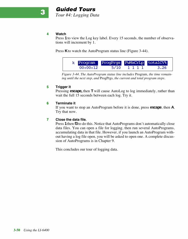
Guided ToursTour #4: Logging Data
3-50 Using the LI-6400
3
4 WatchPress 1 to view the Log key label. Every 15 seconds, the number of observa-tions will increment by 1.
Press K to watch the AutoProgram status line (Figure 3-44).
5 Trigger itPressing escape, then T will cause AutoLog to log immediately, rather thanwait the full 15 seconds between each log. Try it.
6 Terminate itIf you want to stop an AutoProgram before it is done, press escape, then A.Try that now.
7 Close the data file.Press 1 then f3 to do this. Notice that AutoPrograms donÕt automatically closedata files. You can open a file for logging, then run several AutoPrograms,accumulating data in that file. However, if you launch an AutoProgram with-out having a log file open, you will be asked to open one. A complete discus-sion of AutoPrograms is in Chapter 9.
This concludes our tour of logging data.
Program ProgPrgs FwMxCrLp totalCV%k00:00:12 5/10 1 1 1 1 3.26
Figure 3-44. The AutoProgram status line includes Program, the time remain-ing until the next step, and ProgPrgs, the current and total program steps.

Guided ToursTour #5: Configuration Adventures
Using the LI-6400 3-51
Tour #5: Configuration AdventuresThis tour will acquaint you with the Configuration Menu. While Chapter 16describes the LI-6400 configuration scheme in detail, this tour serves as ahands-on introduction to the topic.
WeÕll take you through three fairly common tasks for which you need theConfig Menu: building a configuration, checking to see what accessoriesÕcalibrations have been installed, and defining a quantity that we wish to havecomputed.
If you arenÕt already in the Config Menu, go to OPENÕs Main Screen andpress f2.
Configuring for ConifersSuppose you wish to measure pine needles instead of broadleaves. Thisbrings up several configuration issues:
¥ Leaf AreaYou probably wonÕt be using 6 cm2 for leaf area, so at the very least, youÕllhave to remember to set the area to your best estimate of what the needle areareally is. ItÕs easy to enter a value: thereÕs a function key in New Measure-ments mode for that.10
¥ Boundary Layer ConductanceThe default configuration uses a lookup table based on leaf area and fanspeed, but that table is appropriate for broadleaves, not needles.
¥ Leaf TemperatureItÕs very difficult to get the thermocouple to make good contact with a needle.YouÕll be better off using the leaf temperature thermocouple to measurechamber air temperature, and compute needle temperature based on an ener-gy balance.
How do you get all of this to happen? The simplest method is to use the In-stallation Menu:
■■■■ Build An Energy Balance Configuration File:
1 Select ÒInstallation MenuÓHighlight it, and press enter.
10.On the other hand, determining needle area is not so easy.

Guided ToursTour #5: Configuration Adventures
3-52 Using the LI-6400
3
2 Select the appropriate chamberLetÕs make this configuration for the standard 2x3 chamber (clear top, opaquebottom), so select ÒStd 2x3 Chamber TopÓ, and press enter.
3 Is the calibration entered? YesYou will be shown a list of installed chamber tops (anything having a serialnumber that begins GA- or GB-), and asked if the one you want is in the list.At the very least, there will be a GA- entry for your standard 2x3 chamber top,so just press Y.
4 Build a configuration file? YesYou will be asked if you wish to build a configuration file, and of course wedo, so press Y again.
5 Select a chamber bottomYouÕll get a menu of the two chamber bottoms that fit the 2x3 chamber: theclear bottom, and the opaque bottom. Highlight the ÒStd 2x3 Opaque Bot-tomÓ entry, and press enter.
6 Pick the light sourceHighlight the ÒSun+SkyÓ entry, and press enter.
7 Pick the chamber top (if more than one)If you have more than one chamber top (that is, a GA- or GB- calibration) in-stalled, youÕll be asked to pick which one youÕll be using. (This step isskipped if thereÕs only one calibration to choose from, or if you picked anLED light source for Step 6.)
8 Press E for Energy BalanceWhen prompted
Leaf Temperature:Measured or Energy Balance? (M/E)
press E.
9 Press N for NeedlesWhen prompted
Enter leaf typeNeedles or Broadleaves (N/B)?
press N.

Guided ToursTour #5: Configuration Adventures
Using the LI-6400 3-53
10 Admire your workYouÕll next be shown the configuration file, which should appear as inFigure 3-45. Press escape when done viewing the file.
11 Press Y to save the fileAfter you press escape, you are asked if you wish to store this configurationfile. Press Y.
12 Name the fileThe default name for this file will be
2x3 Opaque Needles EB
Modify the name if you like (press labels to access the line editing functionkeys), then press enter.
13 No more configurationsPress N when asked if you wish to build another configuration.
CalParGaAs= 0.77 // GA_103 20 Jan 1995BLCond= 5AREA= 2LightSource= "Sun+Sky" 1.0 0.19ComputeList= "Default using EB"Displays= "Std+EBTleaf"LogFormat= "Std+EB"
Which chamber top (and light sensor)
Use a fixed boundary layer conductance, instead of a lookup table.
Default leaf area
Proper light source is im-portant for the energy bal-ance computation
The standard equation set for photo, cond, etc., but computes leaf temp from an energy balance. This new variable is called EBTlf.
Display set modified to include EBTlf.
Items to be logged modified to include EBTlf.
Figure 3-45. The configuration file specifies changes to the default configuration. For information on where theboundary layer and area settings come from, refer to Installation Menu: Behind the Scenes on page 16-10.

Guided ToursTour #5: Configuration Adventures
3-54 Using the LI-6400
3
14 Read the messageA message (Figure 3-46) indicating what you have to do to actually imple-ment this new configuration is shown. WeÕll do this next. Press enter or es-cape to clear it.
15 Return to the Config MenuPress escape until you are back in the Config Menu.
■■■■ To Implement Our New Energy Balance Configuration File:
1 Select the Reset MenuHighlight Ò_Reset MenuÓ, and press enter.
2 Select ÒReset to User ConfigurationÓHighlight that entry, and press enter.
3 Select the configurationAfter a few seconds, youÕll be shown a list of configuration files (there mightonly be ÒFactory DefaultÓ and Ò2x3 Opaque Needles EBÓ. Highlight the lat-ter, and press enter.
4 View the new variable EBTlfPress escape until you get to OPENÕs Main Screen, then go to New Measure-ments mode, and press H. The computed leaf temperature will be labelledEBTlf, and the variable Tleaf¡C will be chamber air temperature. (When usingthis configuration, be sure to pull the thermocouple down a bit so it does notcontact the leaf, but measures air temperature in the chamber instead. Thiswill differ from the standard Tair_C, since that is air temperature in the sam-ple cell of the IRGA, not the leaf chamber.)
If you wish now to reset to the default configuration, do so by going to theReset Menu, and selecting ÒReset to Factory DefaultÓ.
To implement any new configthat you might have created,select if by Config Menu Õ_Reset MenuÕ ÕReset to User ConfigurationÕ
Figure 3-46. Building a configuration file doesnÕt actuallyimplement it. To do that, you select it when OPEN firstruns, or else do a reset and select it then.

Guided ToursTour #5: Configuration Adventures
Using the LI-6400 3-55
What Calibrations Are Installed?A number of the LI-6400Õs optional chambers and accessories have calibra-tions associated with them. If they were purchased along with your LI-6400,then their calibrations will likely have already been entered into the consoleat the factory. Otherwise, youÕll have to do it yourself, using the InstallationMenu. How can you tell what calibrations are installed?
■■■■ To Determine What Calibrations Are Installed:
1 Access the Installation MenuHighlight it, and press enter.
2 Select ÒView Installed Cal ItemsÓPress end then to highlight it, and press enter.
3 View the listAfter a few seconds, youÕll see a list that looks something like Figure 3-47. Itwill include the three classes of light sensor calibrations.
4 Return to the Config MenuPress escape until you get there.
A step-by-step example of how to install a 6400-02B Light Source starts onpage 16-5.
User Defined EquationsThe final stop on our configuration tour will be to view the user defined equa-tions. Chapter 15 covers this topic in detail.
6400-02 & -02B LED(s)...(CalParLED=) -.55 // SI-501 11 Aug 1997 0.48 // SI-118 03 May 1995Chamber Light Sensor(s)..(CalPARGaAs=) 0.77 // GA-103 20 Jan 1995Extrnl Quantum Sensor(s)..(CalPAROut=) 5.78 // Q13436 27 Aug 1990
Installed OptionsAll 6400-02 and -02BÕs, includ-ing serial number and calibra-tion constants.
All GA- and GB- sensors. This includes any chamber top hav-ing a GaAsP sensor.
All external quantum sensors, which are the traditional LI-COR PAR sensors.
Figure 3-47. The installed options includes the three classes of light sensors: LED sources, GaAsP detectors,and traditional quantum sensors.

Guided ToursTour #5: Configuration Adventures
3-56 Using the LI-6400
3
■■■■ View / Edit The User Defined Variables
1 Access the Ò_ComputeList MenuÓHighlight Ò_ComputeList MenuÓ in the Config Menu, and press enter.
2 Select ÒEdit Current ComputeListÓHighlight ÒEdit Current ComputeListÓ, and press enter.
3 View the listYouÕll be looking at a file much like The Default ComputeList onpage 15-16. Use the cursor control keys to navigate around in the file.
4 Add a new computationJust for the exercise, letÕs add a quantity that is photosynthetic rate inmg CO2 dm-2 hr-1. (To get that from µmol CO2 m-2 s-1, multiply by 1.584.)
To do this, locate the cursor below the definition of item #30. Then press en-ter to insert a new line, and type the new definition (Figure 3-48).
5 Store the file under a new nameWhen your file looks like Figure 3-48, press escape to view the exit menu,then press S to store this under a new name. The Standard File Dialog willappear with the current name in the edit box. Append the word TOUR to thename, and press enter.
##30 "Photo" "Photosynthesis (umol/m2/s)" " -#10 * co2_diff_um - co2_2_um * #20"_##35 "CndCO2" "Total Conductance to CO2" " 1.0 / (1.6 / #23 + 1.37 / condBL_mol)"
Figure 3-48. Adding a new equation: ItÕs ID number is 31, the label is P_gdd, itÕs description is ÒPhotogm/dm2/dÓ, and itÕs equation is photosynthesis times a constant.
Step 1: Put the cursor here.
##30 "Photo" "Photosynthesis (umol/m2/s)" " -#10 * co2_diff_um - co2_2_um * #20"
##31 "P_gdh" "Photo gm/dm2/hr" "#30 * 1.584"
##35 "CndCO2" "Total Conductance to CO2" " 1.0 / (1.6 / #23 + 1.37 / condBL_mol)"
Step 2: Press enter, type in this line, and press enter again.
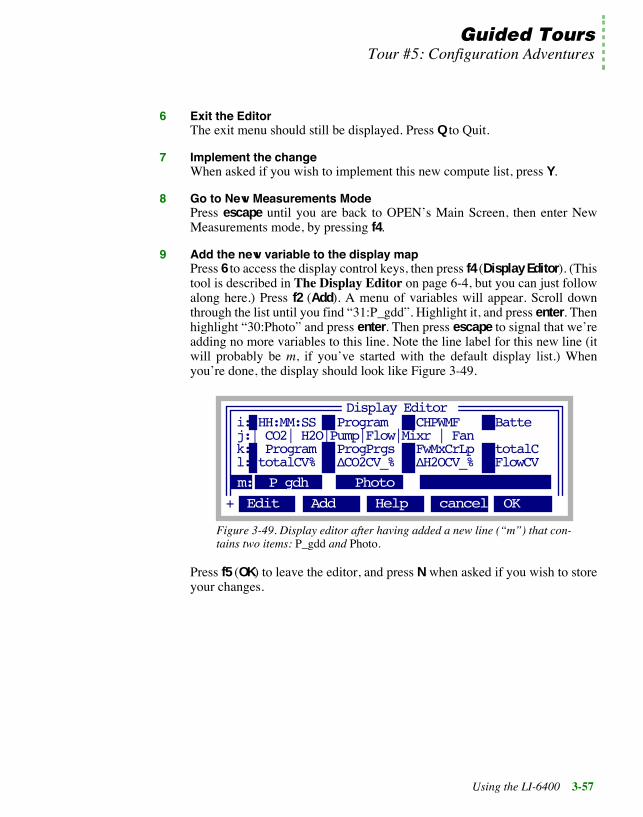
Guided ToursTour #5: Configuration Adventures
Using the LI-6400 3-57
6 Exit the EditorThe exit menu should still be displayed. Press Q to Quit.
7 Implement the changeWhen asked if you wish to implement this new compute list, press Y.
8 Go to New Measurements ModePress escape until you are back to OPENÕs Main Screen, then enter NewMeasurements mode, by pressing f4.
9 Add the new variable to the display mapPress 6 to access the display control keys, then press f4 (Display Editor). (Thistool is described in The Display Editor on page 6-4, but you can just followalong here.) Press f2 (Add). A menu of variables will appear. Scroll downthrough the list until you find Ò31:P_gddÓ. Highlight it, and press enter. Thenhighlight Ò30:PhotoÓ and press enter. Then press escape to signal that weÕreadding no more variables to this line. Note the line label for this new line (itwill probably be m, if youÕve started with the default display list.) WhenyouÕre done, the display should look like Figure 3-49.
Press f5 (OK) to leave the editor, and press N when asked if you wish to storeyour changes.
i: HH:MM:SS Program CHPWMF Battej:| CO2| H2O|Pump|Flow|Mixr | Fank: Program ProgPrgs FwMxCrLp totalCl: totalCV% ÆCO2CV_% ÆH2OCV_% FlowCV
m: P_gdh Photo
Display Editor
Edit Add Help cancel OK+
Figure 3-49. Display editor after having added a new line (ÒmÓ) that con-tains two items: P_gdd and Photo.

Guided ToursTour #5: Configuration Adventures
3-58 Using the LI-6400
3
10 View Photo and P_gddd.When you are back in New Measurements mode, press M (or whatever thelabel is for the line youÕve added), and you should see your new quantity,along with Photo (Figure 3-50).
11 Return to normalWeÕll finish our configuration tour by resetting the instruments back to thefactory configuration (or, to a configuration of your choice). Access the ResetMenu (in the Config Menu), and select either ÒReset to Factory DefaultÓ, orÒReset to User ConfigurationÓ. If you do the latter, then select ÒFactory De-faultÓ from the list of configurations, itÕs equivalent to doing the former.
Photo Cond Ci Trmmol
1.95 1.23
-0.233 0.101 499.5 40.09
1.23 0.0141 438 0.119
ÆCO2_µml ÆH2O_mml Flow_µml RH_S %
P_gdh Photo
Open <view <close <add MatchLogFile file> file> remark>
m
b
c
1
®
Figure 3-50. The new variable was added to display line m, along withphotosynthesis.

Guided ToursTour #6: Boot Screen and LPL
Using the LI-6400 3-59
Tour #6: Boot Screen and LPLIf you hold the opinion that computers are a necessary evil, and try to avoidthem as much as possible, then feel free to skip this tour and proceed toChapter 4.
This tour takes you backstage for a glimpse of what goes on there. You wonÕtsee curtains and scenery, but you will see a few layers of software(Figure 3-51).
Boot
LPL
/sys/autost
/sys/open/open
/sys/open/start
The Boot program launches the LPL op-erating system when you power on, un-less escape is held down.
LPL runs programs that reside in the file system. When it starts up, however, LPL looks for a specific file (/sys/autost) to run, if it exists.
The default /sys/autost runs /sys/open/start, which scans the file system, and asks if the chamber/IRGA is connected, then runs /sys/open/open.
OPEN launches many applications, such as AutoPrograms, calibration pro-grams, and various editors.
Figure 3-51. A depiction of software layers in the LI-6400. There are three main ones: 1) Boot code, 2) LPLoperating system, and 3) LPL programs. LPL programs can run other programs, so multiple layers of them canbuild up. An AutoProgram, for example, represents a 4th layer of LPL program.
?
Press ctrl + escape to abort an applica-tion. Eventually, youÕll be back to the LPL Screen. To drop all the way back to the Boot Screen, press ctrl + shift + escape.

Guided ToursTour #6: Boot Screen and LPL
3-60 Using the LI-6400
3
The Boot ScreenThe first stop on the tour will be the Boot Screen, which is the human inter-face of the lowest level program in the LI-6400.
■■■■ Accessing the Boot Screen
1 escape + power on, or else ctrl shift escape.If the LI-6400 is off, hold the escape key down, and turn on the power switch.If power is on, then you can simultaneously press ctrl + shift + escape.
Three typical reasons for accessing this screen are 1) setting the default dis-play contrast, 2) setting the default baud rate, or 3) installing new software.When you connect a DOS or Windows computer and run the 6400-50 instal-lation program (INSTALL.EXE), you must be in the Boot Screen, and theprogram will make use of the Upload option.
More details are provided in The Boot Screen on page 5-18.
2 Make sure Debug is OFFIf Debug is ON, press D to toggle it to OFF, then press S to save the configu-rations. Debug is used for testing, and having it on will slow some operationsnoticeable, especially those relating to the file system.
3 Run the ApplicationAs far as the boot code is concerned, the LI-6400 has but one application pro-gram, and it runs when you press R. Do that now.
4 Be ready to press escapeWhen you see
Is the chamber/IRGA connected? (Y/N)
Welcome to LI-6400(R)un(U)pload(C)heck CRC(B)ps = 115200(T)erminal
Select:_
(V)oltages(S)save parms(+/-/UP/DOWN) contrast(D)ebug: OFF
Figure 3-52. The boot screen.

Guided ToursTour #6: Boot Screen and LPL
Using the LI-6400 3-61
press escape. (ItÕs possible for other messages to come up before this that re-quire you to press enter to continue on. These are described in Power On /Start-up Problems on page 20-2).
You should now be viewing the LPL Screen (Figure 3-53), our second stopon the tour.
The LPL ScreenLPL stands for LI-COR Programming Language, and its description starts inChapter 22. The application that we ran back in Step 3 is the LPL OperatingSystem.
The user interface to LPL is the LPL Screen (Figure 3-53), which allows youto edit files, access the Filer, enter File Exchange Mode, run LPL programs,or execute LPL commands from the keyboard. For details, see The LPLScreen on page 5-20.
For this tour, weÕll perform a series of tasks to demonstrate what can be donefrom this level.
■■■■ View Data Files from LPL
1 Access the FilerPress F.
2 Highlight the file to be viewed.Press D and select the /User directory, and then highlight a data file.
Editor Filer Run Shell Xchng
LPL 3.3.008Copyright 1995 - 1999 LI_COR, inc.
/ 409616 bytes
Current working directory Available memory
Figure 3-53. The LPL Copyright screen.

Guided ToursTour #6: Boot Screen and LPL
3-62 Using the LI-6400
3
3 View the FilePress V. Or, press labels a couple of time, then press f1 (View). The file willbe read and shown to you. You can scroll around in it, then press escape toleave it.
4 Plot the dataHighlight the file to be plotted, and press H. The message
Including librariesÉ
will be displayed for several seconds, then GraphIt is run. (When you runGraphIt from OPEN, you donÕt have to wait for the libraries to be loaded; thathappened when OPEN was loading.)
5 Press escape to leave GraphIt
6 Plot a different fileHighlight another file, and press H again. This time, GraphIt is accessed im-mediately, because its libraries remain loaded, and will until you leave theFiler.
7 Return to the LPL ScreenPress escape until you get there.
■■■■ Write and Run an LPL ProgramThe LPL program youÕll see the most is OPEN. The file system contains anumber of other programs, however, that donÕt require OPEN. What weÕll donow is have you write a simple program, then run it.
1 Press E to access the EditorThis editor is described in Standard Edit on page 5-13.
2 No file nameYouÕll be asked
Edit What File: /SYS/AUTOST
Press f1 (DelLn) to clear the file name, and press enter. YouÕll be editing anew (empty) file.
Time-Saving Hint:Some file related tasks (plotting, viewing, downloading, etc.) do not re-quire that OPEN be loaded; you can do them from the LPL screen.

Guided ToursTour #6: Boot Screen and LPL
Using the LI-6400 3-63
3 Enter a programType the following
:fct main {"Hello there" print getkey }
4 Run the programPress escape to view the exit menu, followed by X, to run the file you justtyped.
Hello there
will be printed, and the LI-6400 will wait for you to press a key. Press enterand youÕll return to Standard EditÕs exit menu.
5 Save the programFrom the exit menu, press S, and use the Standard File Dialog to name the fileHello, and put it in the directory /User. To specify the directory user (if itÕs notalready selected), press f1 (Dir) and pick it.
6 Return to the LPL ScreenFrom the exit menu, press Q.
7 Run your program againPress R, and enter
/user/hello
Your program should run again. Press enter to end it.
■■■■ Run another programLetÕs run a slightly more useful program from the LPL screen.
1 Press RYouÕll be asked for a file name, and the default will be the last one you en-tered.
2 Use the wild card featurePress DelLn to clear the file name, and enter
/sys/utility/*

Guided ToursTour #6: Boot Screen and LPL
3-64 Using the LI-6400
3
This will provide a list of all files in the /sys/utility directory. You can selectone to run from the list (Figure 3-54). By the way, these programs are de-scribed in /Sys/Utility Programs on page 21-10.
3 Select "Geopotential"This program displays the pressure sensorÕs reading, and computes geopoten-tial height. (It is documented on page 21-16.) It can also be run from OPENÕsTests & Diagnostics Menu, found in the Welcome Menu (Figure 3-5 on page3-8).
While this program is running, lift the console. You should be able to see theindicated height above sea level (in an idealized atmosphere) change.
4 QuitPress escape to exit the program, and return to the LPL Screen.
■■■■ Launch OPEN from LPLNow, letÕs run a familiar program from the LPL Screen: OPEN.
1 Press RYouÕll be asked for a file name.
2 Enter OPENÕs name and directoryPress f1 if necessary to clear the line, and type
/sys/open/open
and press enter. YouÕll see the familiar bar chart displayed, as OPEN loads.
3 Interrupt itPress escape to stop OPEN from loading, and press escape again to return tothe LPL Screen.
"BoardsON" 709 940804 15:42:26"ENERGYBAL" 2606 941221 09:55:28
"Graphics Capture" 752 970905 14:10"Graphics Restore" 817 950622 09:45"GraphIt Utility" 1017 970409 12:54
"BoardsOFF" 711 940808 15:42:46/sys/utility/*
"Geopotential" 2531 941207 10:32:34
Figure 3-54. Selecting the program Geopotential from a menugenerated by entering a wild card for the file name.

Guided ToursTour #6: Boot Screen and LPL
Using the LI-6400 3-65
This brings up the question, what really happens when you power on to makeOPEN load automatically? The answer (Figure 3-51 on page 3-59) involvesthe autost file.
■■■■ Examining /Sys/AUTOSTWhen LPL is launched, it looks for a file named /sys/autost. If it finds it, it runsit. Otherwise, it displays the LPL Screen and waits for the user to do some-thing.
1 View /sys/autostFrom the LPL Screen, press E. When asked for a file name, press f1 (DelLn),then type /sys/autost and press enter.
You will see
:FCT main { "/sys/open/startÓ RUN }
which means the only thing this program does is run another program named/sys/open/start.
2 View /sys/open/startPress escape then Q to stop viewing /sys/autost, and press E, then f1 (DelLn),change the name to /sys/open/start, and press enter.
This is the program (Figure 3-55 on page 3-66) that prompts you for
Is the chamber/IRGA connected?
if the IRGA or flow board is turned off, and then scans the file system (theScanDirs function) before launching /sys/open/open.
3 Return to LPL ScreenPress escape, then Q.
WeÕre done. If you would like to pursue programming in LPL, youÕll find atutorial and reference in this manual, starting in Chapter 22.

Guided ToursTour #6: Boot Screen and LPL
3-66 Using the LI-6400
3
/*
Start
Launches OPEN
*/:INT abortFlag 0:FCT main{
0x0301 DIOGET0x0302 DIOGETOR NOT IF
"\fIs the Chamber/IRGA connected ? (Y/N)" PRINT&keys ONKBD5 TIDLEOFFKBD
THENCLEARabortFlag IF RETURN THEN
ScanDirs /* helps prevent defragmentation */
"/Sys/Open" DIRSET"/Sys/Open/Open" RUN
}
Keys{
GETKEY UPC :INT cc 0x1b == IF 1 &abortFlag = THENc 'Y' == IF
1 0x0301 DIOSET1 0x0302 DIOSET
THENHALT
}
ScanDirs{
1000 OPEN_BUFF IF RETURN THEN:PTR buff buff DIRALLbuff CLOSECLEAR
}
Figure 3-55. Listing of /sys/open/start, which ultimately launches /sys/open/open.
Get flow and analyzer board status
If either are off, ask if they can be turned on
Scan the file system, get directory list
Set current working directoryRun OPEN
This function called when user presses a key
Get the key, see what it was
If an escape, abortIf the Y key, turn on the boards
For 5 seconds, wait for a key stroke
Open a buffer
Get the list of directoriesClose the buffer

Using the LI-6400 4-1
4Making Measurements
The fundamentals of good measurements
PREPARATION CHECK LISTS 4-2During Warm Up 4-3After Warm Up 4-4Clamping Onto the First Leaf 4-6
SOME SIMPLE EXPERIMENTS 4-8Humidity Control Experiments 4-9Controlling CO2 4-12Light Experiment 4-16Where to Go From Here 4-20
MAKING SURVEY MEASUREMENTS 4-21Operational Considerations 4-21
LIGHT RESPONSE CURVES 4-24Light Curve Strategies 4-24Operational Considerations 4-25Rapid Light Curve, Step-By-Step 4-27
CO2 RESPONSE CURVES 4-30Why Measure CO2 Response? 4-30Operational Considerations 4-30Step-By-Step 4-32
MATCHING THE ANALYZERS 4-34How to Match 4-35What Happens in Match Mode 4-36Messages in Match Mode 4-37When To Match 4-39Logging Match Adjustments 4-39Modifying the Match Display 4-40
STABILITY CONSIDERATIONS 4-41Stability Variables 4-41Real Time Graphics 4-41Average Time 4-42
LEAKS 4-42Bulk Flow Leaks 4-42Diffusion Leaks 4-43
OPERATIONAL HINTS 4-47Air Supply Considerations 4-47WhatÕs the Light Source? 4-49Dealing With Low Rates 4-49Humidifying Incoming Air 4-50Controlling Low Flow Rates 4-52
ANSWERS TO QUESTIONS 4-53

Making Measurements
4-2 Using the LI-6400
4The presentation in this chapter presumes that you have assembled theLI-6400, learned how to operate the software - especially the chamber controlfunctions - and are ready to make measurements on plants.
Preparation Check ListsWe present a checklist of things that should be done prior to making measure-ments. They take about 5 minutes, but if you are careful to do this each ses-sion, it can save you a lot of time and frustration later. You may wish to copyand clip this checklist summary:
A. During Warm Up 1) Air Supply: Prepare CO2 Mixer or Buffer Volume2) Temperatures: Values OK? Tleaf responding?3) Light Source, Sensors: Responding? Values OK?4) Pressure Sensor: Value OK? Stable?5) Leaf Fan: Running?6) Flow Control: Max flow OK? Chemical tube restrictions?
B. After Warm-up 1) Check the flow zero2) Adjust latch, close chamber3) Check CO2 zero4) Check H2O zero5) Mixer Calibration (optional)6) Lamp Calibration (optional)7) Check Tleaf zero8) Set Reference CO2 and H2O9) Test for leaks10) Match the IRGAs. Valve working?
C. Measuring the First Leaf 1) Set Light2) Set Flow to 400 µmol s-1
3) Set Reference CO24) Temperature?5) Clamp onto leaf6) Set Area and Stomatal Ratio7) Set constant humidity?
Figure 4-1. The checklists to prepare for making measurements.
✁

Making MeasurementsPreparation Check Lists
Using the LI-6400 4-3
During Warm UpOnce OPEN is loaded, and while the gas analyzers are warming up, youshould do these steps.
1 Air Supply - Cartridge or Buffer Volume?If you are going to be using the 6400-01 CO2 mixer, install a cartridge now,so the system can begin pressurizing. Otherwise, prepare a buffer volume (seeAir Supply Considerations on page 4-47).
2 Check the TemperaturesThe three measured temperatures (block, air, and leaf) are together in displaygroup h. Check to see that they read reasonable values, and are within a fewdegrees of each other.
Position the thermocouple properly, either just above the gasket(Figure 19-16 on page 19-19) for leaf measurement (normal), or pulled downfor air temperature measurement (energy balance).
3 Check the Light Source and SensorsCheck to make sure that the instrument is configured for the light source thatyou are using. See Specifying the Source and Sensor on page 8-3.
The light sensors (ParIn_µm and ParOut_µm) are both in default displaygroup g. See that they respond as expected when the light sensors are illumi-nated and darkened.
If you get negative ParIn_µm values, there is probably a mismatch betweenthe real light source, and the one OPEN thinks it has. A trip to LightSourceControl (page 8-4) will fix that.
4 Check the Pressure SensorThe pressure measurement (Prss_kPa) is shown in display group g. See thatit shows reasonable, stable values. (Typical values: 100 kPa near sea level, 97kPa at 1000 ft., 83 kPa at 5000 ft., etc., but this varies with the weather.)
5 Check the Leaf FanTurn the leaf fan off and on (f3 level 3), and listen for sound changes in thesensor head as the fan motor stops and starts. No sound when there should besound could mean a blown fuse (fan or flow board), a fan jammed with debris,or other problems (see Chapter 20). Leave the fan on when you are done.
6 Is Flow Control OK?Use the flow control key (f2 level 2) to set up fixed flow at 1000 µmol s-1.Watch the Flow_µms (display group b) to determine the actual maximum

Making MeasurementsPreparation Check Lists
4-4 Using the LI-6400
4
flow. The value is typically in the 700Õs if a CO2 mixer is installed, or higherif not.
Now test the chemical tubes for flow restrictions by changing each from fullbypass to full scrub, and watching the affect on flow rate. Normally, scrub-bing will drop the maximum flow by 5 or 10 µmol s-1 per tube. Larger dropsmay indicate that the air mufflers in the chemical tubes are getting clogged,or that a flow diversion tube is pinched shut. See Pump/Flow Problems onpage 20-13 for more details.
Finally, set the flow to 500 µmol s-1.
After Warm UpAfter the IRGAs have been on for about 10 minutes1, continue with the fol-lowing steps:
1 Check the Flow zeroIn New Measurements mode, monitor Flow_µms (display line b) and turn thepump off (2 f2 N) and the chamber fan off (3 f3 O for off)2. The flow shoulddrop to within 1 or 2 µmol s-1 of zero. If it doesnÕt, re-zero the flow meter (Ze-roing the Flow meter on page 18-17). Turn the fan back on when done.
2 Adjust the latch, and close the chamber1) Adjust the latch so that the chamber lips are slightly apart when the cham-ber is closed. 2) With the chamber closed, close the adjustment knob until itstarts to become snug. 3) Open the chamber, and turn the knob one or twomore half turns. Now the chamber is adjusted properly for sealing when emp-ty, or with thin leaves. Close the chamber for the next two steps.
3 Check the CO2 IRGA zeroIn New Measurements mode, with the mixer off (2 f3 N), and the flow set to500 µmol s-1 (f2 F 500 enter), monitor CO2 reference and sample (displayline a). Turn the soda lime on full scrub, and the desiccant on full bypass. Thereference should quickly approach zero, while the sample will approach zeroa bit more slowly. If they are within 5 µmol mol-1 of zero, it will be adequate.
1.Or longer, if the system has just been moved from one temperature to another.2.Why turn off the chamber fan? If itÕs on when the pump is off, it will actuallypush a bit of air (1 or 2 µmol s-1) back through the flow meter, throwing off yourzero reading.

Making MeasurementsPreparation Check Lists
Using the LI-6400 4-5
4 Check the H2O IRGA zeroTurn the desiccant to full scrub, and watch sample and reference H2O. Thereference will again approach zero faster than the sample does. It will zeromore slowly than the CO2 IRGA did, however, because of water sorption.Rather than wait the 10 or 20 minutes to get a really good zero, use yourjudgement. If after a minute or so, the reference is down to 0.2 or 0.3mmol mol-1 and falling slowly, thatÕs good enough. The sample will be high-er than that. Clearly, if itÕs negative and falling after only 1 minute, it will begoing too low, and re-zeroing may be in order.
If the CO2 or H2O IRGAs need zeroing, refer to Setting the CO2 and H2OZero on page 18-4. The important thing is that the reference IRGAs are rea-sonably well zeroed (letÕs say ±5 µmol mol-1 CO2, ±0.5 mmol mol-1 H2O).The first time you match (Step 10, coming up), the sample IRGAs will be tak-en care of, as they are adjusted to match the reference IRGAs.
5 Mixer CalibrationIf you are using the 6400-01 CO2 Mixer, run the calibration program de-scribed in 6400-01 CO2 Mixer on page 18-20. The chamber can be open forthis. Make sure that the soda lime is on full scrub.
6 Lamp CalibrationIf you are using the 6400-02 or -02B LED Source, run itÕs calibration, whichis described in 6400-02(B) LED Source on page 18-24. You will do the bestcalibration by having the chamber closed onto a representative (with respectto its reflectance) leaf. This isnÕt critical however, but the chamber should atleast be closed.
7 Check Tleaf zeroUnplug the leaf temperature thermocouple connector (itÕs purple colored),and compare the leaf and block temperatures. If they differ by more than 0.1¡,
Important Note about CO2 and H2O Zeros:If your chemicals are not fresh, then you will do more harm than goodby setting the zeros with them.
The IRGA zeros are quite stable, especially in the absence of big tem-perature changes. Therefore, the exercise of checking zeros each day isreally a diagnostic. If the indicated concentration doesnÕt change whenit should (that is, if it doesnÕt drop when you start scrubbing), thensomething is wrong, and itÕs good to find that out early.

Making MeasurementsPreparation Check Lists
4-6 Using the LI-6400
4
then adjust it (see Zeroing the Leaf Temperature Thermocouple on page18-19).
Finally, reconnect the thermocouple, open the chamber, and verify thatÒTleaf_¡CÓ responds when the thermocouple warmed by touching it.
8 Set Desired Reference Values for CO2 and H2OIf you are using the CO2 mixer, set it to control on reference concentration
with a target of 400 µmol mol-1. Make sure that the soda lime is on full scrub. If you are not using the CO2 mixer, monitor the reference CO2 concentration.Is CO2R_uml sufficiently stable? (Over a 30 s period, it should change lessthan 2 µmol mol-1.) If not, use a larger buffer volume.
For H2O, set the desiccant at mid-range (between scrub and bypass) for now.
9 Leaks?Set the flow rate to 200 µmol s-1. With the chamber closed and empty, exhalearound the chamber gaskets, and look for any fluctuations in the sample cellCO2 concentration (CO2S_µml, display group a). If there are no leaks, the
CO2S_µml value should not increase by more than 1 µmol mol-1.
10 Match the IRGAsMatching the IRGAs is easily accomplished whether the chamber is empty ornot, but itÕs good policy to do this once right before starting a measurement.Refer to Matching the Analyzers on page 4-34 for how to do this.
Verify that the match valve is in fact working. Figure 4-4 on page 4-35 showswhat to look for.
You are now ready to clamp onto a leaf and begin measurements.
Clamping Onto the First LeafOnce youÕve got the system behaving well with no leaf in the chamber, youare ready to start. The basic procedure is quite simple: set initial conditions inthe chamber, put a leaf in the chamber, and do a final adjustment if necessaryso that you have the conditions in the chamber that you want, then wait forthings to stabilize.
1 LightIf using the LED source, set the light to the desired value (ambient is a goodvalue to start with - it wonÕt be an abrupt change for the leaf). If you arenÕt

Making MeasurementsPreparation Check Lists
Using the LI-6400 4-7
using the LED source, then orient the chamber so that no shading of the leafby the chamber walls will occur once youÕve installed the leaf.
2 FlowSet the control for Fixed flow, about 400 µmol s-1, desiccant mid-range be-tween scrub and bypass. WeÕll come back to this in Step 7.
3 CO2If you are using the CO2 mixer, set it to control reference CO2 with a target a
bit above ambient conditions (say, 400 µmol mol-1). If you arenÕt using theCO2 mixer, but using a buffer volume instead, set the soda lime scrub knobto give you the concentration you want. Usually, that means full bypass.
4 Temperature(Optional) If you are going to be in direct sun, you will probably want to usethe coolers to control the temperature. Check the temperatures to see theirpresent values, then set the control accordingly.
5 Insert leafCheck the latch adjustment for a good seal. Snug is fine; be careful itÕs nottoo tight, however. If you arenÕt using the LED source, be careful with thechamberÕs orientation; avoid shading part of the leaf with the walls of thechamber.
6 Set Area and Stomatal RatioIn New Measurements mode, press 3, and set the leaf area and stomatal ratiofor this leaf. Leaf area is simply the area exposed inside the chamber. If youare using a 2x3 chamber and filling it, the area is 6 cm2. Stomatal ratio is anestimate of the ratio of stomata on one side of the leaf to the other. Use 1 forequal stomatal density on top and bottom; 0 for stomata on only one side. Ifyou arenÕt sure, use 0.5. It doesnÕt matter if you use the ratio of top to bottom,or bottom to top. Thus, 0.5 is the same as 2; 0.333 is the same as 3, etc.
7 Revisit the flow controlDecide how you will operate: control flow to maintain constant humidity, orrun at a constant flow. (If you arenÕt sure what to do here, you probablyskipped over Tour #3: Controlling Chamber Conditions on page 3-20.There may still be hope for you, however; work through Humidity ControlExperiments on page 4-9.)
From this point on, what you do is going to depend on your experiment, orwhat it is you wish to accomplish. For example, you might wish to measure aresponse curve (light, for example, is discussed on page 4-24), or make sur-

Making MeasurementsSome Simple Experiments
4-8 Using the LI-6400
4
vey measurements (page 4-21), going from leaf to leaf and only taking aminute or so to get each measurement.
If you are new to gas exchange measurements on plants, continue on with thenext section (Some Simple Experiments). It will take you through somethings to look for to make sure you are making a valid measurement.
Some Simple ExperimentsIf you have not had much experience making gas exchange measurements be-fore, you may wish to work through some of the experiments in this section.To do any of them, however, first get a leaf established in the chamber:
■■■■ Do this first
1 Select a plant and leaf to measureThe easiest measurement will be on an adequately watered plant that is grow-ing in full or partial sun. By contrast, a difficult measurement will be on a dry,neglected house plant that has only seen dim (for the plant) fluorescent lightsits whole life. Try to find something more like the former than the latter.
2 Do Steps 1 through 6 in the previous sectionThis will take you through getting the leaf into the chamber.
3 Observe the CO2 concentrationsNote CO2S_µml. Is it below CO2R_µml? If so, thatÕs good, because it meansphotosynthesis is occurring. (Photosynthetic rate will be on display line c, un-der Photo.) Is CO2S_µml stable (within 0.2 or 0.3 µmol mol-1)? It should sta-bilize after 30 seconds or so of clamping onto the leaf. If itÕs not stable, checkCO2R_µml for stability. Perhaps the mixer isnÕt stabilized yet, or you need abuffer volume. Consult Unstable Photosynthetic Rates on page 20-10, ifyou need help fixing this instability. If CO2S_µml is not below CO2R_µml,then perhaps you need to match (page 4-34).
4 Observe the humidity valuesThe RH_S_% value on display line b is the relative humidity in the sampleIRGA. ItÕs calculated from the water IRGA signal, which is H2OS_mml. Oth-er things being equal, you want to make gas exchange measurements in ashigh a humidity as possible, without letting the flow rate (which is determin-ing that humidity) go too low. 200 or 300 µmol s-1 is a reasonably low flowrange; but you can drop to 100 if you need to. (Leaks are a bigger problem atlow flow rates - see Leaks on page 4-42.)
You are now ready to do some or all of the following elementary experiments.

Making MeasurementsSome Simple Experiments
Using the LI-6400 4-9
Humidity Control ExperimentsStep 7 on page 4-7 (Revisit the flow control) asks you to decide how youwish to operate while making measurements: either a fixed flow rate (with apotentially variable humidity), or constant humidity (with a potentially vari-able flow rate). The following experiment will acquaint you with the capabil-ities and trade-offs involved.
Experiment #1 Finding the Humidity LimitsIf you are using the CO2 mixer, set it to control the reference concentration at
a value slightly above ambient, such as 400 µmol mol-1 if youÕre outdoors.
1 Operate in fixed flow modeWith the desiccant midway between scrub and bypass, operate in a fixed flowmode at 400 µmol s-1.
2 Match the IRGAsWhen CO2S_µml and H2OS_mml become stable, match the IRGAs.
3 Note the conditionsAfter matching, note the values that pertain to photosynthesis (CO2R_µml,CO2S_µml, DCO2, and Photo) and the values that pertain to conductance(H2OR_mml, H2OS_mml, RH_S_%, and Cond).
4 Find the upper humidity limitSet the desiccant on full bypass, and the flow rate to 100 µmol s-1. Wait aboutone minute, then observe the water numbers. The value of H2OS_mml will beabout as high as youÕll be able to achieve with this leaf at this stomatal con-ductance.
Question #1: How can the RH_S_% value (as opposed to H2OS_mml) befurther raised and lowered? (Answer on page 4-53.)
Note that we just dropped the flow rate F by a factor of 4 for this step. Since and (the complete equations for photo-
synthesis A and transpiration E are in Chapter 1) it might lead you to believethat DCO2 and DH2O should each have also increased by a factor of 4.
Question #2: Did you observe a 4-fold increase in DCO2? How aboutDH2O? If you didnÕt, why not? (Answer on page 4-53.)
5 Find the lower humidity limitNow set the desiccant on full scrub, and increase the flow to 800 µmol s-1 (itprobably wonÕt achieve that value). Give it a minute or so to stabilize, and ob-
A CO2D( ) F¤= E H2OD( ) F¤=

Making MeasurementsSome Simple Experiments
4-10 Using the LI-6400
4
serve the new set of values. This H2OS_mml value represents your lower hu-midity limit for this leaf.
How is stomatal conductance (Cond) behaving: steady, dropping, or increas-ing?
Question #3: We just lowered the humidity in the chamber. If there are watersorption effects on the chamber walls, will they make stomatal conductancetoo high or too low? (Answer on page 4-53.)
Question #4: How might you differentiate real stomatal changes from watersorption effects? (Answer on page 4-53.)
6 Return to starting ConditionsReturn the flow to 400 µmol s-1, and the desiccant to mid-range betweenscrub and bypass.
Experiment #2 Maintaining a Constant HumidityOften it is desired to make measurements or to conduct an experiment at aconsistent chamber humidity. This experiment lets you see the automatic hu-midity control in action.
1 Pick a humidity targetStart out in fixed flow mode at 400 µmol s-1, with the desiccant adjustmentknob midway between scrub and bypass.When H2OS_mml is stable, changeto constant humidity control (use the H option: constant H2O mole fraction),and target that current value of H2OS_mml. Your flow rate should settle intothe 300 or 400 µmol s-1 range. (If flow jumps to either extreme, and you startseeing flashing messages about targets being too dry or too wet, make sureyou selected the H option, and entered a reasonable value in mmol mol-1.)
Note the CO2S_µml value.
Points to Remember¥ Changing the flow rate affects both CO2 and H2O concentration in thechamber.
¥ Chamber humidity control is via flow rate. The highest humidity isachieved by low flow and bypassing the desiccant. The lowest humidity isachieved by high flow and full scrub.

Making MeasurementsSome Simple Experiments
Using the LI-6400 4-11
2 Dry the incoming airOnce the chamber humidity is on target, and the flow rate is stable, turn thedesiccant knob to full scrub. Observe what happens to reference humidity,flow rate, and sample humidity (H2OR_mml, Flow_µml, and H2OS_mml).Reference humidity should go to zero, flow will decrease, and H2OS_mmlwill remain unchanged. Also, keep an eye on how quickly or slowlyCO2S_mml gets to itÕs new value.
Question #5: What does it mean if the reference humidity (H2OR_mml)doesnÕt get within 0.5 mmol mol-1 of zero? (Answer on page 4-53.)
Question #6: Will the sample cell CO2 (CO2S_µml) increase or decreaseduring this step? Why? (Answer on page 4-53.)
3 Moisten the incoming airNow turn the desiccant knob to full bypass, and watch the flow increase, ref-erence humidity increase, and the sample cell water mole fraction remain un-changed. The sample cell CO2 will go the other direction from how itchanged in the previous step (not to give the answer to Question #6 awayÉ).
4 Change to constant RHReturn the desiccant knob to midway, and after the flow rate stabilizes, notethe value of RH_S_%. Now change to constant RH control, and target thatvalue of RH_S_%.
5 Turn on the coolersTurn on the temperature controllers (f4 level 2), and set the block temperaturefor a target about 5¡C below itÕs present value (display line h). But, beforeyou do this, try another question:
Question #7: What will cooling the chamber do to flow rate (owing to theconstant RH control mode) and why? (Answer on page 4-53.)
6 Watch RH and flowAs the air temperature drops in the chamber, watch the flow compensate forthe changing RH. Notice that it is not quite as tight a control as when we werecontrolling on a constant mole fraction; RH will drift off target a little bit asthe temperature changes. (Why? Read about it in R) Constant RH on page7-10.)
7 Change to constant VPDNote the current value of VpdA (display line d), the vapor pressure deficitbased on air temperature. Then change to controlling to a constant VPD,based on Tair, and target that value. (See V) Constant VPD on page 7-10.)

Making MeasurementsSome Simple Experiments
4-12 Using the LI-6400
4
8 Change the temperature control to ambient + 5¡CBefore you do, test your understanding with this question:
Question #8: How will flow rate respond as the temperature increases, sinceweÕre holding a constant vapor pressure deficit? (Answer on page 4-53.)
Now try it, and see who is correct. Wait 2 or 3 minutes for things to stabilize.
9 Watch it warmYou might notice that warming is more efficient than cooling. You may alsonotice that the VPD gets away from the target a little bit as the temperaturechanges.
When the block temperature achieves its target, see that the VPD settles backto itÕs target. Then set the target temperature to ambient, and bring the cham-ber back to normal.
You can turn the temperature control off if you like.
Controlling CO2The next two experiments are best done with a 6400-01 CO2 mixer. If youdonÕt have one installed, you can still do approximate CO2 control betweenambient and zero by adjusting the soda lime tube flow adjust knob.
Experiment #3 CO2 and Humidity Control InteractionsStart with the conditions described by Do this first on page 4-8. Make surethe desiccant knob is mid-range.
1 Set flow control for constant water mole fractionTarget the current value of H2OS_mml (Step 1 on page 4-10).
Points to Remember¥ Constant humidity mode will compensate for changes in incoming airstream, or leaf transpiration changes.
¥ Controlling to a constant mole fraction is the tighter control, while con-trolling to a constant RH or VPD can have small lags in the face of rapidlychanging temperature (see the discussion about the various humidity con-trol options on page 7-10 for more details).

Making MeasurementsSome Simple Experiments
Using the LI-6400 4-13
2 Change to constant sample cell CO2If you have a CO2 mixer, switch over to controlling a constant sample cellconcentration. Target the present value of CO2S_µml. Wait for CO2S_uml tostabilize.
3 Turn the desiccant knob to full scrubWatch CO2R_µml and CO2S_µml. The latter is supposed to be held constant.CO2S_µml will drift well off target, then come back to where it was asCO2R_µml adjusts.
Question #9: Will CO2R_µml increase or decrease? (Answer on page 4-54.)
Note: Keep in mind that this test of abruptly changing the incoming humiditywhile trying to control both chamber humidity and CO2 is an artificial worstcase. More typically, the flow control system is balancing stomatal changes,which happen much less rapidly, so the sample cell CO2 control option isnÕtfaced with large swings in flow rate. The next two steps will illustrate a moretypical sequence of events.
4 Return the desiccant knob to mid-rangeWatch the sequence reverse itself. Also note the order in which things hap-pen: Once Flow_µml stabilizes, then CO2S_µml can stabilize.
5 Shade the leafIf you are using a light source, cut the light value in half. If you are not, justshade the leaf with your hand. Before you do, however, hereÕs another learn-ing opportunity:
Question #10: What do you expect to happen to photosynthesis (Photo), sto-matal conductance (Cond), and intercellular CO2 (Ci) when you cut the lightin half? How do you expect the control systems to compensate: specifically,how will flow rate change, and how will reference CO2 change? (Answer onpage 4-54.)
6 Watch the responsePhotosynthesis will immediately start to drop, and (if you wait 10 or 15 min-utes), conductance will eventually decrease as well.

Making MeasurementsSome Simple Experiments
4-14 Using the LI-6400
4
7 Restore the lightReturn the leaf to itÕs original light value, and watch the control systems re-spond again to the changes.
Experiment #4 A Manual CO2 Response CurveCO2 response curves are described in detail later (page 4-30), including howto generate them automatically. This experiment will give you a step-by-stepguide to generating one by hand. If you donÕt have a CO2 mixer, donÕt de-
spair3, you can still do the experiment.
As always, we start with the conditions that Do this first on page 4-8 de-scribes.
1 Set the controlsFlow: Constant mole fraction, target the current value (Step 1 on page 4-10).CO2: If you have a CO2 mixer, set it to control reference CO2 to a bit above
ambient, such as 400 µmol mol-1. If you donÕt, set the soda lime knob on fullbypass.Temperature Control: Constant leaf temperature, and target the current value.Light: Use 1000 µmol m-2 s-1. (If you donÕt have a light source, beware: thisexperiment is meaningless without steady light).
2 Open Log FileName it ÒSample CO2 curveÓ, or whatever you like. (f1 level 1)
3 Wait for stability, and log the first point.When the CO2 and humidity controls are stable and on target, log the startingdatum (f1 level 1)
4 Next CO2 value
If you are using the CO2 mixer, lower the reference target by 100 µmol mol-1.If you arenÕt, turn the soda lime knob a bit toward scrub, so that the referenceCO2 drops to more or less what you want. Use these targets for reference con-
Points to Remember¥ Constant humidity control interacts with sample cell CO2 control. Abrupt(artificial) changes can be problematic, but when tracking leaf changes, thecontrol system will be able to handle it. Be patient.
3.DonÕt despair. Just buy one. ItÕs worth it.

Making MeasurementsSome Simple Experiments
Using the LI-6400 4-15
centration: 400, 300, 200, 100, and 30 (C3) or 0 (C4). The last point is de-signed to be below the compensation point.
Question #11: Notice when you change the CO2 concentration (whether youdid it with the mixer, or the soda lime tube scrub knob) the indicated photo-synthetic rate (Photo) becomes quite erratic. Why? (Answer on page 4-54.)
Question #12: If you are controlling CO2 by varying the soda lime scrubknob, under what circumstances might you expect changes in this knob set-ting to affect the flow rate through the chamber? (Hint: itÕs a humidity controlquestion. Answer on page 4-54.)
5 Wait for stability, then match and logWait for a minute or so for the photosynthetic rate to stabilize, match the IR-GAs, then log another record (f1 level 1).
6 Repeat until doneRepeat Steps 4 and 5 until you are done. Try to get about 4 or 5 points betweenyour starting value and ending points. Go down to 30 µmol mol-1 or so for C3plants, and 0 for C4Õs. (Hint: If you are using the CO2 mixer, you get 0
µmol mol-1 by turning the mixer off.)
At any point along the way, you can view a graph of your logged data by do-ing Step 8.
7 Finish the curve back at the starting pointRepeat the starting point. See how long it takes for the photosynthetic rate toreturn to normal. (Hint: donÕt spend too long at lowest CO2 value.)
If you have a CO2 controller, do some points above ambient, such as 600,
800, and 1000 µmol mol-1. (If global warming scenarios are keeping youfunded, go right on up to 2000.)
8 View the GraphYou can view your curve with GraphIt (press View File (f2 level 1 in NewMeasurements mode). If the axes are not defined for an A-Ci, pressQuikPik Config (f1) and select ÒA_Ci CurveÓ. Press REPLOT GRAPH (f2) anddraw it. Hint: If your low CO2 point had negative photosynthesis (respira-tion), you may want to change the default A-Ci plotting to automatically scalethe axis minimum for photosynthesis. Otherwise, it wonÕt show that point.

Making MeasurementsSome Simple Experiments
4-16 Using the LI-6400
4
9 Analyze the dataUse GraphIt to generate plots to answer these questions: WhatÕs the CO2compensation point? Did humidity stay constant over the experiment? Howmuch did the stomata change over the measurement?
Light ExperimentPhotosynthesis is first and foremost driven by light, so a natural experimentis to measure this relationship.
Experiment #5 Sun and Shade DynamicsFor this experiment, select a fully sunlit leaf. An LED source is not requiredfor this experiment; weÕll be changing back and forth between sunlit andshaded conditions, so you can simply use your hand to block the sun (or otherlight source) from the leaf when you need low light. ItÕs low tech, but effec-tive.
We start once again with the conditions that Do this first on page 4-8 de-scribes.
1 Set the controlsFlow: Constant mole fraction, target the current value. (Step 1 on page 4-10).CO2: If you have a CO2 mixer, set it to control reference CO2 to a bit above
ambient, such as 400 µmol mol-1. If you donÕt, set the soda lime knob on fullbypass.Temperature Control: Constant leaf temperature, targeting the current value.Light: If you have an LED source, set it to match full sun, or whatever the am-bient light on the leaf is.
2 Clamp onto the leaf
3 Use Real Time GraphicsImplement strip charts for viewing photosynthesis, conductance, and Ci. Usea time scale of 180 seconds for each plot, and plot Photo from 0 to 20, Cond
Points to Remember¥ Changes in CO2 target value are accompanied by a brief disruption in thesystemÕs stability.
¥ Plot of logged data can be examined during a measurement with GraphIt.

Making MeasurementsSome Simple Experiments
Using the LI-6400 4-17
from 0 to 0.5, and Ci from 0 to 300 (Figure 4-2). Adjust the upper limits asneeded.
4 Simulate brief shade (fast cloud)Activate the strip charts. When there are reasonably flat lines displayed (indi-cating stability), try decreasing the light by 80% (from 1500 µmol m-2 s-1)down to 300, for example) for 20 or 30 seconds, then returning it to its origi-nal state. (If you arenÕt using the light source, do this by shading the leaf withyour hand. If you are using the light source, do this by escape (to stop view-ing the graph), then 2 f5 <low value> enter, wait 15 seconds, then f5<high value> enter, then view the graph again by 4 f3.)
Question #13: How would you expect Photo, Cond, and Ci to react to thisbrief drop in light? (Answer on page 4-54.)
View the strip chart to see what really happened.
5 Simulate longer shade (slow cloud)Now try decreasing the light by 80% for 2 minutes, then returning it to itsstarting value. Was this long enough to get the stomata to start to respond? (Ifyou are patient, you might find out how long it takes for the stomata to stopresponding when the light drops. That is, how long before they stabilize in thenew conditions. It might be 10 or 15 minutes, or longer.)
Question #14: Why does stomatal conductance decrease when light is re-duced, and what determines the degree of stomatal closure? (Answer on page4-54.)
6 Change to sample cell CO2 controlChange from controlling on reference CO2, to controlling on the sample cellCO2. Target the current value of CO2S_µml. Repeat Steps 4 and 5. How doesthe photosynthesis response differ from the first time you tried it?
Real Time Graphics __X_AXIS_________ __Y_AXIS___________1:Æt=180 Photo:0 to 202:Æt=180 Cond:0 to .5
Edit #Curvs Help Cancel OK 3
Æt=1803: Ci:0 to 350
+
Figure 4-2. The Real Time Graphics editor for Experiment #5.

Making MeasurementsSome Simple Experiments
4-18 Using the LI-6400
4
Question #15: Suppose you want to do some sun / shade dynamics measure-ments, and you a) want the sample cell CO2 concentration to be as consistentas possible, and b) donÕt want the slower time response of the sample cell CO2control algorithm to be interfering with your measurements. How could youdo it? (Answer on page 4-54.)
7 Change to a shade adapted leafChange to a leaf that has been in the shade for some time. If you are using anLED source, donÕt forget to adjust the light to a low value, before putting theleaf in the chamber. Change to CO2 control back to constant reference mode.
8 Provide a brief sunfleckGive the leaf full sun for 30 or 40 seconds, and observe the response of Photo,Cond, and Ci.
9 Provide a long sunfleckNow give it full sun, and see how long (if ever) it takes for Photo and Condto reach the values that you found for the sunlit leaf.
Experiment #6 Sun And Shade Leaf SurveyThis experiment uses the LI-6400 in a survey mode in which a succession ofleaves is measured, and each measurement lasts a minute or less.
Should you use the LED light source for this experiment? If you have thischoice, here are some things to consider. This experiment will measure sunand shade leaves that are adapted to their radiative environment. If you donÕtuse the light source, you wonÕt be affecting that environment very much whenyou clamp onto the leaf with the clear chamber top. If you are using the lightsource, youÕll have to be sure and set the light to match this ambient value be-fore clamping onto each leaf. If you have an external quantum sensor and a
Points to Remember¥ Light changes produce immediate photosynthetic rate changes. Thesechanges can be compensated by controlling sample cell CO2, but some ad-justment time is necessary, typically 1 minute or less.
¥ Light changes will cause stomatal changes, but only after many minutes.These changes are continuously compensated when using constant humid-ity control.
Equilibrium is reached faster by decreasing light on a sun-adapted leaf,than by increasing light on a shade-adapted leaf.

Making MeasurementsSome Simple Experiments
Using the LI-6400 4-19
light source, you can use the Tracking mode in the light control menu (f5 level2), and have the source track ambient (if it is reasonably stable, of course) asmeasured by the quantum sensor.
Prepare the system: Use fixed flow at about 400 µmol s-1, and control refer-ence CO2 to 400 µmol mol-1. Match the IRGAs after stability is reached.
1 Open a log fileIf you want, you can record your work. Open a log file, and name it ÒSurveyExperimentÓ, or whatever youÕd like.
2 Measure 5 sunlit leavesClamp onto another leaf, and wait for the photosynthesis and conductancevalues to stabilize. One minute is usually sufficient. Then press LOG (f1 level1), or else press the button on the chamber handle for about 1 second. Afterlogging, move on to the next leaf.
If you arenÕt using a light source, be careful about shading these sunlit leaves.If a leaf is tipped very much away from the sun prior to measurement, thechamber walls will cast a shadow on the leaf when you place it in the cham-ber. Changing the orientation to avoid this shading will cause other problemssince youÕve suddenly increased the light. For this experiment, itÕs best tochoose sunlit leaves that are directly facing the sun.
If your leaves arenÕt filling the chamber aperture, be sure that the entered val-ue of leaf area (f1 level 3) matches the actual one for each leaf.
3 Measure 5 shaded leavesNow measure 5 leaves that have been well shaded for some time. If you areusing a light source, be sure to remember to lower itÕs value to match the typ-ical shade leafÕs environment.

Making MeasurementsSome Simple Experiments
4-20 Using the LI-6400
4
4 Plot the resultsEnter GraphIt (f2 level 1) to view your data file so far. Try plotting it usingthe ÒLight CurveÓ configuration. When you are done, exit GraphIt and closethe log file.
Where to Go From HereThis section has introduced you to survey. light response, and CO2 responsemeasurements that you can do with the LI-6400. The next sections describethese measurements in more detail, providing physiological and operationalconsiderations to help guide you as you determine measurement protocols foryour experiments. The remaining sections in this chapter describe some op-erational hints and considerations with which you should be familiar.
Points to Remember¥ Measurements can be made fairly quickly provided the chamber condi-tions are not too different from ambient.
¥ DonÕt let the chamber walls cast shadows on the leaf.

Making MeasurementsMaking Survey Measurements
Using the LI-6400 4-21
Making Survey MeasurementsThe goal of survey measurements is usually to characterize a community,which means measuring a lot of leaves in a short period of time. This meansspending a minimum amount of time spent on any one leaf, in order to max-imize the sample size.
Operational ConsiderationsIf the ultimate goal is to be able to say something about a community, or atleast about a number of plants, then it follows that each leaf needs to be mea-sured in similar conditions. The conditions in the chamber should be as closeas possible to what the leaf was experiencing prior to the measurement. Thisprovides a time savings as well; you will only be waiting for the leaf chamberto equilibrate (flush out), rather than waiting for the leaf to equilibrate.
LightLight is the most important variable, so be careful how it changes before andduring the measurement. Avoid as much as possible shading the leaf as youare moving it into the chamber. During the measurement, keep the chamberorientation constant. Be cognizant of the recent light history of the leaf. If youare measuring sunlit leaves, donÕt select one that just happens to be in a smallsunfleck, or one that just became sunlit when you moved some stems out ofthe way. When you put a leaf into a clear topped chamber, the light incidenton the leaf will be reduced by about 10%. Photosynthesis will respond fairlyquickly to that reduction, and should equilibrate in a few seconds. Stomatalresponses take longer, but a 10% light reduction will usually not cause a mea-surable change in conductance.
Avoid large changes of light. A common error is to reorient the chamber dur-ing a measurement. Whether you do it inadvertently (busy watching the dis-play) or intentionally (avoiding shade), itÕs bad.
For outdoor survey measurements, clear days are a blessing, but partly cloudydays are a curse. With only short periods of uninterrupted sun, the leaves willbe in perpetual disequilibrium. Snapshots of photosynthesis and conductancetaken against that sort of backdrop will be nearly impossible to interpret, andtherefore meaningless. Use of a light source will guard against the odd cloudshadow interrupting a measurement on a nearly clear day. With more abun-dant clouds, the most a light source can offer is the chance to let each leafequilibrate for 10 or 15 minutes in constant light, and that makes for very slowsurvey work.

Making MeasurementsMaking Survey Measurements
4-22 Using the LI-6400
4
CO2Since photosynthesis is a function of CO2, it is important to have the chamberCO2 concentrations as consistent as possible.
If you do not have a CO2 mixer, youÕll have to carry along a buffer volumeto dampen the potentially huge fluctuations in CO2 that will occur should youchoose to breathe while you work. Buffer volumes are discussed in Air Sup-ply Considerations on page 4-47. If you use a long tube4 and a pole to drawthe ÒcleanÓ air from well above your head, you will still need a buffer volume,albeit a smaller one might suffice. Whatever you use, experiment until youhave fairly steady reference CO2 concentrations.
Life is much easier with a CO2 mixer. You only need to decide whether tocontrol reference or sample CO2. If measurement speed is important, then byall means control on reference. If you want near-ambient values in the samplecell, set the reference for the right amount above ambient. Try a leaf or twountil you get it right. On the other hand, if you can afford 2 or 3 minutes permeasurement and want consistent sample CO2 concentrations, try the S op-tion (f3 level 2).
Flow / HumidityUse a fixed flow rate, medium or high, with little or no desiccant scrubbing.HereÕs the rationale: Fixed flow rate minimizes the time for system equilibra-tion, once a leaf is installed. Minimal scrubbing along with a high flow ratemeans the chamber humidity will be reasonably close to ambient.
There are interactions with CO2 control. If you are using the CO2 mixer, thesoda lime must be on full scrub, and that usually means the incoming humid-ity will be below ambient, even with the desiccant on full bypass. You canmoisten the soda lime (see Humidifying Incoming Air on page 4-50) and/orreduce the flow rate a bit to offset this.
TemperatureThere are two schools of thought about temperature control and survey mea-surements: one is that you shouldnÕt use the coolers so that your battery lifeis maximized. The other says you should use the coolers to maintain ambienttemperature, so that the chamber doesnÕt get hot being in the sun. You decide.
4.Make sure its inside diameter is larger than 1/8 inch, to avoid pressure dropsand reduced pump performance.

Making MeasurementsMaking Survey Measurements
Using the LI-6400 4-23
Matching the IRGAsMatch once on the first leaf (or a Òtrial leafÓ), and perhaps every 30 minutesor so after that, especially if the temperature is changing.
When to Log?Stability considerations are important here, because you want to take dataquickly, but not before itÕs ready. You could monitor the CV values (StabilityVariables on page 4-41), but thereÕs one possible disadvantage: the CV val-ues reflect stability over the past 30 seconds or so, so you will always wait 30seconds longer than you really need to. If speed is critical, then either watchPhoto until it ÒseemsÓ stable, or else put it on a strip chart so you can seegraphically when the curve is level and smooth.
Logging ConsiderationsYou will need to decide some other logging issues, besides when to do it:
¥ Leaf Area?Is it changing from leaf to leaf? How and when will it be measured? Do youwish to be prompted for leaf area as you log data?
¥ Extra Data?Are there extra data you wish recorded, such as numbers or remarks the op-erator is to enter, to help identify the data later?
¥ How Many Log Files?Are all the measurements destined for one file, or should there be several? Ifseveral, whatÕs the rationale for the grouping? Does it matter in which orderthe measurements are done?
The simplest approach is log all the data into one file. If for some reason youwish multiple files, then make your measurements so that File1 is finished be-fore File2 is started. (Appending data to an existing file adds a new header aswell, so itÕs not a very efficient use of disk space.)
Judicious use of prompts and remarks (see Prompts and Remarks on page9-12) can make the single file approach very workable, since you can go backlater with your spreadsheet program and extract or sort the data records bythese. You might wish to install the ÒSurvey MeasurementsÓ example config-uration (Config Menu ® Installation Menu ® Examples Menu), and modifythat to suit your needs. Also, if leaf area and/or stomatal ratio is changingfrom leaf to leaf, they can be automatically prompted for them as well.

Making MeasurementsLight Response Curves
4-24 Using the LI-6400
4
Light Response CurvesStarting from total darkness, in which there can be no photosynthesis, the firstfew photons to be absorbed by the leaf will be used with greatest efficiency.As light increases, the efficiency drops, and eventually subsequent increasesin light yield little or no increase in photosynthesis. Thus, a light responsecurve can provide measures of dark respiration rate, the light compensationpoint (absorbed quantum flux for which photosynthesis and respiration arebalanced), the quantum efficiency (initial slope), and the maximum photo-synthetic rate. Shade adapted species tend to have lower dark respirationrates, lower compensation points, and lower maximum photosynthetic ratesthan sun adapted leaves. Quantum efficiency tends to be conservative, how-ever.
Light Curve StrategiesDepending upon what you are trying to measure, there are a couple of ap-proaches to light curves.
RapidSince the photosynthetic apparatus responds almost immediately to light, es-pecially drops in light, the quickest method is to start with a leaf equilibratedto high light, and fairly rapidly decrease the light, spending perhaps 1 or 2minutes at each light value, and dropping in steps of 200 µmol mol-1 or less.When you do this, youÕll find that the stomata have not had time to adjust, andtend to be more open at the low light values than they normally would. Thismanifests itself as a steadily rising Ci throughout the measurement. ThereÕsnothing wrong with this, but be careful how you use the conductance mea-surements from a rapid light curve, because they are not equilibrated values.
SlowAnother approach is to do a slow curve, giving the stomata time to equilibrateat each light level. Going slowly, you can work from dark to light, or light todark. (If you are using a red only light source, however, beware; the stomatalbehavior will be artificial. Our comparisons of the red+blue LED source andsunlight show them to have the same influence for opening stomata, howev-er.) If you wait 15 or 20 minutes at each light level, you will find that Ci willbe fairly constant throughout the measurement, indicating that the stomata arefully adjusted. In fact, you could use Ci as an indicator of when to log the nextrecord, at all but the darkest light levels.
SurveyA third approach is to generate a light curve using multiple leaves that areequilibrated at a range of light values. Experiment #6 on page 4-18 uses this

Making MeasurementsLight Response Curves
Using the LI-6400 4-25
approach. This has the advantage of being fairly quick, yet has equilibratedvalues The potential for difficulty comes from using multiple leaves, thusbringing age differences and other factors into the response curve. The surveyapproach is better suited for some species than others. In deciduous trees, forexample, leaf age is not particularly related to position in the canopy. Withthis approach you can achieve a range of light levels by selecting leaves thatare tilted with respect to the sun, and in varying degrees of shade. The orien-tation of the sunlit leaves is a problem, however, unless you are using a lightsource when you clamp onto them. With a clear chamber top, leaves that aretilted with respect to the sun will be shaded by the chamber wall, and this isto be avoided at all costs. If, however, you use a light source, you can set theappropriate value first, or have it automatically track the ambient light asmeasured by an eternal PAR sensor.
Sunfleck / Shade MethodThe fourth approach offered here is to separate each new light level with thestarting light value, with time to equilibrate. That is, use a sequence such as:1800, 1000, 1800, 500, 1800, 300, 1800 µmol m-2 s-1. (The starting pointneednÕt be high; you could work the other direction with shade leaves.) Datacollected in this manner might be most appropriate for addressing questionsof light dynamics in canopies.
Operational ConsiderationsOnce you decide on the strategy you wish to take, you then need to decide onhow the chamber controls should be set, and on how data is to be collected.
LightThe best light source for light response curves is the red+blue 6400-02B. Thered only 6400-02 source has the potential problem of allowing excessive (thatis, more than normal) stomatal closure as light decreases, or delaying sto-matal opening as light increases.
Without the LED light source, a light curve cannot be automated, but is stillpossible. Neutral density filters, for example, can provide means to reducesunlight or other sources by known amounts. The survey technique discussedabove could be done without a light source.
CO2It is important to maintain the chamber CO2 concentrations as constant aspossible while measuring a light response curve. Otherwise, the effects ofCO2 on photosynthesis will be confounded with the effects of light. If you

Making MeasurementsLight Response Curves
4-26 Using the LI-6400
4
have a CO2 mixer, this is simple to do: set it to control on sample CO2 con-centration.
TemperatureIdeally, the response curve should be measured at a constant temperature. TheLED light source does not put a large energy load on the leaf, so the differ-ence between full sun equivalent and dark can easily be compensated by thetemperature controllers; operate them for a constant leaf temperature.
Humidity ControlOperate the flow control for constant water mole fraction. If you go from lightto dark, expect conductances and transpiration rates to fall, so leave room forthe flow to fall as well (or rise, if you are going from dark to light).
MatchingSince the concentrations in the IRGAs arenÕt going to be changing much dur-ing a light curve, thereÕs no real reason to match after every measurement.Match once before starting. If you are doing a slow curve, however, matchingwonÕt hurt anything, since youÕll have time to burn.
With OPEN version 3.2 and above, you are asked for a matching threshold(the absolute value of the DCO2 value). Thus, you donÕt have to decidewhether to match before each observation or not; it will match on the oneswith DCO2 smaller than your threshold, and skip the rest.
Real Time GraphicsTwo useful, pre-defined configurations for Real Time Graphics displays are
"A-Q, g-Q, totalCV""A-Q, RH_Flow, totalCV"
The first plots photosynthesis and conductance as functions of light on xyplots (shows logged data), and has a strip chart for totalCV. The second re-places the conductance plot with a plot of humidity vs. flow rate. This lets youmonitor the flow/humidity status during the measurement, without having toleave the graphics display. (Figure 4-7).

Making MeasurementsLight Response Curves
Using the LI-6400 4-27
AutoProgramsThere are at least two possibilities here: ÒLightCurveÓ (described on page9-27) and ÒTimedLampÓ (described on page 9-30). ÒLightCurveÓ lets youspecify the sequence of light values you want. A minimum and maximumwait time is specified. (Logging canÕt occur before the minimum time ex-pires; after that, a record is logged when a stability variable (TotalCV%)drops below some threshold that you specify, such as 1%. ÒTimedLampÓ alsolets you specify a sequence of light values, but at each one, you specify a) howlong to maintain that light level, and b) how often to log data within that pe-riod. This program is good for recording events throughout the experiment,letting you record how the leaf responded with time, as well as with light.
Rapid Light Curve, Step-By-StepHereÕs how to make an automatic light response curve. It uses ÒLightCurveÓ,and does a rapid response curve.
1 Prepare the chamberLight: Typically 1500 µmol s-1 for C3 plants, or 2000 for C4 plants.
CO2: Constant reference CO2, about 400 µmol mol-1, or your choice. (This istemporary - weÕll switch to constant sample in a few minutes.)Flow: Constant flow, 500 µmol s-1.
2 Clamp onto the leaf
Figure 4-3. The ÒA-Q, RH_Flow, totalCVÓ configuration.
When doing constant humidity control, watch the horizontal position to make sure the flow rate doesnÕt get too low or too high. If it gets close to 700, increase the desiccant scrub. If it gets close to 100, increase the bypass.
When doing fixed flow, watch the vertical position to make sure the humidity stays about where you want it.

Making MeasurementsLight Response Curves
4-28 Using the LI-6400
4
3 Set the temperatureSet the temperature control for constant leaf temperature.
4 Set the chamber humidityAfter the chamber has been clamped onto the leaf for a few minutes, note theH2OS_mml value, then change the flow control to constant mole fraction con-trol, and target that value.
5 Set the chamber CO2Control constant sample CO2, targeting the desired value.
6 Open a log fileMake sure youÕve got the computations, prompts, log list, etc. that you need.
7 Area and Stomatal RatioAre they correct?
8 Establish the Real Time Graphics displayPick the display ÒA-Q, RH_Flow, totalCVÓ (press 4 then f1). You might wishto adjust the scale of the Photo-PAR plot.
9 Match the IRGAsBe sure CO2S_µml is stable before you do this.
10 Launch the ÒLightCurveÓ AutoprogramPress 5 then f1. Pick ÒLight CurveÓ from the list.
When asked ÒAppend to current data file?Ó Press Y
When asked ÒEnter the desired light values?Ó, edit the list as needed,and press enter.
When asked ÒEnter min timeÓ, enter the desired value. 120 seconds is usu-ally adequate. This is the time after each light level change that the systemwill wait before checking stability to see if it can log.
When asked ÒEnter max timeÓ, enter the desired time, in seconds. After theminimum time, it will check stability up to this time to see if it can log. Enter200. That gives it 80 seconds after the initial 120 second delay for photosyn-thesis to stabilize.
For the stability, enter 1%
Open 3.01 and below: When asked ÒMatch before each obs?Ó) press N.

Making MeasurementsLight Response Curves
Using the LI-6400 4-29
Open 3.2 and above: When asked ÒMatch if |ÆCO2| < ppmÓ, enter 15.
11 Trigger the first pointIf the first point is the current value, thereÕs not much point in waiting. Pressescape, then T to log it, and start the next one.
12 Watch the curve developPress 4 then f3, and watch the curve develop.
13 When itÕs done...Once the curve is done, you may want to set the light high again by hand, tolet the leaf recover. Or just take the leaf out of the chamber if you are donewith it.
14 After the fact analysisBefore you close the data file, you may want to access GraphIt (pressView File (f2 level 1) in New Measurements mode). If the axes are not definedfor a light curve, press QuikPik Config (f1) and select ÒLight CurveÓ. PressREPLOT GRAPH (f2) and draw it.
Answer these questions by plotting the appropriate data. Did sample cell CO2stay constant? Did the sample cell humidity stay constant? How did stomatalconductance behave as a function of light? What does a graph of photosyn-thesis vs. conductance look like?
15 Exit GraphIt, and close the filePress escape until you get back to New Measurements mode, then pressCLOSE_FILE (f3 level 1) to close the file.

Making MeasurementsCO2 Response Curves
4-30 Using the LI-6400
4
CO2 Response Curves
Why Measure CO2 Response?An A-Ci curve (assimilation rate plotted against intercellular CO2 concentra-tion) can provide a number of insights into the biochemistry of a leaf orplant:5
¥ CO2 compensation pointThe value of Ci where photosynthesis and respiration are in balance.
¥ Carboxylation efficiency The initial slope provides an in vivo measure of the activity of Rubisco in theleaf. This is sometimes called the mesophyll conductance.
¥ Stomatal limitationsStomatal limitation of photosynthesis can be separated from mesophyll limi-tations.
¥ Carboxylation limitationsWithin the mesophyll, carboxylation limitations can be separated from elec-tron transport limitations.
Operational ConsiderationsSome things to consider when doing a CO2 response curve.
LightEither the 6400-02 or the -02B LED source will work just fine for CO2 re-sponse curve, since the goal is to maintain constant light during the measure-ment. Stomatal behavior, which the blue light controls, is not so important forthis measurement, as long as the stomata stay reasonably open. Differentialclosing (ÒpatchinessÓ) represents a problem, however.
CO2Speed is important here, not precisely predetermined in-chamber values.Therefore, the mixer should be run in the constant reference mode. If youwish to eliminate the time that the system takes to lock in on a particular ref-
5.See, for example, G.D. Farquhar and T.D. Sharkey (1982) Stomatal conduc-tance and photosynthesis. Annual Review of Plant Physiology 33,317-45. AlsoG.D.Farquhar, S. von Caemmerer, J.A.Berry (1980) A biochemical model ofphotosynthetic (CO2) assimilation in leaves of C3 species. Planta 149,78-90.

Making MeasurementsCO2 Response Curves
Using the LI-6400 4-31
erence value, you could also run the mixer in the constant control signal mode(option C). If you do, youÕll be entering the target values for the AutoProgramin mV instead of µmol mol-1.
In what order should the curve be measured? There are a couple of constraintsto consider. One is that high CO2 concentrations may induce some stomatalclosure, so if you are including high CO2, they should be done last. The otherconstraint is that if too much time is spent near the CO2 compensation point,enzyme deactivation may occur. A suggested measurement scheme is to startat ambient, got down to the compensation point, return to ambient, then in-crease to the upper limit.
TemperatureThe response curve should be measured under constant temperature condi-tions. Operate the coolers for a constant leaf temperature.
Humidity ControlOperate the flow control for constant water mole fraction. Expect higher con-ductances and transpiration rates at the low CO2 values, so leave room for theflow rate to increase.
MatchingSince the concentrations of CO2 are covering a large range, match beforeeach reading.
With OPEN version 3.2 and above, you are asked for a matching threshold(the absolute value of the DCO2 value). Thus, you donÕt have to decidewhether to match before each observation or not; it will match on the oneswith DCO2 smaller than your threshold, and skip the rest.
DiffusionThis can be a problem for A-Ci curves, since there can be a large gradient be-tween the chamber and ambient. See Diffusion Leaks on page 4-43.
Real Time GraphicsTwo useful pre-defined real time graphics configurations are
"A-Ci, RH_Flow, totalCV""A-Ci, totalCV, CO2S"
The first one is recommended, since it shows photosynthesis as a function ofintercellular CO2. It also contains the RH-Flow plot that lets you monitor the

Making MeasurementsCO2 Response Curves
4-32 Using the LI-6400
4
flow/humidity status during the measurement, without having to leave thegraphics display. (Figure 4-3 on page 4-27).
Step-By-StepHereÕs how to make an automatic CO2 response curve. It uses the AutoPro-gram ÒA-CiCurveÓ, described on page 9-21.
1 Set the chamber conditionsLight: Set the desired value. If not using the LED source, note that constantlight is critical for this measurement.Flow: Fixed at 300 µmol s-1.CO2: Constant reference CO2, at about 40 or 50 µmol mol-1 above ambient.
2 Clamp onto the leaf
3 Set the humidity controlNote the value of H2OS_mml. Then change the flow control to constant molefraction, and target this value. The flow should be 300 µmol s-1 or so. WeÕllneed room for it to increase, because the conductance will likely increase dur-ing the measurement as the chamber CO2 decreases.
4 Set the temperatureSet the temperature control for constant leaf temperature.
5 Open a log fileMake sure you have the computations, prompts, log list, etc. that you need.
6 Area and Stomatal RatioAre they correct?
7 Establish the Real Time Graphics displayPick the display (f2 level 4) ÒA-Ci, RH_Flow, totalCVÓ (press 4 then f1).You might wish to adjust the scale of the Photo vs. Ci plot.
8 Match the IRGAsBe sure CO2S_µml is stable before you do this.
9 Launch the ÒA-CiCurveÓ AutoprogramPress 5 then f1. Pick ÒA-CiCurveÓ from the list.
When asked ÒAppend to current data file?Ó Press Y

Making MeasurementsCO2 Response Curves
Using the LI-6400 4-33
When asked ÒEnter the desired values?Ó, edit the entries until they arewhat you want. For example, use 400 300 200 100 50 400 400 600 800. (IfitÕs a C4 plant, use 0 instead of 50). Notice there are two 400Õs in a row afterthe low value. That is not an error, but a trick to give the leaf some recoverytime after the low CO2 measurement. Later on, we can discard the first ofthose readings, if it doesnÕt fit.
When asked ÒEnter min timeÓ, enter the desired value. 60 seconds is usuallyadequate. This is the time after each CO2 level change that the system willwait before checking stability to see if it can log.
When asked ÒEnter max timeÓ, enter the desired time, such as 120. This isthe longest any one point will take.
For the stability, enter 1%.
Open 3.01 and below: When asked ÒMatch before each obs?Ó) press Y.Open 3.2 and above: When asked ÒMatch if |ÆCO2| < ppmÓ, enter 15.
The experiment will then start automatically.
10 Watch the curve developPress 4 then f3, and watch the curve develop.
11 When itÕs done...Once the curve is done, you may want to set the CO2 back to the starting val-ue, to let the leaf recover. Or just take the leaf out of the chamber if you aredone with it.
12 After the fact analysisBefore you close the data file, you may want to access GraphIt (pressView File (f2 level 1) in New Measurements mode). If the axes are not definedfor an A-Ci curve, press QuikPik Config (f1) and select ÒA-Ci CurveÓ.
Answer these questions by plotting the appropriate data. Did the sample cellhumidity stay constant? Did leaf temperature stay constant?
13 Exit GraphIt, and close the filePress escape until you get back to New Measurements mode, then pressCLOSE_FILE (f3 level 1) to close the file.

Making MeasurementsMatching the Analyzers
4-34 Using the LI-6400
4
Matching the AnalyzersThe purpose of matching is to remove offsets between the sample and refer-ence analyzers caused by small variations in temperature, flow rate, calibra-tion, drift with time, etc.
Matching the analyzers improves the accuracy of your measurements, espe-cially when working with low photosynthesis rates. Recall from Equation(1-15) on page 1-10 that photosynthesis is proportional to the measured CO2differential:
(4-1)
If Cr = 360 µmol mol-1 and Cs = 330 µmol mol-1, and there is a 1 µmol mol-1
offset between the IRGAs, then the photosynthetic rate A is in error by 1/30or 3.3%. If, however, the differential is small (for example Cr = 360 and Cs =
355), then the error in photosynthetic rate due to a 1 µmol mol-1 offset is 1/5or 20%. Clearly, the smaller the differentials, the more important matchingbecomes.
The first step to matching is making the IRGAs see the same air. This is a me-chanical exercise accomplished by a small valve on the bottom of the cham-ber/IRGA (Figure 4-4). Outgoing chamber air is sent to the reference cell, andthe air that normally goes to the reference cell is diverted. The second step isto make the IRGAs read the same, and this is a mathematical operation. Theequations for sample H2O and CO2 (page 14-5 and page 14-6) contain adjust-ment terms (Wms and Cms), and it is these that are changed when matching.Thus, the sample, not the reference, CO2 and H2O values are adjusted.
A Cr Csе

Making MeasurementsMatching the Analyzers
Using the LI-6400 4-35
How to MatchMatch mode is entered by pressing MATCH (f5 level 1 in New Measurementsmode).
The match valve will toggle (as shown in Figure 4-4), and a countdown is dis-played (Figure 4-5). The entry countdown covers the time period in which thereference cell is being flushed with air from the sample cell. The length of thisdelay period is based on the stability of the reference H2O IRGA. After achange in incoming air, water will take longer to come to a new equilibriumthan CO2, because of sorption effects. During this period, the display will
Reference
Sample
Leaf Chamber
Reference
Sample
Leaf Chamber
Normal Match Mode
LI-6
400
PS
H-0
001
PO
RTA
BLE
�P
HO
TO
SY
NT
HE
SIS
SY
ST
EM
MO
DE
L
SR
. NO
.
LI-6
400
PS
H-0
001
PO
RTA
BLE
�P
HO
TO
SY
NT
HE
SIS
SY
ST
EM
MO
DE
L
SR
. NO
.
Match PositionNormal Position
Figure 4-4. The match valve puts exhaust air from the sample cell into the reference cell, allowing bothcells to be matched without altering conditions in the leaf chamber.
Only match the IRGAs if the sample cell concentrations(CO2S_µml and H2OS_mml) are stable.

Making MeasurementsMatching the Analyzers
4-36 Using the LI-6400
4
show the time remaining, and the range in the reference H2O readings overthe last 4 seconds. The delay ends when a) 45 seconds elapses, or b) the H2O
range falls to < 0.1 mmol mol-1.
If match mode is entered with a flow rate less than the minimum recommend-ed flow (50 mol s-1 with a CO2 mixer, 100 µmol s-1 without), then a warningwill appear
giving you a chance to cancel match mode. If you choose to enter, the count-down will likely last the full 45 seconds.
Note that the entry and exit delays can be cut short by pressing escape duringthe countdown.
What Happens in Match ModeOnce in match mode (Figure 4-6), your choices are provided by the functionkeys: f5 (MATCH IRGAs) matches the IRGAs (computes a new Cms and Wms),or f1 (exit) quits. The display indicates the values of sample CO2 and H2Owhen last matched, and the elapsed time since the last match. Pressing f5(MATCH IRGAs) will cause Cms and Wms to be adjusted so that the sample andreference values become the same. You can do this as often as you like while
Figure 4-5. When match mode is entered, a countdown is displayed. The delaygives the reference cell time to flush out.
CO2R_µml CO2S_µml H2OR_mml H2OS_mml
356.1 349.5 15.35 18.37
IRGA Match Mode
H2O Ref range: 3.25 34
Entering match mode.Waiting for H2O Ref to stabilize...
Time remaining (s) Over previous 4 secondsOr ÒLeavingÓ
WARNINGFlow is low ( 12 µmol/s)Still want to match?
(Y/N)

Making MeasurementsMatching the Analyzers
Using the LI-6400 4-37
in match mode, or not at all. Pressing f1 (exit) will cause the match valve totoggle back to normal position, and the exit countdown will commence.
Messages in Match ModeMatch mode has some messages for alerting you to possible problems:
"CO2R DidnÕt ChangeÓ(OPEN 3.2) After the H2O reference reading has stabilized, if the message
appears, it is because the CO2 reference reading changed less than
1.5 µmol mol-1 after the match valve closed, and the expected change wasmuch larger than that. Reasons for this would be a match valve that is stick-ing, or the air flow tube connecting the chamber to the match valve not beingin place, or some other flow related problem.
IRGA Match ModeÒCONFIG.JoeÓCO2R_µml CO2S_µml H2OR_mml H2OS_mml 330.1 329.2 18.24 18.55
Prev: 00:22:01 CO2=402 H2O=18.8
exit MATCH
Elapsed time Previous values
Figure 4-6. The display while in Match Mode. The elapsed time is the time since theprevious match, and the previous values are the concentrations at which the lastmatch occurred.
IRGAs
CO2R didn't change enough. Matchvalve OK? Return tube in place?
Warning

Making MeasurementsMatching the Analyzers
4-38 Using the LI-6400
4
ÒCO2S Has ChangedÓThe sample cell CO2 concentration at the start of match mode is retained, andperiodically compared to subsequent values as a stability check. Wheneverthe difference exceeds 3.0 µmol mol-1, a warning appears (Figure 4-7).
Since the sample CO2 concentration should not be affected by match mode,drift in this value indicates a problem. The cause for such drift is either unsta-ble incoming CO2, a leak, or a sudden change in photosynthetic rate. Whilein match mode, if the sample CO2 is stable but the reference varies, then thereis a leak in the chamber exhaust tube, or else a problem with the match valveitself.See page 20-21 for troubleshooting help.
The best way to prevent this message is to not enter match mode when thesample cell concentrations are unstable.
ÒExcessive DeltasÓIf MATCH is pressed, and the difference between sample and reference IR-GAs exceeds 10 µmol mol-1 for CO2 or 1 mmol mol-1 for H2O, a warningwill be displayed:
IRGA Match ModeÒCONFIG.JoeÓCO2R_µml CO2S_µml H2OR_mml H2OS_mml 330.1 329.2 18.24 18.55
Prev: 00:22:01 CO2=402 H2O=18.6
exit MATCH
CO2S has changed 4.5 ppm (leak?)
Message Line
IRGAs
Figure 4-7. The leak message appears if the CO2S_µml value is more than
3 µmol mol-1 from the value it had when match mode was entered.
WARNINGExcessive Deltas! -Chamber closed? -Match valve working?Still want to match?
Press (Y/N)

Making MeasurementsMatching the Analyzers
Using the LI-6400 4-39
As the message indicates, a bad leak in the chamber or a stuck match valvecan cause the reference - sample differences to be this large. Badly zeroedand/or spanned IRGAs can cause this to happen as well.
See page 20-21 for troubleshooting help.
When To Match
¥ When you startRemember to match before getting very far with the first leaf of the day.
¥ When rates are lowWith low photosynthesis or transpiration rates, sample - reference differenceswill be small, and any offsets will be important.
¥ After large concentration changesIf the IRGAs are well zeroed and spanned, matching once at any concentra-tion will suffice for all other concentrations. More typically, however, the IR-GAs may not be so well zeroed and spanned, so matching will be a functionof concentration.
¥ PeriodicallyHow often? That depends most on temperature changes, so itÕs hard to pre-scribe a definite time. Start with 30 minutes or so, and adjust as needed. Useof the coolers to stabilize temperatures will help to minimize zero drift andthus reduce the need for matching.
Logging Match AdjustmentsThe adjustment factors that are computed when a match occurs can be storedeach time you log data (Figure 4-8).
"Flow" "PARi" "PARo" "Press" "CsMch" "HsMch" "Status"172.8 1026 1311 98.07 -2.2 0.04 111115215.7 1070 1354 98.07 -1.2 0.03 111115233.3 1062 1337 98.07 -0.8 0.02 111115199.4 1164 1450 98.07 -0.6 0.01 111115200.2 1160 1440 98.07 -0.5 -0.01 111115199.7 1113 1374 98.06 -0.6 0.00 111105
Figure 4-8. The default log file format includes the adjustment factors that are set whenthe IRGAs are matched. This provides a record of what happened.

Making MeasurementsMatching the Analyzers
4-40 Using the LI-6400
4
If something goes wrong with a match, youÕll get a message logged in yourdata file. Two possibilities are
"14:20:33 Didn't match! Unstable CO2S"
and
"14:20:33 "Didn't match! Valve stuck or flow problem."
The first message will happen if the CO2 reference value doesnÕt changeenough when match mode is entered, and the second message means that thesample CO2 value never stabilized sufficiently in 1 minute to do a match.
Modifying the Match Display(OPEN 3.2 and above) While in match mode, press labels, then Edit Display(f3), and use an editor (described in The Display Editor on page 6-4) to pickthe variables you wish to view. Changes will stay in effect until power off. Tomake the changes permanent, store (when exiting the editor) the configura-tion in the file “/user/configs/MatchDisplays”.

Making MeasurementsStability Considerations
Using the LI-6400 4-41
Stability ConsiderationsIn New Measurements mode, the LI-6400 measures and computes continual-ly, regardless of the state of equilibrium of the leaf in the chamber. It can alsolog data with the same disregard for stability. The question is, how do youknow when the system is stable enough to record meaningful data? Also,when you log an observation, how can you tell later, when you are looking atthe data, how stable the reading was?
Stability VariablesThere are some system variables that can help, and they are found in displaygroup e of the default display.
These variables (formally defined in Stability Variables on page 14-10) arecoefficients of variation over the past 30 seconds of the three important vari-ables in the system. When the sum of these (totalCV%) is sufficiently small(say, less than 1% or 0.5%), then you can be assured that the system is stable.Also, if you include this information in your logged data6 you can tell afterthe fact how stable the system was for any given observation.
Real Time GraphicsA useful visual indicator of stability can be had with judicious use of NewMeasurementÕs strip chart mode (Real Time Graphics on page 6-8). You canplot photosynthesis and conductance as a function of time, and watch for anytrends over the past minute or two, or more.
If you are using a buffer volume, it is useful to keep an ongoing plot of ref-erence CO2, so that if photosynthesis doesnÕt seem to be stabilizing, you can
Table 4-1. The stability variables.
Display Label Description
totalCV% Sum of the three other variables.
ÆCO2CV_% CV of DCO2
ÆH2OCV_% CV of DH2O
Flow_CV% CV of flow rate
6.They arenÕt there by default - you must add them to the log list if you want them.See Determining What is Logged on page 9-7.

Making MeasurementsLeaks
4-42 Using the LI-6400
4
quickly tell if the problem is physiology (reference is stable) or mechanical(reference is unstable).
Average TimeYou have at your disposal a configuration parameter that influences stability.It is the ÒAvgTime=Ó command, which specifies the running average time forthe IRGAs. By default, it is 4 seconds, but you can raise or lower that numberif you wish. Chapter 16 discusses this and other configuration commands.
If you require the quietest possible signal, and can afford longer equilibriumtimes, then you may want to raise this number to 10 or 20 seconds. If, how-ever, you are trying to measure transients, or the system dynamics need to beoptimized, then set this to 0. This will give you 0.75 second averaging (thatÕsthe frequency of new measurements), at the price of slightly greater IRGAnoise than youÕd get at 4 seconds.
LeaksIn photosynthesis systems, there are two types of leaks: bulk flow and diffu-sion. Bulk flow leaks occur when there is a hole (apart from the system inletand outlet) that allows air to move into or out of the system. Diffusion occurswhen a particular gas, such as CO2, moves through the walls of the system inresponse to a concentration gradient.
Bulk Flow LeaksThe pressure inside the leaf chamber is slightly positive so that bulk flowleaks tend not to be a problem. At low flow rates, however, this positive pres-sure is more than offset in certain parts of the chamber by the chamber circu-lation fan. This can have dramatic consequences: if the center O-ring on a leafchamber is missing, for example, ambient air can be sucked into the chamber.
¥ Check the O-ringsThey have a way of escaping when you are changing chambers, so make surethey are all in place.
¥ Check the gasket materialIf the white gasket on the light source is flattened, change it. The black gasketmaterial (neoprene) can recover if left uncompressed overnight. When thechamber is not being used, you can preserve your gaskets by adjusting thethumb nut so that the gaskets are not compressed when the chamber islatched.

Making MeasurementsLeaks
Using the LI-6400 4-43
¥ Check the seal around leaves and stemsWhen the gaskets are compressed around thicker leaves and stems, small gapswill be created. At high flow rates, this may not be a problem, but at lowerrates, be sure to seal them with putty or gum.
If bulk flow leaks are there, they will be a bigger problem at low flow rates,than at high flow rates.
Diffusion LeaksCO2 moves from high concentrations to low concentrations. It does this notonly through air, but also through solids, including many plastics and synthet-ic rubbers. CO2 can pass through Bev-a-line tubing (polyethylene, lined withethylene vinyl acetate), through gasket material (ethylene and neoprene), andthrough O-rings (butyl rubber). It goes through just about everything thatÕsnot glass or metal. There are some thin-film materials that have very low per-meabilities to CO2, however, such as Teflon, Saran (polyvinylidene chlo-
ride), Mylar, and Propafilm¨ (polypropylene coated with Saran).
Diffusion of CO2 into or out of the LI-6400 leaf chamber is proportional tothe difference between the inside and outside CO2 concentrations. It is usefulto think of this diffusion leak as a flux of CO2. When the bulk flow ratethrough the chamber is high, this diffusion flux will affect the chamber con-centration very little. When the bulk flow is low, that same diffusion flux willhave a much larger effect. This model is presented in Figure 4-9, and predicts

Making MeasurementsLeaks
4-44 Using the LI-6400
4
a linear relation when normalized leak is plotted against 1/flow rate. (The dif-fusion leak is ; the normalizer is the gradient .)
To verify this model, we performed a simple experiment7. We used the CO2mixer to generate a variety of reference cell CO2 concentrations, and recordedthe difference between the sample and reference cell concentrations at vari-ous flow rates. (No leaf in the chamber.) We took the following steps to en-sure the ambient CO2 concentration was as stable as possible: 1) datacollection was done with an AutoProgram, so no one had to be standing therebreathing; 2) the instrument was set up in a vacant, well mixed greenhouse;3) an external fan continually ventilated the chamber; 4) the ambient CO2concentration was monitored with a second gas analyzer. Sample cell CO2concentrations were measured by the reference IRGA using the match valve.This eliminated any potential errors due to IRGA drift, since the same IRGA
7.Simple in hindsight - it took a couple of weeks to get it right.
co ciÐ( ) ca coÐ( )
rvco
t¶-------- uci ucoÐ kca kcoÐ+=
0 u ci coÐ( ) k ca coÐ( )+=
u co ciÐ( ) k ca coÐ( )=
co ciÐ
ca coÐ---------------- k
u---=
ca
ci cou uco
k
Figure 4-9. A model for diffusion in an open photosynthesis system, based on con-
servation of mass. The walls of the system have CO2 leak rate k (mol s-1). u is bulk
flow rate (mol s-1), and ci, co, and ca are incoming, outgoing, and ambient CO2 con-
centrations (mol mol-1). In steady state, the change of CO2 with time in the system

Making MeasurementsLeaks
Using the LI-6400 4-45
(reference) was used for both sample and reference measurements. The re-sults are plotted in Figure 4-10.
The diffusion effect plotted in Figure 4-10 is equivalent to the
term in the model in Figure 4-9. Normalizing by the gradient
should make this data fall on one curve if the model is correct, and
it does to a reasonable degree (Figure 4-11). Curve fitting yields a diffusioncoefficient k of 0.46. (The easiest curve fit is to plot (1/Flow) on the X axis,rather than Flow; k is then the slope of the line.) Note that the outliers tend tobe the data collected with the smallest gradient, so uncertainties in what thetrue gradient was are largest.
Figure 4-10. CO2 diffusion into a closed, empty LI-6400 chamber with black neo-prene gaskets as a function of flow rate, for various reference concentrations Cr.
Ca (ambient CO2) was 400 µmol mol-1. Diffusion effects are highest at low flowrates and large gradients. The lines in the figure connect data of common Cr.
2222
2
2
I
II
I
I
I
-15
-10
-5
0
5
0 100 200 300 400 500 600
Cs -
Cr (
µmol
mol
-1)
Flow Rate (µmol s-1)
0
250
600
2 1040
1570
I 2066
Cr µmol mol-1CO2 Diffusion Effect
Ca = 400 µmol mol-1
Cs CrÐ( )
co ciÐ( )
Ca CsÐ( )

Making MeasurementsLeaks
4-46 Using the LI-6400
4
In order to correct photosynthesis calculations for the effects of CO2 diffu-sion, we re-visit the derivation of the photosynthesis equation. The mass bal-ance equation ((1-11) on page 1-9) becomes
(4-2)
The term accounts for diffusion. The final equation ((1-15) on
page 1-10) becomes
(4-3)
Note that there are now two Òcorrection termsÓ: one for transpiration, and onefor diffusion. The diffusion correction term is insignificant for measurementswith near-ambient CO2 concentrations in the chamber (Table 4-2). Near theCO2 compensation point itÕs a different matter; diffusion becomes signifi-
Figure 4-11. Data from Figure 4-10 normalized by the CO2 gradient, (Ca - Cr).
22
2
2
2
2
I
II
I
I
I
0
0.005
0.01
0 100 200 300 400 500 600
(Cs -
Cr)
/ (C
a - C
s)
Flow Rate (µmol s-1)
0
250
600
2 1040
1570
I 2066
Normalized CO2 Diffusion
f(x) =0.46
x
Cr µmol mol-1
sa uci ucoÐ k ca coÐ( )+=
k ca coÐ( )
AF Cr CsÐ( )
100S--------------------------- CsEÐ
k100S------------ Ca CsÐ( )+=

Making MeasurementsOperational Hints
Using the LI-6400 4-47
cant, and failure to account for it will lead to a large relative overestimationof assimilation rate.
A protocol for measuring at concentrations well away from ambient is:
¥ Minimize the gradientKeep high CO2 (breath) away from the chamber. Keeping the chamber wellventilated will help do this. If possible, collect data with AutoPrograms, so anoperator doesnÕt need to be nearby.
¥ Use the diffusion corrected formula for photosynthesisImplement the correction in the Compute List.
Operational Hints
Air Supply ConsiderationsAn open system, such as the LI-6400, is only as good as the incoming airstream is stable, especially with respect to CO2 concentration. When the in-coming air is fluctuating in CO2 concentration, there will be phase differencesas those fluctuations pass through the reference IRGA and the sample IRGA,resulting in fluctuations in the CO2 differential - even with no leaf in thechamber.
There are essentially three options for making the incoming air stable:
Table 4-2. Typical values of the three terms of the net photosynthesis equation under two sets of conditions
Term Equation Near AmbientNear
CO2 Compensation
CO2 Uptake
TranspirationCorrection
DiffusionCorrection
Net Photosynthesis
F Cr CsÐ( )
100S---------------------------
300 380 340Ð( )100 6´
-------------------------------------- 20= 200 50 48Ð( )100 6´
-------------------------------- 0.67=
CsE 340 0.005´ 1.7= 48 0.007´ 0.33=
k Ca CsÐ( )
100S---------------------------
0.4 370 340Ð( )100 6´
------------------------------------ 0.02= 0.4 370 48Ð( )100 6´
--------------------------------- 0.21=
20 1.7Ð 0.02+ 18.32= 0.67 0.33Ð 0.21+ 0.55=

Making MeasurementsOperational Hints
4-48 Using the LI-6400
4
1 Use the 6400-01 CO2 MixerAll the incoming air is scrubbed by the soda lime column, and the mixer addswhatever CO2 is necessary to hold your requested concentration.
If you are using the mixer, youÕll need to connect your CO2 source (a CO2cartridge or tank - see 6400-01 CO2 Injector Installation on page 2-7) about5 or 10 minutes before you expect to use the system, and let it pressurize theinternal workings of the mixer.
2 Use a buffer volumeWhen air is moved through a large, mixed volume, fluctuations in incomingCO2 are greatly damped, and can be stable enough to use for gas exchangepurposes (Figure 4-12).
Acceptable volumes depend on the magnitude of the fluctuations that need tobe damped, but several liters is a good starting volume. A plastic five gallonenclosed bucket is a good buffer volume, or - if nothing else - use the LI-6400carrying case as a buffer volume.
3 Use tank air, or some other sourceAn advantage of an open system is that you can condition the incoming airstream, using CO2 tanks, humidifiers, oxygen generators, etc., prior to intro-ducing that air to the leaf chamber.
Figure 4-12. A buffer volume will dampen fluctuations in concentration.
Time
CO
2
Time
CO
2
To LI-6400INLET

Making MeasurementsOperational Hints
Using the LI-6400 4-49
You should plumb the system so that the LI-6400Õs pump is used, even if theair supply has itÕs own flow control (e.g. compressed gas). Figure 4-13 illus-trates how to do this using a T arrangement.
WhatÕs the Light Source?Make sure the ÒLightSource=Ó configuration command matches as closely aspossible the actual light source you are using (The Light Source ControlUtility on page 8-4).
There are a couple of reasons for doing this. If you are using the 6400-02 or-02B Light Source, the function key for controlling this optional device de-pends on this configuration item. But even if you arenÕt, the calibration of thein-chamber light sensor is adjusted to account for the light source, to mini-mize spectral errors in its calibration. See Light Sensor Considerations onpage 8-1 for more details.
Dealing With Low RatesMeasuring very low rates of photosynthesis or transpiration becomes prob-lematic in an open system. Eventually, the CO2 or H2O differential becomesso small that it is in the noise level of the analyzers. Some things to try:
¥ Use as much leaf area as possibleThe more leaf area you can get in the chamber, the larger the differential thatyou can measure.
¥ Use as low a flow rate as possibleConsider about 100 µmol s-1 an effective lower limit. If you have a CO2 mix-er, then 50 is the low value. Leaks may be a problem, however. See BulkFlow Leaks on page 4-42.
Air Supply Source LI-6400
Figure 4-13. When supplying air to the LI-6400 from a supply with itÕs own flow control, make sure thesupplied air flow exceeds that required by the LI-6400, and that there is excess flow coming out the T.Make sure the open leg of the T is long enough to prevent diffusion from contaminating the air to theLI-6400.

Making MeasurementsOperational Hints
4-50 Using the LI-6400
4
¥ Match the IRGAsAs the differentials become small, the effect of any offset error is magnified.
Using Closed ModeWe have experimented with using a closed system technique in the LI-6400to handle low rates. This is accomplished by turning off the pump for 10 or15 seconds, and measuring the rate of change of CO2 with time, and H2O withtime. The LI-6400 can be programmed to accommodate closed measurementsinterspersed at will among normal, open measurements. However, our testsindicate that the repeatability and accuracy of the closed technique is no better(and sometimes worse) than using the open method with a low (100 µmol s-1)flow rate. Contact LI-COR for further information.
Humidifying Incoming AirThe LI-6400Õs humidity control balances the leafÕs transpiration with drier in-coming air to maintain a desired humidity (see Humidity Control on page7-7). How dry the incoming air is depends on the manual adjustment knob ofthe desiccant tube. The limitations of this approach become apparent whenmeasuring a small leaf area and/or low transpiration rate when it is desired tohave high humidity in the chamber. Another source of water besides the leafis needed.
One solution to this problem if you are using the 6400-01 CO2 Mixer is to adda small amount of water (10 ml) to the soda lime tube (Figure 4-14). Afterabout an hour of subsequent use, the water output becomes quite stable, andremains so for many hours thereafter. The soda lime used for the experimentin Figure 4-14 is supplied by W.R. Grace & Co, 5225 Phillip Lee SW, Atlan-ta, GA 30336 (and is available from LI-COR as part #9960-071).
CautionWhen adding water to soda lime, do it slowly, letting the chemical absorb theliquid, and then let the tube sit for a few minutes before pumping air throughit. The goal is to avoid having any liquid get out of the tube, which can causeoxidation of downstream metal components. Do not add any more than 10 ml.of water to the tube.
Another solution is to use a brand of soda lime that has a higher water output.A good example is that supplied by BDH Laboratory Supplies, Poole, BH151TD, England (product number 33115 AX). In situations where you needfairly dry input air to the chamber, however, this material should be avoided,as it can saturate the desiccant tube in an hour or two, making frequent chang-es necessary.

Making MeasurementsOperational Hints
Using the LI-6400 4-51
Adding water to soda lime has an added benefit of helping to prolong or re-juvenate the CO2 scrubbing capacity of the soda lime. When it is used in dryenvironments (such as in a closed loop with a desiccant - not a normal con-figuration for the LI-6400), the scrubbing capacity of soda lime can be greatlydiminished.
In dry environments when the 6400-01 CO2 Mixer is not in use (and little orno air is being routed through the soda lime tube), you can humidify the in-coming air stream either by adding a tube with moistened filter paper orsponge to the system air inlet, or by replacing the desiccant in the desiccanttube with this humidifying material. The former method adds a tube to thesystem, but maintains a wide humidity control, while the later method addsno hardware but sacrifices the ability to dry incoming air.
Figure 4-14. Reference H2O concentration plotted against time. At hour 0, the des-iccant and soda lime tubes were fully bypassed, and ambient humidity was mea-sured. After 30 minutes, the soda lime was turned full on, and the waterconcentration dropped, then began to climb back toward the ambient value. At 1.4hrs, the soda lime tube was removed, 10 ml. of water was added to the chemical,and the tube replaced. After about an hour, the water concentration output becamevery stable, dropping very slowly over the next 10 hours.
0
5
10
15
20
25
30
35
0 2 4 6 8 10 12 14 16 18
Ref
eren
ce H
2O (
mm
ol m
ol-1
)
Time (Hrs)
Added 10 ml H20
Using Soda Lime as an H2O Source

Making MeasurementsOperational Hints
4-52 Using the LI-6400
4
Controlling Low Flow RatesWhen the 6400-01 CO2 Mixer is installed, flow control is done with a flowdiverter (Figure 4-15). The excess flow from this device is dumped into thereference leg, providing faster response times in the reference IRGA.
(The complete schematic is in Figure 20-9 on page 20-36). However, whenthe flow control unit is routing most of the flow to the reference cell, therecomes a point when some of that flow comes back through the flow dividerand in fact goes to the sample cell. Typically with the 6400-01 CO2 Mixer,
the lowest attainable flow is about 20 or 30 µmol s-1.
If low flows are needed for some special experiment, this behavior can be pre-vented quite simply by replacing the ÒYÓ connector with a straight union(Figure 4-16), and letting the flow from the flow controller vent to the atmo-sphere. This will allow precise flow control down to 0, but at the expense ofhorrendously slow response times in the reference IRGA at these low rates.
divider
flow meter75%
25%To Reference
To Sample
Flo
w C
ontr
ol
Figure 4-15. Flow schematic for units with a 6400-01 CO2 mixer. Flow control isdone with a diverter valve, and the excess flow is dumped into the reference flow.
divider
flow meter75%
25%To Reference
To Sample
Flo
w C
ontr
ol
Replace ÒYÓ with straight union
Figure 4-16. To achieve flow control down to zero, replace the T downstream of thediverter with a straight union.

Making MeasurementsAnswers to Questions
Using the LI-6400 4-53
Answers to QuestionsAnswer 1: Relative humidity is also a function of temperature, so using thecoolers to bring down the chamber temperature will increase the RH_S_%value (or warming the chamber will decrease it) even though H2OS_mml re-mains unchanged. Conversely, raising the chamber temperature will lowerthe RH_S_%.
Answer 2: Most likely, neither DCO2 nor DH2O changed by a factor of 4.The DCO2 value wonÕt because we are holding the reference CO2 constant,so decreasing the flow lowers the ambient CO2 for the leaf, and the photosyn-thetic rate drops (unless you are on the flat part of a CO2 response curve, suchas C4 plants at high CO2). If, however, we had been maintaining a constantsample cell CO2, we would have seen a 4-fold increase in DCO2, at least untilsome stomatal changes occurred. The DH2O value, on the other hand, canÕtincrease by 4 because the transpiration rate has to fall as the humidity increas-es in the chamber.
Answer 3: If the chamber walls were equilibrated at the higher humidity, adrop in humidity will cause water to come off the walls and be added to theair stream.This would make the DH2O too big, and the conductance high.
Answer 4: Both leaf conductance and water sorption affect the water vaporin the chamber, but they have different time scales. Water sorption effectswill be most pronounced in the first minute or two after a change in chamberhumidity. Stomata usually takes many minutes to change. Therefore, appar-ent conductance changes in the first minute after a large humidity change aremostly due to water sorption; after that, itÕs probably stomatal change.
Answer 5: It either means the desiccant isnÕt very good, or the IRGA is notproperly zeroed.
Answer 6: Decrease. The incoming air is drier, so the flow rate drops (weÕremaintaining a constant chamber humidity), so the leaf has more time to re-move CO2 from the air as it passes through the chamber.
Answer 7: Cooling will cause relative humidity to increase, so flow rate willhave to increase to compensate.
Answer 8: Warming the air will not directly change the vapor pressure of theair, but it has a profound effect on the saturation vapor pressure of the air.Therefore, warming will increase the vapor pressure deficit and lower the rel-

Making MeasurementsAnswers to Questions
4-54 Using the LI-6400
4
ative humidity. The flow rate will have to drop for the system to maintain thevapor pressure deficit and relative humidity. But thereÕs more: there will beincreased transpiration (absent stomatal closure) into this drier air, which willdampen the need for decreased flow.
Answer 9: CO2R_µml will increase. HereÕs the sequence: desiccant knob tofull scrub, incoming air dries, the humidity controller drops the flow rate, thedecreased flow rate causes CO2S_µml to drop (if the leaf is photosynthesiz-ing), so the CO2 controller has to increase CO2R_µml to bring CO2S_µmlback up.
Answer 10: When the light is reduced by half, photosynthesis will drop im-mediately, causing CO2S_µml to increase, so CO2R_µml will decrease tokeep it on target. Stomatal conductance will initially remain the same, so Ciwill increase, but then decrease as the stomata eventually start to close. Whenthis happens, the flow rate will decrease, since we are doing constant watermole fraction control. It can take 10 or more minutes for all this to happen,however.
Answer 11: The sample cell and reference cell have different volumes, anddifferent flow rates through those volumes. Thus, any change in incomingconcentration will wash through the two cells at different rates, creating os-cillations in the differential. The wildly fluctuating photosynthetic rate isnÕtreal - itÕs just reflecting this phase difference. After a minute or two, it shouldstabilize, however.
Answer 12: The soda lime will release water vapor and change the humidityof the air stream. If the desiccant is largely bypassed, then these changes getthrough to the sample cell, and the humidity control system will respond.
Answer 13: During this brief shade event, photosynthesis will drop, andconductance will not change, so Ci will increase. Once the light returns to nor-mal, the reverse will happen.
Answer 14: The leaf is not consuming CO2 as fast in reduced light, so thestomata do not have to be so open to take CO2 in. Water can thus be con-served. How much will stomata close? One notion is that plants tend to oper-ate at constant Ci. This would mean that the stomata would close until theintercellular CO2 concentration gets back down to where it ÒbelongsÓ.
Answer 15: Operate in fixed flow mode with as high a flow rate as you can,and set the mixer to control on reference CO2. High flow rates will do three

Making MeasurementsAnswers to Questions
Using the LI-6400 4-55
things for you, two of them good. High flow rate will 1) minimize the differ-ence in the sample cell CO2 concentration as the photosynthetic rate changes;2) minimize the time necessary to flush out the leaf chamber, which gives youthe best dynamic response; 3) make the humidity in the chamber low. Thislast feature can be overcome by moistening the incoming air stream. See Hu-midifying Incoming Air on page 4-50, for example.

Making MeasurementsAnswers to Questions
4-56 Using the LI-6400
4

Part II
Useful Details


Using the LI-6400 5-1
5Standard Tools
Menus, Editors, and File Dialogs
STANDARD MENU 5-2Function Keys 5-3Cursor Keys 5-4
STANDARD LINE EDITOR 5-5Function Keys 5-6Cursor Keys 5-7AnyChar Routine 5-7
STANDARD FILE DIALOG 5-9For Existing Files (Reading) 5-10For New or Existing Files (Writing) 5-10Changing Directories 5-11
STANDARD EDIT 5-13Function Key Definitions 5-13Cursor Control Keys 5-15Tabs 5-15The Exit Menu 5-15
HOT KEYS 5-16
LOW BATTERY WARNING 5-17
THE BOOT SCREEN 5-18How To Access 5-18Boot Screen Functions 5-18
THE LPL SCREEN 5-20Editing a File 5-21Running a File 5-21The Shell Program 5-21
POWER ON HOOKS 5-23File Exchange Mode 5-23The AUTOST File 5-23

Standard Tools
5-2 Using the LI-6400
5As you use the LI-6400, you will encounter the same few interface tools overand over. The three most common are 1) a dialog for selecting a file, 2) amenu for selecting one of several choices, and 3) a single line editor for en-tering a remark or numeric value. This chapter fully describes these tools,along with some other ones that you may not see so often.
Standard MenuMenus have two basic uses (Figure 5-1):
1 Picking one of a number of possibilitiesOPENÕs Welcome Menu is as example. You are presented with a list of op-tions, and you scroll the highlighted bar up or down to select the desired one.
2 Viewing uneditable textThis doesnÕt look like a menu, because there is no highlighted bar that runsacross the display that follows the cursor. Viewing files from the Filer (seeThe Filer on page 10-6) is an example of this use of Standard Menu.
Whichever the use, the function key behavior and cursor key definitions arethe same.

Standard ToolsStandard Menu
Using the LI-6400 5-3
Function KeysStandard Menu provides five function key definitions. Whether or not thefunction key labels remain on-screen depends on how big the menuÕs windowis: if it covers the bottom row of the display, then the function key labels arehidden, but can be made to appear by pressing labels. A subsequent keystroke(such as an arrow key, or a function key) will make the labels disappear again.
Whether or not the labels are displayed, the function keys themselves are al-ways active in Standard Menu.
"About this unit..."
"Help Menu"
Welcome Menu
"Diagnostics & Tests Menu"
"_Quit OPEN - IRGAs left ON""_Quit OPEN - IRGAs OFF"
_ maxWaitTime 300 pmWait 10
:PTR user[]{ :PTR { co2Vals Ò\nDesired Ca values (µm :PTR { minWaitTime ÒMinimum wait time (
237A-CiCurve=
Figure 5-1. Two examples of Standard Menu in action. a) a list of selections with ahighlighted bar that the user can move up or down with the arrow keys. b) viewinguneditable text. In this example, there is a banner that includes the file name. To theright is the cursor location, expressed as bytes into the file. The inverse video blockmoves across the top to reflect the relative location (left = start, right = end) in thefile of the cursor.
a)
b)
Cursor OffsetPosition Indicator

Standard ToolsStandard Menu
5-4 Using the LI-6400
5
Figure 5-2 illustrates the function keys, and Table 5-1 describes their mean-ing.
Cursor KeysThe cursor key definitions are given in Table 5-2.
Table 5-1. Standard Menu function key definitions.
Label Action
Print Outputs the contents of the menu to the RS-232 port.
Find Prompts the user for a string, then searches the menu for thenext occurrence of that string.
Refind Searches for the next occurrence of the search string.
JumpToa
a.When present, replaces the CANCEL key.
Jump to some byte offset (specified by you) in the file.
CANCEL Exit the menu without making a selection. (Same as press-ing escape.)
SELECT Select the currently highlighted item. (Same as pressing en-ter.)
Table 5-2. Standard Menu cursor key definitions
Key Action
¯ Moves cursor up or down one line.
¬ ® Moves cursor back or ahead one character. Moving back willÒline-wrapÓ, but not moving ahead.
home Jump to upper left (first byte of the data).
"About this unit..."
"Help Menu"
Select, press ENTER
"Diagnostics & Tests Menu"
"_Quit OPEN - IRGAs left ON""_Quit OPEN - IRGAs OFF"
+ Print Find Refind CANCEL SELECT
Figure 5-2. Pressing labels causes the function key labels to appearuntil the next keystroke.

Standard ToolsStandard Line Editor
Using the LI-6400 5-5
Standard Line Editor The Standard Line Editor is used for entering a single line of data, such as aremark in a data file or a numeric value.
The cursor may or may not be in a window with a border containing promptsor default values (Figure 5-4).
end Jump to first character of the last line of the data.
shift home Jump to start of current line
shift end Jump to end of current line
pgup Page up, if text rows outnumber window height.
pgdn Page down, if text rows outnumber window height.
shift ¬ ® Scroll display left or right (regardless of line length of data,so itÕs possible to scroll the window blank).
ctrl ¬ ® Jump to start of previous or next word. This is useful formoving left and right by columns (if data is space delimited)
Table 5-2. (Continued)Standard Menu cursor key definitions
Key Action
Enter/Edit Remarks
+ DelLn ClrEnd DelChar CapLock AnyChar
Figure 5-3. The prompt for a remark for logged data is an example of the Stan-dard Line Editor

Standard ToolsStandard Line Editor
5-6 Using the LI-6400
5
Function KeysUnless the window covers the bottom line of the display, function key labelswill be visible. If the window does obstruct the bottom display line (renaminga file in the Filer will bring about this situation), then the labels key can beused to display the function key labels, which disappear again on the nextkeystroke.
Whether or not the labels are displayed, the function keys themselves(Table 5-1) are always active in Standard Line Editor.
Table 5-3. Standard Line Edit function key definitions.
Label Action
DelLn Clears the line.
ClrEnd Clears from the cursor to the end of the line.
DelChar Deletes the character at the cursor location, but does not movethe cursor.
Caplock Toggles caps lock on and off. This applies only letter keys,not number keys.
AnyChar Access the AnyChar routine, for generating any key code orcharacter.
6400-02 LED Light SourceEnter serial number: SI-123Enter calibration value: 0.45Enter cal date: _
+ DelLn ClrEnd DelChar CapLock AnyChar
Figure 5-4. The succession of questions asked when installing a lightsource (Installation Menu) use the Standard Line Editor, but without vis-ible windows.

Standard ToolsStandard Line Editor
Using the LI-6400 5-7
Cursor KeysThe cursor key definitions are given in Table 5-2.
AnyChar RoutineWhen AnyChar is pressed, nothing seems to happen. ThatÕs because the pro-gram is waiting for your next keystroke to decide what to do. You may chooseone of the following:
¥ Type the 3 digit decimal code for the character desired. For example, 065 will result in A.
¥ Press enter to access the character menuThis menu (Figure 5-5) allows you to view all the characters in the characterset, and select the one you want (Figure 5-5). The character codes are view-able in decimal or hex. Pressing D and H toggle between decimal and hexmodes.
Table 5-4. Standard Line Edit cursor key definitions
Key Action
¬ ® Moves cursor back or ahead one character.
home Jump to start of the line.
end Jump to the end of the line.
shift ¬ ® Scroll display left or right (regardless of line length of data,so itÕs possible to scroll the window blank).
ctrl ¬ ® Jump to start of previous or next word. This is useful formoving left and right by columns (if data is space delimited)

Standard ToolsStandard Line Editor
5-8 Using the LI-6400
5
¥ Press a non-ascii key (with shift and/or ctrl, if desired)This will generate an escape sequence that specifies the key stroke.
When do you need to use AnyChar?One example is entering units or a label in which you want the symbol µ (asin µmol, for instance). You can generate a µ by pressing AnyChar, followedby 2 3 0. Or press AnyChar, then enter, then pick µ from the menu.
The cursor is a highlight-ed box that you can move with the arrow keys
The decimal code of the current charac-ter. To view hex, press x. (x and d toggle between decimal and hex modes).
Figure 5-5. The AnyChar routine lets you pick the character you wish to type froma map.

Standard ToolsStandard File Dialog
Using the LI-6400 5-9
Standard File DialogIn most cases, when you are asked to select a file or enter a file name, theStandard File Dialog is displayed. In this dialog you can select any directoryin the file system, and view existing files in any directory. Figure 5-6 showsthe dialog boxes for a) selecting existing files (usually for reading), b) and forselecting new or existing files (usually for writing).
Figure 5-6. The Standard File Dialog for selecting a file name. a) for existing files.b) for new or existing files.
DIR: /User/Configs/UserPref
"Conifer Chamber""AbeÕs config"
Select a Configuration File
+
"Config.dat""Default + Energy Balance"
DIR: /User
Log File (esc = none)
+
DataFile:
"Data""Data2""Response curve""StanÕs test"
a) For reading
b) For writing
The prompt
Entry line, default name
File
Lis
t
Current directory
Dir ¨ Help CANCEL SELECT
Dir ¨ Help CANCEL SELECT
File
Lis
t
Print Find Refind CANCEL SELECT
DelLn ClrEnd DelChar CapLock AnyChar

Standard ToolsStandard File Dialog
5-10 Using the LI-6400
5
For Existing Files (Reading)When selecting a file for reading (Figure 5-6a), the dialog is essentially amenu. There are two levels of function key definitions (Figure 5-7), and la-bels is used to toggle between the two. Note that this dialog is simply a vari-ation of the Standard Menu; an extra layer of function key definitions hasbeen added.
For New or Existing Files (Writing)When selecting a file for writing, you have the opportunity to type the nameof the file. Two levels of function key definitions are available, with the sec-ond level being that of the Standard Line Editor (which is used here).
Note that the file list is scrollable with the ¯ pgup pgdn; even though youare not using that list like a menu, you are still able to view all of the filenames in that directory.
Print Find Refind CANCEL SELECT
Dir ¨ Help CANCEL SELECT
Change directories Help message (Optional) DonÕt Select
a FIleSelect This File (same as enter)
Standard Menu Function Keys
Figure 5-7. Function keys for Standard FIle Dialogs for existing files.
Dir ¨ Help CANCEL SELECT
Change directories Help message (Optional)
DonÕt Select a FIle
Select This File (same as enter)
Standard Line Editor Function Keys
Figure 5-8. Function keys for Standard File Dialogs for new or existing files.
DelLn ClrEnd DelChar CapLock AnyChar

Standard ToolsStandard File Dialog
Using the LI-6400 5-11
What if I enter an existing file name?If you enter a name that already exists, you will be notified when you pressenter or Select.
Pressing C (cancel) or N (no) or escape will return you to the Standard FileDialog so you can modify the file name.
Changing DirectoriesThe items in the file list for either type of Standard File Dialog are the files inthe current directory. To change directories and get a new list of files, pressDir (f1). This will bring up a Standard Menu of all the directories presently inthe file system, as illustrated in Figure 5-10.
File ÕDataÕ existsOverwrite, Append, or Cancel?
(O/A/C)
File ÕDataÕ existsReplace it?
(Y/N)
Figure 5-9. When an existing file is specified (that is different fromthe default file name), you will be notified with one of theseprompts. The message depends on whether appending is permitted.
If appending is allowed
If appending is not allowed

Standard ToolsStandard File Dialog
5-12 Using the LI-6400
5
As an example, when you open a data file in New Measurements mode, youwill see the Standard File Dialog in Figure 5-6b. Notice that the current direc-tory is listed (/User), followed by the default file name (Data), which can be ed-ited if desired. A list of the files in the /User directory is also shown. To changedirectories, press Dir (f1), and then use or ¯ keys to highlight a different di-rectory. Press Enter or Select (f5) to select the directory; a new list of files inthat directory is displayed. (The file system, with itÕs directories, disks, andits terminology, is described in Chapter 10.)
"/User/Configs""/User/Configs/AutoProgs""/User/Configs/Comps""/User/Configs/Displays"
Select a Directory"/""/User"
+ Print Find Refind CANCEL SELECT
Figure 5-10. Selecting a directory in a Standard File Dialog is done froma Standard Menu generated by pressing the Dir function key.

Standard ToolsStandard Edit
Using the LI-6400 5-13
Standard EditThe Standard Line Editor, described above, is the tool for editing a single line.This is actually a special case of a more general tool, Standard Edit, which isa multiple line text editor. One typically uses Standard Edit for editing files,such as customizing an AutoProgram (if youÕre clever), or massaging a datafile (if youÕre too clever). For whatever purpose, Standard Edit can be access-ed in several ways:
¥ From the LPL Copyright ScreenAs described in Editing a File on page 5-21.
¥ From the FilerAs described in Viewing and Editing a FileÕs Contents on page 10-13.
¥ From OPENÕs Utility MenuSelect ÒNew File (Editor)Ó entry in the Utility Menu of OPEN. You are givenan empty buffer to type into, and can name it and store it on exit from the ed-itor.
When the editor runs, the name of the file is displayed on the top line of thedisplay (Figure 5-11).
Function Key DefinitionsIn Standard Edit, there are four levels of function keys defined, even thoughno function key labels normally appear on the display. Key labels only appearafter the labels key is pressed, and disappear after any other key is pressed.The reason for this behavior is to maximize the view area of the edit window,and not lose a line to key labels.
Figure 5-11. Standard Edit shows the file name on the top line (NONAME fornew files).
Function keys donÕt appear unless you press labels first.
0NONAME=

Standard ToolsStandard Edit
5-14 Using the LI-6400
5
Table 5-5. Function key definitions for Standard Edit.
Label Action
BlkSTRT Mark the current cursor location as the start of the select-ed text block.
BlkEND Mark the current cursor location as the end of the select-ed text block.
BlkCPY Copy the selected text block to the current cursor loca-tion, where it is inserted.
BlkMVE Move the selected text block to the current cursor loca-tion, where it is inserted. It is removed from the originallocation.
BlkDEL Delete the selected text block.
BlkPRNT Copy the selected text block to the RS-232 port.
BlkWRT Store the selected text block as a file, whose name youare asked to enter using Standard File Dialog.
BlkREAD Insert a file at the current cursor location. You are askedto name the file using Standard File Dialog.
PRINT Print the current contents of the buffer being edited to thecomm port.
Find Search for a target string, which you enter. The searchstarts at the current cursor location, and goes to the endof the file.
ReFind Find the next location of the current target.
Print Find ReFind
DelLn ClrEnd DelChar CapLock AnyChar
BlkSTRT BlkEND BlkCPY BlkMVE BlkDEL
BlkSTRT BlkEND BlkPRNT BlkWRIT BlkREAD
Figure 5-12. The four level of function keys defined in Standard Edit.

Standard ToolsStandard Edit
Using the LI-6400 5-15
Cursor Control KeysAny lines that are longer than the display width are not wrapped, but only thevisible portion of the line is shown. The window adjusts as necessary to keepthe cursor location visible. The cursor control keys defined in the system ed-itor are the same as for Standard Menu (Table 5-2 on page 5-4).
TabsWhen editing files that have originated in other text editors (as is the case formost of the LPL program files), you may observe lines that begin with smallsquares rather than spaces, such as this
■ ■ ■ This line starts with 3 tabs
The little squares are tab characters, and Standard Menu and Standard Edittreat tabs like spaces, so ignore them. (If you feel the need to generate a tabcharacter in Standard Edit, press ctrl i).
The Exit MenuWhen you are done editing, press escape, to access the system editorÕs ExitMenu, whose options are listed in Table 5-6.
<esc> - Resume editing U - Update file /User/MyData S - Store as new file Q - Quit editor X - eXecute
Exit Menu
Figure 5-13. Standard EditÕs exit menu.
Current file name shown here

Standard ToolsHot Keys
5-16 Using the LI-6400
5
Hot KeysMost keys are context dependent, but there are some special combinations(Table 5-7) that will always work regardless of what else is going on.
Table 5-6. Standard EditÕs exit menu options
Press Action
escape Resume editing.
U Overwrite the current file (named in the prompt) with thecontents of the edit buffer.
S Store the edit buffer as a new file. Select the name using theStandard File Dialog Box.
Q Quit the editor. If you have made changes, but have not doneUpdate or Store, you will be asked if you wish to abandonthe changes.
X Execute the contents of the edit buffer as an LPL program.This makes sense only if the edit buffer is an LPL program,of course.
Table 5-7. Hot key combinations.
Press... To Do...
ctrl shift Darken display contrast.a
a.Adjustments to display contrast made this way will be lost at power off.To adjust the contrast permanently, see The Boot Screen on page 5-18.
ctrl shift ¯ Lighten display contrast
ctrl shift ® Turn graphics mode on. If already on, turns text modeoff.
ctrl shift ¬ Turn text mode on. If already on, turns graphics modeoff.
ctrl escape Abort the current application.
ctrl shift escape Reboot, and display the boot screen.

Standard ToolsLow Battery Warning
Using the LI-6400 5-17
Low Battery WarningWhen the LI-6400 battery voltage drops below 11V, a low battery warningappears on the top line of the display, regardless of what application (if any)is running. The message appears every 2 seconds until the voltage rises above11V, at which time a ÒBattery OKÓ message replaces the warning. If the volt-age drops below 10.5V, the warning changes to a 60 second countdown, afterwhich the unit is powered OFF. If the batteries are not replaced, or you do notturn off some of the power draining devices (i.e., LED light source, thermo-electric coolers, etc.), the LI-6400 will turn itself OFF when the count reacheszero.
Performing without a netIf you ever need to extend operation a few more minutes, and are facing animmanent shutdown due to a low battery, here is a way to buy some time.From OPENÕs main screen, press K, and type the following at the ok prompt:
0 lowwarn
and press enter. Then press escape to get back to the main screen. This com-mand disables the software low battery warning behavior. The instrumentwill now operate to about 7 or 8 volts, at which point it will die with no warn-ing. Three notes of caution: 1) There is no guarantee of the time you havegained. It depends on how much current you are drawing from the batteries,and their state. 2) As voltage drops toward the death point, you start runninga risk of measurement errors, due to reference voltages shifting. 3) Get thosebatteries on a charger as soon as you can. Do not let them sit around after pull-ing them down that far.
To re-enable low battery warnings, enter
1 lowwarn
at the ok prompt.

Standard ToolsThe Boot Screen
5-18 Using the LI-6400
5
The Boot Screen
How To AccessYou can prevent the boot program from launching the LPL operating systemby powering on with escape held down. If you do this, the display will showthe Boot Screen
You can also get to the Boot Screen at any time by pressing
shift ctrl escape
This is quite drastic, since it restarts the computer (like ctrl alt del in DOS).
While in the Boot Screen, the program will respond to inputs typed on thekeyboard, and from inputs from the Comm Port. In fact, all messages printedon the display are also echoed to the Comm Port.
Boot Screen FunctionsAlthough some of the items in the Boot Screen are for factory technician use,there are items that you may find useful:
Table 5-8. Useful items in the Boot Screen.
Press... To Do...
R Launch the application. That application is the LPL operatingsystem, which supports programs such as Open. The interfacefor LPL is described in the next section.
Welcome to LI-6400(R)un(U)pload(C)heck CRC(B)ps = 115200(T)erminal
Select:_
(V)oltages(S)save parms(+/-/UP/DOWN) contrast(D)ebug: OFF
Figure 5-14. The boot screen.

Standard ToolsThe Boot Screen
Using the LI-6400 5-19
U Upload a new application into the LI-6400. This feature isused by installation programs, such as is found on the 6400-50System Software diskette.
C Computes a 32bit value that verifies if the application was in-stalled correctly.
B Set the power on default baud rate. It is selected from a list ofpossibilities.
T Enters terminal mode, in which data coming in the CommPort is displayed on the LCD, and characters typed on the key-board are sent out the Comm Port. This is useful for verifyingcommunications between the LI-6400 and a terminal or com-puter.
V Set the values for the +5 and -5 reference voltages, and the ref-erence values for the various D/A outputs. (For factory tech-nician use.)
S Save any changes you make (such as baud rate or contrast) forthe next power on.
¯ or + - Adjust the display contrast.
D Toggles Debug mode. When Debug mode is off, some low-level system warnings and errors will not be reported, unlessthey are fatal. Having Debug off speeds some operations,however, so it is generally better to leave it off.
Table 5-8. (Continued)Useful items in the Boot Screen.
Press... To Do...

Standard ToolsThe LPL Screen
5-20 Using the LI-6400
5
The LPL ScreenThe LPL screen (Figure 5-15) represents the user interface to the LPL oper-ating system, much like the prompt
C:>
in DOS indicates that you are at the operating system level.
You normally do not see this screen, because the AUTOST feature (page5-23) automatically launches OPEN.
Table 5-9 summarizes the LPL ScreenÕs options.
Table 5-9. Tools available in the LPL Copyright screen.
Press... To Do...
E Edit an existing file, or to create a new (empty) file. See be-low.
F Access the Filer, the file system utility program whose de-scription begins on page 10-6
R Run an LPL program.
S Launch the shell program
X Enter file exchange mode (for use with the FX/DOS, FX/Mac-intosh, or FX/Windows applications) running on an externalPC.
Editor Filer Run Shell Xchng
LPL 3.2.007Copyright 1995- 1998 LI_COR, inc
/ 409616 bytes
Current working directory Available memory
Figure 5-15. The LPL Copyright screen.
Software version

Standard ToolsThe LPL Screen
Using the LI-6400 5-21
Editing a FileYou are be prompted to enter the name of the file to edit. If you wish to startwith a new (empty) file, enter nothing for the file name (press f1 to clear theentry line if necessary); when you have finished typing in the fileÕs contents,you get to name it on exiting from the editor. If you arenÕt sure of the nameof the file to be edited, you can use the wild card character *. For example, ifyou enter
/user/*
you will be shown a list of all the files in the /user directory, as well as anysubdirectories, and you can pick a file, or navigate backwards or forwardsthrough the directory tree.
Running a FileLPL program files can be run from the LPL Copyright screen by pressing R.The prompt for the file name is similar to that of the Editor, described above,so use of a wildcard will allow file selection from a menu of matches.
The Shell ProgramPressing S launches the file “/Sys/Lib/StdShellÓ. When run, this program will ap-pear as in Figure 5-16.
The rules are pretty simple: your one line entry must be a valid LPL functiondefinition, followed by enter. Entering a blank line will bring back the previ-ous entry so you can edit it and try again. Pressing escape quits the program.
A CalculatorYou can use StdShell as a calculator, by typing in the expression to be eval-uated, then pressing enter. Use postfix notation, or else begin with a $. Forexample
+ DelLn ClrEnd DelChar CapLock AnyCharok:
Figure 5-16. The program StdShell prompts for LPL commands or state-ments, and executes them.

Standard ToolsThe LPL Screen
5-22 Using the LI-6400
5
ok:5.5 2 3.14159 * print
will print 95.0331 on the display, which is the area of a circle of radius 5.5.The same expression, using in-fix notation, could be entered as
ok:$ print(3.14159*5.5 2)
A Stop WatchFigure 5-17 illustrates a method to use StdShell to make a stop watch.
+ DelLn ClrEnd DelChar CapLock AnyCharok:getms getkey drop getms swap - print
Figure 5-17. A stop watch example using StdShell.
Step 1: Type this in.
Step 2: Press enter to start.
Step 3: Press enter to stop. The elapsed time (mS) is printed.
+ DelLn ClrEnd DelChar CapLock AnyCharok:getms getkey drop getms swap - print
Step 4: Press enter to recall the line. Go to Step 2.
3055ok:_
3055
DelLn ClrEnd DelChar CapLock AnyChar

Standard ToolsPower ON Hooks
Using the LI-6400 5-23
Power ON HooksBetween the time the Boot program launches the LPL application, and thetime the LPL Copyright screen appears, two things can happen: file exchangemode might be entered, and after that the AUTOST file might be run auto-matically.
File Exchange ModePrior to the LPL Copyright screen appearing, if the LI-6400 detects a partic-ular sort of incoming data on the Comm Port, file exchange mode will be en-tered automatically. The particular sort of incoming data that will do this isthe sort that comes from a computer that is running FX (either FX/Dos, orFX/Macintosh) and trying to establish communications with the instrument.Specifically, a certain character is looked for: a hex 04.
This is the mechanism that allows you to connect to the computer, run FX (orindeed EW), and then turn on the LI-6400 to establish communications.
The AUTOST FileAfter the file exchange test, LPL checks to see if there is a file named /sys/au-tost. If there is, it runs it. This is the mechanism by which Open is launchedwhen you turn on the LI-6400.

Standard ToolsPower ON Hooks
5-24 Using the LI-6400
5

Using the LI-6400 6-1
6Real Time Data
Viewing real time data using text and graphics
TEXT DISPLAY 6-2Display Update Frequency 6-3Display Function Keys 6-3Display Files 6-7
REAL TIME GRAPHICS 6-8RTG Control Keys 6-8RTG Editor 6-9RTG Limitations 6-12RTG Configuration Files 6-13Track ParOut 7-19

Real Time Data
6-2 Using the LI-6400
6Measurements and computations in New Measurements mode can be viewedeither as text or with graphs. This chapter teaches you how to use both tech-niques to suit your application.
Text DisplayIn New Measurements mode, up to 12 variables can be viewed at once on thedisplay (Figure 6-1). The contents of the three display lines can be changedby using ¯ to position the change line marker, and pressing the desiredgroup code letter. Alternatively, pressing ¬ or ® will cycle through theavailable choices.
Photo Cond Ci Trmmol
399.7 365.9 15.79 22.70
-33.8 6.91 172.8 70.09
15.4 0.216 238 3.49
ÆCO2_µml ÆH2O_mml Flow_µml RH_S %
CO2R_µml CO2S_µml H2OR_mml H2OS_mml
Display Display WhatÕs Display QuikPik List What Editor
a
b
c
6
®
Figure 6-1. New MeasurementÕs text display, showing the Display Function keys (level 6)
Select a display configuration from a file
Show all label lines in a menu
View each label and itÕs description
Modify this display configuration
Change-Line Marker
Display Group Code

Real Time DataText Display
Using the LI-6400 6-3
Display Update FrequencyThe top line of the display normally updates every time new measurementsare available and system variables (Chapter 14) are computed, which is 0.75seconds. The other two lines are updated every 3rd time user computations(Chapter 15) are performed (i.e. 2.25 seconds). Thus, when the a display line,which contains CO2 and H2O values for sample and reference (these fourthings are system variables) is on the top line, those values change every 0.75seconds. If you put the a line on line 2 or 3, they change every 2 or 3 secondsthere. On the other hand, the c display line, which contains user computations(Photo, Cond, Ci) will only appear to update every 2 or 3 seconds, no matterwhat line itÕs on. (If itÕs on the top line, it updates every 0.75 seconds, but thevalues only change every 2 or 3 seconds). (This can be modified. See UsefulVariables on page 26-4.)
The reason for this split behavior is to allow some measured variables to beviewed as fast as they are measured, but without giving the processor so muchto do that it canÕt keep up.
Display Function KeysNew Measurements function key level 6 contains the control keys pertainingto the text display (Figure 6-1). The function keys are:
Display QuikPikAllows rapid selection of another display format by selecting it via StandardFile Dialog (page 5-9) from those that have been stored in the file system inthe directory /User/Configs/Displays. These files are generated by the Display Ed-itor, explained below.
Display ListBrings up a menu showing the list of currently defined label lines.
Figure 6-2. The current list of display labels is shown by theDisplay List function., f2.
a: CO2R_µml CO2S_µml H2OR_mml H2OS_mmlb: ÆCO2_µml ÆH2O_mml Flow_µml RH_S_%c: Photo Cond Ci Trmmold: Ci/Ca VpdL VpdAe: totalCV% ÆCO2CV_% ÆH2OCV_% FlowCV_%f: RH_R_% RH_S_% Td_R_¡C Td_S_¡Cg: Prss_kPa ParIn_µm ParOutµm BLC_molh: Tblock¡C Tair¡C Tleaf¡C

Real Time DataText Display
6-4 Using the LI-6400
6
This is an implementation of Standard Menu (page 5-2), so the cursor controlkeys and function keys are active.
WhatÕs WhatUses Standard Menu to show the list of displayed variables and their descrip-tions.
This list is generated from the display groups, and is arranged in order of oc-currence for groups A to Z, and left to right within a group.
The Display EditorThe Display Editor (Figure 6-4) allows you to modify the current display con-figuration, store it as a file, and/or retrieve a previously stored configuration.It functions as a dialog, so nothing that you do affects the current display con-figuration if you quit by pressing cancel. OK, however, implements yourchanges.
CO2R_µml - Ref. CO2 µmol/molCO2S_µml - Chmbr. CO2 µmol/molH2OR_mml - Ref. H2O mmol/molH2OS_mml - Chmbr. H2O mmol/molÆCO2_µml - Ch - Ref CO2 µmol/molÆH2O_mml - Ch - Ref H2O mmol/mol
Displayed Items
Figure 6-3. Descriptions of displayed items is shown by theWhatÕs What function, f3.
Print Find Refind SELECT+

Real Time DataText Display
Using the LI-6400 6-5
The cursor line has highlighted labels, and you move this line up and downby using the cursor control keys (described in Standard Menu on page 5-2).In addition, you can jump to any defined line simply by pressing the corre-sponding letter A through Z (or whatever the highest line label is).
To modify what appears on a line (Edit), or to add a new line (Add), you selecteach item to appear in the line from a menu (Figure 6-5). Usually (but not al-ways) there is room for 4 items per line. If you want fewer items than whatthere is room for, press escape rather than selecting the next item.
b: ÆCO2_µml ÆH2O_mml Flow_µml RH_Sc: Photo Cond Ci Trmmd: VpdL RHSfc C2Sfc e: totalCV% ÆCO2CV_% ÆH2OCV_% FlowCVf: RH_R_% RH_S_% Td_R_¡C Td_S_
a: CO2R_µml CO2S_µml H2OR_mml H2OS_m
Remove Open... SaveAs.
Display Editor
Edit Add Help cancel OK+
2nd level definitions (press labels)
Cursor line
Modify current line
Add a display line to the end of the list
Read display definition list from a file
Delete the current line, renumber the list
Store this display definition list to a file
Implement this display definition list
Figure 6-4. The Display Editor allows you to modify the current display list, store it, or retrieve a new one.
b: ÆCO2_µml ÆH2O_mml Flow_µml RH_Sc: Photo Cond Ci Trmmd: VpdL RHSfc C2Sfc e: totalCV% ÆCO2CV_% ÆH2OCV_% FlowCVf: RH_R_% RH_S_% Td_R_¡C Td_S_
a: CO2R_µml CO2S_µml H2OR_mml H2OS_mDisplay EditorPick Item #1
43:AHs/Cs-1:CO2R_µml-2:CO2S_µml
-4:H2OR_mml-5:H2OS_mml
-3:ÆCO2_µml
+ Print Find Refind CANCEL SELECT
Figure 6-5. When Editing or Adding a display format line, you are prompt-ed for each item in turn, selecting it from a menu of user and system vari-ables.

Real Time DataText Display
6-6 Using the LI-6400
6
The structure of the menu used to select items in the display format list is il-lustrated in Figure 6-6. The system variables are a fixed set (OPENÕs SystemVariables on page 14-1), while the user variables are determined by the cur-rent Compute List (Defining User Variables on page 15-1).
10:(U/S) 20:Trans 21:Trmmol 23:Cond 30:Photo
42:C2Sfc 43:AHs/Cs -1:CO2R_µml -2:CO2S_µml
-107:AuxS1-108:AuxS2-109:AuxS3
ÉÉ
User Variables
System Variables
Figure 6-6. The variable menu consists of user variables atthe top, followed by the system variables.

Real Time DataText Display
Using the LI-6400 6-7
Display FilesDisplay files are generally stored in the /User/Configs/Displays directory. The for-mat of a display format file is illustrated in Figure 6-7.
DISPLAYMAP= 11-1 -2 -4 -5-3 -6 -7 -1530 23 36 2125 41 42-52 -18 -19 -20-14 -15 -16 -17-11 -12 -13 -32-8 -9 -10-21 -22 -23 -24-31-22 -56 -57 -52
Marker label, number of display lines defined
ID values for line B.
ID values for line A.
ID values for line K
Figure 6-7. Display format files have a marker (DISPLAYMAP=), followed bythe number of display lines to be defined. Following this are the ID values ofeach item. System variables have ID values <0, while user items have positiveID values.

Real Time DataReal Time Graphics
6-8 Using the LI-6400
6
Real Time GraphicsReal Time Graphics (RTG) provides a graphical method of monitoring recentactivity (Figure 6-8). Up to three measured or computed variables can beplotted at one time, each with independent scaling in either axis. Plots can bemade to scroll horizontally and vertically to keep the curve on-scale.
RTG Control KeysThe Real Time Graphics control keys are located in New Measurementsmode, level 4 (Figure 6-9). These keys allow you to start and stop plotting,
Figure 6-8. Illustration of real time graphics using the 6400-09 SoilChamber. The right plot is a strip chart showing how sample cell CO2 ischanging with time. The left plot is an XY Plot of soil CO2 efflux as a func-tion of average chamber CO2 concentration. The current value is shownby the floating graphics cursor à, and the logged data by +.
Logged points Current value
X-Axis nameStrip Chart, 180 seconds
Min and Max
Y-Axis name
Min and Max

Real Time DataReal Time Graphics
Using the LI-6400 6-9
view on-going plots, and access the RTG Editor, which allows you to define,store, and recall RTG configurations.
RTG EditorThe RTG Editor (Figure 6-10) is accessed via GRAPH Setup (f4 level 4 inNew Measurements mode). This editor allows you to modify or create newplot definitions.
In the editor, the arrow keys are used to move the cursor (inverse video box)around from field to field. The field thatÕs highlighted may be modified bypressing enter or Edit. The number of graphs to be plotted (1, 2, or 3) is set bypressing the function key #Curvs.
Figure 6-9. New Measurement modeÕs strip chart control key labels.
Graph GRAPH VIEW GRAPH XYPlotis off QuikPik GRAPH Setup LOG
If any XY plots are de-fined, mark the plots with a + at the current cursor location.
Access the RTG Editor, to set up plot definitions.
Change from real time text, to real time graphics on the display.
Select a new RTG definition
Turns real time graphics on and off
4

Real Time DataReal Time Graphics
6-10 Using the LI-6400
6
Figure 6-10. The Strip Chart Editor allows the parameters for up to three curves to be set. Parameters can bestored or retrieved from the file system using the function keys available on the 2nd level.
RealTime Graphics __X_AXIS_________ __Y_AXIS___________1:PARi:0 to 2000 Photo:0 to 202:PARi:0 to 2000 Cond:0 to 1
Edit Curvs Cancel OK 3
Æt=1203: totalCV%:0 to 5
Determines the number of plots: 1, 2, or 3
Open... SaveAs. +
+
Highlight box is a cursor that is moved by ¬¯®
Edit the high-lighted field
Read in an existing defini-tion from disk.
Save definition to disk in a named file.
Stripcharts have Dt for the x axis label.
XY Plots donÕt have Dt for the x axis label.
2 values (min max) indi-cate a non-scrolling axis.
1 value (delta) indicates an auto scrolling axis.

Real Time DataReal Time Graphics
Using the LI-6400 6-11
Changing Variables and ScalesEach plot has two axes definitions, each consisting of a variable name andscaling information.When edited, the variable is selected from a menu, andthe scaling information is entered from the keyboard (Figure 6-11).
Strip Charts and XY PlotsThe variable that is chosen for the X axis determines if the plot will be a stripchart or an XY plot. Strip charts use the variable1 labelled "Strip ChartTime" (at the top of the selection menu). Selecting any other variable for theX axis will make it an XY plot.
Figure 6-11. Editing an axis involves (Step 1) selecting the variable, and (Step 2) entering the scaling. The scalingentry determines if the axis autoscrolls or not. The time axis on strip charts always scroll, however.
RealTime Graphics __X_AXIS_________ __Y_AXIS___________1:PARi:0 to 2000 Photo:0 to 202:PARi:0 to 2000 Cond:0 to 1
Æt=1203: totalCV%:0 to 5
10:(U/S) 20:Trans 21:Trmmol 23:Cond 30:Photo 35:CndCO2
Pick X Variable 0: Strip Chart Time
RealTime Graphics __X_AXIS_________ __Y_AXIS___________1:PARi:0 to 2000 Photo:0 to 202:PARi:0 to 2000 Cond:0 to 1
100 400_3: totalCV%:0 to 5
Enter Scaling Info for Flow1 val = Æ or 2 vals = min, max DelLn ClrEnd DelChar CapLock AnyChar
Step 1: Pick a variable. If picking the X axis variable, the top entry in the list will be Strip Chart Time. Select this if you want a strip chart.
Step 2: Enter the scaling. Enter 1 value (delta) if you want auto scrolling, or 2 val-ues (min and max) if you donÕt. If entering 2 values, separate them by a space.
+ Print Find Refind CANCEL SELECT
Pressing labels brings up these function keys. Find can be useful for finding a variable in the long list.
Shows the variable selected in Step 1. (Flow in this case)
1.This isnÕt really a system variable; itÕs just an entry in the menu when youÕreselecting an X axis variable.

Real Time DataReal Time Graphics
6-12 Using the LI-6400
6
¥ Strip charts always draw lines, and scroll the x axisExample: right hand plot in Figure 6-8 on page 6-8.
¥ XY Plots use a floating graphics cursor, and label points.Labelling occurs when data is logged, or when XYPlot Log is pressed (f5 level4). Example: left plot in Figure 6-8 on page 6-8.
AutoScrollingAutoscrolling is determined by the number of values entered for the scalinginformation (Step 2 in Figure 6-11). If one value is entered, it is assumed tobe the range (maximum - minimum), and the plot will scroll so that the lineor data point will be on scale. If two values are entered, they are taken to bethe minimum and maximum values, and no scrolling occurs, so the line ordata point has the potential to be off scale, and not visible.
For strip charts, scrolling occurs as needed. In XY plots, scrolling (if it is al-lowed) happens only when data is plotted. Scrolling does not take place in re-sponse to current values. That is, the graphics cursor can drift off the plot, butscrolling wonÕt occur until a point is actually plotted.
Exiting the EditorIf you exit the RTG Editor by pressing escape or Cancel, you will abandonany changes you may have made, and the active RTG configuration will re-vert back to what it was before you entered the editor.
If you exit by pressing OK, the configuration you were just looking at will be-come the active one. If you have not stored your changes, you will be asked
If you press Y, the Standard File Dialog (page 5-9) is used to let you specifythe file. If you keep the original file name, that file will automatically be over-written.
RTG LimitationsReal time graphics is limited to New Measurements Mode. The IRGA Zero-ing program (Setting the CO2 and H2O Zero on page 18-4) can also stripcharts, and if you do this while leaving the RTG ÒactiveÓ in New Measure-ments mode, it has the effect of turning RTG off.
Prior to OPEN 3.2, using GraphIt (Chapter 12) would erase the RTG display.
Store Changes ?(Y/N)

Real Time DataReal Time Graphics
Using the LI-6400 6-13
Points logged on XY plots would be gone forever (only from the plot - thisdoesnÕt affect stored data.). With version 3.2, when RTG is active, the pro-gram captures the graphics display every time New Measurements mode isexited (or GraphIt accessed via View File function key), and restores it whenNew Measurements resumes, so RTG plots are not so vulnerable.
RTG Configuration FilesRTG Configuration Files are generally stored in the /User/Configs/StripDefs di-rectory. The format of these files is illustrated in Figure 6-7.
StripDef= 3 30 20 2000 -12 1 0 1 0 23 1 2000 -12 1 0 1 0-52 5 120 0 1 0 0 0
Figure 6-12. RTG Configuration file format. This configuration is shown inFigure 6-10 on page 6-10. The X and Y scroll flags are 1 (no scroll) or 0 (au-toscroll). The final 5 values can be left off of the plot information line; thatwas the format used prior to OPEN 3.0, and it is still recognized.
Y axis ID
Y rangeX range
X axis ID Y scroll flag
Y minX scroll flag
X min
number plots
1st plot2nd plot3rd plot
Marker, and

Real Time DataReal Time Graphics
6-14 Using the LI-6400
6

Using the LI-6400 7-1
7Environmental Control
How OPEN controls chamber conditions
OPENÕS CONTROL MANAGER 7-2Interface Fundamentals 7-3Behind The Scenes 7-4Variable Targets 7-5
HUMIDITY CONTROL 7-7The Operational Envelope 7-7Control Options 7-8Constant Humidity Operation 7-9
CO2 CONTROL 7-13Constant Reference Option 7-14Constant Sample Option 7-14Interaction with Humidity Control 7-15Constant Control Signal Option 7-15CO2 Mixer Calibration 7-15
TEMPERATURE CONTROL 7-16Constant Block Temperature 7-16Constant Leaf Temperature 7-16Condensation? 7-17
LIGHT CONTROL 7-18Quantum Flux 7-18Control signal 7-19

Environmental Control
7-2 Using the LI-6400
7One of the things that makes the LI-6400 a powerful system is itÕs ability tocontrol conditions in the leaf chamber. A clear understanding of how this hap-pens is vital to proper use of the system. This chapter discusses the mecha-nisms and options for controlling chamber conditions, and goes along withTour #3: Controlling Chamber Conditions on page 3-20, which providessome step by step experiments designed to give you a feel for using these con-trols.
OpenÕs Control ManagerIn OPENÕs New Measurements mode, the environmental control functionkeys (Figure 7-1) provide a means of controlling humidity (using flow rate),CO2 (with optional 6400-01 CO2 Mixer), temperature, and light (with option-al 6400-02 or -02B LED Source).
Each of the four control areas represented by the key labels above share acommon control manager. The control manager is simply the software thatdefines the user interface and how and when the userÕs selections are imple-mented.
Flow *CO2S= Temp Lamp <rspns> 500µms 350µml Off Off2
Humidity CO2 Temperature LightControlControlControlControl
Figure 7-1. New MeasurementÕs level 2 function keys contain the envi-ronmental controls.

Environmental ControlOpenÕs Control Manager
Using the LI-6400 7-3
Interface FundamentalsEach control key label reflects the type of control, the current target, and thestability status. Pressing one of the four function keys brings up a menu of thecontrol options, listed with present targets (if applicable) for each option. Theflow/humidity key (F2), for example, brings up a 5-option menu (Figure 7-2).
Typing a numeric value (even before the option menu appears) automaticallyselects the current option and brings up the target value entry box, which al-lows the user to change the target value (Figure 7-3).
A blank entry (just press enter) will retain the current value. Variable targetsare discussed on page 7-5.
N) None (Pump Off)F) Flow rate 500 µmol/sH) H2O_sample 20.0 mmlR) RH_sample 50 %V) VPD( Tleaf¡C) 1.0 kPa
Humidity Control Options & Targets
Target valueShort-Cut key
Current Option
Figure 7-2. The elements of a typical control screen: each control option has ashort cut key and its default target value; the currently selected option is markedwith a solid diamond (¨).
500 µmol/s #
Flow Rate
Control Option
Current (default) value Variable Target Allowed
Figure 7-3. Once a control option is selected, you are prompted for atarget value.

Environmental ControlOpenÕs Control Manager
7-4 Using the LI-6400
7
Behind The ScenesOnce the user has specified a control and target, the control manager sets theappropriate hardware according to the control option and target. The systemthen begins a regime of periodically checking the stability status and fine tun-ing the controls as needed.
Each control option has three software components: a fast component that ex-ecutes every 3 seconds, a medium component that executes every 10 seconds,and a slow component that executes every 30 seconds. These components arecalled interrupt service routines, or ISRs. A particular control may not actu-ally use all three ISRs; this depends upon how much work is being done bythe hardware, and on the response time of the quantity being controlled.While the control manager is active, ISRs execute at regular intervals.
The LED light source, for example, responds nearly instantaneously to con-trol changes, so fine tuning adjustments to keep it at a target value can be donewith the 3 second ISR, while the 10 and 30 second ISRs do nothing. Control-ling leaf temperature, however, is a much slower process, so the 10 and 30second ISRs are needed.
Active vs. Inactive Control MangerAn inactive control manager means that the fine tuning necessary for activetarget tracking is not being done. The consequences of this depend on the con-trol: Some controls are fully implemented in hardware, leaving nothing im-portant for any of the three ISRs to do1. Usually, however, the ISRs areimportant, and so it is important to know when the control manager is active,and when it is not.
When is the Control Manager Active?The control manager is active only in New Measurements mode (which in-cludes AutoProgram activity) while either of these is going on:
¥ the display is updating with new measurements
¥ in View File (f2 level 1) looking at the current data file
Thus, the control manager is not active while matching the IRGAs, enteringfile names, editing the display format, using the Filer, etc. The practical con-
1.A trivial example is turning off the light source; once itÕs off, thereÕs no furtheradjustment necessary. A not-so-trivial example is fixed flow mode, which main-tains itself independent of software because of the hardware circuitry controllingit.

Environmental ControlOpenÕs Control Manager
Using the LI-6400 7-5
sequences of an inactive control manager are minor, at least over short timeperiods. Some controls are implemented in hardware (such as block temper-ature control and null balance water vapor control), so even without the con-trol manager, they will still actively track. The others will simply have stabletargets that wonÕt be adjusted to account for changing temperature. Specificscan be found in the ISR descriptions for each control described below.
Variable TargetsAny control mode whose target entry box includes a pound sign (#) after thedefault label can have a variable target, rather than a fixed value target. Forexample, you may wish to maintain a relative chamber humidity that is thesame as the humidity measured with an external humidity sensor. Rather thanentering a number for the target, enter a pound sign
#
and press enter. You will be shown a list of system and user defined variables,from which you can pick the quantity that is to be tracked.
Alternatively, if you know the ID number for the system variable or user vari-able, you can enter it directly and bypass the menu selection.
#-13
(Variable number -13 is the external quantum sensor, for example.) When avariable target is specified, the target is updated every 30 seconds, but onlywhile the control manager is active.
■■■■ Example: Tracking External HumiditySuppose we want to make chamber humidity track a value provided by userchannel #1001 named xtrnRH. Once this is defined appropriately in the Com-pute List File (Chapter 15), we can press F2 to select the flow/humidity con-trol, press R for RH_sample control, and type #1001 enter (Figure 7-4). Or,you could just enter # and pick xtrnRH from the menu.
50 % #
RH_sample#1001
Figure 7-4. Instead of entering a fixed target value, you can specify a vari-able, system or user. The target value comes from this variable, and is up-dated every 30 seconds.

Environmental ControlOpenÕs Control Manager
7-6 Using the LI-6400
7
Then, the flow/humidity control function key will show the humidity targetas the latest value of the variable we specified.
When a control has a variable target, the 30 second ISR for that control isskipped; instead, the control manager retargets the control to the current valueof the specified variable. The end result is that every 30 seconds while thecontrol manager is active, the target for the control will change. When theflow/humidity control function key is pressed again, the control menu willshow the variable name and target value (Figure 7-6).
and if we select it again, the target default will indicate the variable target(Figure 7-7).
*RH= *CO2S= Temp Lamp <range> 63 % 350µml Off Off2
Latest value of xtrnRH
Figure 7-5. When a control has a variable target, the value is updated every30 seconds. This value is shown on the control key label.
N) None (Pump Off)F) Flow rate 500 µmol/sH) H2O_sample 20.0 mmol/molR) RH_sample = xtrnRH 59 %V) VPD( Tleaf¡C) 1.0 kPa
Humidity Control Options & Targets
Target Variable and Value
Figure 7-6. When a control has a variable target, the variable name andthe current value are shown in the control screen.
#1001 (xtrnRH)
RH_sample
Figure 7-7. When a control has a variable target, the default value reflectsthe variables ID value, and label.

Environmental ControlHumidity Control
Using the LI-6400 7-7
Pressing enter with no entry will retain the target variable. Entering a valuewill change back to fixed target mode.
Variable targets are a powerful tool, but do have a possible limitation whencombined with AutoPrograms. See AutoPrograms and the Control Man-ager on page 25-19.
Humidity ControlHumidity control in the LI-6400 is done by a combination of two mecha-nisms:
1 Incoming humidityThe mechanism for controlling incoming humidity is manual: the amount ofincoming air that is routed through desiccant is set by the adjust valve on thetop of the desiccant tube, allowing incoming humidities to range from ambi-ent to dry. (You could also moisten the air - see Humidifying Incoming Airon page 4-50).
2 The flow rate of air through the chamberThe flow of air through the chamber is controlled by the software, either bycontrolling pump speed (CO2 mixer not installed) or diverting excess flow(CO2 mixer installed).
The Operational EnvelopeThe manual bypass control defines the operating envelope within which theautomatic flow controls can operate. By forcing more of the flow through thedesiccant, the operating window (upper and lower limits of humidity) de-creases; when less air is forced through the desiccant, the window increases(Figure 7-8).

Environmental ControlHumidity Control
7-8 Using the LI-6400
7
Control OptionsWhen f2 in level 2 is pressed in New Measurements Mode, the following con-trol options are presented:
Table 7-1. Flow/Humidity control menu options
Option Description
N) None Turns off the pump. Not normally used, except for diag-nostics, or to save the battery or motor when not takingmeasurements. Or, to provide some peace and quiet.
Dry
Wet
Cha
mbe
rH
umid
ity
Figure 7-8. The operating envelope is determined by the transpiration from theleaf. To maintain any given humidity, a combination of flow rate and desiccantknob settings might achieve it. Typically, the knob remains fixed, and the flowis adjusted automatically.
Flow RateLow High
Full Bypass
Full Scrub
N) None (Pump Off)F) Flow rate 500 µmol/sH) H2O_sample 20.0 mmlR) RH_sample 50 %V) VPD( Tleaf¡C) 1.0 kPa
Humidity Control Options & Targets
Figure 7-9. The humidity control screen presents one fixed flow option, andseveral constant humidity options.

Environmental ControlHumidity Control
Using the LI-6400 7-9
For best results, start off using the F option (fixed flow rate), at a mid rangeflow rate (400 µmol s-1). Then, adjust the desiccant knob as necessary to givethe desired humidity in the chamber. You may have to modify the flow rateto achieve a particular humidity. For example, if you canÕt get the humidityhigh enough at 500 µmol s-1 even with the desiccant on full bypass, then slowthe flow down.
High flow rates are good from a system response point of view, but make thedifferentials that you are trying to measure (CO2 and H2O) small. Low flowrates will increase these differentials, making their measurement less prone toerror, but at the cost of increasing the system response time. Try to keep theflow rates above 100 µmol s-1 (without a CO2 mixer installed) or 50 µmol s-1
(with a mixer installed).
Constant Humidity OperationThe H, R, and V options actively regulate the flow rate to maintain a constanthumidity (either vapor mole fraction, or relative humidity, or vapor pressuredeficit) in the sample cell / leaf chamber.
F) Flow rate Maintains a fixed flow rate through the chamber. This isa good default option.
H) H2O_sample Maintains a constant water mole fraction in the samplecell. This is useful during response curves for light orCO2.
R) RH_sample Maintains a constant relative humidity in the samplecell.
V) VPD Maintains a constant vapor pressure deficit in the sam-ple cell. This VPD can be based on a leaf or air temper-ature (you choose the variable).
Table 7-1. (Continued)Flow/Humidity control menu options
Option Description
Note: For constant humidity options to work well, the leafmust be supplying a reasonable source of humidity. Thus,small leaf areas and/or low transpiration rates, or an emp-ty leaf chamber, can make these problematic.

Environmental ControlHumidity Control
7-10 Using the LI-6400
7
The leaf chamber water vapor concentration that can be maintained is depen-dent upon a number of factors, including the transpiration rate of the leaf, thevapor pressure of the incoming air stream, and the volume of air that is beingdiverted through the desiccant tube.
■■■■ For best results with constant humidity options:
1 Start out with the F option (fixed flow rate) Manually find the flow rate / desiccant tube setting that provides the desiredhumidity or vapor pressure deficit.
2 Switch over to the H, R, or V option.Your target value will be close to what is actually being achieved, so the con-trol system will not have to do very much to get it there and hold it there.
H) Constant Mole FractionConstant mole fraction is a fairly tight control circuit. The work is done byhardware circuitry, so no software intervention is needed. The software doesfigure out what signal (mV) the sample cell water IRGA will be putting outwhen the mole fraction is at the target value; this is communicated to the con-trol circuit via an analog output signal. Since this signal is also a function ofpressure, temperature, and how the IRGA is zeroed and matched, then thereneeds to be periodic updates of this target signal, even when the target molefraction doesnÕt change.
R) Constant RHThe constant RH control is a simple extension of the H mode. The actual con-trol is the same, itÕs just that more frequent updates are needed, since onemore variable is now in the mix: temperature. If temperatures are changingrapidly (such as when the temperature controllers are operating at full capac-ity), the temperature updates may not be frequent enough, and the actual RHmay drift off target a little bit (usually not more than a couple of percent).
V) Constant VPDVPD stands for vapor pressure deficit, which is the difference in vapor pres-sure between what could be there versus what is actually in the air. Where isthere? Well, you have at least two options: the sample cell IRGA, or the sub-stomatal cavity of the leaf. In the case of the former,
(7-1)
and in the case of the latter,
VPD e T a( ) esÐ=

Environmental ControlHumidity Control
Using the LI-6400 7-11
(7-2)
where e(T) is the saturation vapor pressure function (Equation (14-21) onpage 14-10), Ta is sample cell air temperature, Tl is leaf temperature, and esis vapor pressure in the sample cell (Equation (14-18) on page 14-9). Theconstant VPD option is the loosest humidity control, especially for VPD withrespect to leaf temperature. The reason is that the only thing the humidity con-trol has to work with is the flow rate, while there are a number of other thingsdirectly affecting the air or leaf temperature, including incident radiation,transpiration rate, etc.
When you select the V option for vapor pressure deficit control, you are askedfor a target value, followed by a temperature (Figure 7-10).
If you press N to change the temperature, you are shown a menu of all userdefined variables, and two system variables: Tleaf¡C and Tair¡C.(Figure 7-11).
VPD e T l( ) esÐ=
VPD based on Tleaf¡C ? (Y/N)
Currently selected temperature
Figure 7-10. The VPD control needs a temperature. If the indicated oneis what you want, press Y. Otherwise, press N to change it.
25:VpdL27:VpdA-9:Tair¡C-10:Tleaf¡C
Choose a Temperature
DonÕt select these!
Figure 7-11. When asked to select a temperature for the VPD calculation, be surewhat you select is a temperature. DonÕt select a VPD! The system does its ownVPD computation based on the value of the (temperature) variable you select.

Environmental ControlHumidity Control
7-12 Using the LI-6400
7
The reason the menu in Figure 7-11 includes all user variables is to allow youto select a temperature that you may be measuring or computing besides thetwo system temperatures. Normally through, you would select either Tleaf¡Cor Tair¡C. DonÕt make the mistake of selecting VpdL or VpdA. Remember,you not selecting a VPD value, you are selecting a temperature for the systemto use for its own VPD calculation.
The RSPNS KeyWhen one of the constant humidity options (H, R, or V) is active, the RSPNS(response) key (f1 level 2) is also active.
The label will cycle between fast, med, and slow as you press the RSPNS key.This determines the rapidity of response of the control circuit (seeFigure 3-24 on page 3-31). The fast setting will give you tight humidity con-trol, but at the expense of ÒjumpyÓ flow readings. This is best for survey mea-surements when you are doing humidity control, and want the lock in rapidlyon the target humidity as you go from leaf to leaf.The med setting will dropthe variability of the flow in half and still do a reasonable job of maintaininghumidity on target. This is best for response curves and AutoPrograms, whenyouÕd like stable flow readings and stable humidities, and arenÕt expectingabrupt changes in incoming humidity or transpiration rate. The slow setting isnot particularly useful, unless you want the smallest possible flow variationsand are not expecting any appreciable excursions in transpiration rates or in-coming humidities.
The RSPNS key applies ONLY to the constant humidity control circuit.
RSPNS *H2OS= *CO2R= Temp Lamp fast 20.0mml 350µml OFF -none-2
Figure 7-12. The response key is active when the humidity control is active.The choices are fast, med, and slow. Fast is the default.

Environmental ControlCO2 Control
Using the LI-6400 7-13
CO2 ControlIf you do not have the 6400-01 CO2 Mixer, then your CO2 control options arelimited to the knob on the soda lime tube, which will allow you to manuallyregulate CO2 between ambient and zero for the incoming air stream.
If you are using the 6400-01, then you should leave the soda lime knob on fullscrub.
When f3 (level 2) is pressed in New Measurements Mode, the following con-trol options are presented:
Table 7-2. CO2 control options
Option Description
N) None Turns off the mixer. (ItÕs actually not turned off, butits output is switched out of the air stream and has noeffect on the systemÕs CO2 concentration.)
R) Ref CO2 Maintains a constant CO2 concentration in the refer-ence cell. That is, the incoming chamber CO2 con-centration is held constant at a target value. This is agood default option.
S) Sample CO2 Maintains a constant CO2 concentration in the sam-ple cell and chamber.
C) Control signal The mixer control signal is set and held a target val-ue. This is a diagnostic tool.
N) None (Mixer Off)R) Ref CO2 400 µmol/molS) Sample CO2 350 µmol/molC) Control Signal 1000 mV
Mixer Control Options & Targets
Figure 7-13. The CO2 control screen allows constant CO2 in the leafchamber, or a constant incoming CO2.

Environmental ControlCO2 Control
7-14 Using the LI-6400
7
Constant Reference OptionUsually the preferred option is R (constant reference, or incoming, CO2 con-centration). When you enter a target concentration, the injector will adjust it-self to bring the reference cell concentration to that value and hold it.Depending on how big the adjustment is between the present value and theone you want, it may take a few seconds or a few minutes to get there (goingup always takes longer than coming down). Once the concentration isachieved, there is very little that will cause it to change,2 so maintaining it isusually no problem. If it does drift, the software will attempt to bring it backon target.
Constant Sample OptionThis option has the advantage of maintaining what the leaf actually ÒseesÓ asa constant, but it is not as tight a control loop. This is because there are thingsthat affect this concentration that the control loop cannot control, like photo-synthetic rate of the leaf, and flow rate through the chamber (the latter beingfully in the domain of the humidity controller). All the CO2 controller can dois regulate CO2 concentration coming into the chamber, once those otherthings are stable.
■■■■ For best results with the S option:
1 Start out with the R optionSpecify a target 20 or 30 µmol mol-1 above what you want in the chamber,and wait for the system to stabilize.
2 Switch to the S optionOnce things are stable, the controller can quickly lock in and hold a constantsample concentration. Subsequent targets can then be specified for the sampleconcentration, but if it really looses control, you can always drop back to theR option and bring things back under control.
Unlike the constant humidity control options, which depend on the leaf pro-viding lots of water, the S) option doesnÕt depend on anything from the leaf,other than perhaps reasonably stable CO2 assimilation. In fact, it works well
with no leaf at all (as long as the chamber is closed, of course3).
2.Temperature and pressure changes, bad soda lime, or the soda lime tube not onfull scrub. 3.Opening the chamber might seem to be a way to really mess up the constantsample CO2 option, but usually the subsequent sample cell CO2 fluctuations aresufficient to keep the controller from even trying to control it.

Environmental ControlCO2 Control
Using the LI-6400 7-15
Interaction with Humidity ControlThere is interaction between the constant sample CO2 option, and the con-stant humidity control options. If the humidity controller is changing the flowrate to try to achieve some target humidity, the CO2 concentration in the leafchamber is going to be responding as well. Generally this causes the CO2 con-troller (when itÕs doing the S option) to sit back and wait until things stabilize,before attempting adjustments.
The result is that the S CO2 option will work with the H, R, or V humidityoptions, but expect longer system equilibration times.
Constant Control Signal OptionThe C) option has two purposes: as a diagnostic, and as an option that willprovide the fastest equilibration time after a change in CO2 target. This optionsimply sets the controller to a target value (voltage, not CO2 concentration),and makes no further adjustment. Thus, when you specify a target, you maynot know exactly what the final concentration will be, but youÕll be assuredthe controller will be making no changes, so any change or fluctuation yousee in reference CO2 concentration will be coming from something else(leaks, bad soda lime, flow rate changes, long term drift of the controller,etc.).
CO2 Mixer CalibrationThere is a relation between the CO2 mixerÕs control signal, and the resultingCO2 concentration measured in the reference cell. In fact you can see a plotof the relation that your instrument is currently using by selecting Ò_CO2Mixer - Plot curveÓ from the Calib Menu. A typical plot is shown inFigure 18-15 on page 18-23.
The CO2 control software uses this calibration to come up with a first guesswhen youÕve specified some target CO2 concentration. If you find (when op-erating in constant reference concentration mode) that the first guesses donÕtseem very good, you can generate a new set of calibration points for it to use,described in 6400-01 CO2 Mixer on page 18-20.

Environmental ControlTemperature Control
7-16 Using the LI-6400
7
Temperature ControlTemperature control is achieved using dual Peltier devices on the sides of theIRGA / sensor head. These devices heat or cool the air that is circulatedthrough the leaf chamber.
When f4 (level 2) is pressed in New Measurements Mode, the following con-trol options are presented:
Constant Block TemperatureBlock temperature is measured in the wall of the IRGA, and is primarily usedfor the feedback control on the coolers. This control loop is fairly straightfor-ward, and should be able to hold temperatures at targets that are within 7 de-grees of ambient (larger if warming, since warming is more efficient thancooling).
Constant Leaf TemperatureThe constant leaf temperature option is not a tight control loop, for two rea-sons: 1) the control of leaf temperature is indirect, via air temperature, and 2)there are factors beyond the reach of the controller that affect leaf tempera-ture, including leaf transpiration rate and incident radiation.
Table 7-3. Temperature control options
Option Description
N) None Turns off the chamber coolers.
B) Block Temp Maintains a constant block temperature. Good defaultoption.
L) Leaf Temp Maintains a constant leaf temperature.
N) None (Cooler Off)B) Block temp 20 CL) Leaf temp 20 C
Temp Control Options & Targets
Figure 7-14. The temperature control screen provides for block or leaf tem-perature control

Environmental ControlTemperature Control
Using the LI-6400 7-17
For these reasons, probably the best use of the leaf temperature control optionis to maintain leaf temperatures at or near ambient levels in the face of chang-ing light levels or transpiration rates.
Note: The feedback signal for this option comes from the leaf temperaturethermocouple, regardless of whether that signal is actually being used for leaftemperature or not4.
Condensation?It is possible (and certainly not advisable) to specify a target temperature thatwill cause the coolers to bring the IRGA below the dewpoint temperature.
While in New Measurements mode, OPEN keeps track of the humidity in theIRGA and leaf chamber, and if it gets above 95%, will display a blinkingwarning
>> High Humidity Alert <<
4.For example, using the leaf temperature thermocouple to measuring air temper-ature and calculating leaf temperature from an energy balance.

Environmental ControlLight Control
7-18 Using the LI-6400
7
Light ControlThis control is available only when the system is configured for an LEDsource. See The Light Source Control Utility on page 8-4.
When f5 (level 2) is pressed in New Measurements Mode, the following con-trol options are presented:
Quantum FluxThis is the usual option for controlling the 6400-02 or -02B LED LightSource. Values between 0 and 2000 µmol m-2 s-1 can be specified, and aremaintained by the control system. This is a fairly tight control loop, and with-in a few seconds of specifying a target, stability should be achieved. If some-thing happens to change the light level (opening the chamber, for example),the control system will adjust the lamp to bring the light back to the target.
When you specify a target value, the software makes a first guess of the re-quired control signal it will take to achieve that light level in the chamber. Af-ter a few seconds, that guess is adjusted based on what the light sensor isactually reading. If you notice that the first guess is not very close, you can
Table 7-4. Light control options
Option Description
N) None Lamp off
Q) Quantum Flux Maintains a constant quantum flux within thechamber, as measured by the lampÕs light sensor.
C) Control signal Set light to fixed control value.
T) Track ParOutµm Tracks external quantum sensor with a 3 secondupdate rate.
N) None (Lamp Off)Q) Quantum flux 500 µmol/m2/sC) Control signal 1000 mVT) Track ParOutµm
Lamp Control Options & Targets
Figure 7-15. The lamp control screen provides constant quantum flux,or a tracking option.

Environmental ControlLight Control
Using the LI-6400 7-19
generate a new and improved relationship by selectingÒ_LED Source - CalibrateÓ from the Calib Menu.
Control signalThe constant control signal option is a diagnostic tool, in which the controlsignal to the lamp is set directly (in mV, not µmol m-2 s-1). The range is 0 to5000 mV.
Track ParOutThe tracking option works just like the Quantum Flux option, except the tar-get value potentially changes every 3 seconds, and the target value comesfrom the external quantum sensor.
This is an example of variable tracking, a feature that all of the control sys-tems have (for flow/humidity, CO2, temperature, as well as light). See Vari-able Targets on page 7-5 for more details.

Environmental ControlLight Control
7-20 Using the LI-6400
7

Using the LI-6400 8-1
8Light Sensor Considerations
The most important parameter is the hardest to measure
WHY TWO SENSORS? 8-2
SPECIFYING THE SOURCE AND SENSOR 8-3Calibration Equations 8-3The Light Source Control Utility 8-4
6400-02 AND -02B LIGHT SOURCES 8-6Spectral Considerations 8-6Temperature Effects 8-7Aging 8-7
GALLIUM ARSENIDE PHOSPHIDE (GAASP) SENSOR 8-7Temperature 8-8View Angle 8-8

Light Sensor Considerations
8-2 Using the LI-6400
8Radiation is the most important environmental factor in photosynthesis, andthe most difficult to measure. If you could measure the irradiance on a leaf towithin 5%, youÕd be doing very well. In reality, the measurement error ismore like 10%1. But 5% or 10% errors would be intolerable for temperature,CO2 concentration, or humidity, since we can measure those parameters tobetter than 1%. This chapter explains how the LI-6400 measures photosyn-thetically active radiation.
Why Two Sensors?The optional External Quantum Sensor (part # 9901-013) measures photo-synthetic photon flux density (PPFD) over the 400nm to 700nm waveband. Itgives accurate results with most light sources over a wide range of incidentangles, and is mounted in a position that minimizes errors due to shading. ItÕsa good quantum sensor, but thereÕs a problem: itÕs in the wrong place.
The external quantum sensor does not have the same field of view as the leafelement in the chamber, nor is it subject to similar shading conditions, angularresponses, or attenuation by the chamber window. In an extreme case, whenthe quantum sensor is shaded and the leaf isnÕt, the quantum sensor could bemeasuring a factor of 10 lower than the actual irradiance on the leaf. In moretypical conditions, there will easily be differences of 10%.
To address this problem, the standard light sensor in the LI-6400 is an unfil-tered gallium arsenide phosphide (GaAsP) device that is small enough to beplaced in the chamber very near the leaf plane. A calibration coefficientweighted for a Òsun+skyÓ spectrum is provided in the LI-6400 Configurationlist. The spectral properties and calibration of the GaAsP sensor are discussedbelow, but in essence, we are getting a second measurement thatÕs very nearlyin the right location, but with a less-than-ideal sensor.
1.See ÒRadiation MeasurementÓ for a discussion of all the sources of error. Thisarticle is found in the LI-COR brochure, ÒRadiation Measurement InstrumentsÓ,publication number LM1-11/94.

Light Sensor ConsiderationsSpecifying the Source and Sensor
Using the LI-6400 8-3
There is a third type of light sensor that is used in the LI-6400. It is a silicondiode that monitors and controls the optional 6400-02 or -02B LED LightSource. The silicon diode light sensor has a wide response that covers the redand blue LED emission range. It is also an unfiltered sensor, but calibrationis simplified because it only views radiation from the LED light source. A cal-ibration coefficient is provided with each 6400-02 or -02B LED Light Source.
Specifying the Source and SensorOne of the configuration parameters of OPEN involves specifying the lightsource (and indirectly, the sensor). There are reasons this information needsto be known
¥ LED Light Source ControlIs a light source installed? The answer to this question determines whether ornot the lamp control key in New Measurements mode is active. It also tellsthe software what type of in-chamber light sensor is connected.
¥ Calibration IssuesWhatever the type of light sensor being used, it has a calibration factor whichconverts raw mV to µmol m-2 s-1 photon flux. This conversion factor dependson the spectral characteristics of the incident radiation. The software can ad-just this factor depending on what the light source is.
¥ Energy Balance IssuesWhen leaf temperature is not directly measured, it is computed using a leafenergy balance (described in Chapter 17). One of the inputs of this computa-tion is the absorbed radiant energy by the leaf, and this again depends on thespectral characteristics of the incident radiation.
Calibration EquationsThe equations that OPEN uses for computing the readings of its light sensorsare (14-14) through (14-16), starting on page 14-8.

Light Sensor ConsiderationsSpecifying the Source and Sensor
8-4 Using the LI-6400
8
The Light Source Control UtilityThe Config Menu contains a ÒLight Source ControlÓ entry, which bringsup a screen (Figure 8-1) showing the currently configured light source and re-lated constants.
When the light source is a 6400-02 or -02B, the related items shown areCalParLED (the calibration value of the light source), and alphaK (used onlyfor energy balance computations to convert µmol m-2 s-1 to W m-2, as de-scribed in Chapter 17.) When the light source is something other than a6400-02 or -02B, the related items are alphaK, CalParGaAs (the calibrationof the light sensor in the chamber top being used), and actinity (a correctionfactor for spectral variations from solar).
Figure 8-1. The Light Source Select screen. Press F1 to choose a different light source.
PickSource Done+
Edit RevertStdFile StdFile+
LightSource= 6400-02B RedBlue #SI-555CalParLED= -.65alphaK= 0.16
Light Source Control
To Change the Light Source (Figure 8-2 on page 8-5)
Edit the list of standard light sources, to add items or modify constants. (This does not in-clude 6400-02 LED sources).
Revert the standard list back to factory default entries and values.

Light Sensor ConsiderationsSpecifying the Source and Sensor
Using the LI-6400 8-5
Pick SourceWhen you press Pick Source (F1) in the Light Source Control screen, theLightSource Selection Menu (Figure 8-2) will appear.
Edit StdFile.This option in the Light Source Control screen opens the file /User/Configs/Light-Sources for editing. You would do this if you wished to add your own entries,or modify existing entries. Note that this is NOT the method of modifying theLED source entries. They are added via the Installation Menu.
Revert StdFileThe revert file option changes the file /User/Configs/LightSources back to itÕs de-fault state. The default version of this file is stored in /Sys/Lib/LightSources.
"6400-02 Red LED #SI-120" 1.0 0.16 0.69"6400-02B RedBlue #SI-501" 1.0 0.16 -0.61"Sun+Sky" 1.0 0.19"Quartz Halogen" 1.11 0.26"Fluorescent" 0.88 0.18"Metal Halide" 0.87 0.17
Select Light Source
Standard Light sources
6400-02 and -02B Light Sources that have been installed
Figure 8-2. The menu for picking a light source consists of some standard lamps, plus whatever LED sources havebeen installed.
Adjustment factor fa (Eqn (14-15) on page 14-8).
Conversion factor for energy balance Equation(17-8) on page 17-3
6400-02 and -02B entries have a third value, that is calibration value ae (Equation (14-15) on page 14-8).

Light Sensor Considerations6400-02 and -02B Light Sources
8-6 Using the LI-6400
8
6400-02 and -02B Light Sources
Spectral ConsiderationsThe 6400-02 spectral output has one peak centered at about 670 nm, while the6400-02B has a secondary peak centered at about 465 nm (Figure 8-3). Whilethe red only LED source provides a very suitable light source for photosyn-thetic studies (Tennessen, et al, 19942), the addition of the blue LEDs in the6400-02 enlarges the scope of suitable applications to include stomatal kinet-ics.
In-chamber light is measured with an unfiltered silicon photodiode that is partof the LED source. See Light Source Calibration on page 18-24.
2.Tennessen D.J., D.L. Singsaas, T.D. Sharkey, 1994. Light-emitting diodes as alight source for photosynthesis research. Photosynthesis Research 39: 85-92.
Figure 8-3. Typical output of a 6400-02B LED source at 25¡C. (A 6400-02source has the same red peak, but no blue peak.)
0
20
40
60
80
100
400 500 600 700 800
Rel
ativ
e O
utpu
t (%
)
Wavelength (nm)

Light Sensor ConsiderationsGallium Arsenide Phosphide (GaAsP) Sensor
Using the LI-6400 8-7
Temperature EffectsThe LED sourceÕs efficiency and spectral characteristics depend a bit on tem-perature. At 50C, the efficiency will be about 75% of what it is at 0C. Thismeans an increase in the power required for a given output (and a reducedmaximum output) at higher temperatures. The spectral shift is strongest forthe red LEDs. Typically, the peak wavelength is shifted towards longer wave-lengths by 7 or 8 nm when comparing 0C to 50C performance. The blue peakshifts up by only 2 nm over those temperatures.
AgingLike all light sources, the LED source is subject to aging. We have had a6400-02 running continuously since November 1995, and as of this writing(25 months later), its output has dropped by 30%: (10% the first 6 months,10% the second 6 months, and the 10% over the past 12 months).
If you find that your light source cannot achieve high enough light levels, andyou suspect itÕs simply due to the age of the source, then there is a possibleremedy. See Source IsnÕt Bright Enough on page 20-32.
Gallium Arsenide Phosphide (GaAsP) Sensor The spectral response of a GaAsP sensor is shown in Figure 8-4 on page 8-8,along with the spectral response of an ideal quantum sensor for comparison.The GaAsP sensor spectral response is similar to the ideal quantum sensor,but it begins to drop dramatically at 650nm, the slope from blue to red is gen-erally steeper than ideal, and itÕs nonlinear. While this is certainly not an idealquantum response, corrections for spectra of sources commonly encounteredin photosynthesis work can be made, and are usually less than ± 15%.
Mixed light sources will cause complications, but if one light source predom-inates, the appropriate value for that source can be used, or the GaAsP sensorcan be calibrated to the specific lighting conditions using a LI-COR quantumsensor (Generating a Calibration Correction on page 18-28).

Light Sensor ConsiderationsGallium Arsenide Phosphide (GaAsP) Sensor
8-8 Using the LI-6400
8
TemperatureOur tests have indicated that the GaAsp sensor has a temperature coefficientof about +0.2% C-1.
View AngleThe GaAsp sensor, especially as mounted in the LI-6400 leaf chamber, is sub-ject to serious errors when measuring irradiance at non-normal incidence an-gles. There primary reason for this is reflections from the chamber walls. Forexample, at angles when the sun reflects off the wall nearest the sensor, thesensorÕs readings can be boosted by 25%. For this reason, you should not trustthis sensor very much at non-normal incidence angles.
Figure 8-4. Spectral response of GaAsP sensor and ideal quantum response.
0
10
20
30
40
50
60
70
80
90
100
300 400 500 600 700 800
Rel
ativ
e R
espo
nse
(%)
Wavelength (nm)
GaAsP Sensor
Ideal Quantum
Sensor

Light Sensor ConsiderationsGallium Arsenide Phosphide (GaAsP) Sensor
Using the LI-6400 8-9
A stronger reason to be careful of non-normal incidence radiation is the po-tential for the chamber walls to shade the leaf. Uniform lighting is critical togood gas exchange measurements. If sunlit and shaded leaf areas are mea-sured together, it becomes very difficult to interpret the results.

Light Sensor ConsiderationsGallium Arsenide Phosphide (GaAsP) Sensor
8-10 Using the LI-6400
8

Using the LI-6400 9-1
9Data Logging
Storing what you want, where you want, when you want
BASIC CONCEPTS 9-2
GETTING STARTED 9-4Open LogFile 9-4Logging Remarks 9-5Logging Observations 9-6
DETERMINING WHAT IS LOGGED 9-7Logging Control 9-7LogList Editor 9-8LogList Files 9-10Logging Times and Dates 9-10
PROMPTS AND REMARKS 9-12Prompt Control 9-12Using Prompts 9-13System Variables for Prompts 9-15Prompts and AutoPrograms 9-16Prompt List Files 9-17
AUTOPROGRAMS 9-18What are AutoPrograms? 9-18Launching AutoPrograms 9-19While an AutoProgram is Active 9-19Controlling an AutoProgram 9-20
AUTOPROGRAM DESCRIPTIONS 9-21ÒA-CiCurveÓ 9-21ÒAutoLogÓ 9-22ÒAveraging AutoLogÓ 9-23ÒBuffered AutoLogÓ 9-23ÒLightCurveÓ 9-27
ÒPrecision AutoLogÓ 9-28ÒRemote ControlÓ 9-29ÒTimedLampÓ 9-30
MAKING YOUR OWN AUTOPROGRAMS 9-33What the AutoProgram Builder Does 9-33Example 1: Humidity Response Curve 9-33Example 2: A-Ci Curves at Various Light Levels 9-38The AutoProgram Builder Reference 9-40

Data Logging
9-2 Using the LI-6400
9The LI-6400 provides a great deal of flexibility in choosing what is logged,and how it is logged. This chapter explains what goes on, and how you canmodify logging to suit your purposes.
Basic ConceptsThe LI-6400, in its default configuration, is an open system. As such, it showsa continuous stream of measurements and calculations. You can monitor lightlevels and photosynthetic rates, for example, while changing those light lev-els. Over the course of, say, 5 minutes, the LI-6400 will have made hundredsof measurements. The question is, which of these will you want to retain forfuture use?
Person A might only want two sets of data: one when conditions were stableat light level X, and another 5 minutes later at light level Y. Person B, how-ever, might be studying the dynamics of the change from X to Y, and want torecord data as frequently as possible over that 5 minutes.
Where does it go?When the LI-6400 records data, it generally does so in its file system, whichis described in Chapter 10. It can also record data in memory, or send it outof the RS-232 port in real time. Files can be named, allowing you to go backand retrieve your prized data that you stored under some meaningful namelike ÒjunkÓ, or “test 1Ó, or the ever-popular ÒA-Ci curve right before lunchÓ.
What gets stored?Data files contain ÒsnapshotsÓ. That is, whenever you think it appropriate,you can store in your file a set of data for that instant in time. A file can con-tain 1 or 100 or more such observations. Or no observations. The observationscan be irregularly spaced, recorded manually and whimsically, or evenlyspaced, recorded automatically based on time. They can even be recorded au-tomatically when the program determines that stability has been achieved.

Data LoggingBasic Concepts
Using the LI-6400 9-3
What does it look like?A sample file with logged data is shown in Figure 9-1, in very small print.
At the start of the file is the header. The header consists of a series of linesidentifying some configurations associated with the data. The data consist ofa line of labels identifying each column, and rows of observations. The delim-iter in these files can be commas, as in Figure 9-1, or tabs, or spaced into jus-tified columns. This latter option makes the file more readable for humans,but at the price of using more memory for storage. Note that regardless of howthe file is stored, GraphIt (described in Chapter 12) allows the data to beviewed in columns.
OPEN 3.01""Thr Sep 18 1997 11:35:08""ComputeList=","/User/Configs/Comps/Default""BLCTable=","/Sys/Lib/StdBLCTable""LightSource=","Sun+Sky",1,0.19"LogFormat=","/User/Configs/LogFormats/Std Outputx"“PromptList=”,”Default (none)”"11:35:09 unidentified grass""Obs","Time","Photo","Cond","Ci","Trmmol","VpdL","Area","StmRat","BLCond","Tair","Tleaf","TBlk","CO2R","CO2S","H2OR",…
…"H2OS","RH_R","RH_S","Flow","PARi","PARo","Press","CsMch","HsMch","Status"1,419.21,15.4,0.216,238,3.49,1.62,3.5,1,3.94,24.98,28.25,23.17,399.7,365.9,15.79,22.70,48.74,70.09,172.8,1026,1311,98.07,-2.2,0.04,1111152,643.72,11.3,0.202,180,3.33,1.65,3.5,1,3.94,24.80,28.25,22.97,299.4,279.6,17.15,22.44,53.53,70.03,215.7,1070,1354,98.07,-1.2,0.03,1111153,803.47,7.2,0.213,127,3.48,1.64,3.5,1,3.94,24.84,28.21,23.02,199.7,187.9,17.37,22.47,54.07,69.97,233.3,1062,1337,98.07,-0.8,0.02,1111154,1093.22,2.16,0.215,76.8,3.81,1.77,3.5,1,3.94,25.20,28.59,23.43,100.7,96.2,15.42,21.96,46.98,66.92,199.4,1164,1450,98.07,-0.6,0.01,1111155,1283.28-0.39,0.213,51.4,3.81,1.79,3.5,1,3.94,25.17,28.71,23.35,49.5,49.9,15.52,22.04,47.41,67.31,200.2,1160,1440,98.07,-0.5,-0.01,1111156,1393.97,-2.97,0.219,27.1,3.85,1.76,3.5,1,3.94,25.15,28.65,23.34-0.3,4.9,15.60,22.20,47.69,67.86,199.7,1113,1374,98.06,-0.6,0.00,111105"11:58:30 Turned coolers off"7,1585.53,21.4,0.207,759,3.64,1.76,3.5,1,3.94,25.12,28.76,23.29,1000.6,956.9,16.29,22.52,49.86,68.95,199.5,1262,1533,98.06,-7.5,0.10,1111158,1747.03,23.7,0.203,442,3.6,1.77,3.5,1,3.94,25.22,28.84,23.39,699.4,653.5,16.43,22.61,50.02,68.85,199.1,1214,1467,98.06,-4.1,0.07,1111159,1909.28,14.2,0.17,225,3.11,1.81,3.5,1,3.94,25.23,29.11,23.40,399.5,372.5,17.51,22.84,53.26,69.46,199.6,1228,1497,98.05,-1.9,0.03,111115
Figure 9-1. Sample data file, in comma delimited format.
Header
Label-Line
Obser-vations
Remark

Data LoggingGetting Started
9-4 Using the LI-6400
9
Getting StartedLogging is done in New Measurements mode, and is initiated with the func-tion keys in level 1.
Open LogFileOpen LogFile (f1 level 1) will use the Standard File Dialog (page 5-9) to allowyou to specify the destination file name (Figure 9-3).
If you do not want to log to a file, press escape to get the alternate destinationprompt (Figure 9-4).
Open <view <close <add MatchLogFile file> file> remark>
Pick a destination for logged data: file, memory, or comm port
1
Figure 9-2. Logging is initiated and controlled from New MeasurementsÕfunction key level 1.
DIR: /User
Log File (esc = none)
+
DataFile:
"Data""Data2""Response curve""StanÕs test"Dir ¨ Help CANCEL SELECT
Figure 9-3. Specifying a destination name with the Standard File Dialog.If you wish to log to memory or the Comm port, just press CANCEL or es-cape.

Data LoggingGetting Started
Using the LI-6400 9-5
Logging RemarksOnce the destination is established, youÕll be shown the box for entering re-marks (Figure 9-5). These initial remarks are recorded on the line just prior tothe label line. See Figure 9-1 on page 9-3.
Remarks can also be entered at any time the file is open, by pressingAdd_Remark (F4 level 1), and will take the form of a quoted string on itÕs ownline in the file. The start of a remarks line contains the time (HH:MM:SS) theremark was entered (Figure 9-6).
Log to Memory (room for ~ 335 obs ) Comm port (unlimited obs)
(M/C)
Figure 9-4. The alternate destination prompt. Press M for memory, or C forComm port, or escape to not log anywhere.
Estimate based on the available memory, and the current log format file.
Figure 9-5. The prompt for entering remarks into a log file. The detailsof this type of dialog box are described in Standard Line Editor onpage 5-5.
Enter/Edit Remarks
+ DelLn ClrEnd DelChar CapLock AnyChar

Data LoggingGetting Started
9-6 Using the LI-6400
9
Alternatively, user-entered remarks or constants can take the form of addi-tional data columns, rather than occupying an entire record. See Promptsand Remarks on page 9-12.
Logging ObservationsOnce the destination and initial remarks are established, the function keys(Figure 9-7) will show (in the label for f1) the number of observations logged.
Observations can be added to the logged data by pressing the Log Key or theLog Button. The log button is located on the left hand side of the sensor headhandle. Press and hold the log button until an audible tone sounds (within 1second), indicating an observation has been logged. The log button does notfunction unless logging is active.
The log button can be disabled by unplugging it (Figure 2-13 on page 2-17).
6,1393.97,-2.97,0.219,27.1,3.85,1.76,3.5,13É"11:58:30 Turned coolers off"7,1585.53,21.4,0.207,759,3.64,1.76,3.5,1,3,É
Figure 9-6. Remarks are logged as quoted strings, including the time stamp.
A time stamp is automatically inserted before the remark.
Press to add an observation
View stored data
Stop logging, close the file
Add a remark to the data file.
# Obs Stored
Figure 9-7. Level 1 function key labels when logging is active.
LOG VIEW CLOSE ADD Match 0 File FILE REMARK 1

Data LoggingDetermining What is Logged
Using the LI-6400 9-7
Determining What is LoggedThe quantities logged and their arrangement are determined by the LogList,which is a list of system and user ID numbers to be logged. Logging Control(in the Config Menu) provides an editor for making changes to this list.
Logging ControlThe Logging Control screen (Figure 9-8) shows the format file in use (theLogFormat= configuration command), and some status information.
Status information can include:
Écontains <n> itemsThe number of items in the Log Format list.
Figure 9-8. The Logging Control program.
LogList LogList Show WhatÕs Editor QuikPik Items Missing Quit+
LogBeep Close ON Logging+
Log Destination: <inactive>LogFormat= ÒReneeÕs FormatÓ ...contains 26 items ...lacks 1 item for RECOMPUTING ...contains 2 undefined items
Logging Control
These messages only appear as needed.
The LogFormat file and number of items.
Only appears if logging is active.
Toggles on/off the beeps associ-ated with logging
To modify en-tries in the Log Format List.
To pick a different (and existing) Log Format List.
Append the Log List items to the information in the window.
Shows the missing items, and gives you the option to add them to the list.
If logging is active (from New Msmnts mode), the destination will be shown (file, memory, comm port).

Data LoggingDetermining What is Logged
9-8 Using the LI-6400
9
Élacks <n> items for RECOMPUTEItems that would be needed to recompute the data file are missing. When aCompute List is compiled, OPEN makes a list of all the system variables thatyouÕve referenced (directly or indirectly). Logging Control looks for theseitems in your log list. If you have some missing, it shouldnÕt concern you un-less you want to recompute later.
Élacks <n> PromptList itemsItems in the PromptList are not being logged. To remedy either of theÒ...lacksÓ messages, press F4 (What’s Missing) to see a list of the offendingitems (with an option to insert them into the log list), or else use the LogListEditor. Or QuikPik another Log List.
Écontains <n> undefined itemsThese will be labelled as Ò???Ó. To take care of undefined items, either switchto the appropriate ComputeList that defines these items, or else use theLogList Editor to remove the items.
LogList EditorThe LogList Editor (Figure 9-9 on page 9-9) allows you to edit the entire list,but items in the list are flagged if they are required for recomputation (accord-ing to the current Compute List). You may remove any of these items, how-ever. Thus, if you wish to only log 3 items per observation to save a lot ofroom, you may. Also, as an aid to building log lists, the master list (the menuof possibilities from which you choose when Changing or Inserting) indicateswhether or not an item is already in the Log List.

Data LoggingDetermining What is Logged
Using the LI-6400 9-9
-5:H2OS_mml - Chmbr. H2O mmol/mol -14:RH_R_% - Ref RH % -15:RH_S_% - Chamber RH% -7:Flow_µml - Flow Rate µmol/s -12:ParIn_µm - In-chmbr PAR µmol/m2
Editing ÔStd OutputÕ -4:H2OR_mml - Ref. H2O mmol/mol
Change Insert Remove cancel OK1
Revert ClrAll AddGrp Open... SaveAs.2
Required for Recompute
Replace the selected item with another, from the master list.
Insert a new item above the selected item.
Remove the selected item from the list.
Read another Log Format List into the Editor.
Specify the file name and save this list.
Remove all items from this list.
Choose up to three groups of missing items to insert above the selected item. The groups are selected using the box below.
[ ] Items required for Recompute (0)[*] User defined items (6)
[*] Prompt items (2)Mark [*] Groups to Add
Toggle CANCEL OK
Figure 9-9. The LogList Editor. Any of the entries in the list may be removed or changed. The ÒUser defined itemsÓin the Group Add menu are any user defined (Compute List) items that arenÕt already in the Log List.
Select or dese-lect a group to add.
# items
Selected
Deselected
Return to the stored version of the list
▲▲
▲

Data LoggingDetermining What is Logged
9-10 Using the LI-6400
9
LogList FilesLogList files are generally stored in the directory /User/Configs/LogFormats direc-tory. The format of these files is shown in Figure 9-10.
Log list files contain the marking label ÒLogFormat=Ó, followed by a list ofID numbers, on any number of lines. Positive variable ID numbers indicateuser variables (Chapter 14), and negative IDs indicate system variables(Chapter 15).
Logging Times and DatesThe default LogList includes an observation time, which is the number of sec-onds since the file was opened. While this gives very accurate times (they arebased on the precise time the A/D generated the readings, and are accurate(relative) to 0.01 seconds), they are not particularly convenient to look at.There are alternatives available.
Table 9-1 lists the system variables that contain time and date information. Toinclude any of these in your log file, simply access the Log Editor, and insertthem where you want them to be.
LogFormat= -35 -3630 23 36 21 25 -33 -34 -32 -9 -10 -8 -1 -2 -4 -5 -14 -15 -7 -12 -13 -11 -65 -66 -23
Marker
Figure 9-10. Listing of the default LogList file (Ò/User/Configs/LogFormats/Std OutputÓ). The numbers following themarker indicate which items (system or user variables) are to be logged. These numbers can be on any number oflines; it does not matter how they are distributed.
Table 9-1. System variables involving time and date.
ID Label Description Example
-21 HH:MM:SS Clock time string, 24 hour. Ò12:02:54Ó
-36 Time Number of seconds since file opened. 1234.56
-64 StartHR Decimal hour when file was opened. 15.0237
-69 DOY Day of the year (1É366) 125
-70 YYYYMMDD Year, month, and day 19970811

Data LoggingDetermining What is Logged
Using the LI-6400 9-11
Using HH:MM:SS (-21)System variable -21 is a very readable indicator of the time of the observation,but there are two factors to consider when using it, because it generates aquoted string, rather than a numeric value:
¥ Will you want to plot data as a function of time?If you are plotting data on the LI-6400 using GraphIt (Chapter 12), then youcan use HH:MM:SS as the time variable, because GraphIt will convert thestring to decimal hours automatically when plotting. Thus, for example,Ò10:40:17Ó internally becomes 10.67139. If you need to plot the data usingyour spreadsheet, you will need to consider whether or not it will handleHH:MM:SS in a similar manner.
¥ It shouldnÕt be the first item in the log list (version 3.01 and below).When plotting using GraphIt, the program determines if a line is a remark(and can be skipped) by testing the first character. If the first character is aquote, the line is skipped. Therefore, you do not want to have HH:MM:SS (orany other string) as the first data column. This is not a problem for OPEN 3.2and above, however.
Using StartHR (-64)StartHR exists for historical reasons, from the time before GraphIt could con-vert HH:MM:SS to decimal hours. If you wish to have a column of numericdata that is decimal hours, then you can use StartHR to achieve that. Howev-er, it takes some programming; you donÕt simply add StartHR to the log list.
■■■■ Logging decimal hours using StartHRThis example illustrates the use of StartHR.
1 Create a user variable for decimal hoursAdd the following user variable definition to your Compute List (seeChapter 15 for details):
##01F5 "Hrs" "Decimal Hours"" obsOneHr + obsTime / 3600.0"
obsOneHr is the variable name for system variable -64, and obsTime is thevariable name for system variable -36. (The complete list of system variablesand their names is in Chapter 14).
2 Add the variable to the log listAccess the LogList Editor, and add the new variable ÒHrsÓ.

Data LoggingPrompts and Remarks
9-12 Using the LI-6400
9
Prompts and RemarksFrequently, it is convenient to log constants (such as leaf#, plot#) and remarks(treatment codes, etc.) as columns in the data file. OPENÕs Prompt Controlallows you to define these types of fields. Once defined, you can cause theprogram to prompt you for these values each time you press Log, or anytimeyou press the AutoPrompt function key (F5 level 3).
Prompt ControlThe Prompt Control screen (Figure 9-11), accessed from the Config Menu,provides a method of defining and managing user defined constants and re-marks.
The prompt configuration shown in Figure 9-11 will prompt for ÒPlot#Ó (aninteger), ÒCommentsÓ (a 16 character maximum length string), and ÒAreaÓ (a
Figure 9-11. The Prompt Control screen lists the currently defined prompts,. You can edit them (Prompt Editor) orselect a new list. (Prompt Quikpik). The prompts are used when f5 level 3 is pressed in New Measurements mode, orwhen f3 is pressed here (Ask Prompts).
Prompt Prompt Ask Update Editor QuikPik Prompts LogList Quit+
Show Prompts Names off+
-104:Plot# = 0 -108:Comments = Ò Ò -33:Area = 6
Plot#, Comments, Area
The Prompt List file name
Try them out. (Same as New Msmnts key F5 level 3.)
Select a new (ex-isting) Prompt List
To modify entries in the Prompt List.
Shows the currently defined labels for IDÕs -101 to -109, as well as the LPL variable names.
Toggles between ÒoffÓ and ÒOn LogÓ. (Same as New Msmnts key f4 level 3)
A quick method for getting missing prompts into the Log List so theyÕll be stored.
Not in Log List
Prompt Control. (Currently 3 Items)
If you have any items in this list that arenÕt also being stored (i.e. arenÕt referenced in the Log List), then you are alerted to that fact by these indicators.
▲
▲

Data LoggingPrompts and Remarks
Using the LI-6400 9-13
floating point value) whenever f5 level 3 is pressed in New Measurementsmode. This sequence can also be made to happen whenever the Log key ispressed by setting Prompts On (f4 level 3)
There are two configuration commands (Chapter 16) that pertain to prompt-ing:
PromptList= <file name>Prompts= <off / ON LOG>
The PromptList file is simply a list of variable ID numbers that you wish tobe prompted for. These ID numbers can be user defined constants, or any ofthe system constants described in Table 9-2. The Prompts= command (intro-duced in OPEN 3.2) determines whether prompts are asked automaticallywith each log.
Prompt List files are usually stored in the directory /User/Configs/PromptList/.
If you install the configuration example ÒSurvey MeasurementsÓ, then go toPrompt Control and QuikPik the file ÒPlot#, Comments, AreaÓ, the displaywill appear as shown in Figure 9-11 on page 9-12. The Prompt Control screenwill indicate which if any prompts are missing from the active Log List.
To add missing items to the Log List, you can press Update Loglist (F4), orelse go to the Logging Control screen, and update from there.
The Prompt List Editor is illustrated in Figure 9-12. This editor functions ina similar manner to the Log List editor, but with some small differences, in-cluding a Relabel key (F2 level 2) that operates on ID values -101 to -109, thesystem constants with user defined labels.
Using PromptsWhen prompts are defined, you can cause OPEN to ask you for values forthem from New Measurements mode by pressing F5 level 3. To be promptedautomatically when you manually log data (as opposed to logging with anAutoProgram), set f4 level 3 to ÒPrompt on LogÓ.
Interaction With Real Time GraphicsWhen you press the log button with ÒPrompt on LogÓ and RTG is active anddisplaying graphs, what happens? With OPEN 3.01 and below, the graphsDO NOT go away, and itÕs not clear what is happening. You can press ctrlshift ¬¬ to turn off graphics mode, and turn on text mode, so you can see

Data LoggingPrompts and Remarks
9-14 Using the LI-6400
9
the prompts. With OPEN 3.2 and above, this happens automatically, so thereis no problem.
Timing relative to loggingWhen you manually log, here is the sequence of events:
1. Latest measurements are captured2. If ÒPrompt on LogÓ, prompts are presented, user responses recorded.3. Computations done.4. Record added to log file.5. Beep (if enabled).
Thus, if you are prompting for values that are used in computations, the com-putations done for the logged data will use the latest values that you have en-tered.
-108:Comments - 18 char remark -33:AREA_cm2% - Entered In-chmbr leaf
Plot#, Comments, Area -104:Plot# - User defined (integer)
Change Insert Remove cancel OK1
Revert Relabel Open... SaveAs.2
Replace the selected item with another, from the master list.
Insert a new item above the selected item.
Remove the selected item from the list.
Read another Prompt List into the Editor.
Specify the file name and save this list.
Figure 9-12. The Prompt List Editor, and associated function keys.
Return to the stored version of the list
If the entry is a system user con-stant (-101 to -109), you may re-label it.

Data LoggingPrompts and Remarks
Using the LI-6400 9-15
System Variables for PromptsTable 9-2 lists the system variables that are available for use with prompts.
System variables -101 through -109 have user defined labels. Thus, for exam-ple, system variable number -104 has a default label of ÒAuxN1Ó, and inFigure 9-12 on page 9-14, it has been changed to ÒPlot#Ó. These system vari-ables are also different from the others in that their values arenÕt used for any-thing, and donÕt change unless you change them1. They are really systemconstants, not variables.
ÒWhich Ones Do I Use?ÓSuppose you wish to store some auxiliary, user entered information with yourdata. How do you determine which of these system constants to use?
Table 9-2. System Variables that can be used as prompts.
ID Label Description LPL Variable
Namea
a.Necessary if you wish to use the value in a computation, such as in a Com-pute List, where you need to refer to the item by itÕs name, not its label.
-33 AREA Leaf area (cm2) area_cm2
-34 STMRAT Stomatal Ratio stom_rat
-101 AuxF1b
b.Items -101 through -109 have user defined labels. WhatÕs shown here aredefault labels.
Double precision floatingpoint value.
auxF1
-102 AuxF2 auxF2
-103 AuxF3 auxF3
-104 AuxN1 Long integer(-2147483648 to+2147483647)
auxN1
-105 AuxN2 auxN2
-106 AuxN3 auxN3
-107 AuxS1 8 character string auxS1
-108 AuxS2 18 character string auxS2
-109 AuxS3 38 character string auxS3
1.There is a slight exception to this. The AutoProgram, ÒAveraging AutoLogÓ,uses auxN3 (-106). See page 9-23. It does this to provide a value (the # of sam-ples averaged) that you might wish to log in the file.

Data LoggingPrompts and Remarks
9-16 Using the LI-6400
9
If what you want to store involves letters or words, then use the strings. If itÕsnumeric, and can be an integer (10, -1634, etc.), then use variables -104through -106. If itÕs floating point (5.124, -7E-12, etc.), then use variables-101 through -103. You may use whatever combination of these items thatyou need. And, of course, whichever ones you do use, you can and should re-name to be more meaningful than ÒAuxF1Ó.
If you wish to select data records for plotting based on the value of these con-stants, then use the numeric ones. The logical selection criterion of GraphIt(described in Chapter 12) works for numeric fields, not string fields.
ÒWhat If I Need More?ÓYou can add as many constants as you like by modifying your Compute List.See Chapter 15. Remarks (strings) can also be defined in Compute List Files.
Prompts and AutoProgramsTo trigger the prompt list from an AutoProgram, use the command
UcnAskAll
Chapter 25 discusses AutoProgram programming. If you are making an Au-toProgram using the AutoProgram Builder (described on page 9-33), themenu selection ÒG) Prompt for user constantsÓ will accomplish this task.

Data LoggingPrompts and Remarks
Using the LI-6400 9-17
Prompt List FilesPrompt List files are generally stored in the directory /User/Configs/Prompts di-rectory. The format of these files is shown in Figure 9-13.
PromptList= -104 -108 -33Relabels=-101 "AuxF1"-102 "AuxF2"-103 "AuxF3"-104 "Plot#"-105 "AuxN2"-106 "AuxN3"-107 "Remark8"-108 "Comments"-109 "Remark32"
List Marker
Figure 9-13. Listing of the PromptList file ÒPlot#, Comments, AreaÓ. The listcontains the IDÕs of values to be prompted for, and the label list contains thenames of all 10 system variables that can be renamed.
Relabel Marker
The List
Labels

Data LoggingAutoPrograms
9-18 Using the LI-6400
9
AutoProgramsOne mechanism by which the LI-6400 can operate automatically is the Auto-Program.
What are AutoPrograms?AutoPrograms are small LPL application programs designed to run on top2 ofOPEN. While there is practically no limit to the scope of what an AutoPro-gram can be made to do, typically these programs log data in some sort of au-tomatic fashion, while perhaps maintaining control over one or moreconditions in the leaf chamber.
A number of AutoPrograms (Table 9-3) are installed with OPEN, and are de-scribed below. You can modify these, or write your own. See Chapter 25.
2.That is, they cannot be launched unless OPEN is running.
Table 9-3. Standard AutoPrograms
Name Description
“A-CiCurve” Controls CO2 mixer, logs data based on stability.
“AutoLog” Logs instantaneous data at regular intervals.
“Averaging AutoLog” Logs averaged data at regular intervals.
“Buffered AutoLog” Logs instantaneous data at high frequency for a shorttime interval.
“LightCurve” Controls LED source, logs data based on stability.
“Remote Control” Interprets and executes commands sent from a remoteterminal or computer.
“Soil Efflux vs CO2Óa Make soil CO2 flux measurements at a range of con-centrations. (Useful only with 6400-09 Soil Chamber)
“Timed Lamp” User selects LED source values, logging frequencies,and time intervals. Useful for sunfleck simulations.
a.Installed when 6400-09 Soil Chamber installation is run.

Data LoggingAutoPrograms
Using the LI-6400 9-19
Launching AutoProgramsAll AutoPrograms are launched in the same way:
1 Press AutoProgAutoPrograms are launched by pressing AutoProg (f1 level 5 in New Mea-surements mode of OPEN).
2 Select destinationIf logging is not active, youÕll be asked to open a log file, just like when youpress Open_LogFile (f1 level 1).
If logging is active, youÕll be asked
Append to the current log file? (Y/N)
Press Y if you wish to add observations to the current log destination, or N ifyou wish to close it and open another. If you press N, youÕll be asked to picka log destination.
3 Select the AutoProgramThe user is then prompted to pick an AutoProgram. This list of programsshown (uses Standard Menu) consists of all files in the directory /User/Con-figs/AutoProgs.
4 Answer the questionsMost AutoPrograms will prompt you for some input data. The default valueswill be the values that you entered the last time that AutoProgram waslaunched.
While an AutoProgram is ActiveOnce an AutoProgram is active, the display and function keys will appearmuch like they do in New Measurements mode. There are some subtle differ-ences, however.
¥ The AutoProgram AsteriskWhile an AutoProgram is active, an asterisk is on the display (Figure 9-14).
Figure 9-14. An asterisk appears to the left of the function keys while an Auto-Program is active.
LOG VIEW CLOSE ADD Match 0 File FILE REMARK 1
*

Data LoggingAutoPrograms
9-20 Using the LI-6400
9
¥ You canÕt leave New Measurements ModeIf you attempt to exit New Measurements Mode, you will be presented withthe AutoProgram Exit screen:
¥ You can monitor an AutoProgramÕs progressThere are two fields in the standard display map that are useful for monitoringan AutoProgram. Both are available on the k display line (Figure 9-16).
The ÒProgramÓ indicator shows the time remaining until the next step.
¥ You can still log and control manuallyWhile an AutoProgram is running, even one that is operating a control (ex-ample: LightCurve controls the LED source), you can still log data by press-ing Log (F1 level 1), and change any control setting (F1 through F5 level 2),enter match mode (F5 level 1), etc.
Controlling an AutoProgramOnce it is launched, thereÕs not much one can do to an AutoProgramÕs courseof action, other than terminate it early, or trigger the next step before it wouldotherwise occur. To do either, press escape to access the AutoProgram Exitscreen (Figure 9-15 on page 9-20), and press A or T.
<Prog Name> in ProgressA - abort programT - trigger next step<esc> - resume program
Figure 9-15. The AutoProgram Exit screen. Pressing A will terminate theAutoPrograms, T will trigger the next step in the AutoProgram, and es-cape will let the AutoProgram resume
Program ProgPrgs FwMxCrLp totalCV%k00:01:30 5/10 1 1 1 1 3.26
Figure 9-16. ÒProgramÓ indicates the time remaining to the next step,while ÒProgPrgsÓ indicates the program is presently working on the 5thof 10 steps.

Data LoggingAutoProgram Descriptions
Using the LI-6400 9-21
AutoProgram DescriptionsOPEN includes a suite of default Autoprograms, described below:
ÒA-CiCurveÓControls the 6400-01 CO2 mixer, and logs data when stability is reached.
■■■■ A-CiCurve will prompt for the following:
1 Desired Ca values (µmol/mol)Enter the CO2 values you wish to achieve. Type the values, separated byspaces, such as
400 300 200 100 50 400 600 800
Note: these values can be reference CO2, sample CO2, or control (milli-)volt-ages (for any of the three operating modes of the mixer). This AutoProgramdoes not change the mode of the mixer control, only the value. Usually for A-Ci curves, it is best to operate in constant reference mode (R), or constantcommand signal mode (C).
2 Minimum wait time (secs)The time between a change in the mixerÕs target, and when the program willbegin to check stability to see if an observation can be logged. No logging willoccur during this period.
3 Maximum wait time (secs)The time period (following the minimum wait time) during which loggingcould occur, if stability is reached. If stability is never reached, logging willoccur at the end of this time.
4 Stability (total CV%)During the maximum wait time period, if the stability parameter TotalCV%falls below this value, logging will occur.
5 MatchingOPEN version 3.01 and below will prompt:
Match before each obs (Y/N)?
With OPEN 3.2, this changed to
Match if |ÆCO2| <

Data LoggingAutoProgram Descriptions
9-22 Using the LI-6400
9
which allows you to enter a CO2 differential threshold that will cause match-ing to occur if the absolute value of the sample - reference IRGA is smaller.If you wanted to match automatically on every observation, enter a largenumber (100, 1000, etc.). If you never want to match automatically during theAutoProgram, enter 0. Typically, you might want to use 15 or 20 µmol mol-1
as the threshold.
If matching occurs (for either software version), it occurs immediately afterthe minimum wait time. Following automatic matching (which typicallytakes about 30 seconds), there will be a short delay (10 seconds), then themaximum wait time and stability checking is entered. Thus, automatic match-ing tends to increase the total time between logging events by about 40 sec-onds.
Two Styles for ÒProgramÓThe Program field (Figure 9-16 on page 9-20) has two styles with the A-Ci-Curve AutoProgram (and also LightCurve). The delimiter used is a semico-lon, or asterisk, as explained in Table 9-4.
ÒAutoLogÓAutoLog is designed to log instantaneous data at regular intervals. (If youneed data faster than every 2 or 3 seconds, then you should useBuffered AutoLog instead).
■■■■ AutoLog prompts for the following:
1 Log every __ secs:Enter the desired period between logged observations.
2 Add __ observations:This determines how many observations AutoLog should record. If you man-ually log data while AutoLog is running, it does not affect when AutoLogquits.
Table 9-4. Delimiters used in the Program field for A-CiCurve and LightCurve.
Style Meaning
00;01;30 (In minimum wait time) 1 minute 30 seconds remains untilthe program starts checking for stability to see if it can logdata.
00*01*30 (Checking stability) As soon as the stability meets the cri-terion, it will log. Otherwise, logging will occur in 1minute and 30 seconds.

Data LoggingAutoProgram Descriptions
Using the LI-6400 9-23
3 Auto match every __ obs (0 == none):Enter 0 for no matching, 1 to match on every observation, 2 for every otherobservation, etc. If and when automatic matching occurs, it comes out of thenormal log period. That is, if you are logging every 5 minutes, the period willalways be 5 minutes, regardless of whether it matched or not.
ÒAveraging AutoLogÓThis is similar to AutoLog, except averages are logged, rather than instanta-neous data.
■■■■ Averaging AutoLog prompts for the following:
1 Log (and average) interval (secs):How often is data to be logged. During this period, readings are made everysecond, and what is logged will be the average of those readings.
2 Quit after (minutes):The program will quit after this time period.
3 MATCH every Nth Log (0=never):Enter 0 for no matching, 1 to match every observation, 2 for every other one,etc.
Uses AuxN3Averaging AutoLog uses AuxN3 for the number of samples in each observa-tion. Therefore, to get this information included with your logged data, in-clude system ID #-106 in your log list.
Note: Bug in Version 3.01In OPEN 3.01, the final log period (or partial period) is not be recorded. Thisis fixed in OPEN 3.2.
ÒBuffered AutoLogÓBuffered AutoLog allows data collection at a much faster rate than AutoLogwas designed to do. It accomplishes this by
¥ Putting a low priority on screen updatesIt will refresh every few seconds, or after a key press.
¥ Ignoring Strip Chart plotting if it is active
¥ Buffering A/D readings so no measurements are lostThis introduces a time restriction, since the buffer is limited (64K, or avail-able memory). For example, if raw mV readings are being generated at 5 Hz,

Data LoggingAutoProgram Descriptions
9-24 Using the LI-6400
9
but only processed at 0.5 Hz, then that means they are accumulating in thebuffer at 4.5 Hz. After 1 minute there will be 250 sets of analog readings sit-ting in memory waiting to be computed. Thus, the buffer size limits the lengthof time that data can be logged.
¥ Not beeping on each logAlso, it doesnÕt update the obs count on the LOG function key label.
¥ Cheating on control algorithmsWe skip doing the Òfine tuningÓ parts of the control algorithms (see BehindThe Scenes on page 7-4).
■■■■ Buffered AutoLog prompts for the following:
1 #Obs/sec (0.2 - 10)How many readings per second do you want to record?
2 Logging duration (secs):If you have selected a frequency greater than the instrument can keep up with(causing data to accumulate in the buffer), and a time period that is longerthan the buffer can cover, you are warned and given the option of shorteningthe logging period to that time. For example:
Readings may start to be skipped afterabout 55 seconds. Shorten the period to that? (Y/N)
While logging, Buffered AutoLog will update the display about every 5 sec-onds, depending on how busy the processor is. The slower the logging rate,the more often it can update the display. Keyboard response remains fairlyfast, however, and there should never be worse than about a one second delay.Note that pressing a key forces a screen update.

Data LoggingAutoProgram Descriptions
Using the LI-6400 9-25
When the logging period is over, Buffered AutoLog goes to work on any datathat has accumulated in the buffer (Figure 9-17). During this time, the displayonly shows the count of the readings left to process:
The BufferAs a practical matter, the maximum buffer size that Buffered AutoLog will useis 500 groups of readings, where each group consists of all the analog inputsincluding any spare channels that might be enabled (configuration parameterUserChan=). If memory becomes sufficiently fragmented so that there areless than 60 kilobytes available in one contiguous piece, then this maximumbuffer size is reduced.
Typical PerformanceThe performance of Buffered AutoLog is largely dependent on how fastOPEN can do the user computations. The following results are based on thestandard equation set (ÒComputeList= DefaultÓ) and log file formats (ÒLogFormat= Std OutputÓ). The optional floating point coprocessor (part number6400-12) is a big help here, as well.
The number of observations B that will be buffered during logging period T(s) is,
(9-1)
where f is logging rate (s-1), and f0 is the rate at which observations are com-
puted and stored in the log file (s-1). After logging, the time W (s) that it takesto process the buffered observations is
(63) Doing buffered data...(esc quits)103
Counts down to 0 as buffered readings are processed.
Number of readings that were processed during the log period.
Figure 9-17. After Buffered AutoLog is done collecting data, it processes the buffered readings (those itdidnÕt have time to get to during actual data collection).
B f f 0Ð( )T=

Data LoggingAutoProgram Descriptions
9-26 Using the LI-6400
9
(9-2)
where f1 is the rate at which buffered observations are computed and stored.f1 is faster than f0 because the processor does not have to take new A/D read-ings, update the display, and do the other tasks that it does while logging.
A useful measure of performance is D, the ratio of time spent waiting for post-logging processing (W) to the time spent logging (T).
(9-3)
The maximum time Tmax that can be logged without filling the maximumbuffer is
(9-4)
Table 9-5 contains typical values for f0, f1, D and Tmax for an LI-6400 with
and without a coprocessor3. Thus, for example, if logging at 5 Hz for 30 sec-onds, there will be about a 2 minute wait (3.9 x 30 secs) after the logging pe-riod without a coprocessor, and a 1 minute (1.9 x 30 secs) wait with acoprocessor.
WBf 1------=
DWT-----º
f f oÐ
f 1----------------=
Tmax500
f f 0Ð----------------=
3. These rates depend considerably on what user computations are being done. The Table 9-5 data was collected using default computa-tions in the Compute List Default. If no user computations are done,
then f1 without a coprocessor goes from 1.1 to 1.9 s-1, and f0 for 5 Hz
increases from 0.7 to 1.1 s-1.
Table 9-5. Typical Buffered AutoLog performance using the default configuration.
f (s-1) Without Coprocessor
f1 = 1.1 s-1With 6400-12 Coprocessor
f1 = 1.9 s-1
f0 (s-1) D Tmax (s) f0 (s-1) D Tmax (s)
10 0.5 8.3 53 1.2 4.6 57

Data LoggingAutoProgram Descriptions
Using the LI-6400 9-27
DeconvolutionIf the goal of high speed measurements is to capture the dynamics of an eventin the chamber, note that the effects of chamber volume and system flow ratemay have to be accounted for. For example, an abrupt change in photosyn-thetic rate due to a change in light may occur in 5 seconds, but the sample CO2concentration (and thus apparent photosynthesis) may not reach a new equi-librium for 30 seconds, due to the washout time of the chamber and samplecell. This correction is termed deconvolution, and is the userÕs task.
ÒLightCurveÓControls the 6400-02 or -02B LED Source, and logs data when stability isreached.
■■■■ LightCurve will prompt for the following:
1 Desired lamp settings (µmol/m2/s)Enter the PAR values you wish to achieve. Type the values, separated byspaces, such as
1500 1000 800 600 400 200 50
2 Minimum wait time (secs)The time between a change in the lampÕs target, and when the program willbegin to check stability to see if an observation can be logged. No logging willoccur during this period.
3 Maximum wait time (secs)The time period (following the minimum wait time) during which loggingcould occur, if stability is reached. If stability is never reached, logging willoccur at the end of this time.
8 0.6 6.7 68 1.2 3.6 73
5 0.7 3.9 116 1.4 1.9 139
2 0.8 1.1 416 1.4 0.3 1000
1 0.8 0.2 2500 1.5 0 ¥
.5 .9 0 ¥ 1.5 0 ¥
Table 9-5. Typical Buffered AutoLog performance using the default configuration.
f (s-1) Without Coprocessor
f1 = 1.1 s-1With 6400-12 Coprocessor
f1 = 1.9 s-1
f0 (s-1) D Tmax (s) f0 (s-1) D Tmax (s)

Data LoggingAutoProgram Descriptions
9-28 Using the LI-6400
9
4 Stability (total CV%)During the maximum wait time period, if the stability parameter TotalCV%falls below this value, log.
5 Match before each log (Y/N)?OPEN version 3.01 and below will prompt:
Match before each obs (Y/N)?
With OPEN 3.2, this changed to
Match if |ÆCO2| <
which allows you to enter a CO2 differential threshold that will cause match-ing to occur if the absolute value of the sample - reference IRGA is smaller.If you wanted to match on every observation, enter a large number (100,1000, etc.). If you never want to match, enter 0. Typically, you might want touse 15 or 20 µmol mol-1 as the threshold.
If matching occurs (for either software version), it occurs immediately afterthe minimum wait time. Following automatic matching (which typicallytakes about 30 seconds), there will be a short delay (10 seconds), then themaximum wait time and stability checking is entered. Thus, automatic match-ing tends to increase the total time between logging events by about 40 sec-onds.
While LightCurve is running, the ÒProgramÓ field will show time in twostyles, as described in Two Styles for ÒProgramÓ on page 9-22.
ÒPrecision AutoLogÓA new AutoProgram has been added to OPEN 3.3. This program is usefulwhen data needs to be logged at precise intervals of greater than or equal to 1second. (For faster data collection, use the program Buffered AutoLog.).When run, the program will prompt for two things:
Log interval (secs)=
Enter the desired logging interval in seconds (such as 1.5, 4.0, etc.).
Quit after (minutes)=
Enter the period of time you wish logging to occur, in minutes. For example,if you enter a 7.3 second logging interval, and a period of 5 minutes, 41 ob-servations will be logged, each 7.3 seconds apart. In addition, while the pro-

Data LoggingAutoProgram Descriptions
Using the LI-6400 9-29
gram runs the display will update at every 1.8 seconds. (The update rate willalways be between 1 and 2 seconds, and is chosen so that the log interval isan integer number of updates. In this example, the update rate is actually1.825 seconds long, with every 4th one being logged.) Automatic matching isnot an option in this AutoProgram.
ÒRemote ControlÓRemote Control is an AutoProgram than doesnÕt log or control or do much ofanything. However, as itÕs name implies, it does allow an external device(computer or terminal) to control the LI-6400 via itÕs comm port. HereÕs howit works: AutoPrograms run on top of OPEN, and this particular one doesnothing except set up for incoming communications, which are captured in acircular queue, and then goes off and does New Measurements mode. A linefeed (ascii 10) serves as a magic character; when one is received, it triggersan interrupt, in which the message in the queue is compiled, executed, anddisposed. If you send it valid LPL commands and functions defined byOPEN, they will be executed by the LI-6400, just like they would be if theywere commands in an AutoProgram running on the instrument. Useful Auto-Program Commands on page 25-12 and Low Level Control Tools on page25-19 list some of the commands that will work for Remote Control. For ex-ample, to make the LI-6400 log a data record, send
LPLog
followed by a line feed. Note that case doesn't matter, so LpLog is LPlog islpLog, etc. Other examples are shown in Table 9-6.
If you want logged data to be sent back to the computer, simply specify thecomm port as the destination when you open the log file (press escape whenprompted for the file name, then press C when given a choice between log-ging to memory or logging to the comm port).
Table 9-6. Sample commands to send to the Remote Control AutoProgram. Eachshould be followed by a line feed.
Example Command Description
1000 LPSetLamp Set the lamp to 1000 µmol m-2 s-1
50 4 FlowSetNewTarget Control at 50% RH
LPMatch Match the IRGAs

Data LoggingAutoProgram Descriptions
9-30 Using the LI-6400
9
Note: Bug in 3.01ÒRemote ControlÓ in OPEN 3.01 does not function correctly. This has beenfixed in OPEN 3.2.
ÒTimedLampÓTimedLamp allows you to program timed changes in the 6400-02 or -02BLED source. For example, you may want to set the light level to200 µmol m-2 s-1 for several minutes, then jump to 2000 µmol m-2 s-1for20 seconds, then drop back to the original value for several more minutes.TimedLamp lets you do this. You can also specify the logging frequency foreach lamp level. You may, for example, want to record data less frequentlyduring the initial stability period, and very frequently when the light changes.
■■■■ TimedLamp prompts
1 Get Data from Keyboard or File
Press K to enter the programÕs set points from the keyboard (if you do this, goto Step 3). Or, press F to use a previously entered set of points (if you do this,go to Step 2).
2 Select TimedLampÕs StepsYou are asked to select a file from those in the directory Ò/User/Configs/Auto-Progs/TimedLamp DefaultsÓ.
Get data... K - from Keyboard F - from File
Timed Lamp Program
DIR: /User/Configs/AutoProgs/TimedLamp Def
"JoeÕs test""Dflts"
Select TimedLamp Specs
+
"Sunfleck 4""Sunfleck 2"
Dir ¨ CANCEL SELECT

Data LoggingAutoProgram Descriptions
Using the LI-6400 9-31
Once a file is selected, you are given a chance of viewing or editing the fileÕscontents before starting the program:
If you press Y, go to Step 3. If you press N, the program will begin runningimmediately.
3 Time(s) Lamp(µmol) LogInt(s)You a shown a window in which you can enter or edit all the desired programsteps (Figure 9-18). You can have up to 20 steps - the window scrolls. (If youneed more, see page 25-8).
4 OptionsOnce you leave the editing window, you are presented with some options:
Edit these parameters?Sunfleck 4
(Y/N)
Time(s) Lamp(µmol) LogInt(s)
Enter values, press <esc>
TimedLamp
60 300 530 1800 260 300 2
+ DelLn ClrEnd DelChar CapLock AnyChar
60 seconds at 300 µmol m-2 s-1, logging every 5 seconds
30 seconds at 1800 µmol m-2 s-1, logging every 2 seconds
Figure 9-18. The first prompt for TimedLamp. Each line you enter corresponds to a program step, and for each
step, specify the time period (secs), light level (µmol m-2 s-1), and logging interval (s). When the list is the wayyou like it, press escape to go on.
<esc> - abortS - store this, then runR - runE - resume editing
Press A Key
Options
Figure 9-19. TimedLampÕs options screen is presented after the edit screen.

Data LoggingAutoProgram Descriptions
9-32 Using the LI-6400
9
R and S both run the program, but S stores the set points for possible use thenext time TimedLamp runs (Figure 9-20). escape aborts TimedLamp, and Egoes back to the edit window.
DIR: /User/Configs/AutoProgs/TimedLamp/Default
Store TimedLamp parameters
+
DataFile:
ÒDfltsÓÒJoeÕs testÓÒSunfleck 4ÓÒSunfleck 2ÓDir ¨ CANCEL SELECT
Figure 9-20. TimedLampÕs set points can be stored for use next time.

Data LoggingMaking Your Own AutoPrograms
Using the LI-6400 9-33
Making Your Own AutoProgramsIf none of the standard AutoPrograms does what you need to do, you canmake your own. Chapter 25 describes how to program AutoPrograms, butOPEN 3.2 introduced a tool that makes this task very easy: ÒBuild a new Au-toProgramÓ, found in OPENÕs Utility Menu. This program lets you build anAutoProgram by picking items from a menu, and requires no programmingwhatsoever. (You always have the option of editing an AutoProgram, onceitÕs built, and further customizing it.).
What the AutoProgram Builder DoesThe AutoProgram builder constructs an AutoProgram from your responses.You pick, in order, the events that are to occur when the AutoProgram runs.Some events are simple, while other events require extra information fromyou. For example, suppose you build an AutoProgram that does only twothings: 1) wait a fixed amount of time, and 2) log data. When you pick theÒwait a fixed amount of timeÓ option from the menu, you will be asked a)whether you want to specify time in minutes or seconds, b) what the promptshould be that is used to prompt the user to enter this time, and c) what thedefault value of the wait time will be.
Thus, building an AutoProgram with the AutoProgram Builder consists ofpicking events in order, and answering the questions (if any) associated witheach event. When you are done, the AutoProgram builder will create the fileand store it for you. To run the new AutoProgram, select it just as you wouldany other AutoProgram, by pressing f1 (level 5) in New Measurements mode.
Plan Ahead!Have a clear idea of what you want the AutoProgram to do before using theBuilder. If you make a mistake, such as leaving out a step, you will eitherhave to start over, or else edit the AutoProgram file once the Builder is donecreating it.
To illustrate the use of the AutoProgram Builder, we present two examples.
Example 1: Humidity Response CurveThis AutoProgram will expose the leaf to a range of humidities, and allowtime to equilibrate before logging. Since flow rate is the systemÕs basic hu-midity control, we will simply control flow rate and let the resulting humiditybe whatever it will be. This guarantees that the AutoProgram will generate thewidest range of humidity, regardless of what ambient conditions are, or whatthe leaf is doing. Thus the program would have the following structure:

Data LoggingMaking Your Own AutoPrograms
9-34 Using the LI-6400
9
User enters flow ratesUser enters wait timeLOOP over flow ratesSet flow rateWait some timeLog
END LOOP
Before using the AutoProgram builder, it is important to know what theevents are to be.
■■■■ To Build This AutoProgram
1 Launch the AutoProgram BuilderSelect the entry entitled ÒBuild a New AutoProgramÓ in the Utility Menu. Ittakes about 10 seconds to load and run. Press enter when finally promptedwith ÒPress <enter> to startÓ.
2 Select ÒBegin LoopÓ from the menuHighlight ÒB) Begin LoopÓ and press enter, or else simply press B.
3 Make it a Control LoopPress 1 to select a control loop.
C) Wait...D) Match...E) LogF) Set a control...G) Prompt for user constants
Main Event #1A) End ProgramB) Begin Loop...
Loop N times, where1) N = # of settings for a control2) N = user entered
Loop Options
(1/2)

Data LoggingMaking Your Own AutoPrograms
Using the LI-6400 9-35
4 Specify the type of Control Loop: Fixed Flow RateWhen the control loop options are shown, select ÒA) Flow: FlowÓ and pressenter, or simply press A.
5 Edit the prompt string for the flow control loopYouÕll be given the chance to edit the prompting string for the flow rates. Just
press enter if the prompt is OK. (You would press DelLn (f1) to clear this orany prompt if you want a fixed value that is never prompted for.)
6 Edit the default values for the flow control loopYouÕll be given the chance to set the default values for the flow rates. Adjust
them as you wish, and press enter when done.
7 Specify the first action within the flow control loop: WaitingThe first action is the wait, so highlight ÒC) Wait: Fixed TimeÓ and pressenter, or press C.
Loop Over what?
C) Flow: RH_S_%D) FLOW: VPDE) CO2: CO2R_µmlD) CO2: CO2S_µml
B) Flow: H2OS_mmlA) Flow: Flow
Flow rates (µmol/s):Enter prompt string
(DelLn to never prompt)
200 400 600 800Enter default values
Main Event #1
A) End LoopB) Begin Loop...
Loop (Flow: Flow) Event #1
D) Match...E) LogF) Set a control...
C) Wait...

Data LoggingMaking Your Own AutoPrograms
9-36 Using the LI-6400
9
YouÕll be asked to specify what sort of wait you want. Press A to select thefixed time wait.
YouÕll be asked how you wish to specify this wait time. Press M to select min-utes.
YouÕll be asked to edit the time delay prompt. Notice that the default units re-flect your earlier choice of minutes or seconds. Press enter.
YouÕll be asked to specify the default wait time value. Press enter when done.
8 Specify the second action in the flow control loop: Logging.The second action is logging, so highlight ÒF) LogÓ and press enter, or simplypress F.
Pick Wait Option
C) Wait, with Logging at intervalsB) Wait: Min, Max, StabilityA) Wait: Fixed Time
Enter time in Minutes or Seconds?
(M/S)
Wait time (minutes):Enter prompt string
(DelLn to never prompt)
1Enter default value
Main Event #1
A) End LoopB) Begin Loop...
D) Match...C) Wait...
F) Set a control...E) Log
Loop (Flow: Flow) Event #2
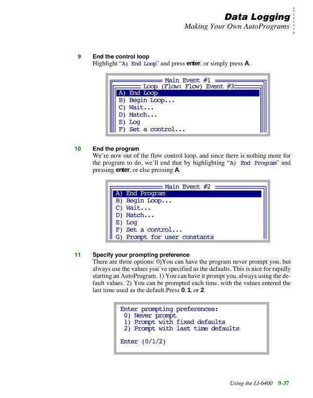
Data LoggingMaking Your Own AutoPrograms
Using the LI-6400 9-37
9 End the control loopHighlight ÒA) End LoopÓ and press enter, or simply press A.
10 End the programWeÕre now out of the flow control loop, and since there is nothing more forthe program to do, weÕll end that by highlighting ÒA) End ProgramÓ andpressing enter, or else pressing A.
11 Specify your prompting preferenceThere are three options: 0)You can have the program never prompt you, butalways use the values youÕve specified as the defaults. This is nice for rapidlystarting an AutoProgram. 1) You can have it prompt you, always using the de-fault values. 2) You can be prompted each time, with the values entered thelast time used as the default.Press 0, 1, or 2.
Main Event #1
B) Begin Loop...
D) Match...E) Log
C) Wait...
F) Set a control...
A) End LoopLoop (Flow: Flow) Event #3
Main Event #2
B) Begin Loop...
D) Match...E) Log
C) Wait...
F) Set a control...
A) End Program
G) Prompt for user constants
Enter prompting preferences: 0) Never prompt 1) Prompt with fixed defaults 2) Prompt with last time defaults
Enter (0/1/2)

Data LoggingMaking Your Own AutoPrograms
9-38 Using the LI-6400
9
12 Store the AutoProgramYou are given the opportunity to store the AutoProgram.
If you press Y, the Standard File Dialog is accessed for storing the file. Thedefault name of the file will be the sequence of selections you made, but youcan change it to something meaningful. In this case, the default name will beBaCaEAA, and the default directory will be /User/Configs/AutoPrograms. Renamingit to Humidity Curve would be a good choice. The program is then exited. If youwish to view or edit the AutoProgram that you have created, you can do so byaccessing the Filer, selecting the file, and pressing E.
If you press N, to not store the file, you will be given a chance to edit the Au-toProgram you have created. When you exit the editor (Standard Editor), youcan save the file.
Example 2: A-Ci Curves at Various Light LevelsThis example builds an AutoProgram that does a family of A-Ci curves, eachone at a different light level. The program will have this structure:
Store this AutoProgram?(Y/N)
View/Edit this AutoProgram?(Y/N)
Prompt for inputsLOOP over light level
Set light levelWait fixed timeLOOP over reference CO2
Set reference CO2Wait for stabilityMatch if deltas are smallLog
END LOOPEND LOOP
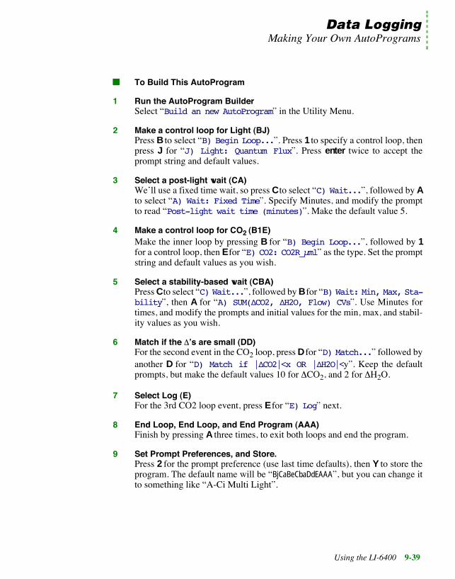
Data LoggingMaking Your Own AutoPrograms
Using the LI-6400 9-39
■■■■ To Build This AutoProgram
1 Run the AutoProgram BuilderSelect ÒBuild an new AutoProgramÓ in the Utility Menu.
2 Make a control loop for Light (BJ)Press B to select ÒB) Begin Loop...Ó. Press 1 to specify a control loop, thenpress J for ÒJ) Light: Quantum FluxÓ. Press enter twice to accept theprompt string and default values.
3 Select a post-light wait (CA)WeÕll use a fixed time wait, so press C to select ÒC) Wait...Ó, followed by Ato select ÒA) Wait: Fixed TimeÓ. Specify Minutes, and modify the promptto read ÒPost-light wait time (minutes)Ó. Make the default value 5.
4 Make a control loop for CO2 (B1E)Make the inner loop by pressing B for ÒB) Begin Loop...Ó, followed by 1for a control loop, then E for ÒE) CO2: CO2R_µmlÓ as the type. Set the promptstring and default values as you wish.
5 Select a stability-based wait (CBA)Press C to select ÒC) Wait...Ó, followed by B for ÒB) Wait: Min, Max, Sta-bilityÓ, then A for ÒA) SUM(ÆCO2, ÆH2O, Flow) CVsÓ. Use Minutes fortimes, and modify the prompts and initial values for the min, max, and stabil-ity values as you wish.
6 Match if the DÕs are small (DD)For the second event in the CO2 loop, press D for ÒD) Match...Ó followed byanother D for ÒD) Match if |ÆCO2|<x OR |ÆH2O|<yÓ. Keep the defaultprompts, but make the default values 10 for DCO2, and 2 for DH2O.
7 Select Log (E)For the 3rd CO2 loop event, press E for ÒE) LogÓ next.
8 End Loop, End Loop, and End Program (AAA)Finish by pressing A three times, to exit both loops and end the program.
9 Set Prompt Preferences, and Store.Press 2 for the prompt preference (use last time defaults), then Y to store theprogram. The default name will be ÒBjCaBeCbaDdEAAAÓ, but you can change itto something like ÒA-Ci Multi LightÓ.

Data LoggingMaking Your Own AutoPrograms
9-40 Using the LI-6400
9
The AutoProgram Builder ReferenceThe major options of the AutoProgram Builder are shown in Figure 9-21.
A) End ProgramThis item is labelled ÒA) End LoopÓ when selecting items within a controlloop. When selected from within a control loop, it ends the loop. When se-lected outside of a control loop, it marks the end of the AutoProgram.
B) Begin LoopÉThere are two types of loops: Type 1 sets a control, and the number of loopsis determined by the number of control settings. The possible controls areshown in ÒControl ListÓ in Figure 9-21, and they essentially correspond to the
A) End Program (or End Loop)B) Begin Loop...C) Wait...D) Match...E) LogF) Set a control...G) Prompt for user constantsH) Add a remarks record
A) Flow: FlowB) Flow: H2OS_mmlC) Flow: RH_S_%D) Flow: VPDE) CO2: CO2R_µmlF) CO2: CO2S_µmlG) CO2: Control VoltageH) Temp: TblockI) Temp: TleafJ) Light: Quantum FluxK) Light: Control VoltageL) Fan Speed
A) SUM(ÆCO2, ÆH2O, Flow) CvsB) SUM(ÆCO2, ÆH2O) CVsC) ÆCO2 CV onlyD) ÆH2O CV only
Action List
Control List
Stability Options List
Figure 9-21. AutoProgram BuilderÕs major options. The Type 1 Loop uses multiple control values, while theÒSet a controlÉÓ event uses one control value. The Type 2 Loop sets no control values - it is a fixed count loop.
A) Wait: Fixed TimeB) Wait: Min,Max,StabilityC) Wait, with Logging at intervals
Wait Options List
A) Match alwaysB) Match if |ÆCO2| < xC) Match if |ÆH2O| < yD) Match if |ÆCO2|<x OR |ÆH2O|<y
Match Options List
Type 1

Data LoggingMaking Your Own AutoPrograms
Using the LI-6400 9-41
controls found in the level 2 function keys of New Measurements mode.(Note: if you specify a type 1 loop, but then escape out of selecting the con-trol to be set, the loop becomes type 2.) A Type 2 loop does not set any controlautomatically, but simply loops a user-specified number of times.
Once the prompting sequence and default values are established, you selectitems for ÒinsideÓ the control loop.
Note that you can have nested loops, since ÒB) Begin LoopÉÓ is one of thein-loop possibilities. To terminate a loop, select ÒA) End LoopÓ.
C) WaitÉThere are three wait options:
A) Wait: Fixed TimeB) Wait: Min,Max,StabilityC) Wait, with Logging at intervals
During these waits, the instrument will appear to be in New Measurementsmode, allowing you to monitor channels, view real time graphics, etc.
A) Wait: Fixed Time: The A option will generate a prompt for the wait time(it can be in minutes or seconds), and a prompt for the default value to beused.
Main Event #3
A) End LoopB) Control Loop...
LOOP (Flow: Flow #1) Event #1
D) Match...E) LogF) Set a control...
C) Wait...
This loop is the 3rd event in the Auto-Program
The loop sets fixed flow control.
WeÕre picking the 1st item in the flow control loop. (This will be the first thing to happen after the flow rate is set to the next value.)
Figure 9-22. Picking items within a loop. A Type 1 loop sets the control to a newvalue automatically; you have to select everything else that you wish to have hap-pen after that, however.

Data LoggingMaking Your Own AutoPrograms
9-42 Using the LI-6400
9
B) Wait: Min, Max, Stability: The B option generates a number of prompts:You are asked to select the stability criterion:
A) SUM(ÆCO2, ÆH2O, Flow) CvsB) SUM(ÆCO2, ÆH2O) CVsC) ÆCO2 CV onlyD) ÆH2O CV only
The min and max wait times can be specified in minutes or seconds, and thereis a prompt for each, and a default value for each. Finally, there is a promptand default value to be established for the critical stability value (based on thestability choice A, B, C, or D that you made).
C) Wait, with Logging at intervals: The C option is similar to the fixed timewait, except that logging will occur automatically at regular intervals duringthis wait. The total wait duration is always specified in minutes, and the log-ging interval is specified in seconds. Prompts and default values for both areestablished.
The C option represents a short-cut to doing a Type 2 Loop that contains afixed time wait and a log. If you wish to do other events, such as matchingbefore each log, then you should specify a Type 2 Loop, rather than using thiswait option.
D) MatchÉThere are some options for matching:
A) Match alwaysB) Match if |ÆCO2| < xC) Match if |ÆH2O| < yD) Match if |ÆCO2|<x OR |ÆH2O|<y
Matching can happen always or conditionally, based on the DCO2 and/or theDH2O value. Options B, C, and D will cause prompts and default values to beestablished.
E) LogThis selection will cause data to be logged. It requires no extra information.
F) Set a controlÉThis selection is for setting a control once, as opposed to looping over severalvalues for the control. You select the control from the list shown inFigure 9-21 on page 9-40. For example, if you were building an light curveAutoProgram, and wanted to set the CO2 controller for controlling on sample

Data LoggingMaking Your Own AutoPrograms
Using the LI-6400 9-43
concentration, and the temperature controller for controlling on leaf temper-ature prior to looping over light values, you would use the ÒSet a controlÉÓoption for the CO2 and again for temperature, but then use the ÒControlLoopÓ option for setting the light values.
G) Prompt for user constantsThis will do the same thing as pressing F5 level 3 (User Consts) in New Mea-surements mode: any user constants that have been defined will be promptedfor. (Note: This suspends operation until the user responds.)
H) Add a remarks recordThis option does the same thing as pressing F4 level 1 (Log Remark) in NewMeasurements mode: it adds a remark record to the data file. (Note: This sus-pends operation until the user responds.)

Data LoggingMaking Your Own AutoPrograms
9-44 Using the LI-6400
9

Part III
Working With Files


Using the LI-6400 10-1
10The LPL File System
Managing your data storage space
FILES, DIRECTORIES, AND DISKS 10-2What Are Files? 10-3What Are Directories? 10-3What Are Disks? 10-3
DEFRAGMENTATION 10-5The Hidden Disk 10-6
THE FILER 10-6Accessing the Filer 10-6The Function Keys 10-7
FILERÕS DIRECTORY OPERATIONS 10-9Viewing & Selecting 10-10Creating 10-10Removing 10-10
FILERÕS FILE OPERATIONS 10-11Viewing File Header Information 10-11Viewing a Subset of Files 10-12Viewing and Editing a FileÕs Contents 10-13Tagging One File 10-13Tagging Groups of Files 10-14Removing Files 10-15Copying and Moving Files 10-15Duplicating Files 10-16Renaming Files 10-16Printing Files 10-16Executing Programs 10-17
FILERÕS DISK OPERATIONS 10-18Space Available 10-18
Defragmenting Disks 10-18Formatting Disks 10-19Using the Hidden Disk 10-19
TROUBLESHOOTING 10-21Out of Disk Space 10-21Out of Disk Space on _Temp_$$$_Temp_ 10-21

The LPL File System
10-2 Using the LI-6400
10This chapter describes the LI-6400Õs file system, and a very useful tool for itsmanagement: the Filer.
Files, Directories, and DisksThe LI-6400Õs file system contains the programming that makes the instru-ment work, as well as the data files that result from that work. To efficientlymanage all of this information, the storage space is partitioned into groupingsof disks, directories, and files. Physically, the files reside on the memoryboard (Figure 10-1).
Figure 10-1. The memory board is located on the digital board in the LI-6400,which is the upper full-sized board in the console.
DigitalBoard
MemoryBoard

The LPL File SystemFiles, Directories, and Disks
Using the LI-6400 10-3
What Are Files?Files on the LI-6400 are just like files on your computer: each is a collectionof data that has a name and a time stamp (when it was last modified), amongother attributes. You can copy, delete, view, edit, and otherwise manage thesefiles just as you would on a computer. Some of the files on the LI-6400 areprograms to control the LI-6400, while other files are your own creation, con-taining data youÕve collected.
Naming ConventionFile names on the LI-6400 can be as long as youÕd care to make them, and canconsist of any combination of numbers, letters, spaces, and punctuation, ex-cept the following five characters:
/ \ * ? ;
Upper and lower case does not matter for letters, so the following are equiv-alent names:
MyDatamydataMYDATA
Dots carry no significance in the LI-6400Õs file system, so names like
WheatData.plot2.aci.joe
are acceptable.
What Are Directories?Directories provide a mechanism for grouping files logically, and can containthe header information (name, date, etc.) for any number of files or other di-rectories. Directories have the same naming convention as files. In fact, direc-tories are simply a special kind of file.
What Are Disks?Disks contain directories and files. In spite of the name, they are not remov-able, like a floppy disk, and they have no moving parts, like a hard disk. Theydo have a fixed size, and follow the same naming conventions as directoriesand files.
To identify a particular file in the LI-6400Õs file system, use itÕs name, thenames of all the parent directories that contain it, and the name of the disk onwhich it is found. For example,

The LPL File SystemFiles, Directories, and Disks
10-4 Using the LI-6400
10
/User/Configs/AutoProgs/AutoLog
specifies a file named AutoLog, that is located in a directory named AutoProgs,that is in turn found in a directory named Configs, that is in the disk named User.Note that a slash (/) is used do separate directory and file names in the speci-fier. A slash in either direction will work, so the following are equivalent:
/Sys/Open/Open\Sys/Open\Open
The Root DirectoryIt is helpful to think of the entire file system as a tree of directories branchingfrom a single root. The directories that branch immediately from the root arethe disks, and subsequent directories (Figure 10-2).
Disks are like directories in terms of naming a file, but they differ from direc-tories in that the user cannot create or destroy them. The system provides afixed number of disks for you to work with.
/ The Root
Sys User
Open Lib Utility ConfigsMyData
Disks
Zero Gain AutoProgs
Files
Directories
Figure 10-2. Illustration of disks, directories, and files as structured in the LI-6400Õs file system.

The LPL File SystemDefragmentation
Using the LI-6400 10-5
DefragmentationFlash memory has the advantage of being very stable and safe, even when nopower is applied to it. The disadvantage is that it cannot be overwritten (re-used) in small pieces. This has serious implications for a file system. Everytime something is written to disk (flash memory), it must be written to a new(unused) location. This can lead to some surprises:
For example, consider the following example. You collect a number of datafiles, and find that the disk is 80% full. In an effort to make room, you deletesome no-longer-needed files, and find that the disk is now 81% full. Whathappened? The reason that the space used by the files has not been reclaimedis that it canÕt be re-used until all of it is erased. Deleting files simply markedthose files as unused, but the directory information was updated, and rewrit-ing the directory used up some new disk space.
Eventually, of course, the disk will be come full, and something needs to bedone. The normal remedy for a full disk is to defragment it. During this pro-cess (which is not automatic - you must initiate it), the contents of the disk arecopied to another disk, but only the portions that are still necessary(Figure 10-3). Deleted files, for example, are not copied.
File
1
File
2
File
3a
Dir
File
3b
Unused
Dir
Dir
Used
ÒDeletedÓ ÒDeletedÓ
File
4
File
1
File
2
File
3
Dir
UnusedUsed
a)
b)
Figure 10-3. Illustration of defragmentation. a) Before defragmentation, there are 3 files and 1 directory, alongwith a deleted file and old directory information. b) After defragmentation, the deleted files and directories aregone, and their space is reclaimed. Also, fragmented files (such as File3) are consolidated.

The LPL File SystemThe Filer
10-6 Using the LI-6400
10
The Hidden DiskFor defragmentation to work, there needs to be some destination memory forthe files to be copied to. This is achieved in the LI-6400 by keeping one of theflash disks hidden. Normally, only the /Sys and the /User disks are on-line, andthe third one is off-line. When you defragment the /User disk, for example, allthe files get copied to the hidden disk, then the hidden disk is named /User andbrought on-line, while the previous /User is formatted and taken off-line to beused for the next defragment.
If you need extra storage space, you can bring the hidden disk on-line for yourown use. As long as all disks are on-line, however, none of them can be de-fragmented.
The FilerThe FILER is a general purpose tool for managing files, directories, and diskson the LI-6400 file system. Some of the functions that you can perform withthe FILER include copying, deleting, renaming, and viewing files, as well asdisk operations such as formatting and defragmenting disks.
Accessing the FilerThere are a couple of ways to get to the Filer:
From OPENFrom the OPEN main screen, press the Utility Menu function key (f5). Select"Access the FILER", and press enter. The Filer screen appears.
From Power ONPower ON and press escape, to get to the LPL copyright screen. Then press F.
The main Filer screen shows directory statistics, a list of files, and functionkey labels (Figure 10-4). To exit the Filer, press escape while viewing thisscreen.

The LPL File SystemThe Filer
Using the LI-6400 10-7
The Function KeysTo navigate through the FilerÕs function keys, press labels until the desiredkey appears. To execute a particular task, press the corresponding functionkey, or else type the letter associated with that key. This shortcut key is al-ways the capitalized key in the function keyÕs label. (Note: This is only truefor the Filer, and is not generally true for other screens in the LI-6400).
Figure 10-4. The FilerÕs main screen
/UserFilter=Total: 34Bytes: 71962Tagged: 0Bytes: 0
A-Ci Iris leafA-Ci Test 4DataData (Jason)MixerTestResults
+ Dir Filter Sort Tag purGe
A-Ci bad
¬ ®
Use the cursor control keys to move the highlight bar.
Press ¬ or ® to view file time stamp and size.
Current Directory
The file listWhich files to display. Ò*Ó or ÒÓ for all.
Press labels for more keys, or use the short cut keys.
Table 10-1. The FilerÕs main function key labels and short cuts.
Label Short Cut
Description
Dir D Select a directory. See Table 10-4.
Filter F Change the filter for displayed files. The default fil-ter is Ò*Ó, which selects all files.
Sort S Sort the displayed list of files. See Table 10-2.
Tag T Tag one or more files in the list. See Table 10-6.
purGe G Purge all tagged files in the file list.
Copy C Copy tagged files to a another directory.
Move M Same as Copy, except the original is purged.

The LPL File SystemThe Filer
10-8 Using the LI-6400
10
dUplct U Duplicate all tagged files. The new files will haveÒcopyÓ appended to their name.
Rename R Rename the highlighted file.
Print P Print all tagged files.
View V View the highlighted file.
Edit E Edit the highlighted file.
grapH H Run GraphIt for the highlighted file.
Working W Set the current directory to be the default once theFiler is exited.
re-scAn A Re-build the list of directories, and the list of files.
disK K Access the disk keys. See Table 10-3.
eXecute X Run the highlighted file (if itÕs an LPL program).
Table 10-2. Sort key labels.
Label Short Cut
Description
by Name N Sorts files by the file name
by Date D Sorts files by the date and time
by Size S Sorts files by the file size
by Tag T Sorts files by the file tag status (selected, unse-lected, or old-selected).
Quit Q escape
Return to the main level of function keys(Table 10-1).
Table 10-3. Disk key labels.
Label Short Cut
Description
Space S Find out how much space is available on a select-ed disk.
Table 10-1. (Continued)The FilerÕs main function key labels and short cuts.
Label Short Cut
Description

The LPL File SystemFilerÕs Directory Operations
Using the LI-6400 10-9
FilerÕs Directory OperationsDirectory operations are found in to the ÒSelect DirectoryÓ screen, accessedby pressing D (or the Dir function key).
Format F Format a selected disk. This removes all datafrom it.
NewDska
HideDskN H
Bring the hidden disk on-line, or take a diskoff-line. There must be a hidden disk in order todefragment.
Defrag D Defragment a selected disk.
Quit Q escape
Return to the main level of keys (Table 10-1).
a.The key label that appears here depends on whether there is a diskoff-line or not.
Table 10-3. Disk key labels.
Label Short Cut
Description
Table 10-4. The Directory function key labels
Label Short Cut
Description
Add A Add a new directory
"/User""/User/6400 Data""/User/Configs""/User/Configs/AutoProgs""/User/Configs/AutoProgs/Defaults"
"/"Select new path or directory
+ Print Find Refind CANCEL SELECT
+ Add Purge Rename CANCEL SELECT
Figure 10-5. The ÒSelect DirectoryÓ screen is accessed by pressing D (or the Dirfunction key) from the main menu. The function keys are described in Table 10-4.

The LPL File SystemFilerÕs Directory Operations
10-10 Using the LI-6400
10
Viewing & SelectingThe ÒSelect DirectoryÓ routine shows all directories on all disks in a menu.To select a particular one, highlight it, and press enter.
CreatingUse the Add function key (or press A) in ÒDirectory SelectÓ.
RemovingUse the Purge function key (or press P) in ÒDirectory SelectÓ. A directory thatis not empty (has files or other directories) can be purged, but you will bewarned first, and will have a chance to cancel the operation.
Purge P Purge the highlighted directory. If the directory isnot empty, you will be notified and asked if youreally want to purge it.
Rename R Rename the highlighted directory.
CANCEL escape Exit the directory selection screen, and donÕtchange directories.
SELECT enter Change to the highlighted directory, and exit thechange screen.
Print Print the directory list to the Comm Port
Find Enter a target, and search for the next occurrence
ReFind Search for the next occurrence of the current target
Table 10-4. The Directory function key labels
Label Short Cut
Description
NOTE: You cannot add directories to the root (that is,you cannot add a disk). You can, however, bring the hid-den disk on-line, if it is not already. See Using the Hid-den Disk on page 10-19
NOTE: You cannot remove disks. Thus, /SYS and /USERcan't be removed. You can, however, take a disk off-line.See Using the Hidden Disk on page 10-19

The LPL File SystemFilerÕs File Operations
Using the LI-6400 10-11
FilerÕs File Operations
Viewing File Header InformationThe main FILER screen displays small left and right arrows (Figure 10-4 onpage 10-7), which indicate that additional file information can be viewed bypressing the ¬ or ® arrow keys. Pressing ¬ or ® toggles the file list to showthe time or date of last modification, or the file size, in bytes.
/UserFilter=Total: 34Bytes: 71962Tagged: 0Bytes: 0
A-Ci Iris leafA-Ci Test 4DataData (Jason)MixerTestResults
+ Dir Filter Sort Tag purGe
A-Ci bad
¬ ®
3146325689258773980
210
/UserFilter=Total: 34Bytes: 71962Tagged: 0Bytes: 0
A-Ci Iris leafA-Ci Test 4DataData (Jason)MixerTestResults
+ Dir Filter Sort Tag purGe
A-Ci bad
¬ ®
11 Aug 9710 Aug 9707 Nov 9731 Jul 9731 Jul 97
11 Aug 97
/UserFilter=Total: 34Bytes: 71962Tagged: 0Bytes: 0
A-Ci Iris leafA-Ci Test 4DataData (Jason)MixerTestResults
+ Dir Filter Sort Tag purGe
A-Ci bad
¬ ®
14:54:0612:10:3509:48:2111:10:1013:08:50
14:44:53
Figure 10-6. Use the ¬ and ® keys to display file sizes, modificationdates, and modification times.

The LPL File SystemFilerÕs File Operations
10-12 Using the LI-6400
10
Viewing a Subset of FilesThe file list can include all files in a directory, or a subset of them This is con-trolled by the Filter setting (Figure 10-7)
To show a particular set of files, specify a mask using the Filer key (or justpress F). You are prompted to enter the new Filter string. Examples are givenin Table 10-5.
Table 10-5. Examples of Filters, and the files they would include and exclude.
Filter Includes Files Excludes Files
* (all) (none)
*123* 123.dat Data123 123
12.3
Data.? data.1 data.x
data data.123
*.??? junk.dat this is long.123
junk.12 junk.1234
/UserFilter=*data*Total: 3Bytes: 962Tagged: 0Bytes: 0
More Datathis data is ok
+ Dir Filter Sort Tag purGe
Data
¬ ®
Figure 10-7. The Filter determines which files are shown. A blank, or *,will show all files. The characters* or ? are wild cards.

The LPL File SystemFilerÕs File Operations
Using the LI-6400 10-13
Viewing and Editing a FileÕs ContentsTo view the contents of a file, highlight it and press View (or V). Refer toStandard Menu on page 5-2 for details. To edit a file, press Edit (or E) in-stead. Refer to Standard Edit on page 5-13 for details on using this editor.Whether viewing or editing, the display will look the same (Figure 10-8) untilyou press the labels key; different functions keys are defined for viewing andediting.
There is no limit to how large a file can be viewed, but there is a limit on howlarge a file can be edited. That limit is 64K bytes or the largest contiguousblock of memory that is available, whichever is smaller.
Tagging One FileMany of the FILER commands require that files or directories be selected(ÒtaggedÓ) before the command can be executed. These operations includepurging, copying and printing files.
Press the Space or Enter keys to tag the highlighted file, or press Tag, fol-lowed by tag One. A tag symbol appears next to the file name (Figure 5-3),and the highlight moves to the next file. When a file is tagged, press theSpace or Enter keys again to remove the tag. Additional function keys asso-ciated with the Tag function (below) are accessed by pressing Tag.
_ maxWaitTime 300 pmWait 10
:PTR user[]{ :PTR { co2Vals Ò\nDesired Ca values (µm :PTR { minWaitTime ÒMinimum wait time (
237A-CiCurve=
Cursor Offset in file (bytes)
Position Indicator (left edge = start of file, right edge = end of file)
Figure 10-8. Viewing or editing a file looks the same. Viewing will not allow you tomake changes, however.

The LPL File SystemFilerÕs File Operations
10-14 Using the LI-6400
10
Tagging Groups of FilesTo tag a group of files, press T (or the Tag function key), and use the tag func-tion keys (Table 10-6).
Figure 10-9. The FilerÕs main screen, showing two tagged files.
/UserFilter=Total: 34Bytes: 71962Tagged: 2Bytes: 10972
A-Ci Iris leafA-Ci Test 4DataData (Jason)MixerTestResults
+ Dir Filter Sort Tag purGe
A-Ci bad
¬ ®
▲▲
Tagged files are marked.
Number of tagged files, and size in bytes
Table 10-6. Tag function keys
Label Short Cut
Description
Tag all T Tag all files in the current directory list.
Clr all C Remove all tags from files in the current directorylist.
Retag R After you have performed certain functions (e.g.,copying files), the tag marker will change to a - (hy-phen) to indicate that the command was executed onthe tagged files. Press Retag to tag these files againfor further operations.
Invert I Tag all files that are currently not tagged, and re-move the tag from those files that are tagged.
tag One O Tag the currently highlighted file. (A faster way totag one file is to press enter or space from FilerÕsmain screen.)

The LPL File SystemFilerÕs File Operations
Using the LI-6400 10-15
Removing FilesTo remove files, you must first tag them (above), and then press the purGekey (or G). Press Y (Yes) at the prompt to delete the file(s). Purged files areplaced in the Trash directory on the parent disk. The disk must be defragment-ed to actually remove old files and free up disk space. See DefragmentingDisks on page 10-18.
Copying and Moving FilesThe only difference between moving and copying is that the original ispurged after moving.
■■■■ To move or copy files from one location to another:
1 Tag the file(s) to be copiedTag by pressing enter or space, or by the Tag function keys.
2 Press M for Move, or C for CopyOr use the function keys.
3 Select the destinationA menu of destinations is presented. Highlight the desired destination direc-tory, and press enter. Or press escape, if youÕve changed your mind.
4 Select the overwrite optionYour choices are shown in Figure 10-10. Press Y (Yes) to overwrite existingfiles with the same name, N (No) to prevent files from being overwritten, orA (Ask) to bring up another prompt (Y/N) each time such a file is found.
File Copy
Overwrite duplicate files ?(Yes, No, Ask when it happens)
(Y/N/A)
Figure 10-10. When moving or copying, you are given options on what todo if there is a duplicate file in the destination directory.
Or Move

The LPL File SystemFilerÕs File Operations
10-16 Using the LI-6400
10
Duplicating FilesThe purpose of duplicating files is to allow copying to the same directory. Alltagged files generate a duplicate, with ÒcopyÓ appended to their name. To du-plicate tagged file(s), press U or dUplct.
Renaming FilesTo rename a file
1 Highlight the file to be renamed
2 Press Rename (or R)You are then prompted for a new name (Figure 10-11).
3 Press escape or enter.enter renames the file, escape aborts.
Printing FilesDownloading files is discussed in Chapter 11. One method of downloadingthem is to tag them in the Filer, and press P (or Print). The print program thatthen runs will prompt you for the following information:
¥ Print headers? (Y/N)If you press Y, a banner will be output before each file. The banner will in-clude the file name, modification date, and current date.
/UserFilter=Total: 34Bytes: 71962Tagged: 0Bytes: 0
A-Ci badA-Ci Iris leafA-Ci Test 4DataData (Jason)MixerTestResults
¬ ®
New name: A-Ci bad_
Figure 10-11. Renaming the highlighted file. Standard Line Edit is used (page 5-5). The editing functionkeys are not shown, since the edit line obscures the function key labels. The function keys are still effective,however, and their labels be viewed by pressing labels.
Enter or edit the new name here

The LPL File SystemFilerÕs File Operations
Using the LI-6400 10-17
¥ Append FormFeeds? (Y/N)If you press Y, each file will be followed by a form feed (decimal 12), whichwill cause most printers to eject the page. This allows each file to begin on anew page, if you are printing multiple files to a printer.
¥ Select ConversionYou will be prompted for a conversion type (Figure 10-12).
The file(s) are then sent to the Comm Port.
Executing ProgramsLPL programs can be run from the FILER by highlighting the file containingthe program and selecting eXecute (or X). After the program is executed, youwill return to the FILER. As an example, you can set the communications pa-rameters from the FILER by executing the /Sys/Utility/Setcomm program file.
Utility programs in the directory /Sys/Utilities are described in /Sys/UtilityPrograms on page 21-10.
Print headers? (Y/N)NAppend FormFeeds? (Y/N)NConversions N) None S) to Space delimited C) to Comma delimited T) to Tab delimited
Figure 10-12. The print program has some delimiter conversion options: PressingN prints the file as is, S prints it as space delimited, C as comma delimited, and T

The LPL File SystemFilerÕs Disk Operations
10-18 Using the LI-6400
10
FilerÕs Disk OperationsThe function keys for the disk operations are accessed by pressing the disKfunction key (or K).
Space AvailableIt is a good practice to defragment the disk before the available space reacheszero. The /User disk is automatically checked when OPEN first runs, and thepercent space available on this disk is displayed in OPENÕs main screen.
■■■■ To find the space available on a disk:
1 In the FILER, press the disK function key (or K). The Disk function keys appear.
2 Press Space (or S).A list of the disks appears.
3 Select a disk and press Enter. The space used and the space available is displayed (Figure 10-13). Press anykey to return to the FILER.
Defragmenting DisksIt is periodically necessary to defragment the disks to reclaim space occupiedby inactive files. During defragmentation, all active files are copied onto theHidden disk (see Using the Hidden Disk on page 10-19). The original diskis then reformatted and all inactive files are purged. The active files are thencopied back to the original disk.
The time required to defragment a disk depends upon how much disk spaceis to be reclaimed, and the number of inactive files that must be purged. Asan example, a disk containing one large file takes only about half a minute todefragment, whereas a disk that contains a lot of smaller files and directoriescan take several minutes.
Figure 10-13. The available space message. The total space onthe disk is the sum of these two numbers.
Used = 33233 bytesAvail = 491055 bytes
Space on /user
Press Any Key

The LPL File SystemFilerÕs Disk Operations
Using the LI-6400 10-19
■■■■ To defragment a disk:
1 Display the Disk function key labelsPress the disK function key (or K).
2 Select a diskPress the Defrag function key (or D) to display a list of the disks.Highlight the desired disk, and press enter.
3 Read the NoticeYouÕll be given a notice that it might take a couple of minutes. Press Proceedor Cancel.
Formatting DisksFormatting will erase all files on a disk. Formatting differs from defragment-ing, in that defragmenting does not erase active files. Do not format the /SYSdisk, as it contains system operating files that affect the operation of theLI-6400. These files can be reloaded from the system floppy disk.
■■■■ To format a disk:
1 Access the disk keysIn the FILER, press the Disk function key (or K).
2 Select a diskHighlight the disk to be formatted, and press enter.
3 Read the warningIf itÕs ok to proceed, and loose everything on the disk, press Proceed. Other-wise, press Cancel.
Using the Hidden DiskThe hidden data disk is used during defragmentation to temporarily store ac-tive files from the disk being defragmented. The hidden disk can be used fortemporary data storage if the other disks become full. Note, however, that nodisks can be defragmented if the hidden disk is in use.
NOTE: If you format the /USER disk, youÕll need torun the ÒReinstall Config FilesÓ program, found in theReset Menu (in the Config Menu).

The LPL File SystemFilerÕs Disk Operations
10-20 Using the LI-6400
10
■■■■ To use the hidden disk:
1 Access the disk keysIn the FILER, press the Disk function key (or K).
2 Press the NewDsk function key (or N).If there is none, then the hidden disk is already on-line.
3 Enter the new diskÕs nameYou will be prompted for a name for the new disk. Enter something (such astemp), and press enter. The FILER then rescans the system and displays a re-vised list of available disks.
If you are using the hidden disk, you must create a hidden disk again beforedefragmenting. Make sure that you copy all of the files that you want to savefrom the disk that is to be hidden (see Copying Files in this section). All fileson the specified disk will be erased when it is hidden.
■■■■ To hide the temporary disk:
1 Access the disk keysIn the FILER, press the Disk function key (or K).
2 Press the HideDisk function key (or H)If there is no such key, then the disk is already off-line. Highlight the entry,and press enter.
3 Select a disk to hideHighlight the entry, and press enter.
4 Read the warning. You are then prompted to continue. Press Proceed to hide the disk (and looseall data stored on it).

The LPL File SystemTroubleshooting
Using the LI-6400 10-21
Troubleshooting
Out of Disk SpaceIf a disk runs out of space, a message will appear (Figure 10-14) every timean attempt is made to write to the disk.
When this happens, remember that powering off and back on will never fixthis problem. The proper way to fix the problem is to defragment the disk(Defragmenting Disks on page 10-18). If there are files on the disk that youcan delete, do so before defragmenting. Note that deleting these files willcause the ÒOut of disk spaceÓ message to appear at least once for each file de-leted, but persevere, and press enter each time to clear the message. Defrag-menting will ultimately fix the problem.
Out of Disk Space on _Temp_$$$_Temp_(or on _Swap_$$$_Swap). When this message occurs, it means the hiddendisk is out of space. This can happen when a full disk is defragmented, andthe defragment doesnÕt recover any space. The remedy to this situation is atwo step process:
1 Bring the hidden disk on-lineThis is described in Using the Hidden Disk on page 10-19; in the Filer, pressK, then f3, and name it temp.
2 Take the temp disk back off lineFrom the Filer, press K, then f3, and select the temp disk to take off line. Tak-ing the disk off line will format it, and make it available for use with defrag-menting again.
Out of disk space on /User
Press Enter
Name of disk with the problem
Figure 10-14. This message will appear every time an attempt is made towrite to a full disk.

The LPL File SystemTroubleshooting
10-22 Using the LI-6400
10

Using the LI-6400 11-1
11Downloading Files
Retrieving your data
CONNECTING THE LI-6400 TO A COMPUTER 11-3
FILE EXCHANGE MODE 11-4
USING WINFX 11-4Installation 11-4Example 11-4Program Comments 11-7
USING FX FOR DOS 11-8Installation 11-8Example 11-8Program Comments 11-10
USING FX ON MACINTOSH 11-10Installation 11-10Example 11-11Program Comments 11-12
USING EW 11-12Installation 11-12Examples 11-13EWÕs Switches 11-17
ODDS AND ENDS 11-21Text vs. Binary Files 11-21File Name Considerations 11-21Non-standard Serial Port Configuration (DOS only) 11-23
USING A DATA CAPTURE PROGRAM 11-23Setting the Communication Parameters 11-231000-90 COMM Software for DOS 11-241000-91 Comm for Macintosh¨ 11-26

Downloading Files
11-2 Using the LI-6400
11Eventually youÕll want to move files from the LI-6400 to your computer, oreven load files back onto the LI-6400. When you do, you have three options:
1 Use FX softwareFX is available for DOS or Windows or Macintosh. These programs arefound on the LI-6400 CD (ÒUsing the LI-6400Ó, Edition 2), and can also bedownloaded from CORE support in LI-CORÕs web site (www.licor.com).These programs allow for very easy file transfer in either direction, all con-trolled from the computer. In addition, one can do other file system opera-tions, such as remove files or directories, defragment, etc.
2 Use EWEW is essentially FX, but with a command line interface. This program canbe found on the CD and web site, and is also used for software installation.
3 Use the FilerRun a generic communications program on your computer (such as Hyper-Terminal), and specify a destination file. On the LI-6400, use the Filer to tagand send (via print) all files you want downloaded. LI-COR has data captureprograms for DOS (part number 1000-90) and Macintosh (1000-91).
Options 1 and 2 are the best. File names and structures are preserved, data iserror checked, and both are quite painless to use. Also, you neednÕt worryabout configuring the LI-6400Õs comm port when using FX or EW - itÕs au-tomatic.
Option 3 works, but is sort of a last resort. If you want to preserve theLI-6400Õs file structure on your computer (that is, each LI-6400 file retainsitÕs original name, rather than being all lumped together in a single file onyour computer), itÕs more work, because you download files one at a time,and name the destination files one at a time. To put files back onto the LI-6400, you must run a capture program on the LI-6400 (thereÕs one called “Sim-ple Terminal” in /Sys/Utilities - see page 21-19). Again, though, itÕs a one at a timeprocess. Another possible problem with option 3 is that no error checking isdone on the data transfer: whatÕs received may or may not be what is sent. Ifyou work at 9600 baud or less, you should be OK, however.

Downloading FilesConnecting the LI-6400 to a Computer
Using the LI-6400 11-3
Connecting the LI-6400 to a ComputerThere are two flavors of RS-232 devices in the world: Data CommunicationsEquipment (DCE) and Data Terminal Equipment (DTE). In terms of 25 pinconnector pin assignments, DCE devices send data on pin 3, and receive onpin 2. DTE devices do the opposite. A null modem cable interchanges pins 2and 3 (and 6 with 20) so that DCE can talk to DCE, and DTE (or 9-pin AT)can talk to DTE (or 9-pin AT). The 1000-09 cable that comes with theLI-6400 is a null modem cable.
Your computer is probably a DTE (or 9-pin AT) device, although there is noguarantee of this. Since the LI-6400 is a 9-pin AT device, youÕll need a nullmodem cable to communicate with your computer.
Many computers (and most laptops) use a 9-pin AT connector for theRS-232C port, in which case an adapter cable (such as the 1800-04 fromLI-COR), or a 25-pin to 9-pin adapter is required.
The LI-6400 is configured with a male 9-pin AT connector on the console.Plug the 9-pin end of the 1000-09 cable into the console, and plug the 25-pinfemale connector into the serial port on your PC. If you are connecting to a9-pin AT serial port on your PC, connect the 1800-04 cable to the 1000-09(Figure 11-1).
Figure 11-1. Typical cable connections.
9 pin AT
LI-6400
9 pin AT
LI-6400
9 pin AT
LI-6400
9 pin AT
LI-6400
25 pin DTE
Computer
9 pin AT
Computer
25 pin DCE
Modem
Modem port
Macintosh
1000-09
1800-04
1800-04
1000-09
1000-09Hayes Modem
cable

Downloading FilesFile Exchange Mode
11-4 Using the LI-6400
11
File Exchange ModeTo use EW or any of the FX programs, the LI-6400 must be in File ExchangeMode. There are three methods of accomplishing this:
1 From the LPL Copyright ScreenPress X.
2 While OPEN is runningAccess the Utility Menu, and select ÒFile Exchange ModeÓ.
3 From power off(Does not work for LPL versions before 2.0.) On your computer, run FX ortype the desired EW command (described below), then when FX or EW iswaiting for the LI-6400, power it on. The LI-6400 will automatically enterFile Exchange Mode. (Note: With WinFX, this technique is tricky, becausethere is only a few second window in which the program tries to establishcommunications; if it canÕt, it stops trying.)
Using WinFXWinFX (introduced in May 1999) is the Windows version of FX.
InstallationAn installer program is located on the ÒUsing the LI-6400Ó CD (Edition 2). Itcan also be downloaded from CORE support in www.licor.com.
The installation program will create a directory named WinFX in the ProgramFiles directory on your hard disk, and put a WinFX entry into WindowsStart®Programs menu.
Example
■■■■ To transfer files using WinFX
1 Connect the cablesMake sure that the cables are connected using one of the configurationsshown in Figure 11-1 on page 11-3.
2 Run WinFXThe installer should have put a WinFX entry in WindowÕs Start->Programsmenu. Use that, or find the application itself and double click it.

Downloading FilesUsing WinFX
Using the LI-6400 11-5
3 Specify the comm portWhen WinFX runs,youÕll be asked to specifythe comm port to whichthe LI-6400 is connected(Figure 11-2).
If you are doing the pow-er on / automatic entryinto File Exchange mode(Option 3 under File Exchange Mode on page 11-4), then power the LI-6400on as you click Select in Figure 11-2.
4 WinFXÕs Tree ViewsWinFX provides a graphical view of the contents of the LI-6400, and the Lo-cal System. You can expand or contract the view by clicking on the node box-es that have a + or - in them (Figure 11-3).
Figure 11-2. Selecting the comm port in WinFX
Figure 11-3. WinFXÕs tree views.
Click here to expand the tree

Downloading FilesUsing WinFX
11-6 Using the LI-6400
11
5 Open the Destination DirectoryClick on the directory you wish to receive the files. In Figure 11-4, for exam-ple, weÕll be putting LI-6400 files into the MyData directory on the C drive.
6 Select the File(s) to SendOpen the source directory by clicking on it, and select the files. Click on a filename to select it. For multiple files, hold ctrl down when you click. InFigure 11-5, we are set up to send three files.
Figure 11-4. Click the destination directory to open it. Its name will appear in the activedirectory window.
The active directories are shown here
Figure 11-5. Select the file(s) you wish to copy, and send them by pressing the appropriatearrow button.
To select multiple files, hold ctrl down when you click.
Press this button to copy from the LI-6400 to the PC

Downloading FilesUsing WinFX
Using the LI-6400 11-7
7 Click the ¬ ButtonClicking the ¬ button to send the files to the PC. The copy status will beshown on WinFXÕs status bar (Figure 11-6).
Program Comments
Communications ProblemsIf communications cannot be established atthe start, an error dialog will appear, asshown to the right. This is usually the resultof using the wrong cable(s), or plugging into the wrong place on the computer.
If communications are somehow lost during file operations (cable falls off,battery goes dead, file exchange mode is terminated, etc.), the only indicationwill be the ÒNot ConnectedÓ in the status bar. In that case, you can click theConnect button to re-establish communications.
Drag and DropSingle files or directories can be copied in either direction this way, but notmultiple files (marked with a check).
Deleting FilesSelect the file or files to be deleted, then click on the Delete button for thatview.
Copying DirectoriesThis is allowed. Click on the directory to be copied, and either drag it to thedestination directory, or use the arrow button.
Figure 11-6. During a copy, the status bar indicates which file is being transferred, and itsprogress.

Downloading FilesUsing FX for DOS
11-8 Using the LI-6400
11
Making DirectoriesClick the parent directory to select it,then click the MkDir button. Enter thenew directoryÕs name in the dialog thatappears and press Enter, or click OK.
Renaming Files or DirectoriesClick the file or directory to be re-named, then click the Rename button. A dialog will appear (like the oneabove). Avoid these characters in file names:
/ \ * ; ?
They are not allowed on the LI-6400.
Using FX for DOSThe program FX.EXE was the original file transfer method before WinFX.Being a lowly DOS program, it dealt with long file names by maintaining aspecial file that mapped legal DOS names to any LI-6400 files with illegalnames that were sent to the PC (File Name Considerations on page 11-21).
In May 1999, version 4.0 was released. FX 4.0 is 32-bit friendly, and can han-dle long file names. With the advent of WinFX, there is perhaps no need forthis program, but it remains available.
InstallationAll that is needed is the file FX.EXE. It is available on the 6400 CD, and fromCORE support on www.licor.com. Copy the file to your hard disk, putting itin the directory of your choice.
Example
■■■■ To transfer files using FX.EXE
1 Connect the cablesMake sure that the cables are connected using one of the configurationsshown in Figure 11-1 on page 11-3.
2 Run FXWhile you can launch FX from Windows by double clicking it, if you need tospecify port or baud rate information, youÕll need to launch it from a DOS

Downloading FilesUsing FX for DOS
Using the LI-6400 11-9
window. Type FX at the DOS prompt, including if necessary port specifier,with the working directory set to the appropriate directory. For example
C:>fx
will use Com1, while
C:>fx -p2
will use Com2. When the message shown in Figure 11-7 appears, go on to thenext Step.
3 Enter File Exchange ModeUse one of the three methods described on page 11-4. The when this happens,the display on the PC should change to something like in Figure 11-8.
The FX/DOS display shows the PCÕs directory and files on the left, and theLI-6400Õs on the right. The double window indicates the active window, and
Figure 11-7. The message displayed while FX waits for anLI-6400 to be connected and to enter File Exchange Mode.
Figure 11-8. FX/DOS screen. The double border window indicates the active window.

Downloading FilesUsing FX on Macintosh
11-10 Using the LI-6400
11
the source for any file transfers. Pressing Tab will change the active window.Press D to change the directory of the active window. To move files, activatethe sourceÕs window, tag the files to be copied, and press C
4 Select the destination directoryPress D and navigate to the appropriate directory. If you wish to make a newdirectory, navigate to the parent directory, and press M (Mkdr).
5 Tag the files to be copiedPress tab to activate the source window, navigate to the appropriate directory,and tag the files to be copied.
6 Copy the filesPress C (Copy) to copy tagged files in the active window to the destinationdirectory. YouÕll be given the option to treat the files as text or binary. SeeText vs. Binary Files on page 11-21 for a discussion. YouÕll also be giventhe option of overwriting existing files with the same name (yes, no, or onlyif it is older).
Each file is copied, and will have the same name on the destination as it hadon the source. However, since LPL supports long file names, and DOSdoesnÕt, FX (prior to version 4.0) uses a map file to ÒpreserveÓ LPL names onthe PC. See File Name Considerations on page 11-21.
Program CommentsFX offers some flexibility over WinFX, such as being able to copy only filesthat have changed. FX does not support renaming files, however.
Using FX on MacintoshFX for Macintosh, with version 1.4, adds support for the PowerPC processor.
InstallationFX for Macintosh is available on the 6400 CD, and from CORE support inwww.licor.com. The installation program will create a directory on your harddisk named FX 1.4, in contains the application. If you have a 680x0 processor,this application is named FX 1.4. On a PowerPC, it is named FX 1.4 PowerPC.

Downloading FilesUsing FX on Macintosh
Using the LI-6400 11-11
Example
■■■■ To transfer files using FX/Macintosh
1 Connect the cablesConnect the 9-pin end of the 1000-09 cable to the LI-6400, and connect the25-pin end to a Hayes compatible modem cable for the Macintosh(Figure 11-1 on page 11-3). The Hayes cable terminates in a standard male25-pin connector which will mate directly with the 1000-09. Connect theHayes cable to the modem port on your Macintosh.
2 Launch FXDouble click the FX application icon.
3 Establish communicationsPut the LI-6400 into File Exchange Mode (page 11-4), and click on the Con-nect button. You should be able to navigate through the Macintosh file sys-tem, and the LI-6400 file system (Figure 11-9).
Figure 11-9. FX/Macintosh shows files and directories on both the LI-6400 and the Macintosh. Di-rection of file transfer is set by the arrow direction.
In version 1.3 and above, you can shift-click this button to ac-cess the entire directory structure of the LI-6400. This speeds navi-gating, since you can jump direct-ly to the directory you want.

Downloading FilesUsing EW
11-12 Using the LI-6400
11
4 Tag items to be copiedTag files (or entire directories) that you wish copied.
5 Set the direction arrowMake sure the direction arrow is aimed in the desired direction.
6 Click SendThe Send dialog allows you to specify text or binary (or autodetect), what todo with duplicate file names, among other things.
Program Comments
Disk ImagesFX/Macintosh (and EW) allow images of LI-6400 disks to be transferredfrom the LI-6400 to a file on the computer, or a previously stored disk imageto be put back onto the LI-6400. This has utility for archiving, and for recov-ering ÒlostÓ files. ThereÕs no clean way provided to extract files from a diskimage file. You can, however, open the file with a text editor, and look forthings. Most of the file will be text, interspersed with gibberish (binary direc-tory information). Unless a file is fragmented, you will find them intact.
Using EWEW is a tool for copying files and/or directories from the LI-6400 to a PC (orPC to LI-6400). It is a command line version of FX1. It is useful for makingbatch files for routine tasks such as backups.
Version 2.0, released in May 1999, is 32-bit, and supports long file names.
The data transfer is done via error-checked data packets, allowing reliabletransfer even at high baud rates. Optional switches enable or disable variousfeatures, such as updating only newer files, or suppressing subdirectory copy-ing. It is a command line program, which means you type in a line statingwhat you want to do, then EW does it.
InstallationNo special installation procedures are required to install the EW program.Just copy the file EW.EXE from the 6400-50 System Software diskette (or fromthe 6400 CD) to your hard disk.
1.In fact, the name EW comes from FX: It is Òone shortÓ of FX. (That should cureyou of reading foot notesÉ)

Downloading FilesUsing EW
Using the LI-6400 11-13
■■■■ To install EW on your hard disk
1 Make a subdirectory for itFor example, you may want to make a directory called LI6400. Navigate tothe parent directory (or root, as is the case in this example), and at the DOSprompt type the make directory command:
C:>md \LI6400
Then, change to that directory
C:>cd \LI6400
2 Copy EW.EXE to that directoryInsert the 6400-50 System Software diskette into the floppy drive (weÕll as-sume itÕs A:), and type:
C:\LI6400>copy a:\ew.exe
EW will now be located in the directory LI6400.
ExamplesThe EW program is run by typing
ew <dos> <lpl> [switches]
at a DOS prompt. <dos> is the starting DOS directory to be involved in thetransfer, and <lpl> is the starting LI-6400 directory to be involved. The op-tional switches are described below. Both <dos> and <lpl> must exist whenEW is run; but any subdirectories in either directory will be created if neces-sary.
Note that if the LPL directory contains any spaces in the name, you must en-close the entire directory name in quotes. For example,
ew c:\mydata "/user/just a test"
The quickest way to learn to use EW is by example, and we present severalhere. EWÕs switches are is presented later, on page 11-17.
All of these examples assume that
¥ EW is installed on the hard driveThis is described above.

Downloading FilesUsing EW
11-14 Using the LI-6400
11
¥ EW is in the current working directoryThat is, if you type DIR, youÕll see the file EW.EXE.
¥ The proper cables are in placeAs described in Connecting the LI-6400 to a Computer on page 11-3.
¥ The LI-6400 is in File Exchange Mode
¥ You are using Com1 on the PCIf you are using Com2, then add the switch -p2 to all ew commands in the fol-lowing examples.
¥ You are using 9600 baudIt does not matter how the LI-6400 is configured; when you enter file ex-change mode, it will set itself to 9600 baud. However, if you have a reason-ably fast computer, you will be able to work at a much higher baud rate. Youcan do this by adding a baud rate switch to each ew command. For example,to operate at 115200 baud, add -b115200.
Once all of these things are set, proceed.
Important Hint:If you ever plan on sending files BACK to the LI-6400, make sure you donÕthave EW.EXE sitting in a directory that is going to be sent. This is why in theabove example, we have EW.EXE in c:\LI6400, and all data files in subdirectory\User off of that. Otherwise, a copy of EW.EXE will wind up on your LI-6400disk. (No, the LI-6400 canÕt run it...)
■■■■ To copy data files from the LI-6400 to the PC
1 Make a destination directoryMake a subdirectory for the data. For example, if you wish to name it user,type
md data
2 Run EWTo copy all files in /user (but not any of its subdirectories) to the PC directorydata, type
ew data /user -r -n
You should see something similar to Figure 11-10 on the PCÕs screen.

Downloading FilesUsing EW
Using the LI-6400 11-15
Variation #1To do the reverse of this, and copy all files in the PC subdirectory data to /us-er, leave off the -r switch:
ew data /user -n
If there are no subdirectories in data, then you wonÕt need the -n switch, ei-ther.
Variation #2To copy selected files, rather than all files, you can specify a wild card usingthe -m switch. For example,
ew data /user -r -n -m*aci*
will copy only files in /user that have ÒaciÓ in their names.
■■■■ Backup all data files, and configuration files, on the PCThis is a useful example. If you do this after every data taking session, youÕllalways have an updated copy of the /user disk on your PC.
1 Make a subdirectory on the PCYouÕll want a destination directory. If we follow our first example, weÕll haveone named data.
EW 1.3 Copyright (c) LI_COR, inc 1995, 1996Receive modeNo subdirsEstablishing contact with the LI-6400LI-6400 must be in file exchange mode......Go..............aci.........auto light.......man light....C:\LI6400>_
File names appear as they are transferred.
The -r switch specifies LI-6400 to PC.
The -n switch suppresses subdirectories from also being transferred.
EW waits here, attempting to communicate with an LI-6400 in File Exchange Mode
Figure 11-10. PC display when EW is run. The lines following the copyright line list the options specifiedby the switches used in the command line.

Downloading FilesUsing EW
11-16 Using the LI-6400
11
2 Run EWType
ew data /user -r -u
WeÕre not using the -n switch, because we want all subdirectories, and weÕveadded the -u switch, which means Òcopy only if it isnÕt there, or is there butwith an older dateÓ.
Variation #1How to restore the data? If the LI-6400Õs /user disk has been recently format-ted, do this:
ew data /user
If, on the other hand, you have only lost a couple of files, and you want to getthem back, then use the -u switch, which will bring back the ones that aremissing
ew data /user -u
■■■■ Archive the /user diskThis method of backup has the advantage of being potentially quicker thanthe file by file method just described. The disadvantage is that the disk willexist as one binary file on your computer, so itÕs not accessible as individualfiles, unless you put it back into the instrument.
1 Defragment the /user diskThis will make the resulting binary file smaller. If youÕve recently defrag-mented, then you may not need to do this.
2 Run EWType
ew user.bin /user -r -d
This will create a binary file, named user.bin, on your hard disk, in the currentworking directory. To put this file back into the instrument (overwriting the/user disk entirely), type
ew user.bin /user -d

Downloading FilesUsing EW
Using the LI-6400 11-17
EWÕs SwitchesThe switches are summarized in Table 11-8. You can get this information onthe screen of your computer by simply typing EW with no other parameters.Switches can appear in any order or combination.
-b(baud)The default is 9600. Table 11-3 on page 11-24 lists the possible baud rates.
ew c:\mydata /user/joe -b115200 -r
will use 115200 baud rate.
Table 11-1. Switches for EW
The Switch Switch Description
-b(baud) Baud rate (default = 9600)
-p(port) Serial port to use (1, 2, 3, or 4; default = 1)
-i(irq) The interrupt vector for the comm port (only needed fornon-standard comm ports).
-r Send files from the LI-6400 to the computer (default:files go to the LI-6400)
-u Skip files that haven't changed. (Default: do all files)
-n Send only this directory (Default: does all subdirectoriesas well)
-y Send files in binary form (default is text form)
-f(name) Send this LPL program and execute it before copying
-h(name) Send this LPL program and execute it after copying
-g(name) Send this LPL program and execute it. Do no copying
-s(string) Send this string before any other action.
-m Specify files by a mask, using the wild cards ? and *.
-d Disk image. (This overrides -u. -n, -y, and -g). The firstparameter after the ew (<dos>) is the binary file name.

Downloading FilesUsing EW
11-18 Using the LI-6400
11
-p(port)Specify comm port (1, 2, 3, or 4). The default port is 1. To use com2:
ew c:\mydata /user/joe -b19200 -p2
-i(irq)Specify non-standard interrupt vector for the comm port. See Non-standardSerial Port Configuration (DOS only) on page 11-23 for examples on howto use this.
ew c:\mydata /user/joe -b19200 -p3 -i9
-rReceive (LI-6400 to PC) files. The default is sending (PC to LI-6400).
ew c:\mydata /user/joe -b115200 -r
-uRather than overwriting files with duplicate names that exist on the destina-tion, only overwrite those files that are older than the incoming file. The de-fault is to overwrite all files, regardless of date.
ew c:\mydata /user/joe -b115200 -r -u
-nDo only the files in the specified directory; if there are any subdirectoriesfound in that directory, ignore them. The default is to include all subdirecto-ries.
ew c:\li6400\special /user/configs -r -n
-yDo no end of line conversions, but rather send the files byte-for-byte. SeeText vs. Binary Files on page 11-21
-f(filename)This switch allows an LPL program that is residing on the computer to be sentto the LI-6400 and executed before any files are copied. The following exam-ple
ew data /user -b115200 -fprep.lpl
will send the file prep.lpl to the LI-6400, which will compile and run it, priorto doing the prescribed data transfer. If the file prep.lpl looked like this:
:fct main { "/user" dskpack}

Downloading FilesUsing EW
Using the LI-6400 11-19
then this program would defragment the /user disk.
-h(filename)Similar to the -f switch, except the LPL program is sent and run after thecopying is done.
ew data /user -hc:\myprog
Notice what follows the -h (or -f or -g) can include not just the file name, butthe complete specifier if this file is not in the current working directory.
-g(filename)Similar to the -f and -g switch, except NO copying is ever done. Thus, youcould type
ew . . -gc:\myprog
The -g switch does no copying, so we specify both directories as dots; what-ever we specify is ignored anyway.
-s(string)Send the specified string prior to doing anything else. This is a switch that ex-ists for the INSTALL program2, and is unlikely to be useful to anyone else.
-m(mask)To send a particular file, or a set of files, specify the name or mask with the -m switch. * and ? are wild card characters. * means any character or charac-ters, including nothing, while ? means any character in that location. For ex-ample,
ew data\ /user -n -m*grass*
would transfer any file in the /user directory (only) with ÒgrassÓ somewherein itÕs name, including grassTest, swordGrassData, or grass. The command
ew data\ /user -n -mgrass.??
on the other hand, would only send files with names like grass.12 or grass.xy. Itwould not send grass.dat or grass because those names do not have exactly twocharacters following the dot. The wild cards ? and * can be used together. Thecommand
2.The INSTALL program uses the -s to launch LPL (by sending an R), since theLI-6400 is still sitting in the boot screen after downloading LPL.
Downloading FilesUsing EW
11-20 Using the LI-6400
11
ew data\ /user -n -m*X??
would send any file that has exactly two characters following an ÒXÓ.
-dSpecifies a disk image, rather than individual files. This switch is very usefulfor archiving disks. The format of the ew command changes slightly:
ew <filename> <lpl disk> -d [switches]
<filename> is now the name of the DOS file to be used for the binary image(the destination, if switches include -r, or else the source file - that is, a previ-ously downloaded disk image). <lpldisk> is the name of the LI-6400Õs diskto used. For example
ew user.bin /user -d -r -b115200
will capture the entire (used portion) image of /user, and store it in user.bin.To put user.bin back into the LI-6400, type
ew user.bin /user -d -b115200
Some things to note when using the -d switch:
¥ Disk names are part of the imageConsider the following example: 1) You download /User, and store it in us-er.bin. 2) You rename /user to /junk. 3) You then send user.bin to /Junk by
ew user.bin /junk -d
What will the LI-6400Õs diskÕs be named? /Sys and /User, just like before. If,on the other hand, you did this
ew user.bin /sys -d
In addition to overwriting the original /Sys disk, youÕd end up with two disksnamed /User!
¥ -u, -n, -y, and -g are overriddenWhen using -d, those switches are ignored if they appear.
¥ Defragment first?When capturing the disk image, you are getting everything, whether it is validor not. (An invalid part might be a file that has been deleted, or old directoryinformation). Defragmenting can reduce the size of the binary image, and thetime it takes to transfer it.

Downloading FilesOdds and Ends
Using the LI-6400 11-21
Odds and Ends
Text vs. Binary FilesMost of the data and LPL program files that you will ever encounter on theLI-6400 are text files. The only exception (as of this writing) are files that arecreated by the program /Sys/Utility/Graphics Capture, which stores graphics imag-es. We call non-text files binary files.
The preferred end of line sequence in text files is platform specific:
When FX or EW moves text files, it will convert end of line sequences fromor to the preferred native environment, depending on the direction of transfer.
This is the reason that file size may differ after text files are moved by FX orEW from the LI-6400 to a computer.
File Name Considerations
DOS(This section pertains to EW.EXE below version 2.0, or FX.EXE below ver-sion 4.0) The LPL operating system in the LI-6400 supports long file names;DOS (pre-Windows) did not. When files are sent from the LI-6400 to thecomputer, FX/DOS or EW will still maintain long file names. It does this bycreating a map file in each directory in which long file names are stored. Thismap file is named _MAPFILE.FX_.
For example, if the following files are transferred from the LI-6400 to thecomputer:
MyTestDataFileOutput.dat123.456.789.test
Table 11-2. Preferred end of line sequences for text files.
Platform End of Line
LI-6400 <lf>
DOS/Windows <cr><lf>
Macintosh <cr>

Downloading FilesOdds and Ends
11-22 Using the LI-6400
11
the following files will be added3 to the disk:
MYTESA.AAAOUTPUT.DAT12345A.AAA_MAPFILE.FX_
If you look at the contents of _MAPFILE.FX_ you will see two entries:
"MYTESA.AAA" "MyTestDataFile""12345A.AAA" "123.456.789.test"
If you transfer files to the LI-6400 using FX or EW, they will have their orig-inal names.
MacintoshWhen using FX/Macintosh, you wonÕt have to worry about file name incom-patibilities if you avoid these characters
: ; / \ ? *
and keep your file names under 32 characters in length. When naming fileson the LI-6400, the Standard File Dialog will prevent you from entering anyof these problem characters. If you use one of these characters when naminga file on the Macintosh that is to be transferred to the LI-6400, that characterwill be changed to an underscore at the time of transfer. If an LPL file nameis too long for the Macintosh (32 characters or more), it will be shortened, andif it contains a colon (:), which is the directory delimiter on the Macintosh, itwill be converted to an underscore. Note that these changes are not remem-bered, so if you begin with a file on the LI-6400 named
abc:def:ghi
and transfer it to the Macintosh, it will be named
abc_def_ghi
If you transfer it back to the LI-6400, it will be named
abc_def_ghi
3.The file _MAPFILE.FX_ never appears in the files listed in the FX window,however.

Downloading FilesUsing a Data Capture Program
Using the LI-6400 11-23
Non-standard Serial Port Configuration (DOS only)There are two methods of telling EW (or FX/DOS) the interrupt vector to usefor a non-standard comm port. One is the -i switch, and the other is the FX.INIfile, in which you may specify address and interrupt vector for any or all pos-sible comm ports. Entries in this file should have the following format:
COM<n> [ADDR <address>] [IRQ <interrupt>]
For example, if your COM3 port uses interrupt request line 5, you can makean FX.INI file look like
com3 irq 5
An FX.INI that specified all the default values (and thus would accomplishnothing) would look like this:
com1 addr 3f8 irq 4com2 addr 2f8 irq 3com3 addr 3e8 irq 4com4 addr 2e8 irq 3
Using a Data Capture ProgramAny generic serial communications program can be used to capture LI-6400data files. The examples below use the programs available from LI-COR.Whatever program you use, however, you must explicitly set its and theLI-6400Õs communications parameters to match.
Setting the Communication ParametersThe baud rate, data bits, stop bits, parity, and hardware handshaking are setby selecting "Configure the COMM port" in the Utility menu (or from theFiler, run the program Ò/sys/utility/SETCOMMÓ). The current configuration is dis-played (Figure 11-11), which can then be edited.
9600 8 1 N
Baud Data Stop Parity
Figure 11-11. The program SetComm allows you to view and edit the com-munications settings.

Downloading FilesUsing a Data Capture Program
11-24 Using the LI-6400
11
Table 11-3 shows the acceptable values of these parameters, and Table 11-4illustrates some sample configurations.
Press Enter when you are finished editing the parameters.
1000-90 COMM Software for DOSThe 1000-90 Communications Software used to be included with the LI-6400as a general purpose communications program for use with PC-compatiblecomputers. Data from the LI-6400 are displayed on the CRT, and optionallywritten to the system printer and/or to a file.
■■■■ To copy files from the LI-6400 to a PC with COMM.The steps below will put multiple LI-6400 data files into one PC file. If youwish a one-to-one correspondence, then repeat Steps 6 through 9 for each file.
Table 11-3. Communication configuration parameters.
Parameter Acceptable Values
Baud Rate 300, 1200, 2400, 4800, 9600, 19200, 38400, 57600,115200
Data Bits 7 or 8
Stop Bits 1 or 2
Parity Odd (O), Even (E), or None (N)
Handshaking X (for XON/XOFF only), H (Hardware only), orHX (XON/XOFF and Hardware handshaking)
Table 11-4. Sample configurations
Entry Meaning
19200 8 1 N 19200 baud, 8 data bits, 1 stop bit, no parity
115200 8 1 N H 115299 baud, 8 data bits, 1 stop bit, no parity,hardware handshaking
9600 7 1 E HX 9600 baud, 7 data bits, 1 stop bit, even parity,hardware and software handshaking

Downloading FilesUsing a Data Capture Program
Using the LI-6400 11-25
1 Connect the cablesMake sure that the cables are connected using one of the configurationsshown in Figure 11-1 on page 11-3.
2 Run COMMOn the PC, type COMM at the DOS prompt to run the program.
3 Configure CommOn the PC, press F1 to open the configuration menu. Move the cursor to theÔLI-6400Õ menu choice and press Enter.
4 Configure the LI-6400On the LI-6400, select ÔConfigure the COMM portÕ from the Utility menu,and edit the entry to read 9600 8 1 N. Press enter.
5 Verify CommunicationsOn the LI-6400, access the Filer, and select the directory /sys/utility. Then,highlight the file Simple Terminal, and press X to run it. At this point, you haveterminal programs running on both the LI-6400 and the PC, so what you typeon the LI-6400 should appear on the PCÕs screen, and what you type on thePCÕs keyboard, should appear on the LI-6400Õs display. Verify this.
If nothing appears on either display, there may be a cable problem, or theComm program is not using the right Comm Port. If characters are displayed,but are not the ones you typed, then itÕs a configuration mismatch. Make surethe baud rates, data bits, etc. match.
Once youÕve verified that communications can happen, exit Simple Terminalby pressing f5 on the LI-6400.
6 Tag the files you wish to sendFrom the Filer, select the directory containing the file(s) to be printed. Tag thefile(s) to be printed. (For how to do this, see page 10-13.)
7 Open a capture fileOn the PC, press F6 and type in the file name in which the LI-6400 data willbe captured. Press Enter. If the file already exists, you will be asked if youwish to overwrite or append, and the left and right cursor keys will toggle be-tween those choices.
8 Run the print programOn the LI-6400, run the print program by pressing P (discussed in PrintingFiles on page 10-16). The tagged file(s) are then sent to the RS-232C port.

Downloading FilesUsing a Data Capture Program
11-26 Using the LI-6400
11
9 Close the capture fileOnce sent, press F6 on the PC to close the capture file.
1000-91 Comm for Macintosh¨
There are several general purpose communications programs available foruse with Apple Macintosh computers. In addition, LI-COR has a communi-cations program (1000-91) that is available on request.
■■■■ To copy files to a Macintosh with the 1000-91.The steps below will put multiple LI-6400 data files into one Macintosh file.If you wish a one-to-one correspondence, then repeat Steps 6 through 9 foreach file.
1 Connect the cablesConnect the 9-pin end of the 1000-09 cable to the LI-6400, and connect the25-pin end to a Hayes compatible modem cable for the Macintosh(Figure 11-1 on page 11-3). The Hayes cable terminates in a standard male25-pin connector which will mate directly with the 1000-09. Connect theHayes cable to the modem port on your Macintosh.
2 Run the programDouble click the 1000-91 icon.
3 Configure the MacintoshFor version 1.5 or above, select ÔLI-6400 Photosynthesis SystemÕ from theInstrument menu, to set the Communications parameters. In earlier versionsof the 1000-91 program, select ÔGeneral...Õ from the Instrument menu and setthe parameters to 9600, 8, 1, N.
4 Configure the LI-6400On the LI-6400, select ÔConfigure the COMM portÕ from the Utility menu,and edit the entry to read 9600 8 1 N. Press enter.
5 Verify CommunicationsOn the LI-6400, access the Filer, and select the directory /sys/utility. Then,highlight the file Simple Terminal, and press X to run it. At this point, you haveterminal programs running on both the LI-6400 and the Mac, so what youtype on the LI-6400 should appear on the MacÕs screen, and what you type onthe MacÕs keyboard, should appear on the LI-6400Õs display. Verify this.
If nothing appears on either display, there may be a cable problem, or youarenÕt connected to the Modem Port. If characters are displayed, but are notthe ones you typed, then itÕs a configuration mismatch. Make sure the baudrates, data bits, etc. match.

Downloading FilesUsing a Data Capture Program
Using the LI-6400 11-27
Once youÕve verified that communications can happen, exit Simple Terminal bypressing f5 on the LI-6400.
6 Tag the files you wish to sendFrom the Filer, select the directory containing the file(s) to be printed. Tag thefile(s) to be printed. (For how to do this, see page 10-13.)
7 Open a capture fileOn the Macintosh, open a capture file by selecting ÒCapture DataÓ from theFile Menu.
8 Run the print programOn the LI-6400, run the print program by pressing P (discussed in PrintingFiles on page 10-16). The tagged file(s) are then sent to the RS-232C port.
9 Close the capture fileOnce the data has been sent, press close the capture file by selecting ÒStopData CaptureÓ from the File menu.

Downloading FilesUsing a Data Capture Program
11-28 Using the LI-6400
11

Using the LI-6400 12-1
12GraphIt
A tool for viewing and graphing data files
ACCESSING GRAPHIT 12-2
DATA FILE FORMAT 12-4Finding the Label Line 12-5Finding the Data Lines 12-5
DEFINING PLOTS 12-6Using QuikPik Config 12-6Using Edit Config 12-7Storing Plot Definitions 12-10
SELECTING OBSERVATIONS 12-10Picking the First and Last Observation 12-10Using Every nth Observation 12-11Logic Based Inclusion 12-11Dealing With Strings 12-13
CURVE FITTING 12-14Configuring for Curves 12-14Viewing Curve Fit Results 12-15
VIEWING DATA 12-17
PLOTDEF FILE FORMAT 12-19
STORING AND RETRIEVING GRAPHICS IMAGES 12-19

GraphIt
12-2 Using the LI-6400
12GraphIt is a utility included with the LI-6400 programming that allows youto view data in labelled columns, plot selected variables, do polynomial curvefitting.
Accessing GraphItThere are several ways to access GraphIt:
¥ From the FilerHighlight the file to be viewed, and press H (or press the function key labelledgrapH). If GraphIt is not already loaded, it will be1, and will be used on thehighlighted file. This means that if you wish to view stored data, you do nothave to have OPEN loaded and running; you can power on, press escape toprevent OPEN from loading, access the Filer, and start graphing quickly.
¥ From OPENÕs New Measurements ModeGraphIt can be used on the file being logged by pressing ViewFile (f2 level 1)while logging to memory or a file.
¥ From OPENÕs Utility MenuThe menu selection ÒGraph Stored DataÓ will run the GraphIt Utility pro-gram described in the next paragraph.
¥ Run the program GraphIt UtilityItÕs stored in the /Sys/Utility directory. The program uses the Standard FileDialog to prompt you to select a file, then runs GraphIt on that file.
¥ From the data recompute programThe ÒRecompute Stored DataÓ program in OPENÕs Utility Menu uses allowsyou to view source and destination files using GraphIt.
When GraphIt StartsBefore GraphItÕs main screen (Figure 12-1 on page 12-3) appears, the pro-gram examines the data file to find a label line (the line that is used to provide
1.GraphIt remains linked, so that it does not have to be re-loaded for subsequentfiles, until you exit the Filer.

GraphItAccessing GraphIt
Using the LI-6400 12-3
names for the data columns). Acceptable data file formats are discussed onpage 12-4. If thereÕs a problem with your data file format, youÕll be asked topick the label line (Figure 12-9 on page 12-11). In the absence of a label line,arbitrary names will be given to data columns.
Figure 12-1. GraphItÕs main screen shows the name of the data file being used, and the current plot definition (ifany). There are 2 levels of function keys defined, and one can toggle between them by pressing labels or 1 or 2.Descriptions of GraphItÕs functionality begin with Defining Plots on page 12-6.
QuikPik REPLOT View Edit Store Config GRAPH Data Config Config 1
GraphItSource= /User/Experiment2X axis: 0,*,"Ci";Y axis: 0,*,"Photo";
Target File
(9 Obs)
# observations. (Appears only after data has been read and graphed)
Change to a previously defined and stored plot definition
Draw axes, points, and curves using current plot definition (appears only if there is a plot defined)
Store the current plot definition, for later retrieval with QuickPik. (Appears only if there is a plot de-fined)
Edit which item:X - X (horizontal axis)Y - Y (left vertical) axisZ - Z (right vertical) axisL - Logic for including observationsC - Curves
GraphItÕs Configuration Editor:View Options:F - File as storedD - Data set (all vars and obs)G - Graphed vars & obs onlyC - curvefit CoefficientsE - curvefit Errors
GraphItÕs View Control:
Pick REPLOT Store LoadDataSet GRAPH Image Image 2
Data Set Options:P - Pick Label, and 1st, last Data linesS - Subsample data (use every __ line)
Select Data Set: Graphics Image Control: storing and retrieving pictures
Current Plot Defini-tion (if any)
Name

GraphItData File Format
12-4 Using the LI-6400
12
Data File FormatGraphIt expects its target data file to have a particular structure. This structureis not hard to come by - OPENÕs default data structure fits this scheme, as willnearly any spreadsheet-ready ASCII (text) data file.
¥ Rows = ObservationsLines in the file need to consist of observations of variables, and 1 row (line)is 1 observation. A single observation of all the variables should be on oneline.
¥ Columns = VariablesWithin a line, the values for each variable can be separated by spaces, or tabs,or any non-numeric character, such as comma, semicolon, etc.
¥ A Label LineThere needs to be a line in the file that lists names of the data columns. If eachname is quoted, they need not be delimited, but they can be with spaces and/orcommas. If each name is not quoted, then they need a space or comma sepa-rating them.
¥ Non-data lines should be quotedAny line beginning with a quote (") will be ignored when scanning for data.The label line can begin with a quote.
Figure 12-2 illustrates some acceptable data file formats.
"Header info""This is skipped""The label line is next""Obs", "Photo", "PAR", "Tleaf", "Tair"1,14.2,1001,23.4,22.32,12.2,1.1E3,23.5,22.43,13.8,2E3,22.4,22.7"This is a remark"4,18.3,1098,23.7,22.95,11.1,1008,22.4,22.66,17.7,1023,23.3,22.2
Photo PAR TleafTair 14.2 1001 23.4 22.3 12.2 1031 23.5 22.4 13.8 1065 22.4 22.7 18.3 1098 23.7 22.9 11.1 1008 22.4 22.6 17.7 1023 23.3 22.2
Photo: 14.2 12.2 13.8 18.3 11.1 17.7PAR: 1001 1031 1065 1098 1008 1023Tleaf: 23.4 23.5 22.4 23.7 22.4 23.3Tair: 22.3 22.4 22.7 22.9 22.6 22.2
OK OK Wrong
Figure 12-2. Illustration of the data file format expected by Graphit. The data set labelled "Problem" is just thatbecause the first thing that appears in the data line is a double quote. (OPEN 3.2 and above handles this.)
Time Photo PAR TleafTair"12:42:13" 14.2 1001 23.4 22.3"12:43:10" 12.2 1031 23.5 22.4"13:13:13" 13.8 1065 22.4 22.7
Problem (only for OPEN 3.01 and below)

GraphItData File Format
Using the LI-6400 12-5
Finding the Label LineWhen GraphIt first runs, it looks for the label line. It does this by looking forthe first line that begins with a particular sequence of characters. The defaulttarget sequence is
"Obs
since Obs is the default first variable stored in OPENÕs data files, and theselabels are quoted. If this target is not found, you will be asked to identify itusing Standard Menu (Figure 12-9 on page 12-11).
Once the label line is identified, Graphit reads the labels; they are used toidentify data columns.
(OPEN 3.2 note) If GraphIt is being run from New Measurements mode, orfrom the Recompute program, it ÒknowsÓ what the first label should be, soyou probably will never be asked to locate the label line.
Finding the Data LinesThe data set is assumed to extend from the first data line following the labelline, to the first blank line or the end of the file. If this is not the case, you canspecifically identify the label, first data, and last data lines (described in Se-lecting Observations on page 12-10). Any line beginning with a doublequote (") is assumed to be a remark, and is skipped when GraphIt is lookingfor numeric data. Thus, if you have remark lines sprinkled through your data,they will be skipped over.
OPEN 3.2 removed this restriction.
Once the label line is identified and read, GraphItÕs main screen appears(Figure 12-1).
NOTE (OPEN 3.01 and below): If you include the systemvariable "HH:MM:SS" in your data files, be sure it is not inthe first column.

GraphItDefining Plots
12-6 Using the LI-6400
12
Defining PlotsA plot definition consists at a minimum of
¥ An X axis definitionMinimum and maximum scaling values, and variable name.
¥ A Y or Z axis definitionMinimum and maximum scaling values, and from 1 to 5 variable names(Figure 12-3).
There are two methods of defining a plot: the quick method is to select a pre-viously defined and stored definition from a menu (press QuikPik Config).The general method is to use the plot configuration editor (press Edit Config).
Using QuikPik ConfigThis is quite simple, as the following example illustrates.
■■■■ To configure for an A-Ci curve using QuikPik Config:
1 Press QuikPik ConfigThe directory /User/Configs/PlotDefs is accessed using the Standard File Dialog,and you can select from the definitions stored there.
2 Select ÒA-Ci CurveÓ from the menuFigure 12-4 illustrates the resulting plot definition and plot (provided, ofcourse, that the data were actually an A-Ci measurement!).
Figure 12-3. A typical GraphIt plot. One or two vertical axes can be used, and up to five variables can be plottedon each axis. Curve fitting options consist of dot-to-dot (as shown), or polynomials.
Y axis Z axis
X axis
Variable Name
Plotting SymbolHas Curve
Variable NamePlotting Symbol

GraphItDefining Plots
Using the LI-6400 12-7
Using Edit ConfigTo define a graph, or to modify the current configuration, press Edit Config.The edit menu will appear:
Figure 12-4. A plot using an A-Ci plot definition. A * for either min or max scaling willresult in that min or max value being computed based on the data.
Variable
Plot symbol
Y Axis min
Y Axis max
X Axis min X axis maxX variable
X axis: 0,*,"Ci";Y axis: 0,*,"Photo";
Plot Definition
Edit which item:X - X (horizontal) axisY - Y (left vertical) axisZ - Z (right vertical) axisL - Logic for including observationsC - Curves
Press choice or <esc>
Figure 12-5. GraphItÕs configuration editorÕs main window. Note: you can by-pass this window by typing X,Y, Z, L, or C directly from GraphItÕs main screen.
This option only appears if there is currently a valid plot definition

GraphItDefining Plots
12-8 Using the LI-6400
12
Editing Axis DefinitionsPressing X, Y, or Z will allow you to edit the definition of that axis. The dis-play will show
Press V to change the variable(s) to be plotted on that axis, and R to changethe min and/or max scaling values. An asterisk (*) for either the min or maxvalues means that the value will be determined based on the data set (au-toscaling).
¥ V: Change VariableSelecting variables is done via a Standard Menu (Figure 12-7 on page 12-9)using the list of variables read from the label line. Only 1 variable is neededfor the X axis, but up to five can be drawn on either the Y or Z axes (youÕllwant all the variables for an axis to be of the same magnitude - temperatures,for example - because they are all plotted with a common scaling).
X axis: 0,*,"Ci":V - change variableR - change range
Select option (or <esc>)
Axis being edited, and the current definition
Figure 12-6. Editing an axis has two parts, that can be done independently: selecting the vari-able(s), and selecting the scaling.
Options
Min Max Label
Curve Setup Short-CutA shortcut is provided for setting up any Y or Z variables for drawingcurves instead of just plotting points: if you want a curve for a variable,instead of selecting it by pressing enter, press a number (0 through 5). 0will cause the points to be connected by straight line segments, and 1through 5 specifies a polynomial of that power.

GraphItDefining Plots
Using the LI-6400 12-9
¥ R: Change RangePressing R (Figure 12-6 on page 12-8) will allow the max and min to be spec-ified for the axis being edited. If available, the range of the data will be dis-played for your information.
"Obs" 1"Time" 2"Photo" 3
"Ci" 5"Trmmol" 6"VpdL" 7
"Cond" 4
X AxisPick 1 variable.
"Obs" 1"Time" 2"Photo" 3
"Ci" 5"Trmmol" 6"VpdL" 7
"Cond" 4
Y Axis plot #1Pick up to 5 vars:Press ENTER for each(or Õ0Õ - dot2dotor 1 to 5 for poly fit)Press <esc> to stop.
Selecting Y or Z variables
Selecting the X variable
Figure 12-7. Selecting the variable(s) for an axis is done via Standard Menu. Y and Z axes allow up to five vari-ables to be included, and provide a short-cut for doing curves. When youÕve selected all the variables you want,press escape.
The X variable is selected from a menu of all the data columns in the data file.
The Y or Z variable(s) are se-lected from the same menu. A shortcut is provided for drawing curves: press a number rather than enter to make a selection. Also, up to 5 entries can be se-lected. Press escape after you have selected all the ones you want.
The variable count for that axis. Up to 5 can be selected.
Data range is 27.1 to 769Enter MIN (* to autoscale)0Enter MAX*
+ DelLn ClrEnd DelChar CapLock AnyChar
Figure 12-8. An axisÕs min and max are prompted for in sequence, withthe default value or response displayed.

GraphItSelecting Observations
12-10 Using the LI-6400
12
If you enter * (or any non-numeric entry, for that matter) for either the maxor min value, that parameter will be computed for you, based on the variablesdefined for that axis.
Storing Plot DefinitionsThe Store Config function key (f5 level 1) allows you to store the current plotdefinition for later recall using the QuikPik Config function key (f1 level 1).Definitions should be stored in the directory /User/Configs/PlotDefs. The directo-ry and file name are obtained from you by GraphIt using the Standard File Di-alog.
Selecting ObservationsGraphIt provides three tools for selecting data subsets for plotting or viewing.In order of priority of implementation, they are:
1 First and Last Data LinesData is found by searching for non-blank lines whose first character is not aquote ("), starting with the First Data Line. The search continues until a blankline is found, or until the Last Data Line has been searched.
2 Use Every nth LineBetween the First and Last Data Lines, every nth line is converted to numbers,provided it does not start with a quote ("). The default value of n is 1, but theuser can set this. This is useful for subsampling large data files.
3 Inclusion Based On Data ValuesOnce a line is converted to numbers, any variable(s) or combination thereofcan be tested to see if that observation should be included.
Picking the First and Last ObservationThe starting and ending data lines can be manually selected. Press ÒData SetPickÓ (f1 level 2), then P. You will be prompted to select three lines in suc-cession using Standard Menu: the label line, the first data line, and the endingdata line (Figure 12-9).
Note: The axes max and min arenÕt the actual data valuesmax and min. The axes are scaled a bit larger to encompassthe plotting symbols.

GraphItSelecting Observations
Using the LI-6400 12-11
Using Every nth ObservationIf your data represents a long time series with many observations, it will beadvantageous to subsample the data when plotting it. For example, instead ofplotting each observation, you may wish to plot every 10th observation.
To define a subsample interval, press ÒPick Data SetÓ (f1 level 2), then S. Youwill be prompted to enter a value n, where n=1 means use every line, n=2means use every other line, etc.
Logic Based InclusionSometimes you may wish to include or exclude observations based on the val-ues of the data for that observation. For example, suppose you have a file ofsurvey data for sunlit and shaded leaves, and you wish to plot photosynthesisvs. conductance for sunlit leaves only. You could do this with GraphItÕs logicoption by specifying only observations with PAR greater than some thresholdvalue, such as 1000 µmol m-2 s-1.
Inclusion logic is defined by pressing ÒEdit ConfigÓ (f4 level 1) then L fromGraphItÕs main screen (short cut: just press L from the main screen). The logicscreen (Figure 12-10) appears, and you can type in or edit the logical state-ment to be used.
Figure 12-9. Prompting for the Label Line. Put the highlighted bar onthe label line, and press enter. This will happen automatically whenGraphIt first runs, if the label line does not begin with ÒObs, as is thecase in this example. When selecting the data lines, the prompts will beÒSelect the FIRST DATA LINEÓ and ÒSelect the LAST DATA LINEÓ
Select the LABEL LINE
"Time","Photo","Cond","Ci","Trmmol","Ar
+ Print Find Refind CANCEL SELECT
"LightSource=","Sun+Sky",1,0.19"LogFormat=","/User/Configs/LogFormats/"1: grass"
20.2,15.4,0.216,238,3.49,1.62,3.5,1,3.49104.2,11.3,0.202,180,3.33,1.65,3.5,1,3.4

GraphItSelecting Observations
12-12 Using the LI-6400
12
For example
"Obs" > 10
will include only those lines for which the Obs value is greater than 10. Morecomplicated statements are possible with appropriate use of parentheses:
("Obs" > 10) AND ("Photo" < 5.2)
includes all lines of data for which Obs is greater than 10, and Photo is lessthan 5.2. Note that variable names are always quoted, and must match a vari-able (column label) in the data set.
Table 1 lists some useful symbols for use in logic statements:
For this logical expression, spaces donÕt matter, so, for example
Table 9-1. LPL keywords for logical expressions
LPL Action
+ - * / Add, subtract, multiply, divide
< > Less than, greater than,
<= >= Less than or equal, greater than or equal
<> == Not equal, is equal
AND OR Logical and, logical or
Logic for selecting observations.Examples:"Obs" > 10("Obs" > 10) AND ("Photo" < 5.2)
DelLn ClrEnd DelChar CapLock AnyChar
_
Figure 12-10. Entering selection logic. Put data set variable names in quotes.
The keyboard entry line is inverse video
+

GraphItSelecting Observations
Using the LI-6400 12-13
("CO2S" / "Ci") > 2
is the same as
("CO2S"/"Ci")>2
Also note that the variables (if any) that appear in the logical statement donÕthave to be the ones being plotted. The above example includes Ca/Ci ratios ofgreater than 2, but we might be plotting something else entirely. It also illus-trates that the logic can include quantities that arenÕt already computed in thedata set, since the computation can be done in the logical statement itself.
The logical expression must evaluate to a number. If that number is non-zero,it is assumed true, and that observation is included. A null logical expression(in the screen shown in Figure 12-10 on page 12-12, press DelLn then enter)means that all observations are included. A logical expression that would ac-complish the same thing would be simply
1
while one that would exclude all observations (of no use at all) would be
0
Dealing With StringsPrior to OPEN 3.2, GraphIt would always consider any line that began witha double quote (") as a remark, and would skip over that line. Consequently,you could not have any quoted field be the first data column, or you wouldnever have any observations.
OPEN 3.2 allows you to works around this. When it scans lines in the file fordata, any line that does not have sufficient data is skipped. Note that eachquoted string constitutes 1 data ÒvalueÓ2. Also, Òsufficient dataÓ depends onwhich variables you are plotting. If you are plotting the 1st, 3rd, and 4th vari-ables in the list, then 4 values is sufficient data. Therefore, be aware, that ifyour data set includes a labels line, then it will likely be considered as data.
2.The value is 0 if there are no numbers in it. If the string is quoted time, such asÒ14:22:45Ó, the value will be decimal hours.

GraphItCurve Fitting
12-14 Using the LI-6400
12
Curve FittingGraphItÕs curve fitting capability is fairly limited: you have a choice ofstraight line segments between data points (dot-to-dot), or polynomial fits ofpower 1 to 5.
Configuring for Curves
There are two ways to implement curves:
¥ When first selecting variablesThis is explained in Curve Setup Short-Cut on page 12-8.
¥ For an existing configurationFrom GraphItÕs main screen, press Edit Config, then C (short cut: just press C).If only 1 Y or Z variable is defined, the curve is simply selected from a menu(Figure 12-11).
If multiple Y and/or Z variables are defined, then it is a two part process(Figure 12-12).
Figure 12-11. Selecting a curve option when only 1 Y or Z variable.
0:Dot-to-Dot 1:StaightLine 2:2ndOrderPoly 3:3rdOrderPoly 4:4thOrderPoly 5:5thOrderPoly
-1:noneCurvesY1 "Photo" none
The variable Current curve choiceY axis, 1st variable

GraphItCurve Fitting
Using the LI-6400 12-15
Viewing Curve Fit ResultsIf one or more polynomials have been selected, the resulting coefficients canbe seen by pressing View Data and selecting either option C (curve fit coeffi-cients) or E (curve fit errors).
■■■■ Example: Find The Initial Slope Of An A-Ci Curve
1 Define the plotUse QuikPik Config or Edit Config to set up a plot of photosynthetic rate as afunction of intercellular CO2.
2 Select a straight line curvePress Edit Config, then C, and select a straight line as the curve type.
3 Ignore the higher Ci valuesWhile in the config editor, press L to select observation logic. Use an expres-sion like
Z1 "Tair" none Z2 "Tleaf" none
Y1 "Photo" noneCurve Status
Print Find ReFind Cancel Select
_Y1 "Photo" noneZ1 "Tair" none Z2 "Tleaf" none
Curve Status
0:Dot-to-Dot 1:StaightLine 2:2ndOrderPoly 3:3rdOrderPoly 4:4thOrderPoly
-1:noneCurves
Print Find ReFind Cancel Select
a) Select the variable
b) Select the curve
Figure 12-12. Selecting curve options for multiple variables is a two step pro-cess: a) pick the variable, and b) pick the curve.

GraphItCurve Fitting
12-16 Using the LI-6400
12
"Ci" < 150
to include the observations on the low end of the curve.
4 Plot and curve fitPress REPLOT GRAPH. Press escape after viewing the plot.
5 View the slopePress View Data, then C. The display will look similar to Figure 12-13.
Photo vs Ci coeffs:-5.22275 0.0939082RMS= 0.7112
CurveFit Information
SlopeOffset
Figure 12-13. Polynomial coefficients are presented in ascending orderof power.

GraphItViewing Data
Using the LI-6400 12-17
Viewing DataThe View Data function key brings up a list of the options (Figure 12-14).
F - File as storedThis option lets you see the data file just as it exists on the disk.
D - Data set (all vars and obs)This option views the currently selected data set in column format(Figure 12-15). The observations reflect the first and last, and any regularskipping that you may have defined (as described in Using Every nth Obser-vation on page 12-11). It does NOT reflect logic statements (Logic Based In-clusion on page 12-11).
G - Graphed vars and obs onlyThis options shows the data plotted in the last plot. You can also see this afterviewing a plot by pressing V instead of escape.
View Options:F - File as storedD - Data set (all vars and obs)G - Graphed vars & obs onlyC - curvefit CoefficientsE - curvefit Errors
Figure 12-14. The screen displayed after pressing View Data.
Figure 12-15. Viewing with the D option: all variables and observations of the data set. Use shift®and shift¬to scroll left and right 4 columns at a time. An inverse box in the fixed header indicatesrelative position in the data of the cursor.
23.17 399.7 365.9 15.7922.97 299.4 279.6 17.1523.02 199.7 187.9 17.3723.43 100.7 96.2 15.4223.35 49.5 49.9 15.5223.34 -0.3 4.9 15.60
TBlk CO2R CO2S H2OR
Print Find ReFind JumpTo OK
Position Marker (left = start, right = end)
Fixed Header
Scrollable text
Cursor

GraphItViewing Data
12-18 Using the LI-6400
12
C - Curvefit CoefficientsThis option shows the coefficients and RMS values for each defined curve.Figure 12-13 on page 12-16 is an example. Press escape when done viewing,and you are given the option of storing the information to disk:
Store curve fit info to disk? (Y/N)
E - Curvefit ErrorsThis option shows the coefficients, RMS values, and the data points and er-rors for each defined curve.
As with the C option, you are given the option of storing the information todisk when you exit from viewing it.
Photo vs Ci coeffs:-5.22275 0.0939082
Ci Photo y-f(x)======== ======== ======== 180 11.3 -0.3807 127 7.2 0.4964 76.8 2.16 0.1706 51.4 -0.39 0.005872 27.1 -2.97 -0.2922RMS = 0.7112
Figure 12-16. The E view option for the Initial Slope example (page 12-15).

GraphItPlotDef File Format
Using the LI-6400 12-19
PlotDef File FormatFigure 12-17 illustrates the format of a plot definition file. These files are ex-pected in, but not confined to, /User/Configs/PlotDefs
Storing and Retrieving Graphics ImagesGraphics images can be stored and retrieved by using the function keysStore Image (stores an image to the file system) and Load Image (reads an im-age from the file system). The resulting files are binary, and are not legible astext. If you transfer them to a computer using an FX or EW (Chapter 11), besure to treat them as binary files.
If you wish to use these binary files on another computer (that is how the plotimages were done for this manual, for example), then you will have to writea program to handle the data, and will need to know the ÒencodingÓ scheme(Figure 12-18).
PLOTDEF= X axis: 0,*,"Ci";Y axis: 0,*,"Photo";Z axis: *,*,"Tair","Tleaf";L:"CI" < 200C:Y11 Z22
Min, Max, Variable
Axes Defs
Marker
Logic statement
Curve list
Variable, curve order
Figure 12-17. An example plot definition. All entries are optional, except theMarker (plotdef=).

GraphItStoring and Retrieving Graphics Images
12-20 Using the LI-6400
12
Byte 1 Byte 2 Byte 3
Byte 4 Byte 6Byte 5
etc.
Image
Figure 12-18. If the image border is not divisible by 8, then there will be unused portions of someof the bytes. Note that the image length and width must be preserved, or else the image will beshuffled.

Using the LI-6400 13-1
13Recomputing Data Files
How to recompute data files
REASONS TO RECOMPUTE 13-2
A STEP BY STEP EXAMPLE 13-2
THE DETAILS 13-7RecomputeÕs Main Screen 13-7Source File Considerations 13-8Destination File Considerations 13-11Customizing the Recompute 13-12
HINTS 13-14Suppressing a VariableÕs Recomputation 13-14Multiple (Appended) Files 13-14

Recomputing Data Files
13-2 Using the LI-6400
13Sooner or later, youÕll find that youÕve collected some data and had some-thing set incorrectly, such as leaf area, and will need to recompute the file.This chapter describes how to do this.
Reasons to Recompute¥ To Change Leaf Area
This is the most common reason for recomputing data. However, itÕs not justleaf area that can be changed, but any of the user entered constants (stomatalratio, boundary layer conductance, etc.) can be modified.
¥ To Change WhatÕs StoredYou can select a subset of a data file, such as only three variables, to be out-put.
¥ To Change WhatÕs ComputedYou can add quantities to be computed by changing the Compute List file.Obviously, the computed quantities should depend only on things that areavailable in the original file.
A Step By Step ExampleSuppose you have a file named Ò/user/MyDataÓ that has an incorrect leaf area(you used 6.0, and it should have been 4.4) and stomatal ratio (you used 0 andit should have been 0.5). This example shows how to make a new file namedÒ/user/MyData CorrectedÓ with those values corrected.

Recomputing Data FilesA Step By Step Example
Using the LI-6400 13-3
1 Run the Recompute ProgramGo to OPENÕs Utility Menu, highlight "Recompute stored data", and pressenter (Figure 13-1).
The program takes about 20 seconds to load and begin running.
2 Specify the source fileHighlight "SourceFile:", and press f1 (edit) (Figure 13-2).
Utility Menu
Figure 13-1. OPENÕs recomputation utility is found in itsUtility Menu
"Access the FILER""Build a New AutoProgram""Configure the COMM port""File Exchange Mode""Graph stored data""New File (Editor)""Recompute stored data" "Set the Time and Date"
Edit Custom quit +
Destination: Write to bufferLeafArea: --StomRat: --BLCond: --ComputeList= /User/Configs/Comps/Defau
SourceFile: -undefined-Recompute OPEN files
Figure 13-2. The recompute programÕs main screen. Use and ¯ to move the highlight bar up and down,and press edit to change the highlighted entry.
The file to be recomputed
The recomputed dataÕs destination
Change the high-lighted entry

Recomputing Data FilesA Step By Step Example
13-4 Using the LI-6400
13
The Standard File Dialog will appear. Highlight the file "MyData", and pressenter (Figure 13-3).
3 Select ComputeList and LogFormat Files?If the current compute list file and/or log format file differ from the ones usedin MyData (or whatever your file is named), then you will be asked to selectbetween the two. This is discussed in Source File Considerations on page13-8.
If the current compute list and log format are the same as the ones used in My-Data, you are not asked this.
4 Select the destinationHighlight "Destination:" and press edit until the line says
Destination: Write to file
(This is the default choice in OPEN 3.2.) The choice is between a file and abuffer (memory). "File" is generally the better choice, unless the source fileis quite small, and if you arenÕt sure you really want to store the result. Whenyou have destination set to a file, you are prompted for that file name whenyou actually start the recompute, which weÕll do in a few more steps.
5 Specify a change in leaf areaHighlight the "LeafArea:" line, and press edit (Figure 13-4). If all of the ob-servations in the file should have the same leaf area, select "One globalvalue". If you wish to be prompted as the file recomputes for each new leafarea, then select "Prompt for new values".
For our example, weÕll highlight "One global value" and press enter. Weare then immediately asked for that value, and weÕll enter 4.4.
DIR: /User
"Junk Data""AbeÕs data"
Recompute what file
+
"MyData""ZekeÕs data"
Dir ¨ Help CANCEL SELECT
Figure 13-3. The Standard File Dialog is used to select the source file.

Recomputing Data FilesA Step By Step Example
Using the LI-6400 13-5
6 Specify the new stomatal ratioHighlight StomRat: and press edit. Select "One global value", and enter0.5. The display should now look like Figure 13-5.
Edit quit +
SourceFile: MyDataDestination: Write to fileLeafArea: No ChangeStomRat: No ChangeBLCond: Comptued (/Sys/Lib/StdBLCTableComputeList= /User/Configs/Comps/Defau
Recompute OPEN files
Figure 13-4. To change leaf area, change the LeafArea: entry from No Change to one of the otherchoices.
LeafArea: No Change
AreaNo Change
Prompt for new valuesOne global value
Will ask for the new leaf area for the whole file right now.
During the recompute, ask for a new leaf area as each obser-vation is recomputed.
AREA_cm2
_
Edit ViewSrc quit RECOMP +
SourceFile: MyDataDestination: Write to fileLeafArea: One global value (4.4)StomRat: One global value (0.5)BLCond: Comptued (/Sys/Lib/StdBLCTableComputeList= /User/Configs/Comps/Defau
Recompute OPEN files
Figure 13-5. Ready to recompute. WeÕll be setting a new leaf area, and anew stomatal ratio. The recomputed data will be writen to an as yet un-named file.

Recomputing Data FilesA Step By Step Example
13-6 Using the LI-6400
13
7 Recompute the filePress f5 (RECOMP). Because the destination is a file, you will be asked toname this file (Figure 13-6).
As the file recomputes, the display will show a dot for every observation pro-cessed:
Recomputing.....
8 View the resultsAfter the file is generated, GraphIt (Chapter 12) is called to allow you to viewthe new file either graphically or textually.
DIR: /User
Write to what file
+
MyData (RCMP)File:
"AbeÕs dataJunk DataMyDataZekeÕs Data"Dir ¨ CANCEL SELECT
Add "(RDMP)" to the file name, or other-wise modify the name to make a new file.
Figure 13-6. You are prompted for the destination file when you start the re-computation, if the Destination: entry is set to "Write to a file".

Recomputing Data FilesThe Details
Using the LI-6400 13-7
The Details
RecomputeÕs Main ScreenThe complete list of items to be found in RecomputeÕs main screen is shownin Table 13-1.
Table 13-1. RecomputeÕs Main Screen entries.
Main Screen Entry Discussion
SourceFile: The Þle to be recomputed.
Destination: Toggles between "Buffer" and "File". Select "File", or you may run out of memory unless the Þle is very small.
LeafArea: Has three possible settings:The global value applies to all observa-tions in the file. Prompt for new valuesif each observation has a potentially dif-ferent area.
StomRat: Has three possible settings:The global value applies to all observa-tions in the file. Prompt for new valuesif each observation has a potentially dif-ferent stomatal ratio.
BLCond: Has five possible settings:If you are changing leaf area or sto-matal ratio, then set this to Comput-ed. The global value and promptedvalues should be a 1-sided value,which is subsequently adjusted forstomatal ratio.
ComputeList= Specify the name of the compute list file to use.
LogFormat= Specify the name of the log format file to use.
PromptList= Specify the name of the prompt list file to use. (OPEN 3.2)
LightSource= Specify the light source. The relevant item here is not so much thesource, as the conversion factor for converting the ParIn value toabsorbed W/m2. This is relevant only to energy balance computa-tions.
AlphaK= If none of the light source entries has the AlphaK you need, thenyou can enter it here explicitly.
No Change One Global Value (n)Prompt for new values
No Change One Global Value (n)Prompt for new values
No ChangeComputed (file name)One global value (1-sided)Prompt for new valuesNo BLC correction

Recomputing Data FilesThe Details
13-8 Using the LI-6400
13
The main menu allows parameters that are frequently changed parameters tobe changed. Nearly any value can be modified as well, and is explained inCustomizing the Recompute on page 13-12.
Source File ConsiderationsWhen you open a file and log data to it using OPEN, the data file contains aheader that includes some configuration information (Figure 13-7). Thisheader lists information such as which compute list (described in Chapter 15)and which log format (LogList Files on page 9-10) was used. It may be thatat the time you are recomputing the file, different compute list or log formatfiles are in effect. Or, you may want to impose a different one when you dothe recompute. The program provides quite a bit of flexibility in this regard.
Compute List FilesThe compute list file specifies the user defined values and how they are com-puted, and is part of OPEN data file header information (Figure 13-7). If thereis a difference between the one used for the file, and the one currently in ef-fect, you are prompted to select which to use (Figure 13-8). If the one usedcannot be found, you are alerted to this (Figure 13-9), and the current one isused. Either way, you can always set the compute list before recomputing by
"OPEN 3.2""Thr May 14 1998 14:35:08""ComputeList=","/User/Configs/Comps/Default""BLCTable=","/Sys/Lib/StdBLCTable""LightSource=","Sun+Sky",1,0.19"LogFormat=","/User/Configs/LogFormats/Std Outputx""PromptList=","/User/Configs/Prompts/Plot#, Area""14:35:09: first attempt"
The program looks for the OPEN version line, and reads the file time stamp from the next line.
Checks the compute list. Does it exist? Is it differ-ent from the one currently in effect?
How was boundary layer computed: a constant, or a lookup table. If a table, does that file exist?
What was the light source? This is relevent if energy balance computations were done, or are to be done.
What format was used to write the file? Does this file exist? Is it different from the one currently in effect?
Figure 13-7. When a source file is opened, the program scans the header for configuration information.
What prompt list was used to write the file? Does this file exist? Is it different from the one currently in effect?

Recomputing Data FilesThe Details
Using the LI-6400 13-9
highlighting the "ComputeList:" entry in RecomputeÕs main screen, andpressing enter.
Log Format FilesThe log format file determines what variables are written to the destinationfile. If the one used originally is not found, you are alerted to that fact(Figure 13-9), and the current one remains in effect. If the original one andcurrent one differ in name, you are asked to select which to use (Figure 13-8).You can also set the log format list prior to recomputing by highlighting theLogFormat= entry in RecomputeÕs main screen, and pressing enter.
Building the Address ListThe address list is the programÕs list of items to be written to the file whenrecomputing. The program uses two pieces of information to build this list:
1 The original log format fileThis is the list of ID values, in order, that were stored.
Different Compute List1) (current) /User/Configs/Comps/Default2) (was) /User/Configs/Comps/Default + MyStuffUse which Compute List? (1/2)
Recompute OPEN files
Or ÒLogÓ or ÒPromptÓ
Specified by the file
Currently in effect
Figure 13-8. If the compute list, log format, or prompt list file differs between the one currently in effect,and the one used originally, you are prompted to select between the two.
Or ÒLogÓ or "Prompt"
The original Log Format file/User/Configs/LogFormats/MyOutputcould not be found.Press Any Key
Recompute OPEN files
Figure 13-9. If an original compute list , log format, or prompt list file ismissing, you are notified, and the current file (the one currently in effect)is used.

Recomputing Data FilesThe Details
13-10 Using the LI-6400
13
2 The label line in the fileThis is the list of data column labels. If this line cannot be found, you will beasked to manually identify it (Figure 13-10).
The program reconciles these two sources of information. If the log formatfile still exists and is unchanged since the data file was made, then the list oflabels in the label line should match the labels made using the internal IDnumbers. If the label line in the data file were modified by hand, for example,or if the original log format file is not in effect, or canÕt be found, then the pro-gram has to try to figure out from the label which of the presently definedvariables (if any) each data column corresponds to. If the program fails tomatch the label with any known variable, you are alerted to the problem(Figure 13-11). Note: In OPEN 3.01, there is a bug that can cause misalign-ment of data columns with data headers, if there is an ÒunknownÓ column la-bel. This is fixed in OPEN 3.2.
CanÕt locate the data label line.(Searching for Õ"ObsÕ)Press enter, and select the label line
"BLCTable=","/Sys/Lib/StdBLCTable""LightSource=","Sun+Sky",1,0.19"LogFormat=","/User/Configs/Logformats/"12:15:45 2nd attempt""XObs","Time","Photo","Cond","Ci","Trmm1,201.1,15.4,0.216,238,3.49,1.62,3.54,1
Select the LABEL LINE
Print Find ReFind CANCEL SELECT
"XObs","Time","Photo","Cond","Ci","Trmm
Figure 13-10. If the label line cannot be identified automatically, then you will beasked to do it manually.

Recomputing Data FilesThe Details
Using the LI-6400 13-11
If the original prompt list file is not available, it actually doesnÕt matter, be-cause the program will rename any system variable (-101 to -109) that youlogged to match the label it had in your source file.
Destination File Considerations
File or MemoryYou have a choice of writing to memory, or writing directly to a file. Alwayschoose the latter (and itÕs very wise not to overwrite the original file!), unlessthe file only has a few observations: you run a good risk of running out ofmemory. If you write to memory, you can store it later in a file, if you choose.
Destination File HeaderThe recompute program puts itÕs own header information at the start of therecomputed data file, as well as a copy of the original header (Figure 13-12).If you recompute multiple times, youÕll get multiple headers. Note: Prior toOPEN version 3.2, the recompute program would use the recomputed timestamp, rather than the original time stamp, as the ÒbaseÓ time for the file. Ifyou changed time formats as part of the recompute (changing Time in sec-
Item #3 (labelled ÕWUEÕ),is not defined in this ComputeList.
(Press Any Key)
Figure 13-11. If one of the data columns has a label that cannot be found, theuser is alerted with a message such as this.
The data column number. For example, 3 is 3rd from the left.
The label that cannot be found, ei-ther as a system or user variable.

Recomputing Data FilesThe Details
13-12 Using the LI-6400
13
onds to HHMMSS, for example), you would get HHMMSS relative to thewrong time. This is all fixed in OPEN 3.2.
Customizing the RecomputeThe function key CUSTOM (f3, or for OPEN 3.01, f1 on level 2) allows somecontrol over what happens to each variable. Pressing this key will generate alist, such as shown in Figure 13-13. The list is of the variables that will bewritten to the recomputed file. In general, system variables are left un-changed, and user defined variables will be recomputed, but you can overrideindividual cases, if you choose.
"OpenRecomp 3.2""/User/MyData""OPEN 3.2""Mon Dec 22 1997 12:56:32""ComputeList=","/User/Configs/Comps/Default""BLCTable=","/Sys/Lib/StdBLCTable""LightSource=","Sun+Sky",1,0.19"LogFormat=","/User/Configs/LogFormats/Std Output""PromptList=","/User/Configs/Prompts/Default (none)""**************""OPEN 2.5.4""Thr Aug 29 1996 11:35:08""ComputeList=","/User/Configs/Comps/Default""BLCTable=","/Sys/Lib/StdBLCTable""LightSource=","Sun+Sky",1,0.19"LogFormat=","/User/Configs/LogFormats/Std Outputx""1: grass""Obs","Time","Photo","Cond","Ci","Trmmol","VpdL",É
OriginalHeader
New Header
Figure 13-12. An example recomputed data file. The original header information is preserved, and a new headerwritten before it containing the configuration used for the recomputation. The label line will reflect the log formatfile used for the recompute.
New LabelLine
Source file name

Recomputing Data FilesThe Details
Using the LI-6400 13-13
-35 Obs :No Change-36 Time :No change30 Photo :Always Recompute23 Cond :Always Recompute36 Ci :Always Recompute23 Cond :Always Recompute21 Trmmol :Always Recompute25 VpdL :Always Recompute-33 Area :No Change-34 StmRat :No Change-32 BLCond :Computed (/Sys/Lib/StdBLCTable)-9 Tair :No Change-10 Tleaf :No Change-8 TBlk :No Change-1 CO2R :No Change-2 CO2S :No Change-4 H2OR :No Change-5 H2OS :No Change-14 RH_R :Always Recomputed-15 RH_S :ALways Recomputed-7 Flow :No Change-12 PARi :No Change-13 PARo :No Change-11 Press :No Change-65 CsMch :No Change-66 HsMch :No Change-23 Status :No Change
Obs number and time are fixed. You canÕt change them.
User defined variables are usually ÕAlways Re-computeÕ, but there is a method to skip a vari-ableÕs recomputation.
System variables, such as Tair, can also be set to ÕOne global valueÕ or ÕPrompt for new valuesÕ.
Some system values that derive from others are al-ways recomputed.
Figure 13-13. The CUSTOM function key allows you to edit the entire list of variables, selecting what happens toeach (with some limitations, of course).

Recomputing Data FilesHints
13-14 Using the LI-6400
13
Hints
Suppressing a VariableÕs Recomputation(OPEN 3.2 and above) Suppose you have a user defined variable that is basedon a mV signal from a sensor, but that mV signal was not stored in the file.You would not want to recompute that variable, because all the new valueswould be nonsense, since they would be based on that channel at the moment,not the signals recorded during the original measurement. It is the Com-puteList that controls whether or not a user defined variable can be skippedover when recomputing. See The ASSIGN() function on page 15-9.
Multiple (Appended) FilesIf the source data file is actually a collection of multiple data sets (created byspecifying an existing file when opening the log destination, and choosing theÒAppendÓ option when notified that a file exists already), then there are someconstraints you should be aware of.
1 The program will recompute until the end of file is reached.Blank lines, remarks, etc. will not stop it.
2 Only the first data header is consideredIf you changed log formats, or compute lists, etc., they will not be taken intoconsideration. If this is the case, you should split up the source file into mul-tiple files, before recomputing.
3 Non-data lines:(OPEN 3.01 and below). All lines that begin with a double quote are not re-computed. Instead, they are copied as is to the destination. This means thatyou cannot recompute data files that have a quoted string for the first data col-umn.
(OPEN 3.2 and above). All lines that do not have enough data to meet the ex-pected number of variables (string or numeric) are transferred as is to the des-tination. The program will print out a Ò.Ó for each good data line, and a ÒxÓfor any other line. Thus, if you see
.....x...xxxxxxxxx.....
It probably means if found a remark after 5 observations, and then after an-other three observations, if found another data set appended on, with 4 obser-vations. Or, someone logged nine remarks one after the other.

Part IV
Configuration Issues


Using the LI-6400 14-1
14OPENÕs System Variables
Quantities provided by OPEN
BACKGROUND INFORMATION 14-2Properties of Variables 14-2When Are They Computed? 14-3
MEASURED VARIABLES 14-4Pressure 14-4Air Temperature 14-4Block Temperature 14-4IRGA Temperature 14-5Water Concentrations 14-5Carbon Dioxide Concentrations 14-6Leaf Temperature 14-7Flow Meter 14-7In-Chamber PAR 14-8External PAR 14-8
COMPUTED VARIABLES 14-9Humidity Variables 14-9Stability Variables 14-10
TIME AND LOGGING VARIABLES 14-11
STATUS VARIABLES 14-12
BOUNDARY LAYER VARIABLES 14-17
LIST OF SYSTEM VARIABLES 14-19
BAND BROADENING CORRECTION FOR WA-TER VAPOR 14-23Literature Cited 14-26

OPENÕs System Variables
14-2 Using the LI-6400
14OPEN defines, computes, and maintains a number of quantities that are of in-terest to you, such as CO2 concentrations, temperatures, time of day, etc.These are referred to as System Variables, and you can view them, log them,plot them, and wonder about them. Should you find yourself doing the latter,then this is the chapter for you.
There is another group of variables that you can define, compute, and main-tain, and should you wonder about those, then Chapter 15 (Defining UserVariables) will satisfy your curiosity.
Background Information
Properties of VariablesEvery system variable (and every user variable, as well) has the followingproperties:
1 A unique ID numberThis is used as a reference in format files (display, log, and strip chart, for ex-ample). System variables have negative ID values, user defined variableshave positive ID values.
2 Labels for Display and for LoggingDisplay labels are what you see in New Measurements mode. Log labels arehow the variable is labelled in your output file. Sample cell CO2 concentra-tion, for example, has a display label of CO2S_µml and a log label of CO2S.Most system variables use the same label for each, however.
3 Formats for display and loggingFormats dictate how much space to take up when displaying the variableÕsvalue, how many significant digits to show, right or left justified, etc. Typi-cally, display formats take up 8 spaces, while logging formats are more com-pressed.

OPENÕs System VariablesBackground Information
Using the LI-6400 14-3
4 A short description. This is what you see in the list generated by the ÒWhatÕs WhatÓ function keyin New Measurements mode.
5 A variable nameThe variableÕs name is how you refer to it in a program. For example, if youare writing an AutoProgram (Chapter 25) or defining a user variable (Chapter15) and need to refer to the sample cell CO2 concentration, the variable nameis co2_2_um.
Table 14-8 on page 14-19 lists the System Variables defined by OPEN, in-cluding their labels, variable names, descriptions, and references to wherethey are defined or discussed.
When Are They Computed?In New Measurements mode, system and user variables are computed as fol-lows:
1 Measured QuantitiesThe instrumentÕs A/D converter has a set of new readings available every0.75 seconds. These readings are the raw signals from each sensor (including,for example, the battery (V), the temperature sensors (mV), the CO2 referenceIRGA (mV), etc.). Each time these new A/D readings are available, OPENcomputes the sensorÕs readings in meaningful units, and some ancillary val-ues, such as relative humidity, which are based on multiple sensors.
Thus, system variables that are associated directly or indirectly with sensorsare computed and available with updated values every 0.75 seconds. Thesevariables are documented under the headings Measured Variables andComputed Variables, below.
2 User variables (photosynthesis rate, conductance, etc.)Every 2.25 seconds, user variables are computed. These typically includephotosynthesis, conductance, etc. There are a couple of system variables thatare computed at this frequency as well, and these are described in BoundaryLayer Variables on page 14-17.
3 Status variablesThereÕs a group of system variables that convey some system status informa-tion. These are updated every 10 seconds, and are described in Status Vari-ables on page 14-12.

OPENÕs System VariablesMeasured Variables
14-4 Using the LI-6400
14
Measured VariablesThese system variables are measured signals or computed quantities associ-ated with the various analog sensors of the LI-6400. This section discussesanalog measurements and computations, presenting equations for each sensorused.
PressureAtmospheric pressure P (kPa) is measured with a transducer located in theconsole of the LI-6400. The signal (mV) is Vp.
ID: -111 (14-1)
where ap0 and ap1 are the 1st and 2nd calibration coefficients respectively
specified by the configuration command2
CalPress= <ap0 > <ap1 >
Air TemperatureThe air temperature within the IRGA sample cell Ta (C) is computed from thesignal Va (mV) of a linearized thermistor located just beneath the circulationfan in the sample IRGA (shown in Figure 19-26 on page 19-31). The equationis
ID: -9 (14-2)
Block TemperatureThe temperature Tb (C) of the metal block containing the optical path of theIRGAs is also measured with a linearized thermistor, whose signal (mV) isVb.
ID: -8 (14-3)
1.These ID numbers refer to the system ID number. See Table 14-8 on page 14-19.
P ap0 ap1V p+=
2.Configuration commands are discussed in Chapter 16.
Ta
Va100---------=
Tb
Vb100---------=

OPENÕs System VariablesMeasured Variables
Using the LI-6400 14-5
IRGA TemperatureThe IRGAs detectorsÕ view mostly radiation that has come through the opti-cal path. However, a tiny amount of peripheral radiation can find its way intothe detector as well. For this reason, we measure the temperature Tx (C) of thisbackground with a chip thermistor (signal in mV is Vx), and use this in a soft-ware correction for zero drift, described below in (14-7) and (14-10).
ID: -58 (14-4)
Water ConcentrationsThe equations relating reference and sample IRGA signals Vwr and Vws (mV)
to reference and sample H2O concentrations Wr and Ws (mmol mol-1) are
ID: -4 (14-5)
ID: -5 (14-6)
where the function f(x) is a 3rd order polynomial whose three coefficientsaw1...aw3 (the offset term aw0 is always 0) are specified by the configurationcommand
CalH2O= <aw1 > <aw2 > <aw3 >
Gwr and Gws are gain factors set in the ÒIRGA SpanÓ routine of the CalibMenu of OPEN (Setting the H2O Span on page 18-13).
The zero drift correction term zw is based on the difference between the IR-GAÕs background temperature now (Tx) and the temperature when the IR-GAÕs water channel was last zeroed ( ).
(14-7)
Sw is the zero shift calibration term for water. It, and the corresponding value
T x1
5.33756Ð
´10 V x 0.0090167+----------------------------------------------------------------------- 22.696Ð=
Wr f Vwr zw+( )Gwr101.3
P-------------è ø
æ ö273
Tb Ta+
2--------------------+
273------------------------------------ Wmr+=
Ws f Vws zw+( )Gws101.3
P-------------è ø
æ ö273 Ta+
273---------------------- Wms+=
T¢xw
zw T¢xw T xÐ( )Sw=

OPENÕs System VariablesMeasured Variables
14-6 Using the LI-6400
14
Sc for CO2 are specified by the configuration command
CalZero= <Sc > <Sw >
Note the different temperatures used in the density corrections; chamber airtemperature Ta is appropriate for the sample cell, since that is where the sen-sor is located. Since the reference cell is bored through the metal block, weuse the average of the block temperature Tb and Ta for adjusting referenceconcentration.
Both Wms and Wmr are small adjustment factors used by the ÒIRGA ZeroÓroutine to compensate for the resolution of the D/A converters used to zerothe IRGAs. Wms is also used for the match correction that is determined everytime the IRGAs are matched in New MeasurementÕs Match Mode.
Carbon Dioxide ConcentrationsThe equations relating reference and sample IRGA signals Vcr and Vcs (mV)
to reference and sample CO2 concentrations Cr and Cs (µmol mol-1) are
ID: -1 (14-8)
ID: -2 (14-9)
where the function g(x) is a 5th order polynomial whose five coefficientsac1...ac5 (the offset term ac0 is 0) are specified by the configuration command
CalCO2= <ac1 > <ac2 > <ac3 > <ac4 > <ac5 >
Gcr and Gcs are gain factors set in the ÒIRGA SpanÓ routine set in the CalibMenu of OPEN (Setting the CO2 Span on page 18-11).
The zero drift correction term zc for CO2 is analogous to that for water (14-7).
(14-10)
Cr gVcr zc+( )Gcr
Br------------------------------------ 101.3
P-------------
è øç ÷æ ö 273
Tb Ta+
2--------------------+
273------------------------------------ Br Cmr+=
Cs gVcs zc+( )Gcs
Bs------------------------------------ 101.3
P-------------
è øç ÷æ ö 273 Ta+
273---------------------- Bs Cms+=
zc T ¢xc T xÐ( )Sc=

OPENÕs System VariablesMeasured Variables
Using the LI-6400 14-7
The band broadening correction terms Br and Bs for water vapor in the IRGAcell, enabled by the configuration command
BndBrdCorr= <yes or no>,
are computed from
(14-11)
This formulation for the water band broadening correction is derived in BandBroadening Correction for Water Vapor on page 14-23.
Ta and Tb are used for the density corrections for the same reasons describedabove for water, and Cms and Cmr are the CO2 versions of Wms and Wmr alsodescribed above.
Leaf TemperatureThe leaf temperature Tl is measured with a chromel-constantan thermocouplejunction. The reference junction is the IRGA block, whose temperature (Tb)is known. The thermocoupleÕs signal is amplified to become Vl. (mV), and isrelated to leaf temperature Tl (C) by
ID: -10 (14-12)
Flow MeterThe flow meter is located in the console, and itÕs signal Vf (mV) relates to
flow rate F (µmol s-1) by
ID: -7 (14-13)
The calibration factor af is specified by the configuration command
CalFlow= <af >
Br 1.0 0.0005 Wr+=
Bs 1.0 0.0005 Ws+=
Tl Tb
Vl100---------+=
F a f V f=

OPENÕs System VariablesMeasured Variables
14-8 Using the LI-6400
14
In-Chamber PARThe in-chamber PAR sensor is a GaAsP sensor located in the top of the stan-dard chamber. However, when the 6400-02 or -02B Light Source is beingused, the sensor is a silicon photodiode located in the light source itself. Eitherway, the relation between the sensorÕs signal Vqc and the light reading Qc is
ID: -12 (14-14)
The value of aqc depends upon three configuration commands:
LightSource= <name> <fa> <B>CalParGaAs= <ag>CalParLED= <ae>
Specifically,
(14-15)
The actinity correction factor fa for the GaAsP sensor allows the ÒsameÓ cal-ibration factor ag to be used for various light sources. For further details aboutthe LightSource= configuration command, refer to LightSource= on page16-21.
External PARThe optional external quantum sensor is a LI-COR LI-190 Quantum Sensor,whose signal Vqx relates to reading Qx (µmol m-2 s-1) by
ID: -13 (14-16)
where the calibration factor aqx ( )is specified by the
configuration command
CalParOut= <aqx >
Qc aqcV qc=
aqc
ae if LightSource is 6400 LED
ag f a if LightSource is anything elseèçæ
=
Qx10
aqx---------Vqx=
µA
1000 µmol m-2 s-1

OPENÕs System VariablesComputed Variables
Using the LI-6400 14-9
Computed VariablesComputed variables donÕt have sensors of their own, but instead derive frommeasurements of multiple sensors. There is no relative humidity sensor, forexample, but we can compute relative humidity from water mole fraction,pressure, and temperature.
Humidity Variables
Vapor PressureThe water IRGAs measure vapor concentration in mmol mol-1. To convertthis to vapor pressure, convert to mol mol-1 and multiply by the total pressureP (kPa). Thus, given a reference measurement of water Wr, the reference va-por pressure er (kPa) is
ID: -53 (14-17)
while in the sample cell, the vapor pressure es (kPa) is
ID: -54 (14-18)
Relative HumidityRelative humidity is the ratio of vapor pressure to saturation vapor pressure.The reference and sample relative humidity hr and hs (in percent) are given by
ID: -14 (14-19)
ID: -15 (14-20)
Saturation Vapor PressureThe saturation vapor pressure function e() used by OPEN is fromBuck (1981)3:
er
WrP
1000------------=
es
WsP
1000------------=
hr
ere Ta( )-------------=
hs
ese Ta( )-------------=
3.Buck, A.L. (1981) New equations for computing vapor pressure and enhance-ment factor. J. Appl. Meteor. 20:1527-1532.

OPENÕs System VariablesComputed Variables
14-10 Using the LI-6400
14
(14-21)
where the argument T is in degrees C. The LPL implementation of functione() is named SatVap. (Table 15-3 on page 15-15).
Dewpoint TemperatureDewpoint temperature, the temperature at which condensation will occur, inthe reference and sample cells Tdr and Tds is computed from the correspond-ing vapor pressures using a dew point function d():
ID: -16 (14-22)
ID: -17 (14-23)
The dew point function d() is Equation (14-21) solved for temperature T,along with a check to keep bad things from happening should vapor pressurebe less than or equal to 0.
(14-24)
where the argument e is vapor pressure in kPa, and . The LPL
implementation of function d() is named DewPoint (Table 15-3 on page15-15).
Stability VariablesIn New Measurements mode, four quantities are displayed that indicate thestability of the ongoing measurements. They are found on level e of the stan-dard display map, and are coefficients of variation for CO2 differential (Ccvlabelled DCO2CV_%), water differential (Wcv, labelled DH2OCV_%), flowrate (Fcv labelled FlowCV_%), and the sum of the three (Tcv labelled Total-CV%). These values are computed based on the last n measurements (by de-fault, n = 30) using a stability function cv():
ID: -18 (14-25)
e T( ) 0.61365e
17.502T240.97 T+--------------------------
=
Tdr d er( )=
Tds d es( )=
d e( )99.9 if e < 0.01Ð
240.97z17.502 zÐ------------------------ if e > 0.01
èççæ
=
z lne
0.61365-------------------è ø
æ ö=
Ccv cv DC( )=

OPENÕs System VariablesTime and Logging Variables
Using the LI-6400 14-11
ID: -19 (14-26)
ID: -20 (14-27)
ID: -52 (14-28)
The stability function cv() is given by
(14-29)
The value of Z used in all version of OPEN through 3.01 is . This is prob-lematic for water and CO2 when the DÕs become small, however. With OPEN3.2, this has been changed as follows:
(14-30)
These values are contained in variables (named stbCO2NB, stdH2ONB, andstbFlowNB), allowing you to change them if you wish.
Since new data is measured every 0.75 seconds, and n = 30, the time periodfor which any given stability is valid for is 22.5 seconds.
Time and Logging VariablesID: -35 ÒObsStordÓ
The number of observations that have been stored since the log file was lastopened. Note that this will not be the number of observations actually storedin the file if an existing file is opened for appending.
ID: -36 ÒObsTimeÓThe number of seconds (floating point) since a log destination has beenopened. If no log destination is active, this number is meaningless.
Wcv cv DW( )=
Fcv cv F( )=
Tcv Ccv Wcv Fcv+ +=
cv x( )
1n--- xi xÐ( )
2åZ
-------------------------------------- 100´=
x
Z
40 for DCO2
5 for DH2O
200 for Flowîïíïì
=

OPENÕs System VariablesStatus Variables
14-12 Using the LI-6400
14
ID: -64 ÒStartHrÓThe time that the latest log destination was chosen. This value is a floatingpoint value in hours. Thus, 02:15 pm would be represented by 14.2500.
ID: -21 ÒHH:MM:SSÓTime of day is shown as an 8 character string containing HH:MM:SS on a 24hour basis.
ID: -69 ÒDOYÓThe day of the year. January 1st is 1, and December 31 is 365 (366 for leapyears). The value is an integer.
ID: -70 ÒYYYYMMDDÓThe year, month, and day represented as an 8 digit integer.
Status VariablesSeveral status indicators are available as system variables:
ID: -31 ÒCO2 H2O Pump Flow Mixr FanÓThis is a string designed to show the status of six hardware components, andis available on level J of the standard display map. It is simply a composite ofthe status variables described below.
ID: -25, -26 ÒCO2Ó and ÒH2OÓThere are 4 possible values of these string variables:
The error condition is triggered by too much light blockage in the cell, or bythe IRGAs not being connected. See ÒIRGAs Not ReadyÓ on page 20-7 fordetails.
Table 14-1. CO2 and H2O IRGA status.
Value Meaning
What is Sensed
CO2 IRGA H2O IRGA
0x0202a 0x0203 0x0200 0x0201
OK IRGAs are OK 1 1 1 1
errA Reference IRGA error 0 1 0 1
errB Sample IRGA error 1 0 1 0
err Error both IRGAs 0 0 0 0a.Digital inputs. 0x0201 is port 2, pin1, etc.

OPENÕs System VariablesStatus Variables
Using the LI-6400 14-13
ID: -27 ÒPUMPÓThe pump status. An error condition indicates a blocked inlet, causing the
pump to draw too much current. Without the 6400-01 CO2 Mixer, this errorcondition is not sensed.
ID: -29 ÒMIXRÓThe 6400-01 CO2 Mixer can indicate 4 possible values:
The ÒLowÓ value indicates an under-pressurization, common right after in-stalling a new CO2 cartridge or when changing from low to high CO2 concen-trations. A spent cartridge will always cause this. The ÒHighÓ value willbriefly appear when lowering the concentration, or when asking for too lowa value (see the related troubleshooting discussion starting on page 20-26).
Table 14-2. Pump Status states.
Value Meaning
What is Sensed
Without Mixer With Mixer
0x0300a 0x0300 0x0100b
Off Pump switched off 0 1 ignored
OK Pump OK 1 1 1
errc Pump drawing too much current. not applicable 1 0
a.Pump control output.b.Digital input port 1 pin 0.c.Possible only when the 6400-01 CO2 Mixer is installed.
Table 14-3. Mixer Status
Value Meaning
What is Sensed
0x0303a 0x0101b 0x0102
Off Mixer off 0 ignored ignored
OK Mixer operating in balance 1 1 1
Low Mixer under-pressured. 1 1 0
High Mixer overpressured. 1 0 ignoreda.CO2 solenoid control output, port 3 pin 3.b.Digital inputs port 1, pins 1 and 2.

OPENÕs System VariablesStatus Variables
14-14 Using the LI-6400
14
ID: -28 ÒFLOWÓThe flow control hardware can indicate four values:
A ÒHighÓ condition occurs when asking for unattainably high flow rates. Theobvious way to make this happen in fixed flow mode (F) is to enter a big tar-get value, such as 2000. The more subtle way to make this happen is in theconstant humidity control mode when the target is too dry, and/or the incom-ing air is too moist.
A ÒLowÓ condition occurs when asking for unattainably low flow rates. Thisoccurs most often when using the 6400-01 CO2 Mixer, which means the flowcontrol is done with a diverter valve.
ID: -30 ÒFANÓThe sample and leaf chamber cell mixing fan can have three values:
The fan is controlled by setting a DAC (channel 7) between 0 (off) and 5(high) Volts. The setting for ÒLowÓ is defined by the configuration commandFanSlow=, and defaults to 4 volts.
Table 14-4. Flow status
Value Meaning
What is Sensed
0x0300a 0x0103b 0x0104
OK Flow control in balance. 1 1 1
Low CanÕt reduce flow low enough. 1 0 1
High CanÕt raise flow high enough. 1 ignored 0a.Pump control output, port 3 pin 0.b.Digital input port 1, pins 3 and 4.
Table 14-5. Fan status
Value Meaning What is Sensed
Off Fan switched offVoltage on DAC chan-nel 7, the fan control.Low Fan at the Low voltage.
High Fan at the High voltage.

OPENÕs System VariablesStatus Variables
Using the LI-6400 14-15
ID: -23 ÒCHPWMFÓThis is a 6 digit numerical composite of the status flags.
To get just one component of this number (such as the water IRGA status) ina Compute List or AutoProgram, use the LPL Function names given in thetable. Figure 14-1 illustrates a piece of LPL code that does one thing if the IR-GAs are OK, and another if they are not.
Table 14-6. 6 digit status summary
CodeLetter
C H P W M F
ItemCO2
IRGAsH2O
IRGAsPump Flow Con-
trolCO2 Mixer
Chamber
Fana
Possible Values
1 OK 1 OK 0 Off 0 Off 0 Off 0 Off
2 errR 2 errR 1 OK 1 OK 1 OK 4 Slow
3 errS 3 errS 2 err 2 Low 2 Low 5 Fast
4 err 4 err 3 High 3 High
LPLFunction StatusCO2 StatusH2O StatusPumpb
IsPumpOnStatusFlow StatusInj chFanStatec
a.The value for F is the number of volts that the fan control DAC is set to. By default, 5 is fast and 4 is slow,but this can be changed via the configuration command FanSlow=.b.If 6400-01 Mixer is installed. Otherwise, use IsPumpOn.c.An INT, nor a FCT.
StatusCO2 StatusH2O OR IF /* Not ok */...
ELSE /* both ok */...
THEN
Figure 14-1. Using status information from an LPL program.

OPENÕs System VariablesStatus Variables
14-16 Using the LI-6400
14
ID: -22 ÒProgramÓWhen an AutoProgram is active, this string (default display level k) indicatesthe time remaining until the next step during the commands LPMeasure andLPMeasureTilStable (see Useful AutoProgram Commands on page 25-12).
ID: -56 ÒProgPrgsÓAutoprogram progress (shown on default display level k). This 8 characterstring usually indicates the number of steps done in an AutoProgram, and thetotal number, such as Ò 8 / 16Ó. The AutoProgram command LPSetProgresscontrols this string (Useful AutoProgram Commands on page 25-12).
ID: -57 ÒFwMxCrLpÓThis four digit (itÕs actually an 8 character string) value provides a controlmanager status indicator (Figure 14-2). A control is marked with a 1 if it is ontarget and stable (or turned off). (The control manager is discussed inChapter 7.)
Table 14-7. Uses of the Program variable
When Program Meaning
In LPMeasure HH:MM:SS Time to next step
In LPMeasureTilStableHH;MM;SS Time until minWaitTime expires
HH*MM*SS Stability checking. Time until max-WaitTime expires.
Otherwise - None - No AutoProgram running
FwMxCrLp 1 0 1 1
Flow Control
CO2 Mixer Cooler
Lamp
Flow *CO2S= Temp Lamp <range> 500µms 350µml Off Off2
on ta
rget
off t
arge
t
Figure 14-2. The control manager status variable indicates if a controlis on target and stable.

OPENÕs System VariablesBoundary Layer Variables
Using the LI-6400 14-17
A Ô0Õ in the FwMxCrLp display corresponds to an asterisk on the related con-trol manager function key.
Boundary Layer VariablesBoundary layer conductance is computed based on the configuration com-mand BLCond=, which can be either a file name, or else a number.
BLCond = <numeric value>The numeric value is taken to be the one-sided boundary layer conductanceto water, gbw which is a system variable (ID: -55). The effective boundarylayer conductance , which takes into account the ratio K (ID: -34) of sto-
mata on one side of the leaf to the other, is
ID: -32 (14-31)
K is determined by the StomRat= configuration command. Since boundarylayer conductance is also a function of wind speed and leaf area, this fixedvalue option is generally used when not measuring broadleaves.
BLCond= <file name>The file specified is data for a lookup table, that accounts for the leaf area andthe fan speed in computing the boundary layer conductance of broadleaves.
g'bw
g'bw
gbw K 1+( )
K2
1+--------------------------------=

OPENÕs System VariablesBoundary Layer Variables
14-18 Using the LI-6400
14
The structure of the file in question is illustrated in Figure 14-3. In fact, thisfile ( /Sys/Lib/StdBLCTable) is the default setting for BLCond=.
The boundary layer values from the table are used to compute gbw:
ID: -55 (14-32)
where s (ID: -33) is leaf area (cm2) and vf is fan voltage (0 to 5). is then
computed from (14-31). The Table() function is a linear interpolation basedon leaf area, using the lookup table boundary layer values for the appropriatefan voltage.
BLTests from 1/17/94, EB analysis 1/18/94 The first value is blc at low area, 2nd is blc at higharea
BLCTABLE= 1.4 6 /* leaf area 1, leaf area 2 */0.1 0.1 /* fan 0 */1.05 0.646 /* fan 1 */1.50 0.8 2.01 1.12 /* fan 3 */2.2 1.25 2.43 1.42 /* fan 5 */
Figure 14-3. Listing of the boundary layer lookup table Ò/Sys/Lib/StdBLCTable”. The data follows theBLCTABLE= string, and two values are expected in that line: the minimum leaf area, and the maximum leafarea. Following this comes 6 lines, one for each fan speed voltage (0 to 5). On each line is a pair of values:the one-sided boundary layer conductance for the low area, and the boundary layer conductance for the high
area. The values have units of mol m-2 s-1.
Fan Volts012345
Minimum leaf area Maximum leaf area
gbw Table s v f,( )=
g'bw

OPENÕs System VariablesList of System Variables
Using the LI-6400 14-19
List of System VariablesTable 14-8 lists the system variables provided by OPEN. Any of these can bedisplayed, logged, plotted, etc., as well as used in computations and AutoPro-grams.
Table 14-8. System Variables - Labels and Variable Names
ID Display Label
Log LabelaDescription Variable
NameDefinition or Reference
-1 CO2R_µmlCO2R Reference CO2 µmol mol-1 co2_1_um Cr Eqn (14-8), pg 14-6
-2 CO2S_µmlCO2S Sample CO2 µmol mol-1 co2_2_um Cs Eqn (14-9), pg 14-6
-3 DCO2_µmlDCO2 DCO2 µmol mol-1 co2_diff_um DC = Cs - Cr
-4 H2OR_mmlH2OR Reference H2O mmol mol-1 h2o_1_mm Wr Eqn (14-5), pg 14-5
-5 H2OS_mmlH2OS Sample H2O mmol mol-1 h2o_2_mm Ws Eqn (14-6), pg 14-5
-6 DH2O_mmlDH2O DH2O mmol mol-1 h2o_diff_mm DW = Ws - Wr
-7 Flow_µmlFlow Flow Rate µmol s-1 flow_um F Eqn (14-13), pg 14-7
-8 Tblock¡CTblk IRGA Block Temp C tblk_c Tb Eqn (14-3), pg 14-4
-9 Tair¡CTair Chamber Air Temp C tcham_c Ta Eqn (14-2), pg 14-4
-10 Tleaf¡CTleaf
Leaf Temp C, measuredwith the thermocouple tleaf_c Tl Eqn (14-12), pg 14-7
-11 Prss_kPaPress Atm Press kPa press_kpa P Eqn (14-1), pg 14-4
-12ParIn_µmPARi
In-chamber PAR µmol m-2 s-1 parIn_um Qc Eqn (14-14), pg 14-8
-13 ParOutµmPARo External PAR µmol m-2 s-1 parOut_um Qx Eqn (14-16), pg 14-8
-14 RH_R_%RH_R Reference RH% rhIn hr Eqn (14-19), pg 14-9

OPENÕs System VariablesList of System Variables
14-20 Using the LI-6400
14
-15 RH_S_%RH_S Sample RH% rhOut hs Eqn (14-20), pg 14-9
-16 Td_R_¡CTdR Reference Dew Point ¡C tdIn Tdr Eqn (14-22), pg 14-10
-17 Td_S_¡CTdS Sample Dew Point ¡C tdOut Tds Eqn (14-23), pg 14-10
-18 DCO2CV_%DCCV% DCO2 stability CV% co2Rms Ccv Eqn (14-25), pg 14-10
-19 DH2OCV_%DHCV% DH2O stability CV% waterRms Wcv Eqn (14-26), pg 14-11
-20 FlowCV_%FCV% Flow stability CV% flowRms Fcv Eqn (14-27), pg 14-11
-21 HH:MM:SSHHMMSS Real time clock clocktime page 14-12
-22 Program Auto Program time status lpTimeStat page 14-16
-23 CHPWMFStatus Numerical status code statusWord page 14-15
-24 Battery Battery voltage battery_v Reported in Volts
-25 CO2 CO2 IRGA status stat_co2 page 14-12
-26 H2O H2O IRGA status stat_h2o page 14-12
-27 PUMP Pump status stat_pump page 14-13
-28 FLOW Flow Control status stat_flow page 14-14
-29 MIXR CO2 Mixer status stat_inj page 14-13
-30 FAN Chamber fan status stat_fan page 14-14
-31 CO2...FAN The status line statLineVar page 14-12
-32BLC_molBLCond
Total Boundary Layer Con-ductance (mol m-2 s-1)
condBL_molgÕbw Eqn (14-31), pg14-17
-33 AREA_cm2Area In-chamber leaf area cm-2 area_cm2 page 16-18
-34 STMRATIOStmRat Stomatal ratio estimate stom_rat page 16-22
Table 14-8. (Continued) System Variables - Labels and Variable Names
ID Display Label
Log LabelaDescription Variable
NameDefinition or Reference

OPENÕs System VariablesList of System Variables
Using the LI-6400 14-21
-35 ObsStordObs # Obs stored in log file obsInPad page 14-11
-36 ObsTimeTime
Time since logging started(s) obsTime page 14-11
-37 CO2R_mv Ref CO2 IRGA mV co2_1_mv Vcr Eqn (14-8), pg 14-6
-38 CO2S_mv Sample CO2 IRGA mV co2_2_mv Vcs Eqn (14-9), pg 14-6
-39 H2OR_mv Ref H2O IRGA mV h2o_1_mv Vwr Eqn (14-5), pg 14-5
-40 H2OS_mv Sample H2O IRGA mV h2o_2_mv Vws Eqn (14-6), pg 14-5
-41 Tblk_mv IRGA Block temp mV tchamblk_mv Vb Eqn (14-3), pg 14-4
-42 Tair_mv Sample air temp mV tcham_mv Va Eqn (14-2), pg 14-4
-43 Tleaf_mv Leaf temp mV tleaf_mv Vl Eqn (14-12), pg 14-7
-44 flow_mv Flow meter mV flow_mv Vf Eqn (14-13), pg 14-7
-45 press_mv Pressure mV pressure_mv Vp Eqn (14-1), pg 14-4
-46 parIn_mv In-chamber PAR mV parIn_mv Vqc Eqn (14-14), pg 14-8
-47 parOutmV External PAR mV parOut_mv Vqx Eqn (14-16), pg 14-8
-48 CRagc_mv Ref CO2 IRGA AGC mV agc_c1_mv
AGC voltages on page20-43
-49 CSagc_mv Chamber CO2 IRGA AGCmV agc_c2_mv
-50 HRagc_mv Ref H2O IRGA AGC mV agc_h1_mv
-51 HSagc_mv Chamber H2O IRGA AGCmV agc_h2_mv
-52 totalCV% Total stability allRms Tcv Eqn (14-28), pg 14-11
-53 vapR_kPa Ref vapor press kPa eAir_1_kPa er Eqn (14-17), pg 14-9
-54 vapS_kPa Sample vapor press kPa eAir_2_kPa es Eqn (14-18), pg 14-9
-55BLC1_mol 1-sided Boundary Layer
Conductance (mol m-2 s-1)condBL_one gbw Eqn (14-31), pg 14-17
-56 ProgPrgs AutoProgram Progress lpProgress page 14-16
-57 FwMxCrLp Control Panel Stability:Flow Mixer Cooler Lamp cpStable page 14-16
Table 14-8. (Continued) System Variables - Labels and Variable Names
ID Display Label
Log LabelaDescription Variable
NameDefinition or Reference

OPENÕs System VariablesList of System Variables
14-22 Using the LI-6400
14
-58 Tirga¡CTirga IRGA Temp C tIrga_c Tx Eqn (14-4), pg 14-5
-59 Tirga_mv IRGA Temp mV tIrga_mv Vx Eqn (14-4), pg 14-5
-60 uc_20_mV User Channel 20 mV chan20_mv
See Analog Input Chan-nels on page 26-22
-61 uc_21_mV User Channel 21 mV chan21_mv
-62 uc_22_mV User Channel 22 mV chan22_mv
-63 uc_23_mV User Channel 23 mV chan23_mv
-64 StartHr Start Time (hrs) obsOneHr page 14-12
-65CsMch Sample CO2 offset
µmol mol-1co2_2_offset Cms Eqn (14-9), pg 14-6
-66HsMch Sample H2O offset
mmol mol-1h2o_2_offset Wms Eqn (14-6), pg 14-5
-67 CrMch Ref CO2 offset µmol mol-1 co2_1_offset Cmr Eqn (14-8), pg 14-6
-68 HrMch Ref H2O offset mmol mol-1 h2o_1_offset Wmr Eqn (14-5), pg 14-5
-69 DOY Day of the year (0É366) clockDOY page 14-12
-70 YYYYMMDD Date code (integer) clockDate page 14-12
-101 AuxF1b User defined, float auxF1
System Variables forPrompts on page 9-15
-102 AuxF2 User defined, float auxF2
-103 AuxF3 User defined, float auxF3
-104 AuxN1 User defined, integer auxN1
-105 AuxN2 User defined, integer auxN2
-106 AuxN3 User defined, integer auxN3
-107 AuxS1 User defined, string (8) auxS1
-108 AuxS2 User defined, string (18) auxS2
-109 AuxS3 User defined, string (38) auxS3a.Same as Display Label, if none shownb.Default. -101 thu -109 have user defined labels.
Table 14-8. (Continued) System Variables - Labels and Variable Names
ID Display Label
Log LabelaDescription Variable
NameDefinition or Reference

OPENÕs System VariablesBand Broadening Correction for Water Vapor
Using the LI-6400 14-23
Band Broadening Correction for Water VaporAbsorption in the infrared involves vibrational and rotational energy transi-tions. The 4.26 µm CO2 absorption band is due to infrared energy absorptionby a particular bond stretching mode that is coupled to rotational energy tran-sitions that produce a large number of individual absorption lines. Individualabsorption line widths are sensitive to intermolecular collisions and becomebroader with increasing pressure. Therefore, total absorption across a bandper mole of absorber increases with pressure.
Full description of an absorption band is complex, but approximate expres-sions can be used over limited ranges of absorber mole fraction, pressure andpathlength. It can be shown that the Ònon-overlapping line approximationÓapplies at ambient pressure and CO2 mole fraction over the short pathlengthsfound in LI-COR infrared gas analyzers (Wolfe and Zissis, 1978). This leadsto a Òscaling lawÓ that allows absorption measured under one set of condi-tions to be scaled to other conditions (Jamieson, et al., 1963),
(14-33)
where A is total band absorption, P is total pressure (kPa), u is absorberamount (mol m-2) = ; is molar density (mol m-3), and L is pathlength(m); g is a general unspecified function.
From the ideal gas law, the absorber mole density can be expressed as
(14-34)
where p is absorber partial pressure and X is absorber mole fraction (mol ab-sorber / mol air). Therefore,
(14-35)
Substituting (14-35) into (14-33) and incorporating the constants L and R intoa new function h gives,
(14-36)
AP--- g u P¤( )=
rL r
r
r pRT-------=
XPRT-------=
uP--- XL
RT-------=
AP--- h
XT----( )=

OPENÕs System VariablesBand Broadening Correction for Water Vapor
14-24 Using the LI-6400
14
In principle, (14-36) can be solved for mole fraction, giving
(14-37)
Since LI-COR gas analyzers produce an output voltage that is proportional toabsorptance,
(14-38)
substituting (14-38) into (14-37) yields
(14-39)
where C is the CO2 mole fraction in µmol mol-1, and the constant K is includ-ed in the calibration function f; P0 = 101.3 kPa, T0 =273 K. Equation (14-39)is the fundamental LI-COR gas analyzer calibration function, and f(x) takesthe form of a polynomial. Note the difference in how temperature and pres-sure affect the calibration curve for a LI-COR gas analyzer: temperatureserves as a concentration scaling factor, while pressure scales the raw voltage,much like a gain adjustment.
All gases are not equally effective in causing pressure broadening of absorp-tion lines. The equivalent pressure Pe is defined as
(14-40)
where is the partial pressure of nitrogen, and Pi gives the partial pres-
sures of other diluent non-absorbing gases. The partial pressure of each non-absorbing gas is multiplied by a weighting factor called the foreign gas
broadening coefficient. The coefficients reflect the ability of each diluent
gas to cause pressure broadening relative to ; b is the self-broadening co-
efficient for the absorbing gas, and it gives the relative effect of its own partialpressure on absorption (Burch et al., 1962).
Broadening coefficients for the effect of various gases on CO2 absorption at4.26 µm are given in Table 14-9. For example, the equivalent pressure of a
X h1Ð A
P---( )T=
V KA=
C f VP0P
------( )T
T0-------=
Pe PN2aiPiå bCO2
+ +=
PN2
ai
ai
aN2

OPENÕs System VariablesBand Broadening Correction for Water Vapor
Using the LI-6400 14-25
binary mixture that is 80% (v/v) nitrogen and 20% oxygen at a total pressureof 100 kPa is Pe = 80 (1) + 20 (.81) = 96.2 kPa.
Equivalent pressure can be written in terms of mole fractions and total pres-sure. For air with dry gas mole fractions Xi, and water vapor mole fraction w,
(14-41)
is typically small ( ) for gas exchange measurement condi-
tions and is neglected. LI-COR analyzers are calibrated with CO2 in dry air,not nitrogen. If dry air is taken as reference instead of nitrogen, then (14-41)becomes
(14-42)
where . The foreign gas broadening coefficient for
water vapor is denoted in (14-42) to indicate that it uses dry air as refer-
ence, instead of nitrogen.
A calibration equation similar to (14-38) that includes the pressure broaden-ing effects of variable water vapor can be obtained by substituting Pe for P in(14-33) and (14-34), and carrying through the subsequent steps to give
Table 14-9. Typical foreign gas and self-broadening coefficients forthe CO2 4.26 µm absorption band (Burch et. al. 1962).
Gas Broadening Coefficient
Comment
N2 1.00 Foreign Gasses
O2 0.81
H2 1.17
A 0.78
He 0.59
H2O ?
CO2 1.30 Self Broadening
Pe P 1 aw 1Ð( )w ai 1Ð( )Xiå+ +[ ]=
XCO23.5
4д10
Pe P 1 aw 1Ð( )w+[ ]=
P c w( )=
c w( ) 1 aw 1Ð( )w+[ ]=
aw

OPENÕs System VariablesBand Broadening Correction for Water Vapor
14-26 Using the LI-6400
14
(14-43)
Finding an appropriate value of for use in (14-43) forms the basis of the
pressure broadening correction for water vapor in LI-COR gas analyzers. Weuse a value of 1.5 for the LI-6400 IRGA. Thus, Equation (14-11) comes from
(14-44)
where W has units of mmol mol-1, and w mol mol-1.
Literature CitedBurch, D. E., E. B. Singleton and D. Williams. 1962. Absorption line broad-ening in the infrared. Applied Optics 1: 359 - 363.
Jamieson, J. A., R. H. McFee, G. N. Plass, R. H. Grube and R. G. Richards.1963. Infrared Physics and Engineering. McGraw-Hill, New York, 673 pp.
Wolfe, W. L. and G. J. Zissis. 1978. The Infrared Handbook. The Infrared In-formation and Analysis Center, Environmental Research Institute of Michi-gan.
C c w( )FV P0
Pc w( )-------------- T
To-------=
aw
c w( ) 1 1.5 1Ð( )w+=
1 0.5ú w+=
1 0.0005W+=

Using the LI-6400 15-1
15Defining User Variables
Equations, Constants, and Remarks
THE COMPUTELIST FILE 15-2Where Do They Come From? 15-2Editing ComputeList Files 15-3
COMPUTELIST FILE FORMAT 15-3The ID number 15-4Format Code 15-4The Label String 15-5The Description String 15-6The Equation 15-6
WRITING AND MODIFYING COMPUTELIST FILES 15-7Some Important Rules 15-7Compilation Errors 15-10
USER DEFINED CONSTANTS AND REMARKS 15-12User Constants 15-12User Remarks 15-12Using Constants and Remarks 15-12
EXAMPLES 15-13Water Use Efficiency 15-13
USEFUL VARIABLES AND FUNCTIONS 15-15
THE DEFAULT COMPUTELIST 15-16
OLD STYLE VS. NEW STYLE 15-17

Defining User Variables
15-2 Using the LI-6400
15OPEN provides a method of extending the quantities computed beyond theset of system variables described in the previous chapter. The user can definevariables (or constants) that can be viewed, logged and plotted, just like thesystem variables can. This chapter explains how.
The ComputeList FileA ComputeList is simply a list of the variables and constants that you wish todefine. ComputeLists take the form of a file. These files are generally storedin the “/User/Configs/Comps” directory.
Where Do They Come From?There is a default ComputeList that implements the equations for photosyn-thesis, conductance, and other useful quantities listed in Equation Summaryon page 1-7. This file is named “/User/Configs/Comps/Default”. There are two ac-tions that will cause other ComputeList files to appear, besides the defaultone:
¥ Creating a configuration from the Installation MenuSome items have special ComputeLists associated with them, such as the6400-09 Soil Flux Chamber, and the 6400-05 Conifer Chamber, so installingthose items will cause a new file to appear in the /User/Configs/Comps directory.Also, just building a configuration for a more conventional chamber will, ifyou choose to use energy balance for leaf temperature, create an energy bal-ance version of “Default” named “Default using EB” or “Clear bottom EB”.
¥ Editing a ComputeList file, and saving under a new nameYou can directly make a ComputeList file by editing an existing one (or start-ing from scratch), and storing under a new name. You might do this to add acomputation that is not included in the default, or to change an equation,should you not like the formula we used in the default.
ComputeList files can be specified as part of a configuration by using the
ComputeList=
configuration command (Chapter 16).

Defining User VariablesComputeList File Format
Using the LI-6400 15-3
Editing ComputeList FilesOne of the entries in the Config Menu is "_ComputeList Menu", and it isshown in Figure 15-1.
To view and edit the currently active ComputeList, select the "Edit CurrentComputeList" entry (no surprise there) and press enter. If the currently activeComputeList is the default one, you will see the file shown in Figure 15-11on page 15-16.
Once you understand the format that ComputeList files should use (next sec-tion), you can make the necessary changes to the file, and then store it bypressing escape to access the editorÕs exit menu (described in The ExitMenu on page 5-15) and press S to store it as a new file (or U to store it with-out changing the name).
ComputeList File FormatThe file containing the list of user computations must adhere to a particularformat. We illustrate by showing the first few variables of the default Com-puteList (Figure 15-2). The complete listing is in The Default ComputeListon page 15-16.
"Choose a ComputeList""Edit Current ComputeList""Old Style to New Style"
_ComputeList Menu
Pick a new ComputeList from a menu of previous-ly defined ones.
Access the current Com-puteList, and edit it. It can be saved under a new name, if you choose.
Convert an old style compute list file into an LPL module. See New Style ComputeList Files on page 26-16.
Figure 15-1. The ComputeList Menu, located in the Config Menu, provides several tools for creating,editing, and implementing ComputeLists.

Defining User VariablesComputeList File Format
15-4 Using the LI-6400
15
In general, the format for each item defined in a ComputeList is
##<ID number>[Fmt Code] "<label>" "<description>" "<equation>"
The ID numberThe ## marks the start of a definition of a user variable, and is followed by apositive integer that serves as the ID number of that variable. This ID numberis quite arbitrary, but it must be an integer between 1 and 32767. The ID num-bers must be unique in the file, so if you are adding a new variable, give it aunique number. These numbers are used by OPEN to identify the variable indisplay format files, real time graphics plot definitions, log lists, etc.
There are no consequences of duplicating a user variable number other thanconfusion, because only the first occurrence of a particular variable ID willactually be used; the duplicate(s) will be computed but inaccessible.
Format CodeImmediately following the ID number is the optional format code. The de-fault format for displaying and logging user computations is to use 3 signifi-cant digits, resulting in values such as
1.230.0123-1.23E+7
You can specify other formats by appending a format specifier to the ID
##10 "(U/S)" "flow:area ratio" " flow_um / area_cm2 / 100.0"
##20 "Trans" "Transpiration (mol/m2/s)" " #10 * (h2o_2_mm - h2o_1_mm) / (1000.0 - h2o_2_mm)"
##21 "Trmmol" "Transpiration (mmol/m2/s)" " #20 * 1E3"
##23 "Cond" "Stomatal cond. (mol/m2/s)" " StdCond(#20, Tleaf_c, condBL_mol, press_kPa, h2o_2_mm)"
Figure 15-2. A sample of a Compute List file, including the equations for transpiration and conductance.

Defining User VariablesComputeList File Format
Using the LI-6400 15-5
string. A format specifier consists of the letter F or G followed by a digit. TheF code specifies a fixed format, and the number indicates the number of plac-es to show to the right of the decimal. The G code specifies significant digits,as given by the number. The G format will use exponential notation if neces-sary (Table 15-1).
If, for example, you wish to see conductance shown with 4 significant digitsinstead of 3, you could do this by appending a G4 to the ID number, as shownbelow:
The Label StringThe first of the three quoted strings following the ID/Format sequence is thelabel, which must be 8 characters or less. The variableÕs label is used to iden-tify the variable in text, graphics, and file output.
Table 15-1. p, 1000p, and p/1000 expressed using the various format codes
Code p 1000p p/1000 Code p 1000p p/1000
F0 3. 3141. 0. G1 3 3E3 3E-3
F1 3.1 3141.6 0.0 G2 3.1 3.1E3 3.1E-3
F2 3.14 3141.59 0.00 G3a 3.14 3.14E3 3.14E-3
F3 3.141 3141.592 0.003 G4 3.141 3.141E3 3.141E-3
F4 3.1416 3141.5927 0.0031 G5 3.1416 3.1416E3 3.1416E-3
F5 3.14159 3141.59265 0.00314 G6 3.14159 3.14159E3 3.14159E-3a.Default.
##10 "(U/S)" "flow:area ratio" " flow_um / area_cm2 / 100.0"
##20 "Trans" "Transpiration (mol/m2/s)" " #10 * (h2o_2_mm - h2o_1_mm) / (1000.0 - h2o_2_mm)"
##21 "Trmmol" "Transpiration (mmol/m2/s)" " #20 * 1E3"
##23G4 "Cond" "Stomatal cond. (mol/m2/s)" " StdCond(#20, Tleaf_c, condBL_mol, press_kPa, h2o_2_mm)"
Figure 15-3. Conductance definition modified to display 4 significant digits instead of 3.

Defining User VariablesComputeList File Format
15-6 Using the LI-6400
15
The Description StringThe second quoted string is a short description. This description is used insome menus, such as when selecting variables in the LogList editor.
The EquationThe third string is the actual mathematical definition of the variable. This def-inition is given as an algebraic expression that can contain mathematical op-erators such as +, -, *, /, parentheses, system variables (referred to by name -see Table 14-8 on page 14-19), and other user variables (referred to by num-ber, so #20 in the equation for conductance in Figure 15-3 refers to transpira-tion rate, for example). Table 15-2 provides some examples.
Table 15-2. Sample user variable definitions, illustrating the sorts of things that can make up the equation part.
Example Definitions Discussion##10 "(U/S)" "flow:area: ratio"" flow_um/area_cm2/100.0 "
Typical numerical definition. It refers to two system variables by their name.
##10 "(U/S)" "flow:area: ratio"" $ flow_um area_cm2 100.0 / / "
Same thing, but in post-fix notation. The $ signals the change, and there must be spaces between each item.
##21 "Trmmol" "transpiration (mmol/m2/s)"" #20 * 1E3"
Multiples an earlier user variable, #20, by 1000.
##101 "Plot#" "xxx" "UCON(0)" Defines a floating point user constant. Nothing iscomputed here, but this value can be used in otherdefinitions by referencing it as #101. The default val-ue of the constant is 0 (the argument of UCON).
##9872 "Comments" "whatever" "UREM(20)" Defines a remark field of up to 20 characters. This isnot a numeric quantity, shouldnÕt be used in compu-tations.
##30 "Photo" "Photosynthesis (umol/m2/s)""-#10*co2_diff_um - co2_2_um*#20AOSET(#30 * 5000.0 / 30.0, 3)
After computing photosynthesis, the D/A converteron port 3 is set to reflect the photo value, where5000mV would correspond to 30 µmol m-2 s-1.
##1001 "TxAir" "External air temp""NOASSIGN Assign( &u1001, chan21_mv / -10) "
(OPEN 3.2 and above) This variable will have the op-tion of being ÒskippedÓ during a recompute.
##1953 "Crazy" "sample multi-line""NOASSIGN IF (#25 > 0) u1953 = 10.23 / #25 ELSE u1953 = 0 THEN "
(OPEN 3.2 and above) Example of a multi-line defi-nition. Suppress the automatic assignment withNOASSIGN in the first row, then write the desiredcode in subsequent lines, and do the variable assign-ment yourself.

Defining User VariablesWriting and Modifying ComputeList Files
Using the LI-6400 15-7
Writing and Modifying ComputeList FilesThere are several options for editing ComputeList Files:
¥ ÒEdit Current ComputeListÓThis entry is in the "_ComputeList Menu", found in the Config Menu. Select-ing this will access the system editor (Standard Edit on page 5-13) using thecurrent ComputeList File.
If you make changes to this file and save it (without changing the fileÕs name),upon exit the updated file will be compiled and implemented.
If you have stored the changes under a new file name, upon exit you will beasked
Implement file <name>? (Y/N)
If you press Y, the new ComputeList is read and implemented, and your con-figuration will have changed.
¥ Use the system editor.Use the Filer, or example, to edit a ComputeList file, and store it under a newname. To actually use the new file, you either "Choose a ComputeList" inthe "_ComputeList Menu" to pick it, or use the Config Editor, add a ÒCom-puteList=Ó line, and edit it.
¥ Write one on your own computerSave it as a text file, transfer it to /User/Configs/Comps, then implement it usingthe procedure described above.
Some Important Rules
Order of DefinitionWhen user variables are computed, they are computed in order of occurrencein the file. Therefore, if #448 uses #633 in its definition, make sure #633comes first in the ComputeList.
What can I put in the equation?Equations can include:
¥ Numerical System VariablesSee Table 14-8 on page 14-19 for a list of variable names.

Defining User VariablesWriting and Modifying ComputeList Files
15-8 Using the LI-6400
15
¥ Other User VariablesThese are referenced by ID number, preceded by a single # or (starting inOPEN 3.2) the letter u. For example, #101 or u101.
¥ LPL Functions and OperatorsTable 15-3 on page 15-15 provides a list of useful functions and operators.
¥ UREM() or UCON()These specify the variable to be user input, and not computed. This is de-scribed in User Defined Constants and Remarks on page 15-12.
¥ The NOASSIGN markerWhen OPEN processes a ComputeList, it generates code for a function thatwill execute every time user variables are computed. Each user variable thatyou define causes a variable named unnn to be created (where nnn is the IDnumber of your variable. Thus, u20 is the variable name of #20). The codethat is generated will have a line for each variable assigned to its equationstring. Thus, if the equation string for ##20 was "10 * #15", the line for u20would appear as in Figure 15-4.
Note that Ò#15Ó becomes Òu15Ó. You can write it either way.
If you donÕt want this automatic assignment taking place, it can be suppressedwith the word NOASSIGN. Suppose, for example, we wanted a variable thatindicated 1 for photosynthesis, or 0 for respiration. (I can think of no goodreason to do this, but it illustrates the point.) You could define it this way:
##102 "Flag" "1 if photo, 0 if resp"" NOASSIGN if (#30 > 0)u102 = 1ELSEu102 = 0THEN "
The word NOASSIGN in the first line of the equation string will prevent the
u20 = 10 * u15
Éto your equationSystem adds thisÉ
Figure 15-4. When building the code for each user variable, thesystem makes the equation by inserting the variable name andan = sign before your equation.

Defining User VariablesWriting and Modifying ComputeList Files
Using the LI-6400 15-9
program from putting a ÒU102 =Ò in front of our equation, so weÕll have to doit ourselves, and we did. Alternatively, we could write the expression in post-fix as
##102 "Flag" "1 if photo, 0 if resp"" NOASSIGN $ #30 0 > if 1 else 0 then &u102 =
Another example would be making a variable that never gets assigned. In-stead, we use the equation to do something totally unrelated, such as write amessage to the RS-232 port.
##999 "dummy" "nothing""NOASSIGN PRINT( tair_c, "Tair = %6.2f\n", comm) "
This will cause "Tair = 23.34" (or whatever the air temperature really is),followed by a line feed to be written to the comm port every time user vari-ables are computed.
NOASSIGN has a second effect: it prevents the equation from being ÒtestcompiledÓ when the ComputeList is processed. (Test compiling is when itlists each variable followed by an ÒokÓ or an error.) If you make a syntax errorin an equation string with a NOASSIGN, you wonÕt know it until the LPLmodule that is being generated fails to link, and your entire ComputeList isnot accepted.
¥ The ASSIGN() functionThe Assign() function allows user variables to be computed during New Mea-surements mode, but allows them to be skipped during recomputations. Forexample, suppose we are measuring external air temperature with a 6400-13Thermocouple Adapter. The air temperature channel is defined somethinglike this:
##1001 "TxAir" "External air""NOASSIGN Assign( &u1001, chan21_mv / -10) "
Notice that the NOASSIGN keeps ÒU1001 =Ó from being prefixed to theequation, but then we assign u1001 to the value by using Assign(). The firstargument of Assign() must be the address of the thing being assigned(&u1001 means the address of u1001), and the second argument is the value.What good is that? Well, you can log TxAir by itself, and not have to logchan21_mv. If you recompute, TxAir will not get recomputed (unless you askit to be), so itÕs value wonÕt be changed. And you probably wouldnÕt want its

Defining User VariablesWriting and Modifying ComputeList Files
15-10 Using the LI-6400
15
value changed.
Comments If you wish to put comments in the ComputeList file, put them between vari-able definitions. This works because once an equation definition string isread, the program searches ahead looking for the next ## to start the next def-inition. This means, of course, that you should not put a ## within your com-ment!
Compilation ErrorsIf you make a mistake defining a variable, you may get a message to that ef-fect when it is compiled. While a ComputeList is being compiled, each vari-ableÕs label is printed to the display, followed by an ÒokÓ if it compilescorrectly1. If there is a problem, however, you will get a message describingthe problem. That variable will then not be available for subsequent opera-tions. EXAMPLE: If the definition for Trmmol (#20) is changed to
##21 "Trmmol" "Transpiration (mmol/m2/s)" " #20 * xyz"
The symbol xyz will not be found, so when Trmmol is compiled, an error willbe reported (Figure 15-6).
1.This doesnÕt happen when using :include (OpenÕs Hooks on page 26-7) orNOASSIGN.
##10 "(U/S)" "flow:area ratio" " flow_um / area_cm2 / 100.0"
This is a comment,and can go on for aslong as youÕd care to type...
##20 "Trans" "Transpiration (mol/m2/s)" " #10 * (h2o_2_mm - h2o_1_mm) / (1000.0 - h2o_2_mm)"
Figure 15-5. If you need comments, put them between ## definitions.

Defining User VariablesWriting and Modifying ComputeList Files
Using the LI-6400 15-11
User variables that fail to compile will always have a value of 999 when youview them later. Thus, if you do the above example, then go to New Measure-ments mode, the Trmmol value will be 999.
If we modify the above example like this
##21 "Trmmol" "Transpiration (mmol/m2/s)" " NOASSIGN u20 = #20 * xyz"
to prevent the test compile, the problem with xyz being undefined will causethe entire ComputeList to fail. The message will look like Figure 15-7. Nouser defined quantities will be available. Either edit the ComputeList and fixthe problem, or select another ComputeList.
Trans - okTrmmol - ERROR: Unidentified ÕxyzÕObject: FCT recompileModule: "/sys/open/clfconvert"Press Any Key
Figure 15-6. Example error message, when the unknown variable xyzis put into the defining equation for Trmmol.
ERROR: Undefined ÕxyzÕObject: FCT ComputeUserValuesModule: "/UserConfigs/Comps/MyComputeList"
Errors
View Debug quit
Figure 15-7. When a module generated from a ComputeList fails to link toopen, a message such as this is shown. No user defined variables will beavailable.

Defining User VariablesUser Defined Constants and Remarks
15-12 Using the LI-6400
15
User Defined Constants and RemarksIn addition to defining equations, the ComputeList File can be used to makeextra user defined constants and remarks. Recall that the system providessome predefined ones (that you can rename) for your use (see Prompts andRemarks on page 9-12). The techniques described in this section would beused to add extra ones.
User ConstantsA numerical user constant can be defined by using the function
UCON(0)
in the equation definition string. For example, Figure 15-8 defines two con-stants, named ÒPlot#Ó and ÒRateÓ.
The argument of the UCON function is the initial value of the user constant.
User RemarksIf you wish a constant to contain letters and punctuation, in addition to num-bers, then youÕll need a string remark. User remarks are defined just like userconstants, except instead of UCON, use
UREM(n)
where n is the desired maximum string length of the remark.
Using Constants and RemarksTo include user defined prompts and remarks in the prompt list, use thePrompt List Editor, and add them, once they are defined (see Prompts and
##7001F0 "Plot#" "Plot ID Number" "UCON(0)"
##7002 "Rate" "Fert rate (lbs/acre)" "UCON(50)"
##10 "(U/S)" "flow:area ratio" " flow_um / area_cm2 / 100.0"
Figure 15-8. Two user defined constants with IDÕs 7001 and 7002. Since Plot#is to be an integer value, we specify a format of F0 so it will be displayed thatway.

Defining User VariablesExamples
Using the LI-6400 15-13
Remarks on page 9-12). Otherwise, they can be treated just like user vari-ables (they are user variables) in that you can log them, display them, plotthem, etc.
Examples
Water Use EfficiencySuppose we want to add some measure of water use efficiency to the compu-tations being performed by OPEN, as given by the ratio of photosynthetic rateA (µmol m-2 s-1) to transpiration E (mol m-2 s-1). Thus, our water use efficien-cy W (%)will be
. (15-1)
■■■■ To add water use efficiency to the current ComputeList:
1 Access "Edit the Current ComputeList" Starting from OPENÕs main screen, press Config Menu (F2), then select"_ComputeList Menu"
2 Decide where to insert the new variable.Since weÕll need both photosynthetic rate and transpiration for this equation,scroll down below where they are defined (see Figure 15-10).
WA 10
6д
E---------------------- 100´=
" StdCond(#20, Tleaf_c, condBL_mol, pres
##30 "Photo" "Photosynthesis (umol/m2/s)" -#10 * co2_diff_um - co2_2_um * #20"_##35 "CndCO2" "Total Conductance to CO2" " 1.0 / (1.6 / #23 + 1.37 / condBL_mol)"
Figure 15-9. Implementing Equation 15-1 in a Compute List.
Put cursor here
400/User/Configs/Comps/Default
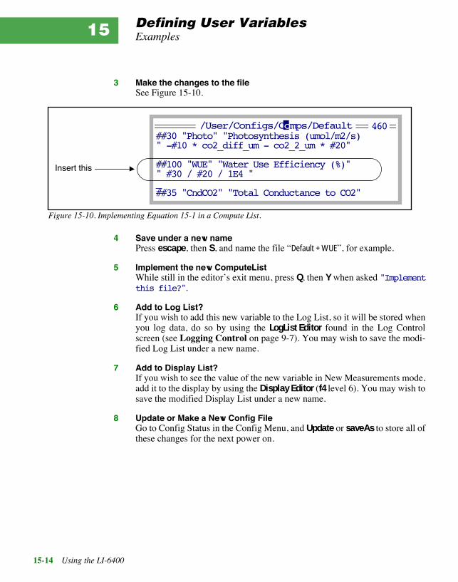
Defining User VariablesExamples
15-14 Using the LI-6400
15
3 Make the changes to the fileSee Figure 15-10.
4 Save under a new namePress escape, then S, and name the file ÒDefault + WUEÓ, for example.
5 Implement the new ComputeListWhile still in the editorÕs exit menu, press Q, then Y when asked "Implementthis file?".
6 Add to Log List?If you wish to add this new variable to the Log List, so it will be stored whenyou log data, do so by using the LogList Editor found in the Log Controlscreen (see Logging Control on page 9-7). You may wish to save the modi-fied Log List under a new name.
7 Add to Display List?If you wish to see the value of the new variable in New Measurements mode,add it to the display by using the Display Editor (f4 level 6). You may wish tosave the modified Display List under a new name.
8 Update or Make a New Config FileGo to Config Status in the Config Menu, and Update or saveAs to store all ofthese changes for the next power on.
##30 "Photo" "Photosynthesis (umol/m2/s)" -#10 * co2_diff_um - co2_2_um * #20"
##100 "WUE" "Water Use Efficiency (%)"" #30 / #20 / 1E4 "_##35 "CndCO2" "Total Conductance to CO2"
Figure 15-10. Implementing Equation 15-1 in a Compute List.
Insert this
460/User/Configs/Comps/Default

Defining User VariablesUseful Variables and Functions
Using the LI-6400 15-15
Useful Variables and Functions
Table 14-8 on page 14-19 contains variable names for the System Variables.Table 15-3 gives some useful functions.
Table 15-3. Some Useful Functions and Operators
Function Description
+ Add
- Subtract
* Multiply
/ Divide
^ Raise to a power
LOG(x) natural log of x
LGT(x) log base 10
CHS(x) changes sign of x
ABS(x) absolute value of x
SQRT(x) square root of x
EXP(x) exponential.
SatVap(T) Returns saturation vapor pressure (kPa)T - temp (C)
StdCond(E, Tf, Blc, P, W) Returns stomatal conductance (mol m-2 s-1)E - transpiration (mol m-2 s-1)Tf - leaf temp (C)Blc - boundary layer cond (mol m-2 s-1)P - atmos pressure (kPa)W - ambient water vapor (mmol mol-1)
DewPoint(e) Returns the dewpoint temperature (C)e - vapor pressure (kPa)
EB_DeltaT(Rn, Tw, Ta, Blc, E) Returns Tleaf - Tair from energy balance.E - transpiration (mol m-2 s-1)Blc - boundary layer cond (mol m-2 s-1)Ta - Air temp (C)Tw - Chamber wall temp (C)Rn - Net radiation (W/m2)

Defining User VariablesThe Default ComputeList
15-16 Using the LI-6400
15
The Default ComputeListThe default ComputeList is shown in Figure 15-11
##10 "(U/S)" "flow:area ratio" " flow_um / area_cm2 / 100.0"
##20 "Trans" "Transpiration (mol/m2/s)" " #10 * (h2o_2_mm - h2o_1_mm) / (1000.0 - h2o_2_mm)"
##21 "Trmmol" "Transpiration (mmol/m2/s)" " #20 * 1E3"
##23 "Cond" "Stomatal cond. (mol/m2/s)" " StdCond(#20, Tleaf_c, condBL_mol, press_kPa, h2o_2_mm)"
##30 "Photo" "Photosynthesis (umol/m2/s)" " -#10 * co2_diff_um - co2_2_um * #20"
##35 "CndCO2" "Total Conductance to CO2" " 1.0 / (1.6 / #23 + 1.37 / condBL_mol)"
##36 "Ci" "Intercellular CO2 (umol/mol)" " ((#35 - #20/2) * co2_2_um - #30) / (#35 + #20/2)"
##38 "Ci_Pa" "Intercellular CO2 (Pa)" " #36 * press_kPa * 1E-3"
##39 "Ci/Ca" "Intercellular CO2 / Ambient CO2"" #36 / co2_2_um "
##25 "VpdL" "Leaf VPD (es(Tleaf) - eair)"" SatVap(Tleaf_c) - eAir_2_kPa"
##27 "VpdA" "Air VPD (es(tair) - eair)"" satVapTair_kPa - eAir_2_kPa"
Figure 15-11. Listing of file /User/Configs/Comps/Default

Defining User VariablesOld Style vs. New Style
Using the LI-6400 15-17
Old Style vs. New StyleThe discussion up to this point, especially concerning the format of Com-puteList files, involves the ÒOld StyleÓ. Until OPEN version 3.0, the OldStyle was the only style. The need for increased flexibility, to support devicessuch as the Soil Flux chamber, gave rise to an alternative format Com-puteList, which is termed the ÒNew StyleÓ.
Essentially, the new style ComputeList is one that is directly written in LPL,the LI-6400Õs programming language (see Chapter 22). When an old styleComputeList is used, OPEN converts it into a new style, then links it. If youuse a new style to start with, this step is eliminated.
Further details are provided in New Style ComputeList Files on page 26-16.

Defining User VariablesOld Style vs. New Style
15-18 Using the LI-6400
15

Using the LI-6400 16-1
16Configuration Basics
What you need to know to get by
A DEFINITION OF TERMS 16-2Configuration Files 16-2Configuration Commands 16-3Master and User Files 16-3
MAKING CONFIGURATION FILES 16-4The Installation Menu 16-4Two Examples 16-5
INSTALLATION MENU: BEHIND THE SCENES 16-10Installing a Sensor 16-10Using Energy Balance 16-11Boundary Layer Conductance 16-12
MODIFYING CONFIG FILES 16-12Config Status 16-14Config Editor 16-15
THE RESET MENU 16-16ÒConfig File (Re-)InstallÓ 16-16 ÒReset to Factory DefaultsÓ 16-18ÒReset to User Configuration 16-18
CONFIGURATION COMMAND SUMMARY 16-18

Configuration Basics
16-2 Using the LI-6400
16In the early days of the LI-6400, there was but one way to do any configura-tion change: go to the Config Editor. While this tool is still available as a lastresort, more recent versions of software have introduced various configura-tion ÒhelpersÓ, such as Logging Control (page 9-7), Prompt Control (page9-12), and Light Source Control (page 8-4).
The purpose of this chapter is to explain OPENÕs configuration scheme, andhow the various configuration helpers fit into it. We also describe anotherhelper, the Installation Menu. It has itÕs own guided tour in an earlier chapter(see page 3-51), but we give the details here. Finally, we document the gen-eral purpose configuration tool, the Config Editor.
A Definition of TermsConfiguring OPEN for making the measurements that you want covers a va-riety of issues, including the proper calibration constants for the sensors beingused, the mix of variables you want stored, and the particular equation set thatyou deem appropriate, to name but three. All of these are handled by one ve-hicle: the configuration file.
Configuration FilesWhen OPEN is first run, one of the things that happens is the selection andimplementation of a configuration file. This may happen automatically, ormay involve user assistance. If multiple configuration files exist, the user isasked to select one from a menu (Figure 16-1). The default configuration fileis named Factory Default, and if that is the only one found, it is used without firstprompting the user to select it.
So what, then, is a Configuration File? It is simply a collection of configura-tion commands that specify changes to the default settings. While there areabout 30 possible configuration commands, usually only a few are found in aconfiguration file.

Configuration BasicsA Definition of Terms
Using the LI-6400 16-3
Configuration CommandsThree sample configuration commands are listed in Figure 16-2.
A configuration command consists of a string terminated by =, followed by aspace. The number or text that comes next is the value of the command. Thecomplete list of configuration commands, and what they mean, is given inConfiguration Command Summary on page 16-18.
Master and User FilesOPEN has stored away in the file system a master file of configuration com-mands, and these comprise the factory default settings1. Whenever OPEN im-plements a configuration, this master file is first read and implemented.
1.In case youÕre interested, this master ÒfileÓ is actually two files: Ò/Sys/Open/Con-fig Items 1", and Ò/dev/parm0Ó.
Figure 16-1. Prompting the user for a configuration file. This can happenat power up, or when Resetting to User Configuration (from the ResetMenu, found in the Config Menu).
DIR: /User/Configs/UserPref
"Conifer Chamber"
"Soil Chamber"
Select a Configuration File
+ Dir Cancel Select+
"Factory Default"
AREA= 6.0LogFile= /User/Configs/LogFormat/MineFanSlow= 4
Command ValueSpace
Figure 16-2. Three sample configuration commands. A command has an =as the last character, and is followed by a space, then the value.

Configuration BasicsMaking Configuration Files
16-4 Using the LI-6400
16
Following that, a user file is read and implemented. If the user file is empty(a legitimate possibility, and in fact the file Factory Default is empty), then theresulting configuration is the factory default. Usually, though, the user fileconsists of a handful of configuration commands that, because it is read last,override the corresponding settings of the master list. Figure 16-3 illustratesthe relationship between the master and user files.
Making Configuration Files
The Installation MenuThe simplest method of building a configuration file appropriate for someconfiguration is to use the Installation Menu (Figure 16-4). Anytime you wishto add the calibration of an accessory, such as an external quantum sensor,chamber light sensor, LED light source, etc., or generate a configuration filethat makes use of a different chamber or other accessory, then select the itemin question from the Installation Menu, and follow the ensuing directions.
Note: In OPEN 3.01, there is a potential problem with using the InstallationMenu for installing external quantum sensors, or LED light sources, if it is thefirst one being installed. The problem is that the calibration file can becomecorrupted. See ÒUnknown config commandÓ on page 20-5.
Figure 16-3. The master list is implemented first, then the user list. User list commands thus overridemaster list settings.
AREA= 6.0AvgTime= 4FanSlow= 4CO2Mixer= No
AREA= 12FanSlow=3
Master File User File
ÉÉ
AREA= 12AvgTime= 4FanSlow= 3CO2Mixer= No
Result
ÉÉ

Configuration BasicsMaking Configuration Files
Using the LI-6400 16-5
The Installation Menu is a powerful tool that can save you time and grief.Suppose, for example, you were going to use a clear bottomed 2x6 chamber,and wanted to configure the LI-6400 accordingly. If you were some sort of aLI-6400 guru, you might be able to go to the Config Editor and build one fromscratch2, keeping in mind the following issues: leaf temperature is no longermeasured, so you need an energy balance computation; itÕs a 2x6 chamber, sothe boundary layer conductance is different; if youÕre measuring needles in-stead of broadleaves, the boundary layer is different again. However, a morenormal person could just go to the Installation Menu, select Ò6400-08 Clear2x3 BottomÓ, answer some questions, and produce a proper configuration,without having to know any arcane details.
Two ExamplesWe present two examples of using the Installation Menu to build configura-tion files.
■■■■ Example: 6400-02B LED SourceSuppose you already have a 6400-02 red LED source, but you have acquireda 6400-02B source as well. This example will show you how to install it, andeasily switch configurations from one to the other.
"6400-02 or -02B LED Source""6400-05 Conifer Chamber""6400-06 PAM Interface""6400-07 or -11 2x6 Chamber""6400-08 Clear 2x3 Bottom""6400-09 Soil Chamber""6400-10 MiniPAM Interface""6400-13 TC Adapter""6400-14 OptiSciences""External Quantum Sensor""Std 2x3 Chamber Top""View Installed Cal Items""Configuration Examples Menu"
Figure 16-4. The Installation Menu can be used to add calibration factors of newly acquired accessories and togenerate or modify a configuration to use that accessory.
The ÒView Installed...Ó entry lists all installed accessories that have a calibration. Check this to see if a particular item has al-ready been installed. Items can also be re-moved using ÒView Installed...Ó.
Installation Menu
2.This guru wouldnÕt try. HeÕd just use the Installation Menu.

Configuration BasicsMaking Configuration Files
16-6 Using the LI-6400
16
1 Select Ò6400-02 or -02B LED SourceÓ This is in the "Installation Menu", which is in the Config menu.
2 Is the calibration already installed?YouÕll be shown a list of installed 6400-02 and -02B calibration factors(Figure 16-5). If the one you are using is shown, press Y and go to step 4. Oth-erwise, press N to indicate that it is not shown, then Y to add it now.
3 Add the calibration informationYouÕll need the calibration sheet (Figure 16-6) for the next three questions:
Installed 6400-02 or -02B LED Sources: 0.47 // SI-183 10 Oct 1996
Does the serial number of the item to be installed appear above? (Y/N) NDo you wish to add it now? (Y/N) Y
your responses
Figure 16-5. The LED source installation program shows the currently installedsources, and gives you the chance to add to the list.
6400-02B LED Light SourceCalibration CertificateSerial Number SI-505
Date: 6 June 1997 Technician
CalParLED= -.59
Figure 16-6. The required calibration information is available from the lightsourceÕs calibration sheet.
1
2
3

Configuration BasicsMaking Configuration Files
Using the LI-6400 16-7
This information is entered using three prompts:
When prompted
ÒIs this OKÓ,
confirm the information entered with a Y or N. (If you press N, you will beasked for the three items in step 3 again.)
Once a 6400-02 or -02B calibration is installed, you can readily change anyexisting configuration to use it, by using the Light Source Control (page 8-4).However, you may wish to build a configuration for it, which you can do withthe Installation Menu. Continuing our exampleÉ
4 Build the configuration filePress Y when asked
Build a configuration file? (Y/N)
5 Specify the chamber bottomYouÕll be asked to specify which chamber bottom is being used (either thestandard 2x3 chamber bottom or the clear bottomed 6400-08 2x3).
6 Specify the light sourceYouÕll be asked to select a light source from a menu (Figure 16-7) which willcontain all installed LED sources, in addition to some standard sources.
6400-02B or -02B LED Light SourceEnter serial number: SI-505Enter calibration value: -0.59Enter cal date: 6 June 1997
Ò6400-02B RedBlue #SI-505ÓÒSun+SkyÓ 1.0 0.19ÒQuartz HalogenÓ 1.11 0.26ÒFluorescentÓ 0.88 0.18ÒMetal HalideÓ 0.87 0.17
Select Light SourceÒ6400-02 Red LED #SI-183Ó
Figure 16-7. The light source menu includes standard sources, plus whatever6400-02 and -02B sources have been installed.

Configuration BasicsMaking Configuration Files
16-8 Using the LI-6400
16
7 Leaf Temp: Measured or Energy Balance (M/E)?Specify how the leaf temperature is to be made (if you selected the clear bot-tomed chamber, it wonÕt ask this)
Leaf Temperature:Measured or Energy Balance ? (M/E) E
If the chamber has a clear bottom or is the conifer chamber, an energy balanceis always used, since there is no leaf temperature thermocouple present. Oth-erwise, you have a choice between measuring leaf temperature directly, or us-ing the thermocouple to measure air temperature and computing the leaftemperature with an energy balance. The latter is useful for non-flat plant ma-terial, such as needles. The response here determines a number of configura-tion commands, including ÒComputeList=Ó, ÒLogFormat=Ó, and ÒDisplay=Ó
8 Leaf Type: Needles or Broadleaves (N/B)?The response to the question
Enter leaf typeNeedles or Broadleaves (N/B)?
determines if the boundary layer conductance will be computed from a look-up table (broadleaves), or if a fixed value is used (needles). The ÒBLCond=Óconfiguration command is set by this response.
9 View the config fileYou are then shown what the config file will look like (Figure 16-8).
Press escape when done viewing the file.
BLCond= 5AREA= 2LightSource= Ò6400-02B RedBlue #505ComputeList= ÒDefault using EBÓDisplays= ÒStd+EBTleafÓLogFormat= ÒStd+EBÓ
The Config (press <esc>)
Figure 16-8. After building a configuration, you are given achance to view it before storing or discarding it.

Configuration BasicsMaking Configuration Files
Using the LI-6400 16-9
10 Store the Config FilePress Y when asked if you wish to store the file. A default name is providedwhich captures the essence of the configuration (Figure 16-9).
You may wish to modify the default name to specify that it is for the Red/BlueLED Source.
To implement the configuration, select ÒReset to User ConfigÓ from theReset Menu in the Config Menu.
■■■■ Example: 6400-09 Soil ChamberThe 6400-09 has no calibration factors to install, so the installation is a simple2-step process:
1 Select Ò6400-09 Soil ChamberÓ From OPENÕs main screen, press Config Menu (F2), then select the Installa-tion menu.
2 View the filePress escape when done.
3 Store the filePress Y to store the file. Modify the default ÒSoil ChamberÓ name if you desire.
The installation program will then copy some other support files from /sys to/user, and you are done.
None of the configurations that can be generated by the Installation Menu ac-tually take effect until you select them after a) power on, or b) you select"Reset To User Configuration", found in "_Reset Menu", in the ConfigMenu.
2x3 Opaque Needles LED EB
energy balanceLED Source
chamber bottomchamber size
Figure 16-9. The default file name for a generated configuration file in-cludes several details. You can use it, modify it, or invent your own name.
fixed BLC value

Configuration BasicsInstallation Menu: Behind the Scenes
16-10 Using the LI-6400
16
Installation Menu: Behind the ScenesWhat actually happens when you use the Installation Menu to install a newsensor, or build a new configuration file?
Installing a SensorAny item that has a calibration associated with it (chamber tops, LED sourc-es, external PAR sensors) needs to be ÒinstalledÓ, which simply means thatthere needs to be an entry in a certain file that contains all the calibration in-formation. That file is Ò/dev/parm0Ó, and itÕs contents make up part of the mas-ter list illustrated in Figure 16-3 on page 16-4. A typical Ò/dev/parm0Ó is shownin Figure 16-10.
The Installation Menu entry "View Installed Cal Items" scans “/dev/parm0”for the following entries (commented or not):
CalParGaAs=CalParLED=CalParOut=
and presents the results in a list such as shown by Figure 16-11.
// Calibration Data G103950109CO2Mixer= YESCalCO2= 0.21732 2.1807E-05 1.9303E-08 -3.2863E-12 3.272E-16CalH2O= 0.0063802 1.9083E-06 -2.4303E-11 CalZero= -4.0 -2.3 CalFlow= 0.35307 CalPress= 88.522 0.005458 CalParGaAs= 0.77 // GA-103 20 Jan 1995// CalParGaAs= 0.70 // GB-244 07 Jul 1996CalParLED= 0.48 // SI-120 10 Jun 1995CalParLED= -0.54 // SI-501 27 Jul 1997CalParOut= 5.78 // Q13436 27 Aug 1990ThisUnit= "PSC-0103"Serviced= "9 Jan 1995"
Figure 16-10. Listing of a typical Ò/dev/parm0Ó. This file contains calibration data for all sensors.When you install sensors using the Installation Menu, the data you enter winds up here. When thereare multiple sensors of one type, the ÒextraÓ ones can either appear as comments (line starts with //),or come first in the list (the last one will take precedence).
ÒExtraÓ

Configuration BasicsInstallation Menu: Behind the Scenes
Using the LI-6400 16-11
■■■■ To Edit The Calibration Data Directly
1 Access the FilerFrom the LPL screen, or else from OPENÕs Utility Menu.
2 Run the program Verify CalibrationItÕs in the directory Ò/Sys/UtilityÓ, and discussed on page 21-20.
Using Energy BalanceWhen you build a configuration file using the Installation Menu, and areasked if leaf temperature is to be measured or computed, selecting the latterwill cause an energy balance to be implemented. Energy Balances are dis-cussed in Chapter 17, and their implementation via the ComputeList is dis-cussed in Chapter 15. There are three standard energy balance files that mightget used:
Clear Bottom EBConifer Chamber EBDefault using EB
The configuration builder sets the ComputeList= configuration command tothe appropriate file, based on what chamber you are using, and/or how youanswered the energy balance question. The 6400-05 Conifer chamber, and theclear bottom chambers, always use an energy balance.
0.48 // SI-120 10 Jun 1996 -.54 // SI-501 27 Jul 1997Chamber Light Sensor(s)..(CalPARGaAs=) 0.77 // GA-103 20 Jan 1995 0.70 // GB-244 07 Jul 1996Extrnl Quantum Sensor(s)..(CalPAROut=) 5.78 // Q13436 27 Aug 1990
Installed Options
Figure 16-11. A summary of light sensor related calibrations is available byselecting ÒView Installed Cal ItemsÓ in the Installation Menu.
6400-02 & -02B LED(s)...(CalParLED=)
Removes the highlighted entry from Ò/dev/parm0 Ò
Remove OK

Configuration BasicsModifying Config Files
16-12 Using the LI-6400
16
Boundary Layer ConductanceWhen the Installation MenuÕs configuration builder asks you about broadle-aves or conifers, it is determining what default area to use, and how to handleboundary layer conductance calculations. If you are measuring broadleaves,then the configuration command BLCond= will be set to one of these twolookup tables:
StdBLCTableBLCTable_2x6
Both are stored in the Ò/sys/lib Ò directory. If you specified conifers, a fixedvalue of 5 is used instead of the lookup table. (If you have a better value, youcan use the Config Editor and enter it.)
Modifying Config FilesThe general purpose tool for building or editing a user configuration file is theConfig Editor (page 16-15). Frequently, however, it is not necessary to resortto this to accomplish what you want. The Logging Control screen (page 9-7),Prompt Control screen (page 9-12), and LightSource Control screen (page8-4) are examples of ways to affect the user config file without using the Con-fig Editor.
Table 16-1. Methods of modifying config files
Action Affected Configura-tion Command
AREA (F1 level 3) New Msmnts Mode AREA=
STOMRT (F2 level 3) New Msmnts Mode StomRat=
Display QuikPik (F2 level 6) New Msmnts Mode Displays=
Pick Source (F1) in Light Source Control LightSource=
LogList QuikPik (F2) in Logging Control
LogFormat=SaveAs (F5 level 2) in LogList Editor
LogList QuickPik (F5 level 5) New Msmnts Mode
LogList QuikPik (F2) in Prompt ControlPromptList=
SaveAs (F5 level 2) in PromptList Editor
ÒChoose a Compute ListÓ in ComputeList Menu ComputeList=
GRAPH QuikPik (F2 level 4) New Msmnts Mode StripDefs=
SaveAs or OK in Config Editor Any command

Configuration BasicsModifying Config Files
Using the LI-6400 16-13
An indication that the current configuration has been changed, but is notstored, is the presence of the CONFIG flag in OPENÕs main screen(Figure 16-12). An unstored configuration will be lost at power off, so if youwish to keep the changes for the next session, or to store the changed config-uration as a new configuration file, then this can be done with the Config Sta-tus, described on page 16-14.
/User 66% fullTue Jun 16 1998 12:29:36 12.25V
Menu Menu Menu Msmnts MenuWelcome Config Calib New Utility
LI-6400 Photosynthesis SystemOPEN 3.2
CONFIG
Figure 16-12. When the configuration is changed and not stored, the CONFIG flagwill appear in OPENÕs main screen. Too see what the change is, and to store theconfiguration, go to Config Status in the Config Menu.
Indicates a modi-fied and unstored configuration

Configuration BasicsModifying Config Files
16-14 Using the LI-6400
16
Config Status"Config Status" in the Config Menu shows a screen that indicates the cur-rent user config file name, and what changes, if any, have been made sincethis file was last stored (Figure 16-13).
Config Status. Current Config Is:Factory Default
Edit Quit
If the current configuration file is saved:
File Contents. (Note that ÒFactory DefaultÓ is an empty file.)
Config Status. Current Config Is:Factory Default
Edit Save saveAs Revert Quit
If the current configuration file is NOT saved:
File Contents. ---------- as stored ----------
---------- changes (1) --------LightSource= Ò6400-02B RedBlue #SI-55
Unstored Changes
Access the Config Editor.
Update and Save the Config File
Access the Config Editor.
Revert back to the Ôas storedÕ version
Update and Save the Config File under a new name.
Figure 16-13. The Config Status screen shows the user config file, and (if it has been modified and is un-stored), what the changes are to it.

Configuration BasicsModifying Config Files
Using the LI-6400 16-15
Config EditorThe Config Editor is essentially a dialog box, in which the user is shown thecurrent user configuration items in a list. The user can make modifications,create new configuration files, recall and edit other configuration files, andimplement a different configuration.
The Configuration Editor is driven by function keys, whose definitions aregiven in Table 16-2.
Table 16-2. The Config EditorÕs function keys
Key Action
Add If you donÕt see an item in the config file, you can add it withthis key. The items of the master file are shown to you as amenu, and you may select the desired item to be added toyour config file. Once it is added, you can then edit it if nec-essary.
Edit Change the highlighted entry in the config file. What actual-ly happens depends on the item being edited. Edit might ac-cess a menu of possibilities (e.g. LogDelimiter=), or promptfor a new value (e.g. AREA=), or access the Standard FileDialog box (e.g. Displays=).
Remove Remove the highlighted entry. This is functionally equiva-lent to (and more efficient than) setting it to the factory de-fault value.
Disable Disables a config command without removing it by turningit into a comment. (Config comments start out with twoslashes - //).
Enable Removes the slashes from a commented config command.
SaveAs. Store the file under a new name. You are prompted for a filename using the Standard File Dialog box, and if a file is spec-ified, the config file is stored as that file name.
Open... The user is prompted for a file name using the Standard FileDialog box, and if a file is selected, the file is read in to beedited, replacing the current config file.
Cancel Abandon the config editor, and make no configurationchanges.
OK Implement the current contents of the config editor, and up-date the file.

Configuration BasicsThe Reset Menu
16-16 Using the LI-6400
16
A complete list of configuration commands is given below in ConfigurationCommand Summary.
When the Config Editor is exited using Cancel, no configuration changes aremade. When the Config Editor is exited using OK, the an exit screen(Figure 16-14) will appear if editing changes have been made to the configfile. You can save the file, save the configuration as a new file, or abandonthe whole thing.
Pressing S or A will implement the configuration file; the only difference iswhat name the configuration file will have. Pressing C will be the same as ex-iting via Cancel.
The Reset Menu
ÒConfig File (Re-)InstallÓThis program will set some or all of the default configuration files back to fac-tory defaults. It can be used to undo changes you might have made to thesefiles, or to get the /User disk back into a usable form after it has been format-ted, or install a default configuration onto an arbitrary disk (such as the hiddendisk after it has been brought on-line).
After the program opening message, you are asked to choose a destination.
Typically this would be User. The disk selected will then have a directory cre-
(S/A/C)
Config has changed
Figure 16-14. The exit options when leaving the Config Editor after changinga configuration.
Save As a new fileSave Õ<file name>Õ
Cancel changes
ÒSysÓChoose a destination
ÒUserÓ

Configuration BasicsThe Reset Menu
Using the LI-6400 16-17
ated in its root named Config, if one is not already there. You are then asked
Do a full installation? (Y/N)
If you press Y, all files will be copied from where they reside on the /Sys disk,to your destination disk. If you press N, you can select which types of files areto be copied over. You are prompted for these in sequence:
Do AutoPrograms? (Y/N)Do User Computations? (Y/N)Do Display Formats? (Y/N)Do Log File Formats? (Y/N)Do QuikPlot Definitions? (Y/N)Do Prompt Lists? (Y/N)Do Strip Chart Definitions? (Y/N)Do Config Files? (Y/N)
The files involved are listed in table Table 16-3.
Table 16-3. Files installed by Config File Reinstall.
Category Destination directory Files to be overwritten
AutoPrograms Configs/AutoProgs AutoLogAveraging AutoLogLightCurve A-CiCurveBuffered AutoLogTimedLampRemote Control
User Computations Configs/Comps DefaultDefault using EBClear Bottom EBConifer Chamber EB
Display Formats Configs/Displays Std DisplayStd+EBTleafDiagnostic
Log File Formats Configs/LogFormats Std OutputStd+EB
QuikPlot Definitions Configs/PlotDefs Photo, Cond vs ObsLight Curve A Ci Curve
Prompt Lists Configs/Prompts Default (none)

Configuration BasicsConfiguration Command Summary
16-18 Using the LI-6400
16
ÒReset to Factory DefaultsÓThis program is designed to put the LI-6400 into a ÒknownÓ state quickly. Itsimply implements the master list without any user list. It is functionallyequivalent to ÒReset to User ConfigÓ, and selecting “Factory Default” (provid-ed “Factory Default” is an empty file).
The user is prompted for one thing:
Re-install config files? (Y/N).
Pressing Y will reinstall the configuration files (on the current config disk,typically /User). Pressing N will skip that, and pressing escape will abort.
ÒReset to User ConfigurationThis program allows the user to select a configuration (provided there is morethan just “Factory Defaults” in the “Configs/UserPrefs” directory. After implement-ing the master list, the user is prompted to select a configuration (Figure 16-1on page 16-3), and it is then implemented.
Configuration Command SummaryThe following commands can be used in a configuration file. For the most upto date list valid for whatever version of OPEN you are running, press theHelp function key in the Configuration Menu. There may be changes de-scribed there that occurred after this writing.
AREA=Sets the leaf area parameter. Note that this can be set in New Measurementsmode as well. Leaf area is a system variable (ID number -33).
Strip Chart Definitions Configs/StripDefs Photo & CondDeltaCO2, DeltaH2O, FlowA-Q, g-Q, totalCVA-Q, RH-Flow, totalCVA-Ci, RH-Flow, totalCVA-Ci, totalCV, CO2S
Config Files Configs/UserPrefs Factory Default
Table 16-3. (Continued) Files installed by Config File Reinstall.
Category Destination directory Files to be overwritten

Configuration BasicsConfiguration Command Summary
Using the LI-6400 16-19
AutoProgs= Default auto program. The default value is Ò_Ó. This does not specify a file,so the first file in Ò/user/Configs/AutoProgsÓ will be highlighted the first time theAutoProg menu is accessed (New Measurements mode, f1 level 5).
AvgTime=Running average time (seconds) for IRGA measurements. The running aver-age time for all other channels is 1 second. The default IRGA signal averagetime is 4 seconds. This is for noise reduction.
BLCond= Specify either a fixed value for the one-sided boundary layer conductance touse, or else the file name of the lookup table to use. See Boundary LayerVariables on page 14-17 for the equations. The default setting
BLCond= "/Sys/Lib/StdBLCTable"
is appropriate for broadleaves in the 2x3 chamber, and allows the effectiveboundary layer conductance to be computed automatically as a function ofleaf area and fan speed. When using a 2x6 chamber (6400-07 or 6400-11),then use
BLCond= "/Sys/Lib/BLCTable_2x6"
If you are using conifers, then a fixed value is more appropriate:
BLCond= 5
BndBrdCorr= Use band broadening corrections (page 14-23) for water vapor when comput-ing CO2 concentrations? A Yes/No toggle. Default is Yes, and there is prob-ably no good reason why it should be changed.
CalCO2= CO2 IRGA cal coefficients, for Equations (14-8) and (14-9) on page 14-6.These coefficients for a 5th order polynomial with no 0-order term are gener-ated at the factory, and there is probably no good reason for you to changethem. (If you are thinking about interchanging IRGA/sensor heads, donÕt.)
CalH2O= H2O IRGA cal coefficients for Equations (14-5) and (14-6) on page 14-5.These are coefficients for a 3rd order polynomial with no 0-order term.

Configuration BasicsConfiguration Command Summary
16-20 Using the LI-6400
16
CalFlow= Flow meter calibration multiplier for the linear flow meter, Equation (14-13)on page 14-7.
CalPress= Pressure sensor calibration offset and multiplier for the linear pressure sensor,Equation (14-1) on page 14-4.
CalParGaAs= GaAsP sensor calibration factor ag. See In-Chamber PAR on page 14-8.
CalParOut= External PAR calibration factor aqx, in Equation (14-16) on page 14-8.
CalParLED= LED source sensor calibration factor ae in Equation (14-15) on page 14-8.Note that since version 3.0 of OPEN, ae is specified in the calibration file us-ing the CalParLED= command, but typically is specified in a user config fileas part of the LightSource= command. Thus, there is no longer any reason forCalParLED= to appear in a user configuration file.
If for some reason, a configuration file contains a LightSource= commandthat specifies an LED source with one value of ae, and also a CalParLED=that specifies another value of ae, the one that takes precedent is whicheverone is last in the file.
CalZero=The two values which follow specify IRGA zero drift with temperature forCO2 and H2O respectively. The values correspond to Sc and Sw in Equations(14-10) and (14-7) starting on page 14-5.
ComputeList= File containing user equations (Chapter 15). The user equations are not actu-ally recompiled unless the file name or the file modification date has changedsince power on. If no directory is specified, then Ò/User/Configs/CompsÓ is as-sumed.
CO2Mixer= Is the CO2 mixer installed? This is also a Yes/No toggle, and should be set toreflect whether the mixer is installed or not; it has nothing to do with whetheryou are actually using the mixer.

Configuration BasicsConfiguration Command Summary
Using the LI-6400 16-21
Displays=The display format file. If no directory is specified, then Ò/User/Configs/DisplaysÓis assumed.
FanSlow= Volts for slow fan speed. 0 is off, 5 is full speed. We recommend 4 for theslow value, so thatÕs the default value.
LightSource= Specifies the light source in use. When edited in the Config Editor, this entryis selected from a menu of possibilities (Figure 16-7 on page 16-7). This com-mand requires multiple values. For non-LED sources:
LightSource= <name> fa B
where fa is an actinity correction factor (Equation (14-15) on page 14-8), andB is used to convert incident PAR to absorbed energy (Table 17-1 on page17-4) for energy balance calculations. If the source is an LED source (a6400-02 or -02B), then a third parameter ae is expected:
LightSource= "6400-02É" fa B ae
where ae is the light sourceÕs calibration factor (Equation (14-15) on page14-8). This quantity has historically been specified with the CalParLED=command, but since OPEN version 3.0 and the introduction of the LightSource Control utility, it can also be included in the LightSource= command.
LogDelimiter=Data field delimiter to use in log files. The editor for this item lists a menu,the contents of which are stored in the file Ò/Sys/Lib/Delims Ò.
LogFile= Initial default log file name. Once the user opens a log file, his choice be-comes the default for the next time a file is opened.
LogFormat= The logList file, identifying the variables to be stored in a log file. If no direc-tory is specified, Ò/User/Configs/LogFormatÓ is assumed.
PATCH=This is a catch-all tool. Whatever comes after the = is compiled (using LPLÕsCOMPILE keyword) and run. The usual use for this is to set variables from

Configuration BasicsConfiguration Command Summary
16-22 Using the LI-6400
16
the configuration menu that donÕt have a normal interface. Sample uses ofPatch= are shown in Figure 16-15.
PlotDefs= Default plot axes definitions. If no directory is specified, /User/Configs/PlotDefsis assumed.
Prompts=(OPEN 3.2) Toggles between ÒoffÓ and ÒON LOGÓ. Determines if theprompt list (if any) will be prompted for when data is manually logged.
StripDefs= Default strip chart config. If no directory is specified, /User/Configs/StripDefs isassumed.
StomRat=Sets the stomatal ratio parameter K (Equation (14-31) on page 14-17). Notethat this can be set in New Measurements mode as well (f2 level 3).
UserChan=The three values following the command are signal channel (20 through 23),ground channel (3 through 7), and resolution (0 = low, 1 = high). See AnalogInput Channels on page 26-22.
//This marks a comment. Any line starting with // is ignored. Note that the En-able and Disable function keys in the Config Editor comment and uncom-ment lines in this manner.
PATCH= 0 &logBeepTime =PATCH= 200 &logBeepTime =PATCH= 3400 10 AOSETPATCH= 1 0x0401 DIOSET
Turn off log beeps
Set log beep duration to 200 mS
Figure 16-15. Some example uses of the Patch= command
Set D/A port 10 to 3400 mV
Set digital port 4, pin 1 high.

Using the LI-6400 17-1
17Using an Energy Balance
Computing what you canÕt measure
THE THEORY 17-2
USING ENERGY BALANCE IN OPEN 17-6How To Do It 17-6The Details 17-6Recomputation Considerations 17-9
ENERGY BALANCE AND BOUNDARY LAYER 17-9
FURTHER READING 17-11

Using an Energy Balance
17-2 Using the LI-6400
17Sometimes it is not convenient or even possible to measure leaf temperaturewith thermocouple. LI-6400 chambers that do not measure leaf temperaturedirectly are the 6400-05 Conifer Chamber, the 6400-07 Needle Chamber, andthe 6400-08 Clear Bottomed Chamber. The method of getting leaf tempera-ture in these cases is to use an energy balance. This chapter explains the the-ory and the practice of using energy balance.
The TheoryThe energy balance of a leaf in the LI-6400 cuvette has three major compo-nents: net radiation R (W m-2), sensible heat flux Q (W m-2), and latent heatflux L (W m-2).
(17-1)
We consider two components to net radiation, solar and thermal( ). The solar part we will estimate by converting the
incoming PAR reading in the chamber RQ (µmol m-2 s-1) to total visible andnear IR energy using an empirical (measurable with a spectroradiometer)conversion factor k, and using the leaf absorptivity a averaged over the spec-trum of the light source.
(17-2)
The net thermal term is the difference in black body radiation balance, deter-mined by the chamber wall temperature Tw and the leaf temperature Tl.
(17-3)
where e is the thermal emissivity of the leaf, and s is the Stefan-Boltzmannconstant. The 2Õs in (17-3) account for both sides of the leaf. Latent heat fluxL is the transpiration rate E (mol m-2 s-1) converted to W m-2:
0 Q L R+ +=
R Rsolar Rthermal+=
Rsolar akRQ=
Rthermal 2es Tw 273+( )4
2es Tl 273+( )4
Ð=

Using an Energy BalanceThe Theory
Using the LI-6400 17-3
(17-4)
The sensible heat flux is a function of the leaf - air temperature difference, thespecific heat capacity of the air cP (J mol-1 K-1), and the one-sided boundary
layer conductance of the leaf gb (mol m-2 s-1)
(17-5)
The energy balance equation now becomes
(17-6)
If we let , and note that for small DT
(17-7)
then we can solve (17-6) for DT
(17-8)
where for most leaves, W m-2 K-1, and cP = 28 J
mol-1 K-1. While a and k can vary widely for different light sources(Figure 17-2 on page 17-5), their product is fairly conservative (Table 17-1).
L 44100E=
Q 2cpgb Tl TaÐ( )=
akRQ 2es Tw 273+( )4
2es Tl 273+( )4
Ð+
44100E 2cpgb Tl TaÐ( )+
=
DT Tl Taк
Tl 273+( )4
Ta 273+( )4
4 Ta 273+( )3
DT+»
DTakRQ 2es Tw 273+( )
4Ta 273+( )
4Ð 44100EÐ+
2cpgb 8es Ta 273+( )3
+-----------------------------------------------------------------------------------------------------------------------------------=
e 0.95» s 5.67 108Ð
´=

Using an Energy BalanceThe Theory
17-4 Using the LI-6400
17
.
Table 17-1. Radiation absorption coefficients for various light sourcesa
a.Measured with an LI-1800 spectroradiometer. Leaf spectralmeasurements were made on a green ash leaf using an 1800-12 In-tegrating Sphere.
Light Source k a
Sun + Sky 0.39 0.49 0.19
Mercury 0.33 0.60 0.20
Fluorescent 0.23 0.75 0.18
Tungsten 0.75 0.26 0.20
6400-02 LED (Red only)
0.18 0.84 0.16
6400-02B LED(Red + Blue)
0.19 0.84 0.15
Metal Halide 0.28 0.61 0.17
k a´ Bº
Figure 17-1. Leaf absortance spectrum used in the computations ofTable 17-1.
0
0.1
0.2
0.3
0.4
0.5
0.6
0.7
0.8
0.9
1
300 400 500 600 700 800 900 1000 1100
Abso
rpta
nce
(%)
Wavelength

Using an Energy BalanceThe Theory
Using the LI-6400 17-5
Figure 17-2. Spectra used to compute results in Table 17-1 on page 17-4. Vertical scales have units of
W m-2 nm-1 in all cases.
0
0.25
0.5
0.75
1
1.25
300 400 500 600 700 800 900 1000 1100
W m
-2 n
m-1
Wavelength (nm)
Cool White Fluorescent
0
5
10
15
20
25
300 400 500 600 700 800 900 1000 1100
W m
-2 nm
-1
Wavelength (nm)
6400-02B LED Source
0
0.5
1
1.5
2
2.5
3
300 400 500 600 700 800 900 1000 1100
W m
-2 n
m-1
Wavelength (nm)
Metal Halide
0
0.5
1
1.5
2
300 400 500 600 700 800 900 1000 1100
W m
-2 n
m-1
Wavelength (nm)
Sun+Sky
0
0.05
0.1
0.15
0.2
0.25
0.3
300 400 500 600 700 800 900 1000 1100
W m
-2 n
m-1
Wavelength (nm)
Tungsten
0
0.2
0.4
0.6
0.8
1
1.2
1.4
1.6
1.8
2
300 400 500 600 700 800 900 1000 1100
W m
-2 n
m-1
Wavelength (nm)
Mercury Vapor

Using an Energy BalanceUsing Energy Balance in OPEN
17-6 Using the LI-6400
17
Using Energy Balance in OPEN
How To Do ItDo the following to implement computing leaf temperature by energy bal-ance.
1 Use the Installation MenuItÕs in the Config Menu.
2 Select the chamber to be usedFrom the items in the Installation Menu, select the chamber you will be using.
3 Select Energy BalanceWhen asked if leaf temperature will be measured or computed, select the lat-ter.
4 Save the configuration, and change to itName the configuration, save it, and use the reset menu to implement it.
5 If there is a leaf temp thermocouple, use it for air tempIf you are using a chamber that uses a leaf temperature thermocouple, pull itdown so that it does not contact the leaf, but use it for getting air temperatureclose to the leaf. The 6400-05 Conifer Chamber, 6400-07 Needle Chamber,and 6400-08 Clear Bottomed chamber all have thermocouples expressly formeasuring chamber air temperature.
The DetailsEnergy balance computations are implemented via the ComputeList(Chapter 15). There are three factory-provided compute lists that use energybalance. When you use the Installation Menu to build a configuration, it willuse one of these compute lists. One of them, “Default using EB”, is shown inFigure 17-3 on page 17-7.

Using an Energy BalanceUsing Energy Balance in OPEN
Using the LI-6400 17-7
------ Energy Balance Leaf Temp Versions of default compute list -----
##10 "(U/S)" "flow:area ratio" " flow_um / area_cm2 / 100.0"
##20 "Trans" "Transpiration (mol/m2/s)" " #10 * (h2o_2_mm - h2o_1_mm) / (1000.0 - h2o_2_mm)"
---- Use TCham_c for wall temp, and leaf thermocouple for air temp ##100F2 "EBdT" "Energy Bal. Tleaf-Tair (C)"" EB_DeltaT( parIn_um * alphaK, tCham_c, tLeaf_C, condBL_one, #20) "
##101F2 "EBTlf" "Energy Bal. Tleaf (C)"" tLeaf_c + #100 "
##21 "Trmmol" "Transpiration (mmol/m2/s)" " #20 * 1E3"
##23 "Cond" "Stomatal cond. (mol/m2/s)" " StdCond(#20, #101, condBL_mol, press_kPa, h2o_2_mm)"
##30 "Photo" "Photosynthesis (umol/m2/s)" " -#10 * co2_diff_um - co2_2_um * #20"
##35 "CndCO2" "Total Conductance to CO2" " 1.0 / (1.6 / #23 + 1.37 / condBL_mol)"
##36 "Ci" "Intercellular CO2 (umol/mol)" " ((#35 - #20/2) * co2_2_um - #30) / (#35 + #20/2)"
##38 "Ci_Pa" "Intercellular CO2 (Pa)" " #36 * press_kPa * 1E-3"
##39 "Ci/Ca" "Intercellular CO2 / Ambient CO2"" #36 / co2_2_um "
##25 "VpdL" "Leaf VPD (es(Tleaf) - eair)"" SatVap(#101) - eAir_2_kPa"
##27 "VpdA" "Air VPD (es(tair) - eair)"" satVapTair_kPa - eAir_2_kPa"
Figure 17-3. Listing of ÒDefault using EBÓ. The energy balance leaf temperature is used inCond and VpdL.

Using an Energy BalanceUsing Energy Balance in OPEN
17-8 Using the LI-6400
17
Each of these compute lists add two new user variables, EBdT and EBTlf. Thefirst uses the LPL function EB_DeltaT() to compute the leaf-air temperaturedifference. This function implements Equation (17-8), takes five parameters,and returns the leaf-air temperature difference (Table 15-3 on page 15-15).
EB_DeltaT( parIn_um * alphaK, tCham_c, tLeaf_C, condBL_one, #20)
Absorbed EnergyThe first parameter is the energy absorbed by the leaf. The global variable al-
phaK is the product of the two multipliers ( and k) in (17-2). This productis given in Table 17-1 on page 17-4, and is set via the Lightsource= configu-ration command (page 16-21). The variable parIn_um is the current readingof the in-chamber light sensor.
If the chamber has a clear bottom, then the incident PAR would be larger thanmeasured by the uplooking chamber light sensor. For this reason, in the Com-puteList file ÒClear Bottom EBÓ, the call to EB_DeltaT looks a bit different:
EB_DeltaT( parIn_um * alphaK * 1.2,tCham_c,tLeaf_C,condBL_one,#20)
The parIn_um value is increased 20% to account for the clear bottom.
The third variation on the theme is provided by ÒConifer Chamber EBÓ, which hasno in-chamber PAR sensor, so the external one must be used. Accordingly,the call to EB_DeltaT looks like this:
EB_DeltaT( parOut_um * alphaK, tCham_c, tLeaf_C, condBL_one, #20)
Wall TemperatureThe second parameter needed for the EB_DeltaT function is wall tempera-ture. The LI-6400 doesnÕt have such a sensor per se, but the air temperaturethermistor is located in the IRGA beneath the air circulation fan. Between thislocation and the leaf chamber, the air comes in contact with a lot of metal wallmaterial, so this sensorÕs signal is not a bad first guess for wall temperature.However, the metal and Propafilm pieces of the leaf chamber itself will bemodified by external air, but we have no way of measuring that with the de-fault instrument. Thus, we use tCham_C for wall temperature. If the coolersare on, then the farther the set point is from ambient temperature, the worsethis assumption becomes. Fortunately, however, wall temperature is not thatcritical in the analysis.
a

Using an Energy BalanceEnergy Balance And Boundary Layer
Using the LI-6400 17-9
Air TemperatureThe third parameter is the air temperature next to the leaf. The LI-6400 hassensors for this only in the 6400-05, -07, and -08 chambers, so in the rest ofthe chambers we use the leaf thermocouple to do this job (variable tLeaf_C),by pulling it down a bit so that the junction is not in contact with any leaf ma-terial. Also, try to keep the junction shaded if possible to minimize radiationerrors.
Boundary Layer ConductanceThe fourth parameter is the one-sided boundary layer conductance, which isavailable as global variable condBL_one.
Transpiration RateThe final parameter is transpiration rate, which is user variable number 20.
If these assumptions are inadequate for your application, then you shouldmodify the ComputeList accordingly (and rename it to keep it separate).
Recomputation ConsiderationsThe recomputation option available in OPENÕs Utility Menu allows you tochange any of the following: user equations, output formats, absorbed radia-tion coefficients, area, boundary layer conductance, and stomatal ratio. Note,however, that if you use the leaf temperature thermocouple to measure airtemperature (as we recommend), then you canÕt go back and recompute with-out using the energy balance, because you will not have a measured leaf tem-perature.
Each of OPENÕs log files contains header information telling what user equa-tions, light source, output format, etc. were used for that file. Thus, you caneasily tell after the fact what mode you were in when looking at old data.
Energy Balance And Boundary LayerMeasuring the boundary layer conductance for broadleaves in LI-6400 cham-bers can be done using saturated filter paper to simulate a leaf. The problemwith this experiment, however, is that the leaf can be 10C cooler than the air,and the leaf temperature thermocouple will always underestimate that differ-ence, because of conduction errors along the wires.
We can bring an energy balance analysis to bear on this problem, with the ob-jective of finding an equation that will compute both leaf temperature, andboundary layer conductance. This requires the following simplifications:

Using an Energy BalanceEnergy Balance And Boundary Layer
17-10 Using the LI-6400
17
¥ There is no significant short wave energy incident on the filter paperRQ = 0 in (17-6). This requires doing the experiment indoors in room light.
¥ The only resistance to water leaving the paper is boundary layerThis is accomplished by making the filter paper is very wet, and allows us towrite
(17-9)
where the function e(T) computes saturation vapor pressure(Equation (14-21) on page 14-10), Tl is the filer paper temperature, and es isthe vapor pressure surrounding the paper (Equation (14-18) on page 14-9).Solving for one-sided boundary layer conductance gb,
(17-10)
and substituting that expression, along with RQ = 0 into (17-6) leaves us with
(17-11)
Solving (17-10) for E yields
(17-12)
Everything in Equation (17-12) is known except leaf (paper) temperature Tl.If Tl can be found by iteration, then boundary layer conductance can be deter-mined from (17-10). An LPL program is provided with OPEN that does im-plements this solution, and it is described in ÒENERGYBALÓ on page21-12. Its primary use is for doing boundary layer conductance determina-tions.
E 2gb
e T l( ) esÐ
P----------------------è ø
æ ö=
gbEP
2 e T l( ) esÐ( )-------------------------------=
0 2es Tw 273+( )4
2es Tl 273+( )4
Ð+
44100E 2cpEP
2 e Tl( ) esÐ( )-------------------------------è ø
æ ö Tl TaÐ( )+
=
E2es T w 273+( )
4T l 273+( )
4Ð( )
44100cpP T l T aÐ( )
e T l( ) esÐ--------------------------------+
-------------------------------------------------------------------------------=

Using an Energy BalanceFurther Reading
Using the LI-6400 17-11
Further ReadingNobel, P. 1990, Physiochemical and Environmental Plant Physiology, Aca-demic Press, San Diego, London.
Ehleringer, J.R. 1989. Temperature and energy budgets. in Plant Physiologi-cal Ecology: Field Methods and Instrumentation. R.W. Pearcy, J. Ehleringer,H.A. Mooney, P.W. Rundel, eds. Chapman and Hall, London, New York.

Using an Energy BalanceFurther Reading
17-12 Using the LI-6400
17

Part V
Maintenance & Troubleshooting


Using the LI-6400 18-1
18Calibration Issues
How much is good data worth?
CO2 AND H2O ANALYZERS 18-3Factory Calibration 18-3User Calibration (Zero and Span) 18-3Setting the CO2 and H2O Zero 18-4Setting the CO2 Span 18-11Setting the H2O Span 18-13
FLOW METER 18-17Factory Calibration 18-17Zeroing the Flow meter 18-17
VIEW, STORE ZEROS & SPANS 18-18
ZEROING THE LEAF TEMPERATURE THERMOCOUPLE 18-19
6400-01 CO2 MIXER 18-20Calibrating the CO2 Mixer 18-20
6400-02(B) LED SOURCE 18-24Light Source Calibration 18-24
GAASP LIGHT SENSORS 18-28Factory Calibration 18-28Generating a Calibration Correction 18-28
CALIBRATION AND CONFIGURATION FILE SUMMARY 18-30/dev Files 18-30The Configs directory 18-31

Calibration Issues
18-2 Using the LI-6400
18This section describes the calibration issues for the various sensors in theLI-6400. While some sensors require no such attention, others require period-ic user or factory service (Table 18-1).
Table 18-1. Sensors and accessories, and their calibration requirements
Quantity SensorFactory
CalibrationUser
Calibration
H2OR, H2OS H2O IRGA
2 Yrs
Check zero dailyCheck span monthlyCO2R, CO2S CO2 IRGA
Flow Flow meter Check zero daily
PARi (LED) Si photodiodeGenerate control voltage vs. output response as needed (see Light Source Calibration on page 18-24).
PARi (no LED) GaAsP photodiode
Measure adjustment factor for light sources not already in the list.(See Generating a Calibration Correction on page 18-28).
PARo Quantum sensorNone
Press Pressure sensor
Tleaf Thermocouple
None
Periodic zero check
Tair Linearized Thermistor NoneTblock
Tirga Chip Thermistor
6400-01CO2 Injector None None
Generate control voltage vs. output response as needed (see 6400-01 CO2 Mixer on page 18-20).

Calibration IssuesCO2 and H2O Analyzers
Using the LI-6400 18-3
CO2 and H2O Analyzers
Factory CalibrationThe factory calibration of the infrared gas analyzers (IRGAs) consists of de-termining the coefficients of the polynomial f(x) for water (Equations (14-5)and (14-6) on page 14-5), and g(x) for CO2 (Equations (14-8) and (14-9) onpage 14-6). The source for CO2 concentrations is a series (usually 13) of stan-
dard tanks, ranging in concentration from 0 to about 3000 µmol mol-1. Waterconcentrations are generated using a LI-COR LI-610 Dew Point Generator.These measurements are made at a series of temperatures (typically 30, 40,and 50C), with the entire instrument in a temperature controlled chamber.The data are then standardized (concentrations are scaled by temperature,voltages are scaled by pressure), and the calibration curves generated: a 5thorder polynomial for CO2, and a 3rd order polynomial for H2O. The coeffi-cients for these curves are provided on the calibration sheet, and are enteredin the instrument as the values following the CalCO2= and CalH2O= config-urations commands (see Figure 16-12 on page 16-13). The calibration alsoprovides data on the IRGAsÕ drift with temperature, and this information isprovided via the CalZero= calibration command.
User Calibration (Zero and Span)User calibration actions consist of checking and/or adjusting the zero andspan. There are two parts: ÒzeroÓ, which is checking the reading with dry,CO2-free air in the cell, and ÒspanÓ, which is checking the reading with aknown concentration in the cell. A zero adjustment shifts the entire responsecurve a fixed amount. For example, if an IRGA reads 2 µmol mol-1 withCO2-free air in the cell, and you do a zero adjustment to make it read 0, then
you have changed the response by -2 µmol mol-1 at every concentration. Bycontrast, a span adjustment affects the sensitivity of the response. For exam-ple, suppose an IRGA reads 990 µmol mol-1 when there is 1000 µmol mol-1
in the cell. If you adjust the span to correct this, you will have increased theresponse by 10 µmol mol-1 at 1000, but at 500 µmol mol-1, the response willbe increased by only 5 µmol mol-1, and at 2000 µmol mol-1, it will be about20. (The numbers are not quite right, since the span adjustment is linear withIRGA signal, not concentration.) At 0 concentration (or rather, at zero volt-age), a span adjustment has no effect at all.

Calibration IssuesCO2 and H2O Analyzers
18-4 Using the LI-6400
18
How Often?When OPEN first runs, it reads the IRGA and flow meter zero information(and IRGA span information) from a file1, and applies it. This informationgets into these files by your storing it (as described in View, Store Zeros &Spans on page 18-18). In theory, you shouldnÕt have to re-zero every timeyou turn the instrument on, especially if the temperature is essentially un-changed from the last time. However, if nothing else, zeroing and spanningserves as a diagnostic on part of the system.
Your own experience should be your guide, but our experience is this:
ZeroingIf conditions (temperature, mostly) havenÕt changed a great deal since the lasttime you zeroed the IRGAs, it wonÕt need adjusting. But, it doesnÕt hurt tocheck it, as long as you know your chemicals are good, or have a tank thatyou know is CO2-free. You will do more harm than good, however, if you du-tifully re-zero every day using chemicals, but ignore the condition of thosechemicals.
SpanningIf youÕve got a standard you trust, then you can adjust the IRGA to match thatstandard. It shouldnÕt need subsequent adjusting for months and months,however. If you donÕt have a good standard, then donÕt bother with the span.Just leave it alone.
Setting the CO2 and H2O ZeroThe procedure for checking the IRGAsÕ zero is part of the daily warm-uptasks, described in After Warm Up on page 4-4. If you find that an adjust-ment is necessary, then do one of the following procedures: use the chemicaltubes to obtain dry, CO2 free air (described below), or use CO2-free air froma tank (described starting on page 18-7).
Zeroing With ChemicalsWhile itÕs probably best to use tank air for zeroing, it can be done with chem-icals. Being able to trust the chemicals to thoroughly scrub the air involves acertain amount of Òprocedures and practiceÓ, including knowing when andfrom where the chemicals were purchased, how and where they were stored,etc. Just because you changed the chemicals in the tubes recently does notnecessarily mean that they are good.
1.Ò/dev/parm1Ó, if you are curious.

Calibration IssuesCO2 and H2O Analyzers
Using the LI-6400 18-5
1 Select "IRGA Zero" in the calibration menuIt takes a few seconds to load, once you press enter.
When asked if itÕs OK to continue, press Y.
2 Soda Lime: full scrub Desiccant: full bypassFigure 18-2 illustrates the IRGA zero screen. WeÕll do CO2 first, because itÕsquickest. Put the desiccant on full bypass, because (if itÕs Drierite) it will buff-er CO2, resulting in a longer time to reach zero as it flushes out.
IRGA Zeroing
This routine requires the leaf chamberto be closed and empty, and the use of fresh soda lime and desiccant
OK to Continue? (Y/N)
Figure 18-1. IRGA zero display while the program loads. The promptappears after a couple of seconds.
Chamber must be closed. To zero.....CO2 only: SCRUB CO2, BYPASS desiccant..H2O only: SCRUB desiccant
Mch:offÒCONFIG.JoeÓCO2R_µml CO2S_µml H2OR_mml H2OS_mml 13.1 5.23 2.234 4.387
AutoCO2 AutoH2O AutoAll Plot Quit+
Match Valve on or off. Press M to toggle
Zero CO2 IRGAs only
Zero H2O IRGAs only
Zero both CO2 and H2O IRGAs
Strip Chart Viewing
Press this to leave
Figure 18-2. The IRGA zero screen. Other variables can be monitored by pressing ¬ or ®, and manualzeroing of individual IRGAs is available by pressing labels.
CO2R CO2R H2OR H2OR
CO2S CO2S H2OS H2OS
Zeroing can also be done manu-ally, using the 2nd and 3rd level function keys.
Pump:ON
Message Line
Press P to toggle pump on and off. (Turn it off when ze-roing from a tank.)

Calibration IssuesCO2 and H2O Analyzers
18-6 Using the LI-6400
18
3 Wait for stabilityWatch CO2R_µml and CO2S_µml (reference and sample cell CO2 concen-trations), and when they get as low as they will go, you are ready. (If you wishto see this graphically, press Plot (f4) then C (Figure 18-3). To return to thenormal text display, press escape). It should take less than 2 minutes to getreasonably stable readings.
4 If re-zeroing is necessary, press AutoCo2 (f1).
If both CO2 values are within 5 µmol mol-1 of 0, you can skip this if you
wish2. If you do the press AutoCo2, it will take about 30 seconds to do itÕsmeasurements and calculations, and establish new zeros.
When itÕs done, both the CO2R_µml and CO2S_µml values should be within1 µmol mol-1 of 0.
5 Soda Lime: full scrub Desiccant: full scrubNow we do the water zero. Since water sticks to everything, it can take manyminutes to come to a reasonably stable ÒdryÓ reading, since the chamber and
C - CO2 Ref & SmpH - H2O Ref & SmpR - Ref CO2 & H2OS - Smp CO2 & H2O<esc> - keep current
(C/H/R/S)
Plot What?
Figure 18-3. Pressing plot (f4) brings up these choices for a strip chartdisplay. This allows you to graphically determine if stability has beenachieved. The strip chart shown is the R choice.
2.Note that the zero only affects absolute concentrations; the relative readings(differentials) are taken care of by matching, described on page 4-34.

Calibration IssuesCO2 and H2O Analyzers
Using the LI-6400 18-7
IRGA surfaces are continually giving up water vapor to the suddenly drier airwithin the system.
Monitor H2OR_mml and H2OS_mml. (If you want to do this graphically,press plot (f4) then H).
This process can be speeded a bit by removing the upper half of the chamberfrom the system. This is done by clamping onto a sheet of something gas im-permeable (like Propafilm or Saran) that covers the entire chamber AND thethree rear holes over the IRGA.
After a couple of minutes, if itÕs clear that both IRGAs are heading for some-thing close to zero, then call it good (the same rationale as in the footnote tostep 4 applies here as well) and jump ahead to step 7. Otherwise, wait it outfor 15 minutes3 or so, andÉ
6 Press AutoH2O (f2) when itÕs stableIt takes about 30 seconds to accomplish the zero, after which you are done.
7 Press Quit (f5) to exit
Zeroing With Compressed GasInstead of using the chemicals to zero, you can use air from a tank, such ascompressed CO2 free air, or dry nitrogen. (Be careful with the latter - these
tanks may have 10 or 20 µmol mol-1 of CO2 in them, and would thus requirea tube of soda lime in-line to remove it. If you have doubts, use a tube of sodalime to test it.) The compressed air should be suitably dry, however.
1 Use a modest flow rateIf you have a way to measure flow from your tank, use about 0.5 l min-1. Ifyou donÕt, then simply adjust the flow so that you can just feel it if you holdthe tube next to your moistened lower lip. Flow rate is not very important forzeroing, as long as itÕs adequate to get the cells flushed out in a timely man-ner. (Safety tip: establish the flow rate before connecting to the sensor head.)
2 Connect directly to the sensor headIt is simplest to connect the output of the tankÕs regulator directly to the sen-sor head, and bypass the console. There are two ways to do this: either con-nect to the sample inlet, and use the match valve to get that air into thereference afterwards, or use a ÒYÓ connection and flow air to both sample and
3.ThereÕs a trick to doing this faster. See Manually Zeroing the IRGAs on page18-10.

Calibration IssuesCO2 and H2O Analyzers
18-8 Using the LI-6400
18
reference IRGAs simultaneously. Both methods are illustrated in Figure 18-6on page 18-12. The preferred method is to use a ÒYÓ connector.
3 Use the IRGA zero programItÕs the entry "IRGA Zero" in the Calib Menu.
4 Turn off the PumpSince you donÕt need the pump, you can turn it off by pressing P (OPEN 3.2and above, only.)
5 Match ON (if necessary)If you are using a single line connected to the sample inlet, put the matchvalve in the proper position by pressing M, once the IRGA zero program isrunning. Note that now the reference IRGA will be seeing any leaks that oc-cur in the sample cell, so make sure there are none (chamber tightly closed).
To shorten the dry down time, block the upper half of the chamber, as ex-plained under step 5 on page 18-6.
6 When stable, press AutoAllSince the air source is dry and CO2 free, you can zero both IRGAs simulta-neously.

Calibration IssuesCO2 and H2O Analyzers
Using the LI-6400 18-9
What Can Go Wrong When Setting The ZeroWhen automatically zeroing the IRGAs, two things are done for each IRGA:1) a D/A (digital to analog output) channel is set. The resolution of thesechannels is fairly coarse (19mV), so to make the zero really zero, 2) an adjust-ment term is computed. This second step ensures that the IRGAs will alwayszero - even if you zero the IRGA without having dry or CO2 free air in them,and are outside the range that the D/A portion can handle. It is therefore agood idea to check the values of these two components to make sure they areboth reasonable (Figure 18-10 on page 18-18).
¥ Not Zero AirThe most common problem results from zeroing the IRGAs with air thatÕs notreally CO2-free, or not really dry.
LI-6400
PSH-0001
PORTABLE�PHOTOSYNTHESIS SYSTEM
MODEL
SR. NO.
Connect here
Match Valve ON
Please 1) Close the chamber (no leaf) 2) CO2 scrub full on 3) Desiccant full on
Mch:ONÒCONFIG.JoeÓCO2R_µml CO2S_µml H2OR_mml H2OS_mml 13.1 5.23 2.234 4.387
AutoCO2 AutoH2O AutoAll Plot Quit+
Figure 18-4. When connecting to a tank of CO2 free air to zero the IRGAs, connect the flow to the sample inlet,and have the match valve turned on. The chamber needs to be closed tightly, as well.

Calibration IssuesCO2 and H2O Analyzers
18-10 Using the LI-6400
18
¥ Post-Zero DriftAfter zeroing the CO2 and/or H2O IRGAs, if you see continued drift beforeexiting the zeroing routine, it likely means that you zeroed them too soon, be-fore they had equilibrated. This is especially true of water vapor.
¥ DidnÕt zero very wellCO2 should be within 1 µmol mol-1 of zero after zeroing, and H2O should be
within 0.1 mmol mol-1 of zero. If things are off more than that, go check thevalues using "View,Store Zero & Span" (page 18-18). It may be that youhad very non-zero air when you zeroed, or else the IRGA has a problem.
Manually Zeroing the IRGAsNormally, when the IRGA zeroing program is used, the IRGAs are automat-ically zeroed by pressing AutoCO2 or AutoH2O. It is possible to zero any oneof the four IRGAs separately, and manually (Figure 18-5).
One occasion when this can be a useful tool is in zeroing the water vapor sam-ple cell. If both cells are connected with a ÒYÓ (as in Figure 18-6 B), have thematch valve off, and zero as described above when the reference cells are sta-ble. Then turn the match valve on, and adjust the H2O sample cell to matchthe H2O reference value.
CO2S CO2S H2OS H2OS
Chamber must be closed. To zero.....CO2 only: SCRUB CO2, BYPASS desiccant..H2O only: SCRUB desiccant
Mch:offÒCONFIG.JoeÓCO2R_µml CO2S_µml H2OR_mml H2OS_mml 13.1 5.23 2.234 4.387
+ CO2R CO2R H2OR H2OR
-104.5
Figure 18-5. Manual zero function keys are on the 2nd and 3rd level, and are accessed by pressing the labelskey. When one of the manual zeroing function keys is pressed, the value of the D/A channel that controls thatIRGAÕs zero is displayed to the right of the Match Status. This is also the value displayed in the ÒView,StoreZeros&SpansÓ program in the Zero column (Figure 18-10 on page 18-18).
The 2nd and 3rd level function keys allow indi-vidual IRGAÕs to be ad-justed.
The value of the D/A channel for the IRGA last adjusted manually.
Pump:ON

Calibration IssuesCO2 and H2O Analyzers
Using the LI-6400 18-11
Setting the CO2 SpanTo check the span of the CO2 analyzer, youÕll need a known concentration ofCO2. Generally, this is provided by a tank of compressed gas (CO2 in air, notnitrogen) that has been certified, or (even better) that has been measured usinga correctly calibrated gas analyzer. The concentration should be at or abovewhere you work most of the time, so 400 or 500 µmol mol-1 is fine4.
Setting the CO2 IRGA gain is a process by which the user can manually (us-ing the arrow keys ¯) adjust the values of Gcr and Gcs (these items are de-fined in Equations (14-8) and (14-9) on page 14-6).
■■■■ Checking/Setting the CO2 SpanLook at Figure 18-6 on page 18-12.
1 Select "IRGA span" from the Calib Menu
2 Set the flow from the tank.See the comments under step 1 on page 18-7.
3 Attach to the IRGA.You have a choice here, as shown by Figure 18-6: Attach to the sample inleton the sensor head, and have Match ON,
-or-
Use a Y connector to split the flow, and attach to both sample and referenceports simultaneously, and have Match Off.
4 Adjust the span settings as neededWhen CO2Rµml is highlighted, you are adjusting the CO2 reference IRGAÕsspan factor. The sample IRGA is CO2Sµml.
The span values should be close to 1.0, as described in What Can Go WrongSetting the Span on page 18-15).
4.At the factory, we use our 1500 µmol mol-1 tank for setting spans.

Calibration IssuesCO2 and H2O Analyzers
18-12 Using the LI-6400
18
Adjusting CO2_R (use ¯)
Mch:ON
CO2Rµml 457.2 449.0 -99.9 -99.9
CO2_R CO2_S H2O_R H2O_S Done
Fan:sF1.009 1.007 .997 .981
CO2Sµml TD_R_¡C Td_S_¡C
Active IRGA. To change which IRGA you are adjusting, use the FCT keys, or else use ® and ¬.
Press the function key that corresponds to the IRGA you wish to adjust.
Span factors for each of the IRGAs. Press or ¯ to adjust the reading (and this value) up or down for the active IRGA.These values are Gcr, Gcs, Gwr, and Gws used in Equations (14-5) through (14-9) starting on page 14-5.
Press F or S to adjust the fan speed (slow and fast) and M to toggle the match valve.
Figure 18-6. Adjusting the reference CO2 span. The span factor (should always be near 1.0) is used as a mul-tiplier of the IRGA voltage. Pressing ¯ increases or decreases the span factor for the active IRGA by a factorof 0.001. To change the span factor by 0.010, hold shift down while you press or ¯. To change the activeIRGA, press the F1 through F4, or else use ¬ or ®.
LI-6400
PSH-0001
PORTABLE�PHOTOSYNTHESIS SYSTEM
MODEL
SR. NO.
LI-6400
PSH-0001
PORTABLE�PHOTOSYNTHESIS SYSTEM
MODEL
SR. NO.
If you connect only to the sample port, then Match must be ON for the air to get to the reference analyzer as well.
If you split the flow, Match can be Off. (By turning Match ON and Off while watching the reference concentration, you can see the influence of the sam-ple cell and chamber on the air stream)
A
B

Calibration IssuesCO2 and H2O Analyzers
Using the LI-6400 18-13
Setting the H2O SpanTo check the span of the H2O analyzer, youÕll need a known concentration ofH2O. The best choice for this is the LI-COR Dew Point Generator (LI-610).
The H2O IRGA gain adjustment is a process by which the user can manually(using the arrow keys ¯) adjust the values of Gwr and Gws (see Equations(14-5) and (14-6) on page 14-5).
■■■■ To set the H2O Span
1 Setup the LI-610 for an appropriate dew pointSubtract about 5C from room temperature, and use that for the target dewpoint temperature. Wait until the condensorÕs temperature (as monitored onthe LI-610) reaches this target.
The reason for this 5C ÒbufferÓ is to avoid condensation in the line betweenthe LI-610Õs condensor and the IRGA. If condensation happens, you willhave large errors.
2 Set the flow rate.Use about a 0.5 l min-1 flow from the LI-610.
3 Attach to the IRGAYou have the same choice, as shown in Figure 18-6 on page 18-12. Here,however, we would recommend option B: splitting the flow and connectingboth the reference and sample, with Match Off. The reason for this is that youwill be able to drastically reduce the equilibrium time, waiting for the samplecell, as you will see.
4 View water channelsPress F3 or F4 to make the water IRGAs the active ones.
5 Wait for equilibriumIf you are using Option A (connected to sample, Match On), then be preparedto wait about 20 minutes, until the rise in sample and reference concentrationis negligible.
If you are plumbed for Option B (sample and reference connected), ignore the
If you do not have an LI-610, or some device of similaraccuracy, do not adjust the IRGA span values for water.

Calibration IssuesCO2 and H2O Analyzers
18-14 Using the LI-6400
18
sample, and only wait for the reference to equilibrate. 3 to 5 minutes shouldbe adequate.
6 Adjust the reference gain as neededWhen Td_R_¡C is highlighted, press and ¯ to adjusting the H2O referenceIRGAÕs span factor until Td_R_¡C reads correctly (Figure 18-7).
7 Select the sample IRGAPress ® (or f4) to highlight Td_S_¡C.
If you are plumbed for Option B, continue with Step 8.
If youÕre plumbed for Option A, press and to adjust Td_S_¡C until it readscorrectly. You are done.
8 Match mode ONPress M to make the Mch: indicator read ON.
9 Note the reference dew point valueWatch the left hand (reference) Td_C value. It will likely drop a bit, as the stillunequilibrated air from the sample cell enters the reference cell. When it sta-bilizes (30 seconds), set the sample IRGA to read that value.
(Do you see the trick here? WeÕve just spanned the reference IRGA so itÕsreading correctly. The sample IRGA is seeing slightly drier air because watersorption is still going on, and weÕre losing water to the walls of the samplecell. When we put match mode on, the reference cell changes from seeing airdirectly from the dew point generator, to air that has been modified by thesample cell. This allows us to measure the sample cell dewpoint. We then usethis value as a momentary target for setting the sample IRGA.)
Adjusting H2O_R (use ¯)
Mch:ON
318.6 319.8 18.75 19.90
CO2_R CO2_S H2O_R H2O_S Done
Fan:sF1.009 1.007 .997 .981
Figure 18-7. Adjusting the H2O span. Adjust until the displayed dewpointvalue matches what the LI-610 is set to.
Td C CO2Sµml CO2Sµml Td_R_¡C Td_S_¡C

Calibration IssuesCO2 and H2O Analyzers
Using the LI-6400 18-15
The ÒIRGA SpanÓ Program DisplaysThe display of the spanning program changed a bit with OPEN 3.2(Figure 18-8).
What Can Go Wrong Setting the SpanThe span factors should be within 0.05 of 1.0 (that is, 0.95 to 1.05)5. The far-ther out of this range you go in attempting to make the analyzer read the cor-rect concentration, the more likely it is that something is wrong:
¥ Badly zeroed analyzerMake sure you have a good zero before setting the span.
¥ Concentration not what you think it is(CO2) Has the span gas ever been independently checked? DonÕt believe eventhe most reputable vendor of calibration gasses; after all, someone could haveaccidentally put the wrong label on the tank sent to you.
(H2O) Is there water in the condensor? Are you asking for a target that is ator above the room temperature? (You wonÕt get that dew point, of course, butyou will get trouble in the form of condensation somewhere in the line.)
¥ Leak in the chamberThe chamber has to be well sealed for this to work.
5.Starting in version 3.2, you are not allowed to adjust the span outside of therange 0.9 to 1.1.
Version 3.01 and below
Version 3.2 and above
Figure 18-8. The ÒIRGA SpanÓ programÕs display changed a bit with OPEN 3.2.Prior to this version, CO2 concentrations and mV values were shown together,and dew points and mole fractions were shown together for water vapor. With3.2, CO2 and dew points are shown. If you need to see water mole fractions, keeppressing ¬ or ® until they appear.
CO2R_µml CO2R_mV CO2S_µml CO2S_mV
CO2Rµml CO2Sµml Td_R_¡C Td_S_¡C
H2OR_mml Td_C H2OS_mml Td C
CO2Rµml CO2Sµml H2ORmml H2OSmml

Calibration IssuesCO2 and H2O Analyzers
18-16 Using the LI-6400
18
¥ Match valve set correctly?If the match valve isnÕt in the right position, the sample cell will be seeing thetank air, but not the reference cell. Also, is the match valve in fact working?DonÕt trust the display - look at the underside of the IRGA to see itÕs position.
¥ Plumbing mistake(CO2) Is the tank air really getting to the sensor head?
(H2O) Is the LI-610 pump on? Is there flow going to the sensor head?
(Both) Is the tube connected directly to the sensor head (Do NOT connect thetank or LI-610 to the console Input air connector when setting spans. SpacedoesnÕt permit listing all the reasons why that is a bad idea.)
¥ ÒIRGAs Not ReadyÓ?If this message is flashing on your display, then there are more pressing prob-lems to be addressed (see ÒIRGAs Not ReadyÓ Message on page 20-14), andyou certainly shouldnÕt be setting the span.
¥ IRGAs not respondingSee IRGA(s) Unresponsive on page 20-16.
Storing the Zeros and SpansIf the zero and/or span adjustments needed to be made, and you are happywith the results, then store them by
1 Select "View, Store Zeros & Spans" in the Calib menu.It takes a few seconds to load. (This program is described on page 18-18)
2 Press Store (F1)This will check the flow meter zero, the IRGA zeros, and the IRGA spans tosee if they are different that what is stored. You will be prompted
"Store (Y/N)"
for each item if there is a difference.

Calibration IssuesFlow meter
Using the LI-6400 18-17
Flow meterFlow in the LI-6400 is measured with an electronic mass flow meter in theconsole.
Factory CalibrationThe flow meter is calibrated at three temperatures using a series of mass flowcontrollers. (The flow controllers are, in turn, periodically calibrated with aprecision device that operates on a volumetric displacement principle.) Theflow data for all temperatures is fit with a straight line, whose slope becomesthe af term in Equation (14-13) on page 14-7. This value is shown on theLI-6400 calibration sheet, and is stored in the instrument, as the object of theCalFlow= configuration command.
Zeroing the Flow meterThe flow meter zero program is run at the userÕs discretion. The program isfully automatic. When you select "Flow meter zero" in the Calib Menu, theflow will be shut off, and the system will begin a 10 second count down(Figure 18-9). After ten seconds, the flow meter signal should read within 1mV of zero. Press OK.
FLOWMETER ZERO
7 secs to Zero Flowmeter
Flowmeter signal: 0.7 mVNoAuto Cancel
FLOWMETER ZERO
Done
Flowmeter signal: 0.7 mV
Adjst Adjst OK
When entered, the zero rou-tine turns off the pump, waits 10 seconds, and automati-cally zeros the flow meter.
Skip the Automatic Zero
Afterwards, you can monitor the flow meter signal, and manually adjust the analog output channel that is used to zero it. If you do, the value of the channel is displayed instead of the word ÒDoneÓ.
Figure 18-9. Zeroing the flow meter is usually automatic, but manual adjustment is also possible. The flowmeter zero is controlled electronically by an analog output channel, whose value is displayed in the Zerocolumn of the View, Store Zero & Span program (page 18-18).

Calibration IssuesView, Store Zeros & Spans
18-18 Using the LI-6400
18
The flow meterÕs zero has a slight temperature sensitivity, but the drift is typ-ically less than 1 µmol s-1 per 10 degrees C. The flow meter zero is controlledby an analog output channel, and the value is displayed in the "View, StoreZeros & Spans" program (page 18-18) under the Zeros column. The valueshouldnÕt change much from day to day, but checking it and setting it is soeasy, itÕs worth the effort to make sure.
View, Store Zeros & SpansThis entry in the Calib Menu launches a program that allows you to view thecurrent zero and span settings for the IRGAs, and the current flow meter zero.You can also revert these values back to the power on or factory settings.
Store Reset Quit
Reset Options:P - revert to PowerOn defaultsF - revert to Factory defaultsR - reset Reference IRGAS - reset Sample IRGAW - reset flow meter
Select a key
These values are the adjustment terms Cmr and Cms in Equations (14-8) and (14-9) on page 14-6, and Wmr and Wms in Equations (14-5) and (14-6) on page 14-5. The values should be between -2 and 2, typically.
These values are the gain factor terms Gcr and Gcs in Equations (14-8) and (14-9) on page 14-6, and Gwr and Gws in Equations (14-5) and (14-6) on page 14-5. They should be between 0.95 and 1.05, typically.
These values are the settings of the analog output channels that control offsets in the IRGAs. These values will be between +/- 5000, but should not be near either of these extremes.
Figure 18-10. The ÒView,Store Zero&SpansÓ screen. The zero and span data for factory defaults and power ondefaults is stored in the file "/dev/parm1", along with a number of other settings.
Store the current zero and span val-ues as the Pow-erOn Defaults
Set Flow Zero to 0.
Set sample IRGA zero to 0, span to 1.
Set reference IRGA zero to 0, span to 1.
PowerOn and Factory defaults are stored in “/dev/parm1”.
µmol/molµmol/molmmol/molmmol/mol
Adjust0.00.00.00.0
Calibration Parameters
1.0121.0070.9870.991
SpanZero 23.5-23.5 42.5107.9220.1
CO2R:CO2S:H2OR:H2OS:FLOW:

Calibration IssuesZeroing the Leaf Temperature Thermocouple
Using the LI-6400 18-19
Zeroing the Leaf Temperature ThermocoupleThe only calibration required for the leaf temperature thermocouple is itÕszero adjustment. ItÕs a good idea to check this at the start of each day; not be-cause it drifts that much, but because itÕs easy to do, and is part of good pre-operation practice. After all, if you have a broken thermocouple, for example,itÕs better to find out before you make your measurements than after.
1 Unplug the thermocouple connectorRemove the male thermocouple connector by pulling straight out.
2 Monitor TBlock and TleafConfigure the New Measurements screen so that you can view both the leaftemperature and block temperature variables (Tleaf ¡C and Tblock ¡C, respec-tively). In the default display configuration you can view these variables bypressing H.
3 Make them read the sameThere is a small adjustment screw located on the underside of the sensor head,near the rear of the analyzer housing (Figure 18-11). Once the instrument hasbeen on for about 30 minutes to warm up, use the small flat head screwdriverin the spares kit to turn the adjustment screw until the displayed leaf temper-ature and block temperature match.
4 Reconnect the thermocouple connector.
Figure 18-11. Location of the leaf temperature zero adjustment screw.
Zero Adjust

Calibration Issues6400-01 CO2 Mixer
18-20 Using the LI-6400
18
6400-01 CO2 MixerThe 6400-01 CO2 Mixer regulates CO2 concentration to some specified tar-get, which is communicated to the mixer as a command voltage. The relation-ship between the command voltage and the resulting CO2 concentrationdepends on the bulk flow rate, temperature, and condition of the control ap-paratus. There is no calibration per se of the CO2 mixer, since it depends onthe CO2 analyzer to Òreport backÓ what concentration is being achieved.There is, however, a calibration that can be done to relate command voltageto resulting CO2 concentration, and that is described below.
Calibrating the CO2 MixerBefore you start, make sure the CO2 source (12 gram cartridge or externaltank) has been connected for a few minutes. In the case of the cartridge, makesure itÕs reasonably fresh - they only last 8 hours once pierced, whether usedor not.
1 Run the CO2 Mixer Calibration programIn OPENÕs calibration menu, select "_CO2 Mixer - Calibrate". Whenprompted
OK to continue? (Y/N)
press Y.
If the mixer isnÕt already on, the system turns it on, and sets its target to thehighest possible value (5 volts). The program then waits for stability of thereference CO2 reading to be achieved (Figure 18-12). ÒStableÓ means theRangeµml value drops below 1.0 while the Status indicates ÒOKÓ. The func-tion key earlyOK will override these conditions and force the software to pro-ceed to the next step.

Calibration Issues6400-01 CO2 Mixer
Using the LI-6400 18-21
2 OK the upper limitOnce the mixer is stable at itÕs maximum value, this value is presented withan option to change it (by adjusting pump speed):
Max value is about 2200 ppm.Is this OK (Press N to adjust) (Y/N)
(Note: If the max value is less than 2000, then thereÕs a problem. See CanÕtAchieve High Values on page 20-26.)
If this is OK, press Y and go to step 4. Otherwise, press N.
If you have OPEN 3.2 or above, go to Step 3.
If you have OPEN 3.01 or below, you will be prompted to enter the desiredupper limit.
Enter desired max CO2 (ppm) _
The pump speed is adjusted based on the ratio of what the upper limit of CO2was measured to be, and what you want it to be. Type in some value, such as2500, and press enter.
ÒCONFIG.JoeÓCO2R_µml Status Flow_µml Rangeµml 2110.1 OK 560.0 102.3
Time: 7
earlyOK abort
Waiting for mixer to stabilize
Figure 18-12. While the mixer is stabilizing at itÕs highest value, the reference CO2, mixer status,flow rate, and range of reference CO2 values over the past 10 readings are displayed.
The range over the past 10 readings (about 7 seconds)
Mixer status is ex-plained in ÒMIXRÓ on page 14-13.
Press this to override the programÕs wait for stability (Range<1 and Status=OK) and go on to the next step.
Quit and exit, restoring ev-erything to itÕs prior state.

Calibration Issues6400-01 CO2 Mixer
18-22 Using the LI-6400
18
3 Adjust the pump speed manuallyA routine is entered (Figure 18-13) that lets you adjust the pump speed withthe function keys to achieve the desired upper limit.
The pumpÕs speed control is limited to between 1000 and 5000 mV. The strat-egy is to adjust the pump speed, then wait for the CO2 to stabilize, then re-adjust the pump speed, etc. Allow several seconds for the CO2 concentrationto equilibrate after a pump speed change. Pressing OK takes you back to step2.
Adjusting the Upper LimitThe 6400-01 CO2 Mixer option is specified as having an upper range of
2000 µmol mol-1, and the lower limit of control is typically 40 or 50µmol mol-1. This range can be adjusted by varying the pump speed. Whenthe 6400-01 is installed, the pump runs at a constant voltage, and flowcontrol is done by a flow controller downstream of the point of CO2 in-jection that diverts air away from the sample path; the excess flow is rout-ed to the reference path (Figure 1-2 on page 1-5). Without the 6400-01,flow rate is controlled by varying the pump speed. For any rate of injec-tion of CO2, a reduced pump speed results in lower bulk flow and in-creased CO2 concentration.
ÒCONFIG.JoeÓCO2R_µml Status Flow_µml Rangeµml 2330.1 OK 560.1 18.55
Pump speed = 4500
OK abortPump+ Pump-
Increase 100mv Decrease 100mV
Figure 18-13. Pump speed is adjusted with the function keys, between 1000mV and 5000 mV. Default pump speed is 4500 mV.

Calibration Issues6400-01 CO2 Mixer
Using the LI-6400 18-23
4 Automatic mixer calibrationThe program loops through 8 set points, from 5000 mV down to 0 mV, andrecords the CO2 concentration for each (Figure 18-14).
Generally, it should take about 20 to 30 seconds to do each set point. The cri-teria is that Rangeµml must be < 1, and the Status must be OK. (The last setpoint, 0 mV, ignores the Status). Pressing f1 (earlyOK) causes the point to beaccepted, and it moves to the next set point.
5 View the calibration curveOnce the calibration is done, the data is printed and
Plot this (Y/N)
is asked. Press Y. You should see something like Figure 18-15. (You can alsosee this plot at any later time, by selecting "_CO2 Mixer - Plot Curve" fromthe Calib Menu.)
If the user accepts the calibration, it is stored in /User/Configs/Mixer, along with
ÒCONFIG.JoeÓCO2R_µml Status Flow_µml Rangeµml 2330.1 OK 560.1 18.551st set pt: 5000mV Time: 4
abort
Please Stand By...
Setting the mixer at 8 different setpoints, and measuring CO2R at each.
earlyOK
Figure 18-14. While doing the automatic calibration, the display will show CO2 mixer set point valueand resulting CO2 concentration.
Set point # and value
Stability is reached when the range is <1, and the Status is OK
Figure 18-15. Typical plot of a CO2 mixers calibration curve. The
range of CO2 concentrations is typically 40 to 2200 µmol mol-1.

Calibration Issues6400-02(B) LED Source
18-24 Using the LI-6400
18
the pump voltage. A typical mixer file is shown in Figure 18-16
6400-02(B) LED SourceThere are some things to consider in discussing 6400-02 LED Source calibra-tions:
¥ It is a light sourceThe desired brightness of the LEDs is communicated to the source by meansof a command voltage. The relation between this signal and light output re-quires a calibration that is a function of temperature and LEDs age. This cal-ibration is easily done by the user, and is described below.
¥ It contains a light detectorThe relationship between the internal silicon photodiodeÕs output and the realquantum output of the LEDÕs is measured at the factory, but will drift as thedetector ages. This calibration is done at the factory, and should be checkedevery two years.
¥ It agesAs the source ages, itÕs maximum output drops. This affects the user calibra-tion, but not the factory calibration. The factory calibration has to do with thehow the detector ages, not the LEDs.
Light Source CalibrationCalibration data relating the LED SourceÕs command signal with light outputcan be generated by running the "LED Source - Calibrate" program in theCalib Menu. This program is fairly automatic, once you get past the openingscreen (Figure 18-17).
Pump control (mV)Set points (mV)
CO2 (ppm)
Figure 18-16. The file “/User/Configs/Mixer” contains the pump voltage to be usedwhile the mixer is on, and the calibration data, relating command voltage to result-ing CO2 concentration.
4300.0 5000 3000 1500 1000 500 300 200 100 2074 991.5 399.51 246.09 114.2 67.011 44.675 36.855

Calibration Issues6400-02(B) LED Source
Using the LI-6400 18-25
The program turns on the light source and, if it wasnÕt already on, waits for60 seconds for it to warm up (Figure 18-18).
The program then goes through a series of command voltages (50, 100, 1000,3000, and 5000 mV), at each waiting for 10 seconds then recording theQNTM value (PAR in µmol m-2 s-1) (Figure 18-19).
This program generates data for theÕfirst guessÕ of the LED Source control algorithm, and need only berun if lamp control seems slow.
OK to Continue? (Y/N)
LED Source Calibration
Figure 18-17. The LED Source CalibrationÕs opening screen pro-vides a fail-safe in case you blunder into it while doing some otherexperiment that you donÕt want interrupted.
SetPt: 1000 mV QNTM: 501 µmol/m2/s
Remaining: 32
LED Source WarmUp
earlyOK Abort
Figure 18-18. Waiting for the light source to warm up.Wait for theQNTM number to stabilize, then press earlyOK. Otherwise, it willwait 1 minute, then proceed anyway.

Calibration Issues6400-02(B) LED Source
18-26 Using the LI-6400
18
When done, the program will show the data and provide you with an oppor-tunity to plot it (Figure 18-20). You can also view the current LED source cal-ibration later by selecting "_LED Source - Plot Curve".
To actually implement this calibration data, you must respond by pressing Ywhen asked (Figure 18-21).
SetPt: 100 mV QNTM: 45.3 µmol/m2/s
LED Source WarmUp
Figure 18-19. The calibration curve is generated automatically. SetPt is
the command signal, and QNTM is the resulting PAR (µmol m-2 s-1).
Abort
SetPt(mV) Qntm(umol/m2/s) 10 3.391 100 45.64 1000 507.5 3000 1493 5000 2358
Plot this? (Y/N)
Figure 18-20. The LED source calibration data is displayed, and you aregiven a chance to plot the graph.

Calibration Issues6400-02(B) LED Source
Using the LI-6400 18-27
The calibration data for the LED source is always stored in file Ò/User/Con-figs/LampÓ. The file format is illustrated in Figure 18-22.
SetPt(mV) Qntm(ppm) 10 3.391 100 45.64 1000 507.5 3000 1493 5000 2358
Implement this cal? (Y/N)
Figure 18-21. To implement the calibration, press Y.
50 100 1000 3000 5000 20.097 45.639 507.48 1493.4 2358
Set points (mV)
PPFD (µmol m- 2 s- 1 )
Figure 18-22. Typical Ò/User/Configs/LampÓ file. The lowest set point is 10 mVin OPEN 3.01 and below. With OPEN 3.2, it changed to 50 mV.

Calibration Issues
GaAsP Light Sensors
18-28
Using the LI-6400
18
GaAsP Light Sensors
Gallium Arsenide Phosphide light sensors are used in the standard 2x3LI-6400 chamber top, as well as many of the optional chamber tops. Standardchambers have serial numbers GA-
nnn
, while accessory chambers withGaAsP sensors have GB-
nnn
serial numbers.
Factory Calibration
The factory calibration of a GaAsP sensor is done by placing the sensor aknown distance from a standard lamp, and measuring the sensorÕs output. Thecalibration is dependent upon the spectral properties of the source (seeFigure 8-4 on page 8-8). The calibration value that we provide is adjusted fora typical sun+sky spectrum, even though it is generated with a tungsten lamp.
The calibration is reported on the calibration sheet, and stored in the instru-ment, as the object of the CalParGaAs= configuration command. This valueis used for the term
a
g
in Equation (14-15) on page 14-8.
Generating a Calibration Correction
A calibration correction factor (
f
a
in Equation (14-15) on page 14-8) of the
GaAsP sensor in the leaf chamber can be performed for light sources not in-cluded in the Light Source menu in the Configuration list. Be warned, how-ever, that the results are extremely sensitive to view factors and incidentradiation geometry. For best results, do this procedure with incident radiationthat is as perpendicular to the leaf plane as possible, and keep the radiationgeometry fixed. This method does not work well with strictly diffuse lightsources because of view factor differences between the center of the leafplane, leaf edges, and the GaAsP sensor.
With due care, proceed as follows:
1 Install the quantum sensor mounting bracket
Replace the lower portion of the leaf chamber with the 9864-111 QuantumSensor Chamber Mount (in the spares kit) using the chamber mountingscrews to attach the quantum sensor mount.
2 Install the external quantum sensor
With the quantum sensor mount in place and the chamber closed, insert aquantum sensor into the mount until it contacts the leaf chamber gaskets, andsecure it with the set screw.

Calibration Issues
GaAsP Light Sensors
Using the LI-6400
18-29
3 Orient the leaf chamber
Orient it so that the incoming radiation is perpendicular to the leaf plane. Thedistance from the leaf chamber to the light source should not be changed be-tween light sensor calibration and photosynthesis measurements. This willminimize errors due to radiation geometry and view factors.
4 Set the Light Source to
Sun + Sky
This will apply no correction factor for your calibration readings.
5 Record the readings
Note the PAR values
Q
c
(ParIn_µm) and
Q
x
(ParOutµm)
6 Compute the correction factor
The correction factor
f
a
is
(18-1)
7 Enter the new value
Select
"Light Source Control"
in the Config Menu, press
labels
, then press
Edit StdFile
(
F2
). Add your new correction factor to the list, as shown in
Figure 18-23. YouÕll need a name in double quotes, followed by the f a value,followed by a guess at the absorbed energy conversion factor (use 0.2 unlessyou know better).
Note: We do not recommend using an LI-190 quantum sensor to calibrate, oreven accurately measure, the LED light source output because the drop off inquantum sensor sensitivity near 700nm (Figure 8-4 on page 8-8) is similar to
f a
Qx
Qc------=
"Sun+Sky" 1.0 0.19"Quartz Halogen" 1.11 0.26"Fluorescent" 0.88 0.18"Metal Halide" 0.87 0.17"Neon Beer Sign" 0.70 .2_
/User/Configs/LightSources
Figure 18-23. Each entry in the list source list needs a quoted name, an actinity cor-rection factor, and a conversion factor (used only for energy balance computations).
Light source name (in quotes)
Correction factor (fa)Conversion factor for energy balance computations

Calibration Issues
Calibration and Configuration File Summary
18-30
Using the LI-6400
18
the long wave edge of the LED emission spectrum (Figure 8-3 on page 8-6 orFigure 17-2 on page 17-5). Small changes in these sharp slopes due to tem-perature, unit to unit variation, or simply over time can lead to large measure-ment uncertainties.
Calibration and Configuration File Summary
/dev Files
The LI-6400Õs file system includes items not shown in the Filer. These itemsreside in a directory named
/dev
. Two of these are 8K (maximum size) blocksof flash memory named
parm0 and parm1.
Ò/dev/parm0ÓThis file contains all factory calibration information for the IRGAs and lightsensors. Typically, information is added or removed from this file by usingthe Installation Menu, in the Config Menu. It can, however, be edited directlyby using the program ÒVerify CalibrationÓ, described on page 21-20. A typi-cal Ò/dev/parm0Ó is shown in Figure 18-24.
Ò/dev/parm1ÓThis file contains user and factory zero and span settings, as well as some fac-tory-determined calibration values for the instrumentÕs A/D and D/A hard-ware. Zero and span settings are written to this file as described in Storingthe Zeros and Spans on page 18-16. It can be directly edited by using theLPL editor (Editing a File on page 5-21), or by pressing K in OPENÕs mainscreen, then typing
"/dev/parm1" fedit
// this is a remarkCO2Mixer= YESCalCO2= 0.21732 2.1807E-05 1.9303E-08 -3.2863E-12 3.272E-16 CalH2O= 0.0063802 1.9083E-06 -2.4303E-11 CalZero= -4.0 -2.3 CalFlow= 0.35307 CalPress= 88.522 0.005458 CalParGaAs= 0.77 // GA-103 20 Jan 1995CalParOut= 5.78 // Q13436 27 Aug 1990ThisUnit= "PSC-0103"Serviced= "9 Jan 1995"
Figure 18-24. A typical "dev/parm0" file.

Calibration IssuesCalibration and Configuration File Summary
Using the LI-6400 18-31
at the ok prompt, and pressing enter. A typical “/dev/parm1” is shown inFigure 18-25.
The Configs directoryIn the Configs directory (usually located in the /User disk)6, there are severalfiles that contain calibration or configuration related information:
ÒConfigs/historyÓThis file contains a history of changes made to Ò/dev/parm1Ó; specifically,any of the parameters in the JW GROUP (Figure 18-25 on page 18-31).
ÒConfigs/lampÓThis file contains the latest LED source calibration, generated by executing"_LED Source - Calibrate" in the Calib Menu. It is illustrated inFigure 18-22 on page 18-27.
6.The Configs directory can be installed on any disk. See ÒConfig File (Re-)In-stallÓ on page 16-16.
[BOOT BLOCK]LCD=2363BPS=9600POSREF=+4.9982NEGREF=-4.9959POS12BIT= 4.9956NEG12BIT=-4.9959POS8BIT1= 4.9895NEG8BIT1= 0.0154POS8BIT2= 4.9564NEG8BIT2=-4.9883DEBUG=0[BOOT BLOCK END]
[JW GROUP]FuseAware= 0FFlowZero= -74.4UFlowZero= -191.4FZero= 237.5 -1049.4 3.5 -269.4 UZero= 276.5 -854.4 3.5 -269.4 FZerTemp= 30.04 30.04 UZerTemp= 28.17 28.17 FGains= 1.034 1.027 1.011 1.015 UGains= 1.038 1.037 1.005 1.034 [JW GROUP END]
Figure 18-25. A typical example of Ò/dev/parm1Ó.
Baud rate
Reference voltages for A/D converter.
Will be 1 only if new back plane board installed and serial number is below 401.
Factory and user IRGA zero settings
Reference voltages for D/A converters.
Factory and user IRGA gain settings
Temps at IRGA zero
Display contrast
Factory and user flow meter zeros.

Calibration IssuesCalibration and Configuration File Summary
18-32 Using the LI-6400
18
ÒConfigs/mixerÓThis file contains the latest CO2 mixer calibration, generated by executing"_CO2 Mixer - Calibrate" in the Calib Menu. It is illustrated inFigure 18-16 on page 18-24.

Using the LI-6400 19-1
19Maintenance & Service
The care and feeding of your new pet
CHEMICAL TUBES 19-2Removing 19-2Cleaning The End Cap Threads 19-3Replacing the Air Mufflers 19-3The Desiccant Tube: Use Drierite 19-4The CO2 Scrub Tube: Use Soda Lime 19-4Reattaching 19-5Chemical Tube Flow Control 19-6
6400-03 BATTERIES 19-8Charging the 6400-03 Batteries 19-8Storing the 6400-03 Batteries 19-8Replacing the Battery Fuse 19-8
SYSTEM CONSOLE 19-9Cleaning 19-9Opening the Console 19-9Internal Air Filter Replacement 19-9Replacing the Fuses 19-10
REAL TIME CLOCK 19-12
CABLES 19-12Insulation 19-12Replacing Connector Screws 19-12
THE CHAMBER HANDLE 19-14Handle Maintenance 19-14Latch Maintenance 19-14Latch Return Spring 19-16Handle Removal 19-16
LEAF TEMPERATURE THERMOCOUPLE 19-18Thermocouple Maintenance 19-18Thermocouple Replacement 19-18
LEAF CHAMBERS 19-20Foam Gasket Care 19-20Foam Gasket Replacement 19-20Propafilm¨ Replacement 19-20Fluorescence Chamber Tops 19-22
LED SOURCE MAINTENANCE 19-22
MATCH VALVE MAINTENANCE 19-23Unsticking the Match Valve 19-23
IRGA MAINTENANCE 19-26Chemical Bottles 19-26Cleaning the Optical Bench 19-28
SERVICING THE EXTERNAL CO2 SOURCE ASSEMBLY 19-32Oil Filter Replacement 19-32Getting To Know Your Mixer 19-33If the Flow Restrictor Becomes Clogged 19-33
SHIPPING THE LI-6400 19-35
USEFUL PART NUMBERS 19-36

Maintenance & Service
19-2 Using the LI-6400
19This chapter describes the maintenance and service tasks that may be requiredin the normal course of operating the LI-6400.
Chemical TubesThe chemical tubes can be left in place on the console until itÕs time to replacethe chemicals, or to service a tubeÕs flow control assembly.
RemovingThe tubes are removed from the console by loosening the at-tachment screw (Figure 19-1). If the screw is too tight to turn(and you should be turning it counterclockwise, as viewed inFigure 19-1), then before you resort to pliers, try wigglingthe bottom of the tube left and right (as you view the figure)as you attempt to loosen the screw
Figure 19-1. A chemical tube. The only difference betweenthe soda lime tube and the desiccant tube is the label.
Flow Control Knob
Attachment Screw
Bottom Cap
TOP�Do Not open�
this end
DESICCANT
Open this end�
BOTTOM
Important: To open a tube to replace its chemicals, turnthe tube upside down and unscrew the bottom cap. Damageto the mufflers (Figure 19-2 on page 19-3)will result ifyou unscrew the top cap with chemicals in the tube. Fill towithin 1 cm of the end of the tube with Drierite (desiccanttube) or soda lime (soda lime tube). Both chemicals are inthe spares kit.

Maintenance & ServiceChemical Tubes
Using the LI-6400 19-3
Cleaning The End Cap ThreadsIt is important that the threads be kept very clean. If dust or other debris ac-cumulates on them, you will have a difficult time putting the end cap on farenough to compress the O-ring, and the tube will leak.
After you dump out the old chemicals from a tube, use a stiff brush to cleanthe threads of both the end cap and the tube barrel. For especially dirtythreads, soak them in water briefly, then wipe them clean and dry.
Do not lubricate the threads. Lubricant will accumulate dust, and aggravatethe problem. When you reassemble the tube, make sure the threads are cleanand dry. No grease, please.
Figure 19-2. Air mufflers in soda limeand desiccant tubes.
Replacing the Air MufflersThere are two air mufflers attached to the air hoses inside the chemi-cal tubes (Figure 19-2). These mufflers may become clogged, re-stricting air flow through the tubes and thus reducing the maximumflow rates. (This is one of several things that can reduce flow rates.See CanÕt Achieve High Flow Rates on page 20-13.)
To replace the mufflers, remove the bottom cap, empty the chemicalsand then remove the top cap. The old mufflers can then be unscrewedand replaced with new ones. Do not overtighten the mufflers, as theycan break at the threads very easily. There are air mufflers in the spareparts kit.
Muffler
Muffler
��
DESIC
Open��BOT
Do Not��
TO
this e

Maintenance & ServiceChemical Tubes
19-4 Using the LI-6400
19
The Desiccant Tube: Use Drierite
■■■■ To regenerate DrieriteLI-COR recommends indicating Drierite (W.A. Hammond Drierite Compa-ny, P.O. Box 460, Xenia, OH 45385) for use with the LI-6400. Drierite is an-hydrous 97% calcium sulfate (CaSO4) and 3% cobalt chloride. Calciumsulfate is safe, chemically inert except toward water, economical, and can beregenerated. Drierite absorbs approximately 6.6% its weight of water. Indi-cating Drierite is blue when dry, and changes to pink upon absorption of wa-ter to signal when it should be replaced.
1 90 minutes at 230 ¡C or 450 ¡FPreheat the oven and a shallow pan. Spread the granules in a single layer onegranule deep and heat for the above time period. (Note: less heat for a longertime will not work.)
2 Seal in a glass container while still hotAfter 90 minutes, place the hot, regenerated material back in itÕs glass con-tainer and close the lid.
Note that the color of the indicating Drierite may become less distinct aftersuccessive regenerations. If it turns black, youÕve over heated it.
The CO2 Scrub Tube: Use Soda LimeSoda lime (calcium oxide and sodium hydroxide) removes CO2 from the airstream, and adds a bit of water. Some brands add more water than others.When soda lime becomes very dry, it loses efficacy. This is not typically aproblem for the LI-6400, since incoming air, which generally has some mois-ture in it, goes through the soda lime first.
How often the soda lime needs to be replaced depends upon how much CO2it has been forced to remove. Loss of capacity to scrub CO2 can be recognizedby an inability to reduce the CO2 mole fraction to zero and hold it there.
A Quick Soda Lime TestTurn the soda lime tube on full scrub, and wait for the reference CO2 to getas low as it will go. Then blow a puff of air at the inlet tube on the right sideof the console, and watch the reference CO2 reading. A positive spike of morethan 2 ppm would indicate that the soda lime should be changed.

Maintenance & ServiceChemical Tubes
Using the LI-6400 19-5
ReattachingHereÕs a quick checklist for reattaching the tubes:
1 Chemicals to 1 cm of the top.Leave a little room for them to move when shaken. Then you can easily breakup channelling, which is the tendency for air to find a dominant passagethrough the chemicals, thereby saturating the chemicals unevenly in the tube.
2 Threads clean and dryDiscussed in Cleaning The End Cap Threads on page 19-3.
3 Are the end cap O-rings slightly compressed?Not too tight, but no gaps allowed.
4 Make sure the air passage tubes have O-ringsSee Figure 19-3. Also, make sure that the mounting surface on the console isclean.
5 Not too tightThe attachment knob should be just slightly snug, to squeeze the air passageO-rings a bit. ThereÕs no need to tighten any more than that, and if you do,youÕll have a problem getting the tube back off again later.
Figure 19-3. Each chemical tube has two air passage holes protected byO-rings.
O-rings
Air Passage Holes

Maintenance & ServiceChemical Tubes
19-6 Using the LI-6400
19
Chemical Tube Flow ControlThe usual reason to take apart the flow control assemblies on the soda lime ordesiccant tube is that one of the small flow tubes becomes pinched, or somedebris clogs up the tubing, or gets in the small air passage ways.
■■■■ To disassemble and service a flow adjustment assembly
1 Set the flow adjust knobPut it midway between SCRUB and BYPASS.
2 Remove the knob
3 Remove 8 screws
Use a 5/32 hex key to hold the flow adjust bolt, andloosen the flow adjust knob with channel lock pliers.(Turn the nut toward SCRUB to loosen.) Removethe nut and white washer that is beneath it.
The flow adjust knob has to go back on oriented thesame way, so you should mark which face is outwhen itÕs attached.
Flow adjust knob
Figure 19-4. Removing the flow adjust knob.
Using a 3/32 hex key, remove the three screws oneach side of the assembly, and two of the four screwsfrom the top. Leave the two top screws that are clos-est to the flow adjust bolt side (opposite the sidewhere the nut was) of the assembly.
Leave these 2
3 this side
3 this side
2 on top
Figure 19-5. Removing 8 screws from the flow adjust as-sembly.

Maintenance & ServiceChemical Tubes
Using the LI-6400 19-7
4 Remove the outer and center pieces
5 Service as needed
6 ReassembleReverse the procedure. When it is time to reattach the flow adjust knob, re-member to put the white washer on first, and be sure the knob is oriented cor-rectly. How do you tell? There is a set screw threaded into the knob; the backof the set screw accepts a 3/32 hex key (donÕt turn it!), and this is the side thatshould face away from the flow control assembly.
YouÕll have to peel the ends of the SCRUB and BY-PASS stickers up with a knife, then the two loosepieces of the assembly can be removed.
Peel up with a knife
Figure 19-6. Removing 2 of the 3 blocks from the flow ad-just assembly.
If the small tubing remains compressed long enough(especially in hot weather), they can seal closed. Ifthat is the case, replace them. Also, check carefullyin the hose barbs and air passages in the clear plasticbase of the assembly for any debris that might belodged there, blocking the flow.
The small tubing is polyurethane, 1/16" inside diam-eter, and 1/8" outside diameter.
Figure 19-7. The flow adjust assembly works by pinchingone or the other of two small air tubes with a rod thatmoves when the flow adjust knob is turned.

Maintenance & Service6400-03 Batteries
19-8 Using the LI-6400
19
6400-03 Batteries
Charging the 6400-03 Batteries
1 Select proper voltageMake sure that the voltage selector slide switch on the back of the LI-6020battery charger is set to the appropriate line voltage (115 or 230 VAC).
2 Plug the charger into mains power. The AC indicator light will illuminate. If the charge indicator lights up in-stead, youÕve got the wrong voltage selected.
3 Connect batteries.The CHARGE indicator illuminates if any of the batteries connected to thecharger are being charged. One method for testing a batteryÕs charge is toconnect it to the charger when no other batteries are attached. If it is charged,the CHARGE light comes on for only a few seconds if at all. If the CHARGElight does not come on, either the battery is fully charged, or else the batteryÕsfuse has blown. (To test, plug the battery by itself into the LI-6400 console,and power it on. If nothing happens, then itÕs the fuse, or the battery is dead.)
A fully discharged 6400-03 battery requires about 3 hours to recharge. Fourdischarged batteries connected simultaneously would require approximately10 to 12 hours to recharge.
Storing the 6400-03 BatteriesStore batteries fully charged, and in a cool place, if possible. During longterm storage, place the batteries on the charger overnight every three months.
Replacing the Battery FuseThere is a 10A automotive type fuse located inside the metal cover of the6400-03 battery. If the battery fails to power the LI-6400, and will not lightthe charge indicator on the battery charger, check to see if the fuse has blown.
To replace the fuse, cut the black tape on the battery pack along the long axis,between the two halves of the battery. Carefully remove the top half of thebattery (the half with the electrical cables), and lay it to the side with the wiresstill attached. Check to see if the fuse has blown. Replacement fuses (part#438-03142, in the spares kit) plug into the spade connectors; no soldering isrequired. After replacing the fuse, tape the battery covers together.

Maintenance & ServiceSystem Console
Using the LI-6400 19-9
System Console
CleaningWipe with a soft cloth. Be careful not to scratch the display window.
Opening the ConsoleYou will need to remove the cover to replace any of six different fuses, or toreplace the internal air filter (Balston).
■■■■ To remove the console cover:
1 Disconnect everythingDisconnect all cables and hoses from the console and remove the batteries.
2 Remove the screwsRemove the eight screws (nine screws on early units) on each side of theLI-6400 console case with a Phillips head screwdriver.
3 Drop the coverGrip the carrying handle and lift the card cage out of the lower shell.
Internal Air Filter ReplacementThe air filter should be replaced annually; more frequently in dirty environ-ments.
The filter is located inside the LI-6400 (Figure 19-8 on page 19-11). Disas-semble the console as described above
Before installing, blow through a new filter in the direction of the white flowarrow to remove any fibers or other debris that may be loose inside.
The filter is attached to the air line with a quick connector. The old filter canbe removed by compressing the red ring into the quick connector body andpulling the connector off of the filter. Leave the connector attached to thehose, as repeated removal from the hoses may result in a leak. The filter may
NOTE: Console serial numbers PSC101-160 that do
not have the 6400-01 CO2 injector option will have two
Balston air filters.

Maintenance & ServiceSystem Console
19-10 Using the LI-6400
19
also be removed by inserting a pair of long-nose pliers between the couplingand the filter; gently pry the two apart, using the filter body as a fulcrum.
Install the filter with the white directional arrow aimed in the direction of theair flow; air flows to the filter from the desiccant tube. (See Figure 20-9 onpage 20-36 or Figure 20-14 on page 20-44 for flow schematics.)
Spare filters can be ordered from LI-COR under part number 300-01961 (oneeach).
Replacing the FusesRemove the card cage as described above. There are six fuses located on twodifferent circuit boards; there are three fuses on both the backplane board andthe flow board (Figure 19-8). Table 19-1 lists the replacement fuses thatshould be used. Extra fuses can be found in the spare parts kit.
Table 19-1. Replacement fuse sizes for the flow and backplane boards
Flow Board
Fuse Size Protects... Part Number
F1 (Circ. fan) 3A Fast blow, 250V Circulating fan 439-04215
F2 (TEC-)5A Fast blow, 125V Thermoelectric coolers 439-04214
F3 (TEC+)
Backplane Board
Fuse Size Protects... Part Number
F1 (Analyzer)3A Fast blow, 250V
CO2/H2O analyzers439-04215
F2 (Flow) Flow controller board
F3 (Dig. Bd.) 1A Fast blow, 250V Digital board 439-04216

Maintenance & ServiceSystem Console
Using the LI-6400 19-11
Figure 19-8. Location of console fuses. The back plane board fuses protect the analyzer board, flowboard, and digital boards. The flow board fuses protect the thermoelectric coolers and fan.
F1 (Circulation fan) 3AF2 (TEC-) 5A
F3 (TEC+) 5A
F1 (Analyzer board) 3A
F2 (Flow board) 3AF3 (Digital board) 1A
Back plane boardFlow board
Air Filter
Display Connector

Maintenance & ServiceReal Time Clock
19-12 Using the LI-6400
19
Real Time ClockThe real time clock is powered from the main battery while the console isturned on. When the console is powered off, the clock is run from a 3V lithi-um battery. The battery should operate for many years.
When the voltage on the battery drops to 2.7V, the battery (LI-COR part num-ber 442-03791) should be replaced. See Real Time Clock Problems on page20-6 for instructions about measuring and replacing the battery.
Cables
InsulationWe have found that exposure to UV radiation can sometimes cause shrinkagein the cable insulation. This manifests itself in a tendency for a cable to de-velop coils, and/or to pull away from the back of the connector. If you detectthis happening, contact LI-COR.
Replacing Connector ScrewsThree of the connectors in the LI-6400Õs cable assembly have screws to holdthem in place. Do not overtighten these screws, or they will break. If they dobreak, they are easily replaced in the connector shroud (Figure 19-9); the endthat breaks off in the mating connector, however, may be difficult to remove.

Maintenance & ServiceCables
Using the LI-6400 19-13
Figure 19-9. A connector screw can be removed by firmly pulling it straight out.It is held in place by friction.
Part Number314-04913

Maintenance & ServiceThe Chamber Handle
19-14 Using the LI-6400
19
The Chamber Handle
Handle MaintenanceHandle maintenance is simple. The handle is held on with two screws (orthree, depending upon the instrumentÕs vintage). If they get loose, tightenthem (Figure 19-10).
Latch MaintenanceThe key to the latch mechanism is the chamber catch rod, that little wireshown in Figure 19-11. There are a couple of latching problems that this rodcan cause:
¥ Chamber doesnÕt latch reliablyThis rod must have a 90 degree bend at the top, or the chamber will not latchcorrectly. If it becomes straightened, reach in with a pair of needle nosed pli-ers and re-bend it.
Figure 19-10. Keep the handle screws snug. Older units have three screws.
Handle Screws

Maintenance & ServiceThe Chamber Handle
Using the LI-6400 19-15
¥ Chamber doesnÕt unlatch reliablyIf the rod isnÕt far enough to the left (Figure 19-11 photo) when the chamberis open, then you might have trouble getting it to unlatch. Hint: If you havetrouble unlatching a chamber, just push the black handle piece to the left(looking down on it from the rear) as you squeeze the handle.
Chamber catch rod assembly
Front view, installedSide view, exploded
Part Number 6400-903
90¡ Bend
Figure 19-11. The chamber catch rod should have a 90 degree bend at the top. If it doesnÕt, the chamberwill not latch correctly. The catch rod can be re-bent with a pair of needle nosed pliers, if necessary.Should the wire break, you can replace it (6564-057) or replace the entire assembly (6400-903).
6564-057(wire only)

Maintenance & ServiceThe Chamber Handle
19-16 Using the LI-6400
19
Latch Return SpringThe latch return spring is shown in Figure 19-12. It should never need anyservice, and the only reason you might have to deal with it is if the springshould fall out of place when the handle is disconnected
Handle RemovalThe handle must be removed for certain service operations, and for installingcertain chambers (e.g. the 6400-09 Soil Chamber and the 6400-05 ConiferChamber).
Figure 19-12. The latch return spring is in the rear of the handle. To access,remove the bolt in the rear that serves as a hinge.

Maintenance & ServiceThe Chamber Handle
Using the LI-6400 19-17
■■■■ To remove the chamber handle assembly
1 Detach the chamber top from the handleOpen the chamber, and turn the adjustment nut until it is free of the handle(Figure 19-13).
2 Remove the handle screwsThe screws are located on the back side of the handle, as shown inFigure 19-14. Use a #1 Phillips head screwdriver to remove them. Note thatthe middle screw (if there is one) is shorter than the other two. Allow the han-dle to rest at the side of the sensor head with the log button attached.
Figure 19-13. Unscrew leaf chamber adjustment nut.
Adjustment Nut
This assembly is available as part number 6400-908.
Figure 19-14. Remove the 3 screws shown. (More recent models haveonly two screws).
Remove these�2 (or 3) screws
Handle
Rear View
Quantum sensor�holder

Maintenance & ServiceLeaf Temperature Thermocouple
19-18 Using the LI-6400
19
Leaf Temperature Thermocouple
Thermocouple MaintenanceThe thermocouple circuit should be zeroed periodically. The procedure is de-scribed in Zeroing the Leaf Temperature Thermocouple on page 18-19.
Thermocouple ReplacementThe leaf temperature thermocouple is mounted in a plastic holder that is in-serted from below the bottom half of the leaf chamber (Figure 19-15). Thethermocouple is terminated with a male thermocouple connector. This entireassembly is replaced. If the thermocouple junction is broken, leaf temperaturewill read the same as block temperature1.
■■■■ To replace the 6400-04 leaf temperature thermocouple:
1 Unplug the connectorRemove the male thermocouple connector by pulling straight out.
1.Provided the leaf temperature is properly zeroed.
Figure 19-15. Leaf temperature thermocouple and connector.
+C
HC
ON
ST
E
Leaf Temperature�Thermocouple
Male Thermocouple�Connector
Thermocouple�Holder
+

Maintenance & ServiceLeaf Temperature Thermocouple
Using the LI-6400 19-19
2 Pull out the holderThe holder can be removed by pulling straight down and out of the leaf cham-ber. You may have to twist it a bit, if itÕs tight. Do not pull on the thermocou-ple wires.
3 Insert the new holderMoisten the thermocouple retainer O-ring slightly, or use a minuscule amountof silicon grease. This will make it easier to install the new thermocouple.
4 Plug in the connectorConnect the new assembly by re-inserting the male thermocouple connector,and carefully insert the plastic thermocouple holder up through the bottom ofthe leaf chamber. Do not to pinch the thermocouple wires when inserting theholder.
5 Position the holderInsert the holder until the thermocouple bead extends just above the lowerfoam gasket, when viewed from the side (Figure 19-16). This will ensure thatthe leaf is in contact with the thermocouple when the chamber is closed.
If you are using an energy balance to compute leaf temperature, then positionthe thermocouple lower, so that it will not touch any leaf material.
Figure 19-16. Position thermocouple bead just above foam gasket.
+C
HC
ON
ST
E
+
Leaf Temperature�Thermocouple
Leaf Chamber�Gasket
Lower Leaf �Chamber
Male Thermocouple�Connector
Thermocouple�Holder
Thermocouple�Retainer Ring

Maintenance & ServiceLeaf Chambers
19-20 Using the LI-6400
19
Leaf Chambers
Foam Gasket CareIt is important to take care of the foam gaskets on the leaf chambers. Neverlatch the chamber closed when it is not in use, as the gaskets will stay com-pressed if you leave the chamber closed for several hours. Black neoprenewill recover from this condition overnight, but the white gaskets used with theLED light sources will not.
Foam Gasket ReplacementThe two gaskets on the leaf chamber and the air seal gasket located behind thechamber gaskets should all be replaced as needed. It is important that you peeloff the old gaskets correctly. There is a thin film below the gasket foam calledthe carrier that holds the adhesive. With a fingernail or the flat edge of aknife, try to pry up a corner of the carrier. If you only pry up the foam andadhesive, the carrier will remain on the chamber, and is difficult to scrape off.If you get underneath the carrier, the whole gasket will come off quite readily.
Frequently there is residual adhesive material on the chamber after the gas-kets are removed. This can be cleaned up with acetone or other solvents, if itis a painted metal chamber part. Never use solvents on the plastic 6400-05Conifer Chamber. Note: A product that weÕve recently come across thatworks very well for cleaning up gasket adhesive is Oil-Floª, manufacturedby Titan Chemical, inc. (1240 Mountain View-Alviso Rd., Sunnyvale, CA94089, 408-734-2200). This is a water soluble, solvent-based Òsafety de-greaserÓ. It even worked safely on the 6400-05 conifer chamber (acrylic), butmarred an old 6200 leaf chamber (polycarbonate), so it would be wise to fol-low the labelÕs admonition to Òtest on plasticsÓ before use.
The replacement gaskets are installed by removing the paper backing over theadhesive. Watch for channels where the adhesive sticks to itself when you re-move the backing. If you stretch the gasket slightly, the channels disappear.If you apply the gasket to the chamber with channels, youÕll have leaks.
For part numbers for replacement gaskets, see the table Items for Chamberson page 19-37.
Propafilm¨ ReplacementSeveral chambers use Propafilm¨ (ICI Americas, Inc., Wilmington, DE),such as the standard 2x3 chamber top, the 6400-07 top and bottom, the6400-08 bottom, and the 6400-11 top. You will need to replace the film if it

Maintenance & ServiceLeaf Chambers
Using the LI-6400 19-21
becomes torn or punctured, or excessively dirty. Replacement film (LI-CORpart #250-01885) and double-sided tape (part #212-04341) can be found inthe spare parts kit.
■■■■ To replace the Propafilm:
1 Detach the affected chamber partUse the 3/32Ó hex key provided in the spare parts kit to remove the two longscrews.
2 Remove the old Propafilm and tapeThe tape has a fairly strong adhesive; if it does not peel off readily, use a mildsolvent (e.g. acetone) to help dissolve the adhesive. Do not use a blade or oth-er sharp instrument to remove the tape, as you could damage the surface ofthe chamber, thereby making it difficult to achieve a tight air seal with thenew Propafilm.
3 Prepare the new tapeCut a strip of the double-sided tape that is slightly longer than the leaf cham-ber. Lay on a flat cutting surface, adhesive side up. The tape may be curledslightly; hold the corners down with cellophane tape, if necessary.
4 Attach the tape and trimLower the top surface of the chamber onto the tape and press firmly. Trim thetape around the outer and inner edges of the chamber (Figure 19-17). To geta clean cut, use a fresh blade (an Exacto knife works well) and make your firstcut as close to the edge as possible.
Figure 19-17. Trim tape at leaf chamber edges
PAR sensor�connector
Trim here
After trimming, tape �remains in shaded area
Top View

Maintenance & ServiceLED Source Maintenance
19-22 Using the LI-6400
19
5 Prepare a piece of PropfilmCut an oversized piece of Propafilm. Stretch the film on a flat, clean surfaceuntil taut. You may want to tape the corners with cellophane tape to secure itto the cutting surface.
6 Remove the backing Peel the backing from the tape and smooth any bubbles that may have formed.
7 Attach the PropafilmLay the leaf chamber onto the Propafilm. Turn the chamber over and smooththe film. Bubbles can be lanced and smoothed.
8 Trim to sizeTrim the film around the outer edge of the chamber. Make your first cut is asclose to the edge as possible.
9 Reassemble the leaf chamber assembly.
Fluorescence Chamber TopsThe 6400-06, -10, and -14 chambers have holders for fluorescence probesbuilt into the chamber tops. The top piece is plastic, lined on the inside withTeflon. If the inner surface is scratched, the Teflon can tear, leaving a shad-ow-causing blemish.
The chamber tops can be removed by removing the screws that hold it inplace. There is a layer of silicone cement underneath the chamber top, but itwonÕt stick to the top because of its Teflon lining.
Self adhesive Teflon is available from LI-COR as part number 212-02314.
LED Source MaintenanceThe most important maintenance item for the LED source is the foam gaskets,concerning which there is one thing to remember:
(You can still use black neoprene gaskets on the bottom chamber.) The reasonis that the white gaskets helps unify the light distribution across the surface ofthe leaf. Black gaskets significantly reduce the quantum flux hitting the leafnear the edges.
Use white polyethylene gaskets on the LED source.

Maintenance & ServiceMatch Valve Maintenance
Using the LI-6400 19-23
The white polyethylene gaskets do not recover nearly as well as black neo-prene after being compressed, and they are much more of a pain to remove.Therefore, to avoid changing them anymore often than necessary:
Match Valve Maintenance
Unsticking the Match ValveThe match valve pads are coated with molybdenum disulfide, a grey powderydry lubricant, used to prevent the pads from sticking. These pads might havea tendency to stick down (usually after a period of storage) and prevent thevalve from moving. There are a few courses of action to take, should this hap-pen to you.
ExerciseIn OPENÕs Welcome menu there is an entry entitled ÒTests and DiagnosticsÓ,which leads to a menu containing ÒMatch Valve TesterÓ. This program al-lows you to ÒmanuallyÓ (via the function keys) control the match valve.
DonÕt leave the chamber latched closed (with the gas-kets compressed) any more than is absolutely necessary.
When in match mode, the right end
Match Valve Test Program
Toggle Quit
of the paddle should be down.
Match mode is OFF
Figure 19-18. The Match Valve manual control program. The statusline indicates where the valve should be, not necessarily where it ac-tually is.

Maintenance & ServiceMatch Valve Maintenance
19-24 Using the LI-6400
19
Often a stuck valve can be freed by cycling the valve several times. Note thatwhen one exits this program, the match valve is returned to the position it wasin when the program was launched.
Orthoscopic SurgeryIf the ÒMatch Valve TesterÓ solution fails, there is a direct approach, requir-ing a thin, stiff piece of wire. Disconnect the IRGA tubing, and insert the wireup the appropriate tube (usually the reference tube) and through the hose barbto pop the match valve free. Subsequent exercise using the ÒMatch ValveTesterÓ program is recommended.
Open Heart SurgeryIf all else fails, or if the problem persists, then perhaps a cleaning and lubri-cation is warranted. To do this, lay the sensor head on its back so it is level.
1 DisassembleRemove the 4 screws that hold the black cover in place, and lift off the cover.Lift the match valve housing up from the paddle end, exposing the pads. Donot remove the plastic cover.
LI-6
400
PS
H-0
001
PO
RTA
BLE
�P
HO
TO
SY
NT
HE
SIS
SY
ST
EM
MO
DE
L
SR
. NO
.
Insert wire here
The right end of the paddle should be down when Match is ON.
Figure 19-19. If a pad sticks preventing the match valve fromoperating, insert a thin wire as shown and pop the pad free.
Pad stuck down

Maintenance & ServiceMatch Valve Maintenance
Using the LI-6400 19-25
2 Clean the padsClean the surface of each pad with alcohol, then apply the molybdenum lu-bricant2. Rub the powder into the surface of the pad with the side of a tooth-pick. Tap off the excess powder so it will not enter the system plumbing.
3 Clean the holesClean the edges of holes where the pads make contact.
4 ReassembleReplace the match valve, and the black cover. Make sure that the two wiresunder the black cover are not pinched. Do this by sliding the cover back andforth a bit to see if you can feel the wires between the cover and the block.
LI-6400
PSH-0001
PORTABLE�PHOTOSYNTHESIS SYSTEM
MODEL
SR. NO.
1
23
4
Lift this end
Figure 19-20. Remove the match valve cover by removing four screws, and liftingthe cover from the indicated end.
2.Available from Dow Corning under the trade name MolyKote Z, part number88050-21, or (on request) from LI-COR.

Maintenance & ServiceIRGA Maintenance
19-26 Using the LI-6400
19
IRGA Maintenance
Chemical BottlesThere are two small plastic bottles in the analyzer housing designed to keepthe detectors free of CO2 and water vapor. They contain a mixture of anhy-drous magnesium perchlorate and soda lime that should be recharged annual-ly.
Failure to do so can lead to calibration drift and instability.
■■■■ To change the sensor head soda lime/desiccant bottles:
1 Open the coversThe plastic bottles are located in the analyzer housing in the sensor head.They are accessed by removing the cover plate on the left side of the analyzerhousing (Figure 19-21). There are two bottle covers, each with an O-ring seal,beneath the housing cover (Figure 19-23). Pull up on the bottle covers to ex-pose the bottles; the O-rings can expand to form a very tight seal, so you mayhave to pull hard.
Figure 19-21. Remove the two screws that secure the housing cover.
Housing Cover
Bottle Cover

Maintenance & ServiceIRGA Maintenance
Using the LI-6400 19-27
2 Prepare new bottlesBefore removing the bottles, prepare the newbottles (in spares kit) by filling them with equalparts soda lime and magnesium perchlorate.Fill the bottles half full with soda lime first, fol-lowed by the magnesium perchlorate. Place afilter paper disk in the lid to keep the chemicalsfrom spilling into the detector housing.
Be sure to use a dry soda lime. Do not, for ex-ample, use BDH soda lime (discussed in Hu-midifying Incoming Air on page 4-50).
3 Insert the new bottlesInsert them lid first into the analyzer housing. Seat the bottle cover with theattached O-ring, and secure the housing cover with the two screws.
4 Wait before useWhen the bottles are changed, allow one day for the detector to equilibrateagain.
Magnesium perchlorate is the recommended desiccant. Do not use any otherdesiccant. Several grades of magnesium perchlorate are available from com-
Figure 19-22. Fill the bot-tles with soda lime, fol-lowed by magnesiumperchlorate.
Filter
Mg(ClO4)2
Soda Lime
Figure 19-23. Insert the new bottles lid first, followed by the bottle cover/O-ring and housing cover.
Cover
Bottle Cover/O-Ring
Soda Lime Mg(ClO4)2
Soda Lime/Desiccant Bottles
Analyzer Housing

Maintenance & ServiceIRGA Maintenance
19-28 Using the LI-6400
19
mercial suppliers. One type that works well is marketed under the name De-hydrite, and is available (catalog number C260-M61) from Arthur ThomasCompany, Vine St. & 3rd, Philadelphia, PA 19105. (215)574-4500.
Cleaning the Optical BenchBecause the LI-6400 contains open path analyzers, it is possible for air-bornedebris to enter the system and contaminate the sample optical path.
When the analyzers become too dirty, the ÒIRGA(s) not readyÓ message willbe displayed in New Measurements mode. There are other causes of this mes-sage, however (see page 20-14).
Cleaning the MirrorsThe easiest way to open up the optical path for partial cleaning is to removethe mirrors.
■■■■ To remove and clean the mirrors
1 Remove the bottom chamberRemove the chamber bottom by disconnecting the thermocouple, exhausttubing, and removing the two screws that hold the chamber in place.
2 Remove the 6 screws from each gold mirrorUse a 5/64 hex key. Be careful. They are small screws.
3 Clean the mirrorsWash with ethanol or water, and wipe dry.
Hint: We have found that a mirror that seems clean when you are lookingstraight at it may have residue that appears when viewed at an oblique angle.Look at the mirror from several angles before you deem it ÒcleanÓ.
4 Look insideCheck for debris that may be inside the cell. You could blow out the cell withclean, pressurized air. If you are tempted to reach in with a Q-tip or cottonswab to clean the windows at the back of the optical bench, be careful not to
CAUTION! Magnesium perchlorate is a strong oxidizingagent. Contact with skin or mucus membranes may causeirritation. Avoid bringing it into contact with acids and or-ganic substances such as cotton, rubber, grain dust, etc.Consult the container label.

Maintenance & ServiceIRGA Maintenance
Using the LI-6400 19-29
snag the cotton on the sharp corners near the front. If you do get fuzz snaggedthere, it will blow in the wind when the chamber fan is running, and youÕllhave increased signal noise from the IRGAs.
5 ReassembleBe careful when re-installing the mirrors. The screws are small, and excessforce will break them, creating a major problem.
Opening the Optical BenchIf access via the mirrors is inadequate, then open the whole thing up:
■■■■ To disassemble the sensor head and clean the optical path:
1 Remove the handle from the sensor head.Described in Handle Removal on page 19-16.
2 Remove the upper half of the leaf chamber.Remove the 2 screws from the hinge on the rear of the upper half of the leafchamber (Figure 19-24). The upper portion of the leaf chamber can now bemoved aside; unhook the connector from the PAR sensor or LED LightSource, if necessary.
3 Remove the optical bench cover.Pull off the air hose from the underside of the leaf chamber.
Remove the male end of the thermocouple connector by pulling straight out.
Figure 19-24. Remove the 2 screws shown.
Remove these�2 screws
Quantum sensor�holder
Hinge

Maintenance & ServiceIRGA Maintenance
19-30 Using the LI-6400
19
There are 8 hex head cap screws on the optical bench cover, as shown inFigure 19-25. Remove the cap screws with a 5/64Ó hex key (in the spares kit).The cover with attached lower half of the leaf chamber can now be removed.
4 Clean the windowsMoisten a cotton swab and swab the two optical windows for the sample cell(Figure 19-26).
Figure 19-25. Remove the optical bench cover (leave the chamberbottom attached) by removing the 8 screws in the manifold.
Gasket
Lower leaf�chamber cuvette
Top View
Hex head screws (8)

Maintenance & ServiceIRGA Maintenance
Using the LI-6400 19-31
If you havenÕt done so already, you can also remove and clean the two goldplated optical mirrors by unscrewing the 6 cap screws on each mirror. Seecomments on Step 3 on page 19-28.
Allow the mirrors to air dry before reassembling the sensor head.
5 Reassemble the sensor head.Note that there is a thin vinyl gasket on the top surface of the optical bench.This gasket is reusable; it should adhere to the optical bench. If it becomesdetached, be sure to reposition it before reassembly. Tighten (but not overlyso - theyÕre small and can break) the 8 screws evenly.
Figure 19-26. Clean the two optical windows.
Optical Windows
Air temp thermistor
Chamber mixing fanMirrors

Maintenance & ServiceServicing the External CO2 Source Assembly
19-32 Using the LI-6400
19
Servicing the External CO2 Source Assembly
Filter Cap
Vent
CO2 Cylinder�Cover
Figure 19-27. Location ofoil filter cap.
Oil Filter ReplacementInside of every CO2 cartridge is a residue of oil. When the CO2 cylin-der is pierced, some of this oil is released along with the CO2. There isa filter attached to the regulator to prevent oil from clogging the flowrestrictor. After using 25 CO2 cylinders, the oil filter should be re-placed. Instructions are given below. Note: Some brands of cylinders(notably CopperHeadª) contain considerable oil, requiring a filterchange every cartridge. It is therefore good policy to check the filter(remove cap and look for discoloration on the filter end) every time youreplace a cylinder when using non-LI-COR cylinders.
■■■■ To install the filter:
1 Remove the CO2 cylinder cover.
2 Remove the filter capAfter depressurizing the CO2 cylinder, remove the filter cap to revealthe filter (Figure 19-27).
3 Remove the old filterUse the filter hook included to remove the old filter, being careful notto scratch the O-ring seat. (Hint: pointed tweezers work better.)
4 Prepare the new filterRemove the paper from around the new filter. Roll the filter betweenyour thumb and index finger to smooth and compress it to a diameterthat just fits into the body of the ÒTÓ fitting on the regulator.
5 Install the new filterInsert the filter and push it into the body. Do not use the filter cap topush the filter into the body because some of the filter fibers can be-come tangled in the O-ring seal and cause leaks.
6 Reconnect the cap
Warning: Before replacing the filter, the CO2 cylinder covermust be removed in order to depressurize the 6400-01 CO2 Injec-tor. If you attempt to remove the filter cap before the cylinder isexhausted, high pressure CO2 will blow the filter out of its holder.Flow
Restrictor

Maintenance & ServiceServicing the External CO2 Source Assembly
Using the LI-6400 19-33
Getting To Know Your MixerIt is a good idea to keep a record of the dynamic response of your mixer. Spe-cifically, how long it takes to go from 100 to 2000 µmol mol-1. With use, oilmay get past the filter and begin to clog the flow restrictor in the source. Ifthis happens, the time it takes to make this 100 to 2000 µmol mol-1 transitionwill increase. (Eventually, you wonÕt even be able to get to 2000 µmol mol-1).By measuring this transit time periodically, you can get an indication of com-ing problems before they can actually occur, and can avoid them entirely byservicing the source as described in the next section. Example: a new source(clean restrictor) might make this 100 to 2000 transition in 2 minutes. If aftera while this time degrades to 3 minutes, then replacing the flow restrictorwould be in order. This is covered in the next section.
If the Flow Restrictor Becomes CloggedIf the oil filters are not replaced on a regular basis, oil from the CO2 cartridgescan enter the copper supply tube and clog the flow restrictor. If you are unableto attain desired CO2 concentrations while operating the CO2 injector, andyou are using a fresh CO2 cartridge and oil filter, you may have a cloggedflow restrictor. If oil makes it through the flow restrictor and enters the con-sole, it will require factory service. Therefore, it will behoove you to keepclose watch on your filters, to prevent any of this from happening.
The flow restrictor must be replaced if it becomes clogged. The restrictor ispressed into the fitting connected to the top of the copper supply tube(Figure 19-28), and can not be removed; you must replace the entire fitting.A spare fitting with the restrictor in place (part number 9964-042) can befound in the 6400-01 spare parts kit.
Rolling Your OwnÉThe oil filters are simply cigarette filters that can be cut fromany unused filtered cigarette. When cutting the filter, use arazor blade to cut it 2 cm (0.75 inch) long. Then slit and re-move the paper, and insert the filter as described above.

Maintenance & ServiceServicing the External CO2 Source Assembly
19-34 Using the LI-6400
19
■■■■ To replace the flow restrictor and clean the copper supply tube:
1 Loosen two nuts, remove supply tubeOne is at the base of the ÒTÓ fitting (Figure 19-28), and the other is at the topof the copper supply tube.
2 Clean the supply tubeTo remove any oil that may be present in the copper supply tube, flush thor-oughly with an organic solvent (e.g. acetone) that leaves no residue. If thatÕsnot possible, use hot, soapy water (dishwashing soap works well), and rinsethoroughly with clean water.
Blow out the tube to ensure no droplets are left inside. If any droplets get upinto the flow restrictor, it will become clogged.
3 Replace the flow restrictorRemove and discard the fitting containing the flow restrictor. Install the newfitting/restrictor (LI-COR part #9964-042). Note that the fitting is wrapped atone end with Teflon tape (Figure 19-28). Insert this end into the mountingblock and tighten securely.
Figure 19-28. Remove the two nuts at each end of the copper supply tube.
Loosen this nut
Fitting with flow restrictor
Loosen this nut
"T" fitting
Copper supply tube
Remove this fitting�and replace
Ferrule
Ferrule
Teflon tape
"T" fitting
Copper supply tube
Nut
Nut

Maintenance & ServiceShipping The LI-6400
Using the LI-6400 19-35
4 Install the copper supply tube Tighten the two nuts.
Shipping The LI-6400If you need to transport the LI-6400 in its shipping case, we recommend thatyou observe the following tips:
¥ Tie the chamber handle closed. Close the leaf chamber and use a piece of tape or a cable tie to prevent thespring-loaded handle from opening. Failure to do so can result in bending orbreaking the chamber catch rod (Figure 19-11 on page 19-15) inside the han-dle. This is especially true when an LED light source is attached to the cham-ber.
Be sure to set the latch adjustment knob so the foam gaskets are not com-pressed.
¥ Console in the caseThe console goes into the case so that a) the display is up facing the handleside of the case, and b) the console handle is on the fat side of the case. Thishelps in closing the lid, and puts the console in the most protected orientation.
If shipping to LI-COR for repair or recalibration
¥ Call for an RTN (Return Tracking Number).
¥ Be sure to includeÉÉthe console, with chemical tubes attached, the CO2 source assembly for themixer (if you have one), the chamber/IRGA, and the cable assembly. Also in-clude all items that will need a light calibration (LED light source, chambertop(s), and external quantum sensor).
¥ DonÕt bother sendingÉÉanything else (batteries, communication cables, charger, or extra cham-bers), unless you specifically want us to examine them.
¥ Back up your dataWe donÕt normally delete files from a customerÕs /user disk, and we do nor-mally save a copy of the /user disk before we start working on the instrument.But if you send us a console with priceless data stored on it and nowhere else,then you may be in for some abnormally bad luck. So please, send us onlyfiles you can afford to lose.

Maintenance & ServiceUseful Part Numbers
19-36 Using the LI-6400
19
Useful Part NumbersQuantity is Ò1 eachÓ unless otherwise stated.
Items for Chemical Tubes Part Number
Drierite desiccant (1 lb bottle)a
a.Also available from W.A.Hammond Drierite Company, Box460, Xenia, OH 45385, part number 24001
622-04299
Soda lime (6 oz. bottle)b
b.Also available from W.R. Grace & Co., 5225 Phillip Lee SW,Atlanta, GA 30336
9960-071
Air flow muffler 300-03707
Small O-ring (seals air passage to console) 192-02597
Large O-ring for end caps 192-04291
Chemical tube assembly (entire) 9964-021
Threaded tube only 6564-076
Bottom end cap 6564-071
Labels for desiccant and soda lime tubes 250-04296
Tygon tubing (material for small bypass tubes) 222-04598
Battery Items Part Number
10 Amp fuse 438-03142
Battery 6400-03
Male connector (as on the battery) 318-02031
Female connector (as on the console) 318-02030
Cable between charger and console 9960-062
Clock battery (keeps time while power off) 442-03791

Maintenance & ServiceUseful Part Numbers
Using the LI-6400 19-37
Items for Air Flow Part Number
Balston air filter 300-01961
1/8Ó quick coupler, female 300-04269
1/8Ó quick coupler, male 300-04270
Replacement air pump 286-04198
Air pump repair kit 6400-907
Bev-a-line tubing (per foot) (1 box = 50ft) 222-01824
Lower chamber exhaust tube 6564-154
Fuses (5 x 20 mm) Part Number
3A, 250V, fast blow 439-04215
5A, 125V, fast blow 439-04214
1A, 250V, fast blow 439-04216
Items for Chambers Part Number
4-40, 1.75" hex screw for attaching chamber 140-04251
Leaf Temperature Thermocouple 6400-04
Propafilm (10" wide, order by length) 250-01885
Double sided tape (per foot) 212-04341
Gaskets: 2x3 chamber and 3-hole (10 sets) 6400-30
Gaskets: 2x6 chamber and 3-hole (10 sets) 6400-32
Gaskets: 6400-05 Conifer chamber (5 sets) 6400-31
Gaskets: LED source. Includes 5 black neoprenegaskets for the lower chamber, and 5 3-hole gaskets.
6400-33
Needle holding gaskets (5 sets) 6400-34
Teflon tape (3.5" wide, order by length) 212-02314
Upper half of std. 2x3 chamber 9964-028
Lower half of std 2x3 chamber 9964-029
Upper half of 2x6 chambers 9964-052
Lower half of clear bottom, 2x6 needle chamber 9964-051
Lower half of 2x6 narrow chamber 9964-050
O-ring (smaller) for outer air passage 192-04357
O-ring (larger) for inner air passage 192-04356

Maintenance & ServiceUseful Part Numbers
19-38 Using the LI-6400
19
Items for the CO2 Mixer Part Number
Entire source assembly for 12 gram cartridges 9964-026
Connector block for CO2 tanks 9964-033
12 gram CO2 cartridges (25) (includes 9964-041)
9964-037
Spare parts kit for CO2 mixer 9964-039
Spare parts for cylinders (O-rings, filter) 9964-041
Flow restrictor assembly 9964-042
Items for Sensor Head / IRGA Part Number
Latch repair kit (has 6564-057 installed) 6400-903
Chamber catch rod (wire only) 6564-057
Chamber tension adjustment assembly 6400-908
Log switch replacement kit 6400-904
Fan motor (field installation version) 6400-902
Vinyl gasket (top of sample cell) 6564-022
Vinyl gasket (mirrors) 6564-021
Connector screws for chamber/IRGA cables 314-04913

Using the LI-6400 20-1
20Troubleshooting
When things go wrong
POWER ON / START-UP PROBLEMS 20-2Console DoesnÕt Power On 20-2Console Continually Restarts 20-3OPEN doesnÕt run automatically 20-3Continually Blows Fuses 20-3Messages 20-4
REAL TIME CLOCK PROBLEMS 20-6DoesnÕt Keep Time When Power Off 20-6ÒClock StoppedÓ Message 20-6
NEW MEASUREMENTS MODE WARNING MESSAGES 20-7
UNREASONABLE RESULTS 20-9Photosynthetic Failures 20-10Questionable Conductances 20-12Negative Boundary Layer Conductance 20-12Impossible CiÕs 20-12
PUMP/FLOW PROBLEMS 20-13CanÕt Achieve High Flow Rates 20-13Pump Status: ERR 20-14
IRGA PROBLEMS 20-14ÒIRGAs Not ReadyÓ Message 20-14IRGA(s) Unresponsive 20-16Unstable CO2 and/or H2O 20-16Readings Obviously Wrong 20-18Occasional Instability 20-19Stalled Chopper Motor 20-19
MATCH VALVE PROBLEMS 20-21ÒCO2 has ChangedÓ Message 20-21ÒExcessive DeltasÓ Message 20-21ÒCO2R DidnÕt ChangeÓ Message 20-22Match Valve DoesnÕt Move 20-22
6400-01 CO2 MIXER PROBLEMS 20-23Stays at Zero 20-23Instability 20-24Cartridge Only Lasts a Few Hours 20-25Slow Achieving a New Value 20-25CanÕt Achieve Low Values 20-26CanÕt Achieve High Values 20-26Calibration Program Gives Erratic Results 20-27CanÕt Seal the 12 gram Cylinder 20-27The Bad Valve Saga 20-28
LIGHT SOURCE / SENSOR PROBLEMS 20-30No Lamp Control Key 20-30Source WonÕt Turn On 20-30Source Blinks On and Off 20-32PAR Sensor reads negative 20-32Source IsnÕt Bright Enough 20-32
CHAMBER PROBLEMS 20-33The Mixing Fan 20-33Bad Temperature Readings 20-34
FINDING LEAKS 20-35Sensor Head Leaks 20-35Console Leaks 20-35
SOIL CHAMBER PROBLEMS 20-39Pump DoesnÕt Run 20-39CO2 DoesnÕt Draw Down 20-40
USEFUL INFORMATION 20-42The Diagnostic Display 20-42System Flow Schematic 20-44Chamber Connectors 20-45

Troubleshooting
20-2 Using the LI-6400
20The LI-6400 is sufficiently complicated that sooner or later, you will encoun-ter some inexplicable and troubling behavior, whose cause can range fromsomething youÕve done wrong or misunderstood, to a component failure thatrequires factory attention. This chapter is designed to help you sort out causesand cures when things go awry.
Power On / Start-up ProblemsUsually, when you turn on the LI-6400, there is about a two minute wait be-fore OPEN is ready to use. If there are multiple configurations, youÕll beasked to pick one, but other than that, no user intervention is required. Thissection describes some of the unusual things that might happen during thesetwo minutes.
Console DoesnÕt Power On
¥ Disconnect all cables (except power) from the consoleIt could be a problem in the chamber or IRGA thatÕs pulling the voltage lowenough to shut off the console. Note that the analyzer board and flow controlboard are not turned on until you press Y in response to the ÒIs the cham-ber/IRGA connected?Ó prompt.
¥ Does the display flicker, or show any lines momentarily?If no: It could be a totally dead battery, or blown battery fuse. Check the dig-ital board fuse (Figure 19-8 on page 19-11).
If yes: It could be a very discharged battery. Try another one.
¥ Power on with escape pressedIf you see the Boot Screen (The Boot Screen on page 5-18), then the problemcould be a corrupted file (/dev/parm1). One of the things in this file is the dis-play contrast information. If itÕs missing, the boot screen program picks a rea-sonable value, whereas the LPL application doesnÕt. Adjust the displaycontrast (if necessary) by pressing or ¯, then press S to store this informa-tion (and fix /dev/parm1). Then press R to run. (If this in fact fixes the problem,then once OPEN is running, pay close attention to the IRGA and flow meter

TroubleshootingPower On / Start-up Problems
Using the LI-6400 20-3
zero and span settings. This is the other information that is stored in/dev/parm1, and it may have been corrupted as well.)
If itÕs not a battery, fuse, or display contrast problem, then itÕs either a prob-lem with the display, or a problem with the memory board. Make sure the dis-play connector (Figure 19-8 on page 19-11) is plugged in. Otherwise, contactLI-COR for further assistance.
Console Continually RestartsThe LI-6020 battery charger does not have enough power to run the LI-6400when the IRGAs turn on, so the usual cause of continual power on recyclingis the following configuration:
¥ The charger connected to the console
¥ A discharged battery is connected to the consoleOr, one with a blown fuse, or no other battery at all - just the charger.
The first time the analyzer board is turned on (such as when you answer Y toÒIs the chamber / IRGA connected?Ó, the instrument shuts down because thecharger cannot provide enough power, then immediately powers back on be-cause the switch is on, and the cycle starts anew.
The remedy is discussed in Replacing the Battery Fuse on page 19-8.
OPEN doesnÕt run automaticallyThe AUTOST file might be missing (see The AUTOST File on page 5-23).Has /sys been renamed? If all else fails, try reloading OPEN from a PC usingthe 6400-50 System Software.
Continually Blows FusesThe important questions here are 1) What fuse is blowing? 2) When does ithappen? 3) Does it happen with the chamber/IRGA detached (but the cableattached)? 4) Does it happen with no cable attached?
Here are two things to look for:
1 Burned out chamber fan motor?Refer to The Mixing Fan on page 20-33.
2 Bad cable?If possible, try a different one.

TroubleshootingPower On / Start-up Problems
20-4 Using the LI-6400
20
Messages
ÒFlash disk not foundÓ MessageSerious problems with the memory board. Contact LI-COR.
ÒUnlinked fragmentsÓ MessageData was found at the end of a disk that ÒdoesnÕt belongÓ anywhere. Likelycause: turning the instrument off while in New Measurements mode when alog file was open. This unlinked fragment is usually recovered as a separatefile named ÒunknownÓ (see below).
When you press enter to continue on after this message, the program willsearch the disk to see how big this. Dots will appear on the display as it doesso. If a disk is really messed up, this may go on for several minutes. After thissearch, one of two messages will appear: either the Òlost data appendedÓ mes-sage, or the Òdisk not formattedÓ message.
ÒDisk not formatted. Do it now?Ó MessageIf the entire disk appears to be an unlinked fragment, the program concludesthat the disk is not formatted, and gives you the opportunity to format it im-mediately. (The only way one could intentionally corrupt a disk like thiswould be to interrupt a disk image transfer - this happens when new systemsoftware is installed - then power off.)
ÒLost data appended to unknownÓ MessageAn unlinked fragment (see above) is made into (or appended to) a file namedunknown in the root of the disk on which it was found, such as /user.
Use the Filer to view this file. If it is data that you want recovered, you canput it onto the end of the data file to which it belongs by the following:
1 Edit the data file the fragment is to be attached toUsing the Filer, highlight this file, and press E.
2 Move the cursor to the end of the fileJust press end, then shift end, to get the cursor to the end of the last line.
3 Press labels until BlkRd appears over f5This is the Block Read function. Press f5.
4 Specify the unknown file as the block to be readUnknown will be in the root of the disk. Typically itÕs in /user.

TroubleshootingPower On / Start-up Problems
Using the LI-6400 20-5
5 Clean up as necessary, and save the data fileOnce youÕve gotten the file looking the way you want, press escape and U toupdate the data file, or S to save as a new file. Then Q to quit the editor.
ÒUnknown config commandÓThis message will appear when OPEN is scanning a configuration file and en-counters a configuration command it doesnÕt recognize. Configurations arediscussed in Chapter 16, and a complete list of commands is given in Config-uration Command Summary on page 16-18.
The program will display the offending command between single quotes,such as
Ô/CO2Mixer=Õ
If you have recently been editing a configuration file, and the problem com-mand is something you entered, then youÕll need to edit that file and fix theproblem. You can either use the Config Editor (page 16-15), or simply editthe file with Standard Edit from the Filer (highlight the file, and press E).
If the offending command is not in your configuration file, and it appears tobe a calibration-related command, then use the program ÒVerify CalibrationÓ(see page 21-20) to edit the calibration file and fix the problem.
Why should the calibration file become corrupted? Well, it shouldnÕt. How-ever, in OPEN 3.01, there was a bug that allowed this file to be corrupted un-der certain circumstances when using the Installation Menu to install a new1
external quantum sensor or a new LED source. So, get your calibration sheet,and use ÒVerify CalibrationÓ to fix the file. Look especially for missing cali-bration items, such as CO2Cal=. Examples of ÒproperÓ calibration files aregiven in Figure 16-10 on page 16-10, and on page 21-20.
1.ÒnewÓ means there wasnÕt one installed before.

TroubleshootingReal Time Clock Problems
20-6 Using the LI-6400
20
Real Time Clock Problems
DoesnÕt Keep Time When Power OffThe first thing to check is the clockÕs battery (Figure 20-1). Measure its volt-age relative to Test Point 10; it should be 2.7V or greater.
The battery (LI-COR part number 442-03791) is a ÒcoinÓ type, and is held inplace in a holder on the corner of the board. It is easily removed, but be surethe instrument is powered off, lest you short the test points right in front ofthe battery holder and blow a fuse.
If the batteryÕs life seemed unexpectedly short (it should be several years),then the battery may draining because capacitor C3 is leaky. If C3 is leakyenough, it can even prevent the clock from running while the instrument isturned on (next section).
ÒClock StoppedÓ MessageOpenÕs main screen displays the time and date, which should update each sec-ond. If the real time clock is not running, the message ÒClock StoppedÓ is dis-played instead. If this happens, and the SET CLOCK program(ÒSETCLOCKÓ on page 21-18) doesnÕt fix it, then you very likely have aleaky capacitor C3. If you canÕt test or replace it, you might try cutting oneleg off to disable it. If C3 is the problem, disabling it will allow the clock torun while the instrument is powered off, but youÕll have to set the time eachtime you turn it off until C3 is replaced.
Clock battery C3 TP10
Figure 20-1. Location of the clock battery, Test Point 10, and capacitor C3.

TroubleshootingNew Measurements Mode Warning Messages
Using the LI-6400 20-7
New Measurements Mode Warning MessagesIn New Measurements mode, a variety of messages can appear in the secondline of the display. This section lists, in decreasing order of severity, the mes-sages and their meanings.
These warning messages are generated by a function that runs every 10 sec-onds while in New Measurements mode, so they appear or disappear at 10second intervals. (A message may linger for up to 10 seconds after the offend-ing condition has been remedied.)
These messages can be suppressed (and re-enabled) by pressing ctrl + z (inNew Measurements mode only). Also note that every time New Measure-ments mode is entered, the messages are re-enabled automatically.
ÒBLOWN FUSE (Analyzer or Flow)ÓInstruments having serial number 401 and above are equipped with a backplane board that is modified to allow detection of a blown fuse. Two fuses canbe detected: the analyzer board fuse, and the flow board fuse. It cannot tellwhich one is blown, just that one or both are blown. See Replacing the Fuseson page 19-10.
ÒIRGAs Not ReadyÓRefer to the discussion starting on page 20-14.
ÒHigh Humidity AlertÓThe lowest value T of the three temperatures measured in or near the chamber(analyzer block, chamber air, and leaf) is used to compute a relative humidityRHalert:
(20-1)
where Ws is sample water concentration (mmol mol-1), P is ambient pressure(kPa), and the function es() computes saturation vapor pressure (kPa) as afunction of temperature (C) (Equation (14-21) on page 14-10). If RHalert ex-ceeds 95%, the ÒHigh Humidity AlertÓ message appears. The usual remedyis some combination of the following:
¥ Give the coolers a warmer target.Perhaps youÕre asking for a block or leaf temperature that is too cold.
RHalert
WsP
1000------------
es T( )-------------------- 100´=

TroubleshootingNew Measurements Mode Warning Messages
20-8 Using the LI-6400
20
¥ Increase the flow rate.This will reduce the chamber humidity.
¥ Dry the incoming air furtherIncrease the desiccant scrubbing.
¥ Water IRGA OK?If the high humidity alert persists, perhaps the problem is with the water IR-GA. Check itÕs zero and (if possible) span. Is it responsive? (If the readingsdonÕt seem to change, then the analyzer board fuse may be blown (page19-10); this can happen without causing the IRGAs Not Ready message.)
ÒChamber Fan is OffÓThis message refers to the internal fan in the sample cell, which is controlledvia function key f3 (level 3), labelled FAN. Note that the instrument cannotsense if the fan is actually moving or not; the message is a response to theswitch (digital output) setting. The only way to tell if the fan is functioning isto turn it on and off and listen for sound changes.
ÒPump is OffÓIf the pump is off (accomplished by selecting ÒNoneÓ in the Flow Control Op-tions (2 F2 N)), this message will appear. The software senses the pumpÕsstatus by checking the digital output that controls it. If the pump is in fact notoperating due to other reasons (not being plugged in, blown fuse, etc.), it willnot cause this message to appear.
ÒFlow is Too LowÓThe minimum recommended flow is 50 µmol s-1 with a 6400-01 Mixer, or100 without. In fixed flow mode, if the flow drops below this value, the ÒFlowis Too LowÓ message will appear. Note that if OPEN is in any other flow con-trol mode, flow rates less than this are tolerated (since the system is control-ling flow rates, and not the user), and this message will not appear.
If ÒFlow is Too LowÓ appears even though the requested flow rate is higherthan 50 µmol s-1, check for a blown flow board fuse; the real flow may be 0because the pump is not running. If the flow board fuse has failed, a numberof other things will not be functioning as well, such as the console coolingfan, light source, light source fan, cooling fans, chamber fan, and CO2 injec-tor.
ÒFLOW: Need SCRUB or wetter targetÓThe ÒSCRUBÓ refers to the desiccant tube adjustment label, and the directionyou may wish to turn the knob. Specifically, this message means that the tar-

TroubleshootingUnreasonable Results
Using the LI-6400 20-9
get humidity is low, and that the flow rate canÕt be increased any more in aneffort to drive the humidity down. The remedies include:
¥ Turn the desiccant tube knob toward SCRUBIf possible, drier incoming air is needed.
¥ Pick a higher target humidity, (smaller VPD)
¥ Reduce the leaf area
¥ If the humidity is in fact dropping, wait
ÒFLOW: Need ¯SCRUB or drier targetÓThe water target is high enough to cause the flow to drop to itÕs minimum,perhaps temporarily, while the system waits for the leaf to humidify thechamber. The remedies:
¥ Turn the desiccant tube knob toward BYPASS,More moist incoming air is needed. (See Humidifying Incoming Air onpage 4-50).
¥ Pick a lower target humidity, or larger VPD
¥ Increase the leaf area.
¥ Wait for the humidity to climb.
ÒNegative PAR! LightSource? Cal?ÓThe ParIn_µm reading is less than -10 µmol m-2 s-1 (less than -2 in OPEN3.01). You likely have the wrong light source specified, since Red/Blue LEDsources generate negative signals, while the Red only, and the standard cham-ber top light sensors generate positive signals.
Unreasonable ResultsThe first indicator of trouble to novices at gas exchange will typically be thosevalues the user is paying attention to: photosynthesis, conductance, Ci, etc.Sometimes, the tendency is to blame the computer (ÒThis thing is computingcrazy numbers for photosynthesis!Ó). However, the program is doing exactlywhat it has been told to do (that being the abominable nature of computers);crazy numbers come from crazy inputs. You need to look behind the compu-tations and determine which input is crazy and why.

TroubleshootingUnreasonable Results
20-10 Using the LI-6400
20
Photosynthetic FailuresPhotosynthetic rate (Equation (1-15) on page 1-10) is primarily based upona) the difference between sample and reference CO2 readings and b) flowrate, so look at those three variables (CO2R_µml, CO2S_µml, and Flow_µml)to determine which, if any, is causing problems. There is also a dilution cor-rection, so wild values for H2OR_mml and/or H2OS_mml can also have aneffect.
■■■■ Unstable Photosynthetic RatesIf photosynthesis seems to be jumping around, try these suggestions:
1 Are you just impatient?Bear in mind that right after a change in input conditions (such as a substantialchange in the CO2 mixer setting), there will be a short period (up to 1 or 2minutes) where the photosynthetic rate may be nonsense, since both IRGAsare coming to new equilibrium values.
2 WhatÕs the magnitude of the variation?There will always be some variation in the displayed value of any measuredor computed quantity. Is the variation you see excessive? Is it due to the nor-mal noise in the analyzers? Remember that at low rates, the noise in the CO2differential (typically 0.4 ppm) will become more and more significant. (So:is the variation in DCO2 greater than 0.4 ppm?).
3 Watch those flow ratesFor purposes of troubleshooting, operate in fixed flow mode, and set the flowto about 500 µmol s-1. If you are operating in constant VPD mode, or constantRH, you could be having problems by asking for a humidity value that cannotbe achieved given the flow limitations and transpiration rate of the leaf. Forexample, if you have asked for 80% RH, and have a stressed leaf with nearlyclosed stomata, and are using very dry input air, your flow rate will go to zero(or about 30 µmol s-1 with a CO2 mixer installed) while the system waits invain for the leaf to raise the humidity to what you asked for. Meanwhile, thecomputed photosynthetic rate will be quite unstable, being the product of agrowing CO2 differential and a near-zero flow rate.
If the photosynthetic rate is low, try operating at a low fixed flow rate (suchas 100 µmol s-1); this will a) keep the flow rate stable, and b) make the CO2differential as large as possible. See Dealing With Low Rates on page 4-49for other suggestions.

TroubleshootingUnreasonable Results
Using the LI-6400 20-11
4 Is the input stable?Watch reference CO2 (CO2R_µml) for 15 seconds. How much does it vary?
Expect variations near 0.2 µmol mol-1 at ambient concentrations. If itÕs muchmore than that, you may have problems. An OPEN system such as theLI-6400 depends upon stable inputs. Because air flows through the sampleand reference cells at different flow rates, and because there are differing vol-umes involved, any fluctuation in the input will show up in the sample andreference at different times, causing the differential value to oscillate.
If using the CO2 Mixer: Set it to control reference concentration (R), as thiswill ensure that the changes arenÕt coming from the systemÕs attempts tomaintain a particular concentration in the leaf chamber, and make sure thesoda lime adjustment knob is on full scrub. (To test the mixer stability, seepage 20-24).
Not using the CO2 Mixer: A larger buffer volume is probably called for. SeeAir Supply Considerations on page 4-47. Or, there may be moving debris inthe sample cell. If so, it will affect both CO2S_µml and H2OS_mml. See Un-stable CO2 and/or H2O on page 20-16.
5 Is the sample cell stable?If the reference values are stable, but the sample values arenÕt, try testing fora leak in the chamber. See Sensor Head Leaks on page 20-35.
■■■■ Photosynthesis is stable, but ÒcanÕt be rightÓAn example of this problem would be negative, low, or ridiculously high pho-tosynthetic rates on fully illuminated leaf of a well-watered, healthy plant.
1 Check the chamber conditionsIs CO2 where youÕd like it to be, or is it near zero? (A common mistake: notusing the mixer, forgetting to change the scrub tube setting after testing theIRGAsÕ zero, and not noticing the absence of CO2 in the reference air.)
Is the light what you think it is, or did you forget to turn on the LED source?
2 Check other inputsAre you using the correct leaf area? You want the one-sided leaf area that isenclosed within the chamber. Is the flow rate (display line b) OK? ItÕs typi-cally between 200 and 700 µmol s-1. Is the pressure sensor OK (display lineg)? Typical values: 100 kPa near sea level, 97 kPa at 1000 ft., 83 kPa at 5000ft., etc.

TroubleshootingUnreasonable Results
20-12 Using the LI-6400
20
Questionable ConductancesSince conductances are usually between 0 and 1 mol m-2 s-1, you might notnotice problems with this value unless it makes intercellular CO2 be negative(next section), or conductance itself is negative.
1 Leaf AreaIf the value of leaf area that is being used is much too low, the leaf conduc-tance will exceed the boundary layer conductance, and the stomatal conduc-tance will become very large, eventually becoming negative (Equation (1-9)on page 1-9).
2 Match problemCompare the sample and reference water IRGAs. Are they well matched? Ifsample is lower than reference (meaning transpiration is negative), that is aclear sign they arenÕt well matched.
3 Leaf temperatureTranspiration does not depend on the leaf temperature measurement, but con-ductance does. If the transpiration number appears OK, but the conductancedoesnÕt, leaf temperature might be the reason. Is the sensor broken? Is it mak-ing good contact with the leaf? Is it well zeroed?
Negative Boundary Layer ConductanceBoundary layer conductance is normally computed from a lookup table basedon leaf area and fan speed (see Boundary Layer Variables on page 14-17).If you change to a chamber that allows large leaf areas, but use the standard2x3 chamber lookup table, you can get negative boundary layer conductancesas an artifact of extrapolating that tableÕs data.
The remedy is to use the appropriate lookup table, or use a constant value. IfyouÕve already logged the data, you can recompute (Chapter 13) using an ap-propriate boundary layer value.
Impossible CiÕsThe intercellular CO2 value is essentially the ratio of photosynthetic rate toconductance (Equation (1-16) on page 1-10). The typical problem is that Ciis too low or negative. Conductance is generally the culprit, but here are threethings to check:
1 Transient condition?Very low CiÕs can be real, especially for short time periods. Example: take alow light leaf into bright light. The plantÕs photosynthetic biochemistry re-

TroubleshootingPump/Flow Problems
Using the LI-6400 20-13
sponds much faster than do the stomata, so until the stomata can open wider,CO2 is consumed within the leaf, and Ci will be low. (Negative CiÕs, ofcourse, cannot be real).
2 Photosynthesis too high?If the value of photosynthesis is too high, Ci will be too low. The primary cul-prit: mismatched IRGAs.
3 Conductance too low?If something is making the value of conductance too low, that will drive Cidown low or negative. Possible reasons:
¥ Poorly matched IRGAsIs the match valve working ok?
¥ A terrible water calibrationIf you zeroed with wet air (bad desiccant?), all subsequent water readings willbe too low, making conductance too low.
¥ Bad leaf temperature measurement or computationIf leaf temperature is too high, conductance will be too low. If you are mea-suring leaf temperature, is the thermocouple working? Is there good contact?Is it well zeroed (page 18-19)? If you are computing leaf temperature (energybalance), do the values seem reasonable? Do you have the right light sourcespecified?
Pump/Flow ProblemsA useful flow diagram for troubleshooting is Figure 20-14 on page 20-44.
CanÕt Achieve High Flow RatesMaximum flow rates should exceed 700 µmol s-1. If you canÕt achieve that(use fixed flow control, so you can directly ask for the flow rate you want),then try these steps.
1 Turn off the mixer. If you are using the 6400-01 CO2 mixer, shut it off, and try a high flow rateagain. If this fixes the problem, then the flow was low because the mixer cal-ibration had specified a lower maximum flow in order to raise the upper limitof CO2 concentration. Refer to Calibrating the CO2 Mixer on page 18-20.
2 Remove the soda lime tubeIf the flow does not increase substantially, go to Step 3.

TroubleshootingIRGA Problems
20-14 Using the LI-6400
20
If the flow did increase substantially, the problem is either with the soda limetube, or else in the line between the air intake and the soda lime tube. To testthe soda lime tube itself, remove the desiccant tube (that will make the flowbe highest) and put the soda lime tube in the desiccant tube location. If theflow doesnÕt change much between having nothing in the desiccant tube lo-cation, and having the soda lime in the desiccant location, that means the sodalime tube is ok, and the problem is in the internal tube connecting the air inletand the soda lime location. Open the console, and inspect that line; it mayhave debris in it.
If the problem is the soda lime tube, see Chemical Tubes on page 19-2.
3 Remove the desiccant tubeIf this improves the flow, the problem is in the desiccant tube. To find a block-age within the desiccant tube, see Chemical Tubes on page 19-2.
If this doesnÕt fix the problem, open the console. (See Figure 20-10 onpage 20-38.) There might be some sort of blockage between the air filter(which is next after the desiccant tube) and the pump. Pull the air intake linefrom the pump, and see if that increases the flow rate. If it does, youÕve brack-eted the problem.
The problem could also be a bad pump or diaphragm, but this has been quiterare. See Pump on page 20-38.
Pump Status: ERRThis can only happen with the 6400-01 installed, and then only when some-thing is restricting the pump. Check for a blockage in the flow path on thevacuum side of the pump, as described above.
IRGA Problems
ÒIRGAs Not ReadyÓ MessageThe ÒIRGAs Not ReadyÓ message will show up in New Measurements mode,and also during the IRGA zeroing and span setting routines, whenever one ormore of the gas analyzers is indicating a problem (see discussion underÒCO2Ó and ÒH2OÓ on page 14-12). What triggers this message is ÒtoomuchÓ light attenuation in the non-absorbing reference wave bands for CO2and H2O. Causes:

TroubleshootingIRGA Problems
Using the LI-6400 20-15
¥ PowerIRGA connector not seated, bad cable, blown analyzer board fuse.
¥ IRGA not functioningIf power is getting to the IRGA, but it is still not functioning, the chopper mo-tor may be stalled.
¥ Low LightToo much debris in the sample cell, dirty optics, or a failing source or detec-tor.
■■■■ Solving ÒIRGAs Not ReadyÓHere is a logical step-by-step to resolve the problem.
1 Are the IRGAs warmed up?The message should go away within 2 or 3 minutes of when the IRGAs arepowered on.
2 Round connector fully seated?The most common cause of ÒIRGAs Not ReadyÓ is the IRGA connector notbeing fully plugged in. The connector in question is the round one that attach-es to the sensor head. There are two red dots on the mating halves of the con-nector, and they will be nearly touching when the connector is fully seated.When making the connection, push the connector in until you hear a snap(which we trust wasnÕt a weak bone in your wrist giving out).
3 Is the chopper motor running?Determine if the chopper motor is stalled (see Stalled Chopper Motor onpage 20-19). If the chopper motor is running, continue with Step 4. Other-wise, we are down to three possibilities: 1) a blown analyzer board fuse, 2) abad cable (between the console and the sensor head), 3) bad chopper motor.If itÕs one of the latter two things, then contact LI-COR.
4 Check the AGC voltagesThese values are on display level l in the standard display, or h in the diag-nostic display, and are described in AGC voltages on page 20-43. If the ref-erence cell values (CRagc_mv and HRagc_mv) are well below 5000, but thesample ones are >5000, then clean out the sample cell (page 19-28).
5 Contact LI-CORIf youÕve gotten to this point (the chopper motor is running, and the chamberand optics are clean, but ÒIRGAs Not ReadyÓ persists), then contact LI-COR.

TroubleshootingIRGA Problems
20-16 Using the LI-6400
20
IRGA(s) UnresponsiveUnresponsiveness is when CO2 and/or H2O doesnÕt seem to respond to whatshould be large changes, such as blowing into the chamber, or changing thechemical tubes from full scrub to full bypass.
¥ Power? (Fuses, Cable, Connector)?Lack of power to the IRGA usually would trigger the ÒIRGAs Not ReadyÓmessage, but not always. The unpowered, digital status lines from the IRGAcould just happen to be in their ÒreadyÓ states, so perhaps the IRGA is notpowered. Check the connector and the fuse.
¥ Bad calibration?Check the zero and span values in ÒShow, View Zero and SpansÓ in the CalibMenu. The span values should be close to 1.0, and the zeros will be between+/- 5000, but the closer they are to either limit, the more suspect they are.Typically, they are numbers in the hundreds. Try resetting to factory settingsto see if that makes a difference.
Unstable CO2 and/or H2OThe noise of the LI-6400 analyzers is typically 0.2 µmol mol-1 for CO2, and
0.04 mmol mol-1 for H2O2. Leaks, diffusion, inadequate chemicals, and fluc-tuating inputs are some of the things that can increase apparent signal noise.
■■■■ Tracking down a noisy signalThis discussion assumes CO2 is the noisy quantity, but similar logic appliesto H2O (except for Step 2).
1 Is it really noisy?Remember that 0.2 µmol mol-1 is typical noise for CO2, and 0.04 mmol mol-1
is typical for H2O. These values will be larger at higher concentrations.
2 Are you using the CO2 Mixer?Shut it off, and continue with these steps. If you donÕt locate the problem, try6400-01 CO2 Mixer Problems on page 20-23.
3 Is the instability flow dependent?Close the chamber, and stop the flow (2 F2 N). If the instability seems to goaway, then a leak or fluctuating input is suggested. See Finding Leaks onpage 20-35. If the test was inconclusive, keep reading.
2.4 second averaging, at 350 µmol mol-1 CO2, and 20 mmol mol-1 for H2O.

TroubleshootingIRGA Problems
Using the LI-6400 20-17
4 Is the instability fan dependent?If the instability is only in the sample cell, and if it goes away or is much re-duced when the chamber fan is turned off, then the problem is likely somefuzz or hair or small particles that are moving around in the sample cell whilethe fan is on. Clean the cell (page 19-28).
5 Feed stable air directly to the sensor headA more definitive test is to feed a constant concentration (e.g. air from a tank)directly to the sensor head, much like the configuration when setting the span.In fact, you can use the span setting routine in the Config Menu to gain con-trol over the match valve (but donÕt actually change the span). With a flow ofstable air going through both IRGAs, is the signal now much more stable? Ifyes, consult Finding Leaks on page 20-35.
6 View the AGC voltagesIf the IRGA sample signal is noisy, but an unstable input or leaks donÕt seemto be the problem, the next thing to check is for foreign objects in the sampleIRGA. There is a way to check for this without disassembling the IRGA,however; look at the AGC voltages (discussed in AGC voltages onpage 20-43).
Observe the CSagc_mv and HSagc_mv signals. They should not be varyingby more than a mV or so. If they are fluctuating more than that, and if the ref-erence ones (CRagc_mv and HRagc_mv) are stable, that could indicate thatthere is debris being blown about in the sample cell. If the reference values(CRagc_mv and HRagc_mv) are jumpy, it could be electronics or a choppermotor problem. Instability in just one of the four channels could indicate a de-modulator board problem: go to Step 9.
7 Check the raw voltagesIf the problem isnÕt debris in the sample cell, and isnÕt leaks or fluctuating in-put concentrations, then it suggests an IRGA hardware problem, or some oth-er variable (temperature or pressure) is fluctuating, causing the instability.One way to eliminate the latter possibility is to monitor raw IRGA signals.Use the Diagnostics display (described on page 20-42), and view display lineb. If the raw IRGA signals are not stable (fluctuations > 2 mV), go to Step 9.
8 Check pressure and temperaturesIf the IRGA mV values are stable, but the molar concentrations arenÕt, thenlook for instability in pressure (display line g), IRGA temperature, chambertemperature, and block temperature (display line h). Pressure is used for bothsample and reference concentration computations. Block temperature is used
CRagc_mv CSagc_mv HRagc_mv HSagc_mvh

TroubleshootingIRGA Problems
20-18 Using the LI-6400
20
for reference concentrations, while the average of block and air temperaturesare used for the sample cell. (The equations are on pages 14-5 and 14-6.)
If the culprit is pressure or temperature fluctuations due to sensor or circuitryproblems, thereÕs not much to do except the final step in this sequence, whichis to contact LI-COR. There is a stop-gap work-around, however, that couldkeep you going, and thatÕs to use a constant value instead of a measured onefor the offending sensor. You could, for example, change the pressure sen-sorÕs calibration coefficients to 98 and 0 (offset and slope), which wouldcause pressure to remain fixed at 98 kPa.
9 Contact LI-CORIf you have gotten to this point by carefully following the logic, you have de-termined that the instability is not due to fluctuations of concentration in theincoming air, leaks, debris in the cell, or unstable temperature or pressure sig-nals. An IRGA hardware problem is suggested, so contact LI-COR.
Readings Obviously WrongIf you just donÕt believe the IRGA readings, then try these steps:
1 Is it responsive?Watch reference readings, and go from full bypass on both soda lime and des-iccant, to full scrub. If the IRGAs donÕt respond, turn to IRGA(s) Unrespon-sive on page 20-16.
2 Zero and SpanCheck the present values found in ÒView,Store Zeros & SpansÓ in the CalibMenu. (For a discussion of these numbers, see View, Store Zeros & Spanson page 18-18.) Try resetting them to the factory defaults, or follow the zeroand span setting procedures starting on page 18-4. A common cause of prob-lems here is zeroing the IRGAs without having a truly CO2-free or H2O-freeair stream.
3 Verify that the chamber fan is operatingWithout mixing the sample cell, a leaf will have little effect on the sampleIRGA readings, which can make for strange behavior. The verify the fanÕsoperation, use your ears: turn the fan off (3 F3 O (thatÕs a letter, not a number))and on again (F3 F), and listen for the sound changes, if any. (No soundchange - no fan - no good.)

TroubleshootingIRGA Problems
Using the LI-6400 20-19
Occasional InstabilityThis problem is characterized by an occasional jump in the IRGA reading, forno apparent reason. Before deciding there is an electronic problem, eliminatea couple of other possibilities:
¥ Insects?Flying insects can fairly easily get into the sample cell when the chamber isopen, or even into the match valve. Those that find the sample cell are des-tined to eventually encounter the mixing fan and become debris, but prior tothat, you will be seeing the effects of insect respiration on your measure-ments. So, if you see periodic spikes in the sample CO2 (such as 5 or 10
µmol mol-1 every minute or so), you may have acquired a guest.
¥ Leaks?Check for leaks (Finding Leaks on page 20-35).
¥ Connections?See if there is any relationship between the jumps and movement of the cable.There could be a faulty connection at work. Before doing this, set up a stripchart to monitor the IRGAs. That makes it easier to detect a jump.
Stalled Chopper MotorThe chopper motor is the motor that spins the filter wheel in the IRGA/sensorhead. This motor should begin to run shortly after the IRGAs are powered on.If the chopper motor does not run, the ÒIRGAs Not ReadyÓ message will bedisplayed in New Measurements mode. The typical chopper motor failure isdue to the bearings. So, prior to itÕs demise, there may be increased audiblenoise coming from the motor, and even subsequent electronic noise in theIRGA signals.
■■■■ Determining if the Chopper Motor is Running
1 Turn off the pump and chamber fanIn New Measurements mode, turn off the pump (2 F2 N) and chamber fan(3 F3 O [the letter, not the number]), so you can hear the chopper motor.
2 Put the LI-6400 to sleepGo to the Utility Menu, and select ÒSleep ModeÓ. Listen for a motor in thesensor head (NOT the console) to wind down once you press Y indicating itÕsOK to sleep.

TroubleshootingIRGA Problems
20-20 Using the LI-6400
20
3 Wake the LI-6400 upExit the Utility Menu. The fan in the console will begin running immediately,but listen for the chopper motor to begin running after that (press your ear tothe IRGA); it should start anywhere from 10 seconds to 1 minute later.
If you donÕt hear the chopper motor, the problem could be a blown analyzerboard fuse, a not-fully-seated IRGA connector (see page 20-15), a bad cable,or a stalled chopper motor.
■■■■ Restarting a Stalled Chopper MotorIf you didnÕt hear any evidence of a running chopper motor in the above se-quence, then you can try starting it.
1 Make sure the IRGA is poweredBeing in OPENÕs Main Screen, or in New Measurements mode, is sufficientfor this.
2 Have the pump and fans off so you can hearSame as Step 1 under Determining if the Chopper Motor is Runningabove.
3 Move the filter wheel by inertiaGrasp the IRGA, and give it a quick roll (left or right) (Figure 20-2). You mayhave to be aggressive; if the bearings are getting bad, it might not start easily.
Figure 20-2. Grasp the IRGA as shown, then flick (abruptly turn) your wristto try to start a stalled chopper motor.

TroubleshootingMatch Valve Problems
Using the LI-6400 20-21
4 Temperature Control Problem?Another possibility is that the chopper has stopped due to lack of temperaturecontrol. If the IRGA has gotten above the specified operating temperature(50C), or if something has failed in the temperature control circuit, it cancause the chopper to quit. If the IRGA is hot, cool it down to about 30C andsee if it starts working.
Match Valve Problems
ÒCO2 has ChangedÓ MessageThis message appears in match mode when the sample CO2 concentration
changes by more than 3 µmol-1 since entry. This can be caused by two things:
¥ Match mode entered at the wrong timeIf the light just changed, or you just closed the chamber, or the CO2 mixer tar-get just changed, or you just made an adjustment on a chemical tube flowknob, then the change in CO2 is not indicative of a problem with the system,just with your timing. Wait for CO2S_µml to stabilize, then match.
¥ Chamber leakIf CO2S_µml never does stabilize, then you very likely have a chamber leak.See Sensor Head Leaks on page 20-35.
ÒExcessive DeltasÓ MessageThis message appears when you try to match, but the differences betweensample and reference are too large. This could be due to very poorly set IRGAspan or zero, but may also indicate a problem with the match valve or itsplumbing. The default limits are 10 µmol mol-1 for CO2, and 1 mmol mol-1
for H2O.
¥ Is the Match Valve functioning?Figure 4-4 on page 4-35 shows how the match valve should be positioned inand out of match mode.
¥ Is the return flow tubing in place?Check to be sure there is a piece of tubing connecting the chamber bottomwith the match valve (Figure 20-3).

TroubleshootingMatch Valve Problems
20-22 Using the LI-6400
20
ÒCO2R DidnÕt ChangeÓ Message(OPEN 3.2) After the initial delay when entering match mode, during whichthe H2O reference reading is supposed to stabilize, if the message
appears, it is because the CO2 reference reading changed less than
1.5 µmol mol-1 after the match valve closed, and the expected change (thepre-match difference between sample and reference CO2) was larger than 10
µmol mol-1. Reasons for this would be a match valve that is sticking, or theair flow tube connecting the chamber to the match valve not being in place,or some other flow related problem.
Match Valve DoesnÕt MoveStuck match valves are discussed in Match Valve Maintenance onpage 19-23.
CO2R didn't change enough. Matchvalve OK? Return tube in place?
Warning
Figure 20-3. The exhaust from the leaf chamber is sent to the match valve.
Chamber exhaust tube

Troubleshooting6400-01 CO2 Mixer Problems
Using the LI-6400 20-23
6400-01 CO2 Mixer Problems
Stays at ZeroIf the CO2 seems to stay at zero even though youÕre asking for something else,then check these possibilities:
1 Cartridge installed recently?Once pierced, the CO2 cartridge lasts for about 8 hours, whether you are usingit or not.
2 Is the mixer actually turned on?From New Measurements mode, press 2 then f3 to access the mixer controlpanel, then press C for constant control signal, then enter 2000. If this makesthe CO2 values climb from 0, whereas the R or S options donÕt, then it wouldindicate a very bad mixer calibration. Go to the Calib Menu, and redo it.
3 Check the regulatorÕs O-ringDetach the cartridge holder/regulator from the console, and check to be surethe large O-ring that seals the hole connecting the console and the regulatoris in place (Figure 20-4). If itÕs not there, the leak will prevent the mixer fromoperating correctly.
4 Check the regulator for flowWith a pressurized cartridge installed, there should be a very slight flow com-ing from the hole in the regulator (within the aforementioned large O-ring).One way to check this is to cover the hole with your finger for a 10 or 15 sec-onds, then release it suddenly; you should hear a little ÒppffftÓ as the built uppressure is released. Alternatively, put a drop of liquid (soapy water or saliva)on the hole, and look for bubbles.
Lack of flow from the regulator can be due to a clogged filter or flow restric-tor. See Servicing the External CO2 Source Assembly on page 19-32.

Troubleshooting6400-01 CO2 Mixer Problems
20-24 Using the LI-6400
20
InstabilityIf the CO2 concentration is not stable:
1 Is the soda lime OK?The soda lime must be on full scrub. Shake the tube a little bit to break up anyÒchannellingÓ that might be occurring. Also, try this test: exhale onto the airinlet connector of the console. If you see any response in CO2R_µml to yourbreath, then your soda lime needs to be replaced (If you see a response inthose around you to your breath, then your mouthwash should be replaced aswell.)
2 Use C modePut the mixer into constant control signal mode (in New Measurements, press2 then f3, then C, then enter 2000). If the reference cell is much more stable inthis mode, then the problem is due to the mixer hunting for the proper settingfor the concentration you asked for. If you were using S mode (constant sam-ple cell concentration), the instability could have been aggravated by flowchanges (especially if you were also in constant humidity mode, in which theflow can fluctuate) or leaf photosynthetic changes. Try running in R mode in-stead.
If C mode doesnÕt help, then continue on:
Figure 20-4. The CO2 regulatorÕs O-rings.
large O-ringsmall O-ring

Troubleshooting6400-01 CO2 Mixer Problems
Using the LI-6400 20-25
3 Is it the IRGA?Is the IRGA unstable, or is it the mixer? Go through Unstable CO2 and/orH2O on page 20-16 to make sure that it is really the mixer that is the cause ofthe instability.
4 Is the instability worse at high CO2?If the instability is not present or small at low concentrations, and noticeablyworse at high concentrations, the problem may be due to inadequate flowfrom the external source assembly. See Step 4, Check the regulator for flowon page 20-23.
Cartridge Only Lasts a Few HoursThere is probably a leak in the CO2 source. To do a leak test, remove thesource from the side of the console and install a fresh cartridge. Dip the sourceregulator assembly into a clear beaker of water, and look for bubbles. Dip itonly as far as the bottom of the aluminum block that the mounting screws passthrough. (Do not dip it any deeper because water should be kept away fromthe hole where CO2 exits the source. There is a flow restrictor behind thishole, and if it gets wet, it wonÕt work again.)
The most probable source of a leak is one of the two compression fittings onthe copper tubing that goes from the regulator body to the mounting block(shown in Figure 19-28 on page 19-34). If that is the case, tighten the nut onthe copper tubing 1/8 turn at a time until the leak stops.
The leak could also be at the cap on the ÒTÓ fitting which contains the filter(same Figure). If this is the case, and tightening the cap doesnÕt help, thencheck the O-ring in the cap. It may be torn.
When you remove the source from its bath, do not turn it upside down whileit is wet. This will prevent water from running into the regulator through thelarge hole on its bottom. Dry the bottom of the source and the inside of thathole with an absorbent towel before turning it over.
Slow Achieving a New ValueTypically, it takes 2 or 3 minutes3 to go from 100 to 2000 µmol mol-1, andless than 1 minute to come back down. If it takes a long time to go up, thensee Step 4, Check the regulator for flow on page 20-23. If the problem is er-ratic closure on the target value (overshooting, undershooting, etc.), then try
3.See the important hint in Getting To Know Your Mixer on page 19-33.

Troubleshooting6400-01 CO2 Mixer Problems
20-26 Using the LI-6400
20
doing the mixer calibration (page 18-20), to improve the mixerÕs Òfirst guess-esÓ.
CanÕt Achieve Low ValuesTypically, the minimum value achieved by the mixer is 30 to 50 µmol mol-1.If your minimum value is considerably above that, then here are some thingsto check:
1 WhatÕs your maximum flow rate?In new measurements mode, press 2, then f2, then F, then enter 1000, to re-quest a fixed flow of 1000 µmol s-1. Then monitor flow rate (display line b).If the value is considerably lower than 700 µmol s-1, turn the mixer off. If thatdramatically increases the flow rate, then the ÒproblemÓ is that the mixer cal-ibration has specified a reduced flow rate to achieve higher CO2 concentra-tions, with the side affect of increasing the minimum concentration. Redo themixer calibration (Calibrating the CO2 Mixer on page 18-20).
2 Is the soda lime on full scrub and is it good?Turn off the mixer, and verify that the reference CO2 goes to zero. If itdoesnÕt, there is a problem with the soda lime, or else the IRGA needs to bezeroed.
3 Bad valve?See The Bad Valve Saga on page 20-28, to see if this could be the problem.
4 Valve installed OK?If the valve discussed in The Bad Valve Saga below has been replaced, butis installed backwards, the only CO2 level that can be achieved will be very
high, typically above 2000 µmol mol-1.
CanÕt Achieve High ValuesThe CO2 mixer should be able to achieve an upper limit in excess of 2000
µmol mol-1. 2200 is a typical value. If you canÕt come close to that, or if ittakes a long time to get there, check for the following:
1 Flow from the sourceSee Step 4, Check the regulator for flow on page 20-23.
2 Calibration problem?Change to C mode (constant control signal), and set a 5000 mV target. If thatfixes the problem, then re-do the mixer calibration.

Troubleshooting6400-01 CO2 Mixer Problems
Using the LI-6400 20-27
3 Bad or leaking valveIf the valve discussed in The Bad Valve Saga below is installed loosely, orwithout the two O-rings, or has a wire pinched beneath it preventing a tightseal, then it might work OK at lower CO2 values, but not at higher.
4 Plugged flow restrictorOil from the CO2 cartridges may have gotten to the flow restrictor on thesource assembly. See If the Flow Restrictor Becomes Clogged onpage 19-33.
5 Contact LI-CORIf nothing in the previous steps has fixed the problem, then oil may have got-ten into the console, and fouled the internal part of the CO2 mixer. ContactLI-COR.
Calibration Program Gives Erratic ResultsIf the CO2 mixer calibration program gives erratic results - for example acurve that looks like steps instead of being smooth - check for leaks inside theconsole in the path that goes to the reference IRGA. In particular, make sureall the quick connectors have their tubing pushed into them as far as theyshould (see Quick Connectors on page 20-37). If there is a leak in the linegoing to the reference IRGA, CO2 will change too slowly after a change inthe mixer set point. OPEN 3.3 is less susceptible to this, since the minimumdelay time was increased from 6 to 15 seconds with that software release.
CanÕt Seal the 12 gram CylinderIf you have difficulty sealing the CO2 cartridge (that is, if all the CO2 escapesbefore you can get the cap screwed down), then
¥ Is the small O-ring in place?It is shown in Figure 20-4 on page 20-24.
¥ Examine the pierced hole in the top of the cartridgeIf it is not round, but oblong, then a bent piercing pin on the source may bethe culprit.

Troubleshooting6400-01 CO2 Mixer Problems
20-28 Using the LI-6400
20
The Bad Valve SagaIf your LI-6400 has serial number 437 or above, then this discussion does notapply to you.
In 1997, we discovered that a number of mixers were failing in the field. Thetypical failure mode was inability to control CO2 at the specified targets afterprolonged usage. (Example: ask for 300, get 1000). The problem was tracedto an internal valve whose seat was failing when exposed to pure CO2. ThevalveÕs manufacturer had changed the design from one that worked to onethat didnÕt. LI-COR issued two Service Bulletins (#2 and #3) about the prob-lem4, and notified affected users. A field replacement kit was offered (partnumber 6400-909), and by the end of 1997, about half of the potentially af-fected units had been replaced.
Determining if You Have a Faulty ValveYou do not have a faulty valve, if at least one of the following statements istrue:
¥ Your instrument does not have the 6400-01 CO2 mixer option.
¥ Your instrumentÕs serial number is 437 or aboveA good valve will have already been installed.
¥ A Ò6400-909 InstalledÓ sticker is on the bottomNormally, this little sticker would be on the bottom plate next to a leg. In thecase of field installations, itÕs up to the user to place this sticker, so thereÕs noguarantee that it will be there.
¥ White tape on the solenoidThe original design (which does not have the problem) had white tape on thewinding of the valve in question (see Figure 20-5), instead of yellow.
¥ The mixer serial number is CCA-nnn rather than CC-nnn.See Figure 20-5 for the location.
¥ A red dot is painted on the brass end of the bottom valve (Figure 20-5).Valves in the 6400-909 kits have a red dot on them.
4.The information in Service Bulletin #3 is contained in this discussion.

Troubleshooting6400-01 CO2 Mixer Problems
Using the LI-6400 20-29
Top valve
Bottom valve
Pressure sensor bracket
Mixer Serial #
Figure 20-5. There are two solenoid valves here, one above the other. The solenoid in question is the oneon the bottom. You may need to deflect the pressure sensor bracket a bit to see the color of the tape of thelower valve.
The valve model number sticker is on this back plate. The problem valves will have the model num-ber 910-000042-043.
If the valve came from a 6400-909 repair kit (and is therefore good), there will be a red dot painted on this end of the brass piece.
Figure 20-5. A solenoid valve with yellow tape on the winding. The original (good) valves had white tape.The faulty valves as well as the good replacement valves have yellow tape.

Troubleshooting
Light Source / Sensor Problems
20-30
Using the LI-6400
20
Light Source / Sensor Problems
No Lamp Control Key
The function key for controlling the lamp is
f5
level 2 in New Measurementsmode. If this key is labelled Ò-none-Ó, then your configuration doesnÕt specifythe LED source as the light source. Go to the Light Source Control program,found in the Config Menu, and specify the LED source. If your LED sourceis not there, then use the Installation Menu to add it.
Source WonÕt Turn On
If the LEDs donÕt illuminate when they are supposed to, check the following:
1 Is the lamp fan running?
If the lamp fan is running, but the LEDÕs are not illuminated, go to Step 3.
If the fan is not running, try blowing on it to make it move. If that starts it andbrings the light on, the problem is that the lamp fan motor might have a ÒdeadspotÓ, and the lamp will not illuminate if the fan motor is drawing too muchcurrent. Or, if the fan is jammed with debris and can not turn, this will preventthe lamp from illuminating. On 6400-02B light sources, there is a thermistorthat is placed in the heat sink (Figure 20-6). Make sure it is not pushed too farin, as it can get into the fan and prevent the blades from turning.
Figure 20-6. The temperature sensor in 6400-02BÕs.
Thermistor

Troubleshooting
Light Source / Sensor Problems
Using the LI-6400
20-31
2 Blown fuse?
The flow board fuse protects the lamp. If it is blown, a number of things willnot work, including the lamp, lamp fan, pump and cooling fans.
3 Check the lamp voltage
Unscrew the lamp connector (Figure 20-7) to gain access to the wires in theconnector. Measure the voltage (with the lamp turned on high) between theorange and white wires.
Be careful, there should be voltage in excess of 100Volts.
If the voltage is near 0: A cable or connector problem is indicated. Continuewith Step 4.
If the voltage is about 12V: The switching power supply (itÕs in the console)for the lamp has failed. Contact LI-COR.
If the voltage is over 100V: (Normal)The problem may be a broken connec-tion within the light source itself. Contact LI-COR.
4 Check the 26 pin D connector Make sure none of the pins have been pushed in or broken (Table 20-1 onpage 20-45).
5 Check the cable
Try a different cable, if one is available to you.
Figure 20-7. Unscrew the lamp connector to access the four wires. Caution -High Voltage.
Troubleshooting
Light Source / Sensor Problems
20-32
Using the LI-6400
20
Source Blinks On and Off
If the source blinks on and off with about a 3 second period, the problem isone of the following:
¥
Light source detector connected?
If it isnÕt the source will blink. (OPEN 3.2 note: If the detector is not pluggedin, the source will go to full intensity rather than blinking.)
¥
Right calibration?
The 6400-02Õs have positive calibration constants, and the red plus blue6400-02Bs have negative. If you interchange them, the source will blink. Goto the Light Source Control, and select the proper LED light source. If itÕs notin the list, add it via the Installation Menu.
PAR Sensor reads negative
Chances are you are not using a light source, but are configured for a red plusblue one. This will leave you with a negative calibration constant for the in-chamber light sensor. Go to the Light Source Control, and select the properlight source, such as Sun+Sky.
Source IsnÕt Bright Enough
The 6400-02 and -02B sources will decline in maximum output as they age(see
Aging
on page 8-7). There is a possible remedy if you suspect this couldbe the problem, and if you have serial number PSC-388 or below. These unitsoperate the light source with a lower power limit than do later units, and thiscan be changed by a simple factory modification. Contact LI-COR for details.

Troubleshooting
Chamber Problems
Using the LI-6400
20-33
Chamber Problems
The Mixing Fan
The chamber mixing fan is shown in Figure 19-26 on page 19-31. It is pro-tected by a fuse (Figure 19-8 on page 19-11), but problems with the fan motorcan also cause the flow board fuse to blow.
■■■■
To verify normal operation
Use your ears. Turn the fan off and on in New Measurements mode, and youshould hear the sound change. (The fan control is via
f3
level 3.)
If the fan isnÕt behaving normally, then hereÕs some things to check:
1 Fan motor burned out?
This typically causes a flow board or fan fuse to blow, but not until the firsttime New Measurements mode is entered, because that is when the systemturns on the fan for the first time.
To verify the motor is burned out, you can measure the impedance across pins25 and 26 of the 26 pin D connector (Table 20-1 on page 20-45) on the backof the chamber/IRGA. Pins 25 and 26 are on the bottom row, right hand end.It should be about 63 Ohms. If it is 0 Ohms, you need a new motor.
An alternate way to check this is to use the program Control Panel (see
ÒCon-trol PanelÓ
on page 21-10). Power the LI-6400 on, press
escape
to preventOPEN from loading, access the Filer, select the
/Sys/Utility
directory, and runControl Panel. Turn on the flow board (item 2), then turn on the fan (item 7 =5000, then item 6). If that doesnÕt blow a fuse, try turning on the pump as well(item 9 = 4500, then item 8).
2 Fan blades jammed?
This should cause the fan fuse to blow. To remedy the situation, open theIRGA sample cell (
Cleaning the Optical Bench
on page 19-28) and cleanthe debris from under the fan blades.
3 Connector or cable problem?
Check the 26 pin D connector on the back of the chamber/IRGA to make surethat no pins have been pushed in, or been broken, etc. If possible, try a differ-ent cable.
A replacement motor and fan is available as part number 6400-902.

Troubleshooting
Chamber Problems
20-34
Using the LI-6400
20
Bad Temperature Readings
■■■■
Erroneous Block Temperature
If the block temperature reads erroneously, such as -50C, there are a coupleof things to check:
1 Check the cable and connectors
Is the chamber cable plugged in? Check the 26 pin D connector on the backof the chamber/IRGA, in particular pins 22 and 10 (seeTable 20-1 on page20-45); is the pin pushed in? Check the cable, and for a possible break be-tween pin 22 (on the IRGA end) and pin 1 (on the console end), and between10 and 3.
2 Check for a pinched wire
Check the metal cover (with the serial number label on it) beneath the IRGA(Figure 20-8) and the wires that come out from beneath it. Something may bepinched.
■■■■ Erroneous Leaf Temperature Leaf temperature is referenced to block temperature. Therefore, if leaf tem-perature is reading a strange number, the first thing to check is the block tem-perature - maybe it is the problem. Otherwise...
LI-6400
PSH-0001
PORTABLE�PHOTOSYNTHESIS SYSTEM
MODEL
SR. NO.
Figure 20-8. Check this metal cover to be sure that it is not pinching any of thewires that come out from beneath it, especially near the match valve.
Check for pinched wires in these locations, and beneath the plate

Troubleshooting
Finding Leaks
Using the LI-6400
20-35
1 Is the thermocouple broken?
If leaf temperature doesnÕt respond to touch, and always reads the same asblock temperature, that is a pretty good indication that the leaf temperaturethermocouple is broken.
2 Check the cable and connectors.
Leaf temperature signal is carried between pins 14 (chamber end) and 4 (con-sole end).
3 Is the chamber fan working?
Sometimes your first clue that the chamber fan is not operating is a leaf tem-perature sensor that is a few degrees off from where you think it should be.
Finding Leaks
Leaks will get your attention by causing unstable CO
2
readings that youmight first suspect are IRGA problems.
■■■■
Sensor head or console?
If the reference cell concentration appears to be stable, but the sample cellconcentration is unstable, it suggests a leak somewhere in the sensor head. Ifboth are unstable, it suggests a leak in the console.
Sensor Head Leaks
If the reference is stable, try a leak test on the tightly closed chamber: Exhaleon and around the leaf chamber, and see if the sample CO
2
responds. Youshould not see more than a 1 or 2 ppm rise in CO
2
in a properly sealed cham-ber. There will always be some effect of breathing near the gaskets due toCO
2
diffusion through the gasket material, but it is delayed and fairly small.
If you see rises in excess of 5 or 10 µmol mol
-1
, you have a leak that shouldbe fixed. To isolate the leak, you might try blowing through a small straw atselected places. Hint: Make sure that all 6 ÒOÓ rings are in place (between thechamber halves and the IRGA manifold), clean, and
lightly
lubricated.
Console LeaksIt is helpful to have a simple flow schematic (Figure 20-9) in mind whentracking down a leak in the console. Any leak on the vacuum side of the pumpwill cause ambient air to be sucked into the system, so breathing on the chem-ical tubes, or into the case, will cause rapid rises in CO2 a few seconds laterin both IRGAs. (This test is best done with the CO2 scrub ON, so that any ofyour breath that makes it into the normal air inlet will be scrubbed)

TroubleshootingFinding Leaks
20-36 Using the LI-6400
20
Chemical TubesThe chemical tubes are common sources of leaks, and leak-like behavior.
¥ Bad Soda Lime As soda lime wears out, it begins letting some ambient CO2 into the system.
¥ OrientationIf the console sitting on its side, rather than sitting upright, a gap can occuralong the length of the chemical tube at the top, creating a channel with re-duced CO2 removal.
scrubber desiccant
air baffle
pump
air baffledivider
flow maker
air inlet
75%
25%To Reference
To Sample
filter
scrubber desiccant
divider
flow meter
air inlet
75%
25%To Reference
To Sample
filter
Flo
w C
ontr
ol
CO2 Control
air baffle
pump
air baffle
Figure 20-9. Flow schematic with and without the 6400-01 CO2 Mixer. A more com-plete schematic is found in Figure 20-14 on page 20-44.
Without CO2 Mixer
With CO2 Mixer

TroubleshootingFinding Leaks
Using the LI-6400 20-37
¥ The Air Passage O-ringsThere is a small O-ring around each air passage tube to the console(Figure 2-1 on page 2-3). Are they there? Are they clean and lightly lubricat-ed? Are the chemical tubes fully seated against the console? DonÕt overtight-en the attachment screw, or youÕll never get it back off without tools. Lightlysnug is sufficient.
¥ The End Cap O-ringsThere is a large O-ring on each end cap that should be compressed slightlywhen the end cap is tightened on. If there is a gap, itÕs probably because thethreads are dirty. Clean the threads with water if necessary, and keep themclean each time you change chemicals. See Cleaning The End Cap Threadson page 19-3.
Hose BarbsInternally, there are a number of single flute hose barbs; visually inspect allhose barbs and check for tightness. Although the tubing might rotate freely5
on the hose barb flute, the hose barb itself must be threaded tightly into itsthreaded mounting hole. If you can't turn a hose barb with your fingers, thenit is probably tight enough to not leak. Hose barbs can be tightened with a 1/4inch end wrench or (in a pinch) needle nose pliers. They have rubber gaskets,so if they physically touch the surface they screw into, that might be tightenough. Be careful not to overtighten; hose barbs can break. Note that thereare also four hose barbs on the block to which the chemical tubes are attached.
Quick ConnectorsInside the quick connector is a rubber seal, similar to an O-ring. When a hoseis inserted into a quick connector, it pushes in rather easily until encounteringthe internal clamping device; it must then be pushed an additional 0.25 inch(0.5 cm) to make contact with the rubber seal. Variations in the outside diam-eter of the Bev-a-line tubing can make the insertion of the tubing into thequick connectors difficult; in such cases, improperly inserted tubing maywork loose and cause a leak. Hint: Wet the end of the tubing before insertion.The red collet on the quick connector is for hose removal: press the collet intowards the center of the connector before pulling on the hose to remove it. Ifyou can easily pull a hose out of a quick connector without depressing the redcollet, it means that the hose was not inserted far enough. The clamp ringleaves a mark on the end of the hose; if this mark is 1/4Ó from the end, thehose was inserted correctly.
5.Actually, if it does rotate freely, it could be leaking.

TroubleshootingFinding Leaks
20-38 Using the LI-6400
20
Air BafflesOne of the connections to one of the baffles has a 90¡ silver elbow fitting anda hose barb. There is an internal O-ring in the silver elbow between the bodyof the elbow and the air baffle, and another on the other side of the body ofthe elbow, under the part of the elbow that looks like a nut.
PumpMake sure there is a good seal on the inlet hose barb of the pump. Inside thepump is a diaphragm and two flapper valves, each sealed with an O-ring. Thereplacement/repair kit for the pump is part number, 6400-907. If you disas-semble the pump, scratch a line down one side so that it can be reassembledin the correct orientation.
Flow DividerInside the body of the divider (Figure 20-11) are four flow restrictors throughwhich all the flow passes in parallel. Check the divider assembly screws fortightness. Be careful, as they are small (2-56 thread) and can break. If you dis-assemble the divider to check the 8 internal O-rings (2 for each flow restric-
Flow Divider Quick Connectors
Pump
Flow meter
Air Baffles
Pressure sensor
Air
Filt
er
Figure 20-10. Bottom view of the console with the cover removed.

TroubleshootingSoil Chamber Problems
Using the LI-6400 20-39
tor), put a pencil mark on the outside of the two halves so that it can bereassembled correctly.
Soil Chamber Problems
Pump DoesnÕt RunWhen configured for the 6400-09 Soil Flux Chamber, the pump turns on andoff automatically during the measurement cycles. If the sample cell CO2 con-centration is above the lower window value (target - delta), then pump shouldcome on when you start a measurement until CO2S_µml falls below that val-ue. When CO2S_µml rises above the upper window value (target + delta), thepump should turn back on, unless the number of requested cycles has beencompleted. If this is not happening, it could be for the following reasons:
1 OPEN 3.01 and no CO2 mixer installedThere is a bug in OPEN 3.01 that affects units configured for soil flux mea-surements that do not have a CO2 mixer installed. Either upgrade to OPEN3.2, or else do the following: 1) Press K in OPENÕs main screen, 2) At the okprompt, type 4000 nullonflow and press enter, 3) Press escape to return tothe main screen.
2 Check the auxiliary operating parametersThere are 4 parameters (3 in OPEN 3.01) accessible in f2 level 3(AUX OP Params), that influence the pumpÕs behavior. ÒExtra Draw Down(ppm)Ó can be used to intentionally overshoot the lower limit, providing extratime for things to stabilize before the next measurement cycle. ÒDead Time(secs)Ó prevents measurements from starting too soon after the pump turnsoff. ÒMin Measure Time (secs)Ó is the minimum measurements time, andprevents the pump from turning on again too soon. ÒFlow during DrawDownÓ(in version 3.2) lets you set the approximate flow rate when the pump is on.
75%25%
Figure 20-11. Schematic representation of the LI-6400Õs flow divider,that partitions flow to the sample and reference cells of the IRGA.

TroubleshootingSoil Chamber Problems
20-40 Using the LI-6400
20
CO2 DoesnÕt Draw DownBetween measurement cycles, the pump should turn on, and draw the cham-ber CO2 concentration down. Make sure that at least some of the flow is go-ing through the soda lime tube. Note that leaks through the porous soil meanthat there is a minimum CO2 concentration that you can achieve, based on thesoil CO2 flux rate, the pump flow rate, and how much you are scrubbing theair. With OPEN 3.2, you can adjust the flow rate (Aux Params, f2 level 3) dur-ing draw down.
If the CO2 cannot be drawn down, even with full flow going though the sodalime, try capping the end of the chamber with the white plastic cap. If CO2drops when the chamber is capped, but not when it is on the soil surface, thenperhaps you are trying to achieve to low a concentration, or have the flow ratetoo low, or are not scrubbing enough.
If CO2 doesnÕt drop even with the chamber capped, try removing the tubefrom the air inlet connector on the console. This opens the closed drawdownloop. If this fixes the problem, then look for a flow blockage, probably in thenarrow how barb (#9 in Figure 20-12) inside the soil chamber. (In late June1998, we changed from a narrow hose barb to a normal one, to prevent thisfrom happening.)

TroubleshootingSoil Chamber Problems
Using the LI-6400 20-41
1
2
3
4
5
6
7
8 9
10
12
11
13
14
15
Figure 20-12. Exploded view of the 6400-09 Soil Flux Chamber.

TroubleshootingUseful Information
20-42 Using the LI-6400
20
Useful Information
The Diagnostic DisplayOne of OPENÕs default displays is named Diagnostic (Figure 20-13). This dis-play is frequently useful when trouble shooting, as it contains all of the rawinput signals, in addition to the standard computed variables.
To enable this display, Quik Pik (f1 level 6) in New Measurements mode.
The quantities in levels a, c, d, f, and j are common system variables, alsofound in the standard display list. Levels b, e, and g contain the raw signals(mV) for the sensors.
CO2R_µml CO2S_µml H2OR_mml H2OS_mml
CO2R_mv CO2S_mv H2OR_mv H2OS_mv
Flow_µml Prss_kPa ParIn_µm ParOutµm
flow_mv press_mv ParIn_mv ParOutmv
CRagc_mv CSagc_mv HRagc_mv HSagc_mv
uc_20_mV uc_21_mv uc_22_mV uc_23_mV
Tblock¡C Tair¡C Tleaf¡C Tirga¡C
HH:MM:SS Battery
Tblk_mv Tair_mv Tleaf_mv Tirga_mv
CO2 H2O Pump Flow Mixr Fan
a
b
f
g
h
i
d
j
c
e
Figure 20-13. The diagnostic display map for New Measurements mode.

TroubleshootingUseful Information
Using the LI-6400 20-43
AGC voltagesThe AGC (automatic gain control) signals are shown in level h. These signalsindicate how much radiation is attenuated in the reference wave band (nonab-sorbing for both CO2 and H2O). With a good IR source and clean optics, thesevalues are typically 0 or less. As the optics become dirty, these values will in-crease. Eventually (near 5000mV), the message ÒIRGAs Not ReadyÓ will ap-pear (and the CO2 and/or H2O status indicators (level c in the diagnosticsdisplay, j in the standard display) will stop showing OK).
User Channel VoltagesThe spare analog input channels are shown in level i. These will show 0 mVif they have not been enabled via the ÔUserChan=Õ configuration command.

TroubleshootingUseful Information
20-44 Using the LI-6400
20
System Flow SchematicFigure 20-14 provides a schematic of the flow components of the LI-6400.
Con
trol
ler
Ele
ctro
nic
s
Flo
wR
estr
icti
on
Flo
wR
estr
icti
on
Flo
wR
estr
icti
on
Ser
voV
alve
Con
trol
ler
Ele
ctro
nic
s
PS
enso
r
PS
enso
r
CO
2C
omm
and
Inp
ut
Vol
tage
200
PS
IR
egu
lato
r
12 g
mL
iqu
id C
O2
Car
trid
ge
Flo
wR
estr
icti
on
CO
2 O
N/O
FF
Sol
enoi
dV
alve
ON
OF
F
Pu
reC
O2
Exh
aust
1 p
sig
Sh
un
tR
egu
lato
r
Flo
wM
eter
IRG
AS
amp
leC
ell
IRG
AR
efer
ence
Cel
l
CO
2S
cru
bD
esic
can
tF
ilte
rF
low
Res
tric
tor
Bu
ffer
Vol
um
eP
um
pB
uff
erV
olu
me
Ser
voV
alve
Exh
aust
Mea
sure
Mat
ch
Pu
mp
Loo
p I
np
ut
Com
man
d V
olta
ge
Ou
tpu
t S
lew
Rat
e C
omm
and
vol
tage
Pu
reC
O2
Exh
aust
Con
sole
Pu
reC
O2
Inp
ut
Por
t
50 p
sig
Rel
ief
Val
ve
Flo
w=
75%
of t
otal
Flo
w=
25%
of t
otal
+sh
un
tex
hau
st
Hea
d H
ose
Var
iab
le B
ypas
sLI-
6400
Flo
w D
iagr
am w
ith
640
0-01
CO
2 In
ject
or S
yste
m
Air
Inle
t
Var
iab
le B
ypas
s
Fig
ure
20-1
4. L
I-64
00 s
yste
m fl
ow s
chem
atic
, wit
h C
O2
mix
er o
ptio
n.

TroubleshootingUseful Information
Using the LI-6400 20-45
Chamber ConnectorsThe chamber cable has a 25 pin D connector on the console end, and a 26 pinD connector on the chamber end (Table 20-1).
Table 20-1. Chamber connector cable pin descriptions
Description
Connector
Comments26 Pin DChamber
25 Pin DConsole
BlockTemp1 22 1
BlockTemp2 10 3
AirTemp1 21 14
AirTemp2 11 16
Match+ 23 2
Match- 24 15
Circ fan + 26 19 A normal fan motor has an impedance of 63Ohms. Circ fan - 25 7
Tleaf 14 4
Log 1 25
+10V 7 11
-9V 6 24
Signal Gnd 8 12
Power Gnd 9 13
PAROut 18 5
PARIn 15 17
TECa+ 4, 5 10, 23
TEC- 2, 3 9, 22
+12V 17 8
TEC Fan 13 21
Lamp+ 19 18Warning: voltages can exceed 100V
Lamp- 20 6
Lamp Fan 16 20a.TEC stands for thermoelectric cooler.

TroubleshootingUseful Information
20-46 Using the LI-6400
20

Using the LI-6400 21-1
21Diagnostics and Utilities
Useful programs
DIAGNOSTICS & TESTS MENU 21-2ÒCO2 Mixer TestÓ 21-2ÒDAC StatusÓ 21-5ÒDigital StatusÓ 21-6ÒLog Button TesterÓ 21-7ÒMatch Valve TesterÓ 21-7ÒPressure SensorÓ 21-7ÒSys & User Variable SnapShotÓ 21-8
/SYS/UTILITY PROGRAMS 21-10ÒBoardsOffÓ 21-10ÒBoardsOnÓ 21-10ÒControl PanelÓ 21-10ÒENERGYBALÓ 21-12ÒGeopotentialÓ 21-16ÒGraphics CaptureÓ 21-16ÒGraphics RestoreÓ 21-17ÒGraphit UtilityÓ 21-17ÒNested Directory CopyÓ 21-18ÒSETCLOCKÓ 21-18ÒSETCOMMÓ 21-19ÒSimple TerminalÓ 21-19ÒVerify CalibrationÓ 21-20

Diagnostics and Utilities
21-2 Using the LI-6400
21This chapter documents the diagnostics and utility programs that are availableon the LI-6400.
Diagnostics & Tests MenuThese programs are found in the Diagnostics and Tests Menu, accessed viaOPENÕs Welcome Menu. OPEN need not be running for these to work, un-less otherwise stated.
ÒCO2 Mixer TestÓ(Requires OPEN). This program is a performance tester of the 6400-01 CO2Mixer. It takes the mixer through a series of test points, and records the timeit took the mixer to achieve stability at each point.
The test points can be entered from the keyboard, or from a previously de-fined file, or a standard test can be run.
The data to be specified are pairs of set points and wait times. The set pointsare between 0 and 5000 mV, and the wait times (seconds) are the maximumtime the program will wait for stability. Stability has two conditions:
1 Mixer status is OK
2 Range of values over the past 5 seconds is less than 1 µmol mol-1.
Select TestS - Std testK - from KeyboardF - from file

Diagnostics and UtilitiesDiagnostics & Tests Menu
Using the LI-6400 21-3
Standard TestThe standard test specifies the following combination of set points and max-imum wait times:
From KeyboardEnter a series of set points and cut off times in the window provided.
After entering the data, press escape. You will have an opportunity to storeyour entries in a file for use again, by selecting the "F - from File" option.
From FileAny file that has pairs of numbers that can be interpreted as set point and waittime can be used, and the file is selected using the Standard File dialog.
Once the input data is established, you are prompted to prepare the chemicaltubes.
Table 21-1. Standard test sequence for the mixer.
Set Point (mV) Wait Time (s) Set Point (mV) Wait Time (s)
0 60 4000 90
500 90 4900 90
1000 90 1500 60
2000 90 200 20
3000 90
Each line: SetPt(mV) cutoffTime(s)0 601000 1205000 1201000 40_

Diagnostics and UtilitiesDiagnostics & Tests Menu
21-4 Using the LI-6400
21
Once you press enter, the test begins, and the display will remind you to leavethe chemical tubes as set.
The earlyOK key will quit the current set point, and continue with the next.Abort will terminate the program.
When the test is over, the results are shown. After viewing the results, press
escape. You are given the option of storing the results.
Please set the scrub tubes:
SODA LIME: FULL SCRUBDESICCANT: FULL BYPASS
Then press enter
Test in progress. LeaveSODA LIME: FULL SCRUBDESICCANT: FULL BYPASSCO2R_µml Status Flow_µml Rangeµml
Setting 500mV Time:778.2 OK 200.1
0.21earlyOK 0.21Abort
23.4
SetPt time ppm range status===== ==== ==== ===== =====
Mixer Test Results
1000 47 310 0.15 OK5000 90 1920 10.2 LOW

Diagnostics and UtilitiesDiagnostics & Tests Menu
Using the LI-6400 21-5
ÒDAC StatusÓThe DAC Status program presents the state of the 20 D/A convertors on theLI-6400. Most of the channels are controlled by OPEN, but a 6 are availablefor the user. See Analog Output Channels on page 26-23.
DAC Status
PORT mV Use==== ======== ============ 0 1321 Flow Set 1 0.6205 CO2 Set 2 0.6205 Lamp 3 0.6205 (pin 12) 4 1993 Chamber Temp 5 3.4 6 4491 Pump 7 4978 Leaf Fan 8 3.4 Cooling Fan 9 3.4 (pin 27) 10 3.4 (pin 9) 11 2150 LCD Contrast 12 -1093 CO2R_Zero 13 -2108 CO2S_Zero 14 -1405 H2OR_Zero 15 -1834 H2OS_Zero 16 2652 Flow_zero 17 -0.9447 (pin 29) 18 -0.9447 (pin 11) 19 -0.9447 (pin 18)
Figure 21-1. The list produced by the DAC Status programshows each D/A channel and itÕs current value. The channelsdescribed by pin nn are available for user use. For range andresolution information on these spare channels, see AnalogOutput Channels on page 26-23. (WhatÕs the story about port#5? Well, it somehow never made it out to the 37 pin connector,so is unavailable for use. Our mistake.)

Diagnostics and UtilitiesDiagnostics & Tests Menu
21-6 Using the LI-6400
21
ÒDigital StatusÓThe Digital Status program presents the state of the LI-6400Õs digital I/Oports.
The display is live, so a change in one of the digital inputs will show up onthe screen within a second or two. If the log button is closed, for example, itshould make pin 5 port 1 change from 1 to 0.
Press any key (except shift or ctrl) to terminate the program.
P:01234567 status direction0:10110011 3 [in OUT]1:10111111 7 [IN out]2:1111 7 [IN out]3:1110 3 [in OUT]4:00000000 2 [OUT]
Table 21-2. LI-6400 digital port and pin assignments
Port
Pins
Status0 1 2 3 4 5 6 7
0 Mixer on/off
RH Control enable
Flowrange 1
Flowrange 2
TECon/off
Lamp on/off
Cham-ber fan on/off
Match valvea
Input/Output
1 Pump status
Mixer Hi
Mixer Lo
Flow Hi Flow Lo Log Button
37Pin#4
37Pin#22
Input/Output
2 H2O Ref
H2O Smp
CO2 Ref
CO2 Smp
Input/Output
3 Pump IRGA board
Flow board
CO2 sole-noid
Input/Output
4b 37Pin#23
37Pin#5
37Pin#24
37Pin#6
37Pin#25
37Pin#7
37Pin#26
37Pin#8
Output
a.This signal is also available on pin 21 of the 37 pin external connector (5V = match off, 0V = match on)b.All of the pins of port 4 are available for user use. See Digital Output on page 26-25.

Diagnostics and UtilitiesDiagnostics & Tests Menu
Using the LI-6400 21-7
ÒLog Button TesterÓThe Log Button Tester program indicates if the log button is up or down.Pressing any key (except shift or ctrl) will terminate the program.
ÒMatch Valve TesterÓThis program manually moves the match valve. Note that when you leave thisprogram, the match valve returns to the state it was in when the program wasentered.
ÒPressure SensorÓThe pressure sensor test program merely runs the program ÒGeopotentialÓon page 21-16.
Log Button is down
When in match mode, the right end
Match Valve Test Program
Toggle Quit
of the paddle should be down.
Match mode is OFF
Figure 21-2. The Match Valve manual control program. The statusline indicates where the valve should be, not necessarily where it ac-tually is.

Diagnostics and UtilitiesDiagnostics & Tests Menu
21-8 Using the LI-6400
21
ÒSys & User Variable SnapShotÓThis program generates a list of all user and system variables, along with theirpresent value. It can be a diagnostic tool.
Press escape when done viewing the list (a complete example is shown inFigure 21-3). You will be given an opportunity to store the list in a file.
Store this ? (Y/N)
Pressing Y will bring up the standard file dialog. The default name is Ò/us-er/SnapShot DataÓ.
ID# Label PresentValue10 (U/S) 0.83220 Trans -4.06E-0521 Trmmol -0.040623 Cond -0.0016830 PHOTO 3.2135 CndCO2 -0.00105

Diagnostics and UtilitiesDiagnostics & Tests Menu
Using the LI-6400 21-9
10 (U/S) 0.832 20 Trans -4.06E-05 21 Trmmol -0.0406 23 Cond -0.00168 30 Photo 3.21 35 CndCO2 -0.00105 36 Ci 3.41E+03 38 Ci_Pa 337 39 Ci/Ca 8.02 25 VpdL 2.35 27 VpdA 2.42 -1 CO2R_µml 428.8 -2 CO2S_µml 425.3 -3 ÆCO2_µml -3.5 -4 H2OR_mml 3.713 -5 H2OS_mml 3.679 -6 ÆH2O_mml -0.034 -7 Flow_æml 499.4 -8 TblockøC 22.77 -9 TairøC 22.80 -10 TleaføC 22.39 -11 Prss_kPa 99.01 -12 ParIn_æm 0 -13 ParOutæm 1 -14 RH_R_% 13.20 -15 RH_S_% 13.03 -16 Td_R_øC -6.86 -17 Td_S_øC -7.03 -18 ÆCO2CV_% 81.73 -19 ÆH2OCV_% 28.98 -20 FlowCV_% 13.92 -21 HH:MM:SS "05:05:48" -22 Program "-none- " -23 CHPWMF 111105 -24 Battery 12.29 -25 CO2 "OK" -26 H2O "OK" -27 PUMP "OK" -28 FLOW "OK" -29 MIXR "off" -30 FAN "Fast" -31 CO2Þ H2OÞPumpÞFlowÞMixrÞ Fan " OK OK OK OK off Fast" -32 BLC_mol 2.84 -33 AREA_cm2 6 -34 STMRATIO 1
-35 ObsStord 0 -36 ObsTime 3592.2 -37 CO2R_mv 1332.1 -38 CO2S_mv 1340.5 -39 H2OR_mv 467.4 -40 H2OS_mv 469.9 -41 Tblk_mv 2276.4 -42 Tair_mv 2281.5 -43 Tleaf_mv -36.7 -44 flow_mv 1319.6 -45 press_mv 2049.6 -46 parIn_mv 0.0 -47 parOutmV -0.3 -48 CRagc_mv -1228.6 -49 CSagc_mv 905.7 -50 HRagc_mv -1358.9 -51 HSagc_mv 642.0 -52 totalCV% 124.6 -53 vapR_kPa 0.37 -54 vapS_kPa 0.36 -55 BLC1_mol 1.42 -56 ProgPrgs " " -57 FwMxCrLp " 1 1 1 1" -58 TirgaøC 24.29 -59 Tirga_mv 2297.5 -60 uc_20_mV 0.0 -61 uc_21_mV 0.0 -62 uc_22_mV 0.0 -63 uc_23_mV 0.0 -64 StartHR 0.00000 -65 CsMch 0 -66 HsMch 0 -67 CrMch 0 -68 HrMch 0 -69 DOY 74 -70 YYYYMMDD 19980315-101 AuxF1 0-102 AuxF2 0-103 AuxF3 0-104 AuxN1 0-105 AuxN2 0-106 AuxN3 0-107 Remark8 " "-108 Remark18 " "-109 Remark38 " "
Figure 21-3. Sample data from the ÒSys & User Variable SnapshotÓ program, shown in two columns.

Diagnostics and Utilities/Sys/Utility Programs
21-10 Using the LI-6400
21
/Sys/Utility ProgramsPrograms in the directory “/sys/utility” are intended to be general purpose, anddo not require OPEN to be running.
ÒBoardsOffÓThis program will turn off the analyzer board and flow control board. A list-ing of this program is shown in Figure 22-17 on page 22-27.
ÒBoardsOnÓThis program will turn on the analyzer board and flow control board.
ÒControl PanelÓThis program allows direct access to most of the analog and digital outputs ofthe LI-6400 (Figure 21-4). The complete list is presented in Table 21-3.
This program will power OFF the flow board and the IRGA board.
OK ? (Y/N)
This sprogram will power ON the flow board and the IRGA board.
OK ? (Y/N)
1) ▲ IRGA board2) o FLOW board3) o Coolers...4) ... temp target at 0mV5) ... fan speed target at 0mV6) o Lamp...7) ... target at 0mV
Change Revert Quit
ÒonÓÒoffÓ
Toggles digital item, or allows new value to be entered for an analog item
Digital item
Analog Item
Change all items back to what there were when Control Panel started
Exit Control Panel
Figure 21-4. The program Control Panel presents a number of analog and digital outputs in a list.

Diagnostics and Utilities/Sys/Utility Programs
Using the LI-6400 21-11
Table 21-3. Items available for viewing/setting in Control Panel.
# Label Description and Comments
1 IRGA Board Turns analyzer board off (o) and on (▲).
2 FLOW board Must be on (▲) for all other items (3-29) to function cor-rectly.
3 CoolersÉ Turns chamber coolers off (o) and on (▲).
4 Étemp target Chamber cooler target value (0-5000 mV). (¡C = mV/100,so 2500mV = 25¡C)
5 Éfan target Chamber fan speed (0-5000 mV). Normal = 5000.
6 LampÉ Light source off (o) and on (▲).
7 Étarget Light source target (0 - 5000 mV).
8 PumpÉ Pump off (o) and on (▲).
9 Étarget Pump speed (0 - 5000mV). Typical = 4500.
10 CO2 Mixer Electronics Mixer electronics off (o) and on (▲). ItÕs normally on allthe time.
11 CO2 Mixer Solenoid Mixer solenoid off (o) and on (▲). (This is what the mixeron/off button in OPEN controls.)
12 Étarget Mixer target (0 - 5000 mV).
13 Circulation fanÉ Leaf chamber fan off (o) and on (▲).
14 Étarget Leaf fan speed (0 - 5000 mV). Fast is usually 5000, slow isusually 4000.
15 Match valve Match valve on (o) and off (▲). Note reverse logic.
16 User Digital: Pin 23 (0x0400)
Digital outputs available on the 37 pin console connector.LPL address shown in (). See Digital Output on page26-25. Off is (o), on is (▲).
17 User Digital: Pin 5 (0x0401)
18 User Digital: Pin 24 (0x0402)
19 User Digital: Pin 6 (0x0403)
20 User Digital: Pin 25 (0x0404)
21 User Digital: Pin 7 (0x0405)
22 User Digital: Pin 26 (0x0406)
23 User Digital: Pin 8 (0x0407)
24 Analog Output: Pin 12 (3)
Analog outputs available on the 37 pin connector. LPL ad-dress shown in (). See Analog Output Channels on page26-23.
25 Analog Output: Pin 27 (9)
26 Analog Output: Pin 9 (10)
27 Analog Output: Pin 29 (17)
28 Analog Output: Pin 11 (18)
29 Analog Output: Pin 30 (19)

Diagnostics and Utilities/Sys/Utility Programs
21-12 Using the LI-6400
21
ÒENERGYBALÓThis program is useful when measuring chamber boundary layer conductanc-es with wet filter paper. The problem with making these measurement is thatthe leaf temperature will be wrong. There is such a strong gradient betweenleaf (wet filter paper) and air, that conduction errors will always cause themeasured leaf temperature to be too warm. This program will compute theleaf temperature based on four inputs: pressure (kPa), vapor pressure (kPa),transpiration rate (mmol mol-2 s-1), and air temperature (C). It then prints outa computed boundary layer conductance (mol m-2 s-1) and computed leaftemperature (C). For a one-sided value, divide the displayed boundary layerconductance value by 2 (this assumes that the leaf area used in the transpira-tion rate was a one-sided value).
For more information on how the LI-6400 uses boundary layer conductances,see Boundary Layer Variables on page 14-17.
The theoretical basis of this program is described in Energy Balance AndBoundary Layer on page 17-9. The listing for this program is shown below.
/*******************
Energy Balance Analysis
********************/
:FCT EBmain{ 0 :FLOAT p_kpa 0 :FLOAT tair 0 :FLOAT vap_kpa 0 :FLOAT trans_mmol
Enter: P_kPa vap_kPa Trans_mmol Tair90.73 1.45 13.7 24.97BLC = 2.75 Tleaf = 16.6
Enter: P_kPa vap_kPa Trans_mmol Tair
Figure 21-5. "ENERGYBAL" takes four inputs, and computesboundary layer conductance and leaf temperature. It willprompt repeatedly; press enter with no inputs to terminate it.

Diagnostics and Utilities/Sys/Utility Programs
Using the LI-6400 21-13
LOOP "Enter: P_kPa vap_kPa Trans_mmol Tair\n" PRINT &tair &trans_mmol &vap_kPa &p_kPa "%f%*c%f%*c%f%*c%f" KBD ENTER 4 <> IF RETURN THEN
p_kpa vap_kPa trans_mmol 1000 / tair EnergyBalanceAnalysis "BLC = %1.3G Tleaf = %1.3G\n\n" PRINT ENDLOOP}
:FLOAT _EBtrans_mol 0 /* trans. mol/m2/s */ _EBtair 0 /* air temp C */ _EBvap_kPa 0 /* vapor press kPa */ _EBp_kPa 0 /* barometric press kPa */ _EBepsilon 0.95 /* emissivity */ _EBsigma 5.67E-8 /* Steffan-Boltzman */ _EBcp 29.3 /* heap cap air J/mol/K */ _EBbbTair 0 /* black body rad @ tair */
:FCTEnergyBalanceAnalysis{ /* press, vap, trans, tair */ /* tleaf, blc */ &_EBtair = &_EBtrans_mol = &_EBvap_kPa = &_EBp_kpa =
0 :FLOAT t2 0 :FLOAT lnRatio 0 :FLOAT tleaf 0 :FLOAT blc_mol$ _EBbbTair = EBBlackBody(_EBtair) lnRatio = LOG(_EBvap_kPa / 0.61365) tleaf = 240.97 * lnRatio / (17.502 - lnRatio) + 0.5 tleaf = EBIterate(&EBQDenom, tleaf) tleaf = EBIterate(&EBEnergyBal, tleaf) blc_mol = /* 0.5 * */ _EBtrans_mol * _EBp_kPa / (EBSatVap(tleaf) - _EBvap_kPa) RETURN(tleaf, blc_mol)}
EBIterate{ /* &fct, FirstGuessT */ /* final T */
:FLOAT t1 :PTR fct 0 :FLOAT x 0 :FLOAT t2$

Diagnostics and Utilities/Sys/Utility Programs
21-14 Using the LI-6400
21
LOOP x = fct(t1) t2 = t1 - 0.01 * x / (fct(t1 + 0.01) - x) IF (ABS(t1 - t2) < 0.02) RETURN (t2) THEN t1 = t2; ENDLOOP }
EBEnergyBal{ /* temp (C) */ /* computed temp */
:FLOAT t $ RETURN ((_EBbbTair - EBBlackBody(t))/ EBQDenom(t) - _EBtrans_mol )}
EBCpStuff{ /* t (C) */ /* */ _EBtair - _EBp_kPa * 0.93 * _EBcp *}
EBBlackBody{ /* t (C) */ /* W/m2 */ 273.2 + 4 _EBsigma * _EBepsilon * 2.0 * }
EBSatVap{ /* t (C) */ /* kPa */ :FLOAT t
$ RETURN(0.61365 * EXP(17.502 * t / (240.97 + t))) }
EBLambdaFn{ /* t (C) */ /* latent heat af vapor, W/m2 */
42.91 * 45060.0 +}
EBQDenom{ /* t (C) */ :FLOAT t$ RETURN (EBLambdaFn(t) + EBCpStuff(t) / EBVpd(t))}

Diagnostics and Utilities/Sys/Utility Programs
Using the LI-6400 21-15
EBVpd{ /* t (C) */ /* guess */ EBSatVap _EBvap_kPa -}

Diagnostics and Utilities/Sys/Utility Programs
21-16 Using the LI-6400
21
ÒGeopotentialÓThis program displays real time values from the pressure sensor, and alsogeopotential height. The latter is the height above sea level in an idealized at-mosphere. Real weather will make your indicated height vary from day today, of course. An interesting feature is that this program can demonstrate thesensitivity of the pressure sensor. Lift the console very slowly, and watch thealtitude (in feet) change as you do. Press escape to terminate the program.
ÒGraphics CaptureÓGraphics Capture will save the current state of the graphics display to a file.The file is named using the Standard File Dialog (page 5-9). Files created inthis manner can be re-loaded to the graphics display via the program ÒGraphicRestoreÓ, described next. Graphics image files can also be downloaded tocomputer, although to do anything with them there, you will need to write aprogram to decode the data (see Storing and Retrieving Graphics Imageson page 12-19).
Pressure:Geopotential Height:
99.27 kPa610 ft186 m
DIR: /User/images
Store Graphics to...
+
a-ci curve 3File:
"a-ci curve 1""a-ci curve 2"
Dir ¨ Help CANCEL SELECT

Diagnostics and Utilities/Sys/Utility Programs
Using the LI-6400 21-17
ÒGraphics RestoreÓThis program uses the Standard File Dialog (page 5-9) to select files to beloaded back onto the graphics display. These files should be those that werecreated using ÒGraphics CaptureÓ, described above.
ÒGraphit UtilityÓThis program uses the Standard File Dialog (page 5-9) to select a file to begraphed. GraphIt (Chapter 12) is run for the selected file.
DIR: /User/images
"a-ci curve 2""a-ci curve 1"
Read Graphics from...
+
"a-ci curve 3"a-ci curve 4"
Dir ¨ Help CANCEL SELECT
DIR: /User
"HalÕs experiment""ivy data"
Plot what file?
+
"light curve""light curve 2"
Dir ¨ Help CANCEL SELECT

Diagnostics and Utilities/Sys/Utility Programs
21-18 Using the LI-6400
21
ÒNested Directory CopyÓ(DoesnÕt work in OPEN 3.01.) This program prompts you to select a sourcedirectory, and a destination directory. It then copies the all files and subdirec-tories that are in the source directory to the destination directory.
Pressing escape for either prompt will abort the program.
ÒSETCLOCKÓSets the system time and date. Select the field to be changed using ¬ and ®,and change that fieldÕs value by pressing and ¯. Press Set (f5) to implementyour changes, or Cancel (f4) to abandon them.
Nested Directory Copy
"/User/Configs""/User"
Select Source Directory
+
"/User/Configs/AutoProgs""/User/Configs/AutoProgs/Defaults"
Print Find ReFind CANCEL SELECT"/User/Configs/AutoProgs/TimedLamp Defaults
Nested Directory Copy
"/User/Configs""/User"
Select Destination Directory
+
"/User/Configs/AutoProgs""/User/Configs/AutoProgs/Defaults"
Print Find ReFind CANCEL SELECT"/User/Configs/AutoProgs/TimedLamp Defaults
Use Arrow Keys
Set Date & TimeSat Mar 14 1998 10:31:34
Cancel Set

Diagnostics and Utilities/Sys/Utility Programs
Using the LI-6400 21-19
ÒSETCOMMÓSets the systemÕs comm port configuration. This program is discussed in Set-ting the Communication Parameters on page 11-23.
ÒSimple TerminalÓThis program sends all keystrokes out of the comm port, and displays allcomm port incoming data on the display.
In file capture mode, the destination file is selected using the Standard FileDialog. While data is being captured, the display will show only a byte countof captured data, not the actual data.
Baud Data Stop parity9600 8 1 N
DelLn ClrEnd DelChar CapLock AnyChar
Config Captr Send Quit
View/Edit the Comm Port configuration
Capture incoming data into a file.
Send a file out of the comm port
Stop the program
Config StopCpt Quit
Bytes Captured179

Diagnostics and Utilities/Sys/Utility Programs
21-20 Using the LI-6400
21
In the file send mode, the display will show the number of bytes transmitted.
ÒVerify CalibrationÓThis program allows you to edit the file that contains sensor calibration infor-mation. A typical example is shown below. Normally, the user interacts withthis data by using the Installation Menu, but this program serves as a generalpurpose alternative. Changes made to this file do not take affect until you re-run OPEN, or change configurations (the Ò_Reset MenuÓ).
Config StopSnd Quit
Bytes Sent12388
// this is a remarkCO2Mixer= YESCalCO2= 0.21732 2.1807E-05 1.9303E-08 -3.2863E-12 3.272E-16 CalH2O= 0.0063802 1.9083E-06 -2.4303E-11 CalZero= -4.0 -2.3 CalFlow= 0.35307 CalPress= 88.522 0.005458 CalParGaAs= 0.77 // GA-103 20 Jan 1995CalParOut= 5.78 // Q13436 27 Aug 1990ThisUnit= "PSC-0103"Serviced= "9 Jan 1995"

Part VI
Programming


Using the LI-6400 22-1
22Programming with LPL
An introduction to the LI-6400Õs programming language
OVERVIEW OF LPL 22-2A Simple Example 22-3The View From the Stack 22-4
MAKING OBJECTS 22-7Syntax 22-7Legal Names 22-8Naming Convention 22-8Numerical Objects 22-8Numerical Arrays 22-9Char Arrays (Strings) 22-10The Back Slash (\) 22-11
FUNCTIONS 22-12The Function ÒMainÓ 22-12The Stack 22-12Post-fix 22-13In-fix 22-14Local Objects 22-15Local Arrays 22-16
POINTERS 22-17PTR Arrays 22-18Passing Parameters 22-19Undeclarable Foreign Objects 22-20
PUBLIC AND STATIC 22-22Using PUB 22-22Using STATIC 22-23
COMPILER DIRECTIVES 22-25

Programming with LPL
22-2 Using the LI-6400
22This chapter describes the elements of LPL syntax.
Overview of LPLLPL is a language designed to program data collection and manipulation ap-plications on the LI-COR LI-6400. LPL programs can also run on other com-puters to which the LPL Operating system has been ported. LPL itself isplatform independent, which means that LPL programs can be developed andtested on a DOS computer, and run on the LI-6400 or a Macintosh withoutmodification.
LPL provides control over a range of hardware, from keyboards and displays,to A/D converters and digital I/O lines. Only the LI-6400 (as opposed to aMacintosh computer, for example) actually has all of this hardware, ofcourse, but the LPL Operating System for each specific platform will providesoftware simulation of the missing hardware. Thus, for example, it is possibleto program and read an A/D converter on a Macintosh just as if it were on theLI-6400; the measured values on the Macintosh, of course, will be entirelymythical1.
LPL applications take the form of one or more ASCII files. When an applica-tion is launched, the file(s) are read and converted into executable form.While itÕs running, an application can spawn other applications, but the par-ent application does not continue executing until the child application termi-nates. Data can be shared between parent and child applications.
1.The Macintosh implementation, however, will allow remote control of anLI-6400, so measured values can be real.

Programming with LPLOverview of LPL
Using the LI-6400 22-3
A Simple ExampleA simple LPL program is presented in Figure 22-1, which prompts the userfor two numbers, computes their average, displays this value, waits for theuser to press a key, then quits.
Comments in an LPL program are delimited by /* and */and can extend overas many lines as you like. Comments are ignored when the program is actu-ally run; they serve only to clarify things for people editing or reading the pro-gram.
The first non-comment we encounter in Listing 22-1 is a :FLOAT declara-tion
:FLOAT x 0y 0
This creates two floating point variables for storing the numbers to be aver-aged. These variables are given the names x and y, with initial values of zero.
Following that is a function declaration (:FCT), used to declare a series of ex-ecutable steps.
/* Enter 2 values, compute their mean.*/
:FLOAT /* define two floating point variables, and initialize them to 0 */
x 0y 0
:FCTMain{
"Enter 2 values to average" PRINT
/* enter two floating point values, store them in X and Y */
&y &x "%f %f" ENTER
x y + 2 / /* compute the mean */ y x "\nThe average of %f and %f is %f\n" PRINT
"\n\nPress Any Key" PRINT GETKEY DROP /* Wait for user */
}
22-1. Simple program that prompts for two values, and prints their mean value.

Programming with LPLOverview of LPL
22-4 Using the LI-6400
22
:FCTMain{
The function Main does the following: A prompt to enter 2 numbers is printedon the display.
"Enter 2 values to average" PRINT
The user's response is then parsed into two floating point values, which arestored in variables x and y.
&y &x "%f %f" ENTER
x and y are then summed, and the sum is divided by 2.
x y + 2 /
This result is printed, and the program pauses until the user presses a key, atwhich time the program terminates.
y x "\nThe average of %f and %f is %f\n" PRINT"\n\nPress Any Key" PRINT GETKEY DROP
The View From the StackLPL is a post-fix language, whose operation centers about an abstractionknown as a stack. The stack is a ÒLast In - First OutÓ list of objects. The keyto understanding an LPL program is to consider each item (keyword, string,number, etc.) in the program, and keep track of what it does to the stack. WeÕllgo through the program in Figure 22-1 again, this time with special emphasison the stack.
We illustrate stack operations by picturing the stack as a horizontal collectionof boxes, with the top of the stack being the right-most box. We start with anempty stack. First, the prompting stringÕs address is pushed onto the stack,and the PRINT pops it back off.
Operation
The Stack
3 2 1
1. Stack is empty:
2. "Enter 2 ..." Address of "Enter 2..."
3. PRINT

Programming with LPLOverview of LPL
Using the LI-6400 22-5
Next we set up for the two values to be entered by the user. ENTER capturesuser keystrokes until the enter key is pressed, then partitions what is enteredaccording to what is found on the stack. First, a format string (Ò%f %fÓ) ispopped off. The Ò%f %fÓ tells the ENTER function to look for two floatingpoint values, and assign them to variables whose addresses are on the stack.The first value is assigned to x, and the second to y. This pops both addressesfrom the stack. ENTER then quits because the format string tells it to - nomore codes - and the number of values assigned is pushed onto the stack.
Now we do some math to find the average value of x and y. Suppose the userhad entered 14 for x, and 33.3 for y.
Notice how we seem to have an extra 2 being carried along on the stack. Thisis the 2 that the ENTER command left for us, and our example program il-lustrates slightly sloppy programming; we could have checked this value afterthe ENTER to see if the user in fact entered any values, or enough values, (oreven too many values), but we didnÕt. At the very least we should have dis-posed of this 2 with a DROP, which drops the top entry from the stack.
OperationThe Stack
3 2 1
4. &y Address of Y
5. &x Address of Y Address of X
6. "%f %f" Address of Y Address of X Address of "%f %f"
7. ENTER 2
OperationThe Stack
3 2 1
8. x 2 14
9. y 2 14 33.3
10. + 2 47.3
11. 2 2 47.3 2
12. / 2 23.65

Programming with LPLOverview of LPL
22-6 Using the LI-6400
22
At any rate, after the / is done, we have our average sitting on the stack. NowitÕs time to display it, along with the values of x and y. We set this up by firstpushing the two values onto the stack, along with a label:
After Step 15, the stack is loaded for PRINT. Just like ENTER, PRINTknows what to do based on the format string it expects to find on the stack.Characters in
"The average of %f and %f is %f"
are printed as is until the %f is encountered, causing it to pop a floating pointvalue from the stack and print it. Similarly the next %f causes the 33.3 to bepopped and printed, and the final %f pops and prints the 23.65. Thus, PRINTcleans the stack except for our left-over 2.
The final thing our program has to do is wait around for the user to press akey to end the program. This is easy.
First, we pop up the standard ÒPress Any KeyÓ message:
Then we wait until the user presses something (weÕll assume the user presses
OperationThe Stack
5 4 3 2 1
13. y 2 23.65 33.3
14. x 2 23.65 33.3 14
15. "The average.." 2 23.65 33.3 14 Address of ÒThe average...Ó
16. PRINT 2
OperationThe Stack
3 2 1
17. "Press Any Key" 2 Address of ÒPress...Ó
18. PRINT 2

Programming with LPLMaking Objects
Using the LI-6400 22-7
esc - which generates a keycode of 27):
Making ObjectsThe objects that can be declared in an LPL program are shown in Table 22-1.
The first five objects (CHAR through DOUBLE) are for the numbers andstrings with which most programs deal. Pointers (PTR) are very useful toolsfor passing information around, and functions (FCT) are the collection ofcommands that do the work of the program.
SyntaxTo declare any of the objects listed in Table 22-1, use a colon followed by theobject type. For example, the following segment of an LPL program
:LONG secs 0thisTime 0
OperationThe Stack
3 2 1
19. GETKEY 2 27
20. DROP 2
Table 22-1. Declarable Objects
Object Description
CHAR Characters are integers that can range in value from -128 to +127, or 0 to 256.
INT Short integers are two bytes in length, and can range between -32768 to +32767 or 0 to 65536.
LONG Long integers are four bytes in length, and range between -2147483648 to +2147483647 or 0 to 4294967296.
FLOAT Floats are 4 bytes in length
DOUBLE Doubles are 8 bytes in length
PTR Pointers are simply objects that point at other objects. The information contained in a pointer is the type and address of the object at which it points.
FCT Functions are collections of commands that perform tasks.

Programming with LPLMaking Objects
22-8 Using the LI-6400
22
:INT maxCount 100
defines secs and thisTime to be of type LONG, and initializes them to 0, whilemaxCount is an INT whose value is 100.
Multiple objects can be defined after one declaration, as illustrated by the twofloating point variables in Figure 22-1 on page 22-3.
Legal NamesObject names can be any length less than 30 characters. Names may includeletters, digits, the underscore character _ , ?, #, %, @, ~, and `. The first char-acter should not be a digit, however, and spaces can not be included. The fol-lowing are valid object names:
x a12#lines_@15
In LPL, case (upper or lower) does not matter (so :float is the same as:FLOAT or :FlOaT) for any keyword or object name.
Naming ConventionThe convention used in this manual is to write LPL keywords in bold uppercase, variable names with the first letter lower case, and function names withthe first letter upper case (Table 22-2).
When function names are multiple words, the first letter of each is upper case(e.g. ThisFunction). Multiple word variables would be similar, except the firstletter is lower case (e.g. finalValue). This is strictly cosmetic, however, andyou can adopt any convention that suits you.
Numerical ObjectsNumeric objects (CHAR, INT, LONG, FLOAT, and DOUBLE) are initial-ized by following the objectÕs name with the initial value. In the case of inte-
Table 22-2. Naming and style convention used in this manual.
Example Meaning
PRINT (Bold, UpperCase) LPL Keyword
x, doFlag (lowercase first letter) User variable name
DoThis (Uppercase first letter) User function name

Programming with LPLMaking Objects
Using the LI-6400 22-9
gers (CHAR, INT or LONG), the initial value can be written in decimal,hexidecimal, or as a character (Table 22-3).
Floating point objects (FLOAT and DOUBLE) can be initialized with valueswritten as decimal integers, fixed point values, or exponential notation(Table 22-4).
Numerical ArraysNumerical objects can be declared as arrays. Any array has two extra piecesof information carried around with it, in addition to the actual data: the size(the maximum number of objects that the array can hold) and somethingthatÕs called the ready value, which is the actual number of objects that thearray is holding.
Arrays are declared by appending square brackets to the objectÕs name. Thebrackets can be empty, or contain the size of the array. The initial values ofthe array are given between braces. If the size is not specified in the squarebrackets (as in def[] above), the size comes from the number of items in theinitialization string. The initializing sequence for arrays can have fewer itemsthan the declared size. If there are more initializing items than the declared
Table 22-3. INT and LONG initializations
Sequence Interpretation
abc 15 A decimal integer (15)
def 0xff Hexidecimal constant (255)
ghi ÔAÕ Character constant (65)
Table 22-4. FLOAT and DOUBLE initializations
Sequence Interpretation
abc -15.378 Fixed point constant
def 1.234E-5 Exponential notation
ghi 12 Decimal integer

Programming with LPLMaking Objects
22-10 Using the LI-6400
22
size, the final array size matches the initializing sequence count (Table 22-5).
Char Arrays (Strings)LPL implements strings as CHAR arrays. Characters and character arrayscan be initialized exactly like integers, but can also be initialized with stringconstants. Generally, string constants begin and end with a double quote ("),and everything in between is taken literally, including spaces, newline char-acters, and comments. Actually, one can use any character to mark the startand end of the string when declaring a CHAR array; whatever non-whitespace character is first encountered when the parser is looking for theinitializing string is used for the terminating character of that string.
Examples of initializing CHARs and CHAR arrays are shown inFigure 22-2:
Character arrays can also be initialized with a combination of characters andnumeric values by using escape sequences. For example, suppose you wishto include double quotes within the string. Knowing that the decimal equiva-lent of the double quote character is 34, one can write
Table 22-5. Declaring arrays.
Declaration Size Initial Ready
:FLOAT abc[5] {1.234 1.23E+5 0 4.26 -.001} 5 5
:CHAR def[] {12 20 -15 2 33 6} 6 6
:INT jkl[10] {0xffff ÔAÕ 33} 10 3
:LONG xyz[3] {1 2 3 4 5} 5 5
:CHARflag 1decimal '.'esc 0x1bname[80] "SYSTEM"bad[] "Illegal Value!"theBest[] .Penn State.ok[] {1 2 5 9 20}
Figure 22-2. Declaring CHARs and strings.

Programming with LPLMaking Objects
Using the LI-6400 22-11
:CHAR abc[] "Say \34Hello!\34 to her"
which would be converted to
Say "Hello!" to her
Less cryptic methods include:
:CHAR abc[] <Say "Hello!" to her>def[] "Say \"Hello!\" to her"
The Back Slash (\)The back slash character (\) is a special one within strings. It serves as the trig-ger for an escape sequence, which simply means that the decimal or hexidec-imal value following the \ is to be converted into a character. If you reallywant a back slash and not an escape sequence, then use two back slashes. Ex-amples are shown in Table 22-6.
Following a \ inside of a string constant, LPL expects to find one of the fol-lowing:
¥ up to 3 digitsThree digits making a number in the range 0É255 (e.g. \10 \255).
¥ A hex valueAn x or X, followed by up to two hexidecimal digits (0ÉF) (e.g. \x0d \xff)
¥ another back slash \ (e.g. \\)
Table 22-6. Using \ in string initializations
Initialization String Interpretation
"sys\\defaults\\config" sys\defaults\config
"abc\x0d\x0adef" abc<cr><lf>
"Say \"Good-bye\" to him" Say ÒGood-byeÓ to him
"\65\66\67" ABC

Programming with LPLFunctions
22-12 Using the LI-6400
22
¥ A short-cut characterThey are: a, b, f, n, r, t, or "
FunctionsThe general form of a function definition is to follow the function name withbraces, between which are the commands that the function is to perform:
:FCT reset_all {
Reset_menus Reset_parameters Reset_data Reset_lists
}
The Function ÒMainÓAn LPL program can have many functions, and the one named Main (if any)is by convention the one that is executed. If there is no function named Main,execution begins with the first function that was declared. Note that as far asthe operating system is concerned, Main (or whatever the name happens to be)will be the ONLY function executed. If there are other functions defined in aprogram, they are not executed unless they are called from Main, directly orindirectly. When Main is finally done, the program is done.
The StackThe stack can be thought of as a list of objects, and as new items are added tothe list, they are added to the top, pushing all other items down. As items areremoved from the list, they are also removed from the top. Many of the built-
Table 22-7. Backslash (\) Shortcuts
Sequence Result
\a Bell character (decimal 7)
\b Back space character (decimal 8)
\f Form feed character (decimal 12)
\n Newline character (decimal 10)
\r Carriage return (decimal 13)
\t Tab character (decimal 9)
\" Double quote character (decimal 34)

Programming with LPLFunctions
Using the LI-6400 22-13
in functions of LPL, as well as functions that you may write, expect to findcertain types of objects on the stack. These objects are consumed from thestack, and others may be put back onto the stack.
LPL provides a number of commands that directly manipulate the stack, suchas DROP (discards top stack item), SWAP (exchanges top two stack items),and ROT (exchanges first and third stack items). Also, stack size (the numberof items that can be held at any one time on the stack) can be set. The defaultsize is 10 items.
Post-fixThe default syntax within a function is post-fix. This means that operationsare programmed in order of stack operation. To add two values together, wewould write
17.83 2.5 +
If we want to go further, and store the result in a variable named X, we wouldhave to put XÕs address on the stack, then do a store command. In LPL, wewould write
17.83 2.5 + &X =
The & operator prefixed onto a variable name literally means Òput the addressof this variable onto the stackÓ, rather than the value of this variable. Pictori-ally, the stack operations might look like this:
OperationThe Stack
... 2 1
Stack is empty:
Push 17.83 17.83
Push 2.5 17.83 2.5
Do the + 20.33
Push address 20.33 9057:0018
Do the =

Programming with LPLFunctions
22-14 Using the LI-6400
22
In-fixPost-fix notation is an acquired taste, so for those people who do not like ac-quiring tastes, and for those occasions when even tasteful people eschewpost-fix, there is an alternative: in-fix notation. LPL supports both withinfunction definitions.
Figure 22-3 illustrates the function MAIN from Listing 22-1 re-written usingin-fix notation. The magic symbol $ toggles between in-fix and post-fix with-in a function definition.
When writing in-fix, there are a couple of extra rules to keep in mind:
¥ Lines are importantUse one statement per line, or else use a semicolon (;) as a delimiter. Thus,we could combine the first two statements of Figure 22-3 into
PRINT("Enter 2 values to average"); ENTER(&y, &x, "%f %f")
¥ Spaces are not neededWhen using post-fix notation, each item must be separated by white space(spaces, tabs, or end of line characters). With in-fix, this is not necessary. Pa-renthesis, square brackets, and math operators (+,-,/,*,^) can serve as delim-iters between items. Thus, the post-fix sequence
1.23 x + &y =
can be written with no spaces as
y=x*1.23
Main{
$PRINT("Enter 2 values to average")ENTER(&y, &x, "%f %f")PRINT((x+y)/2, y, x, "The avg of %f and %f is %f")PRINT("\n\nPress Any Key") GETKEYDROP
}
Figure 22-3. The main function from Figure 22-1 on page 22-3 rewritten usingin-fix notation

Programming with LPLFunctions
Using the LI-6400 22-15
Local ObjectsWithin a function, an object can exist temporarily while that function exe-cutes. Such an object is said to be local.
Local numerical objects are initialized by the value that is currently on thestack. Thus in Figure 22-4, the expression
0 :INT i
puts a 0 on the stack, creates a temporary INT named i and with a value of 0.The 0 is popped from the stack.
DonÕt confuse normal LPL declarations with local declarations. The :INT thatappears inside a :FCT definition serves a slightly different purpose, and hasa different syntax, than an :INT that appears outside.
:FCT Main {
/* Prints integers from 1 to 10 */
0 :INT i /* i is local */
10 NLOOP&i 1 + VAL "%d \n" PRINT
ENDLOOP}
Figure 22-4. Illustration of a local declaration

Programming with LPLFunctions
22-16 Using the LI-6400
22
Local ArraysLocal arrays can be declared in a couple of different ways (Figure 22-5).
The sequence
0 :FLOAT x[10]
creates an empty local FLOAT array of size 10. The 0 thatÕs on the stackwhen this happens serves no purpose other than to be consumed by the dec-laration. It just has to be there, thatÕs all.
The string
"This is a test"
declares an unnamed CHAR array. When declaring a string within a function,the delimiters must be double quotes.
Unnamed numeric arrays can also be declared, as illustrated by
:INT {1 2 3 4 5}
This type of declaration creates an array that is full (size = ready = 5).
The sequence
:CHAR {10 13 32} :PTR whiteSpace
illustrates a method of ÒnamingÓ an unnamed local array. In this case, a 3 el-ement CHAR array is created by the first declaration, and itÕs address is put
:FCT MyTest{
0 :FLOAT x[10]"This is a Test" PRINT:INT {1 2 3 4 5} PRINT:CHAR {10 13 32} :PTR whiteSpace
}
Figure 22-5. Four examples of declaring local arrays.
FLOAT array named x. Size is 10, Ready is 0.
Unnamed CHAR array.
Unnamed INT array.
Unnamed CHAR array, with a local pointer to refer to it.

Programming with LPLPointers
Using the LI-6400 22-17
on the stack. Next comes a local pointer declaration leaving us with an objectnamed whiteSpace that points at the local array.
NOTE: If you change any values of a local array, or change the ready value,those changes stay in effect forever (or at least until the program is re-com-piled). For example, consider Figure 22-6. The function Test is called twotimes, and it contains a local CHAR array that gets modified each time Test iscalled.
Figure 22-6 will produce the following when executed:
ABCDBCD
PointersPointers (type PTR) are a little more complicated that INT or FLOAT ob-jects, but provide a lot of power and versatility to the LPL language. The Òval-ueÓ of a pointer is the address and type of the object to which they point.Pointers are initialized by reference to another object. Pointers can remain un-initialized by substituting a 0 for the destination variable name.
We have seen pointers used already in Figure 22-6 on page 22-17. But point-ers arenÕt restricted to being local objects. They can be declared out of func-
:FCT Main{Test Test GETKEY}
Test {
"ABCD" :PTR xx "%s\n" PRINT
Add 1 to each element of the array, and set the size to 3.
x 1 +x 3 SETREADY
}
Figure 22-6. A local array phenomenon illustrated.

Programming with LPLPointers
22-18 Using the LI-6400
22
tions by using the :PTR declaration:
When run, this program will produce
5 500
You need not worry about the order of appearance when declaring PTR ob-jects. Note that in Figure 22-7, for example, we declare MyFct as pointing atTest1, even though Test1 has not yet been defined. This is allowed in LPL.
PTR ArraysPointer arrays are initialized with groups of object names. Thus, for example,one can create a PTR array by
:PTR stuff[] {abc MyFct maxLimit nameList}
moreStuff[] {abc stuff}
Element of a PTR array can be different types of objects. Note that in theabove declaration, the 2nd element of moreStuff is itself a PTR array.
Pointer array declarations can also be nested. For example,
:PTR theList[] {:PTR { :INT[5] labelOne }:PTR { :INT[5] labelTwo }}
The PTR array theList has two elements, each one of which is an (unnamed)
:INT a 5b 10
/* MyFct assigned to Test1 */:PTR myFct Test1
/* myVal assigned to INT a */myVal a
:FCT Main{
myVal myFct
/* MyFct assigned to Test2 */&Test2 &MyFct =myVal myFct
}Test1 { "%d " PRINT }Test2 { 100 * "%d " PRINT }
Figure 22-7. Some PTR declarations

Programming with LPLPointers
Using the LI-6400 22-19
pointer array. Each of these unnamed PTR arrays has the same size (2 ele-ments) (but they donÕt have to); the first element is an unnamed INT array,and the second is a named object.
PTR arrays can also be used to collect unnamed strings, and even unnamedfunctions. Figure 22-8 declares a 2 element PTR array named x. The first el-ement is a string, and the second is a function. The Main function makes thesecond element operate on the first.
This program will result in
***** This is a test *****
being printed to the display.
Passing ParametersPTRs and PTR arrays have many uses in LPL programs. Figure 22-9 illus-trates the use of PTRs to handle function parameters. In this program, thefunction named Go expects to find three items on the stack waiting for it.
:PTR x[] { "This is a test":FCT { "***** %s *****" PRINT }}
:FCT main{
/* Put string on stack. */x 1 PICK
/* Puts fct address on stack, then execute */x 2 PICK CALL
}
Figure 22-8. PTR arrays can contain unnamed objects.

Programming with LPLPointers
22-20 Using the LI-6400
22
When Go executes, three items are popped off the stack and assigned toPTRs, allowing them to be later referenced
When the program in Figure 22-9 is run, it produces the following output:
Add: 1.23 + 5.67 = 6.9Subtract: 1.23 - 5.67 = -4.44Multiply: 1.23 * 5.67 = 6.9741Divide: 1.23 / 5.67 = 0.216931
Undeclarable Foreign ObjectsAnother use of PTRs is for handling LPL objects that are not declarable. Forexample, when a file is opened, a path to the file is created and put on thestack. Since there is no declarable object in LPL to handle the path, we assign
:FCT Main{
&Add "Add" "+" Go&Sub "Subtract" "-" Go&Mult "Multiply" "*" Go&Div "Divide" "/" GoGETKEY DROP
}Go{
:PTR symbol:PTR label:PTR action1.23 :FLOAT x5.67 :FLOAT y
label "%s: " PRINTx y action :FLOAT resultresult y symbol x "%g %s %g = %g\n" PRINT
}Add { + }Sub { - }Mult { * }Div { / }
Figure 22-9. PTRs and function parameter passing.

Programming with LPLPointers
Using the LI-6400 22-21
a PTR to it. The example in Figure 22-10 opens a file, writes two lines of textto it, and closes the file.
For an example of using PTR arrays, we revisit Figure 22-9 on page 22-20,and rewrite the program as follows:
The PTR array xxx has 4 elements, each one of which is an unnamed PTRarray having 3 elements. Main goes through the array calling Go2 with eachelement found in xxx. Go2 receives 1 parameter, which it assumes is a PTRarray with 3 elements: 1) the label, 2) the symbol, and 3) the function to exe-cute.
:FCT Main{
"w" "test file" OPEN_FILE IF RETURN THEN:PTR file
"This is a new file\n" "%s" file PRINT"The end." "%s" file PRINT
file CLOSE}
Figure 22-10. PTRs and files.
:PTR xxx[] {
:PTR { "Add" "+" :FCT { + } }:PTR { "Subtract" "-" :FCT { - } }:PTR { "Multiply" "*" :FCT { * } }:PTR { "Divide" "/" :FCT { / }}
}:FCT Main{
1 :INT ixxx READY NLOOP
xxx i PICK Go2&i 1 + DROP
ENDLOOPGETKEY DROP
}Go2{
:PTR info1.23 :FLOAT x5.67 :FLOAT y
info 1 PICK "%s: " PRINTx y info 3 PICK CALL :FLOAT resultresult y info 2 PICK x "%g %s %g = %g\n" PRINT
}
Figure 22-11. Using PTR arrays

Programming with LPLPublic and Static
22-22 Using the LI-6400
22
The advantage of Figure 22-11 over Figure 22-9 is that modifications can bemade much simpler to the program in Figure 22-11. For example, if we wantto add an integer divide test, we can do it all by modifying the PTR array xxx:(Figure 22-12).
Public and Static
Using PUBWhen an object is defined in an LPL program, it is by default considered tobe a private object, because it is only available to the program that defined it.If the program spawns another program, the new program will not know any-thing about objects belonging to the parent program, unless those objects hadbeen declared as public. To declare that an object is public instead of private,precede the object name by the keyword PUB (or pub).
Figure 22-13 illustrates the use of a public variable.
:PTR xxx[] {
:PTR { "Add" "+" :FCT { + } }:PTR { "Subtract" "-" :FCT { - } }:PTR { "Multiply" "*" :FCT { * } }:PTR { "Divide" "/" :FCT { / } }:PTR { "Integer Divide" "[/]"
:FCT { :INT b :INT a a b / } }
}
Figure 22-12. Added integer divide to the options in our program.

Programming with LPLPublic and Static
Using the LI-6400 22-23
Using STATICIn large LPL applications, or in library files (files containing code that mightbe used in any number of applications), it is often convenient to ÒhideÓ objectnames from the rest of the application. Objects whose name is preceded bythe label STATIC are defined only within the file containing them.
For example, consider a general purpose library file for graphing data. Weleave out all the details, and just outline it in terms of a few functions and vari-ables. The interface to this package is the function GenPlot, that expects tofind the x and y data arrays on the stack, along with the x and y axes labels.All of the functions and variables that GenPlot might use are STATIC, to pre-vent name conflicts with any application that might use this file.
:INT abc 1 def 10 /* Private variables */
:FLOAT PUB xyz 1.234 /* Public variable */
:FCT Main { "UsePubVar" RUN /* run new program */
GETKEY DROP}
:FCTMain{ xyz "The value of xyz is %d\n" PRINT}
Program #1
Program #2 (named "UsePubVar")
Figure 22-13. Program #1 calls Program #2, which knows aboutvariable xyz because it was declared to be public.

Programming with LPLPublic and Static
22-24 Using the LI-6400
22
If the above file were named /sys/lib/plotter, we can use it in applications withthe :INCLUDE directive:
Note that even though our application defines an object named xMin, there isno conflict with the one in /sys/lib/plotter, because the latter was defined as stat-ic.
There is also a :STATIC directive. This saves having to include numerousSTATIC keywords. We could rewrite the library file described above asshown in Figure 22-15.
/* Ploting library */:FLOAT STATIC xMin 0 STATIC xMax 0
STATIC yMin 0 STATIC yMax 0:FCT static FindRange { ... }STATIC DrawAxes { ... }STATIC PlotPoints { ... }
PUB GenPlot {:PTR xData:PTR yData:PTR xLabel:PTR yLabel
...}
Figure 22-14. Example of using static variables in a library file.
:INCLUDE "/sys/lib/plotter":INT xMin 10 /* Does not conflict! */:FCT Main{
...OpenFileReadData"Y" "X" yArr xArr GenPlot
...}
File named "/sys/lib/plotter"
Program that uses "/sys/lib/plotter"

Programming with LPLCompiler Directives
Using the LI-6400 22-25
Compiler DirectivesWe have already seen how to declare objects using the declarative directives:FCT, :PTR, :INT, :LONG, :FLOAT, :DOUBLE, and :CHAR. There areother directives as well that control other aspects of building an application.Table 22-8 summarizes some general purpose directives.
/* Ploting library *//******** internal objects *******/:STATIC 1 :FLOAT xMin 0 xMax 0
yMin 0 yMax 0:FCT FindRange { ... } DrawAxes { ... } PlotPoints { ... }
/****** external objects *******/:STATIC 0 PUB GenPlot {
:PTR xData:PTR yData:PTR xLabel:PTR yLabel
...}
Figure 22-15. The library file of Figure 22-14 rewritten using the:STATIC compiler directive.
Table 22-8. General purpose compiler directives
Directive Argument Use
:PRINT string Prints a string to the display during compile.
:SEARCH string Add a directory to those being searched to satisfy INCLUDE direc-tives.
:INCLUDE string Compile an external file as part of this application.
:STATIC 1 or 0 When on, all subsequently defined objects in the current file are STATIC.
:IFNDEF name If the name is not defined, ok. Otherwise, skip to the ENDIF
:IFDEF name If the name is defined, ok. Otherwise, skip to the ENDIF
:ENDIF - Used with :IFNDEF and :IFDEF

Programming with LPLCompiler Directives
22-26 Using the LI-6400
22
As an example, consider the application “/sys/utility/geopotential”, which is de-signed to run either by itself, or on top of the application OPEN on theLI-6400 (see ÒGeopotentialÓ on page 21-16). This is accomplished by use ofthe :INCLUDE directive, as illustrated in Figure 22-16.
Near the top of the program are several includes, protected by :IFNDEF di-rectives. The names IsFlowBdOn, stdPressureCal, and Geopotential are publicobjects that are defined in the three library files StdControls, StdSensors, andUsefulEqns, respectively. If the application OPEN is already running, theseobjects will be loaded and available. Otherwise, they must be included.
As an example of using :IFDEF, consider the utility Ò/sys/utility/boards offÓ(Figure 22-17). This very short application turns off the IRGA and flow con-trol boards; this can be useful sometimes, but not while some other applica-tion that is using these devices is running. To protect against this happening,the program checks to see if the library file StdControls has been linked by aparent application. If it is there, the program warns the user that it canÕt turnoff the boards.
/*
Geopotential Heights
*/
...:IFNDEF IsFlowBdOn
:INCLUDE "/Sys/Lib/StdControls":ENDIF:IFNDEF stdPressureCal
:INCLUDE "/Sys/Lib/StdSensors":ENDIF:IFNDEF Geopotential
:INCLUDE "/Sys/Lib/UsefulEqns":ENDIF...
Figure 22-16. Geopotential Heights program (partial listing)

Programming with LPLCompiler Directives
Using the LI-6400 22-27
/*
PowerOFF
*/:IFDEF FlowBdOn
:FCT main {
CLEAR"This program should not be run now!
Press Any Key" PRINT GETKEY DROP}:ENDIF:IFNDEF FlowBdOn
:FCT main{
CLEAR"This program will power OFF the flow
board and the IRGA board.
OK ? (Y/N)" PRINT GETKEY UPC 'Y' == IF0 0x0301 DIOSET0 0x0302 DIOSET
THEN}:ENDIF
Figure 22-17. BoardsOff listing

Programming with LPLCompiler Directives
22-28 Using the LI-6400
22

Using the LI-6400 23-1
23LPL Topics
Programming with LPL
STACK CONTROL 23-2Basic Stack Manipulation 23-3Stack Size, Status, Errors 23-3
CONDITIONALS AND LOOPS 23-4
ARRAY OPERATIONS 23-6Array SIZE and READY values 23-6Manipulating Arrays 23-8Address to Value conversion 23-9Searching and Comparing Arrays 23-10Dynamic Allocation 23-10Using PTR arrays 23-13
MATH FUNCTIONS 23-18Single Object Transforms 23-20Two Object Transforms 23-21Trig Functions 23-23
DISPLAY CONTROL 23-23Display Size 23-24Text Windows 23-24Text and Cursor Attributes 23-26Manipulating Text 23-28
KEYBOARD CONTROL 23-29Keyboard Behavior 23-29Keyboard Codes 23-29
CLOCK 23-31Real Time 23-32Time since power on 23-32
EVENT HANDLING 23-33
THE FUNCTION KEYS 23-37
I/O PROGRAMMING 23-39Paths 23-41Transferring Data 23-44I/O Errors 23-45
FILE SYSTEM 23-46Hierarchical Structure 23-47Working With Files 23-48The Trash Directory 23-49The LI-6400 File System 23-49
MENUS AND EDITORS 23-51Standard Menus and Editors 23-51Customized Editors and Menus 23-54
GRAPHICS 23-56Windows and Coordinates 23-58Drawing and Labelling 23-59Graphics Image Handling 23-64
RS-232 COMMUNICATIONS 23-64
ANALOG MEASUREMENTS 23-66Groups and Channels 23-66Setting It Up 23-67An Example 23-70LI-6400 Analog Channels 23-71
ANALOG OUTPUT CONTROL (D/A) 23-73Hardware Considerations 23-73An Example 23-74
DIGITAL I/O 23-75Ports and Pins 23-75Low Speed Counters 23-76High Speed Counter 23-76Digital Errors 23-77
APPLICATION TOOLS 23-78Running Applications 23-79Debugger 23-80
BATTERY AND POWER 23-82

LPL Topics
23-2 Using the LI-6400
23Stack Control
LPL provides several stack management tools.
Table 23-1. Stack Control Keyword Summary
Keyword Description
ADR? Is the item an address?
DROP Dispose of the top stack item
DUP Replicate the top item on the stack
FLUSH Flush the stack
MATHERR Enable/disable reporting certain math errors
ROT Swap the first and third stack items
SHOW Show what's on the stack
STKCHECK Enable/disable certain stack error checking
STKREADY Returns number of items on the stack
STKRESIZE Change the stack size
STKSHARE Controls stack sharing between a parent and child applications
STKSIZE Returns stack size
SWAP Exchange the top two items on the stack

LPL TopicsStack Control
Using the LI-6400 23-3
Basic Stack ManipulationBasic stack manipulation tools are FLUSH, DUP, SWAP, DROP, andROT. Their effect is illustrated below:
Sometimes it is useful to find out what is on the stack. STKREADY returnsthe number of items on the stack, while ADR? indicates if the top item is anaddress or a numeric value. More specific information can be obtained withTYPE, which returns an ID value corresponding to the type of object that ison the top of stack.
Stack Size, Status, ErrorsWhen an application is launched, the default stack size is 10. If a larger stackis needed, the stack can be resized by STKRESIZE. The current size of thestack is given by STKSIZE.
When one application launches another, the child application can have itÕsown stack, or share the parentÕs. Stack sharing is a method of passing data be-tween and parent and child application. STKSHARE is the keyword control-ling this.
There are two types of errors that can occur during stack operations. Math er-rors (such as divide by zero), and stack errors (such as pushing too manyitems onto the stack). The LPL operating system can be made to report eitherof these types of errors, or ignore them, by use of the keywords MATHERRand STKCHECK.
Operation
The Stack
4 3 2 1 (top)
(Starting Condition) - C B A
FLUSH - - - -
DUP C B A A
SWAP - C A B
DROP - - C B
ROT - A B C

LPL TopicsConditionals and Loops
23-4 Using the LI-6400
23
Conditionals and LoopsBasic flow control in LPL programs is provided through a loop structure, anda conditional structure.
LPL provides two basic flow control tools for program execution within afunction: the IFÉELSEÉTHEN structure and the LOOPÉENDLOOPstructure. Either of these structures can be nested up to 20 deep. Figure 23-1
Table 23-2. Flow Control Keyword Summary
Keyword Description
IF Conditional execution. Requires THEN.
ELSE Optional. Used between IF and THEN.
THEN Marks the end of a conditional.
LOOP Marks start of an infinite loop.
NLOOP Marks start of a finite loop.
ENDLOOP Marks the end of a loop structure.
BREAKIF Breaks out of a loop if true.
BREAK Breaks out of a loop.
RETURN Exit the current function.

LPL TopicsConditionals and Loops
Using the LI-6400 23-5
illustrates both of these structures used together in a little program that printsvarious messages based on what keys the user presses.
When run, this program will display various messages on line 5 of the display,such as
Key #1 is Ascii ÕaÕKey #2 is <return>Key #3 is NonAscii, code = 6301
For more information about key codes, refer to Keyboard Codes on page23-29.
/* Illustrates IF..THEN and LOOP..ENDLOOP*/:FCT Main{
CLEAR"Press Some Keys (<esc> to quit)" PRINT
1 :INT counter
LOOPGETKEY :INT k
/* Quit on escape */k 0x1b == BREAKIF
1 5 POSXYcounter "Key #%d is " PRINT
k 255 <= k 0 >= AND IF
/*This LOOP allows us to use BREAK s, rather than a lot of nested IF..ELSE..THENs */
1 NLOOPk '\r' == IF "<return>" BREAK THENk '\n' == IF "<ctrl+j>" BREAK THENk '\f' == IF "<ctrl+l>" BREAK THENk "Ascii '%c' "ENDLOOP
ELSEk "NonAscii, code = %04x"
THEN
PRINT CLREOL/* Increment the counter. */
&counter 1 + DROPENDLOOP
}
Figure 23-1. IFÉELSEÉTHEN and LOOPÉENDLOOP illustrated.

LPL TopicsArray Operations
23-6 Using the LI-6400
23
Array OperationsLPL supports arrays of type CHAR, INT, LONG, FLOAT, DOUBLE, andPTR.
Also, all of the mathematical transform keywords (listed in Math Functionson page 23-18) can also be applied to arrays.
Array SIZE and READY valuesAll arrays share a common feature - they maintain header information thattells the following:
Table 23-3. Array Keyword Summary
Keyword Description
AMOVE Shift elements within an array.
APP Append an item to an array.
COS Compare two arrays for type and content.
FIND Find an item in an array.
FREE Free a dynamically allocated array.
MAKE Dynamically allocate an array.
MAKE4 Allocate an array for another application.
PDRF Pointer dereference. (1 step version of PVAL)
PFIND Pointer version of FIND.
PICK Select an array element.
PVAL Pointer version of VAL.
READY Returns the number of elements in an array.
SETREADY Sets the array Ready value.
SIZE Returns the maximum size of an array.
SUBSET Create an array that is a subset of another.
VAL Returns the value of an numeric array element.

LPL TopicsArray Operations
Using the LI-6400 23-7
¥ Array maximum sizeHow many elements could fit in the array.
¥ Array working sizeHow many elements are actually in the array (the ready value).
Three LPL keywords relate to this header information: SIZE returns the sizeof the array, READY returns the ready value, and SETREADY sets the readyvalue. In the declarations below
:INT xx[] { 1 2 3 4 5}:CHAR yy[100] "/user/MyFile":FCT test { 0 :LONG temp[200] ... }
the size and ready value of xx is 5, size of yy is 100, but the ready value is 12,and the size of temp is 200 while the ready value is 0.
The SETREADY keyword allows direct user manipulation of the ready val-ue. If we were to add the line
yy 5 SETREADY
to the function test in the above example, then the value of yy would becomeÒ/userÓ (1st 5 characters). Alternatively,
yy 100 SETREADY
would make the array appear full. SETREADY nevers alters actual content,so ÒartificiallyÓ filling an array will leave you with whatever happened to bein there. Figure 23-2 illustrates.
The string line is declared with a value of Ò1234567890Ó, but the sequence
'"ABC" line =
changes the first three characters to ABC and sets the ready length to 3. Run-ning the program illustrated in Figure 23-2 will produce the following output:
:CHAR line[10] "1234567890":FCT main{
"ABC" line = line "Õ%sÕ\n" PRINTline 10 SETREADYline Õ%sÕ" PRINTGETKEY DROP
}
Figure 23-2. SETREADY changes length, not content.

LPL TopicsArray Operations
23-8 Using the LI-6400
23
ÕABCÕÕABC4567890Õ
Manipulating ArraysThere are many methods of manipulating the content of arrays:
¥ EquatingThe = keyword can be used to set one array equal to another (in ready valueand content) or to set the elements [1ÉReady] all to a constant value.
¥ Mathematical operators Described in Math Functions on page 23-18, these keywords can operate onelements [1ÉReady] of arrays.
¥ AppendingAPP can be used to append data onto an array.
¥ Select 1 elementPICK is used to select a specific element in an array, to get or change its val-ue.
¥ Select a subsetSUBSET will make an array out of a selected subset of another.
¥ Shift elementsAMOVE will shift values within an array.
¥ I/O ToolsSome I/O tools (I/O Programming on page 23-39) can be used on arrays:ENTER will append data onto any array, while arrays of type CHAR can bemade into Paths, allowing PRINT to be used to append data to them.

LPL TopicsArray Operations
Using the LI-6400 23-9
Figure 23-3 illustrates some basic array manipulation tools.
Running this program will produce the following output:
1 2 3 4 50 6 71 2 3 4 50 6 7 86 7 8 4 50 6 7 87 9 9 9 9 9 9 8
Address to Value conversionIn Figure 23-3, the line
50 x 5 PICK =
puts the address of the 5th element of array x on the stack, and sets the valueof that element to 50. If instead, we simply wanted to know the value of the5th element, we would write
50 x 5 PICK VAL
The PICK puts the address of an INT (the 5th element of x) on the stack. TheVAL pops that address off the stack, looks up the numeric value of that INT,and pushes that value onto the stack.
In Figure 23-4, the functions PrintArray1 and PrintArray2 are functionallyequivalent - they both print out the contents of an integer array whose address
:INT x[10] {1 2 3 4 5 6 7 }:FCT main{
50 x 5 PICK = /* Set 5th element to 50 */ShowX
8 x APP /* Append 8 to array */ShowX
1 6 3 x AMOVE /* Copy pos 6, 7, 8 to pos 1 */ShowX
x 2 7 SUBSET :PTR s9 s = /* Set elements 2..7 to value of 9 */ShowX
GETKEY DROP}ShowX{
x "%(* )d\n" PRINT}
Figure 23-3. APP, PICK, AMOVE, and SUBSET illustrated.

LPL TopicsArray Operations
23-10 Using the LI-6400
23
is passed to it. PrintArray1 does it the hard way, but illustrates the use of VAL.
There is a variant of VAL called PVAL that is sometimes used with PTR ar-rays. See Using PTR arrays on page 23-13.
Searching and Comparing ArraysFIND is used to locate the occurrence of an element or group of elements (an-other array) in an array. COS is used to tell if two arrays are identical in type,ready value, and content (elements 1 through Ready only). Another tool -SEARCH - is available if the array is a CHAR array that has an Path openedto it (see Paths on page 23-41).
There is a variant of FIND called PFIND that can be used with PTR arrays,described in Using PTR arrays on page 23-13. FIND and PFIND are illus-trated in Figure 23-8 on page 23-15.
Dynamic AllocationA declared array hangs around for the life of a function (if itÕs a local array)or the life of the application. Sometimes it is efficient to dynamically allocatean array. That is, create it when you need it, then dispose of it when youÕredone, and recover that memory. Such arrays are created by the application(MAKE), used, then disposed of (FREE). Figure 23-5 contains some snip-
:FCT PrintArray1{
/* Address of array assigned to ÕaÕ. */:PTR a
1 :INT i/* Loop ÕREADYÕ times */a READY NLOOP/* Get the ith value. */
a i PICK VAL"%d " PRINT
/* Increment the counter */&i 1 + DROP
ENDLOOP
PrintArray2{
:PTR a
/* Much more efficient! */a "%(* )d" PRINT
}
Figure 23-4. Two methods to print the contents of a numeric array. FunctionPrintArray1 illustrates the use of VAL, while PrintArray2 is much more efficient.

LPL TopicsArray Operations
Using the LI-6400 23-11
pets of LPL code that illustrate differences between declaring arrays and dy-namic allocation of arrays.
The INT array scores exists for the entire time the program is active. The localarray text exists only while the function TestFct is active. A 1000 elementFLOAT array that is created in TestFct by the sequence
FLOAT 100 MAKE IF RETURN THEN:PTR values
The keyword MAKE expects two values on the stack: the size of the array tobe created, and a number indicating the type of array to create. We indicatetype by the keyword FLOAT (note that itÕs FLOAT, not :FLOAT!). IfMAKE succeeds (if thereÕs enough space to make the array), then the addressof the new array is pushed onto the stack, followed by a 0. If MAKE fails,only a 1 is pushed onto the stack. When MAKE succeeds, it is up to you tokeep track of the address for future reference, and this is usually done by as-signing a PTR to it. In Figure 23-5, a local PTR is assigned; we can do thatbecause the array is deallocated (using FREE) before the function is done. Ifwe wanted to use the new array after the creating function terminates, wewould want to be sure to assign a global PTR to the arrayÕs address.Figure 23-6 illustrates how to do this.
/* scores is a global array */:INT scores[20] {1 2 3 4 5 6 7 8 9 10}
:FCT Main { ... testFct ...}TestFct{/* text is a local array */
0 :CHAR text[80]"This is a test" text =...
/* Allocate a 1000 element float array.*/FLOAT 1000 MAKE IF RETURN THEN:PTR values...
/* Dispose of the float array */values FREE
}
Figure 23-5. Program outline illustrating use of MAKE and FREE.

LPL TopicsArray Operations
23-12 Using the LI-6400
23
There is a variation of MAKE named MAKE4 that allows you to specifywhich application ÒownsÓ the allocated array. This allows a child applicationto create an array for the parent application to use after the child applicationgoes away. If MAKE were used for this, instead of MAKE4, the array wouldbe removed by the systemÕs garbage collector when the child application ter-minated.
The Table 23-4 indicates where declared, local, and dynamically allocated ar-rays are stored.
Table 23-4. Where arrays exist.
Type of Array Where it lives
Declared globale.g. :INT x[5] {1 2 3 }
The applicationÕs data segment.
Local e.g. :FCT x { "hello" }
The local stack. (ItÕs size is set by the :LO-CAL directive)
Allocated with MAKE or MAKE4
Free memory.
:PTR temp 0:FCT Main { MakeSpace NOT IF
UseSpace KillSpace THEN GETKEY
}MakeSpace{
CHAR 50 MAKE IF 1 RETURN THEN/* DonÕt use a local PTR here! */
&temp = /* The 0 signals OK */
0 }UseSpace{/* Set Ready value to full */
temp DUP SIZE SETREADY/* Fill with AÕs */
'A' temp = temp PRINT
}KillSpace { temp FREE }
Figure 23-6. Using MAKE and FREE.

LPL TopicsArray Operations
Using the LI-6400 23-13
Using PTR arraysPointer arrays have some subtleties not associated with other arrays. While itis true that each element of a pointer array is a pointer (PTR), it is also truethat those pointers could be pointing at anything, including other pointers orpointer arrays.
The concept of VAL gets ambiguous, then, for a pointer array. Suppose wehave the following declarations:
:INT x 50 y 100:PTR z[2] {x y}
Does the sequence Òz 1 PICK VALÓ meanÉ
1 Éthe value of the pointer?That is, the type and address of x
or
2 Éthe value of what is being pointed at?In this case, 50
It turns out that VAL has the 2nd meaning. But how can meaning 1) beachieved, namely getting the address of x on the stack, to change itÕs value,for example? For that we use PVAL. Figure 23-7 illustrates.

LPL TopicsArray Operations
23-14 Using the LI-6400
23
The program in Figure 23-7 will produce the following output
5075100
from which we see that
¥ the PICK VAL sequenceyields the value (50) of the ultimate object (x);
¥ the PICK PVAL sequenceyields the address of the final object pointed to by the array element (&x);
¥ and PICK by itselfyields the address of the pointer array element (z[1]).
Note that intermediate pointers, if any, are hidden. If we change the declara-tions in Figure 23-7 to be
:INT x 50 y 100:PTR p x /* Add a pointer -> x */ z[2] {p y} /* 1st element is p */
:INT x 50 y 100:PTR z[2] {x y}:FCT Main{/* Print value of x, pointed at by z[1]. */
z 1 PICK VAL "%d\n" PRINT
/* Change value of x to 75, but get address from z[1].*/75 z 1 PICK PVAL =
x "%d\n" PRINT
/* Change z[1] so it points to y instead of x */&y z 1 PICK =
z 1 PICK VAL "%d" PRINTGETKEY DROP
}
Figure 23-7. Illustration of VAL and PVAL.

LPL TopicsArray Operations
Using the LI-6400 23-15
we find the program produces the same result.
Another related tool is PDRF, which tracks a pointer just one step. PVALtraces links until a non-pointer is found.
A similar situation exists with FIND and PFIND. FIND when used withpointer arrays is value oriented, while PFIND is address oriented.
Figure 23-8 will produce the following result:
p3 p2 find 2p3 p1 find 0p3 p2 pfind 0p3 p1 pfind 2
One way to make sense of these results is to consider what the target objectÒlooks likeÓ when operated on by FIND and PFIND ( Explanations of theFIND and PFIND in Figure 23-8.Table 23-5).
Table 23-5. Explanations of the FIND and PFIND in Figure 23-8.
Statement Meaning
p3 p2 FIND Does {&a &p1 &b} contain {&p1 &b}?Yes, at 2
p3 p1 FIND Does {&a &p1 &b} contain {&c &a}?No
:INT a[4] { } b[4] { } c 5 d 10
:PTR p1[] {c a} p2[] {p1 b} p3[] {a p1 b}
:FCT main{ p3 p2 FIND "p3 p2 find %d\n" PRINT p3 p1 FIND "p3 p1 find %d\n" PRINT p3 p2 PFIND "p3 p2 pfind %d\n" PRINT p3 p1 PFIND "p3 p1 pfind %d\n" PRINT
GETKEY DROP }
Figure 23-8. FIND and PFIND illustrated

LPL TopicsArray Operations
23-16 Using the LI-6400
23
FIND also has some added capability when searching pointer arrays. Normal-ly, the target of FIND should be either an array of the same type as the objectarray (the one being searched), or else the target should be the same type asof one of the elements of the object array. When the object array is a pointerarray whose elements are also pointer arrays, FIND can be made to searchspecific parts of those arrays. For example, consider Figure 23-9.
The pointer array x has 3 elements, each one pointing to an array containingtwo character arrays. The sequence
x 1 "wqr" FIND
returns the lowest subscript of array x that points to a pointer array whose 1stelement contains the string ÒwqrÓ. The result is 2. Similarly, the statement
x 2 "2 3" FIND
will produce 3, since this string is contained in the second element of an arraypointed at by the 3rd element of x.
If this is not complicated enough, further subscripting is supported by FIND,allowing statements such as
pArray 1 4 3 target FIND
p3 p2 PFIND Does {&a &p1 &b} contain &p2? No
p3 p1 PFIND Does {&a &p1 &b} contain &p1?Yes, at 2
Table 23-5. (Continued)Explanations of the FIND and PFIND in Figure 23-8.
Statement Meaning
:PTR x[] { :PTR {"abcdef" "12345"}:PTR {"zxywqr" "+-098"}:PTR {"jk lmn op q" "1 2 3 4" }
}:FCT Main{
x 1 "wqr" FIND "%d\n" PRINTx 2 "2 3" FIND PRINT
GETKEY DROP}
Figure 23-9. FIND with subscripts

LPL TopicsArray Operations
Using the LI-6400 23-17
which searches the 3rd element of arrays pointed at by the 4th element of ar-rays pointed at by the 1st element of the arrays pointed at by the elements con-tained in pArray. Up to 10 (no kidding!) subscripts may thus be specified.

LPL TopicsMath Functions
23-18 Using the LI-6400
23
Math FunctionsLPL has a wealth of functions that do mathematical operations on numericalobjects, including arrays.
Table 23-6. Math Keyword Summary
Keyword Description
+ Addition
- Subtraction
* Multiplication
/ Division
< less than?
<= less than or equals?
== are they equal?
> greater than?
>= greater than or equals?
^ Raise to a power
ABS Absolute value
ACOS Arccosine
AND are top two items both non-zero
ASIN Arcsine
ATAN Arctangent (result -90 to +90)
ATAN2 Arctangent (result -180 to +180)
BINAND Binary and
BINCMP Binary complement
BINEOR Binary exclusive or
BINIOR Binary inclusive or
BSHIFT Binary shift left or right
CHS Change sign
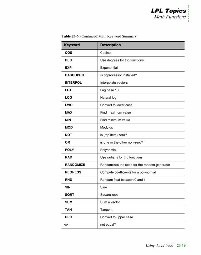
LPL TopicsMath Functions
Using the LI-6400 23-19
COS Cosine
DEG Use degrees for trig functions
EXP Exponential
HASCOPRO Is coprocessor installed?
INTERPOL Interpolate vectors
LGT Log base 10
LOG Natural log
LWC Convert to lower case
MAX Find maximum value
MIN Find minimum value
MOD Modulus
NOT is (top item) zero?
OR is one or the other non-zero?
POLY Polynomial
RAD Use radians for trig functions
RANDOMIZE Randomizes the seed for the random generator
REGRESS Compute coefficients for a polynomial
RND Random float between 0 and 1
SIN Sine
SQRT Square root
SUM Sum a vector
TAN Tangent
UPC Convert to upper case
<> not equal?
Table 23-6. (Continued)Math Keyword Summary
Keyword Description

LPL TopicsMath Functions
23-20 Using the LI-6400
23
The mathematical functions in LPL can operate not only on values, but alsoon collections of values. For example, consider the addition operator + asused in Figure 23-10 below
The + operator obviously does more than blindly add whatever is on the stacktogether. It checks to see what type of objects are sitting on the stack, and op-erates accordingly. Thus, we can not only add two numbers together, we canalso sum an array, add a constant to an array, or add two arrays together ele-ment by element, all with the keyword +.
In general, LPLÕs math functions can be classified as Two Object Transforms(e.g. +), or Single Object Transforms (e.g. ABS, absolute value).
Single Object TransformsSingle Object Transforms can operate on values, addresses of numeric vari-ables, or arrays, so there are a variety of combinations of things that can beon the stack when a Single Object Transform executes. We illustrate the pos-sible before and after stack status by the following shorthand:
:INT iArray[5] {1 2 3 4 5}:FLOAT floatVal 1.234 fArray[5] {10.1 11.1 12.1 13.1 14.1}
:FCT Main{/* Add two values 11.734 left on the stack */ 10.5 7 +
/* Add a constant to an array whose address is left on the stack. iArray = {6 7 8 9 10} */ iArray 5 +
/* Add Two Arrays. fArray address left on stack. fArray = {16.1 18.1 20.1 22.1 24.1} */ fArray iArray +
/* Add value to variable, by address. floatVal address left on stack,floatVal = 6.234 */ &floatVal 5 +
/* Compute the sum of an array. (6+7+8+9+10) = 30 is left the stack */ 0 iArray + }
Figure 23-10. Various uses of the + operator.

LPL TopicsMath Functions
Using the LI-6400 23-21
ÒNumÓ means DOUBLE or LONG. When a Single Object Transform oper-ates on numeric value a, the result will be either a DOUBLE or LONG pushedback onto the stack, depending on the keyword, and on the type (DOUBLEor LONG) of a. For example, the sine function (SIN) will always return aDOUBLE regardless of whether the argument is DOUBLE or LONG, whilethe sign change function (CHS) retains aÕs type.
ÒNAddrÓ means a numeric objectÕs address, such as the address of a CHAR,INT, LONG, DOUBLE, or FLOAT. ÒArrayÓ means the address of any array.When a Single Object Transform operates on NAddr c or Array d, the addressremains on the stack; the values of the variable or array may have changed,however.
When an Array is the object of the transform, each element of the array istransformed. If the array is a PTR array, its elements can potentially point atnon-numeric objects, such as function addresses, or other PTR arrays, so whathappens then? The rule is this: all pointer elements are tracked down (pointersto pointers to pointers, etc.), and if the final object is numeric, it is trans-formed. If not, and the transform requires ultimately a numeric value, then anÒIllegal ObjectÓ fatal error is generated.
Two Object TransformsTwo Object Transforms can operate on any combination of value, address ofnumeric variable, or array. The target of a Two Object Transform is the 2nditem on the stack, not the top item on the stack. The target can be a ÒNumÓ,ÒNAddrÓ, or an ÒArrayÓ, just like with Single Object Transforms. The object
Initial: Num aFinal: DOUBLE or LONG bor
Initial: NAddr cFinal: NAddr cor

LPL TopicsMath Functions
23-22 Using the LI-6400
23
on the top of the stack can also be any of these three items. In our referencesection shorthand, we express these possibilities by
Items in <> brackets, separated by a vertical bar (for example < a | b >) meansÒone or the other ofÓ. Thus, <a | b> means a or b. ÒNObjÓ means numericalobject: DOUBLE, LONG, or NAddr.
When a Two Object Transform operates on numeric target targetNum, the re-sult resultNum will be DOUBLE or LONG, depending on the keyword, anddepending on type (DOUBLE or LONG) of the original value.
When the target is an address targetVal or targetArray, the address remainson the stack, while the value(s) of the variable or array are subject to change.
When the top item on the stack is array d, but the target is not (targetVal ortargetNum), the transform is done using each element in d, with the targetValor targetNum holding the cumulative result. For example, you can sum Arrayd by the expression
0 d +
(Note that the reverse order (Òd 0 +Ó) would simply add 0 to each elementof d, accomplishing nothing). Table 23-7 summarizes the combinations
Initial: Num targetNum, <NObj c | Array d>Final: DOUBLE or LONG resultNumor
Initial: NAddr targetVal,<NObj c | Array d>Final: NAddr targetValor
Initial: Array targetArr, <NObj c | Array d>Final: Array targetArr
Table 23-7. Two Object Transform combinations
Target Object
Top-of-Stack Object
Num NAddr Array
Num Resulting value left on stack Transform performed multiple times, once for each array item. Resulting value left on stack.

LPL TopicsDisplay Control
Using the LI-6400 23-23
Trig FunctionsDEG and RAD specify the units of measure (degrees or radians) for trig func-tions. The default mode when an application runs is radians, unless the appli-cation is stack sharing (STKSHARE) with itÕs parent.
Display ControlLPL provides several tools for controlling the display. This section deals onlywith text; graphical applications are discussed in Graphics on page 23-56.
NAddr Target address left on stack. Transform performed multiple times, once for each array item. Target address left on stack.
Array Each element of the array is trans-formed using the top-of-stack value. Target address left on stack
Transform is performed on (and only on) corresponding items between the arrays. Target address left on the stack.
Table 23-7. Two Object Transform combinations
Target Object
Top-of-Stack Object
Num NAddr Array
Table 23-8. Keywords for controlling the display.
Keyword Description
BLKATTR Sets attribute in a specified rectangle (window coords)
CLEAR Clears text and attribute in current window
CLREOL Clears from cursor location to edge of current window
DISPHEIGHT Height (chars) of display
DISPWIDTH Width (chars) of display
GETDISP Gets display text, attribute, and window info
GETTEXT Gets text from a rectangle, (display coords).
GETWINDOW Get current window info (rectangle, cursor, etc.)
MOVETEXT Move a rectangle to a new location (lcd coords)
POSXY Positions the cursor (window coords).

LPL TopicsDisplay Control
23-24 Using the LI-6400
23
Display SizeSince LPL is platform independent, there is no fixed display size assumed.Therefore, the keywords DISPHEIGHT and DISPWIDTH will return theheight (in rows) and width (in characters) of the display (Figure 23-11).
Text WindowsLPL supports windowing the display. A text window is simply a rectangle onthe display in which text operations are confined. There are two types of units
PUTDISP Restores window, text, and attribute
PUTTEXT Puts text into a rectangle, (display coords)
PUTWINDOW Set current window info.
SCRLOCK Locks/unlocks vertical scrolling
SETATTR Sets attribute for subsequent printing
SETCURSOR Sets cursor type
WINDOW Establish a window (display coords)
Table 23-8. (Continued)Keywords for controlling the display.
Keyword Description
Hello, worldThis is a message
That is all...DISPWIDTH chars wide
DISPHEIGHTrows high
Figure 23-11. Illustration of DISPHEIGHT and DISPWIDTH.

LPL TopicsDisplay Control
Using the LI-6400 23-25
of measure used: display units(absolute) and window units(relatve)(Figure 23-12).
The WINDOW keyword creates a window on the display; the window can beframed by a single or double line border with up to two labels on it, or no bor-der at all. Figure 23-13 illustrates.
Hello, world
Hello, world
Row 1, Col 1 Display units
Row 1, Col 1 Window Units Row 4, Col 13 Display Units
Figure 23-12. Text windows

LPL TopicsDisplay Control
23-26 Using the LI-6400
23
By default, all text windows scroll automatically when filled with text. How-ever, they can be made to not scroll, but start overwriting at the upper left cor-ner instead. The keyword SCRLOCK controls this feature.
Text and Cursor AttributesText can have any combination of 2 attributes besides normal: inverse andblinking. The keyword SETATTR sets the attribute for all subsequent print-ing to the display.
The cursor can be in one of three states: hidden, underline, or full height. Thekeyword SETCURSOR establishes the cursor type. Also, the cursor can bemoved to any location within the current window by the POSXY keyword.
The keyword GETWINDOW loads the current window status, including at-tribute and cursor information, into an array. ItÕs counterpart, PUTWIN-DOW, will immediately implement a windowÕs scaling, attribute, and cursorlocation. Figure 23-15 creates two windows with differing attributes, thenswitches between them as it prints what you type.
:FCT Main{
CLEAR3 2 20 5 2 1 "Win1" 5 "Hello" WINDOW"This is in window 1" PRINT
15 4 35 8 1 3 "Win2" WINDOW"This is in window 2" PRINT
GETKEY /* Set window back to full display, borderless */1 1 DISPHEIGHT DISPWIDTH 0 WINDOW
}
Figure 23-13. Illustration of WINDOW keyword., with resulting display
This is in window 1
Win1
Hello This is in window 2Win2

LPL TopicsDisplay Control
Using the LI-6400 23-27
If you run the program illustrated in Figure 23-14 and type Òabcdefghijklm-nopÓ, it will appear as shown above, with every character going into alternat-ing windows. (The inverted square in the left hand window is the full cellcursor for that window.)
:INT w1[8] { } /* Holds attributes for window 1 * /
w2[8] { } /* Holds attributes for window 2 */:PTR activeWindow 0:FCT Main{
0 :INT flopCLEAR"Type something (<esc> quits)" PRINT
/* Make window 1. */1 3 20 7 2 WINDOW
/* Normal.*/0 SETATTR
/* Full height cursor.*/2 SETCURSOR
/* Save attributes for window 1 */w1 GETWINDOW
/* Set normal attrib for border. */0 SETATTR
/* Make window 2.*/22 3 40 7 2 WINDOW
/* Inverse. */1 SETATTR
/* No cursor.*/0 SETCURSOR
/* Save attributes for window 2.*/w2 GETWINDOW
LOOPGETKEY :INT kk 0x1b == BREAKIF&flop NOT VAL IF
w1 &activeWIndow =ELSE
w2 &activeWindow =THENactiveWindow PUTWINDOWk "%c" PRINTactiveWindow GETWINDOW
ENDLOOP0 SETATTR1 SETCURSOR1 1 DISPWIDTH DISPHEIGHT 0 WINDOW
}
Type something (<esc> quits)
acegikmo bdfhjlnp
Figure 23-14. Window switching example. Every other character typed goes into the left window, and the othercharacters go into the right window.

LPL TopicsDisplay Control
23-28 Using the LI-6400
23
Manipulating TextThe keyword CLEAR removes the text from the current text window, andsets the display attribute for the entire window to the current value. The key-word CLREOL clears the text and sets the display attribute for a line of char-acters extending from the current cursor location to the right edge of thecurrent window.
The attribute for a rectangle within the active window can be changed withoutchanging the text by the keyword BLKATTR.
MOVETEXT will copy a rectangle of text within the active window to anoth-er location, also within the active window.
The keyword pair GETTEXT and PUTTEXT are used to copy text betweenthe display (ignoring any windows) and an LPL CHAR array or PATH. At-tribute is ignored, although PUTTEXT can be made to impose an attribute onthe destination rectangle.
Frequently, it is desired to save the contents of the display beneath a window,so that when the window is removed, the display can be returned to the wayit was before. GETDISP and PUTDISP accomplish this easily. It is impor-tant to understand the differences between GETDISP/PUTDISP and GET-TEXT/PUTTEXT: The _DISP functions deal with text and attributeinformation, while the _TEXT functions deal just with text. Also, the usertakes care of the source or destination space for the _TEXT functions, whileGETDISP allocates space, and PUTDISP disposes of it. Therefore, GET-DISP and PUTDISP should always occur in pairs, with GETDISP first, andyou cannot PUTDISP twice using the same allocated space.

LPL TopicsKeyboard Control
Using the LI-6400 23-29
Keyboard ControlIn LPL, the keyboard can be the source for or destination of generalized dataflow, as described in I/O Programming on page 23-39. There are severalLPL keywords that pertain to the keyboard itself, and these are described inthis section.
Keyboard BehaviorWhen you press a key on the LI-6400, there may or may not be a beep (con-trolled by KBDCLICK - default is no beep). If you hold the key down, therewill be a slight delay (controlled by KBDDELAY - default 500 ms) followedby regular repetition (time interval controlled by KBDREPEAT - default 50ms).
Keyboard CodesKeys are identified in LPL by a 2 byte integer value. If the high byte is zero,then the key is an ascii key, and the low byte is the value. Thus, pressing thekey A will generate a key code of 97 (hex 61), while shift A generates 65 (hex41). If a non-ascii key is pressed, such as a cursor control key, or a functionkey, then the high byte is non-zero and contains the identifier for that key(Table 23-11 on page 30). The low byte (Table 23-12 on page 23-31) con-tains modifier key information (the state of the shift and ctrl keys). The file“/Sys/Lib/StdKeys” provides some LPL names for some non-ascii keys.
Table 23-9. Keyboard Control Keyword Summary
Keyword Description
BEEP Run the beeper for a period of time
GETKEY Get the next keystroke
KBDCLICK Enable/Disable keyboard sound for each key-stroke
KBDDELAY Set the delay time for the keyboard (time before repeats)
KBDREPEAT Set the key repeat frequency for the keyboard
NEXTKEY What key is available (-1 if none)
UNGETKEY Put back a keystroke

LPL TopicsKeyboard Control
23-30 Using the LI-6400
23
Note that not all keys supported by LPL are found on any specific platformÕskeyboard.
Table 23-10. Example Key codes
Key Stroke Key Code
x 0x0078
ctrl x 0x0018
pgup 0x2100
shift pgup 0x2102
Table 23-11. Non Ascii Key Codes: High Byte
The Key Variable
NameaHigh Byte
The Key Variable Name
High Byte
labels _Labels 0x12 f1 _F1 0x60
home _Home 0x24 f2 _F2 0x61
end _End 0x23 f3 _F3 0x62
pgup _PgUp 0x21 f4 _F4 0x63
pgdn _PgDn 0x22 f5 _F5 0x64
_UpArrow 0x26 f6 0x65
¯ _DnArrow 0x28 f7 0x66
¬ _LeftArrow 0x25 f8 0x67
® _RightArrow 0x27 f9 0x68
¬ _Back 0x08 f10 0x69
escape _Esc 0x1b f11 0x6a
enter _Enter 0x0d f12 0x6b
ins 0x2d f13 0x6c
del 0x2e f14 0x6d

LPL TopicsClock
Using the LI-6400 23-31
ClockLPL supports a real time clock.
haltb 0x1d f15 0x6e
a. DeÞned in the Þle /Sys/Lib/StdKeysb. The halt key can also be generated by ctrl escape
Table 23-11. (Continued) Non Ascii Key Codes: High Byte
The Key Variable
NameaHigh Byte
The Key Variable Name
High Byte
Table 23-12. Non Ascii Key Codes: Low Byte
Bits 2 thru 7 Bit 1 Bit 0
unused Control Shift
Table 23-13. Clock Keyword Summary
Keyboard Description
CTIME Convert seconds, print time and date in formatted string.
DATE Convert seconds to year, month, day
DAYOFWK Convert seconds to day of week
DAYOFYR Convert seconds to Julian day of year
GETMS Get ms since power on
GETTDS Get current date and time in seconds
SECS2TD Convert seconds to time and date info
SETTDS Set current date and time using seconds
TD2SECS Convert time and date info to seconds
TIME Convert seconds to hour, minute, second

LPL TopicsClock
23-32 Using the LI-6400
23
Real TimeTime in LPL is measured from some base time that is platform specific. In theLI-6400, the base time is 1 Jan 1989.
A quick way to find the time base for any particular platform is the LPL se-quence
0 CTIME
This will display the time and date corresponding to 0 time. Since the time iscontained in a LONG, each platform has an upper limit of dates it can handle,which can be determined by
-1 CTIME
The current date and time (in seconds since the base time) is obtained byGETTDS, and set by SETTDS.
LPL provides several tools for doing time conversions. DATE converts sec-onds since the base time to day, month, and year, while TIME extracts thehours, minutes, and seconds. SECS2TD converts seconds into date and time,while TD2SECS goes the other way. DAYOFWK and DAYOFYR convertsseconds to day of the week and day of the year, while CTIME converts sec-onds to a readable date string.
Time since power onFor timing with a higher resolution than seconds, GETMS will return thetime in milliseconds since power on or midnight, depending upon the plat-form.
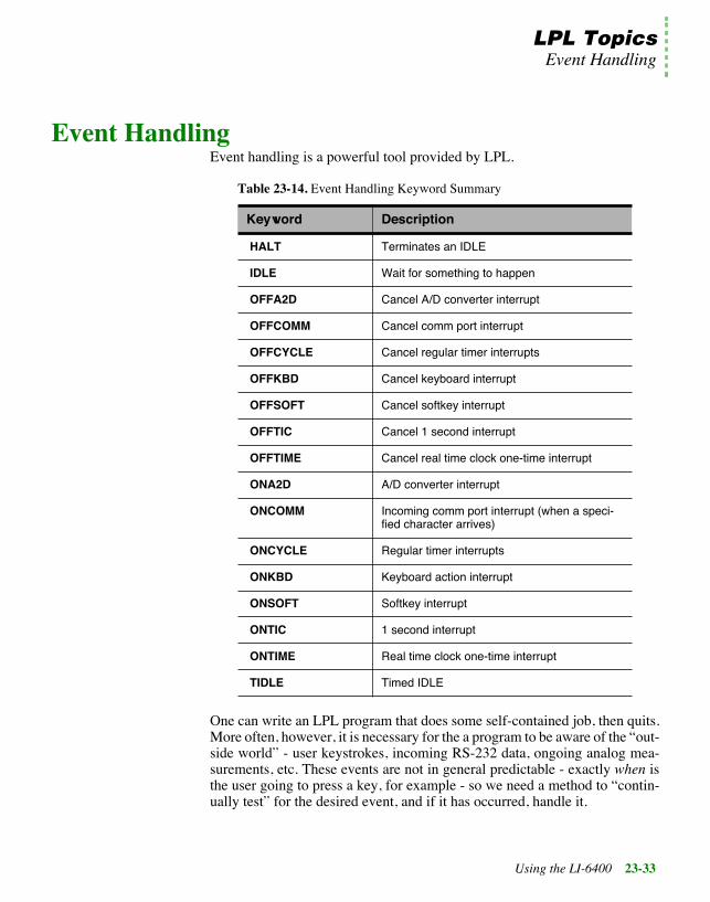
LPL TopicsEvent Handling
Using the LI-6400 23-33
Event HandlingEvent handling is a powerful tool provided by LPL.
One can write an LPL program that does some self-contained job, then quits.More often, however, it is necessary for the a program to be aware of the Òout-side worldÓ - user keystrokes, incoming RS-232 data, ongoing analog mea-surements, etc. These events are not in general predictable - exactly when isthe user going to press a key, for example - so we need a method to Òcontin-ually testÓ for the desired event, and if it has occurred, handle it.
Table 23-14. Event Handling Keyword Summary
Keyword Description
HALT Terminates an IDLE
IDLE Wait for something to happen
OFFA2D Cancel A/D converter interrupt
OFFCOMM Cancel comm port interrupt
OFFCYCLE Cancel regular timer interrupts
OFFKBD Cancel keyboard interrupt
OFFSOFT Cancel softkey interrupt
OFFTIC Cancel 1 second interrupt
OFFTIME Cancel real time clock one-time interrupt
ONA2D A/D converter interrupt
ONCOMM Incoming comm port interrupt (when a speci-fied character arrives)
ONCYCLE Regular timer interrupts
ONKBD Keyboard action interrupt
ONSOFT Softkey interrupt
ONTIC 1 second interrupt
ONTIME Real time clock one-time interrupt
TIDLE Timed IDLE

LPL TopicsEvent Handling
23-34 Using the LI-6400
23
Figure 23-15 illustrates (in Òpseudo-LPLÓ) how we might structure an LPLprogram to handle three types of events. Essentially, we sit in a tight loopwaiting for something to happen, and when it does, we deal with it. The func-tion HandleKeys, for example, would have to get the keystroke, and processit.
In order for this outline to work as an LPL program, weÕd have to fill in theroutines such as ClockReady?, to signal us at desired times or time intervals.
Fortunately, LPL hides much of this work from the programmer. It turns outthat to actually implement the outline in Figure 23-15, one only needs to a)register the functions to be called, and b) write those functions. Figure 23-16illustrates how this actually looks in LPL.
We register the functions to be called using the ON... LPL keywords.
:FCT EventLoop{
LOOPKeysReady? IF HandleKeys THENClockReady? IF HandleClock THENA/DReady? IF HandleA/D THEN...
ENDLOOP}KeysReady? {...}ClockReady? {...}A/DReady? {...}
HandleKeys { GETKEY ... }HandleClock { ... }HandleA/D { ... }
Figure 23-15. Illustration of the hard way to detect events
:FCT Main{
&HandleKeys ONKBD&HandleClock ONTIC&HandleA/D 1 ONA2D
IDLE}HandleKeys { GETKEY ... }HandleClock {...}HandleA/D {...}
Figure 23-16. Programming for events in LPL.

LPL TopicsEvent Handling
Using the LI-6400 23-35
ONKBD, for example, is for keyboard events. The handling functions are thesame as before in Figure 23-15. But notice that the entire event loop is nowcollapsed into the LPL keyword IDLE.
IDLE is just what it sounds like - the LPL program is idle. The operating sys-tem, however, is performing the tight loop checking for events. Whenever itfinds one for which we had registered a function, it calls that function for us.
LPL can handle a number of events (Table 23-15) in the manner outlined bythe listing in Figure 23-16.
To illustrate, consider the AutoProgram “Remote Control”, whose listing isshown in Figure 23-17.
Table 23-15. Events Supported by LPL
Event KeyWord
User presses any key on the keyboard ONKBD
User presses a function key ONSOFT
A certain time and date arrives (alarm clock) ONTIME
1 second intervals ONTIC
User defined intervals ONCYCLE
A/D Readings are ready ONA2D
A certain characterÕs arrival in the Comm port ONCOMM

LPL TopicsEvent Handling
23-36 Using the LI-6400
23
/*
Remote
970506 - Remote control autoprogram*/
:CHAR progName[] "REMOTE"
:PTR buff 0
:FCT main{
progName LPSetNameprogName "\f%s" PRINT
/* Configure the comm port*/"9600 8 1 n" COMMCONFIG
/* Open a data comm queue*/1000 OPEN_QUE IF RETURN THEN&buff =
/* Set up incoming data capture*/
COMM buff XFER 10 &GotIt ONCOMM
LPPrep
LOOP10000 LPMeasurelpAbort BREAKIF
ENDLOOP
/* Cleanup*/LPCleanupbuff CLOSEOFFCOMM
}
/* Gets called on receipt of line feed*/:CHAR line[500] "":FCTGotIt {
line 0 SETREADYline "%(.)c\n" buff ENTER DROPline COMPILE NOT IF
:PTR fct fct &fct FREE
THEN}
Figure 23-17. Listing of the AutoProgram “Remote Control”. The program sits endlessly in New Measurementsmode (LPMeasure), and incoming data from the comm port is collected in a buffer (COMM buff XFER). Ev-ery time a line feed is received, however, that data is compiled and executed (FCT GotIt). This allows a re-mote device to control the LI-6400. The sequence 10 &GotIt ONCOMM sets this up.

LPL TopicsThe Function Keys
Using the LI-6400 23-37
The Function KeysThe function keys provide a valuable interface tool, in that the options opento a user at any given time can appear on the display as key labels.
Even though the specific platform on which LPL is installed has a fixed num-ber of physical function keys (the LI-6400 has 5, for example), you can defineany number of function keys in LPL; the user can only see them in groups of5 (or whatever) at a time, but the labels key on the keyboard (or the equiva-lent) will change the displayed group. Groups can also be selected by pro-gram.
The function key tools described in this section work during IDLE (SeeÒEvent HandlingÓ on page 33). The strategy is to define how many functionkeys you want to ÒcreateÓ (MAKESOFT), then what each keyÕs label andfunction is (ONSOFT). During IDLE, the user can scroll through the keys (ifthere are too many to show at one time) using the labels key, and if he pressesone, the function happens automatically. OFFSOFT and FREESOFT dis-able and dispose of function key definitions. Figure 23-18 illustrates.
Table 23-16. Function Key Keyword Summary
Keyword Description
MAKESOFT Make a softkey structure
FREESOFT Free a softkey structure
HIDESOFT Hide softkey labels
SHOWSOFT Show softkey labels
SOFTSETM Set current menu level
SOFTGETM Get current menu level
SOFTWIDE How many softkeys can be shown at once?
GLOBALKEYS How should softkeys behave across nested IDLEs?

LPL TopicsThe Function Keys
23-38 Using the LI-6400
23
There are some other options with function keys. For example, should the la-bels appear all the time, or just when the user presses the labels key? Shouldthe current level of function keys be displayed in the lower left hand cornerof the display? Both of these are controlled by parameters in the call toMAKESOFT.
Another question is this: what happens to the function key definitions whilea function key is being processed (that is, while the function associated witha key is being executed)? Do the key labels stay visible? Should the functionkeyÕs definition be allowed to change? If another IDLE is encountered, do theold key definitions stay active? When the IDLE is done, do the old key defi-nitions get restored? All of this is controlled by one flag set with the keywordGLOBALKEYS.
:FCT Main{
/* Illustrate use of function keys*/
CLEAR
0 ' ' 1 2 0 5 MAKESOFT/* 0 - plain text for label
delimiter ' ' - the delimiter is a space 1 - inverse labels 2 - labels 2 lines high 0 - donÕt save background beneath
the labels 5 - total of 5 function keys
allowed*/
/* Fct Key 1 */"PRINT TIME" &PrintTime 1 ONSOFT
/* Fct Key 2 */"PRINT DATE" &PrintDate 2 ONSOFT
/* Fct Key 3 */"PRINT Ctime" &PrintCTime 3 ONSOFT
/* Fct Key 5 */" quit" &Quit 5 ONSOFT SHOWSOFT
IDLE
FREESOFT
}
/* When FctKey 1 pressed */PrintTime {
1 1 POSXY GETTDS TIME "Time is %2d:%2d:%2d"
PRINT}
/* When Fct Key 2 pressed */PrintDate{
1 2 POSXYGETTDS DATE "Year: %d Month:%d
Day:%d" PRINT}
/* When Fct Key 3 pressed */PrintCTime{
1 3 POSXYGETTDS CTIME
}/* When Fct Key 5 pressed */Quit { HALT }
Figure 23-18. Defining function keys

LPL TopicsI/O Programming
Using the LI-6400 23-39
¥ GLOBALKEYS on:Function key definitions remain active and labels stay visible while functionkeys are serviced, and while subsequent IDLEs are performed. Function keyscan be redefined without exiting the IDLE.
¥ GLOBALKEYS off:While a function key is serviced, the labels disappear, and all function keydefinitions are ÒforgottenÓ. When the service is done, the definitions are re-stored. This means that if you want nested IDLEs with new function key def-initions, you must do a new MAKESOFT. But when the child IDLE is done,the old key definitions are automatically restored. When GLOBALKEYS isoff, you cannot change a function key definition (label or function) withoutexiting the IDLE.
I/O ProgrammingThe ability to move information to and from devices is critical to any com-puter, and LPL provides an abundance of tools for doing that task.
Table 23-17. I/O Keyword Summary
Keyword Description
BENTER Binary enter from a path
BPRINT Binary print to a path
CLOSE Close any path
CONVERTIN Set incoming (writing to) path filter(s)
CONVERTOUT Set outgoing (reading from) path filter(s)
ENTER Read formatted or unformatted data from a path
GETCH Get a byte from a path
GETCONVERTIN Get current incoming filters
GETCONVERTOUT Get current outgoing filters
GETDFCIN Get current default file convertin
GETDFCOUT Get current default file convertout
IOCLEAR Clear path error
IOERR Get latest path error

LPL TopicsI/O Programming
23-40 Using the LI-6400
23
ISEMPTY Is the path empty
OPEN_BUFF Open a path to an expandable memory buffer
OPEN_CHARS Open a path to a character array
OPEN_COMM Open a path to the comm port
OPEN_FILE Open a path to a file
OPEN_FILE_ASK Open a path to a file, with handy user front end.
OPEN_KBD Open a path to the keyboard.
OPEN_LCD Open a path to the display
OPEN_QUE Open a path to a circular queue
PATHSTAT Get path status
PRINT Send formatted or unformatted data to a path
PUTCH Write a byte to a path
RESET Set fill and empty pointers to 0.
RESETDFC Reset (to platform default) default file convert in and out
SEARCH Search a path for the occurrence of something
SETDFCIN Set default file convertin
SETDFCOUT Set default file convertout
SETEMPTY Set empty (reading) pointer for a path
SETFILL Set fill (writing) pointer for a path
UNGETCH Character put back function for a path
XFER Send data from one path to another
Table 23-17. I/O Keyword Summary
Keyword Description

LPL TopicsI/O Programming
Using the LI-6400 23-41
PathsWe have seen how PRINT can display information on the display, and EN-TER can retrieve information from the keyboard. This section will extendyour appreciation for PRINT and ENTER, because we can use these sametools to deal with files, the comm port, buffers in memory, and sometimeseven the keyboard.
The unifying concept in all of this is the notion of a Path, which can bethought of as a Òdata tubeÓ. PRINT puts data into the tube, ENTER takes dataout of the tube, and we use PRINT and ENTER without being overly con-cerned about where the tube, or Path, leads. Thus, PRINT and ENTER con-cern themselves with the Path, while the operating system takes care of all themessy details involved with the various devices or memory that are at the oth-er end of the Path. LPL supports Paths to a variety of devices (Table 23-18).When an application is launched, four standard paths are provided, and areaccessible by the keywords LCD, COMM, ARGS, and KBD. Alternate pathsto these devices, or paths to other devices are opened by the various OPEN_keywords shown in Table 23-18.
A simple example of using Paths is shown in Figure 23-19, which writes aline of text to a file. Files are treated more thoroughly in the section File Sys-tem on page 23-46.
Table 23-18. Paths Supported by LPL
Device Created by Standard Path Name
Display OPEN_LCD LCD
Keyboard OPEN_KBD KBD
Comm Port OPEN_COMM COMM
Expandable memory buffer
OPEN_BUFF -
Circular memory queue OPEN_QUE -
CHAR Array OPEN_CHARS -
File OPEN_FILEOPEN_FILE_ASK
-

LPL TopicsI/O Programming
23-42 Using the LI-6400
23
Path RegistersEvery path has associated with it four status registers (Table 23-19). TheSETFILL and SETEMPTY keywords allow direct manipulation of the filland empty registers, whose present value can be determined by PATHSTAT.For example, to re-read a file from the beginning, one would set the emptyregister to 0 (the start of the file). Some operations adjust the registers implic-itly; PUTCH adds a character to the fill location, and updates the register,while GETCH takes a character from the empty location, updating the regis-ter.:
Path FiltersA very powerful feature of paths is the character filtering capability that theyhave. Filters can be independently enabled for reading data from a path, andfor writing data to a path. Table 23-20 indicates the filters available for LPLpaths.
Table 23-19. PATH Status Registers
Name Description
TYPE Describes what the path is pointing to (Table 24-29 on page 24-60).
SIZE Number of bytes
EMPTY Location of next byte of outgoing data
FILL Location of next incoming byteÕs destination.
:FCT main{
Open file "/user/MyFile" for writing."w" "/User/MyFile" OPEN_FILE IF RETURN THEN:PTR file
"This is a message." file PRINT
Close the path.file CLOSE
}
Figure 23-19. Accessing a file with a path.

LPL TopicsI/O Programming
Using the LI-6400 23-43
Note that filters can be chained together in any sequence. The keywordsCONVERTIN and CONVERTOUT define the filtering (if any) for data in-flow and outflow for any path. GETCONVERTIN and GETCON-VERTOUT will return the current filter sequence for any path.
Table 23-20. Path Filters
Code Convert From Convert To
e <cr>, <lf>, or <cr><lf> <lf>
E <cr>, <lf>, or <cr><lf> <cr><lf>
n <cr>, <lf>, or <cr><lf> <cr>
tn n spaces (n=0...16) tab
Tn tab n spaces (n=0...16)
s \xdd or \ddd ascii character
S nonprintable characters \xdd
k Byte pairs If 1st byte is null it is stripped; otherwise, \k sequence out-put.
K Does reverse of ÒkÓ filter: bytes are padded with nulls, except for the \k se-quence.
Byte Pairs
cxy character x character y
Cxy 1 or more contiguous characters x character y

LPL TopicsI/O Programming
23-44 Using the LI-6400
23
will produce the lines
123456781234567812345678abc def ghi
Transferring DataThere are several tools for moving data into or out of paths. GETCH andPUTCH do a byte at a time. PRINT and ENTER move formatted ascii databetween paths and LPL variables. BPRINT and BENTER move the valuesof LPL variables in binary form to and from paths. XFER transfers data fromone path to another, and (depending on what type of paths are involved) cando it simultaneously with LPL program execution. For example, with an over-lapped XFER, a file can be sent out the comm port at the same time that mea-surements are being taken. As an example of data transfers, considerFigure 23-21, a simple terminal emulator program.
:FCT Main{
Open a path to the display.OPEN_LCD IF RETURN THEN:PTR disp
Define 8 column tabs."T8" disp CONVERTIN
Send some data with imbedded tabs to ÕdispÕ."123456781234567812345678\nabc\tdef\tghi" disp PRINT
GETKEY DROP Close the path ÕdispÕ.
disp CLOSE
Figure 23-20. Simple Filter Example

LPL TopicsI/O Programming
Using the LI-6400 23-45
Formatted ASCII I/OFormatted output includes right and left justification, number of significantdigits, leading and trailing spaces or zeros, rounding, delimiters between ar-ray elements, and other features. These features are controlled by the formatstring expected by PRINT. Formatted input, controlled by the format stringexpected by ENTER, define the rules by which the numbers and strings areextracted from input data.
I/O ErrorsThe keyword IOERR returns the error (if any) that has most recently hap-pened for any path. Possible errors are given in Table 23-21. The keywordIOCLEAR resets the error number for a path to 0 (no error).
Table 23-21. I/O Error codes
Error Number Condition
0 No error
1 Attempting to write to a full path
2 Attempting to read from an empty path
3 Attempting to move a pointer outside of a pathÕs limits
:FCT Main{
/* Incoming data -> display.*/COMM LCD XFER
Typed chars -> comm port.KBD COMM XFER &Keys ONKBD
IDLE}Keys {
GETKEY :INT k/* Quit if <esc> pressed.*/
k 0x1b == IF HALT THEN /* "Echo" the character to the display.*/
k "%c" PRINT }
Figure 23-21. Simple terminal emulator

LPL TopicsFile System
23-46 Using the LI-6400
23
File SystemThe LPL File System supports a hierarchical directory structure, and providesa number of controls for files, directories, and disks.
Table 23-22. File System Keywords
Keyword Description
DEVNAME Returns the hardware location of a disk
DIRALL Get list of all directories in the file system
DIRCURR Get current working directory
DIRERASE Erase a directory
DIRMAKE Make a directory
DIRSAVE Make sure file system is up to date
DIRSET Set current working directory
DSKFORMAT Format a disk
DSKISSWAP Is a disk off-line and available for swap space?
DSKOFFLINE Take a disk off-line
DSKONLINE Take a disk on-line
DSKPACK Defragment a disk
DSKSPACE How much space on a disk
FCOPY Copy a file
FERASE Erase a file
FGETTDS Get file time and date
FGETWP Get write protect status of a file or directory
FLIST Get a list of files and/or directories
FMERGE Merge path and file names into file specifier
FMOVE Move a file
FPARSE Parse file specifier into path and file names
FRENAME Rename a file

LPL TopicsFile System
Using the LI-6400 23-47
Hierarchical StructureThe LPL file system should be visualized as a tree: Tied to a common root areone or more directories. Within each directory there may be files and/or moredirectories.
An illustration of a file system containing three disks, named Dir A, Dir B,and Dir C is shown in Figure 23-22.
FSETTDS Set file time and date
FSETWP Write protect a file or directory
FSIZE Get file size
FTRASH Returns the trash location
FTYPE Determine if exists, or file, or directory
FUPDATE Update changed portion of a file
FWPICK Pick file from a list of possibilities
OPEN_FILE Open a a path to a file.
OPEN_FILE_ASK Open a path to a file, using Standard File Dialog box.
Table 23-22. File System Keywords
Keyword Description

LPL TopicsFile System
23-48 Using the LI-6400
23
Directory C contains 2 files and 1 directory, which in turn contains two direc-tories, the first of which has two files
Working With FilesBefore data can be read from or written to files, they must be opened(OPEN_FILE or OPEN_FILE_ASK). When a file is opened, a Path is cre-ated, and all data transfer operations take place through the path (I/O Pro-gramming on page 23-39). Files can be opened with various combinations ofattributes: write access, read access, and write-append. Am example programis shown in Figure 23-23.
The Root
Dir A
Dir B
Dir C
Dir A
Dir A
File 1File 2File 3
File 1File 2
File 1
File 1
File 1
File 2
File 2Dir ADir B
"/Dir C/Dir A/Dir A/File 2"
Figure 23-22. File system illustration.

LPL TopicsFile System
Using the LI-6400 23-49
Other file operations can occur on files and directories without opening them,such as those provided by the Filer (copying, moving, erasing, etc.). LPL pro-vides keywords to do those same operations from a running program(FCOPY, FMOVE, FERASE). File time stamp information can be read orset using FGETTDS and FSETTDS.
The Trash DirectoryWhen files are deleted via the Filer, they are moved to a Trash directory. Atrash directory will exist for each disk that has had at least one file removed.Please note that the Trash directory is a Filer implementation only - removinga file from a running LPL program by using the FERASE keyword does notmove the file to the Trash. If you wish to use the trash instead of FERASE,then use this code sequence:
fileName DUP FTRASH FMOVE
The LI-6400 File SystemOn the LI-6400 platform, the file system uses flash memory, and is part of ageneral file system structure that includes all hardware devices (the keyboard,comm port, A/D converter, digital ports, etc.). In general, you neednÕt be con-cerned with this underlying structure, except in one circumstance: transfer-
:FCT TestReadWrite{"w" "/user/testFile" OPEN_FILE NOT IF
:PTR file
"This is a test\n" file PRINT"This is the end of the test" file PRINT
file CLOSETHEN
"r" "/user/testFile" OPEN_FILE NOT IF:PTR source
LCD source XFER
source CLOSETHEN}
Figure 23-23. Example of programming file reading and writing. This func-tion writes two lines to a file, then copies the contents of the file to the dis-play.

LPL TopicsFile System
23-50 Using the LI-6400
23
ring disk images. The 6400-50 System Software installation disk programsuse this feature to install the /sys disk. To read or write a disk image, the diskmust be addressed at a lower level than normally, and to do this, one must useitÕs hardware name. The keyword DEVNAME returns the hardware namegiven a disk name. For example, the disk /user might be located at/dev/flashdisk1. It also might move around: anytime you defragment a disk (us-ing the Filer, or the key word DSKPACK), a disk will move to a differentflash disk, so our /user disk could move to /dev/flashdisk3, for example. If oneopens the ÒfileÓ /dev/flashdisk3 to read, one will be reading the binary imageof that disk, including directory information, file fragments, and everythingelse, valid or invalid, in sequence.
These underlying hardware names are the reason that on the LI-6400, one canhave multiple disks with the same name. This is not a good thing to do inten-tionally, of course, but it can be done.
Two devices in this hardware tree are /dev/parm0 and /dev/parm1, which are 8Kblocks of flash memory configured as single files. They are excluded fromview from the Filer (more precisely, they are excluded from being listed asdirectories from FLIST, the keyword that is used to get lists of files and/ordirectories), and are used to store calibration and configuration informationin a ÒsafeÓ place.

LPL TopicsMenus and Editors
Using the LI-6400 23-51
Menus and EditorsLPL provides some high level user interface tools for selecting an item froma list (a menu) and for entering numbers or text (an editor). Further, users cancustomize the behavior of either of these tool types.
Standard Menus and Editors
Standard MenuThe keyword STDMENU displays a list of items in the current text window,and allows the user to make a selection. Options available for STDMENU in-clude a menu bar (highlighted band that moves up and down with the cursor),what ascii keys cause exit, what non-ascii keys cause exit, and if/how to ad-just the cursor on exit.
Table 23-23. LPL Menu and Editor Keywords
Keyword Description
MESSBOX Put up a message in a window
STDLINE Single line edit
STDEDIT Multiple line edit
STDMENU Standard menu function
SETTARGET Set editor search target
GETTARGET Return current editor search target
EDOPEN Set up a custom editor
EDCLOSE Dispose of a custom editor
EDCTL Perform an editor function
EDSTAT Get some editor information
EDWRITE Custom edit function
EDKEY Custom edit function
FILER Access the Filer.
FEDIT Edit a file (< 64000 bytes)
FVIEW View a file (any size)

LPL TopicsMenus and Editors
23-52 Using the LI-6400
23
Figure 23-24 creates a window, and uses STDMENU to display the contentsof a CHAR array in that window as a menu with a menu bar. The user canscroll through the contents, then exit using escape or enter.
The and ¯ keys move the highlighted menu bar up and down. In general,the cursor control keys defined for the standard menu function are given inTable 5-2 on page 5-4.
What was selected? Something very important is missing in Figure 23-24: there is no way to tellwhat was selected. To do this, we must pass the STDMENU function a Pathinstead of a simple CHAR array, because STDMENU uses the Path statusregisters to tell us where the cursor was when the user exits. We fix this prob-lem in Figure 23-25 by making a Path to the menu items, then after STD-MENU is finished (if the user pressed enter) we read in the selected line.
:CHAR menuItems[] "This is item #1This is item #2and item #3and 4and 5and 6\nand 7\nand 8\nand lastly, 9"
:FCT Main{/* Make a window */
5 1 25 8 2 2 "My Menu" WINDOW
/* Use a menu bar, and exit on esc or enter */1 "" "\r" menuItems STDMENU DROP
/* Cleanup the display */1 1 DISPWIDTH DISPHEIGHT 0 WINDOWCLEAR
}
Figure 23-24. Programming with STDMENU.
My Menu
Print Find ReFind CANCEL SELECT
This is item #1This is item #2and item #3and 4and 5and 6

LPL TopicsMenus and Editors
Using the LI-6400 23-53
We can tell if the user pressed escape or enter by checking the return valueof STDMENU. We read the selected line using ENTER, since STDMENUleft the empty register of the Path at the last cursor location. What if the userhas scrolled to the right, and the cursor was not on the left column? We pre-vent this from being a problem by setting the line
3 "" "\r" menu STDMENU
The 3 indicates a menu bar, and also to snap the cursor to the left column onexit.
Single Line EditorThe keyword STDLINE creates a borderless window from the current cursorposition to the right edge of the current window, displays in this window theText object to be edited, and lets the user edit the object. escape or enter ter-minate STDLINE.
:CHAR menuItems[] "This is item #1This is item #2and item #3and 4and 5and 6\nand 7\nand 8\nand lastly, 9":FCT Main{
5 1 25 8 2 2 "My Menu" WINDOW
/* Open a path to the CHAR array.*/menuItems OPEN_CHARS IF RETURN THEN:PTR menu
/* Use menu bar, exit on esc or enter, move cursor to left. */3 "" "\r" menu STDMENU :INT k
1 1 DISPWIDTH DISPHEIGHT 0 WINDOWCLEAR
/* If user pressed enter...*/ k '\r' == IF
0 :CHAR line[80]/* Read the selected entry.*/
line "%(.)c" menu ENTER DROPline "You chose: '%s'" PRINTGETKEY DROP
THEN}
Figure 23-25. STDMENU example: knowing what was selected.

LPL TopicsMenus and Editors
23-54 Using the LI-6400
23
Multiple Line EditorThe keyword STDEDIT invokes the system editor for a Text object. If a filename is specified, the system editorÕs Exit Menu will be accessible.
FEDIT or FVIEW provide a quick way to invoke the system editor on a file.
Customized Editors and MenusThe keywords EDOPEN, EDCTL, EDWRITE, EDKEY, and EDCLOSEallow you to create menus and editors with customized behavior. Also, SET-TARGET, GETTARGET allow program control over searching for targetsin an editor or menu. The Display Editor in OPEN is an example of a custom-ized menu. This routine shows the makeup of OPENÕs display lines, and al-lows the user to edit them. An abbreviated listing of this routine is shown inFigure 23-27. Note the inclusion of the file “/Sys/Lib/CEDefs”, which containsuseful tools for these operations.
:CHAR fileName[80] "myData":FCT Main{
"Enter a file name:" PRINTfileName STDLINE IF
fileName "\nname is Õ%sÕ" PRINTELSE
"\nName not changed!" PRINTTHENGETKEY DROP
}
Figure 23-26. Using STDLINE.

LPL TopicsMenus and Editors
Using the LI-6400 23-55
/***********************
DisplayEditor (partial)
Called from OPEN
************************/:IFNDEF CERefresh
:INCLUDE "/sys/lib/CEDefs":ENDIF
:PTR menu 0 /* our data path */edPtr 0 /* custom data struct */
:FCT Main{/* Make a path for the menu contents */
1000 OPEN_BUFF IF RETURN THEN&menu =
/* Make a window. */1 1 DISPWIDTH DISPHEIGHT 2 2
"Display Editor" WINDOW
/* Fill the content path.*/menu DEBuildMenu
/* Create a custom menu structure.*/menu EDOPEN IF RETURN THEN&edPtr =
&DEKeys ONKBDDESoftKeys
/* Turn on the menu bar.*/edPtr CEToggleMenuBar
IDLE
ResetWindowedPtr EDCLOSEmenu CLOSE
}/* Write the initial contents of the menu to the path passed to this function. */
DEBuildMenu{
:PTR menu...
}
DEKeys{
GETKEY :INT k
k _Esc == IF DEQuitTest RETURN THEN
k 127 < IF /* is it ascii? */&k LWC DROP
/* If ÕaÕ thru ÕzÕ, jump to that format line.*/
k 'a' >= k 'z' <= AND IFedPtr CEHomeTogglek 'a' - 1 + workingFmtList
READY MIN edPtr CEJumpToLineedPtr CEToggleMenuBar
THENELSE
/* If itÕs non-ASCII, pass it through to EDKEY */
edPtr CEToggleMenuBark edPtr EDKEYedPtr CEToggleMenuBar
THEN}
DESoftKeys{
0 ' ' 1 1 0 10 MAKESOFT
/* WeÕll just illustrate Fct Key 1 */" Edit" &DEEditLine 1 ONSOFT...
SHOWSOFT}
Figure 23-27. Partial listing of OPENÕs Display Editor, which uses a custom editor based on EDOPEN.

LPL TopicsGraphics
23-56 Using the LI-6400
23
GraphicsLPL provides graphics tools for drawing lines, plotting points, etc. on a dis-play device.
Table 23-24. Graphics Keyword Summary
Keyword Description
ALPHA Show / hide text display
GBOX Clear / frame / fill a rectangle (user units)
GCLEAR Clear graphics window
GDRAW Graphics pen absolute draw (user units)
GETALPHA Is alpha visible?
GETGRAPH Is graph visible?
GHEIGHT Height of current graphics window
GICON Plot a 5x5 image centered at pen location (user units)
GIGET Copies a graphics image to a buffer (user units)
GINIT Initializes / Resets graphics
GIPUT Puts a graphics image on the display (user units)
GISIZE Gets required size of a graphics image (user units)
GLABEL Label in graphics mode at pen position
GLSIZE Determine height and width in pixels of a label
GMDGET Gets graphics drawing mode
GMODE Sets graphics drawing mode
GMOVE Graphics pen absolute move (user units)
GPGET Get a pixel (user units)
GPLOT Executes move/draw data stored in a structure.
GPPUT Put a pixel (user units)
GRAPH Show / hide graphics display
GRDRAW Graphics pen relative draw (user units)

LPL TopicsGraphics
Using the LI-6400 23-57
Graphics HardwareNote that the graphics display and the text display are conceptually different,and may in fact be physically different as well, depending upon the platform.On the LI-6400, the graphics and text displays use the same LCD display, butthis device has two separate modes of operation; text and graphics can beshown separately, or together. In the Macintosh implementation of LPL, thetext and graphics come out in two separate windows.
The keywords GRAPH and ALPHA turn on/off the graphics and text dis-plays. GETALPHA and GETGRAPH return the state of each display: on(visible) or off (not visible). On platforms where text and graphics share com-mon hardware, the ÒinteractionÓ between text and graphics images is set byGTMODE and sensed by GTMDGET, and can be any of the following: or,exclusive or, and and.
Note that on the display of the LI-6400, there is ÒinterferenceÓ between texthighlights (inverse and blinking) and graphics mode: text modes will not beshown when graphics mode is also on.
GRMOVE Graphics pen relative move (user units)
GSCALE Scale graphics area (user units)
GSCGET Gets current scaling (user units)
GSCROLL Enable/Disable auto scrolling
GSHIFT Shift a rectangular region (user units)
GTMDGET Gets graphics-text interaction mode
GTMODE Sets graphics-text interaction mode
GWHERE Gets current pen location (user units)
GWIDTH Width of current graphics window
GWIGET Get current graphics window (Display Pixels)
GWINDOW Define graphics window (Display Pixels)
Table 23-24. Graphics Keyword Summary
Keyword Description

LPL TopicsGraphics
23-58 Using the LI-6400
23
Windows and CoordinatesIn a graphics window, the smallest element is a pixel. The Pixel HardwareCoordinates (PHC) has pixel (0,0) as the lower left pixel in the physical dis-play window. In Pixel Window Coordinates (PWC), pixel (0,0) is the lowerleft pixel in the display window (a subset of the physical display). Finally,there are User Coordinates (UC), whereby the user can scale the current plot-ting window to any range of real numbers that is desired.
The keywords GHEIGHT and GWIDTH return the height and width of thecurrent graphics window. The default graphics window (at power on and afterthe reset function GINIT) is full size: it fills the physical graphics display. Thewindow can be reduced by the keyword GWINDOW, which specifies a newgraphics window and PWC coordinate system. To find the current graphicswindow, use GWIGET. To scale a graphics window to user coordinates, useGSCALE. Its counterpart, GSCGET returns the current scaling parameters.Figure 23-28 illustrates the use of some of these graphics key words for scal-ing.

LPL TopicsGraphics
Using the LI-6400 23-59
Drawing and LabellingSingle pixel access is available through GPGET and GPPUT. More useful,higher level routines are available, however. Figure 23-28 illustrated the fun-damentals of drawing in graphics mode when it draws the sine curves. Thebasis of drawing is a hypothetical graphics pen, whose location is set byGMOVE (go to a certain location without drawing) and GDRAW (draw fromthe present location to the given location). There are also a relative move and
:FLOAT scale[4] {0 1.1 360 -1.1}
:FCT Main{/* Reset the scaling. */
GINIT/* Turn off text, turn on graphics, clear the graphics display. */
1 GRAPH 0 ALPHAGCLEAR
/* Get the dimensions of the graphics display. */
GWIDTH :INT pixelsWideGHEIGHT :INT pixelsHigh
DEG/* Scale the plotting area.*/
scale GSCALE
/* Draw a sine curve */DrawACurve
/* New window in the lower left 1/3 of the display */
0 pixelsHigh 3 / pixelsWide 3 / 0
GWINDOW
/* Re-draw sine curve */DrawACurve
/* Admire the results */GETKEY1 ALPHA 0 GRAPH
}
DrawACurve{/* Frame the graphics window */
1 scale GBOX
0 :INT angle/* Move to 0, sin(0) */
0 0 GMOVE/* Draw a sine curve */
36 NLOOPangle DUP SIN GDRAW&angle 10 + DROP
ENDLOOP}
Figure 23-28. Graphics windows illustration, and the program m that generated it.

LPL TopicsGraphics
23-60 Using the LI-6400
23
draw functions GRMOVE and GRDRAW that move the pen relative to itscurrent location. The current pen location can be found with GWHERE.
GBOX is used to frame, fill, or clear a rectangle. GPLOT requires an arrayof X-Y coordinates, and it can either draw a line connecting them, or plot acharacter at each coordinate pair.
Labels and symbols can be done with GLABEL, which draws a string start-ing at the pen location, and GICON, which plots a 5x5 pixel image at the penlocation. GLORG specifies where the label is to be relative to the current penlocation (Figure 23-29). Thus, if GLORG is 8, the label will appear to the leftof the pen location, centered vertically. GLSIZE returns the height and widthof a label in pixels, which can be an aid to positioning it.
321
654
987
Graphics Label
Figure 23-29. GLORG locations for a graphics label relative to pen location.

LPL TopicsGraphics
Using the LI-6400 23-61
The program in Figure 23-30 produces a labelled cosine curve(Figure 23-31).
:FLOAT angle[50] { }cosine[50] { }fromAngle 0toAngle 720
:INT graphBox[4] { 20 60 200 7 }
:FCT Main{
GINIT1 GRAPH 0 ALPHADEGGCLEAR
/* Generate some data */FillArrays
/* Draw the axes, and scale */DoAxes
/* Draw the curve */0 angle cosine GPLOT
/* Plot the points */'+' angle cosine GPLOT
GETKEY 0 GRAPH 1 ALPHA}
DoAxes{/* This labelling is done while weÕre still in pixel coordinates */
20 4 GMOVE"0" GLABEL200 4 GMOVE"720" GLABEL100 4 GMOVE"DEGREES" GLABEL
2 7 GMOVE"-1" GLABEL2 60 GMOVE"+1" GLABEL
/* Make a box for plotting, and change to user coordinates */
graphBox GWINDOWfromAngle 1.1 toAngle -1.1 GSCALE
/* Draw axes lines */0 -1 GMOVE0 +1 GDRAW0 0 GMOVE720 0 GDRAW
}
/* This routine fills ÕangleÕ with angles, and ÕcosineÕ is filled with corresponding cosines */FillArrays{
angle SIZE :INT ntoAngle fromAngle - n / :FLOAT deltafromAngle :FLOAT x1 :INT in NLOOP
/* Store the angle */x angle i PICK =
/* Store the cosine */x COS cosine i PICK =&x delta + DROP&i 1 + DROP
ENDLOOP/* Make the arrays look full */
n angle SETREADYn cosine SETREADY
}
Figure 23-30. Labelling in graphics mode.

LPL TopicsGraphics
23-62 Using the LI-6400
23
Drawing ModesWhen lines and labels are being drawn in graphics mode, the drawing mode(set by GMODE) determines what happens as the new graphics informationoverwrites old graphics information. For example, where lines intersect,should the pixels be on or off. The possibilities are listed in Table 23-25.
The effects of the graphics drawing mode is illustrated in Figure 23-32.
Table 23-25. Graphics Drawing Modes
Mode Name Action
0 default Draw or erase without checking existing graphics state.
1 or
2 eor
3 and
4 not Invert, then Mode 0
Figure 23-31. Labelled cosine curve

LPL TopicsGraphics
Using the LI-6400 23-63
:INT rect1[] {0 30 40 8}add[] {1 0 1 0}rect2[] {10 50 30 10}mode1 0mode2 0
:PTR mode[] {"0 dflt" "1 OR" "2 EOR" "3 AND" "4 NOT"}
:FCT Main{
1 GRAPH 0 ALPHAGWIDTH 5 / :INT deltaadd delta * DROPGINIT GCLEAR1 :INT i5 NLOOP
mode i PICK DoBoxes&mode2 1 + DROP&i 1 +
ENDLOOP0 &mode2 = DROPGETKEY DROP0 GRAPH 1 ALPHA
}DoBoxes{
:PTR label
mode1 GMODE
/* Example 1 uses this */2 rect1 GBOX
/* Example 2 uses this *//* 1 rect2 GBOX */
mode2 GMODE
/* Example 1 uses this */1 rect2 GBOX
/* Example 2 uses this *//* 2 rect1 GBOX */
rect2 1 PICK VAL 30 GMOVElabel GLABEL
0 GMODErect2 1 PICK VAL 4 GMOVElabel GLABEL rect1 add + DROPrect2 add + DROP
}
Example 1: The solid rectangles and the lower labels are drawn first, using mode 0. The mode is changed to the indicated values, and the open rectangles and upper labels are drawn
Example 2: The open rectangles and the lower labels are drawn first, using mode 0. The mode is changed to the indicated values, and the solid rectangles and upper labels are drawn.
Figure 23-32. Illustration of drawing modes

LPL TopicsRS-232 Communications
23-64 Using the LI-6400
23
Graphics Image HandlingLPL provides some tools for handling graphics images. Images can be copiedfrom the display to a Path with GIGET, and restored to the display withGIPUT. The utility programs “/Sys/Utility/Graphics Capture” and “/Sys/Utility/Graph-ics Restore” use these keywords. The programs are discussed on page 21-16.
Graphics images can be moved around on the display by GSCROLL. Thekeyword GSHIFT determines the scrolling characteristics. This is the methodby which OPENÕs New Measurements strip chart mode works.
RS-232 CommunicationsLPL provides several tools for dealing with the Comm Port.
The utility program “/Sys/Utility/SETCOMM” (described on page 21-19) illus-trates the use of COMMSTATUS and COMMCONFIG. Its listing is shown inFigure 23-33.
Table 23-26. COMM Port Keyword Summary
Keyword Description
BLKREC Block receive
BLKSEND Block send
COMMBREAK Set Momentary break condition
COMMCONFIG Configure the comm port: data bits, stop bits, parity, soft-ware and hardware handshaking.
COMMLC Comm line control
COMMLS Comm line status
COMMSTATUS Print the comm configuration to a Path or CHAR array.
COMMUART Get uart status
FX Enter file exchange mode
ONCOMM Incoming comm port interrupt (when a specified charac-ter arrives)

LPL TopicsRS-232 Communications
Using the LI-6400 23-65
/* Set Comm port params*/
:INT commRect[] {2 2 38 4}
:FCTsetcomm{
0 :CHAR cline[40]
commRect GETDISP :PTR hold
commRect 2 1 "Baud Data Stop Parity" WINDOW
cline COMMSTATUS cline STDLINE IF cline COMMCONFIG
IF 1 "Bad Configuration!" MESSBOX THEN ELSE 1 "Config unchanged" MESSBOX THEN
hold PUTDISP}
Figure 23-33. Listing of the program SETCOMM.

LPL TopicsAnalog Measurements
23-66 Using the LI-6400
23
Analog MeasurementsAnalog measurements are meaningful only on platforms that have the hard-ware capability (an A/D convertor) to accomplish this task. However, all plat-forms support the LPL keywords, and may provide an interface for gettingmeasurements from another device. At any rate, LPL provides a lot of flexi-bility in its analog measurement capability.
Groups and ChannelsAt the heart of LPLÕs treatment of analog measurements are two concepts:group and channel.
A channel is a physical measurement channel, and corresponds at some pointto where a wire must be connected. Each channel has an address, starting with0, and the number of channels available is one of the three values obtained viaAINUM. Thus, if there are 24 channels, they are addressed as 0 thru 23.
A group, on the other hand, has no physical manifestation. A group is simply
Table 23-27. Analog Measurement Keyword Summary
Keyword Description
AINUM Returns the number of analog input channels, ground chan-nels, and maximum number of groups that can be defined.
AIOPEN Create an internal A/D structure.
AICLOSE Dispose of an A/D structure.
AIGDEF Define a group.
AICDEF Define a channel in a group.
AIPREP Build the action table based on the defined groups and channels.
AISTART Start or resume the A/D.
AISTOP Stop the A/D.
AIREADY Are readings available?
AIGET Get a reading
AITGET Get a reading with the time stamp
AIFREE Dispose of the action table.

LPL TopicsAnalog Measurements
Using the LI-6400 23-67
a collection of channels that are to be measured in the same way. That is,groups define how channels are measured, as all channels in a group are mea-sured the same way, in terms of frequency, number of samples, etc. Groupsare identified by number, starting with 0. The number of possible groups (his-torically 5) is also obtained via AINUM.
To illustrate groups and channels, consider the main LI-6400 application,OPEN. The LI-6400 has a four gas analyzer signals (two CO2 and two H2O),and about 12 other sensors, such a light sensors, thermistors, etc. We wantreadings for all of these sensors every, say, 1 second, and we want those read-ings to be an average over the prior 1 second. But, the gas analyzer signalsrequire higher resolution and move averaging to smooth the noise than theother sensors. We still want 1 second readings, but they should reflect a lotmore sub-readings than the other sensors. How do we accomplish this?
We could define two measurement groups: Group 1 could sample at 8 Hz andprovides a new reading (the average of those 8 samples) every 1 second.Group 2 could sample at 20 Hz, and provides a new reading every 1 second,but that new reading would be the average over the last 4 seconds, for exam-ple, to help smooth the noise. Having defined the groups, we then can identifythe channels that are to be included in each group.
Note that in LPLÕs scheme of things, the same channel can be included inmultiple groups. One could, for example, measure a thermocouple in two dif-ferent ways by including it in two different groups. One group might providehigh speed sampling, and the other longer term averaging.
Setting It UpAnalog measurements involve a lot of behind-the-scenes stuff that the oper-ating system takes care of, and you the programmer donÕt need to worry about(very much). However, there is a right way and a wrong way to get thingsdone, so a few simple rules need to be followed.
The first step in making analog measurements is to tell the operating systemto make some work space for itself. This is done with AIOPEN, which re-turns an address that you must keep track of. The best method is to use a glo-bal pointer. It is in this internal structure that the operating system will keeptrack of our group and channel definitions. Looking ahead, when we are donewith a particular set of definitions, we should get rid of them via AICLOSE.
The next step is to define our groups (with AIGDEF) and then channels (withAICDEF). Once this is done, we tell the operating system to ÒcompileÓ ourdesires into an Òaction tableÓ, using AIPREP.

LPL TopicsAnalog Measurements
23-68 Using the LI-6400
23
Now we are ready for measurements. AISTART will start our measurements.If for some reason we want to suspend A/D activity, we use AISTOP. To re-sume it again, use AISTART.
Easy, right? Well, weÕve glossed over some important details: Where do themeasurements go? How do you get hold of them to display them, or do com-putations?
Where Do They Go?When a channel is defined, the following information must be passed to theAICDEF function:
¥ The address of the internal A/D structureThis is typically referenced via a pointer from a prior AIOPEN.
¥ The signal channelReferred to by number (0 to 23).
¥ The group to which this channel definition belongsReferred to by number (0 to 5). Must have already been defined via AIGDEF.
¥ The reference (e.g. ground) channelReferred to by number (0É7).
¥ The rangeThis is not currently used, but still must be present. Just say 0.
¥ The address of the destination variableThis must be a FLOAT or a FLOAT array.
Thus, every channel gets linked to a FLOAT variable that you must maintain.(Make sure the destination variable will always exist - using a local variablefor this is a bad idea, for example.)
When Do They Get There?Now that we know where to find our measurements, the question becomesÒwhen do they get there?Ó. You might wonder whether these variables couldchange suddenly while youÕre in the middle of using them, which could leadto some surprises. It turns out that the ÒwhenÓ is just as controlled as theÒwhereÓ.
Timing, which is what weÕre talking about here, is controlled by the groups.When a group is defined (AIGDEF), the following information is passed:

LPL TopicsAnalog Measurements
Using the LI-6400 23-69
¥ The address of the internal A/D structure (from a prior AIOPEN).
¥ The group being defined Referred to by number (0É4).
¥ The time interval. That is, how often (seconds) new readings should be ready for this group.
¥ How many sub-samples should be made in this time intervalFor example, make 10 measurements every 1 second.
¥ Averaging information. How many subsamples should be averaged together for the final reading? Ifyou want a 5 second running average and are making 10 readings each sec-ond, then use 50 for this.
¥ The queue size. How many sets of final readings for this group should the operating systembuffer for you. 0 means no buffering.
LetÕs focus for the moment on the third parameter, the time interval. Eachgroup has some time interval at which new readings will be ready. However,just because readings are available doesnÕt mean that they automatically goanywhere - they donÕt. They are buffered until you say you want them, whichis done via AIGET or AITGET.
How do you know readings are ready for you to get them? There are twoways: The function AIREADY tells how many readings are available for anygroup. A more elegant approach, however, rather than sitting around in a tightloop testing AIREADY, is to use ONA2D. This event command (see EventHandling on page 23-33) allows you to specify a function to call wheneverreadings become available.

LPL TopicsAnalog Measurements
23-70 Using the LI-6400
23
An Example(At last, a complete example!) Figure 23-34 is not particularly useful, beyondillustrating proper technique. The program measures both light sensors on theLI-6400 at 1 second intervals, showing the values on the screen.
/*Illustrate Analog Measurements
*/
:PTR a2d 0 /* the a/d structrue */
:INT group 0 /* our group # */secs 1 /* update time */count 10 /* samples / sec */avgCnt 10 /* running average */qSize 1 /* no buffereing */
/* These channels and grounds are hard-wired in the LI-6400. */
qChan 16gaspChan 15qGnd 3gaspGnd 3
/* Our destination variables */:FLOAT quantum 0
gasp 0dum 0
:FCT main{/* Define the A/D stuff */
Setup IF RETURN THEN
CLEAR"IN-CMBR_mV OUT_CMBR_mV" PRINT1 8 POSXY "Press <esc> to quit" PRINT
&GetReadings group ONA2D&keys ONKBD
AISTART
IDLE
AISTOPa2d AICLOSEAIFREE
}
Setup{/* Open a structure.*/
AIOPEN IF "AIOPEN Failed" PGD 1 RETURN
THEN&a2d =
qSize avgCnt count secs group a2d AIGDEF IF
"AIGDEF Failed" PGD 1 RETURNTHEN
1 NLOOP &dum 0 0 group 0 a2d AICDEF IF BREAK THEN &dum 0 0 group 1 a2d AICDEF IF BREAK THEN
&quantum 0 qGnd group qChan a2d AICDEF
IF BREAK THEN&gasp 0 gaspGnd group
gaspChan a2d AICDEF IF BREAK THEN
a2d AIPREP IF "AIPREP Failed" PGD 1
RETURN THEN0 RETURN
ENDLOOP"AICDEF Failed" PGD 1 RETURN
}
GetReadings {qSize group AIGETUpdateDisplay }
UpdateDisplay {1 2 POSXYquantum gasp "%7.1f %14.1f" PRINT }
Keys { GETKEY 0x01b == IF HALT THEN }PGD { PRINT GETKEY DROP }
Figure 23-34. Complete A/D example

LPL TopicsAnalog Measurements
Using the LI-6400 23-71
Zero and SpanFigure 23-34 is concerned with measuring just two channels, but notice that4 channels are actually defined. In addition to channels 15 and 16, channels 0and 1 also got defined. WhatÕs going on here?
The A/D converter in the LI-6400 needs some reference measurements for ac-curacy. It must look at a true 0V signal now and again, and also a true 5.0 voltsignal. Channel 0 provides the former, and channel 1 provides the latter.
LI-6400 Analog ChannelsA standard LI-6400 has 24 analog channels (Table 23-28), and 8 referencechannels (Table 23-29). Note that the library file “/Sys/Lib/StdAnalogIn” providesvariable names for these channels, which should be used rather than the num-bers.
Table 23-28. LI-6400 Analog Input Channels
Channel Channel Descriptions Variable Name
0 Zero reference channel aZeroChan
1 Span reference channel aSpanChan
2 Battery aBattChan
3 CO2 Reference aCO2AChan
4 CO2 Sample aCO2BChan
5 H2O Reference aH2OAChan
6 H2O Sample aH2OBChan
7 IRGA background temp aTirgaChan
8 CO2 Reference AGC aAgcCAChan
9 H2O Reference AGC aAgcHAChan
10 CO2 Sample AGC aAgcCBChan
11 H2O Sample AGC aAgcHBChan
12 Cooler block temp aTblkChan
13 Leaf temp sensor aTleafChan
14 Flow meter aFlowChan

LPL TopicsAnalog Measurements
23-72 Using the LI-6400
23
15 In-chamber PAR sensor. aParInChan
16 External PAR sensor aParOutChan
17 Pressure sensor aPressChan
18 ÒLostÓ spare channela aLostChan
19 Sample cell air temp aTairChan
20 Spare channel 1 aUser1Chan
21 Spare channel 2 aUser2Chan
22 Spare channel 3 aUser3Chan
23 Spare channel 4 aUser4Chan
a.This is ÒlostÓ because it was not accessible on the 37 pin connectorof the first LI-6400s. In LI-6400s having serial numbers 401 andabove, it is used for blown fuse detection.
Table 23-29. LI-6400 Reference Channel Descriptions
Channel Channel Description Variable Name
0 Reference ground aRefGnd
1 IRGA ground aIrgaGnd
2 Flow board ground aFlowGnd
3 Chamber ground aChamGnd
4 Pressure ground aPressGnd
5 Spare ground aSpareGnd5
6 Spare ground aSpareGnd6
7 Spare ground aSpareGnd7
Table 23-28. LI-6400 Analog Input Channels
Channel Channel Descriptions Variable Name

LPL TopicsAnalog Output Control (D/A)
Using the LI-6400 23-73
Analog Output Control (D/A)LPL provides tools for controlling the D/A (digital to analog) converters.
Hardware ConsiderationsThe number of digital to analog converters is found from AONUM, and is 20on the LI-6400. They are addressed starting at 0, so number 0 to 19. The rangeof each, and itÕs resolution is found using the AOMIN, AOMAX, andAORES functions.
Table 23-30. D/A Control Keywords
Keyword Description
AONUM Returns the number of analog output channels
AOMIN Returns the minimum allowed value of an analog output channel.
AOMAX Returns the maximum allowed value of an analog output channel.
AORES Returns the resolution of an analog output channel.
AOSET Set the value of an analog output channel.
AOVAL Get the current value of an analog output channel.

LPL TopicsAnalog Output Control (D/A)
23-74 Using the LI-6400
23
An ExampleFigure 23-35 contains a little program that lets you control the light source bypressing the up and down arrow keys.
The program turns on the flow control board first, since that must be on tocontrol the lamp. Then it turns on the lamp itself. Then it sets up a keyboardinterrupt, so that the function Keys is called whenever a key is pressed. Keysis concerned with only three keys: escape, , and ¯. If or ¯ is pressed, thelamp setting (analog output port number 2) is changed by 200 mV, either upor down. AOVAL is used to read the current value, and the change is addedto it, and the new value set with AOSET.
:INT lamp 2 /* d/a for lamp */delta 200 /* shift amount */uparrow 0x2600dnarrow 0x2800escape 0x1b
:FCT main{1 0x0302 DIOSET /* flow board on */1 0x0005 DIOSET /* lamp on */&Keys ONKBD
CLEAR "Press up and down arrows\n" PRINT"(escape to quit)" PRINT0 ChangeLampIDLEOFFKBD}Keys
{GETKEY :INT kk escape == IF HALT THENk uparrow == IF delta ChangeLamp
THENk dnarrow == IF delta CHS ChangeLamp
THEN}
ChangeLamp{:INT delta
lamp AOVAL delta + lamp AOSET
1 5 POSXYlamp AOVAL "Lamp at %4d mV" PRINT}
Figure 23-35. Program to control the LED source by pressing the up and down arrow keys.

LPL TopicsDigital I/O
Using the LI-6400 23-75
Digital I/ODigital I/O is done with the keywords shown in Table 23-31.
Ports and PinsLPL assumes that digital I/O lines are grouped together into some combina-tion of ports. DIONPORTS tells how many ports there are, and DIONPINStells how many pins a particular port has. All pins on a port have the same di-rection: that is, they are controlled by the LPL program (output), or they areset by some external device (input). Some ports can be programmed to do ei-ther input or output, and some are strictly one or the other. The keyword DI-OSTATUS provides the capabilities and current setting of any port.
A port/pin is designated using a 16 bit integer. The high byte is the port, andthe low byte is the pin. Thus, port 2 pin 3 can be most conveniently referencedin hex as 0x0302. The sequence
0x0005 1 DIOSET
would turn the lamp on, since that is port 0, pin 5 (Table 23-32).
Table 23-31. Digital I/O keywords
Keyword Description
DIONPORTS Returns the number of DIO ports.
DIONPINS Returns the number of pins on a particular port.
DIOSTATUS Get the status and capabilities of a port.
DIODEFPORT Define a port for input or output.
DIOSETPORT Set/unset selected pins of a port.
DIOGETPORT Read selected pins of a port.
DIOSET Set/unset a pin on a port.
DIOGET Read a pin on a port.
DIOCOUNTMS Set sample period for digital counters.
DIODEFCOUNT Setup a port/pin for use as a counter.
DIOCOUNT Read and clear a counter.
DIOERR Returns the number of digital chip ÒhiccupÓ recoveries.

LPL TopicsDigital I/O
23-76 Using the LI-6400
23
Collections of pins in a port can be dealt with in groups, using DIOGET-PORT and DIOSETPORT. Thus, to set all pins on port 4 high, you coulduse the following sequence:
0xff 0xff 4 DIOSETPORT
The first 0xff specifies the desired pattern of the 8 pins, and the second is amask pattern.
Low Speed CountersAny input pin can be used as a low frequency counter (< 10 Hz). Use DIO-DEFCOUNT to define a port/pin as a counter, and DIOCOUNT to sampleand clear the counter. The time resolution of these counters is set by DIO-COUNTMS. The minimum useful value is 10 (ms); setting it to 0 would ef-fectively stop all counters.
High Speed CounterFor higher speed pulse counting, pin 3 on the 37 pin external connector canbe used. It is triggered by the falling edge of a pulse. The keywordHSCOUNTS returns the number of pulses detected since the last call.
Table 23-32. LI-6400 digital port and pin assignments
Port
Pins
Status7 6 5 4 3 2 1 0
0 Match valve
Cham-ber fan on/off
Lamp on/off
TECon/off
Flowrange 2
Flowrange 1
RH Control enable
Mixer on/off
Input/Output
1 Pin 22 Pin 4 Log Button
Flow Lo Flow Hi Mixer Lo
Mixer Hi
Pump status
Input/Output
2 CO2 Sample
CO2 Ref
H2O Sample
H2O Ref
Input/Output
3 CO2 sole-noid
Flow board
IRGA board
Pump Input/Output
4 Pin 8 Pin 26 Pin 7 Pin 25 Pin 6 Pin 24 Pin 5 Pin 23 Output

LPL TopicsDigital I/O
Using the LI-6400 23-77
Digital ErrorsThe LI-6400 runs a watch dog program that looks for problems in the digitaloutput ports, and restores them to the way they should be if any are found. Ifthis sort of thing happens (usually due to static electricity, for example), acounter is incremented. The number of counts (that is, the number of timesthis happened) is accessible via the keyword DIOERR, which returns thecount, and resets the counter.

LPL TopicsApplication Tools
23-78 Using the LI-6400
23
Application ToolsLPL provides tools for running LPL programs from other LPL programs.
Table 23-33. LPL Keywords for running applications.
Keyword Description
CALL Execute a function whose address is on the stack
COMPILE Compile a function, return compiled codeÕs address
DEBUG Access the debug menu
FINDADDR Given an objectÕs name, return itÕs address
GETMODNUM Returns an applications module pointer number
ISLINK Is a module linked?
KBDEXEC Enters LPLÕs keyboard command line mode.
LINK Load and compile source code, add to an application
LPL Return the version number of the operating system
MEM Find the amount of memory, and largest contiguous piece.
MEMMAP Outputs the heap map.
MODSIZE List compiler size directives for one or more modules
PTRTOLL Converts an LPL address to address and type
RUN Launch a program.
SETID Change the owner of an allocated item
SETMODNUM Set the value of an applicationÕs module pointer
STKSHARE Control stack sharing
STRIP Strips token information from an application.
SYSID Get the ID of the current application
UNLINK Remove one or more modules from an application
USES List cross reference information for an object
XREF Outputs a cross reference for an application.

LPL TopicsApplication Tools
Using the LI-6400 23-79
Running Applications
ID numbersWhen an application is launched (with the RUN keyword), it is given an IDnumber. An application can find out itÕs ID number by the keyword SYSID.The first application has an ID of 1. If it launches an application, that one willbe 2, etc. The ID number gets used in a number of settings, including
¥ Garbage CollectionOnce an application terminates, the LPL garbage collector deallocates anymemory that was marked as belonging to that application, that has not alreadybeen deallocated.
¥ Dynamic AllocationMAKE4 allocates arrays for whatever application is specified. This lets achild application create an array for the parent to use, for example. SETID al-lows the ownership of a dynamically allocated structure to be changed.
¥ Compiling FunctionsThe COMPILE keyword lets a child application compile a function that willbelow to any parent (or itself).
¥ Compiling and Linking StructuresThe LINK keyword compiles and links any LPL structure (functions, PTR ar-rays, etc.) to any existing application.
ModulesApplications contain one or mode modules. A module is a source file, and anapplication collects source files together with the compiler directive :IN-CLUDE. As each module is added to the application, it is given a modulenumber. One of the attributes of an application is a module counter. This isthe number that the next linked module will receive. It starts at 0, and incre-ments by 1. The counter can be examined and modified by GETMODNUMand SETMODNUM. Why? Keep reading.
An application can be modified after being launched, as well. UNLINK canstrip one or more modules from an application (based on module number),and LINK adds modules. In OPEN 3.0 and above, user defined equations areappended using this method. When changing ComputeLists, the old user de-fined module(s) are unlinked, and the new ones linked. Prior to OPEN 3.0, itwas all done with COMPILE.

LPL TopicsApplication Tools
23-80 Using the LI-6400
23
DebuggerThe DEBUG keyword brings up LPLÕs debugger.
■ Debugging tour
1 Launch the debugger from OPENÕs main screenFrom OPENÕs main screen, one can access the debugger by pressing K, thentyping DEBUG at the ok prompt, and pressing enter.
2 Pick an applicationAt DEBUGÕs main screen, press A to pick an application. A menu will appear(Figure 23-37) of all the applications that are currently active. This representsthe ÒtrailÓ of applications that typically occurs from power on to when openruns. The active one, /sys/lib/stdshell, is what runs when you press K in OPENÕsmain screen.
Select /sys/open/start, whose listing is shown on Figure 3-55 on page 3-66.
A - Pick AppC - CharsD - Doubles and floatersF - FunctionsL - Longs and intsM - MiscellaneousP - PointersU - User private symbolsY - all public sYmbolsZ - LPL Keywords
/sys/lib/stdshell
Figure 23-36. DEBUGÕs main menu.
Shows a list of all active applications. Use this to select the target applica-tion for the debugger.
The target application name
Show all variables and their values for this type
Show all private and pub-lic object names. Show list of all LPL key-
words.
<esc> quits
Figure 23-37. Picking the target application.
4 - /sys/lib/stdshell3 - /sys/open/open2 - /sys/open/start 1 - /sys/autost

LPL TopicsApplication Tools
Using the LI-6400 23-81
3 View the functionsPress F to view the function list. Press escape when done.
4 Press M to view the miscellaneous itemsThe list of things in this menu is as follows:
5 View the list of LPL keywordsPress Z for the entire list.
FUNCTIONS...PRIVATE...051A1C08 Keys (114 bytes) (1 locals)051A1BFA main (106 bytes) (0 locals)051A1C16 ScanDirs (60 bytes) (1 locals)...PUBLIC...
Address Size Number of local variables
(None defined)
Figure 23-38. The function list of /sys/open/start.
Table 23-34. What is displayed in the miscellaneous section of the debugger.
ITEM Description Compiler Directive
Local Stack :LOCAL
For each module
Name The module name
Static Symbols The symbol table addresses of the root and each block for this module. (Typically, there are no static symbols, because they are stripped after compilation.) The size and the number of used entries in each block is shown.
:STATCOUNT
Private Symbols :PRIVCOUNT
Public Symbols :PUBCOUNT
Id Space Space for names of objects :NAMES
Data Segment Data segment information :DATA
Code Segment Code segment information :CODE
Total Wasted. Wasted space total.

LPL TopicsBattery and Power
23-82 Using the LI-6400
23
Battery and PowerFinally, some miscellaneous tools.
LOWWARN enables or disables the behavior described in Low Battery Warn-ing on page 5-17: a beep every 2 seconds when battery voltage drops below11V, and a 60 second countdown to power off when the voltage drops below10.5V. When the low warning is disabled, the instrument will run until thebattery voltage reaches about 7V. GETBATT returns the battery state (0, 1, or2 for ok, low, and critical). POWEROFF does what youÕd think it does, and RE-START is the equivalent of power off then back on.
Table 23-35. LPL keywords involving battery and power.
Keyword Description
LOWWARN Enable/Disable low battery warning
GETBATT Returns battery state
POWEROFF Power off
RESTART Restarts processor. SImulates power off, then on

Using the LI-6400 24-1
24LPL Reference
Keyword Summary
SYNTAX SUMMARIES 24-2LPL Type Declarations 24-2Compiler Declarations 24-8
DEFINITIONS 24-11Single Value Transforms 24-13Two Value Transforms 24-13Two Value Logical Transforms 24-15
THE REFERENCE 24-16

LPL Reference
24-2 Using the LI-6400
24This chapter contains a reference for LPL keywords and compiler directories.
Syntax Summaries
LPL Type Declarations
:CHAR Character declaration
Item Description Range
name valid LPL name -
size integer 1É32767
decimal Any combination of the chars 0É9 -
hexidecimal Any combination of 0É9 plus AÉF -
character Any character -
string Delimiter char is first encountered
PUB
STATIC
size
[ ]
[ ]
{ }name value
value
name
name
Value:decimal
0x hexidecimal
Õ character Õ
:CHAR
{ }
value
string
string

LPL ReferenceSyntax Summaries
Using the LI-6400 24-3
:DOUBLE High precision floating point declaration
I tem Description Range
name valid LPL name -
size integer 1É32767
value integer or floating point -
PUB
STATIC
size
[ ]
[ ]
{ }name value
value
name
name:DOUBLE
{ }
value

LPL ReferenceSyntax Summaries
24-4 Using the LI-6400
24
:FCT Function declaration
I tem Description Range
name valid LPL name -
size integer 1É32767
array initialization specify each array element in the un-named array
.
Note 1 This operation consumes an item from the stack.
Note 2 This operation consumes nothing from the stack, and leaves the address (of the unnamed array on the stack.
:FCT
PUB
STATIC
{ }name
LPL Keyword
&
name
numeric
string
name
declaration
Õ character Õ
declaration:
:CHAR
:INT
:LONG
:FLOAT
:DOUBLE
:PTR
name
{ }arrayinitialization
name [ ]size
""
function definition:
Note 1
Note 2

LPL ReferenceSyntax Summaries
Using the LI-6400 24-5
:FLOAT Declares a low precision floating point
:INT Short integer declaration
Item Description Range
name valid LPL name -
size integer 1É32767
value integer or floating point -
:FLOAT
PUB
STATIC
size
[ ]
[ ]
{ }name value
value
name
name
{ }
value
Item Description Range
name valid LPL name -
size integer 1É32767
decimal - -
hexidecimal - -
:INT
PUB
STATIC
size
[ ]
[ ]
{ }name value
value
name
name
Value:decimal
0x hexidecimal
Õ character Õ
{ }
value

LPL ReferenceSyntax Summaries
24-6 Using the LI-6400
24
:LONG Long integer declaration
character - -
Item Description Range
Item Description Range
name valid LPL name -
size integer 1É32767
decimal - -
hexidecimal - -
character - -
:LONG
PUB
STATIC
size
[ ]
[ ]
{ }name value
value
name
name
Value:decimal
0x hexidecimal
Õ character Õ
{ }
value

LPL ReferenceSyntax Summaries
Using the LI-6400 24-7
:PTR Pointer declaration
Item Description Range
name, object name valid LPL name -
size integer 1É32767
array initialization specify each array element
function definition
:PTR
PUB
STATIC
size
[ ]
[ ] { }
name
object
name
name
{ }ptr
initialization
name
ptr initialization:
:CHAR
:INT
:LONG
:FLOAT
:DOUBLE
{ }arrayinitialization
:FCT
functiondefinition{ }
string ""
object name
:PTR { }ptr
initialization

LPL ReferenceSyntax Summaries
24-8 Using the LI-6400
24
Compiler Declarations
:CODE Declares the code space for this application
:DATA Declares data space for this application
:IFDEF:IFNDEF Compiler logic
Item Description Range
Bytes Creates a code segment. 1 to 64000
:CODE Bytes
Item Description Range
Bytes Creates a data segment. 1 to 64000
:DATA Bytes
Item Description Range
Directive LPL compiler directive or decla-ration
-
:IFDEF
:IFNDEF:ENDIFDirective

LPL ReferenceSyntax Summaries
Using the LI-6400 24-9
:INCLUDE Include a file
:LOCAL Create space for local objects
:NAMES Make space for variable names
:PRINT Print a message to the display
Item Description Range
filename The name of the file to be in-cluded in this application.
If the name contains one or more spaces, it should be quoted.
:INCLUDE filename
Item Description Range
Bytes The number of bytes to use for local objects. Default = 1000
1 to 64000
:LOCAL Bytes
Item Description Range
Bytes The number of bytes to make a name segment. Multiple segments are allowed.
1 to 64000
:NAMES Bytes
Item Description Range
String The first non-whitespace character following the :PRINT is used as the string delimiter.
-
:PRINT String

LPL ReferenceSyntax Summaries
24-10 Using the LI-6400
24
:PRIVCOUNT Declare number of private objects
:PUBCOUNT Allocate space for N public items
:SEARCH Add a directory to the list to be searched
:STATCOUNT Declare number of private objects
Item Description Range
count The number of private objects that this module defines.
1 to 4096
:PRIVCOUNT count
Item Description Range
count The number of public objects that this module defines.
1 to 4096
:PUBCOUNT count
Item Description Range
directory The name of the directory to be add-ed to the list of directories to be searched when finding a file to be in-cluded.
If the name contains one or more spaces, it should be quoted.
:SEARCH directory
Item Description Range
count The number of static objects that this module defines.
1 to 4096
:STATCOUNT count

LPL ReferenceDefinitions
Using the LI-6400 24-11
:STATIC Enable / Disable making all subsequent delcarations to be static.
DefinitionsIt is critical to know what each keyword expects to find (if anything) on thestack, and what information each keyword might leave (if anything) on thestack. Therefore, the following format is used in describing the LPL key-words:
When writing a program with the SUBSET keyword, the post fix order of thingsmatches the order given in the keyword reference. Thus, using the same vari-able names, we would write
arr first last SUBSET /* Make the subset */:PTR tempHdr /* Make local PTR for the result */
To do this same function using in-fix notation, the order of the argumentsstays the same:
...0 :PTR tempHdr /* Create the ptr */$ tempHdr = SUBSET(array, first, last) /* Do SUBSET */...
To describe what each stack item is, we use the conventions and symbolsshown in Table 24-1.
Item Description Range
logic A number. If non-zero, then itÕs considered true. If zero, then itÕs considered false.
integer
:STATIC logic
SUBSETInitial: Array arr, Num first, Num lastFinal: Array tempHdr
KeyWord or command WhatÕs expected on the stack
Stack, before Type of object Arbitrary Nameand after

LPL ReferenceDefinitions
24-12 Using the LI-6400
24
Table 24-1. Symbol Key
Symbol Meaning Symbol Meaning
- Nothing expected (initial) or nothing returned (final)
Array name NArray, CArray, or PArray
... Other items NArray name Address of a numeric array (type NAddr).
[ ] Optional items are in square brackets
CArray name Address of a Char array
< a | b | c > Choose one of a, b, or c. PArray name Address of a Ptr array
Obj namea Any object: Addr or Num. (Any stack items is either an address (Addr) or else a numeric value (Long or Double)).
Rect name NArray windowb
-or-Num left, Num top, Num right, Num bottom
Num name A Long or Double numeric value. Text name Path or CArray
Addr name Address of any LPL object. NObj name Long, Double, or NAddr.
Logic name Num that is evaluated to be 1 or 0
Fct name Address of an LPL function
Path name Address of a path NAddr name Address of numeric object: Char, Int, Long, Double, or Float
a. ÕnameÕ is arbitrary, and represents how the parameter is used by the keyword.b.Note that window must have a size of at least 4, since elements 1 through 4 are taken to be left, top,right, and bottom respectively.

LPL ReferenceDefinitions
Using the LI-6400 24-13
Single Value TransformsA number of keywords fall into the class of Single Value Transforms. Thesehave initial and final stack requirements as shown in Figure 24-1.
Single value transforms can operate on a numeric value, or the address of avalue (a variable), or on an array of values. Table 24-2 lists some examples.
Two Value TransformsSome LPL keywords are Two Value Transforms, and their stack require-ments are shown in Figure 24-2
Table 24-2. Examples using ABS, a single value transform.
LPL Code Result-12 ABS Puts 12 (LONG) on the stack
48.4 ABS Puts 48.4 (DOUBLE) on the stack.
arr1 ABS Sets every element of arr1 to its absolute value.
Figure 24-1. Single value transform stack requirements
Initial: Num aFinal: Double or Long b
-or-Initial: NObj cFinal: NObj c
-or-Initial: Array bFinal: Array b
Figure 24-2. Two value transform stack requirements
Initial: Num targetNum, <Num b | NObj c | Array d>Final: Double or Long result
-or-Initial: NObj targetVal,<Num b | NObj c | Array d>Final: NObj targetVal
-or-Initial: Array targetArray, <Num b | NObj c | Array d>Final: Array targetArray

LPL ReferenceDefinitions
24-14 Using the LI-6400
24
Table 24-3 lists some examples using the operator +
Table 24-3. Examples using +, a two value transform.
LPL Code Result23 45.6 + Puts 58.6 (DOUBLE)
100 200 + Puts 300 (LONG)
&x 1 + Adds 1 to the value of x, and leaves the address of x on the stack.
1 &x + If x=3, leaves 4 on the stack
0 xArray + If xArray=(1 2 3 4), leaves sum (10) on the stack.
xArray yArray + Adds corresponding elements to xArray. If xArray = (1 2 3 4), and yArray = (10 20 30), then xArray = (11 22 33 4). If yArray = (10 20 30 40 50),then xArray = (11 22 33 44).Address of xArray always left on stack.

LPL ReferenceDefinitions
Using the LI-6400 24-15
Two Value Logical TransformsThese operators are very much like Two Value Transforms, except the result-ing values are always 0 or 1.
Table 24-4 lists some examples.
Table 24-4. Examples using the logical operator ==
LPL Code Result12 11 == Leaves 0 on the stack
arr1 arr1 == Sets every element of arr1 to 1.
arr1 5.5 == Sets every element of arr1 to 1 if it was equal to 5.5, otherwise it sets it to 0.
0 arr1 == Puts 0 on stack if no element of arr1 is 0, otherwise 1.
1 arr1 == Puts 1 on stack if every element of arr1 is 1, otherwise 0.
Initial: Num targetNum, <Num b | NObj c | Array d>Final: Long result (0=false, 1=true)
-or-Initial: NObj targetVal,<Num b | NObj c | Array d>Final: NObj targetVal (object value will be 1 or 0)
-or-Initial: Array targetArray, <Num b | NObj c | Array d>Final: Array targetArray (array elements will be 1 or 0)
Figure 24-3. Two value logical operators

LPL ReferenceThe Reference
24-16 Using the LI-6400
24
The Reference+ Add values, arrays, or combinations of the two
Initial / Final: (see Two Value Transforms on page 24-13)
- Subtract values, arrays, or combinations of the twoInitial / Final: (see Two Value Transforms on page 24-13)
* Multiply values, arrays, or combinations of the twoInitial / Final: (see Two Value Transforms on page 24-13)
/ Divide values, arrays, or combinationsInitial / Final: (see Two Value Transforms on page 24-13)
^ Raise to a powerInitial / Final: (see Two Value Transforms on page 24-13)
= The assignment operatorInitial: Num x, NAddr targetFinal: -
-or-Initial: Addr x, Addr targetFinal: -
The assignment operator is used for numerics, strings, and pointers.
== Logical compareInitial / Final: (see Two Value Logical Transforms on page 24-15)
Do not use this operator to compare arrays (use COMPARE for that).
<> Logical negative compareInitial / Final: (see Two Value Logical Transforms on page 24-15)
Table 24-5. Examples using the assignment operator =
LPL Code Description5.3 &x = Sets variable x to 5.3
arrX arrY = Sets array Y to be equal to array X: The READY value for Y is set to that for X, and elements 1ÉREADY of Y are set to those for X.
100 arrY = Sets elements 1ÉREADY of array Y to 100.
&x &yPtr = (yPtr is a PTR). yPtr now points at object x.

LPL ReferenceThe Reference
Using the LI-6400 24-17
> Logical greater thanInitial / Final: (see Two Value Logical Transforms on page 24-15)
>= Logical greater than or equalsInitial / Final: (see Two Value Logical Transforms on page 24-15)
< Logical less thanInitial / Final: (see Two Value Logical Transforms on page 24-15)
<= Logical less than or equalsInitial / Final: (see Two Value Logical Transforms on page 24-15)
ABS Absolute value of a value or arrayInitial / Final: (see Single Value Transforms on page 24-13)
ACOS Inverse cosineInitial / Final: (see Single Value Transforms on page 24-13)
ADR? Is the object on the top of the stack an address?Initial: Obj aFinal: Obj a, LONG returnVal (1 = yes, 0 = no)
Related Keywords: TYPE
AICDEF Define an analog input channelInitial: FAddr dest, Num range, Num ground, Num group, Num chan, A2dPtr atdFinal: Long code (0=ok, non-zero=failed)
See Analog Measurements on page 23-66.
For a discussion of the AI_ keywords, see Analog Measurements on page 23-66.
Table 24-6. Parameters for AICDEF
dest The address of the FLOAT variable or array that will hold the new measurements. The actual transfer happens with AIGET or AITGET.
range The range (unused presently)
ground The ground channel (0ÉNg)
group The group to which this measurement belongs. This group must have previously been defined with AIGDEF.
chan The signal channel (0ÉNs)
atd The A/D structure returned by a prior call to AIOPEN.

LPL ReferenceThe Reference
24-18 Using the LI-6400
24
AICLOSE Close an A/D structureInitial: A2dPtr atdFinal: -
See Analog Measurements on page 23-66.
AIGDEF Define a group for analog measurementsInitial: Num qSize, Num avgCnt, Num count, Num secs, Num grp, A2dPtr atdFinal: Long code (0=ok, non-zero=failed)
See Analog Measurements on page 23-66.
AIGET Get a set of A/D readings for a groupInitial: Num numWanted, Num groupFinal: Long numRead
This causes the measured values to be loaded into the destination variables specifiedin the AICDEF setups. See Analog Measurements on page 23-66.
AIFREE Free A/D spaceInitial: -Final: -
Deallocates internal memory structures used for A/D measurements. See AnalogMeasurements on page 23-66.
Table 24-7. Parameters for AIGDEF
qSize The number of final readings that the operating systemshould buffer. This value must be between 1 and N,where (c*4+14)*N < 64000and c is the number of channels in the group.
avgCnt The number of raw readings that should be averaged to-gether for each final reading.
count The number of raw readings that should be taken duringthe time interval secs.
secs New readings are to be made available at this time inter-val.
grp The group number being defined (0ÉNg)
atd The A/D structure returned by a prior call to AIOPEN.
Table 24-8. Parameters for AIGET
numWanted The number of sets of readings to transfer. This should be less than or equal to the groupÕs qSize, set via AIGDEF. The number of sets that are actually available can be obtained from AIREADY
group The A/D structure returned by a prior call to AIOPEN.
numRead The actual number sets of readings read.

LPL ReferenceThe Reference
Using the LI-6400 24-19
AINUM Returns status of platforms A/D hardwareInitial: -Final: Long nGroundsAvail, Long nChannelsAvail, Long nGroupsAvail
Provides the number of ground channels, measurement channels, and groups that areavailable. See Analog Measurements on page 23-66.
AIOPEN Open an A/D structure.Initial: [ A2dPtr model]Final: -
model, if specified, should be an existing A/D that will be used as a model for makingthis new one. See Analog Measurements on page 23-66.
AIPREP Prepare the A/D for operationInitial: A2dPtr atdFinal: Long error (0=ok, non-zero=failed)
AIPREP must occur after groups and channels are defined (AIOPEN, AIGDEF, AICDEF), andbefore the A/D is started (AISTART).
AIREADY Group status: readings lost, readings availableInitial: Num groupFinal: Long numLost, Long numReady
When an A/D is running, this function will return information about readings avail-able, or lost, for a particular group. To capture readings, use AIGET or AITGET.
AISTART Start or restart the A/D running.Initial: -Final: Long error (0=ok, 1=failed)
This must be preceded by AIPREP, and all the things that lead up to that.
AISTOP Pause the A/D operationInitial: -Final: -
This is a good idea during times that the user will obviously not be interested in gettingnew numbers, as it frees up the processor for more important things.To restart, useAISTART.

LPL ReferenceThe Reference
24-20 Using the LI-6400
24
AITGET Get readings, and the times associated with themInitial: FAddr timeDest, Num readings, Num groupFinal: Long actual
Get a groups readings along with the time associated with each reading.
ALPHA Turns on/off the alpha (text) display.Initial: Logic onOff (0=off, 1=on)Final: -
Related Keywords: GRAPH, GETALPHA, GETGRAPH
AMOVE Copy elements within an arrayInitial: Num to, Num from, Num nElements, Array arrFinal: -
Copies nElements, starting at location from, to location to, in array arr.
AND Logical AND (true if both non-zero)Initial / Final: (see Two Value Logical Transforms on page 24-15)
Related Keywords: NOT, OR
AOMAX Returns max signal that can be put on a D/A channelInitial: Num chanNum (0..AONUM-1)Final: Double mV
Related Keywords:AOSET, AORES, AOMIN.
Table 24-9. Parameters for AITGET
timeDest The address of the FLOAT variable or array that will contain the time information. If readings are greater than 1, then timeDest should be a FLOAT array, of size at least as big as readings.
readings The number of sets of readings to transfer. This should be less than or equal to the groupÕs qSize, set via AIGDEF. The number of sets that are actually avail-able can be obtained from AIREADY
group The A/D structure returned by a prior call to AIOPEN.
actual The actual number sets of readings read.

LPL ReferenceThe Reference
Using the LI-6400 24-21
AOMIN Returns the min signal that can be put on a D/A channelInitial: Num chanNum (0..AONUM-1)Final: Double mV
Related Keywords:AOSET, AORES, AOMAX
AONUM Returns number of D/A channels availableInitial: -Final: Long numDacs
AORES Returns resolution of a D/A channelInitial: Num chanNum (0..AONUM-1)Final: Double mV
AOSET Set a D/A channel to a valueInitial: Num mV, Num chanNumFinal: -
Related Keywords:AOVAL
AOVAL Returns the current value of a D/A channelInitial: Num chanNumFinal: Double mV
Related Keywords:AOSET
APP Append item or array onto an arrayInitial: Array toAdd, Array dest
-or-Initial: NObj toAdd, NArray dest
-or-Initial: Addr toAdd, PArray destFinal: -
Related Keywords: READY, GETREADY, SIZE. Example: Figure 23-3 on page 23-9
ARGS Provides a path to arguments (if any) for that application.Initial: -Final: Addr path
This path is used by the Filer for itÕs launched applications, such as file copy, filemove, etc.Related Keywords:LCD, COMM, KBD
For a discussion of the AO_ keywords, see Analog Output Control (D/A) on page 23-73.

LPL ReferenceThe Reference
24-22 Using the LI-6400
24
ASIN Inverse sineInitial / Final: (see Single Value Transforms on page 24-13)
Related Keywords: DEG, RAD
ATAN Inverse tangentInitial / Final: (see Single Value Transforms on page 24-13)
Related Keywords: DEG, RAD
ATAN2 Inverse tangent given two sides of a right triangleInitial / Final: (See Two Value Transforms on page 24-13)
In post-fix, the order is X then Y. Examples: 1.0 1.5 ATAN2 yields 56.3 degrees,whereas -1.0 1.5 ATAN2 yields 123.7, and 1.0 -1.5 ATAN2 yields -56.3.
BEEP Turn on beeper for a specified timeInitial: Num milliSecsFinal: -
The beep is a background process. It does not halt program execution. If KBDCLICK ison, pressing a key will terminate the beep.
BENTER Binary enterInitial: Obj dest, Path sourceFinal: Long byteCount (-1 if error)
No filtering (Path Filters on page 23-42) is done on binary transfers.Related Keywords: BPRINT, ENTER
BINAND Binary AND of two integersInitial / Final: (See Two Value Logical Transforms on page 24-15.)
Related Keywords: BINCMP, BINEOR, BINIOR, BSHIFT
Table 24-10. BINAND Truth Table
0 1
0 0 0
1 0 1

LPL ReferenceThe Reference
Using the LI-6400 24-23
BINCMP Binary complementInitial / Final: (See Single Value Transforms on page 24-13.)
Computes the binary complement of a LONG.
Related Keywords: BINAND, BINEOR, BINIOR, BSHIFT
BINEOR Binary exclusive orInitial / Final: (See Two Value Logical Transforms on page 24-15.)
Computes the exclusive or of two LONGS.
Related Keywords: BINAND, BINCMP, BINIOR, BSHIFT
BINIOR Binary inclusive or Computes an inclusive or for two LONGs. If a value is not LONG, an internal con-version is done first.
Related Keywords: BINAND, BINCMP, BINEOR, BSHIFT
Table 24-11. BINCMP Effect
Before After
0 1
1 0
Table 24-12. BINEOR Truth Table
0 1
0 0 1
1 1 0
Table 24-13. BINIOR Truth Table
0 1
0 0 1
1 1 1

LPL ReferenceThe Reference
24-24 Using the LI-6400
24
BLKATTR Sets attribute for a rectangle of text on the display.Initial: Rect area, Num newAttrFinal: -
Related Keywords: PUTTEXT, SETATTR
BLKREC Received error-checked data from the Comm port.Initial: Path destFinal: Long errorCode (0=ok, -1=end of file or time out, -2=user aborted)
The sending device must be doing the equivalent of LPLÕs BLKSEND for this to work.
BLKSEND Send error-checked data out the Comm portInitial: Path sourceFinal: Long errorCode (0=ok, -1=end of file or timeout, -2=user aborted)
The receiving device must be doing the equivalent of BLKREC for this to work.
BPRINT Binary printInitial: Obj source, Path destFinal: LONG byteCount (-1 = error)
If source is a PTR array, then multiple objects can be sent. No filtering is done on bi-nary transfers.Related Keywords:BENTER, PRINT
BREAK Exit a LOOPÉENDLOOPInitial: -Final: -
BREAKIF Conditional exit from a LOOPÉENDLOOPInitial: Num aFinal: -
BREAKIF is functionally identical to the sequence IF BREAK THEN
BSHIFT Binary shiftSee Two Value Logical Transforms on page 24-15. Shift bits in a LONG left orright.Related Keywords: BINCMP, BINAND, BINEOR, BINIOR
CALL Call the function whose address is on the stackInitial: Fct codeFinal: -
The address can get there via COMPILE, or the & operator, or PICKing from a PTR array.
CHAR Returns the code value for type CHAR.Initial: -Final: LONG typeVal
Related Keywords: INT, LONG, FLOAT, DOUBLE, PTR, MAKE, MAKE4

LPL ReferenceThe Reference
Using the LI-6400 24-25
CHS Change signInitial / Final: (See Single Value Transforms on page 24-13.)
CLEAR Clear the current text windowInitial: -Final: -
Clears text, and sets the attribute for the current text window to the SETATTR value.Related Keywords: CLREOL, SETATTR, WINDOW
CLOSE Close a pathInitial: Addr pathFinal: -
Closes any path opened by an OPEN_ keyword (see Paths on page 23-41)
CLREOL Clear from the cursor location to the right edge of the text window.Initial: -Final: -
The display attribute for that portion of the line is set to the SETATTR value.Related Keywords: CLEAR, SETATTR, WINDOW
COMM Provides the standard path to the comm portInitial: -Final: Addr path
This path is common to all applications, and cannot be closed by any of them.Related Keywords:LCD, ARGS, KBD
COMMBREAK Set a break condition on the Comm port transmit line.Initial: -Final: -
COMMCONFIG Configure the Comm portInitial: Text configFinal: Long errCode (0=ok, 1=failed)
The string config should contain
For a discussion of the COMM_ keywords, see RS-232 Communications on page 23-64.

LPL ReferenceThe Reference
24-26 Using the LI-6400
24
baud dataBits stopBits parity [handShake]
When hardware handshaking, the LPL device will not transmit unless it sees DSR andCTS high. When xon/xoff handshaking, the receipt of an xoff character (0x13) willhalt data transmission, and the receipt of an xon (0x11) character will resume it.Related Keywords: COMMSTATUS
COMMLC Comm port modem line controlInitial: Num command (bit: 1 = RTS; 2 = DTR)Final: -
COMMLS Comm port modem line statusInitial: -Final: Long statusByte (bit:0:CTS, 1:RTS, 2:DTR, 4:DSR)
COMMSTATUS Returns the Comm status configuration stringInitial: [Text dest (default is LCD)]Final: -
Related Keywords:COMMCONFIG
COMMUART Returns the UART status for the Comm portInitial: -Final: Long statusByte (bit: 0=break received, 1=framing error, 2=parity error)
Example: 6 means framing error and parity error.
COMPARE Compare two arraysInitial: Array arr1, Array arr2Final: LONG result (1=same, 0=different)
Arrays are the same if 1) they are the same type, 2) they have the same ready value, 3)their contents (elements 1ÉREADY) are the same.
Table 24-14. Comm port configuration parameters
baud Generally 115200, 57600, 38400, 28800, 19200, 9600, 4800, 3600, 2400, 1200, 300, but may be platform specific.
dataBits 7 or 8
stopBits 1 or 2
parity n (none), e (even), o (odd), 1 (1Õs) or 0 (0Õs).
handShake (Optional) H (hardware handshake), X (xon/xoff), HX or XH (both).

LPL ReferenceThe Reference
Using the LI-6400 24-27
COMPILE Compile a functionInitial: Text source, [Num sysID,] [Path errors, Num 1]Initial: Text source, [Num sysID,] [Path uses, Path errors, 2]Final: Fct code, Long 0
-or-Final: Long 1
Turn the text of a function definition into a function.
Related Keywords: KBDEXEC, CALL
CONVERTIN Set the filter for data entering a pathInitial: Text filter, Addr PathFinal: -
String filter is made of codes from Table 23-20 on page 23-43.Related Keywords: GETCONVERTIN, CONVERTOUT, SETDFCIN, PRINT, ENTER, PUTCH, XFER
CONVERTOUT Specify filter(s) for data coming out of a pathInitial: Text filter, Addr PathFinal: -
String filter is made of codes from Table 23-20 on page 23-43.Related Keywords: GETCONVERTIN, CONVERTIN, SETDFCIN, PRINT, ENTER, PUTCH, XFER
COS CosineInitial / Final: (See Single Value Transforms on page 24-13.)
Units depend on RAD and DEG.
CTIME Converts seconds since base time to a time and date string.Initial: [Text dest (default is LCD)], Num tdSecsFinal: -
The format used is Fri Apr 7 1995 11:22:33. See Real Time on page 23-32.Related Keywords: GETTDS, DATE, TIME
Table 24-15. Compile parameters
errors If no error path is specified, no error messages are written.
uses The names of all referenced private and public symbols are recorded in this path.
sysID If 0, the current application is considered the par-ent. The parent application determines a) which symbol table is used, and b) who the allocated code space belongs to.
source The text to be compiled. If a path, must be path to file or buffer.
code To execute this function, use CALL.

LPL ReferenceThe Reference
24-28 Using the LI-6400
24
DATE Convert seconds to year, month, and day.Initial: Num tdSecs (secs since base time)Final: Long day (1..31), Long month (1..12), Long year (e.g.1995)
Related Keywords: TIME, GETTDS, CTIME, SECS2TD, TD2SECS.
DAYOFWK Find the day of the week for a certain dateInitial: Num day(1..31), Num month(1..12), Num year (e.g.1995)Final: Long dayNum (1=Sunday, 7=Saturday)
Related Keywords: DATE, SECS2TD, DAYOFYR
DAYOFYR Determines the day of the yearInitial: Num day(1..31), Num month(1..12), Num year (e.g.1995)Final: LONG dayNum (1=1 Jan, 365 (or 366) = 31 Dec)
Related Keywords: DATE, SECS2TD, DAYOFWK
DEBUG Access the debug utilityInitial: -Final: -
DEBUGV Show the error dialog boxInitial: Path errorsFinal: -
errors can contain anything, but normally it would be the message path used for COM-PILE or LINK.
DEG Enable Òdegrees modeÓ for trig functions.Initial: -Final: -
The scope of DEG is the application. The default mode is RAD.Related Keywords: RAD
DEVNAME Returns the device name for a diskInitial: [Text dest], Text nameFinal: Long error (0=ok, non-zero = canÕt find)
The device name is the internal file system name, and will be something like/dev/flashdisk1. This name is needed when reading or writing disk images.
DIOCOUNT Counts since the last inquiryInitial: Num portPin (e.g. 0x0301)Final: Long counts
Use DIODEFCOUNT to define a counter.
For a discussion of the DIO_ keywords, see Digital I/O on page 23-75.

LPL ReferenceThe Reference
Using the LI-6400 24-29
DIOCOUNTMS Define counting resolution for all countersInitial: Num timeMsFinal: -
How often should the operating system check the digital inputs for changes? Mini-mum useful value is 10.
DIODEFCOUNT Define or un-define a portPin as a counter.Initial: Num code (1=define, 0=undefine), Num portPin (e.g. 0x0302)Final: -
Use DIOCOUNT to read the counter.
DIODEFPORT Set direction of a bidirectional digital portInitial: Num dir (1=in, 0=out), Num port (e.g. 2)Final: -
Only works on bidirectional ports. Determine status and ability with DIOSTATUS.
DIOERR Number of digital port resets have occurredInitial: -Final: Long count
See Digital Errors on page 23-77.
DIOGET Returns status of a portPin.Initial: Num portPin (e.g. 0x0302)Final: Long highLow (1=high or 0=low)
DIOGETPORT Get state of multiple pins in a portInitial: Num maskWord, Num portFinal: Long stateWord
Set bits in mask determine what pinsÕ status values are returned.Related Keywords: DIOSETPORT
DIONPINS How many pins in a portInitial: Num portFinal: Long pins
DIONPORTS How many ports are availableInitial: -Final: Long numPorts
DIOSET Set a portPin high or lowInitial: Num state (1=high, 0=low), Num portPin (e.g. 0x0302)Final: -
Related Keywords: DIOGET

LPL ReferenceThe Reference
24-30 Using the LI-6400
24
DIOSETPORT Set multiple pins in a portInitial: Num stateWord, Num maskWord, Num portFinal: -
Related Keywords: DIOGETPORT
DIOSTATUS Return directional capability and status of a portInitial: Num portFinal: Long status (bits: 0=can do input, 1=can do output, 2=is set for input).
DIRALL Get list of all directories in the file systemInitial: [Path dest]Final: -
If dest is not present, default destination is LCD. Returns the latest list, but will scanif necessary.Related Keywords: FLIST, FILER
DIRCURR Obtain the current default directory.Initial: [Text dest]Final: -
The default dest is the standard path LCD.Related Keywords: DIRSET
DIRERASE Remove a directory from the file systemInitial: Text filename, [Num all (non-zero = remove dir even if not empty)]Final: Long error (0=ok, 1=dir not found, 2=not empty, -1=failed)
Related Keywords: FERASE
DIRMAKE Create a new directoryInitial: Text newNameFinal: Long error (0=ok, -1=failed)
Note that you cannot create a directory in the root on the LI-6400, since items in theroot are determined by hardware.
DIRSAVE Force an update of the flash file systemInitial: -Final: -
This function is generally not required.
DIRSET Sets the current default directoryInitial: Text filenameFinal: Long error (0=ok, non-zero=failed)
Related Keywords: DIRCURR
For a discussion of the DIR_ keywords, see File System on page 23-46.

LPL ReferenceThe Reference
Using the LI-6400 24-31
DISPHEIGHT Returns height of the text displayInitial: -Final: LONG rowsHigh (e.g. 8)
Related Keywords: DISPWIDTH
DISPWIDTH Returns width of the text displayInitial: -Final: LONG colsWide (e.g. 40)
Related Keywords: DISPHEIGHT
DOUBLE Returns code value for type DOUBLEInitial: -Final: LONG typeVal
Related Keywords: INT, LONG, FLOAT, CHAR, PTR, MAKE, MAKE4.
DROP Drop top item from stackInitial: ..., Obj b, Obj aFinal: ..., Obj b
Related Keywords: SWAP, ROT, DUP
DSKFORMAT Format (completely erase) a diskInitial: Text fileNameFinal: Long error (0=ok, non-zero=failed)
The disk stated or implied by fileName is the one formatted.
DSKISSWAP Is there swap space available?Initial: -Final: Long code (0=yes, 1=no)
Related Keywords: DSKPACK, DSKONLINE, DSKOFFLINE.
DSKOFFLINE Take a disk off-line, make available for swap space Initial: Text filenameFinal: Long error (0=ok, 1=failed)
Note: All files and directories on the disk taken off-line are erased!Related Keywords: DSKONLINE, DSKPACK
DSKONLINE Bring the off-line disk on-line, and name itInitial: Text nameFinal: Long error (0=ok, 1=failed)
Related Keywords: DSKOFFLINE, DSKISSWAP.
For a discussion of the DSK_ keywords, see File System on page 23-46.

LPL ReferenceThe Reference
24-32 Using the LI-6400
24
DSKPACK Defragment a diskInitial: [Path statusDest], Text filenameFinal: Long error (0=ok, 1=failed)
Default statusDest is LCD. Copied filesÕ names are listed to this path. The disk namedor implied in fileName is the one defragmented. Swap space must be available.Related Keywords: DSKISSWAP, DSKOFFLINE.
DSKSPACE Get disk space informationInitial: Text fileNameFinal: Long bytesAvail, Long bytesUsed
Related Keywords: DSKPACK
DUP Duplicate the top item on the stackInitial: ..., Obj aFinal: ..., Obj a, Obj a
Related Keywords: SWAP, DROP, DUP
EDCLOSE Dispose of an edit structureInitial: EditInfoPtr edInfoFinal: -
Do not do any further processing once edInfo has been disposed.Related Keywords: EDOPEN.
EDCTL Perform an editor function, or series of functionsInitial: Num code, EditInfoPtr edInfo
-or-Initial: Narray codes, EditInfoPtr edInfoFinal: -
Perform an editor function or series of functions. code values are given in Table 24-16Related Keywords: EDOPEN.
For a discussion of the ED_ keywords, see Customized Editors and Menus on page 23-54.
Table 24-16. EDCTL Codes
Hex Description Hex Description
0x01 Refresh the display 0x02 Toggle a menu bar on the cursor line
0x10 Insert a newline at the cursor location 0x13 Delete the character at the cursor
0x11 Split line insert 0x14 Delete the current line
0x12 Delete the char behind the cursor 0x15 Clear to the end of the line
0x20 Insert mode on 0x24 Caps lock off

LPL ReferenceThe Reference
Using the LI-6400 24-33
EDKEY Simulates typing. Handles ascii and cursor control codes.Initial: Num keyCode, EditInfoPtr edInfo
-or-Initial: Narray keyCodes, EditInfoPtr edInfo
-or-Initial: Path text, EditInfoPtr edInfoFinal: -
EDKEY interprets nonascii key codes; EDWRITE doesnÕt.
EDOPEN Create a custom edit structure.Initial: Text objectTextFinal: [EditInfo edInfo], Long 0
-or-Final: Long 1
Related Keywords: EDCLOSE
0x21 Insert mode off 0x25 Caps lock toggle
0x22 Insert mode toggle 0x26 Access the AnyChar routine.
0x23 Caps lock on
0x30 Move cursor right 0x35 Move to start of previous word
0x31 Move cursor left 0x36 Page left
0x32 Move cursor up 0x37 Page right
0x33 Move cursor down 0x38 Page up
0x34 Move to start of next word 0x39 Page down
0x40 Jump to the beginning 0x43 Jump to end of current line
0x41 Jump to the start of the last line 0x44 Jump to top of window
0x42 Home on current line 0x45 Jump to bottom of window
0x50 Set top of block 0x54 Delete block
0x51 Set bottom of block 0x55 Print block to comm port
0x52 Copy block to cursor position 0x56 Store block to file
0x53 Move block to cursor position 0x57 Insert (file) block at cursor position
0x60 Define/Search for target 0x61 Find next target
Table 24-16. (Continued)EDCTL Codes
Hex Description Hex Description

LPL ReferenceThe Reference
24-34 Using the LI-6400
24
EDSTAT Return custom edit status infoInitial: Num code, EditInfoPtr edInfoFinal: LONG result
-or-Initial: Num 4, EditInfoPtr edInfoFinal: Path result
codes and results are given in Table 24-17.
EDWRITE Simulates typing in a custom editor.Initial: Num keyCode, EditInfoPtr edInfo
-or-Initial: Narray keyCodes, EditInfoPtr edInfo
-or-Initial: Path text, EditInfoPtr edInfoFinal: -
Related Keywords: EDKEY
ELSE Used between IF and THENInitial: -Final: -
See Conditionals and Loops on page 23-4.
ENDLOOP Terminates LOOP or NLOOP structuresInitial: -Final: -
See Conditionals and Loops on page 23-4.
ENTER Read values of variables from a sourceInitial: ..., Addr var1, CArray format, [PATH source]Final: LONG numRead
Default source is KBD. format is explained below. The number of addresses on thestack should correspond to elements in the format string. numRead is the count of ob-
Table 24-17. EDSTAT codes and Results
Code Result Code Result
0 Error code for previous operation 5 The length of the current line of text.
1 Cursor position (offset from start) 6 The offset from the beginning of the cursor.
2 Insert mode status (1 is on, 0 is off) 7 The line number of the cursor line.
3 Character at present cursor location (0 if not on text)
8 Cursor position from left margin.
4 The PATH associated with the edit info structure.
9 The offset to the start of the current line

LPL ReferenceThe Reference
Using the LI-6400 24-35
jects assigned values. Arrays count as 1 object.
Fill and Empty Registers ENTER starts reading at the empty register location of source, and updates the emptyregister as characters are consumed. ENTER terminates when the path empties (emptyregister reaches the fill register value) or when all the directives within the formatstring are met.
Using Arrays ENTER appends data to arrays. If you wish to overwrite data in an array, use SETFILL priorto ENTER.
The Format String The format string controls how the source path is read and interpreted. A format stringcan contain multiple format directives, which take the form
% [*] [Reps] [Width] Type
Table 24-18. Format string scan format directives
% Always marks the start of a format directive.
* Optional. If present, no assignments are made (there doesnÕt need to be a corresponding address on the stack to accept any values).
Reps Optional. Used when the target address is an array. If present, it is one of (n), (.), or (*). See Table 24-19
Width Optional. Maximum number of many characters to con-sume while satisfying the format directive, not counting leading whitespace.
Type See Table 24-20
Table 24-19. Repeat Format Codes
Rep Code Append items until...
(n) ...n are appended
(.) ...until a newline (Õ\nÕ) character is reached.
(*) ...until the array is full.
Table 24-20. Format Type Codes for ENTER
Type Description
d or D Integer

LPL ReferenceThe Reference
24-36 Using the LI-6400
24
Skipping and Searching Any characters that lie outside of a format directive are used as Òread throughÓ char-acters. More sophisticated searching can be done using the %x (or %X) directive.When a %x is encountered in the format string, text is popped from the stack, and thesource is searched for a matching string. If one is found, the empty pointer is movedpast it. Thus, the LPL code
&y "END=" &x "%d%x%f" file ENTER
will do the following steps: 1) read an integer, assign it to x. 2) consume charactersuntil the string ÕEND=Õ is consumed. 3) read a floating point value, assign it to y.
User Defined Radix If the source contains numeric values that are not decimal, they can be read and con-verted using the user defined radix type code ÕrÕ. The character immediately followingthe ÕrÕ determines the radix, or base, to be used. This character should be the highestvalue character in the base. (binary = Õ1Õ, decimal = Õ9Õ, hex = ÕfÕ, base 36 = ÕzÕ, etc.)For example, if a file contains the following line
ff ef 8e 01101101
and we wished to interpret these as 3 hex and 1 binary value, and store them as 4 in-teger variables (a, b, c, and d), we would write
&d &c &b &a "%rf %rf %rf %r1" file ENTER
s String
c Character
f or Fe or Eg or G
Floating point
r<c> User specified radix. See below.
Table 24-20. (Continued)Format Type Codes for ENTER
Type Description

LPL ReferenceThe Reference
Using the LI-6400 24-37
Table 24-21 contains numerous examples.
EXP Computes the exponential of eInitial / Final: (See Single Value Transforms on page 24-13.)
Inverse of LOG.
FCOPY Copy a fileInitial: Text source, Text dest, [Num overwriteFlag (0=donÕt, non-zero OK)]Final: Long error (0=ok, 1=source not found, 2=dest exists or illegal, -1=failed)
Related Keywords: FMOVE
FEDIT Open a file with the system editorInitial: Text filenameFinal: -
File sizes must be less than 64000 bytes.Related Keywords: FVIEW
FERASE Erase a fileInitial: Text filenameFinal: Long error (0=ok)
Related Keywords: DIRERASE.
FGETTDS Return the last-modified date for a file or directoryInitial: Text filenameFinal: Long secsSinceBaseTime
To interpret secsSinceBaseTime, see Real Time on page 23-32.Related Keywords: FSETTDS, FTYPE, TIME, DATE, CTIME, SECS2TD
Table 24-21. Format string examples.
Format String What is Done"%f" Read a floating point value.
"%5c" Read the next 5 characters, append to an array.
"%*5c" Read the next 5 characters, make no assign-ments.
"%(.)d" Read integers to the end of the line, appending to the target array.
"%(*)f" Read as many floating point values as it takes to fill the target array.
".%d %d" Scan the source until a Õ.Õ is found, skip over it, read an integer, skip whitespace, read another integer.
"%f,%f,%f" Enter three floating point values that are delim-ited by commas

LPL ReferenceThe Reference
24-38 Using the LI-6400
24
FGETWP Get the write protect status of a file or directoryInitial: Text specifierFinal: Long result (0=ok, 1 = write protected)
Related Keywords: FSETWP
FILER Access the filer.Initial: [Text directory (default is current working directory)]Final: -
FIND Find an element or array in an arrayInitial: NArray arr, NObj target
-or-Initial: PArray arr, [Num s1, Num s2, ...,] Addr targetFinal: Long subscript (or 0 if no match)
Related Keywords: PFIND See Searching and Comparing Arrays on page 23-10
FINDADDR Given a variable name, return itÕs addressInitial: Text name [, Num sysID]Final: Long 1 (not found)
-or-Final: Addr address, Long 0
The default sysID is the current application. FINDTOKEN does the opposite.
FINDTOKEN Returns an objectÕs name, given itÕs addressInitial: Text tokenDest, Num 1, <Addr obj or Long address>, Num sysID
-or-Initial: Text ownerDest, Num 2, <Addr obj or Long address>, Num sysID
-or-Initial: Text ownerDest, Text tokenDest, Num 3, <Addr obj or Long address>, Num sysIDFinal: -
If sysID is 0, it specifies the current application. The tokens address can be an LPLpointer, or else a LONG. ownerDest will contain the name of the module in which thetoken is defined.

LPL ReferenceThe Reference
Using the LI-6400 24-39
FLIST Get a list of files and/or directoriesInitial: Num code, Text pattern, Text fields, [Path dest (default = LCD)]Final: Long itemsFound
Use DIRALL to get all directories on the file system.
FLOAT Returns code value for type FLOATInitial: -Final: LONG typeVal
Related Keywords: INT, LONG, CHAR, DOUBLE, PTR, MAKE, MAKE4.
FLUSH Clears the stackInitial: ÉFinal: <empty stack>
FMERGE Combine path and file name into a file specifierInitial: Text fullSpecifier, Text pathName, Text fileNameFinal: -
If pathName doesnÕt start with a / or \, the current working directory will be includedin fullSpecifier. pathName can end with a / or \ or neither; it doesnÕt matter.Related Keywords:FPARSE
FMOVE Move a file to another directory. Initial: Text source, Text dest, [Num overwriteFlag (0=donÕt, non-zero=ok)]Final: Long error (0=ok, 1=not found, 2=dest illegal or exists, -1=failed)
The source file is removed.Related Keywords: FCOPY
FPARSE Break a file specifier into path and file nameInitial: Text pathDest, Text nameDest, Text fullSpecifierFinal: -
If fullSpecifier doesnÕt start with a / or \, the current working directory is taken into
Table 24-22. Parameters for FLIST
code Selects files and/or directories:1 - files only2 - directories only3 - files and directories
pattern Selects the directory to be searched, and the pattern to search for. The characters * and ? are wild cards.For all files in a directory, use "" or "*".
fields Determines what information to retrieve for each item found:N or n- nameS or s- size (bytes)D or d- date last changedT or t- time last changedR or r- version number

LPL ReferenceThe Reference
24-40 Using the LI-6400
24
account, and will be reflected in the pathDest name.Related Keywords:FMERGE
FREE Dispose of a dynamically allocated array or functionInitial: Addr adFinal: -
Related Keywords: MAKE, MAKE4, COMPILE
FREESOFT Discard the current function key structureInitial: -Final: -
Related Keywords: MAKESOFT
FRENAME Rename a file or directoryInitial: Text old, Text newFinal: Long error (0=ok, 1=not found, 2=illegal or exists, -1=failed)
FSETTDS Sets the last-modified date of a file or directoryInitial: Num secs, Text filenameFinal: Long error (0=ok, non-zero=failed)
To convert secs to real time, see Real Time on page 23-32.Related Keywords: FGETTDS
FSETWP Set the write protect status of a file or directoryInitial: INT onOff, Text specifierFinal: Long error (0=ok, non-zero = failed)
Related Keywords: FGETWP
FSIZE Get the size of a fileInitial: Text filenameFinal: Long bytes (-1 if doesnÕt exist)
Related Keywords: FTYPE
FTYPE Returns the type of a fileInitial: Text filenameFinal: Long returnCode (0=doesnÕt exists, 1=file, 2=directory)
FTRASH Returns the diskÕs trash directory specifierInitial: [Text dest], Text specifierFinal: -
If dest is not specified, LCD is assumed.
FUPDATE Update a text fileInitial: Path contents, Text filenameFinal: Long error (1=OK, -1=failed)
LI-6400 Note: If contents matches the actual current contents of the file, nothing is

LPL ReferenceThe Reference
Using the LI-6400 24-41
done. If the contents donÕt match, only the changed portion (section of contents be-tween first and last difference) is written to disk, thereby potentially saving disk space.
FVIEW View a file with the standard menuInitial: Text filenameFinal: -
Any file can be viewed regardless of its size.Related Keywords: FEDIT
FWPICK Pick a file from a menuInitial: Text filenameFinal: Long code (0=user aborted, 1=file has no wildcards, or a file was selected)
If filename contains a wild card character, a menu pops up of all the files that matchthe specifier, and the user selects the file he wants. This menu allows navigation to allparent and child directories, but the files shown in each directory are only those thatmatch the pattern. This function is the one that is called when the user enters a wildcard character in a filename in the main LPL OS menu (such as when prompted for afile to run or edit). The use of the Standard File Dialog usually renders this functionunnecessary.Related Keywords: OPEN_FILE_ASK
FX Enter file exchange modeInitial: -Final: -
GBOX Erase, frame, or fill a rectangleInitial: Num code (0=erase, 1=frame, 2=fill), Rect box (user units)Final: -
Related Keywords: GSCALE, GMODE.
GCLEAR Clears the current graphics windowInitial: -Final: -
Related Keywords: GWINDOW.
GDRAW Draws to a locationInitial: Point userUnitsFinal: -
Related Keywords: GSCALE, GMOVE, GRDRAW.
GETALPHA Returns state of the alpha displayInitial: -Final: Long 1 (visible) or 0 (off)
Related Keywords: ALPHA, GRAPH, GETGRAPH.

LPL ReferenceThe Reference
24-42 Using the LI-6400
24
GETBATT Returns battery statusInitial: -Final: Long status (0=ok, 1=low, 2=critical)
Related Keywords: LOWWARN
GETCH Get a character from a pathInitial: Addr PathFinal: LONG result (or -1 if path empty)
Related Keywords: CONVERTOUT, PUTCH
GETCONVERTIN Get the current filter sequence for incoming dataInitial: [Text dest (default = LCD)], Addr pathFinal: -
See Path Filters on page 23-42.Related Keywords: CONVERTIN
GETCONVERTOUT Get the current filter sequence for outgoing dataInitial: [Text dest (default = LCD)], Addr pathFinal: -
Related Keywords: CONVERTOUT
GETDFCIN Get the default convertin filter for filesInitial: [Text dest (default = LCD)]Final: -
Related Keywords: GETDFCOUT, SETDFCOUT, SETDFCIN, RESETDFC.
GETDFCOUT Get the default convertout filter for filesInitial: [Text dest]Final: -
Related Keywords: GETDFCIN, SETDFCOUT, SETDFCIN, RESETDFC.
GETDISP Store text and attribute information for a rectangleInitial: Rect areaFinal: DispInfo dest
Related Keywords: PUTDISP. See Manipulating Text on page 23-28.
GETGRAPH Returns the state of the graphics displayInitial: -Final: Long 1 (visible) or 0 (off)
Related Keywords: ALPHA, GRAPH, GETALPHA.
GETKEY Returns the next key code from the keyboard queueInitial: -Final: LONG keyCode
See Keyboard Codes on page 23-29 for interpreting keyCode. Key codes can beplaced in the queue by any of the following means: by either the user typing on the

LPL ReferenceThe Reference
Using the LI-6400 24-43
keyboard, or by sending characters to a keyboard path (e.g. KBD) using PUTCH, PRINT, orXFER. A background transfer to the keyboard will provide characters if none are avail-able via typing.Related Keywords: KBDRDY, ONKBD, IDLE
GETMS Return time (milliseconds) since power onInitial: -Final: Long ms
GETMODNUM Returns an applicationÕs module numberInitial: Num sysIDFinal: Long modNum
Returns the application's module counter value. This is the value of the last linkedmodule, or else the value last set by SETMODNUM if no modules have been linked sincethen. If sysID is <= 0, then the current application is assumed.
GETTARGET Retrieves present search target for the system editorInitial: [Text destination (default = LCD)]Final: -
Related Keywords: SETTARGET.
GETTDS Get seconds since base timeInitial: -Final: LONG tdSecs
Related Keywords: SECS2TD, SETTDS. For timing with resolution higher than 1 second, use GETMS.
GETTEXT Get the text from a window on the displayInitial: Rect area, Text dest, [Num attr (ignored)]Final: -
area is in absolute display coordinates. dest should be large enough to allow for 1 byteper area element. If not, excess characters are ignored.Related Keywords: PUTTEXT. To save text+attribute, use GETDISP.

LPL ReferenceThe Reference
24-44 Using the LI-6400
24
GETWINDOW Get the status of the current text windowInitial: NArray destFinal: -
dest must have at least 8 elements (Table 24-23).
Related Keywords: PUTWINDOW.
GHEIGHT Returns height (pixels) of current graphics windowInitial: -Final: Long pixelsHigh
Related Keywords: GWIDTH, GWINDOW.
GICON Plot a 5x5 pixel symbol centered on the pen locationInitial: Num bytesFinal: -
bytes is taken as a long, from which the pattern is taken (Figure 24-4).
Related Keywords: GSCALE, GMODE, GPLOT, GLABEL.
Table 24-23. GETWINDOW / PUTWINDOW Array Information
Element Item Element Item
1 Left column 5 Cursor Col
2 Top row 6 Cursor Row
3 Right column 7 Text Attribute
4 Bottom row 8 Cursor Type
Figure 24-4. Relation between location in the 5x5 image and bits in the source Long.In the example on the left, the value 0x8A88A880 results in a 5x5 X image.
Byte 1Bit 7
Byte 1Bit 6
Byte 1Bit 5
Byte 1Bit 4
Byte 1Bit 3
Byte 1Bit 2
Byte 1Bit 1
Byte 1Bit 0
Byte 2Bit 7
Byte 2Bit 6
Byte 2Bit 5
Byte 2Bit 4
Byte 2Bit 3
Byte 2Bit 2
Byte 2Bit 1
Byte 2Bit 0
Byte 3Bit 7
Byte 3Bit 6
Byte 3Bit 5
Byte 3Bit 4
Byte 3Bit 3
Byte 3Bit 2
Byte 3Bit 1
Byte 3Bit 0
Byte 4Bit 7
0x8A88A880
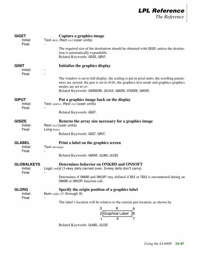
LPL ReferenceThe Reference
Using the LI-6400 24-45
GIGET Capture a graphics imageInitial: Text dest, Rect rect (user units)Final: -
The required size of the destination should be obtained with GISIZE, unless the destina-tion is automatically expandable.Related Keywords: GISIZE, GIPUT.
GINIT Initialize the graphics displayInitial: -Final: -
The window is set to full display, the scaling is put in pixel units, the scrolling param-eters are zeroed, the pen is set to (0,0), the graphics-text mode and graphics-graphicsmodes are set to or.Related Keywords: GWINDOW, GSCALE, GMODE, GTMODE, GMOVE.
GIPUT Put a graphics image back on the displayInitial: Text source, Rect rect (user units)Final: -
Related Keywords: GIGET.
GISIZE Returns the array size necessary for a graphics imageInitial: Rect rect (user units)Final: Long bytes
Related Keywords: GIGET, GIPUT.
GLABEL Print a label on the graphics screenInitial: Text messageFinal: -
Related Keywords: GMOVE, GLORG, GLSIZE
GLOBALKEYS Determines behavior on ONKBD and ONSOFTInitial: Logic onOff (1=key defs carried over, 0=key defs donÕt carry)Final: -
Determines if ONKBD and ONSOFT stay defined if IDLE or TIDLE is encountered during anONKBD or ONSOFT function call.
GLORG Specify the origin position of a graphics labelInitial: Num value (1 through 9)Final: -
The labelÕs location will be relative to the current pen location, as shown by
Related Keywords: GLABEL, GLSIZE
321
654
987
Graphics Label

LPL ReferenceThe Reference
24-46 Using the LI-6400
24
GLSIZE Get the size (in pixels) of a graphics labelInitial: Text theLabelFinal: LONG height, LONG width
Related Keywords: GLABEL, GLORG
GMODE Set the graphics drawing modeInitial: Num newMode (0=none, 1=or, 2=eor, 3=and, 4=not)Final: -
Related Keywords: GMDGET. See Drawing Modes on page 23-62.
GMOVE Absolute move. Pen moved without drawing.Initial: Point pFinal: -
Related Keywords: GRMOVE, GWHERE.
GMDGET Returns current graphics drawing modeInitial: -Final: Long oldMode (0=none, 1=or, 2=eor, 3=and, 4=not)
Related Keywords: GMODE. See Drawing Modes on page 23-62.
GPGET Is pixel at this location on or offInitial: Point point (user units)Final: Long 1 (on) or 0 (off).
Related Keywords: GSCALE, GPPUT, GIGET.
GPLOT Plot characters or draw a lineInitial: Num code (0=line, non-zero=plot), NArray horizUserUnits, NArray vertUserUnitsFinal: -
If code is not zero, it is interpreted as the character to be plotted. Otherwise, a line isdrawn connecting the coordinates. Related Keywords: GSCALE, GMODE.
GPPUT Write a pixel at the specified locationInitial: Point userUnitsFinal: -
Related Keywords: GSCALE, GPGET, GICON.
GRAPH Turns on/off the graphics display.Initial: Logic onOff (1=on, 0=off)Final: -
Related Keywords: ALPHA, GETALPHA, GETGRAPH.
GRDRAW Draws relative to the current pen locationInitial: Point userUnitsFinal: -
Related Keywords: GSCALE, GRMOVE, GDRAW.

LPL ReferenceThe Reference
Using the LI-6400 24-47
GRMOVE Relative moveInitial: Point userUnitsFinal: -
Related Keywords: GMOVE, GSCALE, GWHERE.
GSCALE Scale the current graphics windowInitial: Rect userUnitsFinal:
All subsequent pen movements are according to this scaling. Windows and Coordi-nates on page 23-58
GSCGET Returns the current graphics scaling factorsInitial: -Final: Double xMin, Double xMax, Double yMin, Double yMax
-or-Initial: Rect scalingFinal: Rect scaling
Related Keywords: GSCALE.
GSCROLL Enables/disables automatic graphics window scrollingInitial: Num horizPixels, Num vertPixelsFinal: -
Enables/disables automatic scrolling in the horizontal and vertical. Automatic scroll-ing will occur whenever the pen is moved or drawn out of the current graphics win-dow. If scrolling is enabled, the graphics window scaling is automatically adjusted tokeep the new pen location visible. Note that when scaling is adjusted, both max andmin values are adjusted by the same amount.
GSHIFT Shift part of the graphics displayInitial: Num dx, Num dy, Rect userUnitsFinal: -
Related Keywords: GSCROLL.
GTMDGET Returns current graphics-text drawing modeInitial: -Final: Long currentMode (1=or, 2=eor, 3=and)
Related Keywords: GTMODE.
GTMODE Set the graphics-text drawing modeInitial: Num newMode (1=or, 2=eor, 3=and)Final: -
This affects what is seen when both graphics and text are visible on the same displaydevice.Related Keywords: ALPHA, GRAPH, GTMDGET.

LPL ReferenceThe Reference
24-48 Using the LI-6400
24
GWHERE Returns the pen locationInitial: -Final: Double userHoriz, Double userVert
Related Keywords: GSCALE.
GWIDTH Returns the width of the graphics window in pixelsInitial: -Final: Long pixelsWide
Related Keywords: GHEIGHT, GWINDOW.
GWIGET Gets the current graphics windowInitial: -Final: Long left, Long top, Long right, Long bottom
-or-Initial: Rect theWindowFinal: Rect theWindow
Units are Pixel Hardware Coordinates.Related Keywords: GWINDOW
GWINDOW Define a graphics windowInitial: Rect newWindowFinal: -
Units are pixel hardware coordinates. User scaling is not affected by this command -the user scaling will be in effect in the new window.Related Keywords: GWIGET.
HALT Terminate an IDLE or TIDLEInitial: -Final: -
Related Keywords: IDLE, TIDLE
HASCOPRO Is there a coprocessor installed?Initial: -Final: Long Logic (1=yes, 0=no)
HIDESOFT Hide the function key labels, if anyInitial: -Final: -
Related Keywords:SHOWSOFT
HSCOUNTS High speed counterInitial: -Final: Long counts
Returns the number of counts from the high speed counter since the previous call toHSCOUNTS. See Pulse Counting on page 26-27.

LPL ReferenceThe Reference
Using the LI-6400 24-49
IDLE Wait for interrupt eventsInitial: -Final: -
Related Keywords:TIDLE. See Event Handling on page 23-33.
IF Program flow controlInitial: Num LogicFinal: -
Related Keywords: ELSE, THEN.
INT Returns the code value for type INTInitial: -Final: LONG typeVal
Related Keywords: CHAR, LONG, FLOAT, DOUBLE, PTR, MAKE, MAKE4.
INTERPOL Interpolate using two arraysInitial: NArray yArr, NArray xArr, Num xFinal: Double y
The x value is interpolated using xArr, and the corresponding interpolated yArr valueis returned. The xArr array must be sorted in ascending or descending order.
IOCLEAR Clears the error code for a pathInitial: Addr pathFinal: -
Related Keywords: IOERR
IOERR Returns the latest error (if any) for a path operationInitial: Addr path Final: LONG errorNumber (0=none, 1= read EOF, 2 = write EOF, 3 = seek EOF)
See I/O Errors on page 23-45.Related Keywords: IOCLEAR
ISEMPTY Is a path empty?Initial: -Final: LONG logic (1 = empty, 0 = not empty)
Related Keywords: PATHSTAT
ISLINK Is a module linked Initial: Text name, Num sysID
-or-Initial: Num number, Num sysIDFinal: Long logic (1 = yes, 0 = no)
Modules can be referenced by their file specifier (name), or else by their number. IfsysID is 0, the current application is used.Related Keywords: LINK, UNLINK, SYSID, SETMODNUM, GETMODNUM

LPL ReferenceThe Reference
24-50 Using the LI-6400
24
KBD Provides the standard path to the keyboardInitial: -Final: Addr path
This path is common to all applications, and cannot be closed by any of them.Related Keywords:LCD, ARGS, COMM
KBDCLICK Enable or disable a beep on each keystrokeInitial: Num onOff (0=off, 1=on)Final: -
Related Keywords: BEEP
KBDDELAY Set the delay time for keyboard repeatsInitial: Num milliSecsFinal: -
KBDEXEC Enter LPLÕs keyboard execution modeInitial: -Final: -
The user is continually prompted (Òok>Ó) to enter function code. Each time the userpresses enter, the entry is compiled and executed. esc exits this mode.Related Keywords: COMPILE.
KBDREPEAT Set the repeat interval when a key is held downInitial: Num milliSecsFinal: -
LCD Provides the standard path to the displayInitial: -Final: Addr path
This path is common to all applications, and cannot be closed by any of them.Related Keywords:COMM, ARGS, KBD
LGT Log base 10Initial / Final: (See Single Value Transforms on page 24-13.)
Related Keywords:LOG
LINK Load and compile source code, and link it to an existing application.Initial: [Num sysID, Addr messPath, Num code], Text modName, Addr sourcePath
-or-Initial: [Num sysID, Addr messPath, Num code], Text fileName, Num anythingFinal: Long error (0=ok, non-zero = failed)
To link a file, have any numeric value on the top of the stack. Otherwise, have a path
For a discussion of the KBD_ keywords, see Keyboard Control on page 23-29.
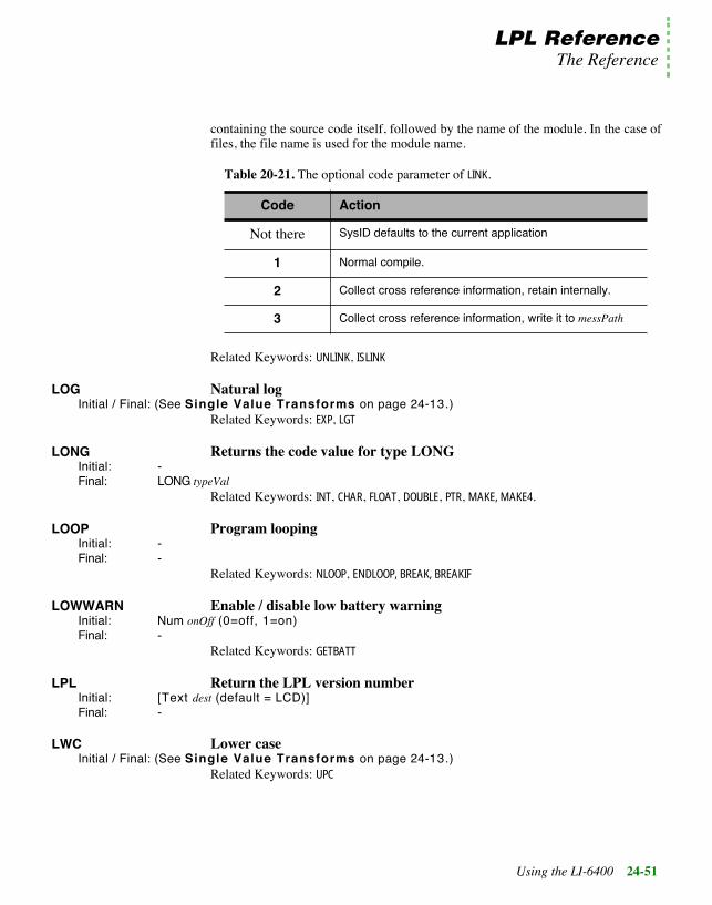
LPL ReferenceThe Reference
Using the LI-6400 24-51
containing the source code itself, followed by the name of the module. In the case offiles, the file name is used for the module name.
Related Keywords: UNLINK, ISLINK
LOG Natural logInitial / Final: (See Single Value Transforms on page 24-13.)
Related Keywords: EXP, LGT
LONG Returns the code value for type LONGInitial: -Final: LONG typeVal
Related Keywords: INT, CHAR, FLOAT, DOUBLE, PTR, MAKE, MAKE4.
LOOP Program loopingInitial: -Final: -
Related Keywords: NLOOP, ENDLOOP, BREAK, BREAKIF
LOWWARN Enable / disable low battery warningInitial: Num onOff (0=off, 1=on)Final: -
Related Keywords: GETBATT
LPL Return the LPL version numberInitial: [Text dest (default = LCD)]Final: -
LWC Lower caseInitial / Final: (See Single Value Transforms on page 24-13.)
Related Keywords: UPC
Table 20-21. The optional code parameter of LINK.
Code Action
Not there SysID defaults to the current application
1 Normal compile.
2 Collect cross reference information, retain internally.
3 Collect cross reference information, write it to messPath

LPL ReferenceThe Reference
24-52 Using the LI-6400
24
MAKE Dynamic array allocationInitial: Num typeCode, Num numElementsFinal: Array newArr, Long 0
-or-Final: Long 1
IMPORTANT: When an application goes out of scope (ends), any arrays that havebeen allocated but not FREEd are disposed of automatically.Related Keywords: FREE, MEM, MAKE4.
MAKE4 Dynamic array allocationInitial: Num typeCode, Num numElements, NUM sysIDFinal: Array newArr, Long 0
-or-Final: Long 1
Allocates an array for a particular application. IMPORTANT: When an applicationgoes out of scope (ends), any arrays that have been allocated but not FREEd are disposedof automatically.Related Keywords: FREE, MEM, MAKE
MAKESOFT Create function key structureInitial: Num de, Num dc, Num le, Num nLines, Num mode, Num nKeysFinal: -
See The Function Keys on page 23-37.
Related Keywords: FREESOFT, ONSOFT
MATHERR Enable / disable math error correctionsInitial: Num onOff (0 = report errors, 1=overlook errors)Final: -
The following math errors normally generate fatal errors, but they can be overlooked
Table 24-24. MAKESOFT parameters
de Delimiter enhancement Table 24-37 on page 24-67
dc Delimiter character.
le Label enhancement. Table 24-37 on page 24-67
mode 0 always on, 1 save beneath
nKeys number of keys

LPL ReferenceThe Reference
Using the LI-6400 24-53
with MATHERR:
MAX Return maximum valueInitial / Final: (See Two Value Transforms on page 24-13.)
MEM Returns memory statusInitial: -Final: Long largestBytes, Long totalBytes
MEMMAP Prints allocation information about the heapInitial: [Path dest (default = COMM)]Final: -
MESSBOX Pop up a boxed messageInitial: Num mode (=0), [Num pos1, Text lab1, [Num pos2, Text lab2]] Text messgeFinal: -
-or-Initial: Num mode (=1), [Num pos1, Text lab1, [Num pos2, Text lab2]] Text messgeFinal: LONG keyCode
-or-Initial: Text keys, Num 2, [Num pos1, Text lab1, [Num pos2, Text lab2]] Text messgeFinal: LONG keyCode
Mode 0:does not pause execution to wait for the user. The message goes up, and exe-cution continues. There is no automatic cleanup. Mode 1:waits for the user to press any key after the message is displayed. When thishappens, the message and frame go away, and the underlying display is restored. If noframe labels are defined, ÒPress Any KeyÓ will appear on the lower frame. Mode 2:also waits for a user keystroke, except that the allowed keys are specified. es-cape is always assumed to be an allowed key.
MIN Returns min valueInitial / Final: (See Two Value Transforms on page 24-13.)
Related Keywords:MAX
Table 24-25. Math Errors Fixed by MATHERR
Error How Fixed
Divide by 0 Result is 0
Argument out of range Result is 0
Negative number raised to a non-integer power
Result is 0

LPL ReferenceThe Reference
24-54 Using the LI-6400
24
MOD Returns the remainder of A/BInitial / Final: (See Two Value Logical Transforms on page 24-15.)
MODSIZE List compiler size directive settings for all modules in an applicationInitial: Num low, Num High, Addr path, [Num SysID]Final: -
Starts at module number low, and proceeds through module number high. For eachmodule, the following information is written to path. This function is useful for Òtun-ingÓ moduleÕs compiler directives for efficient use of memory. A program to do thisis “/Sys/Lib/UpdateSizes”.
:CODE nn:DATA nn:NAMES nn:PRIVCOUNT nn:PUBCOUNT nn:STATCOUNT nn
MOVETEXT Copy a block of text and attribute within a text windowInitial: Num toLeft, Num toTop, Rect area Final: -
toLeft, toTop, and area are in relative window coordinates.
NEXTKEY See what is next in the keyboard queue, without removing itInitial: Num -Final: NUM result (keyCode or -1 if queue is empty)
To decode keyCode, see Keyboard Codes on page 23-29.Related Keywords: GETKEY, UNGETKEY
NLOOP Loop a finite number of timesInitial: Num nFinal: -
Related Keywords: LOOP, ENDLOOP, BREAK, BREAKIF
NOT Logical NOTInitial / Final: (See Single Value Transforms on page 24-13.)
OFFA2D Disable an ONA2D conditionInitial: -Final: -
Related Keywords:ONA2D
OFFCOMM Disable ONCOMM conditionInitial: -Final: -
Related Keywords:ONCOMM

LPL ReferenceThe Reference
Using the LI-6400 24-55
OFFCYCLE Disable an ONCYCLE timerInitial: Num timerNum (1, 2, or 3)Final: -
Related Keywords:ONCYCLE
OFFKBD Disable ONKBD conditionInitial: -Final: -
Related Keywords:ONKBD
OFFSOFT Disable ONSOFT for a keyInitial: Num keyNumFinal: -
Related Keywords:ONSOFT
OFFTIC Disable ONTIC timerInitial: -Final: -
Related Keywords:ONTIC
OFFTIME Disable ONTIME alarmInitial: -Final: -
Related Keywords:ONTIME
ONA2D Enable interrupt when an A/D group is readyInitial: Fct funtion, Num groupNumFinal: -
Related Keywords: IDLE, TIDLE, OFFA2D
ONCOMM Enable interrupt when a target char is received on the Comm portInitial: Num character, Fct functionFinal: -
Execute function every time character is received during the ongoing or subsequent(T)IDLE. An overlapped transfer (XFER) from the comm port must be ongoing.Related Keywords: IDLE, TIDLE, OFFCOMM
ONCYCLE Enable interrupt of a timerInitial: Num seconds, Num timerNum (1, 2, or 3), Fct functionFinal: -
Define a function to be periodically called during the ongoing or subsequent (T)IDLE.This is the same idea as ONTIC, except the period is user defined, and up to three differ-ent periods can be used during one (T)IDLE. Each application has 3 cycle timers thatare independent from any other application. The timers are global to any (T)IDLEwithin an application, however. Thus, any function called from within a (T)IDLE canmodify any timerÕs parameters (period and function address), and the changes remainin effect until another ONCYCLE or OFFCYCLE is encountered.

LPL ReferenceThe Reference
24-56 Using the LI-6400
24
Related Keywords: IDLE, TIDLE, OFFCYCLE
ONKBD Enable interrupt when a keystroke is availableInitial: Fct functionFinal: -
Define a function to be called every time a keystroke is available during the next(T)IDLE. See also GLOBALKEYS. To access the keystroke that is available, use GETKEY.Related Keywords: IDLE, TIDLE, OFFKBD
ONSOFT Enable interrupt when a function key is pressedInitial: Text label, Fct function, Num keyNumFinal: -
Define a label and action for a function key to be performed at the next (T)IDLE (or theongoing (T)IDLE, depending on GLOBALKEYS). MAKESOFT must first have been performedto build space for the function key information.ONKBD and ONSOFT interaction: If no function keys are defined (MAKESOFT not in effect),then any function key stroke is passed to the ONKBD function. If function keys are de-fined (MAKESOFT in effect), then function key strokes do not pass through to the ONKBDfunction. If function keys are defined, but a function key is pressed for which no ON-SOFT function was defined, then that keystroke is ignored.Related Keywords: IDLE, TIDLE, OFFSOFT
ONTIC Enable a 1 second interruptInitial: Fct functonFinal: -
Related Keywords: IDLE, TIDLE, OFFTIC
ONTIME Enable an alarm clock interruptInitial: Num timeDateSecs, Fct functionFinal: -
Define a function to be executed once when a certain time is reached. If this time oc-curs when there is no (T)IDLE in effect, then the function will not be executed until thenext (T)IDLE.Related Keywords: IDLE, TIDLE, OFFTIME

LPL ReferenceThe Reference
Using the LI-6400 24-57
OPEN_BUFF Open a path to an expandable memory bufferInitial: Num initialSizeFinal: Addr path, Long 0
-or-Final: Long 1
Related Keywords: CLOSE
OPEN_CHARS Open a path to an char arrayInitial: CArray stringFinal: Addr path, Long 0
-or-Final: Long 1
The initial fill value is set to the ready value of the array (see Array SIZE andREADY values on page 23-6) After the path is closed, the ready value is set from thefill value of the path. While the path is open, bear in mind that you have two indepen-dent methods of manipulating data in the character array: the path keywords (PRINT,ENTER, etc.) and the normal array keywords (APP, ENTER, etc.), and also that there is noimmediate interaction between the SETREADY keyword and the SETFILL or SETEMPTY key-words. Related Keywords: CLOSE
OPEN_COMM Open a path to the Comm portInitial: -Final: Addr path, Long 0
-or-Final: Long 1
Every application has available to it the standard path COMM. One reason to open an-other path to the comm port would be to implement different filtering without chang-ing the standard filters associated with COMM.Related Keywords: CLOSE
OPEN_FILE Open a path to a fileInitial: Text opts, Text nameFinal: Addr path, Long 0
-or-Final: Long 1
The opts string is made up of one or more of the items in Table 24-26. For example,ÒwaÓ is write-append.
For a discussion of the OPEN_ keywords, see I/O Programming on page 23-39.

LPL ReferenceThe Reference
24-58 Using the LI-6400
24
Related Keywords: CLOSE
OPEN_FILE_ASK Open a file using the Standard File DialogInitial: Num opts, Text name, Text prompt, [Text helpInfo, Num code]Final: Addr path, Long 0
-or-Final: Long 1
Open a file using the operating systemÕs Standard File Dialog box.
If opts is 1 or 2, and the file exists, the user is asked if the file is to be overwritten orappended.Related Keywords:CLOSE
OPEN_KBD Open a path to the keyboardInitial: -Final: Addr path, Long 0
-or-Final: Long 1
Every application has available to it the standard path KBD. One reason to open anotherpath to the keyboard would be to implement different filtering without changing thestandard filters associated with KBD.Related Keywords:CLOSE
Table 24-26. Options for FILE_OPEN
opts File exists File doesnÕt exist
r ok Error
w Opened and truncated File created
a Opened for appending File created
Table 24-27. OPEN_FILE_ASK parameters
code Optional. Value doesnÕt matter. The presence of anumeric value here indicates that the next item onthe stack is help text.
helpInfo If code is present. The text to be displayed in to di-alog box if the user presses the HELP key.
prompt The prompt to be used in the dialog box.
name The starting name of the file to be opened. On re-turn, holds the selected name.
opts 0 = read only, 1 = write only, 2 = read and write.

LPL ReferenceThe Reference
Using the LI-6400 24-59
OPEN_LCD Open a path to the displayInitial: -Final: Addr path, Long 0
-or-Final: Long 1
Every application has available to it the standard path LCD. One reason to open an-other path to the display would be to implement different filtering without changingthe standard filters associated with LCD.Related Keywords:CLOSE
OPEN_QUE Open a path to a circular queueInitial: Num initialSizeFinal: Addr path, Long 0
-or-Final: Long 1
The actual size of the queue may differ from the requested size. Queues are sized 7,15, 31, 63, 127, 255, 511, 1023, 2047, 4095, 8191, 16383, or 32767 bytes. If a differentvalue is requested, the next largest size is used, but is never larger than 32767.Related Keywords: CLOSE
OR Logical ORInitial / Final: (See Two Value Logical Transforms on page 24-15.)
Related Keywords: AND, NOT
PATHSTAT Get status information for a pathInitial: Num code, Addr PathFinal: LONG value
-or-Final: LONG type, LONG size, LONG fill, LONG empty
code and type are given in Table 24-28, and Table 24-29.
Table 24-28. PATHSTAT Code Values
code value
1 Path type: See Table 24-29
2 Path size
3 Path fill
4 Path empty

LPL ReferenceThe Reference
24-60 Using the LI-6400
24
PDRF Pointer dereferenceInitial: Addr ptrFinal: Addr object
Returns the object directly pointed at, if ptr is a pointer. PVAL, on the other hand, tracksa pointer to itÕs ultimate non-pointer object.Related Keywords: PVAL
PFIND Finds a pointer referenced in a pointer arrayInitial: Parray arr, Addr targetFinal: Long subscript (or 0 if not found)
Related Keywords: PVAL, FIND. See Using PTR arrays on page 23-13.
PICK Return address of an element in an arrayInitial: Array arr, Num subscript
-or-Initial: Num subscript, Array arrFinal: Addr address
If subscript is 0 or greater than the array size, an error will result.Related Keywords: VAL, PVAL, SIZE. See Array Operations on page 23-6.
POLY Computes a polynomialInitial: Double Array coeffs, Num argFinal: Double result
The power of the polynomial is determined from the number of values in the coeffi-cient array coeffs. 2 values = 1st order, 3 values = 2nd order, etc.
POSXY Position the cursor within the current text windowInitial: Num column, Num rowFinal: -
Related Keywords: GETWINDOW.
Table 24-29. Path Types
Type Path to... Type Path to...
0 keyboard 5 circular queue
1 display 6 file (read only)
2 comm port 7 file (write only)
3 CHAR array 8 file (read + write)
4 memory buffer

LPL ReferenceThe Reference
Using the LI-6400 24-61
POWEROFF Powers off the instrumentInitial: -Final: -
PRINT Print to a pathInitial: ..., [CArray fmtString], [PATH dest (default = LCD)]Final: -
Print and PointersPRINT starts adding characters to a path at the fill pointer location. As characters areadded, the fill pointer is updated.
The Format StringCharacters contained in the format string are output to the destination path, except forformat specifier fields, which take the form
% [(number [delim]]) [flags] [width] [.precision] type
Table 24-30. Format string elements for PRINT
(number [delim]) Optional. Used when outputting an array. Num-ber can be the number of elements to output, or *for all elements. The optional delim character isused, if specified, as the delimiter between ele-ments.
flags Optional. The flag characters are -, +, and space,as indicated by Table 24-31
width Optional. If present, specifies the minimum num-ber of characters to print, padding with blanks orzeros.
precision Optional. If present, specifies the maximumnumber of characters to print; for integers, mini-mum number of digits to print.
type Must be present. Specifies the type of item to beprinted. Note that what is popped from the stackis converted to this type. See Table 24-32 onpage 24-62
Table 24-31. PRINT Flag Characters
Flag Meaning
- Left justifies the result, pads on the right with blanks. Ifnot given, right-justifies the result, pads on the left withzeros or blanks.
+ Numeric values always begin with a + or - sign.

LPL ReferenceThe Reference
24-62 Using the LI-6400
24
(space) If the value is non-negative, output begins with a blankinstead of a plus; negative values still begin with a mi-nus.
Table 24-32. PRINT Type Codes
Type Meaning Type Meaning
d or i signed int f floating point
o signed octal int e scientific notation with e
u unsigned decimal int E scientific notation with E
x or X unsigned hex int g floating point in e or f form,based on precision.
ld or li signed long G floating point in E of f form,based on precision.
lo signed octal long c character
lx or lX unsigned hex long s string
lu unsigned decimal long p pointer address
k outputs an unsigned int as \kHHLL, where HH is the high byte in hex,and LL is the low byte in hex.
Table 24-33. PRINT Format Examples
Item on Stack Format Result
12 (LONG) %8d " 12"
"abcdefg" %5.5s "abcde"
1.2345 %7.2f " 1.23"
1.2345 %-7.1f" "1.23 "
"ABC" "(*,)d" "65,66,67"
Table 24-31. (Continued)PRINT Flag Characters
Flag Meaning

LPL ReferenceThe Reference
Using the LI-6400 24-63
PRINT and PTR ArraysThere should be a % specifier in the format string for each non-pointer array item inthe pointer array.
Unformatted PRINTIf no format string is found, then one item on the stack is printed using a default for-mat, based on the type of item that is found (Table 24-34).
PTR Returns the code for type PTRInitial: -Final: LONG typeVal
Related Keywords: INT, LONG, FLOAT, DOUBLE, CHAR, MAKE, MAKE4.
PTRTOLL Converts an LPLÕs address into address and typeInitial: ADDR PtrFinal: Long address, LONG type
Related Keywords:USES
PUTCH Add a character to a pathInitial: Num theChar, Addr PathFinal: LONG result (theChar if ok, or -1 on error)
Related Keywords: GETCH
PUTDISP Redisplay text and attribute informationInitial: DispInfo oldFinal: -
This disposes the structure pointed at by old, so donÕt use it again!Related Keywords: GETDISP
Table 24-34. PRINT Default Formats
Stack Object Format Used Stack Object Format Used
LONG %ld DOUBLE Addr %lG
DOUBLE %lG CArray %s
CHAR Addr %c INT Array %(* )d
INT Addr %d LONG Array %(* )ld
LONG Addr %ld FLOAT Array %(* )g
FLOAT Addr %f DOUBLE Array %(* )lg

LPL ReferenceThe Reference
24-64 Using the LI-6400
24
PUTTEXTInitial: Rect area, Text source, [Num attr]Final: -
area uses absolute display coordinates. attr, if present, is imposed on the rectangle. Ifmissing, attributes are unchanged.Related Keywords: GETTEXT.
PUTWINDOW Implements window, attribute, and cursor informationInitial: NArray sourceFinal: -
Related Keywords: GETWINDOW
PVAL Returns the address pointed atInitial: PAddr p Final: PAddr final
Related Keywords: VAL
RAD Enable Òradians modeÓ for trig functions.Initial: -Final: -
Related Keywords:DEG, and all trig functions
RANDOMIZE Randomize the random generator seedInitial: -Final: -
Related Keywords: RND
READY Returns the number of elements in the arrayInitial: Array arrFinal: Long number
Related Keywords: SETREADY, SIZE.
REGRESS Do a linear regressionInitial: Num power, DArray xArray, DArray yArray, DArray coeffs, Num forceZeroFinal: Double determinant
Size of coeffs should be at least as large as 1 + power. If forceZero is true (not 0), thefirst coefficient will always be 0.Related Keywords: POLY

LPL ReferenceThe Reference
Using the LI-6400 24-65
RESET Sets fill and empty pointers to 0Initial: Addr pathFinal: -
RESETDFC Reset the default convertout and convertin filters for filesInitial: -Final: -
Platform specific - See Table 24-35. See Path Filters on page 23-42.
Related Keywords: SETDFCIN, SETDFCOUT, GETDFCIN, GETDFCOUT
RESTART Restart the processor (simulates power off then on)Initial: -Final: -
This is equivalent to pressing shift ctrl escape on the keyboard, and should be doneafter loading a disk image.Related Keywords: POWEROFF
RETURN Exit from a function.Initial: -Final: -
RND Generate and random number between 0 and 1.Initial: -Final: Double value
Related Keywords:RANDOMIZE
ROT Exchange the 1st and 3rd items on the stackInitial: Obj a, Obj b, Obj cFinal: Obj c, Obj b, Obj a
Related Keywords: SWAP, DUP, DROP
RUN Launch an LPL applicationInitial: Path sourceCode
-or-Initial: CArray fileNameFinal: -
Related Keywords: STKSHARE, COMPILE, LINK
Table 24-35. Default File Filters
Platform ConvertOUT ConvertINLI-6400 "e" "e"
DOS "e" "E"
Macintosh "e" "n"

LPL ReferenceThe Reference
24-66 Using the LI-6400
24
SCRLOCK Enable/disable print scrolling in a text windowInitial: Num onOff (0=off, 1=on)Final: -
Scrolling makes the window scroll vertically when filled. No scrolling causes the cur-sor to wrap back to the upper left corner of the window when it fills, and subsequentprinting overwrites the contents character by character. If scrolling is off, cursor goesto top of window.Related Keywords: MOVETEXT
SEARCH Search a path for a target stringInitial: Path text, Text target, [Num flag]Final: Long return (1 if found, 0 if not)
flag given in Table 24-36. The path pointers are changed only if return is not 0.
SECS2TD Convert seconds since base time to time and dateInitial: Num secsSinceBaseFinal: Num secs, Num min, Num hour, Num day, Num month, Num year
Convert seconds since base time to the time and date (numerical)Related Keywords: TD2SECS, TIME, DATE, CTIME
SETATTR Set text attribute for subsequent printingInitial: Num newValue Final: -
Attributes (value of newValue) are given in Table 24-37.
Table 24-36. SEARCH Options
flag Result (if target found)
0 DonÕt move pointers.
1 Move empty pointer to start of match
2 Move empty pointer to after match
3 Move fill pointer to start of match
4 Move fill pointer to after match

LPL ReferenceThe Reference
Using the LI-6400 24-67
Related Keywords: GETWINDOW, WINDOW
SETCURSOR Set the cursor typeInitial: Num newValue (0=none, 1=underline, 2=full height)Final: -
Related Keywords: GETWINDOW.
SETDFCIN Sets default filters (convertin) for files.Initial: Text stringFinal: -
See Path Filters on page 23-42.Related Keywords: SETDFCOUT, GETDFCIN, GETDFCOUT, RESETDFC.
SETDFCOUT Sets default filters (convertout) for files.Initial: Text stringFinal: -
See Path Filters on page 23-42.Related Keywords:SETDFCIN, GETDFCIN, GETDFCOUT, RESETDFC.
SETEMPTY Sets the empty pointer for a pathInitial: Num offsetBytes, Num Ref (from: 0=start, 1=current, 2=end), Addr PathFinal: -
Related Keywords:PATHSTAT, SETFILL
SETFILL Set the fill pointer for a pathInitial: Num offsetBytes, Num Ref (from: 0=start, 1=current, 2=end), Addr PathFinal: -
Related Keywords: PATHSTAT, SETEMPTY
SETID Change the owner of on allocated item or A/D structureInitial: Num newID, Addr objectFinal: -
Related Keywords: MAKE, MAKE4, SYSID
Table 24-37. Text attributes
Attr ibute Description
0 None
1 Inverse video
2 Blinking
3 Inverse video and blinking

LPL ReferenceThe Reference
24-68 Using the LI-6400
24
SETMODNUM Set the module number for an applicationInitial: Num value, Num sysIDFinal: -
The next module to be linked will have number 1 plus this value. If sysID is <=0, thecurrent application is assumed.Related Keywords: GETMODNUM
SETREADY Sets the ready value of an arrayInitial: Num newVal, Array arr
-or-Initial: Array arr, Num newValFinal: -
Setting the ready value to 0 effectively empties the array. SETREADY never alters thecontent of an array - it only changes the ready value in the arrayÕs header.Related Keywords: READY, SIZE.
SETTARGET Sets the search target for the system editorInitial: Text targetFinal: -
Related Keywords: GETTARGET.
SETTDS Sets the system clockInitial: Num secsFromBaseFinal: -
Related Keywords: GETTDS, TD2SECS.
SHOW Show n items on the stackInitial: Num numItems, [Path dest (default = LCD)]Final: -
SHOW does not affect the stack (unless pushing numItems and dest onto the stack to doSHOW causes a stack overrun).
SHOWSOFT Cause the function key labels (if any) to be displayedInitial: -Final: -
Related Keywords: HIDESOFT
SIN Computes sineInitial / Final: (See Single Value Transforms on page 24-13.)
Related Keywords: DEG, RAD.
SIZE Returns maximum size of an arrayInitial: Array arrFinal: Long size
Related Keywords: READY

LPL ReferenceThe Reference
Using the LI-6400 24-69
SOFTGETM Returns the current function key menu levelInitial: -Final: LONG level (0=1st, -1 = none defined)
Related Keywords: SHOWSOFT, SOFTSETM
SOFTSETM Sets the function key menu levelInitial: LONG newLevel (0=1st)Final: -
Does NOT redisplay key labels.Related Keywords: SOFTGETM, SHOWSOFT
SOFTWIDE Returns the number of function keys that can be displayedInitial: -Final: LONG nKeys (5 for the LI-6400)
SQRT Square rootInitial / Final: (See Single Value Transforms on page 24-13.)
Related Keywords: MATHERR
STDEDIT Invokes the system editor using the current text windowInitial: [Text filename], Text toEditFinal: -
If filename is present, pressing escape will bring up the exit menu.Related Keywords: STDMENU, STDLINE, EDOPEN
STDLINE Edits a line of textInitial: Text lineFinal: LONG result (1=enter pressed, 0=escape pressed)
The window is borderless and lies between the current cursor position and the rightedge of the active text window. If the text object is too large to fit in the window, thetext scrolls horizontally in the window.
NOTE: The text object changes regardless of whether or not the user exits by pressingescape or enter. If you wish escape to leave the object unchanged, then use STDLINEon a copy of the object.Related Keywords: STDEDIT.
STDMENU Invoke the standard menu interfaceInitial: [Text bannerLabel], Num flag, Text exitKeys, Text menuItemsFinal: LONG exitKey
Do Standard Menu. If bits 3 or 4 of flag are set, then bannerLabel is expected on thestack. A label banner will scroll left and right as the text window scrolls left and right.

LPL ReferenceThe Reference
24-70 Using the LI-6400
24
Related Keywords: STDEDIT, EDOPEN
STKCHECK Enable/disable stack overflow error reportingInitial: Num onOff (0=off, 1=on)Final: -
A stack overflow occurs when too many items are pushed onto the stack. If reported,it is a non-fatal error.Related Keywords: STKSIZE, STKRESIZE
STKREADY How many items are on the stackInitial: -Final: LONG elements
Related Keywords: SHOW, ADR?
STKRESIZE Change the stack sizeInitial: Num newSize (number of items)Final: -
This also flushes the stack.Related Keywords: STKSIZE
STKSHARE Enable/disable stack sharingInitial: Num yesNo (0=no sharing, non-zero=stack sharing)Final: -
Stack sharing applies to subsequent child applications launched by the current appli-
Table 24-38. StdMenu Flag.
Bit Value Description
0 1 Highlighted menu bar
1 2 Put cursor to start of current line at exit
2 4 Use currently defined softkey labels
3 8 Fixed banner (e.g. a file name)
4 16 Label banner (e.g. column labels).
5 32 Show position marker on banner
7 64 Show byte marker on banner
For a discussion of the STK_ keywords, see Stack Control on page 23-2.

LPL ReferenceThe Reference
Using the LI-6400 24-71
cation.Related Keywords: RUN
STKSIZE How many items can the stack hold?Initial: -Final: LONG numElements
Related Keywords: STKREADY, STKRESIZE
STRIP Strip token names and cross reference information from the current ap-plication
Initial: -Final: -
Note that this recovers space, but destines subsequent COMPILE and KBDEXEC commandsto failure if they contain any references to objects in this application.
SUBSET Create an array subset Initial: Array arr, Num first, Num lastFinal: Array tempHdr
Creates an array header for a subset of an existing array. This is convenient for limitingsearches, or confining transformations to a region of an array whose lower bound isnot 1. (When the lower bound is 1, you can accomplish the same thing by setting theready value (SETREADY) temporarily). IMPORTANT: tempHdr is created on the localvariable stack, so becomes invalid once the current function is exited.
SUM Returns the sum of numeric objects in an arrayInitial: Array aFinal: LONG or DOUBLE sum
An alternative is
0 array +
SWAP Exchange the top two items on the stackInitial: ..., Obj a, Obj bFinal: ..., Obj b, Obj a
Related Keywords: DUP, DROP, ROT
SYSID Returns the system ID number for the current applicationInitial: -Final: LONG sysID
Related Keywords: SETID
TAN TangentInitial / Final: (See Single Value Transforms on page 24-13.)
Related Keywords: DEG, RAD.

LPL ReferenceThe Reference
24-72 Using the LI-6400
24
TD2SECS Convert time and date to seconds since the system base timeInitial: Num secs, Num min, Num hour, Num day, Num month, Num yearFinal: LONG tdSecs
Related Keywords: SECS2TD, GETTDS, TIME, DATE, CTIME
THEN Required termination keyword for IFInitial: -Final: -
Related Keywords:IF, ELSE
TIDLE Wait for interrupts for a certain period of timeInitial: Num secondsFinal: -
Related Keywords: IDLE
TIME Convert seconds since base time to time of dayInitial: Num tdSecsFinal: LONG secs (0..59), LONG mins (0..59), LONG hrs (0..23)
Related Keywords: DATE, GETTDS, CTIME, SECS2TD, TD2SECS.
TYPE Returns the type of the object on the stackInitial: Obj aFinal: Obj a , LONG type
UNGETCH Put a character back into a pathInitial: INT charCode, Addr pathFinal: LONG result (charCode or -1 if path is full)
Related Keywords:GETCH, PUTCH
UNGETKEY Put a back into the keyboard queueInitial: INT keyCodeFinal: LONG result (keyCode or -1 if queue is full)
Related Keywords:GETKEY, NEXTKEY
UNLINK Remove one or more modules from an applicationInitial: Num all, Num moduleNumber, Num sysID
-or-Initial: NUM all, Text moduleName, Num sysIDFinal: Long error (0=ok, 1=failed)
The module to be removed can be refereed to by name or number. If all is non-zero,all modules having a number greater than or equal to the targetÕs number are removed.Related Keywords:LINK, ISLINK
UPC Uppercase functionInitial / Final: (See Single Value Transforms on page 24-13.)
Related Keywords:LWC

LPL ReferenceThe Reference
Using the LI-6400 24-73
USES List the cross reference information for an objectInitial: Addr path, Num 1, Text name [, Num sysID]
-or-Initial: LArray longArray, IArray intArray, Num 2, Text name [, Num sysID]Final: -
The symbol name is looked up in the symbol table, and cross reference information (ifany) is written to either a path (in which case names are written), or to numeric arrays(in which case addresses and types are written). The cross reference informationcomes from LINK, using control code 2 or 3.Related Keywords: LINK, XREF, PTRTOLL, FINDTOKEN
VAL Get the numeric value of an objectInitial: NAddr aFinal: LONG or DOUBLE value
-or-Initial: PAddr pFinal: Addr final
Related Keywords: PVAL.
WINDOW Open a text window on the displayInitial: Rect area, Num border, [Num pos, Text lab1, [Num pos, Text lab2] ]Final: -
border is 0 (none), 1 (single line), or 2 (double line). Label positions are shown inFigure 24-5.
The right border and/or the bottom border can be suppressed by specifying the right(or bottom) boundary to be any value larger than the DISPWIDTH or DISPHEIGHT value.Related Keywords: CLEAR, SCRLOCK, CLREOL
1 2 3
4 5 6
The Window
Figure 24-5. Window label position codes

LPL ReferenceThe Reference
24-74 Using the LI-6400
24
XFER Copy from one path to anotherInitial: Addr fromPath, Addr toPath, [Num wait | Fct onEnd]Final: -
XREF Generate a cross reference for an applicationInitial: Text filename, Path destFinal: -
Table 24-39. XFER Combinations
To
Keyboard Display CommPort File, Buffer, or Queue
Fro
m
Keyboard Error OK Overlapped Overlapped
Display Error Error Overlapped Overlapped
Comm Port Overlapped Overlapped Error Overlapped
File, Buffer, or Queue
OK OK Overlapped OK

Using the LI-6400 25-1
25AutoProgramming Reference
Making them do what you what them to do
AUTOPROGRAM FORMAT 25-2
SOME AUTOPROGRAM LISTINGS 25-4ÒAutoLogÓ 25-4ÒLightCurveÓ 25-5ÒA-CiCurveÓ 25-6ÒTimed LampÓ 25-8
USEFUL AUTOPROGRAM COMMANDS 25-12Standard Commands 25-12LED Source Control 25-15CO2 Control 25-16Flow Control 25-17Temperature Control 25-18Fan Control 25-18
AUTOPROGRAMS AND THE CONTROL MANAGER 25-19Interaction with Variable Tracking 25-19
LOW LEVEL CONTROL TOOLS 25-19General Control Functions 25-19Flow Control Functions 25-20Mixer Control Functions 25-21Cooler Control Functions 25-22Lamp Control Functions 25-22IRGA Control Functions 25-23Chamber Fan Control Functions 25-24Example: Using the Library 25-24

AutoProgramming Reference
25-2 Using the LI-6400
25There are three levels of dealing with AutoPrograms:
1 Use the default programsOPEN provides some Òready to useÓ.
2 Use the AutoProgram Builder to make your ownThe AutoProgram Builder was introduced with OPEN 3.2, and is describedon page 9-33.
3 Program your ownThis chapter provides the background necessary to write your own fromscratch, or to edit an existing program.
Autoprogram FormatAutoPrograms are small LPL application programs designed to run on top1 ofOPEN. While there is no limit to the scope of what an AutoProgram can bemade to do, typically these programs log data in some sort of automatic fash-ion, while perhaps maintaining control over one or more conditions in the leafchamber.
LetÕs look at a simple but fully functional LPL program that can serve as anAutoprogram. This task is very simple: log five observations spaced oneminute apart to the log file.
1.That is, they will not run successfully unless OPEN is also running.

AutoProgramming ReferenceAutoprogram Format
Using the LI-6400 25-3
We start with one of several functions defined by OPEN for use in AutoPro-grams:
LPPrep
This is required for any AutoProgram which makes use of the commands LP-Measure or LPMeasureTilStable is used. (If you donÕt use the LPPrep func-tion prior to LPMeasure or LPMeasureTilStable, no one will slap your hand,but you might crash the system.)
Repetitive operations can go within LPLÕs loop structure, the NLOOP...END-LOOP pair of keywords. The value on the stack when the NLOOP is encoun-tered specifies the number of times through the loop. Within this structure, the60 second delay is done by
60 LPMeasure
LPMeasure creates a New Measurements mode-like setting for a fixedamount of time, and when it is over, the global variable lpAbort tells us if theuser wishes to abort the program. (This happens when the user presses escapeduring LPMeasure. This brings up the AutoProgram exit dialog box(Figure 25-2 on page 25-13). If the user presses A, lpAbort gets set to 1.) Toabort (if lpAbort is non-zero), we just jump out of the loop.
lpAbort BREAKIF
Data recording is done by
LPLog
which causes a record to be written to the open log file (or RAM file or comm
:FCT main{ LPPrep 5 NLOOP 60 LPMeasure lpAbort BREAKIF LPLog ENDLOOP LPCleanup}
Figure 25-1. A simple AutoProgram.

AutoProgramming ReferenceSome AutoProgram Listings
25-4 Using the LI-6400
25
port). When the AutoProgram is done, some internal housekeeping details aretaken care of by
LPCleanup
which must be used if LPPrep was used.
Some AutoProgram Listings
ÒAutoLogÓ/*
“AutoLog” is described on page 9-22.
Auto logging
970502 - Remembers last time defaults*/
:CHAR defaultFile[] ÒAutoLog dfltsÓ progName[] ÒAUTOLOGÓ :INT logInterval 5quitAfter 5matchEvery 0
This array holds the list of things to be prompted for, with a call to LPPrompts2, below.
:PTR user[] {:PTR { logInterval Ò\nLog every __ secs: Ò }:PTR { quitAfter ÒAdd __ observations: Ò }:PTR { matchEvery ÒAuto match every __ obs (0=none) Ò}}
:FCT main{progName LPSetName
progName Ò\f%sÓ PRINT
defaultFile user LPPrompts2 IF RETURN THEN
0 :INT actual1 :INT i
LPPrepmatchEvery :INT count
quitAfter NLOOPlogInterval &actual =matchEvery IF

AutoProgramming ReferenceSome AutoProgram Listings
Using the LI-6400 25-5
Try to deduct matching time from the log interval time.
&count 1 - VAL NOT IFGETMS :LONG x0LPMatchlogInterval GETMS x0 - 1000 / - &actual =matchEvery &count =THENTHENactual 1 < IF 1 &actual = THEN
quitAfter i LPSetProgress&i 1 + DROP
LPMeasure is where this program spends most of its time.
actual LPMeasurelpAbort BREAKIFLPLogENDLOOPLPCleanup}
ÒLightCurveÓ/*
“Light Curve” is described on page 9-27.
Simple Light Curve, with stability checking
960822 - Tech Note 14 modification, wait time defaults970502 - remembers last time defaults980309 - delta-based matching*/
:CHAR defaultFile[] ÒLightCurve DfltsÓThese default values are used if there is no last-time-defaults file found.
:FLOAT lampVals[20] { 2000 1500 1000 500 200 100 50 20 0 }stable 1.0matchIf 20
:INT minWaitTime 120maxWaitTime 200pmWait 10
:PTR user[] {:PTR { lampVals ÒDesired lamp settings (µmol/m2/s)\nÓ}:PTR { minWaitTime ÒMinimum wait time (secs) Ò}:PTR { maxWaitTime ÒMaximum wait time (secs) Ò}:PTR { stable ÒStability (total CV %) Ò}:PTR { matchIf ÒMatch if |ÆFCO2| less than (ppm) Ò }}
:FCT main{/* Set program name*/ÒLight CurveÓ DUP LPSetNameÒ\f%s\nÓ PRINT

AutoProgramming ReferenceSome AutoProgram Listings
25-6 Using the LI-6400
25
Prompt for user input. defaultFile user LPPrompts2 IF RETURN THEN
LPPrep /* Must be done */
/* Loop over the lamp values*/1 :INT i
Loop over lamp values. lampVals READY LPRegLoop NLOOP LPLoopStat
lampVals i PICK VAL LPSetLamp /* set lamp */
Wait for min time, then for stability.
stable minWaitTime maxWaitTime LPMeasureTilStablelpAbort BREAKIF
Match (fct is below). MatchFctLog. LPLog /* log the data */
&i 1 + DROP /* increment */ENDLOOP LPDeregLoop
LPCleanup /* must be done */}
MatchFct{co2_diff_um ABS matchIf < IFLPMatch10 LPMeasureTHEN}
ÒA-CiCurveÓ/*
This program is described on page 9-21.
A-Ci Curverev 2 3/16/95
960822 - Tech Note 14 modification970502 - remembers last time defaults980309 - delta-based matching*/ :CHAR defaultFile[] ÒA-CiCurve DfltsÓ:FLOAT co2Vals[20] {400 300 200 100 50 400 400 600}stable 1.0matchIf 20
:INT minWaitTime 60maxWaitTime 300pmWait 10
:PTR user[] {

AutoProgramming ReferenceSome AutoProgram Listings
Using the LI-6400 25-7
:PTR { co2Vals Ò\nDesired Ca values (æmol/mol)\nÓ }:PTR { minWaitTime ÒMinimum wait time (secs) Ò }:PTR { maxWaitTime ÒMaximum wait time (secs) Ò }:PTR { stable ÒStability (total CV %) Ò }:PTR { matchIf ÒMatch if |\x7FCO2| less than (ppm) Ò }}
:FCT main{0 :FLOAT waitTimeLPIsTargetB :INT target
/* Get rid of the non-serious....*/
If no mixer is installed, or if it is not presently on, kick them out.
mixerAvail NOT IF1 ÒSorry. Need a CO2 Mixer for this.Ó MESSBOX DROPRETURNTHENIsCO2MixerOn NOT IF1 ÒTurn on the CO2 Mixer and get it
stabilized before running this.Ó MESSBOX DROP RETURNTHEN
ÒA-Ci CurveÓ DUP LPSetNameÒ\f%s\nÓ PRINT
MixerGetTarget SWAP DROP :INT theTarget
defaultFile user LPPrompts2 IF RETURN THEN
1 :INT iLPPreptarget LPMixerTarget
co2Vals READY LPRegLoop NLOOP LPLoopStat
If asking for a zero value, turn the mixer off.
co2Vals i PICK VAL DUP IFtheTarget ELSE0 1 THENMixerSetNewTarget
stable minWaitTime maxWaitTime LPMeasureTilStablelpAbort BREAKIF
MatchFctLPLog&i 1 + DROP ENDLOOP LPDeregLoop
LPCleanup}

AutoProgramming ReferenceSome AutoProgram Listings
25-8 Using the LI-6400
25
MatchFct{co2_diff_um ABS matchIf < IFLPMatch10 LPMeasureTHEN}
ÒTimed LampÓ/*
This program is described on page 9-30. (This is version 3.2 shown here.)
Timed lamp control
970502 - Bundled with OPEN 3.0980515 - Updated for 3.2
*/
:INT wndw[4] {1 2 39 7}Maximum steps is 60 / 3. To increase this, change the number 60 to something bigger.
values[60] { }changed 0
:LONG lastTime 0logMS 0
:CHAR defaults[40] ÒDfltsÓ defaultDir[80] ÒAutoProgs/TimedLamp Defaults/Ó fullSpec[80] ÒÒ myName[] ÒTimedLampÓ :FCT main{FLUSH CLEARmyName LPSetName 15 1 POSXY myName PRINT
500 OPEN_BUFF IF RETURN THEN:PTR buff
buff PickParams IF buff CLOSERETURN THEN
0 0 buff SETEMPTY

AutoProgramming ReferenceSome AutoProgram Listings
Using the LI-6400 25-9
The array values is loaded up with the numbers in the buffer. The number of items in the array divided by 3 is the number of loops. Each loop has three values: time, lamp value, and log interval.
values Ò%(*)dÓ buff ENTER DROP
values READY 3 / :INT nn NOT IF RETURN THEN
LPPrepSetCompSetUpdate1 :INT i&CustomTic LPTicFctn NLOOPvalues i PICK VAL :INT timevalues i 1 + PICK VAL LPSetLampvalues i 2 + PICK VAL 1000 * 50 - &logMS =&i 3 + DROPn i 3 / LPSetProgresstime LPMeasure lpAbort BREAKIFENDLOOPbuff CLOSE
LPCleanupResetCompResetUpdate}
User types in parameters using Standard Edit.
FromKeyboard{:PTR buff0 :INT rtn
wndw 1 1 ÒTime(s) Lamp(æmol) LogInt(s)Ó 5 ÒEnter values, press <esc>Ó WINDOWLOOPbuff STDEDITÒ\x1bSREÓ 2 2 ÒOptionsÓ 6 ÒPress A KeyÓÒ<esc> - abort\nS - store this, then run\nR - run\nE - resume
editing\nÓMESSBOX UPC :INT key_Esc key == IF 1 &rtn = BREAKTHENÔSÕ key == IFbuff StoreDefaultsBREAKTHENÔRÕ key == BREAKIFENDLOOP1 1 DISPWIDTH DISPHEIGHT 0 WINDOW CLEARrtn RETURN}
Parameters come from a file.
FromFile{:PTR buff

AutoProgramming ReferenceSome AutoProgram Listings
25-10 Using the LI-6400
25
0 fullSpec ÒSelect TimedLamp SpecsÓ OPEN_FILE_ASK IF 1 RETURN THEN:PTR fbuff RESETf buff XFERf CLOSE
defaults 0 SETREADYdefaultDir 0 SETREADYdefaultDir defaults fullSpec FPARSE
ÒYNÓ 2 2 defaults 6 Ò(Y/N)Ó ÒEdit these parameters?Ó MESSBOX ÔYÕ == IFbuff FromKeyboard RETURNTHEN
0 RETURN}
/* Returns 0 for abort, 1 for ok */
User selects how to enter input parameters.
PickParams{:PTR buffbuff RESET
CheckDirÒKFÓ 2 2 ÒTimed Lamp ProgramÓ Ò\nGet data...\n K - from Keyboard\n F - from FileÓ MESSBOX :INT kk 0x1b == IF 1 RETURN THENk ÔKÕ == IFbuff FromKeyboardRETURNTHENk ÔFÕ == IFbuff FromFile RETURNTHEN}
Does the default directory exist?
CheckDir{theConfigDir fullSpec =Ò/Ó fullSpec APPdefaultDir fullSpec APP
fullSpec FTYPE 0 == IFfullSpec DIRMAKE DROPTHEN
defaults fullSpec APP}

AutoProgramming ReferenceSome AutoProgram Listings
Using the LI-6400 25-11
This routine runs every second, while the AutoProgram runs.
CustomTic{GETMS DUP :LONG nowlastTime - logMS > IF LPLognow &lastTime =THENLogProgEverySec}
ReadDefaults{:PTR dest
fullSpec FTYPE 1 == IFÒrÓ fullSpec OPEN_FILE NOT IF:PTR filefile dest XFERfile CLOSETHENTHEN}
StoreDefaults{:PTR source
0 0 source SETEMPTY1 fullSpec ÒStore TimedLamp parametersÓ OPEN_FILE_ASK NOT IF:PTR destsource dest XFERdest CLOSETHEN}
compEvery is described in Table 26-3 on page 26-5.
:FCT SetComp { 0 &compEvery = }ResetComp { 2 &compEvery = }
hiResUpdateTime is described in Table 26-2 on page 26-4.
:FCT SetUpdate { 1 &hiResUpdateTime = A2dProgram 1 LPMeasure}ResetUpdate { .75 &hiresupdatetime = A2dProgram }

AutoProgramming ReferenceUseful AutoProgram Commands
25-12 Using the LI-6400
25
Useful AutoProgram CommandsAll functions starting with LP... are public LPL functions defined in the file/sys/open/open.lp. The descriptions that follow use the format described in Def-initions on page 24-11.
Standard Commands
LPCleanup RequiredInitial: -Final: -
This should be the last thing before quitting if you did an LPPrep earlier.Related Keywords:LPPrep
LPDeregLoop Deregister a loopInitial: -Final: -
See LPRegLoop.
LPLog Logs another observation to the log file.Initial: -Final: -
LPLogComment Logs a string to the log file as a comment.Initial: Text remarkFinal: -
This function builds a quoted string made up of the current time (HH:MM:SS), fol-lowed by remark, and outputs it to the log destination.
LPLoopStat Register a loopInitial: -Final: -
See LPRegLoop.
LPMatch Matches the IRGAsInitial: -Final: -
This function toggles the match valve, waits for the water reference analyzer to stabi-lize, then waits up to 1 minute for the CO2 sample analyzer to stabilize. If it does, thesample water and CO2 IRGAs are adjusted to read the reference IRGAs. Otherwise, awarning message is logged.

AutoProgramming ReferenceUseful AutoProgram Commands
Using the LI-6400 25-13
LPMeasure Enter New Measurements mode for fixed time:Initial: Num secondsFinal: -
Check the numeric variable lpAbort after this is through. If it is non-zero, the user trig-gered the next step.
LPMeasureTilStable Enter New Measurements with stability checking.Initial: Num stability, Num minTime, Num maxTimeFinal: -
stability is the threshold value of total CV%, minTime is the minimum time to wait (s),and maxTime is the maximum time to wait (s). Check the numeric variable lpAbortafter this is through. If it is non-zero, the user triggered the next step. These functionsÒlookÓ just like New Measurements mode, except when you try to exit, or to close alog file, you are shown the AutoProgram exit dialog box (Figure 25-2).
Pressing A will set the global variable lpAbort to 1; this should be checked in the Au-toProgram immediately after calling LPMeasure or LPMeasureTilStable. Pressing Twill also terminate LPMeasure or LPMeasureTilStable, but lpAbort will be set to 0.
LPPrep RequiredInitial: -Final: -
This is required if LPMeasure or LPMeasureTilStable is going to be used.Related Keywords:LPCleanup
LPPrompts Get user input for a group of itemsInitial: PArray theListFinal: Long code (1 if user aborted, 0 if ok)
Each item in the pointer array should have two elements: 1) variable name, 2) prompt(Figure 25-3).Related Keywords:LPPrompts2
<Prog Name> in ProgressA - abort programT - trigger next step<esc> - resume program
Figure 25-2. The Autoprogram exit dialog.
:PTR myList[] {:PTR { lampVals "Desired lamp values\n" }:PTR { delayTime "Wait time (s)" }
}
Figure 25-3. Example pointer array suitable for LPPrompts or LPPrompt2.

AutoProgramming ReferenceUseful AutoProgram Commands
25-14 Using the LI-6400
25
LPPrompts2 Get user input, using last time defaultsInitial: PArray theList, Text fileNameFinal: Long code (1 if user aborted, 0 if ok)
Each item in the pointer array should have two elements: 1) variable name, 2) prompt(Figure 25-3). If fileName doesnÕt exist, it is created. This function also updates thecontents of the file for next time.
LPRegLoop Register a loopInitial: Num nFinal: -
(OPEN 3.2)This is an alternative to using LPSetProgress. Register a loop using LPRe-gLoop prior to starting the loop. Inside the loop, call LPLoopStatus to update thecounter, and the display. When the loop is done, call LPDeregLoop to deregister theloop. These are the tools used by the AutoProgram Builder, and were designed to han-dle nested loops in a reasonable fashion.
LPSetName Defines the Autoprogram nameInitial: Text nameFinal: -
name will appear in the Autoprogram exit dialog.
LPSetProgress Sets the AutoProgram progress indicator:Initial: Num max, Num this Final: -
max is the number of steps to be done, and this is the value of the current step. Thesetwo values are built into a string Òthis/maxÓ that is displayed as the ProgPrgs systemvariable (ID #-56).
UcnAskAll Prompt for all user constantsInitial:Final:
Same as pressing User Consts (f5 level 3) in New Measurements mode.

AutoProgramming ReferenceUseful AutoProgram Commands
Using the LI-6400 25-15
LED Source ControlThese functions expect the 6400-02 Light Source to be installed.
LPSetLamp Sets the light source.Initial: Num parVal (in µmol m-2 s-1)Final: -
LampSetNewTarget Sets the lamp control algorithm, and target value.Initial: Num value, Num typeCode Final: -
The units of value depend on typeCode (Table 25-1).
LampGetTarget Gets the current lamp control id and target valueInitial: -Final: DOUBLE value, LONG typeCode
Us this to determine the current control method and target value. typeCodes are givenin Table 25-1.
LampSetTargetVal Sets the current target value without changing control type.Initial: Num valueFinal: -
Control type remains the same. Only the target changes.
Table 25-1. Lamp control typeCodes.
typeCode Meaning
1 Lamp off
2 Constant PAR (µmol m-2 s-1)
3 Constant control signal (mV)
4 Tracks external quantum

AutoProgramming ReferenceUseful AutoProgram Commands
25-16 Using the LI-6400
25
CO2 ControlThese functions require the 6400-01 CO2 mixer to be installed. They are de-fined in /sys/open/open.mxr.
MixerSetNewTarget Sets the target value and control mode.Initial: Num value, Num typeCodeFinal: -
The units of value depend on typeCode (Table 25-2).
MixerGetTarget Get the current target value and control mode:Initial: -Final: Double value, LONG typeCode
Use this function to get the current control type and target value. typeCodes are givenin Table 25-2.
MixerSetTargetVal Sets the target value independent of control mode.Initial: Num valueFinal: -
Sets a new target without changing the control type.
Table 25-2. CO2 mixer control typeCodes.
typeCode Meaning
1 Mixer off
2 Constant reference (µmol mol-1)
3 Constant sample (µmol mol-1)
4 Constant control signal (mV)

AutoProgramming ReferenceUseful AutoProgram Commands
Using the LI-6400 25-17
Flow ControlThese functions determine the flow/humidity control.
FlowSetNewTarget Set new control mode and target value.Initial: Num value, Num typeCodeFinal: -
The units of value depend on typeCode (Table 25-3).
FlowGetTarget Get the current control mode and target value:Initial: -Final: Double value, Long typeCode
Use this to determine the current set point and control type. typeCode values are givenin Table 25-3.
FlowSetTargetVal Set new target value independent of control modeInitial: Num valueFinal: -
Table 25-3. Flow control typeCodes.
typeCode Meaning
1 Pump off
2 Constant flow (µmol s-1)
3 Constant sample (mmol mol-1)
4 Constant sample RH (%)
5 Constant VPD (kPa)
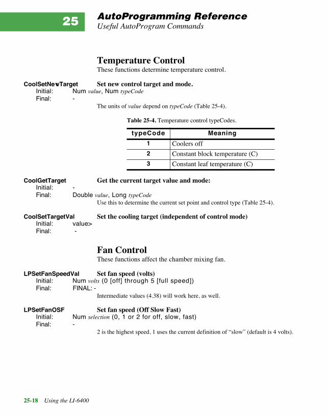
AutoProgramming ReferenceUseful AutoProgram Commands
25-18 Using the LI-6400
25
Temperature ControlThese functions determine temperature control.
CoolSetNewTarget Set new control target and mode.Initial: Num value, Num typeCodeFinal: -
The units of value depend on typeCode (Table 25-4).
CoolGetTarget Get the current target value and mode:Initial: -Final: Double value, Long typeCode
Use this to determine the current set point and control type (Table 25-4).
CoolSetTargetVal Set the cooling target (independent of control mode)Initial: value>Final: -
Fan ControlThese functions affect the chamber mixing fan.
LPSetFanSpeedVal Set fan speed (volts)Initial: Num volts (0 [off] through 5 [full speed])Final: FINAL: -
Intermediate values (4.38) will work here, as well.
LPSetFanOSF Set fan speed (Off Slow Fast)Initial: Num selection (0, 1 or 2 for off, slow, fast)Final: -
2 is the highest speed, 1 uses the current definition of ÒslowÓ (default is 4 volts).
Table 25-4. Temperature control typeCodes.
typeCode Meaning
1 Coolers off
2 Constant block temperature (C)
3 Constant leaf temperature (C)

AutoProgramming ReferenceAutoPrograms and the Control Manager
Using the LI-6400 25-19
AutoPrograms and the Control ManagerDuring an AutoProgram, the control manager will be active while the com-mands LPMeasure and LPMeasureTilStable are being executed.
Interaction with Variable TrackingIt is advisable to avoid setting a control option to track a variable (describedin Variable Targets on page 7-5), and at the same time try to control it withAutoProgram commands. Consider the following example: Suppose we se-lect the lamp control option ÒQuantum FluxÓ, and make the target #-13 (ex-ternal quantum sensor). Then, we try to do a light curve. When each of theselected light targets is implemented in the light curve (by, for example, theLPSetLamp command) the quantum flux target will indeed be set to that val-ue, but sometime within the following 30 seconds, the control manager willreset the target to the external quantum sensor value.
Thus, the target-setting AutoProgram commands (listed below) will overridevariable tracking for up to 30 seconds, but after that the variable trackingtakes over.
Low Level Control ToolsThe control manager is defined as part of OPEN. However, there is a veryuseful library file that should be included in any LPL program designed to runindependently of OPEN that will be doing control related work. The file is/Sys/Lib/StdControls, and it provides several tools, including those documentedbelow.
General Control Functions
AbdOn Turns on the flow control board.Initial: -Final: -
This board must be on to control any of the analog or digital inputs or outputs. Usesdigital output dio_flowbd (0x0302).
AbdOff Turns off the flow control board.Initial: -Final: -
Counterpart of AbdOn.

AutoProgramming ReferenceLow Level Control Tools
25-20 Using the LI-6400
25
IsAbdOn Is flow control board ON?Initial: -Final: Long logic (1=yes, 0=no)
Returns the state of digital output dio_flowbd (0x0302).
Flow Control Functions
PumpOn Turns on the pump, sets speedInitial: -Final: -
The pump speed is set to the current value of pump_mv, a variable defined in/sys/lib/stdcontrols. The switch is digital output dio_pump (0x0300), and the speed isD/A channel da_pump (6).
PumpOff Turns off the pumpInitial: -Final: -
Unsets dio_pump.
IsPumpOn Is the pump running?Initial: -Final: Long logic (1=yes, 0=no)
Returns the state of the digital output dio_pump.
NullOnFlow Set flow control for constant flow.Initial: Num setPoint (mV)Final: -
Sets flow control circuit to null on flow meter signal, target value (mV) given by set-Point. This command unsets digital output dio_null (0x0001), and sets D/A channelda_null_set (0).
NullOnRH Set flow control for constant humidity.Initial: Num setPoint (mV)Final: -
Sets flow control circuit to null on water IRGA in the sample cell signal, set point giv-en on the stack. Digital output dio_null is set, and D/A channel da_null_set is set tothe target value.
IsRHNull Are we controlling on water (as opposed to flow)?Initial: -Final: Long logic (1=humidity control, 0=flow control)
Returns the state of digital output dio_null.

AutoProgramming ReferenceLow Level Control Tools
Using the LI-6400 25-21
GetNullTarget Returns the current null set point value (mV)Initial: -Final: Double setPoint (mV)
Returns the value of D/A channel da_null_set.
Mixer Control Functions
Co2MixerPowerOn Powers on the CO2 injection circuitInitial: -Final: -
OPEN does this once when it starts. This is NOT the function to use for turning themixer on and off. Use Co2MixerOn and Co2MixerOff for that, but leave the power on all thetime. Uses digital output dio_inject (0x0000).
Co2MixerPowerOff Powers off the CO2 injection circuitInitial: -Final: -
See comments above.
Co2MixerOn Sets solenoid to allow CO2 injectionInitial: -Final: -
The flow of pure CO2 is switched into the flow circuit. Uses digital output dio_co2(0x0303).
Co2MixerOff Sets solenoid to bypass CO2 injectionInitial: -Final: -
The flow of pure CO2 is switched out of the flow circuit, so no mixing takes place.
IsCo2MixerOn Is CO2 mixing enabled?Initial: -Final: Long logic (0=mixer off, 1=mixer on)
Returns the state of the digital output dio_co2.
SetCo2MixerMv Set the CO2 mixer control voltage (0 to 5000 mV)Initial: Num setPoint (mV)Final: -
Converting µmol mol-1 to mV takes place at a higher level. Sets D/A channelda_co2_set (1).

AutoProgramming ReferenceLow Level Control Tools
25-22 Using the LI-6400
25
GetCo2MixerMv Get the CO2 mixer target voltage (mV)Initial: -Final: Double setPoint (mV)
Returns the current value of D/A channel da_co2_set.
Cooler Control Functions
CoolFan_on Turns on cooler, and sets cooling fan to full speed.Initial: -Final: -
Sets digital output dio_cool (0x0004), and D/A channel da_cool_fan to 5 V (fullspeed).
CoolFan_off Turns off cooler and cooling fan. Initial: -Final: -
Unsets digital output dio_cool (0x0004), and D/A channel da_cool_fan to 0 V.
Cooling Are coolers on?Initial: -Final: Long Logic (0=off, 1=on)
Returns state of digital output dio_cool.
Cooling_setpt Sets block cooling set point (C)Initial: Num temp (C)Final: -
Sets D/A channel da_chamber_temp (4).
Lamp Control Functions
SetLamp_mv Sets the lamp control value (0 - 5000 mV)Initial: Num setPoint (mV)Final: -
If mV is 0, lamp is turned off by unsetting digital output dio_lamp (0x0005). Other-wise, the digital output is set, and the D/A channel da_lamp (2) is set to the target val-ue.
GetLamp_mv Returns the current lamp control value (mV).Initial: -Final: Double setPoint (mV)
Returns the state of D/A channel da_lamp.

AutoProgramming ReferenceLow Level Control Tools
Using the LI-6400 25-23
IsLampON Is the lamp on?Initial: -Final: Long logic (0=off, 1=on)
Returns the state of digital output dio_lamp.
IRGA Control Functions
IrgaOn Turns on analyzer board.Initial: -Final: -
This board must be on to operate the IRGAs. This function sets digital outputdio_irgabd (0x0301).
IrgaOff Turns off analyzer board.Initial: -Final: -
Unsets digital output dio_irgabd.
IsIrgaOn Is analyzer board ON?Initial: -Final: Long logic (0=off, 1=on)
Returns state of digital output dio_irgabd.
StatusH2O Returns the status of the water IRGAsInitial: -Final: Long status (1=ok, 2=bad ref, 3=bad sample, or 4=both ref and sample)
This information comes from 2 digital inputs: dio_h2o1 and dio_h2o2 (0x0200 and0x0201).
StatusCO2 Returns the status of the CO2 IRGAsInitial: -Final: Long status (1=ok, 2=bad ref, 3=bad sample, or 4=both ref and sample)
This information comes from 2 digital inputs: dio_co21 and dio_co22 (0x0202 and0x0203).
IrgaMatchOn Turn on the IRGA matching valve.Initial: -Final: -
Unsets digital output dio_match (0x0007).
IrgaMatchOff Turn off the IRGA matching valve.Initial: -Final: -
Sets digital output dio_match (0x0007).

AutoProgramming ReferenceLow Level Control Tools
25-24 Using the LI-6400
25
IsIrgaMatch Is the match valve in the match position?Initial: -Final: Long location (0=normal, 1=match)
Returns the state of dio_match, but NOTted.
Chamber Fan Control Functions
ChFanState Sets chamber fan speedInitial: Num speed (0, 1, 2, 3, 4, or 5)Final: -
0 is off, 5 is fastest. Value is stored in a public, integer variable chFanState. Non zerovalues (and values <= 5) will cause digital output dio_fan (0x0006) to be set, and D/Achannel da_chamber_fan (7) to be set to 1000 times the speed. Otherwise, dio_fan isunset.
Example: Using the LibraryAs an example of how to use the tools in /Sys/Lib/StdControls, consider the stand-alone program shown in Figure 25-4. This program prompts the user for acommand voltage, and then sets the lamp accordingly.
:INCLUDE Ò/Sys/Lib/StdControlsÓ:FCT main{0 :FLOAT x
AbdOn /* need flow control board on */LOOPÒ\nEnter command signal (0-5000):Ó PRINT&x Ò%fÓ KBD ENTER NOT BREAKIF&x 0 MAX 5000 MIN DROP /* range check */x SetLamp_mv
ENDLOOP}
Figure 25-4. Listing of a stand alone program to run the lamp.

Using the LI-6400 26-1
26Customizing Open
ÒCry ÔHavocÕ - and let slip the dogs of warÓ
USING PATCH= 26-2
USEFUL VARIABLES 26-4A/D Measurements 26-4New Measurements 26-5Data Logging 26-6
OPENÕS HOOKS 26-7Example #1: Using New MeasurementÕs Fct Keys 26-9Example #2: Periodic Actions 26-11Example #3: Hooks in AutoPrograms 26-12
NEW STYLE COMPUTELIST FILES 26-16The userList Pointer Array 26-18Soil Flux Example 26-20
USING SPARE CHANNELS 26-22Analog Input Channels 26-22Analog Output Channels 26-23Digital Output 26-25Digital Input 26-26Pulse Counting 26-27Summary of the ConsoleÕs 37 Pin Connector 26-27

Customizing Open
26-2 Using the LI-6400
26This chapter explores some of the ways that you can modify OPEN to suityour purposes. The fact that it is the last chapter in the manual implies that thethings that have come before, especially involving programming in LPL,should not be totally foreign to you.
Using PATCH=A simple method of modifying OPEN is through the Configuration EditorÕsPatch= command. This method is best suited for modifying a system variablethat you otherwise do not have access to. The section New Style Com-puteList Files on page 26-16 lists a number of these variables and what theycontrol.
■■■■ How to add a Patch= command to a configuration file
1 Access the Config EditorIn the Config Menu, select "Config Status", then press Edit (f1).
2 Add a dummy line, or select a blank linePut the cursor where you want the new line, press Add, and select the"AREA= 6" entry.
3 Make the line a commentHighlight the new line, an press labels then Disable (f1).
4 Edit the commented linePress labels, then Edit (f1). Press DelLn (f1), and type
Patch=
followed by a space, and the command(s) you wish to do. For example, if youwish to set the digital output on pin 7 (0x0405) high, type
Patch= 1 0x0405 DIOSET
Press enter to end the editing.

Customizing OpenUsing PATCH=
Using the LI-6400 26-3
5 Remove the commentsPress labels, then Enable (f2), and the comment (//) will be removed from thefront of your patch command.
Table 26-1 lists a number of examples of patch command uses.
There are limits to what you can do with this method, however. You can onlychange a variable that is already defined (and PUB), and it only happens whenthe configuration file is actually processed. The section OpenÕs Hooks onpage 26-7 describes more powerful method for modifying OPEN.
Table 26-1. Samples of Patch= commands, and what they do.
Patch= Description
3500 3 AOSETa
a.The entire configuration line would be Patch= 3500 3 AOSET.
Sets analog output 3 (pin 12) to 3500 mV
0 &logBeepTime = Turn off log beeping
200 &logBeepTime = Make log beeps 0.2 seconds long
1 0x0401 DIOSET Set digital output (pin 5) low.
1 &compEvery = User values computed (and display updat-ed) every other time new readings are available.
"115200 8 2 N" COMMCONFIG Sets comm port configuration

Customizing OpenUseful Variables
26-4 Using the LI-6400
26
Useful Variables
A/D MeasurementsTable 26-2 lists some variables that pertain to how the LI-6400 makes analogmeasurements in New Measurements mode.
Table 26-2. Variables defined in /sys/open/open.a2d that are useful for modifying theA/D behavior.
Name Type Valuea
a.DonÕt change it if itÕs shaded!
Description
lowResGroup INT0
Group number for all non-IRGA chan-nels
hiResGroup INT 1 Group number for all IRGA channels
groupQueue INT 1 Buffer size for accumulating readings
hiResUpdateTime FLOAT
.75Update time. New readings available every __ seconds. (Low and Hi resolu-
tion channels both use this period.)
hiResCount INT 16 Number of raw readings per update time. lowResCount INT 4
hiResAvgTime FLOAT 2b
b.Also set by the AvgTime= configuration command.
Running average periods (secs).lowResAvgTime FLOAT 1

Customizing OpenUseful Variables
Using the LI-6400 26-5
New MeasurementsThere are some variables that you can use to define function keys in NewMeasurements mode, or to change how often user computations are done(Table 26-3).
Table 26-3. Useful New Measurements variables, defined in /sys/open/open.msr
Name Type Valuea
a.DonÕt change it if itÕs shaded!
Description
ukey1, ukey2, ukey3, ukey4, ukey5
INT 31É35 Use for defining the five user defined function keys.
maxKeys INT 35 Determines max # of function keys in New Msmnts mode.
compEvery INT 2 Determines how often user computations are done. 0 = every time new measure-ments are available,1 = every other time2 = every 3rd time, etc.
matchStableLimit FLOAT 2 CO2 range limit (ppm) for de-termining ÒstabilityÓ when auto-matching (during an Au-toProgram).
matchAutoTimeLimit INT 60 How long (secs) to wait for stability during auto-matching.

Customizing OpenUseful Variables
26-6 Using the LI-6400
26
Data LoggingSome variables pertaining to logging are presented in Table 26-4.
Table 26-4. Useful New Measurements variables, defined in /sys/open/open.log
Name Type Valuea
a.DonÕt change it if itÕs shaded!
Description
logBufferOpen INT 0 or 1 0=logging inactive1=logging active. (Do not set this variable!)
logBeepTime INT 200 Duration of beep when log-ging, in milliseconds.
obsInPad INT 0 Number of observations logged since destination opened. (System variable, #-35)
obsOneTime Long 0 Time and date (seconds) des-tination was opened.

Customizing OpenOpenÕs Hooks
Using the LI-6400 26-7
OpenÕs HooksOPEN provides extended control to users via a series of hooks. What is ahook? Suppose that you want the LI-6400 to print a CO2 value to the RS-232port (or any other task) every 1 second while in New Measurements mode.Happily, there are some things that OPEN has to do every second, and sothere is a function that is called with that frequency. Happier still, you cansubstitute your own function for it. This ability to substitute at strategic pointsis what hooks provide.
There are two approaches to take to make use of a hook.
1 Add a function with a ÒspecialÓ name to a ComputeList.The safest way to take advantage of OPENÕs hooks is put one or more
:include fileName
directive(s) into your ComputeList file that will link module(s) containingfunctions to do the activities that you want. The names of these functions arevery important, and Table 26-5 lists the required name along with what thedefault actions are.
Before a ComputeList is processed, all of these hooks are reset to default val-ues (thatÕs what makes this safe). Once a ComputeList is implemented,OPEN looks for functions in the ComputeList module whose names matchthe hook names. Each one found is substituted for the default function.
2 Direct pointer manipulationA second method of using these hooks is to manipulate the hook directly, byreassigning the pointer associated with the hook. The relevant pointer namesare also shown in Table 26-5.

Customizing OpenOpenÕs Hooks
26-8 Using the LI-6400
26
Table 26-5. OPENÕs Hooks
Pointer Name When Called Normally Points to Looks for Name
HookUserKeys Called in New Measurements mode after defining all the other function keys.
:FCT Nothing { } DefUserKeys
HookNewReadings Called in New Measurements mode right after new A/D readings are available (ev-ery 0.75 secs, by default), and Compute-Sensors has been called to compute all the measured quantities.
:FCT Nothing { } UserNewReadings
HookEverySec Called every 1 second during New Mea-surements mode.
:FCT EverySec{ LogFromButton UpdateClock CompStability}
UserEverySec
HookPreComps Called every 2.25 seconds prior to doing the User Computations.
:FCT CompPrep UserPreComps
HookPostComps Called every 2.25 seconds just after the User Computations.
:FCT Nothing { } UserPostComps
HookWatchDog Called every 10 seconds in New Mea-surements mode to check for problems (such as IRGA(s) Not Ready)
:FCT WatchDog UserWatchDog
HookNewMeasureStartup
Called each time New Measurements mode is entered.
:FCT StdNewMeasure-Startup
UserNMStartup
HookMainDisplay Called in OpenÕs main screen to put the top three lines on the display.
:FCT StdMainDisplay UserMainDisplay
HookCalibMenu Called from OpenÕs main screen in re-sponse to pressing the Calib Menu FCT key.
:FCT StdCalibMenu UserCalibMenu

Customizing OpenOpenÕs Hooks
Using the LI-6400 26-9
Example #1: Using New MeasurementÕs Fct KeysFigure 26-1 shows the module “LI-610 Fct Key”, and illustrates how hooks can beused to define function keys in OpenÕs New Measurements mode. The task athand is to provide a function key in New Measurements mode that will set aD/A channel for controlling an LI-610 Dew Point Generator. The functionkey will be on level 7 (which normally has 5 blank keys).
You can try this out by selecting Config Menu ® "Installation Menu" ®"Configuration Examples Menu" ® "LI-610 Fct Key Control". This willinstall a new configuration, and if you switch to it ("Reset to UserConfig"), youÕll see the new key in New Measurements mode, level 7.
DiscussionWe accomplish this task by using two hooks: DefUserKeys is the most impor-tant, since that is how weÕll get our key defined. The other hook, UserNM-
Figure 26-1. The file Ò/User/Configs/Modules/LI-610 Fct KeyÓ. It uses two hooks by defining the functionsDefUserKeys, and UserNMStartUp.
/*Module to control an LI-610with fct key 1, level 7 in New Measurements mode.
*/
/* --------- internal stuff ----------- */:STATIC 1:FLOAT targetDP 20.0
/* Uses D/A port number 3 That's pins 12 and 13 (signal and ground) on the 37 pin console connector.*/ :INT d2aPort 3
/* The variable ukey1 is the keynumberfor fct key 1, level 7Similarly, ukey2, ukey3, ukey4, and ukey5define the others
*/:FCT Def610Key{targetDP "Target= %g" to_string
&Change610Target ukey1 ONSOFT}
Change610Target{&StdFloatAssign "610 Target Temp (C)" "%g"
&targetDP AskNewFloatDef610Key SHOWSOFTSetThe610
}
SetThe610{targetDP 100 * d2aPort AOSET
}
/* --------- external stuff ------------- */
:STATIC 0:FCT/* HOOK: Called when defining New Measurements fct keys*/DefUserKeys{Def610Key
}
/* HOOK: Called when new measure mode entered*/UserNMStartup{SetThe610StdNewMeasureStartup
}

Customizing OpenOpenÕs Hooks
26-10 Using the LI-6400
26
Startup, is only used to set the LI-610 to the target temperature when NewMeasurements mode is first entered. If we didnÕt do this, the LI-610 wouldnot be set until the user presses the function key to set a target the first time(and perhaps that is desirable, but weÕre doing it for illustration purposes). Atany rate, the two external functions at the end of the module are our hooks.
DefUserKeys{Def610Key
}
UserNMStartup{SetThe610StdNewMeasureStartup
}
Notice that the UserNMStartup function call our function SetThe610, andthen calls itÕs normal function, StdNewMeasureStartup (see Table 26-5 onpage 26-8). ThatÕs important, because we donÕt normally want StdNewMea-sureStartup to be skipped.1
The function Def610Key uses ONSOFT to define the our key.
:FCT Def610Key{targetDP "Target= %g" to_string &Change610Target ukey1
ONSOFT}
The function to_string is a handy tool for building a temporary string, and isdefined in /sys/open/open.utl. Since ONSOFT requires a function key number, weuse ukey1, rather than 31 (f1 level 7 is 31, f2 is 33, etc.). ItÕs safest to use thevariables (defined in /sys/open/open.msr) ukey1, ukey2, ukey3, ukey4, and ukey5when defining New Measurements ÒemptyÓ keys, since the actual key num-bers may change in future releases, but the named constants will always becorrect.
How a module is usedOnce you have a module written, a good place to keep it is in/user/configs/modules. Then, anytime you want to add that functionality to aComputeList, simply add an ÒincludeÓ line to the top of the ComputeList file.In our example, the ComputeList that is active for the LI-610 configurationhas a line near the top of it that says
1.The soil flux configuration, on the other hand, uses this hook and purposefullyskips StdNewMeasureStartup.

Customizing OpenOpenÕs Hooks
Using the LI-6400 26-11
:include "/user/configs/modules/LI-610 Fct Key"
You could add that line to any ComputeList file, and thereby include theLI-610 function key feature.
Example #2: Periodic ActionsAs a second example of using OPENÕs hooks, weÕll make a module that trans-mits some data out the comm port at regular intervals. LetÕs suppose we wantCO2 reference and sample, and H2O reference and sample, and we want themoutput as often as we have new readings. And, this needs to work whether ornot an Autoprogram is running, or we are logging, etc.
The hook we want is UserNewReadings, since that is called each time wehave new measured values. The only other thing we need is the variablenames of the four quantities (see Table 14-8 on page 14-19). The module isshown in Figure 26-2.
To use this, store it in the /user/configs/modules directory, and include it inwhatever ComputeList you wish. A useful addition to this module would bea function key for turning this transmission on and off. We leave that as anexercise for the reader, as math texts are prone to say.
/*
IRGA data -> comm port
*/:PTR list[] { co2_1_um co2_2_um h2o_1_mm h2o_2_mm }:CHAR format[] "%6.1f %6.1f %6.2f %6.2f\n":FCT UserNewReadings{
list format COMM PRINT}
Figure 26-2. Module to transmit IRGA values out the comm port. Data issent as it becomes available.

Customizing OpenOpenÕs Hooks
26-12 Using the LI-6400
26
Example #3: Hooks in AutoProgramsThe AutoProgram ÒAveraging AutoLogÓ (described on page 9-23) providesa useful example of what can be done with hooks from with an AutoProgram.In this case, since our changes are confined to the time the AutoProgram runs,weÕll manipulate the hooks directly, rather than by using the magic functionnames.
Here are the interesting behavior modifications that this AutoProgram does:
1 Temporarily reassign the UserNewReadings hook
2 Slow down how often measurements are madeChange it from 0.75 seconds, to 1.5 seconds.
3 Speed up how often calculations are doneChange it from every 2.25 seconds, to 1.5 seconds. Thus, computations aredone at the same rate as measurements are being made.
The listing of ÒAveraging AutoLogÓ follows, with some margin notes.
/*
AutoLog with Averaging
for OPEN version 3
To log the number of readings in each average, include'auxN3' (sys value -106) in the log list.
*/
:FLOAT totals[100] { }totalDuration 60readingsEvery 1.5 /* secs */
:INT logInterval 30numAdded 0numLogged 1matchAfter 0matchCount 0minAvgTime 30delayTime 0skipThese[] { -35 -36 }
:LONG stopTime 0:CHAR progName[] "AvgAutoLog"defaultFile[] "AvgAutoLog Dflts"
:PTR user[] { :PTR { logInterval "Log (and average) interval (sec)="}:PTR { totalDuration "Quit after (minutes)="}:PTR { matchAfter "MATCH every Nth Log (0 = never)="}}

Customizing OpenOpenÕs Hooks
Using the LI-6400 26-13
actionList[100] { }
:FCT main{progName LPSetName
CLEAR"AutoLog with Averaging\n" PRINT"(Note: To log the number of readingsaveraged for each obs, include 'auxN3'(sys value -106) in the log list.)\n\n" PRINT
defaultFile user LPPrompts2 IF RETURN THEN
BuildActionList
LPPrep
/* Hook the hook*/
Reassign the pointer HookNewReadings.
&HookNewReadings PVAL :PTR oldFct&MyActivity &HookNewReadings =
/* New readings less often,all comps and screen updates done with each one.*/
Change update times. hiResUpdateTime :FLOAT oldUpdatecompEvery :INT oldComp
readingsEvery &hiResUpdateTime =0 &compEvery =A2dProgram
GETMS totalDuration 60000 * + &stopTime =matchAfter &matchCount =2 LPMeasure
LOOPstopTime GETMS - 1000 / logInterval / :INT nnumLogged DUP n + SWAP LPSetProgress
logInterval LPMeasure
ComputeMeansAndLoglpAbort BREAKIF
matchAfter IF&matchCount 1 - VAL 0 <= IFLPMatchmatchAfter &matchCount =THENTHENENDLOOP
/* Restore A2d behavior*/
This is important! If you don’t do it, no one else will.
oldUpdate &hiResUpdateTime =oldComp &compEvery =A2dProgram

Customizing OpenOpenÕs Hooks
26-14 Using the LI-6400
26
/* Restore the hook*/
This is also important. oldFct will go away, but HookNewReadings doesn’t.
&oldFct &HookNewReadings =
LPCleanup}
This Fct is called each time new measurements are available.
MyActivity{UpdateTotalGETMS stopTime > IF1 &lpAbort =HALTTHEN}
The remaining functions are involved with the data averaging.
UpdateTotal{/* update values */
1 :INT i
actionList READY NLOOPtotals i PICK actionList i PICK VAL + DROP&i 1 + DROPENDLOOP&numAdded 1 + DROP
}
ComputeMeansAndLog{numAdded NOT IF RETURN THEN
actionList READY :INT n
totals n SETREADYtotals numAdded / DROP
1 :INT i n NLOOPtotals i PICK VAL actionList i PICK =&i 1 + DROPENDLOOPnumAdded &auxN3 =LPLog0 &auxN3 =0 &numAdded = 0 totals =&numLogged 1 + DROP}
BuildActionList{1 :INT i
"xx" TYPE SWAP DROP :INT stringType
userLogList READY NLOOP

Customizing OpenOpenÕs Hooks
Using the LI-6400 26-15
userLogList i PICK VAL :INT idskipThese id FIND NOT IFlogVariableList i PICK PVAL TYPE stringType <> IFactionList APPTHENTHEN&i 1 + DROPENDLOOP}
Using HookNewReadingsIn order to record averaged data, the AutoProgram must be able to updatethese averages as each new set of readings becomes available. The HookNe-wReadings pointer is saved, and redirected to our own function (MyActivity)to do this work. If we wanted to preserve the old HookNewReadings activitywhile this program runs, we could add a call to oldFct somewhere in MyAc-tivity.
It is very important to restore HookNewReadings to itÕs original value beforethe AutoProgram ends. If we donÕt, HookNewReadings will be pointing at ablock of deallocated memory, and will likely crash OPEN the next time it getscalled.
Changing Update TimesThe ÒAveraging AutoLogÓ program also modifies the way the A/D converterruns, and when user computations are performed. It does this simply bychanging two variables, then restarting the A/D (with a call to A2DProgram).Again, the original values are preserved, and the A/D reprogrammed at theend of the AutoProgram. See Table 26-2 on page 26-4, and Table 26-3 onpage 26-5.

Customizing OpenNew Style ComputeList Files
26-16 Using the LI-6400
26
New Style ComputeList FilesComputeLists (Chapter 15) are a collection of definitions of variables that theuser can define. This definition file (example, Figure 26-3) is converted intoa file written in LPL that can be linked to OPEN (Figure 26-4 on page 26-17).
ComputeLists can be written in either format. The Òold styleÓ (Figure 26-3)or the Ònew styleÓ (Figure 26-4). The advantage of the new style is that youhave direct control over everything, so the customization possibilities areendless.
To help you take advantage of this style, there is a utility for generating a newstyle ComputeList from an old style; it is found in the "ComputeList Menu"entry in the Config Menu.
##10 "(U/S)" "flow:area ratio" " flow_um / area_cm2 / 100.0"
##20 "Trans" "Transpiration (mol/m2/s)" " #10 * (h2o_2_mm - h2o_1_mm) / (1000.0 - h2o_2_mm)"
##21 "Trmmol" "Transpiration (mmol/m2/s)" " #20 * 1E3"
##23 "Cond" "Stomatal cond. (mol/m2/s)" " StdCond(#20, Tleaf_c, condBL_mol, press_kPa, h2o_2_mm)"
##30 "Photo" "Photosynthesis (umol/m2/s)" " -#10 * co2_diff_um - co2_2_um * #20"
##35 "CndCO2" "Total Conductance to CO2" " 1.0 / (1.6 / #23 + 1.37 / condBL_mol)"
##36 "Ci" "Intercellular CO2 (umol/mol)" " ((#35 - #20/2) * co2_2_um - #30) / (#35 + #20/2)"
##38 "Ci_Pa" "Intercellular CO2 (Pa)" " #36 * press_kPa * 1E-3"
##39 "Ci/Ca" "Intercellular CO2 / Ambient CO2"" #36 / co2_2_um "
##25 "VpdL" "Leaf VPD (es(Tleaf) - eair)"" SatVap(Tleaf_c) - eAir_2_kPa"
##27 "VpdA" "Air VPD (es(tair) - eair)"" satVapTair_kPa - eAir_2_kPa"
Figure 26-3. Listing of file /User/Configs/Comps/Default

Customizing OpenNew Style ComputeList Files
Using the LI-6400 26-17
/* Converted from
/user/configs/comps/Default
Mon Dec 29 1997 14:41:11*/
:STATIC 1:CHAR s8[] "%8s":DOUBLE u10 0u20 0u21 0u23 0u30 0u35 0u36 0u38 0u39 0u25 0u27 0:STATIC 0
:PTR userList[]{ :PTR { 10 "(U/S)" s8 u10 g83 "flow:area ratio" 0 g13 } :PTR { 20 "Trans" s8 u20 g83 "Transpiration (mol/m2/s)" 0 g13 } :PTR { 21 "Trmmol" s8 u21 g83 "Transpiration (mmol/m2/s)" 0 g13 } :PTR { 23 "Cond" s8 u23 g83 "Stomatal cond. (mol/m2/s)" 0 g13 } :PTR { 30 "Photo" s8 u30 g83 "Photosynthesis (umol/m2/s)" 0 g13 } :PTR { 35 "CndCO2" s8 u35 g83 "Total Conductance to CO2" 0 g13 } :PTR { 36 "Ci" s8 u36 g83 "Intercellular CO2 (umol/mol)" 0 g13 } :PTR { 38 "Ci_Pa" s8 u38 g83 "Intercellular CO2 (Pa)" 0 g13 } :PTR { 39 "Ci/Ca" s8 u39 g83 "Intercellular CO2 / Ambient CO2" 0 g13 } :PTR { 25 "VpdL" s8 u25 g83 "Leaf VPD (es(Tleaf) - eair)" 0 g13 } :PTR { 27 "VpdA" s8 u27 g83 "Air VPD (es(tair) - eair)" 0 g13 }}
:FCT ComputeUserValues{ $ u10 = flow_um / area_cm2 / 100.0 u20 = u10 * (h2o_2_mm - h2o_1_mm) / (1000.0 - h2o_2_mm) u21 = u20 * 1000 u23 = StdCond(u20, Tleaf_c, condBL_mol, press_kPa, h2o_2_mm) u30 = -u10 * co2_diff_um - co2_2_um * u20 u35 = 1.0 / (1.6 / u23 + 1.37 / condBL_mol) u36 = ((u35 - u20/2) * co2_2_um - u30) / (u35 + u20/2) u38 = u36 * press_kPa * 1E-3 u39 = u36 / co2_2_um u25 = SatVap(Tleaf_c) - eAir_2_kPa u27 = satVapTair_kPa - eAir_2_kPa}
Figure 26-4. The ComputeList ÒDefaultÓ, converted to New Style.
Declaration Section
List of user variables, and attributes
Computation Section

Customizing OpenNew Style ComputeList Files
26-18 Using the LI-6400
26
The new style consists of a declaration section, in which all user variables aredefined. There is a computational section, which is the function (named Com-puteUserValues) that is called each time user values are to be computed. Themiddle section, the declaration of a pointer array named userList, requires abit of explanation.
The userList Pointer ArrayThe pointer array named userList contains one object for each user variableor constant that is defined. (These are the items with ID numbers greater thanzero that appear at the top of the selection list that you see when building dis-plays or Log Lists, for example). Each item in the pointer array is itself apointer that must contain 8 items (Figure 26-5), and optionally a 9th item(Table 26-6).
Figure 26-5. The elements of each :PTR array that make up userList[].
:PTR { 10 "(U/S)" s8 u10 g83 "flow:area ratio" 0 g13 }
ID #
Display Label
Log Label (or 0 if same as Display Label)
Display Label Format String
Display Format String
The Variable The Description Log Format String
Table 26-6. Descriptions Of The Elements In Each userList[] Entry
# Name Description
1 ID# Any integer 1...32767
2 Display Label This should be no more characters than you wish the display length to be (typically 8).
3 Display Label Format String
For New Measurements mode. Typically something like Ò%8sÓ. This is the mechanism by which a short label is made to take up the requisite number of spaces.
4 The Variable The variable name. Must be defined somewhere, as a :FLOAT, or :INT, etc.

Customizing OpenNew Style ComputeList Files
Using the LI-6400 26-19
Some format strings are defined in OPEN.DF2, since they are used in the sys-tem variable definitions (system variables are defined with a similar :PTR ar-ray). If you refer to Table 15-1 on page 15-5, you will see some displayformats that can be specified in the old style Compute List. The actual formatstring used for display and logging is shown in Table 26-7 below.
5 Display Format String The format string that determines how the value of the variable is dis-played in New Measurements mode. This is typically a string like Ò%8.1fÓ or Ò%8.3GÓ, etc. The variable g83 is defined in OPEN.DF2 and is the string Ò%8.3GÓ
6 Description Any descriptive (or vague and confusing, if you prefer) string.
7 Log Label The label that will be printed in the log file, should this variable ever be included in a Log List. If you wish to use the display label for this, just enter a numeric value, like 0, instead of a string.
8 Log Format String The format you wish used for the variable if it is logged. Note that while you may display a number with something like Ò%8.1fÓ, you may not want to consume 8 spaces all the time when you log, so you would use the corresponding Ò%1.1sÓ.
9 (Optional) Can be nothing, or 1, or 2:1. A user defined constant, that should be included automatically in the active Prompt List.2. A user defined constant that should not be automatically included in the active Prompt List.
Table 26-6. (Continued) Descriptions Of The Elements In Each userList[] Entry
# Name Description
Table 26-7. Relation Between Old Style Format Codes and Actual Format Stringsa
a. Not all are shown, but enough to give you the idea.
Old Style Format Code
Display Format Used Logging Format Used
Variable Name
String Variable Name
String
F0 f80 Ò%8.0fÓ f10 Ò%1.0fÓ
F5 f85 Ò%8.5fÓ f15 Ò%1.5fÓ
G1 g81 Ò%8.1fÓ g11 Ò%1.1GÓ
G6 g86 Ò%8.6fÓ g16 Ò%1.6GÓ

Customizing OpenNew Style ComputeList Files
26-20 Using the LI-6400
26
Soil Flux ExampleHereÕs a listing of the ComputeList used for the 6400-09 Soil Flux Chamberwhen used in closed mode. This file is stored in “Configs/Comps/Soil EffluxEqns.LPL”.
:INCLUDE Ò/sys/Closed/Soil Efflux ToolsÓ:INT sad 0:CHAR df3g[] Ò%8.3GÓ df4g[] Ò%8.4GÓ df8d[] Ò%8dÓ df2f[] Ò%8.2fÓ df1f[] Ò%8.1fÓ lf3g[] Ò%1.3GÓ lf4g[] Ò%1.4GÓ lf5g[] Ò%1.5GÓ lf1d[] Ò%1dÓ lf2f[] Ò%1.2fÓ lf1f[] Ò%1.1fÓ s8[] Ò%8sÓ
Notice, most of the variables in the userList array are defined in the “soil efflux tools” module that is included.
:PTR userList[]{ :PTR { 300 ÒdC/dtÓ s8 co2Slope df3g ÒdC/dt (æmol/s)Ó sad lf5g } :PTR { 301 ÒdW/dtÓ s8 h2oSlope df3g ÒdW/dt (mmol/s)Ó sad lf5g } :PTR { 302 ÒC2avgÓ s8 co2Mean df1f ÒMean CO2 (æmol/s)Ó sad lf1f } :PTR { 303 ÒWavgÓ s8 h2oMean df2f ÒMean H2O (mmol/s)Ó sad lf2f } :PTR { 304 ÒVtotÓ s8 soilChamSysVol df4g ÒTotal volume (cm3)Ó sad lf4g }
“InsDepth” is a user defined constant.
:PTR { 305 ÒInsDpthÓ s8 soilInsDepth df3g ÒInsertion Depth (cm)Ó sad lf3g 2 } :PTR { 306 ÒdcÕ/dtÓ s8 dcdt df3g Òrate of change of co2 densityÓ sad lf4g } :PTR { 307 ÒVbaseÓ s8 soilChamBaseVol df4g Òvol (cm3) at 0 depthÓ sad lf4g 2 } :PTR { 310 ÒModeÓ s8 opMode df8d Ò0-4Ó sad lf1d } :PTR { 311 ÒSmplsÓ s8 numSamps df8d Ò# obs of slopes or efflux ratesÓ sad lf1d } :PTR { 312 ÒProgram StatusÓ Ò%-18sÓ srState Ò%-18sÓ ÒStatusÓ ÒPgStsÓ Ò%-18sÓ } :PTR { 313 ÒTargetÓ s8 targetCO2 df8d ÒTarget CO2 æmol/molÓ sad lf1d 2 } :PTR { 314 ÒDeltaÓ s8 deltaCO2 df8d ÒCO2 Delta æmol/molÓ sad lf1d 2 } :PTR { 315 ÒddMarginÓ s8 ddSafetyMargin df8d ÒExtra DrawDown (ppm)Ó sad lf1d 2 } :PTR { 316 ÒDeadTimeÓ s8 postPumpDeadSecs df8d ÒDeadTime (secs)Ó sad lf1d 2 } :PTR { 317 ÒMnMsrTmeÓ s8 minMeasureTime df8d ÒMin Measure Time (secs)Ó sad lf1d 2 } :PTR { 318 ÒNumCyclsÓ s8 numCycles df8d ÒNumber of CyclesÓ sad lf1d 2 } :PTR { 320 ÒEFFLUXÓ s8 soilEfflux df3g ÒCO2 Efflux umol/m2/sÓ sad lf3g } :PTR { 321 ÒRHcmbr%Ó s8 rhsc df2f ÒRH in soil chamber %Ó sad lf2f} :PTR { 322 ÒTsoil_CÓ s8 tSoil df2f ÒSoil Temp CÓ sad lf2f} :PTR { 323 ÒRHirga%Ó s8 rhOut df2f ÒIRGA RHÓ sad lf2f } :PTR { 324 ÒTsch_CÓ s8 tLeaf_c df2f ÒSoil Chamber Air Temp CÓ sad lf2f } :PTR { 330 ÒR(C)mÓ s8 dcdtSlope df3g ÒSlope of dcÕ/dt vs CO2Ó sad lf5g } :PTR { 331 ÒR(C)bÓ s8 dcdtOffset df3g ÒOffset of dcÕ/dt vs CO2Ó sad lf5g }

Customizing OpenNew Style ComputeList Files
Using the LI-6400 26-21
}
/* Called from recomp program, or open, every time user vals are to be computed*/:FCT ComputeUserValues{ 0 :FLOAT density 0 :FLOAT va $ rhsc = 100.0 * eAir_2_kPa / SatVap(Tleaf_c) tSoil = chan21_mv / -10.0 soilChamSysVol = soilChamBaseVol - area_cm2 * soilInsDepth va = soilChamSysVol / area_cm2 IF (opMode == 3) density = press_kPa * 1.2028 / (tleaf_c + 273) dcdt = density * (co2Slope - co2Mean * h2oSlope / (1000.0 - h2oMean)) THEN IF (opMode == 4) dcdt = dcdtSlope * co2Mean + dcdtOffset THEN soilEfflux = dcdt * va}

Customizing OpenUsing Spare Channels
26-22 Using the LI-6400
26
Using Spare Channels
Analog Input ChannelsFour spare analog input channels are available for use (Table 26-8):
Measurements are referenced to a ground signal that is software selectable(Table 26-9). All of the LI-6400Õs analog inputs are over voltage protected to±35V, with or without power.
ConnectionsTo wire an analog input, select a signal pin (Table 26-8) and a ground pin(Table 26-9).
SoftwareOPEN takes care of the details of programming for the spare analog inputchannels. All you have to do is add the UserChan= configuration commandto the configuration file, and edit it so that it reflects the signal and groundchannels being used by the sensor. Choose the resolution (high or low). Achannel measured with high resolution is sampled at the same rate as the gasanalyzers, and is subject to the AvgTime= configuration command. Signalsmeasured with low resolution have a 1 minute average time.
Table 26-8. User define analog input channels.
LPLID#
Pin #(37 Pin Connector)
Range(V)
Resolution(mV)
20 36
-5 to +50.27 (low)0.06 (high)
21 19
22 18
23 37
Table 26-9. Ground channels for analog input signals
LPLID#
Pin #(37 Pin Connector) Also used for
3 31 Chamber signals
4 14 Pressure sensor
5 32
6 15
7 17

Customizing OpenUsing Spare Channels
Using the LI-6400 26-23
For a general discussion of analog input programming, see Analog Measure-ments on page 23-66.
Analog Output ChannelsSix digital to analog output channels are available for use (Table 26-10).
ConnectionsUse pin 13 as the ground for these outputs.
SoftwareAn analog output is controlled with the LPL command AOSET. (This and re-lated commands are discussed in Analog Output Control (D/A) on page23-73.) There are a number of ways to update an analog output signal, and afew examples are listed below. Which method you use depends on how oftenyou wish to have the signal updated.
¥ Once at the start of OPENThis is probably most easily done by inserting a PATCH= command into theconfiguration file. This will execute every time that configuration is imple-mented. For example, suppose you need to provide 4 volts to some device aspart of a particular configuration. If you are using channel 10 for this, youwould add
PATCH= 4000 10 AOSET
to your configuration file. That will set analog output channel 10 to 4000 mV.
¥ Only when the user presses a function key and enters a new valueThis technique involves defining function keys in New Measurements mode.An example of doing this can be seen by installing the "LI-610 Fct Key
Table 26-10. Spare D/A channels.
LPLID#
Pin #(37 Pin Connector)
Range (V)
Resolution (mV)
Current(mA)
3 12 -5 to +5 2.44 ±5
9 270 to 5 19.5
+5 / -2
10 9
17 29
-5 to +5 3918 11
19 30
Customizing OpenUsing Spare Channels
26-24 Using the LI-6400
26
Control" example found in the "Configuration Examples Menu" in the"Installation Menu" of the Config Menu.
As a result of doing this installation, a module named Ò/User/Configs/Mod-ules/LI-610 Fct KeyÓ will be created (Figure 26-1 on page 26-9). You canmodify this module as needed to suit your purposes, and store it under a newname. To add your function key to any configuration, add the line
:include "/user/configs/modules/<name>"
to the ComputeList, where <name> is the name of your modified module.
¥ Every time user variables are computedA very easy way to update an analog output channel is to do it each time uservariables are computed (approximately every 2 or 3 seconds). For example,if you want to have an analog output that is proportional to photosyntheticrate, edit the ComputeList definition of photosynthesis to be
##30 "Photo" "Photosynthesis (umol/m2/s)""-#10*co2_diff_um - co2_2_um*#20AOSET(#30 * 5000.0 / 30.0, 3)
This uses D/A channel 3, and scales the signal so that 5V is 30 µmol m-2 s-1.
¥ Whenever you feel like it (no programming required)A simple method of setting a D/A channel is to do the AOSET manually fromthe keyboard. From OPENÕs main screen, press K to run the LPL Shell pro-gram. At the ok: prompt, type the command and press enter. For example,
ok:2450 3 AOSET
will set channel 3 to 2450 mV. Press escape to leave this mode.
¥ In an AutoProgramIf the D/A is to be controlled only when a particular AutoProgram is running,then that can simplify the programming. The control can be set at the start ofthe AutoProgram, or, if frequent updates are necessary, the control can be up-dated once each second during the AutoProgram. See Example #3: Hooks inAutoPrograms on page 26-12.

Customizing OpenUsing Spare Channels
Using the LI-6400 26-25
Digital OutputSeveral digital channels are available for use (Table 26-11):
ConnectionsUse pin 20 for the digital ground. These open drain digital outputs require theuse of an external pull-up resistor. When the digital line is set high, the volt-age will go to 0, and when it is set low, it will go to whatever voltage you haveon the other side of the resistor (Figure 26-6.
SoftwareUse the DIOSET command. (This and related commands are discussed inDigital I/O on page 23-75.) For example,
1 0x0402 DIOSET0 0x0401 DIOSET
will set 0x0402 high (0V), and 0x0401 low (5V, if using pin 1 for voltage sup-ply).
Table 26-11. Spare digital channels.
LPLID#
Pin #(37 Pin Connector)
LPLID#
Pin #(37 Pin Connector)
0x0400 23 0x0404 25
0x0401 5 0x0405 7
0x0402 24 0x0406 26
0x0403 6 0x0407 8
5 V (pin 1)
Digital Ground (pin 20)
Digital Output (pin 5)
10K Ohm
Figure 26-6. To connect a digital output, use a 10K resistor between the outputpin and the 5V supply, and measure the voltage between the output pin and dig-ital ground. When the output is set (high), youÕll measure 0 volts between pins5 and 20, and when not set (low), youÕll measure 5 volts.

Customizing OpenUsing Spare Channels
26-26 Using the LI-6400
26
Digital InputTwo digital input channels are available, besides the log switch.(Table 26-11):
These inputs can be used to detect switch closures or to count pulses (provid-ed they are slow - less than about 10Hz).
ConnectionsUse pin 20 for the digital ground. Digital input signals should be kept between0 and +5 volts. Figure 26-7 illustrates a method of connecting a switch.
SoftwareFor detecting the position of the switch, use DIOGET.
0x0106 DIOGET
It will return 1 if the input is high, and 0 if the input is low. An input channelcan be used to count pulses (<10 Hz), and this is discussed in Digital I/O onpage 23-75. (For higher frequency pulse counting, see High Speed Counteron page 23-76.)
The question of where one does the programming arises: it depends on howoften you need to check the digital input. You might want to include this in aComputeList, or an AutoProgram, or do it every second in New Measure-
Table 26-12. Spare digital channels.
LPLID#
Pin #(37 Pin Connector)
0x0106 4
0x0107 22
5 V (pin 1)
Digital Ground (pin 20)
Digital Input (pin 4)
10K Ohm
Figure 26-7. To connect a digital input, use a 10K resistor between the inputpin and the 5V supply. When the switch is open, the digital input will be high,and when closed, the input will be low.
switch

Customizing OpenUsing Spare Channels
Using the LI-6400 26-27
ments mode.
Pulse CountingThe LI-6400 has one pulse counting channel, that can count pulses up toabout 4 KHz.
ConnectionsUse pin 20 for the digital ground, and pin 3 for the pulsed signal. A pulse iscounted each time the signal drops from >5V to 0. Figure 26-8 illustrates amethod of connecting a switch.
SoftwareUse the HSCOUNTS LPL keyword.
Summary of the ConsoleÕs 37 Pin ConnectorThe LI-6400 consoleÕs 37 pin connector assignments are listed inTable 26-13. The shaded entries (pins 10, 21, and 28) are outputs that arewired in parallel with some component in the LI-6400, and would not normal-ly be controlled by a user application.
Digital Ground (pin 20)
Pulse counting (pin 3)
Figure 26-8. To connect the pulse counting, use pins 3 and 20. Pulses shouldbe between 0 and (5 < x < 8) Volts.
pulsegenerator

Customizing OpenUsing Spare Channels
26-28 Using the LI-6400
26
Table 26-13. Summary of the consoleÕs 37 pin connector
Pin # Name Comments1 + 5V
2 Battery
3 Pulse Counting Input Pulse Counting on page 26-27
4 Digital Input 0x0106 Digital Input on page 26-26
5 Digital Output 0x0401
Digital Output on page 26-256 Digital Output 0x0403
7 Digital Output 0x0405
8 Digital Output 0x0407
9 Analog Output 10 (0 to 5V, 8 bit) Analog Output Channels on page 26-23
10 Analog Output 8 Cooling fan speed
11 Analog Output 18 (-5 to +5V, 8 bit)Analog Output Channels on page 26-23
12 Analog Output 3 (-5 to +5V, 12 bit)
13 Analog Ground Use with analog outputs
14 Analog Input Ground 4 Used by pressure sensor
15 Analog Input Ground 6 Analog Input Channels on page 26-22
16 Sample H2O raw analog output
17 Analog Input Ground 7
Analog Input Channels on page 26-2218 Analog Input 22
19 Analog Input 21
20 Digital Ground Use with digital I/O
21 Digital Output 0x0007 Match mode
22 Digital Input 0x0107 Digital Input on page 26-26
23 Digital Output 0x0400
See Digital Output on page 26-2525 Digital Output 0x0402
26 Digital Output 0x0404
27 Digital Output 0x0406
28 Analog Output 16 Flow meter zero
29 Analog Output 17 (-5 to +5V, 8 bit)Analog Output Channels on page 26-23
30 Analog Output 19 (-5 to +5V, 8 bit)
31 Analog Input Ground 6 Used by leaf chamber
32 Analog Input Ground 5 Analog Input Channels on page 26-22
33 Sample CO2 raw analog output
34 Reference H2O analog output
35 Reference CO2 raw analog output
36 Analog Input 20, ±5VAnalog Input Channels on page 26-22
37 Analog Input 23, ±5V

Using the LI-6400 I-1
INDEX
Symbols"/Sys/Utility/
Simple Terminal" 11-25
Part NumbersSee also table on page 19-361000-90 Comm Software 11-241000-91 Comm for Mac 11-266400-01. See CO2 Mixer6400-02B. See LED Source6400-03. See battery6400-04. See leaf temperature6400-05. See Conifer Chamber6400-06. See PAM Adapter6400-07. See Needle chamber6400-08. See Clear Bottom
Chamber6400-09. See Soil Flux Cham-
ber6400-10. See MiniPAM Adapt-
er6400-11. See Narrow Leaf
Chamber6400-12. See coprocessor6400-13 T/C Adapter
description 1-16installing 16-5
6400-14. See OptiSciences Adapter
6400-20 FX/DOS 11-86400-21 FX/Macintosh 11-106400-50 System Software 1-14
installing 2-19
6400-902 Chamber Fan 20-336400-903 Catch Rod Assembly
19-156400-906 Memory Board 10-26400-907 Pump Repair Kit
20-386400-908 Tension Assembly
19-176400-909 Replacement Valve
20-289864-111 Quantum Chamber
Mount 18-28
Aaborting a program 5-16"About this unit" menu item
3-8AC indicator LED 19-8"Access the FILER" menu item
10-6A-Ci curve
AutoProgram 9-21discussion 4-30with light curve 9-38
actinity correction 14-8"Add" fct key
Config Editor 16-15Filer 10-9
"AddGrp" fct key 9-9"Add Remark" fct key 9-5"Adjust ¯" fct key 18-17adjusting the latch 4-4agc signals 20-15
monitoring 20-43
air baffles 20-38air filter
location 20-38part number 19-37replacing 19-9
air inlet 2-3air muffler (chem tube) 19-3
part number 19-36air supply considerations 4-47air temperature
equation 14-4sensor location 19-31viewing 3-19
alert messages (OPEN) 3-6analyzer board fuse 19-10analyzers. See IRGAs"AnyChar" fct key 5-7"AppendÉcurrent log file?"
9-19appending files 5-11archiving disks 11-16area (leaf)
affects boundary layer 14-18
and negative conductances 20-12
program variable 14-20recomputing for 13-2setting 4-7
ASSIGN function 15-9and recomputing 13-14
"AutoCO2" fct key 18-5"AutoH2O" fct key 18-5"AutoAll" fct key 18-5

Index
I-2 Using the LI-6400
"AutoProg" fct key 9-19AutoProgram
and Control Manager 25-19asterisk 9-19Builder 9-33commands 25-12descriptions 9-18introductory tour 3-49launching 9-19programming 25-2step status 14-16timer 14-16
AutoPrograms"A-CiCurve" 9-21
listing 25-6"AutoLog" 9-22
listing 25-4"Averaging AutoLog" 9-23
listing 26-12"Buffered AutoLog" 9-23"LightCurve" 9-27
listing 25-5"Precision AutoLog" 9-28"Remote Control" 9-29
listing 23-36"Timed Lamp" 9-30
listing 25-8autoscaling
in GraphIt 12-9real time graphics 6-11
autoscrollingin real time graphics 6-12
AUTOST file 5-23tour 3-65
"Aux.." labels 9-15
Bback plane board
location 19-11backing up data
before shipping 19-35how to 11-2
backplane boardblown fuse detection 20-7
Balston air filter 19-9band broadening
coefficients 14-25config command 16-19theory 14-23
batterycharging 19-8fuse 19-8installing 2-18life 2-18low warning 5-17monitoring 3-19storing 19-8
"Battery" label 14-20baud rate 11-24
setting in boot screen 5-19setting in OPEN 21-19
BDH soda lime 4-50beep
duration 26-6in log sequence 9-14on key press 23-29when logging 9-7
black body radiation 17-2"BLC_mol" label 14-20"BLC1_mol" label 14-21"BLCond" label 14-20"BlkÉ" fct keys 5-14"BlkT=" fct key 7-16block temperature
control option 7-16equation 14-4ref for leaf temp 18-19viewing 3-19
"BLOWN FUSE" 20-7boot screen 5-18
introductory tour 3-59boundary layer conductance
computing with energy bal-ance 17-9
equation 14-17in energy balance 17-3in recomputations 13-7negative values 20-12viewing 3-19
Buck, A.L. 14-9buffer volume 4-48bugs (OPEN 3.01)
in Remote Control 9-30installation menu 20-5pump, soil flux 20-39recompute 13-10
"Build a new AutoProgram" menu item 9-33
Burch, D.E. 14-26
Ccables
1000-09 & 1800-04 11-3IRGA and chamber 19-12
"CAL" message 3-7calculator example 5-21Calib Menu 3-11
"Flow Meter Zero" 18-17"IRGA Span" 18-12"IRGA Zero" 18-5"View, Store Zeros &
Spans" 18-18"_CO2 Mixer - Plot Curve"
18-23"_CO2 Mixer - Calibrate"
18-20"_LED Source - Calibrate"
18-24"_LED Source - Plot
Curve" 18-26

Index
Using the LI-6400 I-3
calibration file summary 18-30calibration sheet 1-14
for LED source 16-6calibration, how often 18-2"Caplock" fct key 5-6"Chamber Fan is Off" 20-8"Change" fct key
LogList editor 9-9PromptList editor 9-14
CHARGE indicator 19-8check lists 4-2chemical suppliers. See suppli-
erschemical tubes
finding leaks 20-36flow adjust disassembly
19-6part numbers 19-36preparing 2-2servicing 19-2troubleshooting 20-13
"Choose a ComputeList" menu item 15-3
chopper motor 20-19"CHPWMF" label 14-15Ci. See intercellular CO2"Ci/Ca" label 3-18Clear Bottom Chamber
(6400-08)changing Propafilm 19-20installing 16-5temp measured in 17-6
clockbattery 19-12, 20-6setting (see time and date)
"Clock Stopped" message 20-6"CLOSE FILE" fct key 9-6"Close Logging" fct key 9-7"Clr all" fct key (Filer) 10-14"ClrAll" fct key (LogList edi-
tor) 9-9"ClrEnd" fct key 5-6CO2
calibration discussion 18-3computing 14-6span 18-11viewing 3-18
CO2 controlwithout a 6400-01 3-32
"CO2 H2OÉFan" label 14-12"CO2 has changed" 4-38,
20-21"CO2" label 14-12"_CO2 Mixer - Calibrate"
menu item 18-20CO2 Mixer (6400-01)
calibrating 18-20config command 16-20controlling 7-13introduction to using 3-33preparing 2-7service 19-32status 14-13troubleshooting 20-23with external tanks 2-10
"_CO2 Mixer - Plot Curve" menu item 18-23
"CO2 Mixer Test" menu item 21-2
CO2 response curve 4-30"CO2R didnÕt change enough"
4-37, 20-22"CO2R=" fct key 7-14"CO2 R/S ¯" fct keys 18-10"CO2R" label 14-19"CO2R_µml" label 14-19"CO2R_mv" label 14-21"CO2_R/S" fct keys
18-14"CO2S=" fct key 7-14
"CO2S" label 14-19"CO2S_µml" label 14-19"CO2S_mv" label 14-21"CO2V=" fct key 7-15coefficient of variation
equation 14-10viewing 3-18
computationsand logging 9-14user defined 15-2
ComputeListdiscussion 15-2in recompute 13-8
ComputeList Menu 15-3"Choose a ComputeList"
15-3"Edit Current ComputeList"
15-3"Old Style to New Style"
15-3, 26-16computer interfacing 11-3conductance
equation 1-8troubleshooting 20-12viewing 3-18
config commandsAREA= 14-17, 16-18AutoProgs= 16-19AvgTime= 16-19BLCond= 14-17, 16-19BndBrdCorr= 14-7, 16-19CalCO2= 14-6, 16-19CalFlow= 14-7, 16-20CalH2O= 14-5, 16-19CalParGaAs= 14-8, 16-20CalParLED= 14-8, 16-20CalParOut= 14-8, 16-20CalPress= 14-4, 16-20CalZero= 14-6, 16-20CO2Mixer= 16-20

Index
I-4 Using the LI-6400
ComputeList= 15-2, 16-20Displays= 16-21FanSlow= 16-21LightSource= 14-8, 16-21LogDelimiter= 16-21LogFile= 16-21LogFormat= 16-21PATCH= 16-21, 26-2PlotDefs= 16-22PromptList= 9-13Prompts= 9-13, 16-22StomRat= 14-17, 16-22StripDefs= 16-22UserChan= 16-22
Config Editorhow to access 16-14reference 16-15
config filedefinition 16-2editing 16-14master and user 16-3
"Config File (Re-)Install" menu item 16-16
Config Menu 3-10"Config Status" 16-14"Installation Menu" 16-4"Light Source Control" 8-4"Logging Control" 9-7"Prompt Control" 9-12"_ComputeList Menu" 15-3"_Reset Menu" 16-16
"CONFIG" message 3-7, 16-13"Config Status" menu item
16-14"Configs/
LightSources" 8-5mixer" 18-23Comps" directory 15-2history" 18-31lamp" 18-27
Match Displays" 4-40PlotDefs" directory 12-6
"Configs/Comps/Clear Bottom EB" 17-8Conifer Chamber EB" 17-8Clear Bottom EB" 16-11Conifer Chamber EB"
16-11Default" listing 15-16Default using EB" 16-11
listing 17-7Soil Efflux Eqns.LPL"
26-20"Configs/Displays/
Diagnostic" 20-42"Configs/Modules/
LI-610 Fct Key" 26-9"Configs/Prompts" 9-17configuration
introductory tour 3-51reference 16-18
Configuration Examples Menu 3-10
"Configure the COMM port" menu item 11-23
Conifer Chamber (6400-05)installing 16-5temp measured in 17-6
conifers 3-51connecting to computer 11-3connector
chamber pinout 20-45console 37 pin 26-27IRGA 20-15LED source 20-31screws 19-12
console description 1-13control manager 7-2controls
chamber fan
automatic 9-40functions 25-24manual 3-16
CO2 mixer 7-13functions 25-16
flow/humidity 7-7functions 25-17
humidity 4-50lamp 25-15LED source 7-18status 14-16temperature 7-16
functions 25-18conversions
delimiters 10-17PAR to solar 17-2
CopperHead (warning) 19-32coprocessor 1-16
performance 9-26"Copy" fct key 10-15"CR/Sagc_mv" label 20-43creating directories 10-10"CrMch" label 14-22"CsMch" label 14-22ctrl + z (message toggle) 20-7cursor keys
in IRGA Span 18-12in New Msmnts 3-2in Standard Edit 5-15in Standard Line Editor 5-7in Standard Menu 5-4
curve fitting 12-14"Curvs n" fct key 6-10"CUSTOM" fct key 13-12
D"DAC Status" menu item 21-5data bits 11-24"Data Set Pick" fct key 12-10date. See time and date

Index
Using the LI-6400 I-5
"DCCV%" label 14-20"DCO2" label 14-19"DCO2" label 14-19"DCO2CV_%" label 14-20DEBUG
in Boot Screen 3-60LPL command 23-78
decimal hours 9-11"Defrag" fct key 10-18defragmentation
definition 10-5how to 10-18
"DelChar" fct key 5-6delimiters
converting 10-17setting 16-21
"DelLn" fct key 5-6desiccant
Drierite 19-4magnesium perchlorate
19-27suppliers 19-36
"/dev/parm0" 18-30parm1" 18-30
Dew Point Generator (LI-610)controlling from LI-6400
26-9H2O span gas 18-13
dew point temperatureequation 14-9viewing 3-18when spanning 18-14
"DH2O" label 14-19"DH2O" label 14-19"DH2OCV_%" label 14-20"DHCV%" label 14-20Diagnostics & Tests Menu 21-2
"CO2 Mixer Test" 21-2"DAC Status" 21-5
"Digital Status" 21-6"Log Button Tester" 21-7"Match Valve Tester" 21-7"Pressure Sensor" 21-7"Sys & User Variable Snap-
Shot" 21-8diagnostics display 20-42"DidnÕt match! Unstable
CO2S" 4-40"DidnÕt match! Valve stuck"
4-40diffusion 4-43digital board
fuse 19-10location 10-2
"Digital Status" menu item 21-6
dilution correction 1-10"Dir" fct key
Filer 10-9Std File 5-11
directorieschanging (Std File) 5-11creating 10-10definition of 10-3Filer functions 10-9removing 10-10renaming 10-10root 10-4
"Disable" fct key 16-15"disK" fct key 10-18"disk not formatted" 20-4disks
archiving 11-16binary images 11-20definition of 10-3defragmenting 10-18Filer functions 10-18formatting 10-19hidden 10-6, 10-19
space available 10-18display
setting contrast 5-16, 5-19update frequency 6-3, 26-4,
26-5"Display Edit" fct key 6-4"Display List" fct key 6-3display map
diagnostics 20-42standard 3-18
"Display QuikPik" fct key 6-3double sided tape 19-21downloading data 11-23"DOY" label 14-12Drierite
regenerating 19-4sources 19-36
"dUplct" fct key 10-16duplicating files 10-16dynamic response
CO2 control 3-34humidity control 3-27
E"earlyOK" fct key
LED Calib 18-25Mixer Calib 18-21
EB_Deltat() function 17-8"Edit Config" fct key 12-7"Edit Current ComputeList"
menu item 15-3"Edit Display" fct key 4-40"Add" fct key
Display editor 6-5"Edit" fct key
Config Editor 16-15Config Status 16-14Display editor 6-5Filer 10-13Recompute 13-3

Index
I-6 Using the LI-6400
RTG editor 6-10"Edit StdFile" fct key 8-4editor
Config 16-15Display 6-4from LPL 5-21LogList 9-8PromptList 9-13RTG 6-9Standard 5-13Standard Line 5-5
Ehleringer, J.R. 17-11emissivity 17-2"Enable" fct key 16-15energy balance
how to implement 17-6theory 17-2
equationsband broadening 14-23boundary layer 14-17gas exchange 1-7sensor 14-4status variables 14-12user defined 15-2
equivalent pressure 14-25errors
I/O 23-45in ComputeLists 15-10when spanning 18-15while matching 4-37while zeroing IRGAs 18-9
EW.EXE 11-12description 11-2reference 11-17using 11-12
"Excessive deltas" 4-38, 20-21"eXecute" fct key 10-17exit menu
AutoPrograms 9-20Standard Edit 5-15
Ffactory calibration
CO2 and H2O 18-3light sensors 18-28
fanin leaf chamber
and IRGA instability 20-17
AutoProgram control 9-40
checking 4-3controlling automatical-
ly 25-24location 19-31manual control 3-16message 20-8part number 20-33program control 25-18status 14-14, 14-15troubleshooting 20-33
LED source 20-30temp control 3-36
"FAN" label 14-14"FCV%" label 14-20file exchange mode 11-4"File Exchange Mode" menu
item 11-4file formats
boundary layer table 14-17ComputeList 15-3Display config 6-7LED source calibration
18-27light sources 18-29LogList config 9-10mixer calibration 18-24PlotDefs 12-19PromptList config 9-17RTG config 6-13typical data file 9-3
file transferto DOS
1000-90 COMM 11-246400-20 FX/DOS 11-8
to Macintosh1000-91 COMM 11-266400-21 FX/Mac 11-10
Filerdescription 10-6how to access 10-6
filesappending 5-11, 9-19copying 10-15definition of 10-3download options 11-2duplicating 10-16executing from Filer 10-17graphing 12-2legal names 10-3moving 10-15overwriting 5-11printing 10-16recomputing 13-2removing 10-15renaming 10-16
from Macintosh 11-22from PC 11-21
size 10-11tagging groups 10-14tagging one 10-13view / edit 10-13
filter (air). See air filterfilter (in Filer) 10-12"Filter" fct key 10-12"Find" fct key
Standard Edit 5-14Standard Menu 5-4
"flash disk not found" 20-4flow
controlling low rates 4-52

Index
Using the LI-6400 I-7
divider 20-38equation 14-7minimum 20-8schematic 1-5, 20-36,
20-44status 14-14, 20-8troubleshooting 20-13viewing 3-18
flow boardfuse 19-10location 19-11
"Flow=" fct key 7-9"Flow is low" 4-36"Flow is Too Low" 20-8"FLOW" label 14-14"Flow" label 14-19flow meter
equation 14-7factory calibration 18-17location 20-38zero 18-17
"Flow Meter Zero" menu item 18-17
flow schematic 1-4, 20-36, 20-44
"Flow_µml" label 14-19"flow_mv" label 14-21"FlowCV_%" label 14-20form feeds 10-17"Format" fct key 10-19formatting
disks 10-19user variables 15-4
function keys 3-2"Add Remark" 9-5"Add"
Config Editor 16-15Filer 10-9
"AddGrp" 9-9"Adjust ¯" 18-17
"AnyChar" 5-7"AutoAll" 18-5"AutoCO2" 18-5"AutoH2O" 18-5"AutoProg" 9-19"BlkÉ" keys 5-14"BlkT=" 7-16"Caplock" 5-6"Change"
LogList editor 9-9PromptList editor 9-14
"CLOSE FILE" 9-6"Close Logging" 9-7"Clr all" (Filer) 10-14"ClrAll" (LogList editor)
9-9"ClrEnd" 5-6"CO2 R/S ¯" 18-10"CO2R/S" 18-14"CO2S=" 7-14"CO2V=" 7-15"Copy" 10-15"Curvs n" 6-10"CUSTOM" 13-12"Data Set Pick" 12-10"Defrag" 10-18"DelChar" 5-6"DelLn" 5-6"Dir"
Filer 10-9Std File 5-11
"Disable" 16-15"disK" 10-18"Display Editor" 6-4"Display List" 6-3"Display QuikPik" 6-3"dUplct" 10-16"earlyOK"
LED Calib 18-25Mixer Calib 18-21
"Edit Config" 12-7"Edit Display" 4-40"Edit StdFile" 8-4, 8-5"Edit"
Config Editor 16-15Config Status 16-14Display editor 6-5Filer 10-13Recompute 13-3RTG editor 6-10
"Enable" 16-15"eXecute" 10-17"Filter" 10-12"Find"
Standard Edit 5-14Standard Menu 5-4
"Flow=" 7-9"Format" 10-19"Graph is on/off" 6-9"GRAPH QuikPik" 6-9"GRAPH Setup" 6-9"H2O R/S ¯" 18-10"H2O_R/S" 18-14"H2OS=" 7-10"Help"
Std File 5-10"Insert"
PromptList editor 9-14"Invert" 10-14"JumpTo" 5-4"LeafT=" 7-16"LEDmv=" 7-19"Load Image" 12-19"LOG" 9-6"LogBeep ON/Off" 9-7"LogList Editor" 9-8"LogList QuikPik" 9-7"MATCH IRGAs" 4-36"MATCH" 4-35"Move" 10-15

Index
I-8 Using the LI-6400
"NoAuto" 18-17"Open LogFile" 9-4"OpenÉ"
Config Editor 16-15Display editor 6-5LogList editor 9-9PromptList editor 9-14RTG editor 6-10
"PAR=" 7-18"Pick Source" 8-4, 8-5"Plot" 18-6"Print"
Filer 10-16Standard Edit 5-14Standard Menu 5-4
"Prompt Editor" 9-13"Pump+/-" 18-22"Purge"
directories 10-10files 10-15
"QuikPik Config" 12-6"RECOMP" 13-6"ReFind"
Standard Edit 5-14Standard Menu 5-4
"Relabel" 9-14"Remove"
Config Editor 16-15Display editor 6-5LogList editor 9-9PromptList editor 9-14
"Rename"directories 10-10files 10-16
"REPLOT GRAPH" 12-3"Reset" 18-18"Retag" 10-14"Revert StdFile" 8-4"Revert"
Config Status 16-14
LogList editor 9-9PromptList editor 9-14
"RH_S=" 7-10"RSPNS" 7-12"Save" (Config Status)
16-14"SaveAs."
Config Editor 16-15Config Status 16-14Display editor 6-5LogList editor 9-9PromptList editor 9-14RTG editor 6-10
"Show Items" 9-7"Space" 10-18"Store Config" 12-10"Store Image" 12-19"Store" 18-18"Tag all" 10-14"tag One" 10-14"Tag" 10-14"Toggle" 9-9"Track PAROut" 7-19"View Data"
GraphIt 12-17"View File" 12-2"VIEW GRAPH" 6-9"View" 10-13"VPD=" 7-10"WhatÕs Missing" 9-7"WhatÕs What" 6-4"XYPlot LOG" 6-9in New Msmnts 6-3in Standard Edit 5-13in Standard Line Editor 5-6in Standard Menu 5-3in the Filer 10-7RTG control 6-8
"FUSE" message 3-7fuses
in battery 19-8in console 19-10
"FwMxCrLp" label 14-16FX.EXE 11-8
GGaAsP light sensor 8-7
calibration 18-28equation 14-8
gasketsdiffusion through 4-43neoprene 4-43part numbers 19-37polyethylene 19-22replacing 19-20
"Geopotential" menu item 21-16
"Graph is on/off" fct key 6-9"GRAPH QuikPik" fct key 6-9"GRAPH Setup" fct key 6-9"Graph Stored Data" menu item
12-2graphics hot key 5-16GraphIt
how to access 12-2introduction 3-43
Grube, R.H. 14-26
HH2O
calibration discussion 18-3span 18-13viewing 3-18
"H2O" label 14-12"H2O_R/S" fct keys 18-14"H2O R/S ¯" fct keys 18-10"H2OR" label 14-19"H2OR_mml" label 14-19"H2OR_mv" label 14-21

Index
Using the LI-6400 I-9
"H2OS=" fct key 7-10"H2OS" label 14-19"H2OS_mml" label 14-19"H2OS_mv" label 14-21handle
maintenance 19-14removing 19-16
handshaking 11-24Hayes modem cable 11-3"Help" fct key
Std File 5-10Help Menu 3-9"HHMMSS" label 9-11, 14-12hidden disk 10-6, 10-19"High Humidity Alert" 20-7hooks
OPENÕs 26-7power on 5-23
hose barbs 20-37hot keys 5-16"HR/Sagc_mv" label 20-43"HrMch" label 14-22"HsMch" label 14-22humidifying incoming air 4-50humidity
equations 14-9response curve example
9-33
IID numbers 14-2
in ComputeLists 15-4"Insert" fct key
LogList editor 9-9PromptList editor 9-14
Installation Menu 16-4"Configuration Examples
Menu" 3-10"View InstalledÉ" 16-5examples 16-5
intercellular CO2equation 1-10troubleshooting 20-12viewing 3-18
Interrupt Service Routines (ISRÕs) 7-4
"Invert" fct key 10-14"IRGA Span" menu item 18-12"IRGA Zero" menu item 18-5IRGAs
calibration discussion 18-3checking zero 4-4chopper motor 20-19CO2 equation 14-6connecting and disconnect-
ing 3-5H2O equation 14-5interchanging 2-5maintenance 19-26noise 20-16temperature equation 14-5troubleshooting 20-14
"IRGAs Not Ready" 20-7"Is the chamber/IRGA connect-
ed?" 3-4
JJamieson, J.A. 14-26"JumpTo" fct key 5-4
Kkeypad 3-2
Llabel line
in GraphIt 12-5in log file 9-3manually selecting 12-10
labels"DCO2" 14-19"DCO2CV_%" 14-20"DH2O" 14-19"DH2OCV_%" 14-20"Aux.." series 9-15"Battery" 14-20"BLC_mol" 14-20"BLC1_mol" 14-21"BLCond" 14-20"CHPWMF" 14-15"Ci/Ca" 3-18"CO2 H2OÉFan" 14-12"CO2" 14-12"CO2R" 14-19"CO2R_µml" 14-19"CO2R_mv" 14-21"CO2S" 14-19"CO2S_µml" 14-19"CO2S_mv" 14-21"CR/Sagc_mv" 20-43"CrMch" 14-22"CsMch" 14-22"DCCV%" 14-20"DCO2" 14-19"DH2O" 14-19"DHCV%" 14-20"DOY" 14-12"FAN" 14-14"FCV%" 14-20"FLOW" 14-14"Flow" 14-19"Flow_µml" 14-19"flow_mv" 14-21"FlowCV_%" 14-20"FwMxCrLp" 14-16"H2O" 14-12"H2OR" 14-19"H2OR_mml" 14-19"H2OR_mv" 14-21

Index
I-10 Using the LI-6400
"H2OS" 14-19"H2OS_mml" 14-19"H2OS_mv" 14-21"HHMMSS" 9-11, 14-12"HR/Sagc_mv" 20-43"HrMch" 14-22"HsMch" 14-22"MIXR" 14-13"Obs" 14-11"ObsStord" 14-11"ObsTime" 14-11"PARi" 14-19"ParIn_µm" 14-19"parIn_mv" 14-21"PARo" 14-19"ParOutµm" 14-19"parOutmv" 14-21"Press" 14-19"press_mv" 14-21"ProgPrgs" 14-16"Program" 14-16"Prss_kPa" 14-19"PUMP" 14-13"Rangeµml" 18-21"RH_R" 14-19"RH_R_%" 14-19"RH_S" 14-20"RH_S_%" 14-20"StartHr" 9-11, 14-12"Status" 18-21"Tair" 14-19"Tair_mv" 14-21"Tblk" 14-19"Tblk_mv" 14-21"Td_R_¡C" 14-20"Td_S_¡C" 14-20"TdR" 14-20"TdS" 14-20"Time" 14-11"Tirga" 14-22
"Tirga_mv" 14-22"Tirga¡C" 14-22"Tleaf" 14-19"Tleaf_mv" 14-21"Tleaf¡C" 14-19"totalCV%" 14-21"uc_2x_mV" series 14-22"vapR_kPa" 14-21"vapS_kPa" 14-21"VpdA" 3-18"VpdL" 3-18"YYYYMMDD" 14-12
latchadjusting closure 4-4close for shipping 19-35maintenance 19-14
latent heat flux 17-2leaf temperature
controlling 7-16errors caused by 20-12from energy balance 17-2positioning sensor 19-19replacing sensor 19-18sensor equation 14-7viewing 3-19zero 18-19
"LeafT=" fct key 7-16leaks
finding 20-35long discussion 4-42short discussion 1-3
"_LED Source - Calibrate" menu item 18-24
"_LED Source - Plot Curve" menu item 18-26
LED source (6400-02 / -02B)calibration 18-24installation example 16-5installing 2-15introduction to using 3-39
maintenance 19-22performance 8-6shipping warning 19-35spectrum 8-6thermistor 20-30troubleshooting 20-30use white gaskets 19-22
"LEDmv=" fct key 7-19LI-610
See Dew Point Generatorlight response curve
AutoProgram 9-27discussion 4-24
light sensorsexternal PAR 8-2in LED source 8-3internal GaAsP 8-2
"Light Source Control" menu item 8-4
light source spectra 17-5"Load Image" fct key 12-19"Log Button Tester" menu item
21-7"Log" fct key 9-6log switch
connecting 2-17use 9-6
"LogBeep ON/Off" fct key 9-7logged data format 9-3logging
a remark line 9-5discussion 9-2event sequence 9-14introductory tour 3-41match information 4-39observations 9-6prompts 9-12setup 9-7time and date 9-10
"Logging Control" menu item

Index
Using the LI-6400 I-11
9-7logic based data inclusion
12-11"LogList Editor" fct key 9-8LogList files
editing 9-8in Recompute 13-9
"LogList QuikPik" fct key 9-7"Lost data appendedÉ" 20-4LPL
copyright screen 5-20tour 3-61
installing 2-20launching from boot 5-18reference 24-2tutorial 22-2
Mmagnesium perchlorate 19-27"_MAPFILE.FX_" DOS file
11-21"MATCH" fct key 4-35"MATCH IRGAs" fct key 4-36match valve
position diagram 4-35service 19-23troubleshooting 20-21when spanning 18-12when zeroing 18-8
"Match Valve Tester" menu item 19-23, 21-7
matchingdescription 1-6, 4-34editing display 4-40how to 4-35when to 4-39
McFee, R.H. 14-26"Measured or Energy Bal-
ance?" 16-8memory board
location 10-2messages
"AppendÉcurrent log file?" 9-19
low battery 5-17main screen alert
"CAL" 3-7"Clock Stopped" 20-6"CONFIG" 3-7, 16-13"FUSE" 3-7"PAD" 3-7
match"CO2 didnÕt change
enough" 4-37"CO2 has changed"
20-21"CO2 has
changed(leak?)" 4-38"CO2R didnÕt change
enough" 20-22"DidnÕt match! Unsta-
ble CO2S" 4-40"DidnÕt match! Valve
stuck" 4-40"Excessive Deltas"
20-21"Excessive deltas" 4-38"Flow is Low" 4-36
New Msmnts"BLOWN FUSE" 20-7"Chamber Fan is Off"
20-8"Flow Too Low" 20-8"High Humidity Alert"
20-7"IRGAs Not Ready"
20-7"NeedÉdrier target"
20-9"NeedÉwetter target"
20-8"Negative PAR" 20-9"Pump is Off" 20-8
MiniPAM Adapter (6400-10)installing 16-5maintenance 19-22
mirrorscleaning 19-28location 19-31
"MIXR" label 14-13molybdenum disulfide 19-23"Move" fct key 10-15muffler. See air muffler
NNarrow Leaf Chamber
(6400-11)changing Propafilm 19-20installing 16-5
"NeedÉdrier target" 20-9"NeedÉwetter target" 20-8Needle Chamber (6400-07)
changing Propafilm 19-20installing 16-5temp measured in 17-6
"Needles or Broadleaves?" 16-8
"Negative PAR" 20-9neoprene. See gasketsnet radiation 17-2"New File (Editor)" menu item
5-13New Measurements mode
basics 3-14warning messages 3-26,
20-7NOASSIGN command 15-8"NoAuto" fct key 18-17Nobel, P. 17-11null balance 7-7

Index
I-12 Using the LI-6400
O"Obs" label 14-11"ObsStord" label 14-11"ObsTime" label 14-11oil filter (in mixer) 19-32Oil-Floª 19-20"Old Style to New Style" menu
item 15-3"OpenÉ" fct key
Config Editor 16-15Display editor 6-5LogList editor 9-9PromptList editor 9-14RTG editor 6-10
"Open LogFile" fct key 9-4open system
description 1-2LI-6400 flow schematic 1-4
optical bench, accessing 19-29optical windows
location 19-31OptiSciences Adapter
(6400-14)installing 16-5maintenance 19-22
"Out of disk space onÉ" 10-21overwriting files 5-11
P"PAD" message 3-7PAM Adapter (6400-06)
installing 16-5maintenance 19-22
PARviewing 3-19
PAR equations 14-8"PAR=" fct key 7-18"PARi" label 14-19"ParIn_µm" label 14-19
"parIn_mv" label 14-21parity 11-24"PARo" label 14-19"ParOutµm" label 14-19"parOutmv" label 14-21Peltier cooler 7-16photosynthesis
equation 1-9troubleshooting 20-10viewing 3-18
"Pick Source" fct key 8-4Plass, G.N. 14-26"Plot" fct key 18-6polyurethane tubing 19-7powering the LI-6400 2-18preparation check lists 4-2"Press" label 14-19"press_mv" label 14-21pressure
and IRGA noise 20-17checking sensor 4-3sensor equation 14-4sensor location 20-38viewing 3-19
"Pressure Sensor" menu item 21-7
"Print" fct keyFiler 10-16Standard Edit 5-14Standard Menu 5-4
printing files 10-16"ProgPrgs" label 14-16"Program" label 14-16"Prompt Control" menu item
9-12"Prompt Editor" fct key 9-13prompts
system variables for 9-15user defined 9-12
Propafilm
diffusion through 4-43replacing 19-20
"Prss_kPa" label 14-19pump (air flow)
adjusting max flow 18-22effect on CO2 18-22ERR 20-14fixing 20-38location 20-38message 20-8status 14-13troubleshooting 20-13,
20-39"Pump is Off" 20-8"PUMP" label 14-13"Pump+/-" fct keys 18-22"Purge" fct key
directories 10-10files 10-15
Qquantum sensor
GaAsP equation 14-8installation 2-14LI-190 equation 14-8
Quick connectors 20-37"QuikPik Config" fct key 12-6"Quit OpenÉ" menu items 3-9
Rradiation 17-2"Rangeµml" label 18-21Real Time Graphics 6-8
and prompts 9-13control keys 6-8scaling 6-11setup 6-9
rebootfunction 23-82

Index
Using the LI-6400 I-13
hot key 5-16"RECOMP" fct key 13-6"Recompute stored data" menu
item 13-3recomputing files 13-2
energy balance consider-ations 17-9
red dotson IRGA connector 2-5on mixer valve 20-28
"ReFind" fct keyStandard Edit 5-14Standard Menu 5-4
regenerating Drierite 19-4"Relabel" fct key 9-14relative humidity
equation 14-9viewing 3-18
remarkscolumn in data file 9-12in ComputeLists 15-10in config files 16-22in GraphIt 12-13in recomputed file 13-14line in data file 9-5
"Remove" fct keyConfig Editor 16-15Display editor 6-5LogList editor 9-9PromptList editor 9-14
removingdirectories 10-10disks 10-3files 10-15
"Rename" fct keydirectories 10-10files 10-16
"REPLOT GRAPH" fct key 12-3
"Reset" fct key 18-18
Reset Menu 16-16"Config File (Re-)Install"
16-16"Reset to Factory Defaults"
16-18"Reset to User Configura-
tion" 16-18"Retag" fct key 10-14"Revert" fct key
Config Status 16-14LogList editor 9-9PromptList editor 9-14
"Revert StdFile" fct key 8-4"RH_R" label 14-19"RH_R_%" label 14-19"RH_S=" fct key 7-10"RH_S" label 14-20"RH_S_%" label 14-20Richards, R.G. 14-26root directory 10-4"RSPNS" fct key 7-12run a program
from a program 23-78from LPL screen 5-21from Standard Edit 5-16
Ssaturation vapor pressure
equation 14-9"Save" fct key (Config Status)
16-14"SaveAs." fct key
Config Editor 16-15Config Status 16-14Display editor 6-5LogList editor 9-9PromptList editor 9-14RTG editor 6-10
scalingin GraphIt 12-9
real time graphics 6-11"Scanning the file system" 3-4sensible heat flux 17-2service bulletins 20-28"Set the time and date" menu
item 21-18shell
from LPL screen 5-21from OPEN 26-24
shipping instructions 19-35"Show Items" fct key 9-7Singleton, E.B. 14-26size of files 10-11"Sleep mode" menu item 3-5soda lime
BDH 4-50suppliers 4-50testing 19-4use 4-50, 19-4
Soil Flux Chamber (6400-09)installing 16-5troubleshooting 20-39
solar radiation 17-2"Space" fct key 10-18space on disks 10-18span
CO2 18-11definition 18-3H2O 18-13storing 18-16
spare channels 26-22spare parts kit 1-13spectra
of light sources 17-5quantum response 8-8
stability considerations 4-41Standard File Dialog 5-9"StartHR" label 9-11, 14-12"Status" label 18-21Stefan-Boltzmann constant

Index
I-14 Using the LI-6400
17-2stomatal ratio
affects boundary layer 14-17
program variable 14-20recomputing for 13-5setting 4-7
stop bits 11-24stop watch example 5-22"Store Config" fct key 12-10"Store" fct key 18-18"Store Image" fct key 12-19strings. See remarksstrip charts. See Real Time
Graphicssubsamples (GraphIt) 12-11suppliers
Drierite 19-4soda lime 19-36
BDH 4-50solvent 19-20
survey measurements 4-21"Sys & User Variable Snap-
Shot" menu item 21-8"/Sys/Lib/
LightSources" 8-5StdBLCTable" 14-18StdControls" 25-19CEDefs" 23-54StdAnalogIn" 23-71StdKeys" 23-29StdShell" 23-80UpdateSizes" 24-54
"/Sys/Open/Open.flw" 25-17Open.lmp" 25-15Open.lp" 25-12Open.mxr" 25-16Open.msr" 26-5Start" 3-66
"/Sys/Utility/BoardsOff" 21-10
listing 22-27BoardsOn" 21-10Control Panel" 20-33,
21-10ENERGYBAL" 21-12
listing 21-12Geopotential" 21-16
partial listing" 22-26Graphics Capture" 21-16Graphics Restore" 21-17Graphit Utility" 21-17Nested Directory Copy"
21-18SETCLOCK" 21-18SETCOMM
listing" 23-65SETCOMM" 21-19Simple Terminal" 21-19Verify Calibration" 21-20
system software 2-19system variables
list of 14-19properties of 14-2
Ttab
in FX/DOS 11-10in Standard Edit 5-15
"Tag all" fct key 10-14"Tag" fct key 10-14"tag One" fct key 10-14tagging files 10-14"Tair" label 14-19"Tair_mv" label 14-21tape, double sided 19-21"Tblk" label 14-19"Tblk_mv" label 14-21"Tblock" label 14-19
"Td_R_¡C" label 14-20"Td_S_¡C" label 14-20"TdR" label 14-20"TdS" label 14-20Teflon
diffusion through 4-43part number 19-22
terminalmode in boot screen 5-19utility program 21-19
texthot key for 5-16New Msmnts mode 6-2
thermal emissivity 17-2time and date
in New Msmnts 3-19logging 9-10of files 10-11setting 21-18
"Time" label 14-11"Tirga" label 14-22"Tirga_mv" label 14-22"Tirga¡C" label 14-22Titan Chemical 19-20"Tleaf" label 14-19"Tleaf_mv" label 14-21"Tleaf¡C" label 14-19"Toggle" fct key 9-9"totalCV%" label 14-21"Track PAROut" fct key 7-19tracking (variable control tar-
get) 7-5transpiration
equation 1-7viewing 3-18
trash directory 10-15, 23-49tripod mount 2-6troubleshooting 20-1

Index
Using the LI-6400 I-15
U"uc_2x_mV" labels 14-22"UcnAskAll" command 9-16UCON command 15-12"Unknown config command"
20-5unknown file 20-4"Unlinked fragments" 20-4UREM command 15-12user calibration
CO2 and H2O 18-3CO2 mixer 18-20leaf temperature 18-19LED source 18-24light sensors 18-28
user defined channelsmonitoring 20-43using 26-22
user defined constantsin PromptList 9-12UCON command 15-12
user defined equationsintroductory tour 3-55reference 15-2
user defined remarksin PromptList 9-12UREM command 15-12
"/User/Configs". See ConfigsUtility Menu 3-13
"Access the Filer" 10-6"Build a new AutoProgram"
9-33"Configure the COMM
port" 11-23"File Exchange Mode" 11-4"Graph Stored Data" 12-2"New File (Editor)" 5-13"Recompute stored data"
13-3"Set the time and date"
21-18"Sleep mode" 3-5
Vvapor pressure
equation 14-9viewing 14-21
vapor pressure deficitcontrolling 7-10viewing 3-18
"vapR_kPa" label 14-21"vapS_kPa" label 14-21variable
control targets 7-5names in OPEN 15-15
"Verify Calibration" program 21-20
"View Data" fct keyGraphIt 12-17
"View" fct key 10-13"View File" fct key 12-2"VIEW GRAPH" fct key 6-9"View Installed Cal Items"
menu item 16-5"View, Store Zeros & Spans"
menu item 18-18"VPD=" fct key 7-10"VpdA" label 3-18"VpdL" label 3-18
Wwall temperature 17-2warning messages
battery 5-17New Measurements 20-7
water correctionsband broadening 14-23dilution 1-10
water use efficiency example
15-13Welcome Menu 3-8
"About this unit" 3-8"Diagnostics & Tests
Menu" 21-2"Help Menu" 3-9"Quit OpenÉ" items 3-9
"WhatÕs Missing" fct key 9-7"WhatÕs What" fct key 6-4white gaskets. See gaskets,
polyethylenewild card characters 10-12Williams, D. 14-26WinFX 11-4Wolfe, W.L. 14-26
X"XYPlot LOG" fct key 6-9
Y"YYYYMMDD" label 14-12
Zzero
definition 18-3flow meter 18-17leaf temperature 18-19manual IRGA 18-10setting CO2 and H2O 18-4storing 18-16
zero driftIRGA 14-5, 14-6
Zissis, G.J. 14-26

Index
I-16 Using the LI-6400