user’s guide & safety manual - tt technologies
TRANSCRIPT

GRUNDOWINCH RW10
CONSTANT TENSION VARIABLE SPEED WINCH
R E V I S I O N 1 . 5 • 0 1 . 0 1 . 0 6
User’s Guide & Safety Manual
with replacement parts listings
TT Technologies,Inc.®
Copyright© 2006, TT Technologies, Inc.

2 TT TECHNOLOGIES, INC.
Table of ContentsSafety Section Safety Information about the GRUNDOWINCH . . . . . . .4-7
Operations General Information . . . . . . . . . . . . . . . . . . . . . . . . . . . . . . . . . . . . . . 8
Product Identification . . . . . . . . . . . . . . . . . . . . . . . . . . . . . . . . . . . . . . 8
Control Identification. . . . . . . . . . . . . . . . . . . . . . . . . . . . . . . . . . . . . . . 9
Technical Specifications . . . . . . . . . . . . . . . . . . . . . . . . . . . . . . . 10
Pulling Force. . . . . . . . . . . . . . . . . . . . . . . . . . . . . . . . . . . . . . . . . . . . 10
Winch Line Specs. . . . . . . . . . . . . . . . . . . . . . . . . . . . . . . . . . . . . . . . 10
Engine Specs . . . . . . . . . . . . . . . . . . . . . . . . . . . . . . . . . . . . . . . . . . . 10
Chassis. . . . . . . . . . . . . . . . . . . . . . . . . . . . . . . . . . . . . . . . . . . . . . . . 10
Winch Specs. . . . . . . . . . . . . . . . . . . . . . . . . . . . . . . . . . . . . . . . . . . . 10
Twin Capstan Assembly . . . . . . . . . . . . . . . . . . . . . . . . . . . . . . . . . . . 10
Winch Line Storage Drum . . . . . . . . . . . . . . . . . . . . . . . . . . . . . . . . . 10
Hydraulic System . . . . . . . . . . . . . . . . . . . . . . . . . . . . . . . . . . . . . . . . 10
Safe Operating Procedures. . . . . . . . . . . . . . . . . . . . . . . . . . . . . 11
Safety Instructions . . . . . . . . . . . . . . . . . . . . . . . . . . . . . . . . . . . . . . . 11
Hydraulic Equipment . . . . . . . . . . . . . . . . . . . . . . . . . . . . . . . . . . . . . 11
Rope Inspection, Maintenance . . . . . . . . . . . . . . . . . . . . . . . . . . . . . 11
Transporting The GRUNDOWINCH . . . . . . . . . . . . . . . . . . . . . 11
Towing the Winch . . . . . . . . . . . . . . . . . . . . . . . . . . . . . . . . . . . . . . . 11
Parking the Winch . . . . . . . . . . . . . . . . . . . . . . . . . . . . . . . . . . . . . . . 12
Lifting the Winch . . . . . . . . . . . . . . . . . . . . . . . . . . . . . . . . . . . . . . . . 12
GRUNDOWINCH Setup . . . . . . . . . . . . . . . . . . . . . . . . . . . . . . . . . . 12
Winch Placement And Manhole Selection . . . . . . . . . . . . . . . . . . . . . 12
Boom Assembly . . . . . . . . . . . . . . . . . . . . . . . . . . . . . . . . . . . . . . . . . 14
Before Starting The Winch . . . . . . . . . . . . . . . . . . . . . . . . . . . . . . . . . 14
Starting Procedure . . . . . . . . . . . . . . . . . . . . . . . . . . . . . . . . . . . . . . . 14
Winch Payout Procedure . . . . . . . . . . . . . . . . . . . . . . . . . . . . . . . . . . 15
Winch Line Installation . . . . . . . . . . . . . . . . . . . . . . . . . . . . . . . . . . . . 15
Boom Installation . . . . . . . . . . . . . . . . . . . . . . . . . . . . . . . . . . . . . . . . 15
Securing Winch Boom Faceplate . . . . . . . . . . . . . . . . . . . . . . . . . . . . 16
Stand-Off Legs . . . . . . . . . . . . . . . . . . . . . . . . . . . . . . . . . . . . . . . . . . 16
Stabilizing The Winch . . . . . . . . . . . . . . . . . . . . . . . . . . . . . . . . . . . . . 17
Propping Up The Winch . . . . . . . . . . . . . . . . . . . . . . . . . . . . . . . . . . . 17
3.
4.
6.
1.
2.
5.

Operating Instructions - Pipe Bursting. . . . . . . . . . . . . . . . 18
Winch Line Placement . . . . . . . . . . . . . . . . . . . . . . . . . . . . . . . . . . . . 18
Winch Operation. . . . . . . . . . . . . . . . . . . . . . . . . . . . . . . . . . . . . . . . . 18
Removal From The Manhole . . . . . . . . . . . . . . . . . . . . . . . . . . . . . . . 19
Maintenance . . . . . . . . . . . . . . . . . . . . . . . . . . . . . . . . . . . . . . . . . . . . . 20
Maintenance Checks & Schedule . . . . . . . . . . . . . . . . . . . . . . . . . . . 20
Recommended Oil & Lubricants. . . . . . . . . . . . . . . . . . . . . . . . . . . . . 20
Troubleshooting Guide . . . . . . . . . . . . . . . . . . . . . . . . . . . . . . . . . . 21
Replacement Parts List. . . . . . . . . . . . . . . . . . . . . . . . . . . . . . . . . 23
Warranty Information . . . . . . . . . . . . . . . . . . . . . . . . . . . . . . . . . . . 23
Appendixes . . . . . . . . . . . . . . . . . . . . . . . . . . . . . . . . . . . . . . . . . . . . . . . 24
A. Typical Examples of Wire Rope Deterioration . . . . . . . . . . . . . . . . 24
B. Rope/Winch Line Handling. . . . . . . . . . . . . . . . . . . . . . . . . . . . . . . 25
C. Adjusting of the Electronic Meter Counter . . . . . . . . . . . . . . . . . . . 29
D. Using Battery Charger . . . . . . . . . . . . . . . . . . . . . . . . . . . . . . . . . . 30
E. Electric System Wiring Diagram Diesel Engine . . . . . . . . . . . . . . . 31
F. Electric System Wiring Diagram Switch Board. . . . . . . . . . . . . . . . 32
G. Hydraulic System Diagram . . . . . . . . . . . . . . . . . . . . . . . . . . . . . . 33
H. Lighting System Diagram. . . . . . . . . . . . . . . . . . . . . . . . . . . . . . . . 34
I. Drawbar Operation & Maintenance . . . . . . . . . . . . . . . . . . . . . . . . . 35
Notes. . . . . . . . . . . . . . . . . . . . . . . . . . . . . . . . . . . . . . . . . . . . . . . . . . . . . . 38
7.
8.
9.
10.
11.
12.
3TT TECHNOLOGIES, INC.

4 TT TECHNOLOGIES, INC.
SAVE THESE INSTRUCTIONS
1.Important Safety InstructionsThis symbol calls attention to important safety instructions which, if not followed, could result in serious personal injury or death.
Read, understand and observe all safety information and instructions in this manual, and on safety decals on the GRUNDOWINCH before using it. For safety reasons, read the operators manual carefully and exercise caution while using the GRUNDOWINCH. Please note specific safety requirements as explained by procedures called out in this manual. Failure to follow these instructions could result in serious personal injury or death.
All tools, materials and equipment manufactured and supplied by TT Technologies, Inc. are designed to be used by qualified and trained personnel only. TT Technologies, Inc. will not be held liable for any injury or damage to either people or property resulting from the misuse of TT Technologies equipment.
Please save this user's guide for future reference and have it available to all operating personnel. Personnel should thoroughly read this operating manual.
Do not allow personnel below equipment while lowering.
Open operation panel to locate safety label.Do not start, operate or service machine until you read and understand operator’s manual.Failure to do so could result in serious injury.
WARNING: WARNING: Crush Hazard
Stay clear of front and rear while pulling cable under tension.Equipment may move in either direction suddenly.
WARNING: Impact Hazard

5TT TECHNOLOGIES, INC.
Battery explosion can blind.Acid can blind and burn.Read manual before servicing.
Moving cable can crush and cut.Do not operate with panel open.Shut off machine before servicing, cleaning and inspecting.
WARNING: WARNING:
Stay out of the manhole while pulling cable under tension.Boom may shift suddenly.
Fuel and fumes can explode and burn.No smokingNo flameStop engine
WARNING: WARNING: Crush Hazard
WARNING: Impact Hazard WARNING: Manual
Stay clear of this area while pulling cable under tension.
Operator’s manual is location under engine compartment lid.
SAVE THESE INSTRUCTIONS

6 TT TECHNOLOGIES, INC.
SAVE THESE INSTRUCTIONS
Follow all safety instructions concerning safety and possible danger.
Do not modify or remove the safety devices or warning labels of this machine. Keep all labels regarding safety and possible danger on the machine in good, readable condition. Special care is required before and during the safety check. Every crewmember should fully understand the safety measures required for the operation and should be capable of following these regulations individually.
The GRUNDOWINCH is manufactured to the current technical safety-relevant regulations. Nevertheless, the use of the machine may represent a danger to the health and life of users or third parties. Always ensure that you pay particular attention to warnings, safety labels and instructions.
Read Operators Manual Before starting the machine, fulfill all safety related requirements. All personnel should thoroughly read this operating manual.
Follow all safety instructions concerning safety and possible danger. Do not modify or remove the safety devices or warning labels of this machine. Keep all labels regarding safety and possible danger on the machine in good, readable condition. Special care is required before and during the safety check.
Every crew member should fully understand the safety measures required for the operation and should be capable of following these regulations individually.
Call Before You Dig Check the existence and exact position of buried pipe and cables by contacting the respective utilities or owners of networks. The exact and definite existence and position of buried cables and pipes should be defined by trial pits or using cable and pipe detection equipment or other means.
Cable Strike Should you accidentally hit an electrical cable, immediately leave the site, ensure no one enters and contact the electrical company to turn off the supply. In case of a cable strike, the danger resulting from that damaged electric cable can only be evaluated following detailed information by the respective electrical company. Never rely on your own knowledge as to types of cables, safety measures and protective measures that may not be correct for the type of cable encountered. Always consider cables to be “live” and a potential danger to life. Do not re-enter the site until authorized by the electrical company.
No Loose Clothes Do not wear loose clothes or long hair. Danger of body injury by loose clothes or hair being caught in the moving parts of the machine.

7TT TECHNOLOGIES, INC.
Personal Protective Equipment The operating crew should always wear the appropriate safety equipment, safety shoes/boots, hard hat, safety glasses, gloves, ear protection etc.
Operation by Qualified Personnel Only Operation of the GRUNDOWINCH should be carried out by suitably trained, qualified, and certified personnel only. New operators or operators in training should be working under the constant supervision of a qualified person. Personnel operating the GRUNDOWINCH should have sufficiently studied the operating manual.
Skin Burning Caution This item can be hot or cold. Do not touch as burns may result.
GRUNDOWINCH Maintenance Use the machine only if it is in perfect working order and after studying the operating manual, particularly the safety-related sections. Always check the machine and its accessories for unwanted movements.
To guarantee long life, regular maintenance is essential. Inadequate or infrequent repair and maintenance operations may lead to accidents,downtime and costly repairs of the machine.
During repair and maintenance operations always follow the respective safety recommendations. Repair and maintenance operations are restricted to trained and certified staff only.
Transporting the GRUNDOWINCH Danger of accidents. Do not overload the transportation vehicle.
Starting & Exit Pit Excavation Make sure that start and exit pits are excavated and shored as necessary to comply with OSHA regulations and guard against collapse.
SAVE THESE INSTRUCTIONS
DANGER indicates an imminently hazardous situation which, if not avoided, will result in death or serious injury. This signal Word should be used in the most extreme situations.
WARNING indicates a potentially hazardous situation which, if not avoided, could result in death or serious injury.WARNING:
DANGER:
CAUTION indicates a potentially hazardous situation which, if not avoided, may result in minor or moderate injury.CAUTION:
8 TT TECHNOLOGIES, INC.
General InformationThe RW10 constant tension, variable speed GRUNDOWINCH is a trailer mounted twin capstan mobile hydraulic winch used for a variety of applications including sliplining, pipe bursting and cable placing. The RW 10 is comprised of three major components including the twin capstan assembly, rope storage drum and the engine/hydraulic power unit.
The winch is mounted on a heavy-duty tandem axle trailer fitted with hydraulic surge brakes for towing safety. The RW10 is normally fitted with a military type pintle eye and wired for stop and turn signals and night running lights. Storage facilities for the winch manhole down boom are incorporated, as is wheel chock storage.
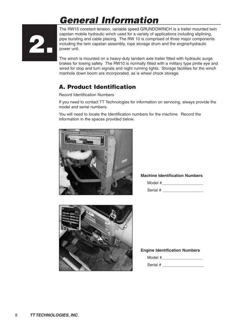
2.A. Product IdentificationRecord Identification Numbers
If you need to contact TT Technologies for information on servicing, always provide the model and serial numbers.
You will need to locate the Identification numbers for the machine. Record the information in the spaces provided below.
Machine Identification Numbers
Model #__________________
Serial # __________________
Engine Identification Numbers
Model #__________________
Serial # __________________

9TT TECHNOLOGIES, INC.
B. Control Identification
NUMBER DESCRIPTION 1 Battery 2 Engine oil 3 Air filter (when light is on filter needs service) 4 Low fuel (when light is on indicates low fuel) 5 Hour meter 6 Operation control indicator light (GREEN) 7A & 7B Control panel fuse & cooling fan fuse 8 System pressure/Tonnage gauge 9 Remote socket 10 Emergency - Stop 11 Tonnage selector 12 Speed/Range selector (5 ton/10 ton) 13 Line speed control 14 Rope pull out (green) 15 Stop (red) 16 Rope pull in (black) 17 12V Power socket 18 Starter button 19 Engine throttle lever 20 Ignition switch 21 Auxiliary hydraulic outlet selector (optional) 22 Auxiliary hydraulic coupler (optional) 23 Digital line counter (see appendix C for operation)
FIG. 1: GRUNDOWINCH CONTROLS
521 3 6 7 8
16 15 14 13171820
FIG. 1A: GRUNDOWINCH CONTROLS
9
11
12
19
4
10
2122
23
FIG. 1B: WINCH LINE REMOTE
10 TT TECHNOLOGIES, INC.
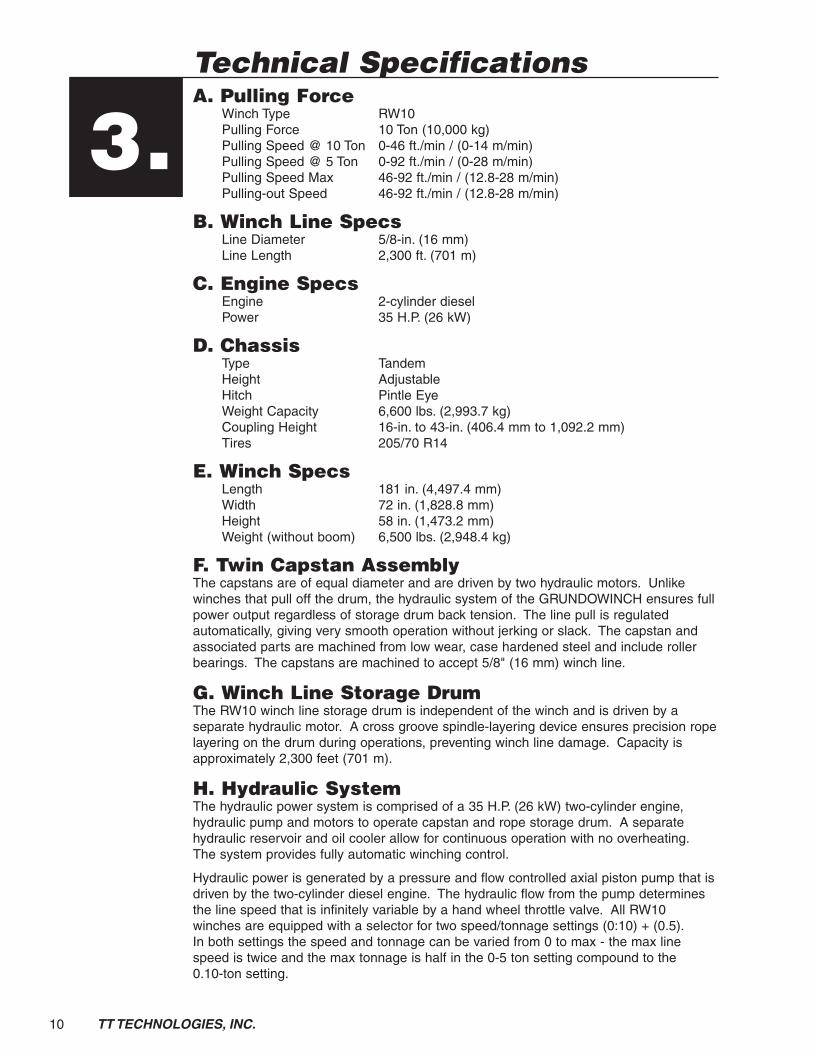
Technical SpecificationsA. Pulling Force Winch Type RW10 Pulling Force 10 Ton (10,000 kg) Pulling Speed @ 10 Ton 0-46 ft./min / (0-14 m/min) Pulling Speed @ 5 Ton 0-92 ft./min / (0-28 m/min) Pulling Speed Max 46-92 ft./min / (12.8-28 m/min) Pulling-out Speed 46-92 ft./min / (12.8-28 m/min)
B. Winch Line Specs Line Diameter 5/8-in. (16 mm) Line Length 2,300 ft. (701 m)
C. Engine Specs Engine 2-cylinder diesel Power 35 H.P. (26 kW)
D. Chassis Type Tandem Height Adjustable Hitch Pintle Eye Weight Capacity 6,600 lbs. (2,993.7 kg) Coupling Height 16-in. to 43-in. (406.4 mm to 1,092.2 mm) Tires 205/70 R14
E. Winch Specs Length 181 in. (4,497.4 mm) Width 72 in. (1,828.8 mm) Height 58 in. (1,473.2 mm) Weight (without boom) 6,500 lbs. (2,948.4 kg)
F. Twin Capstan AssemblyThe capstans are of equal diameter and are driven by two hydraulic motors. Unlike winches that pull off the drum, the hydraulic system of the GRUNDOWINCH ensures full power output regardless of storage drum back tension. The line pull is regulated automatically, giving very smooth operation without jerking or slack. The capstan and associated parts are machined from low wear, case hardened steel and include roller bearings. The capstans are machined to accept 5/8" (16 mm) winch line.
G. Winch Line Storage DrumThe RW10 winch line storage drum is independent of the winch and is driven by a separate hydraulic motor. A cross groove spindle-layering device ensures precision rope layering on the drum during operations, preventing winch line damage. Capacity is approximately 2,300 feet (701 m).
H. Hydraulic SystemThe hydraulic power system is comprised of a 35 H.P. (26 kW) two-cylinder engine, hydraulic pump and motors to operate capstan and rope storage drum. A separate hydraulic reservoir and oil cooler allow for continuous operation with no overheating. The system provides fully automatic winching control.
Hydraulic power is generated by a pressure and flow controlled axial piston pump that is driven by the two-cylinder diesel engine. The hydraulic flow from the pump determines the line speed that is infinitely variable by a hand wheel throttle valve. All RW10 winches are equipped with a selector for two speed/tonnage settings (0:10) + (0.5). In both settings the speed and tonnage can be varied from 0 to max - the max line speed is twice and the max tonnage is half in the 0-5 ton setting compound to the 0.10-ton setting.
3.

11TT TECHNOLOGIES, INC.
Safe Operating ProceduresA. Safety InstructionsFor your protection and the protection of others, practice the following safety rules. 1. Read operators manual and safety decals before operating this winch. 2. Only authorized personnel familiar with this winch and its functions to operate. 3. Do not use to lift, support or transport personnel. 4. ONLY pull load in horizontal direction. Do not use to lower or pull
equipment vertically. 5. Do not operatue until all safety shields are in place and controls
function properly. 6. Turn off engine and secure against accidental movement and/or unauthorized
start-up if leaving winch unattended. 7. Keep winch clear of motor vehicle traffic or provide barriers, signs and/or
warning lights. 8. Verify all safety shields are refitted after maintenance. 9. Provide a quality inspection by a qualified specialist at least once a year. 10. Shut off winch and wait for movement to stop before,
servicing, cleaning or inspecting. 11. Only authorized operations personnel to remain near
equipment while cable is pulled under load. 12. NEVER enter manhole or excavation pit while winch is
pulling cable under load. 13. Personal protective equipment is required while operating
this machine. Keep hands, feet and clothing away from power-driven parts.
B. Hydraulic Equipment 1. Tighten all connections before applying pressure.
Relieve pressure when service unit. 2. Check for leaks with a piece of cardboard. Do not use hands. 3. Do not exceed working pressure of hydraulic hoses. 4. Visually inspect hydraulic system and connections regularly. Service if needed
C. Rope Inspection, Maintenance (See Appendix A, B)
Transporting The GRUNDOWINCHA. Towing the Winch The RW10 has an adjustable hitch arm to allow the winch to be towed by vehicles with various height rear bumpers. By adjusting the two pivot points, the tandem tires will support the load at a level attitude at most vehicle hitch levels. 1. To change the winch attitude, lower the front jack stand to support the front of
the winch and provide a level winch attitude. Loosen the lock levels on each of the winch pivot points.
2. Raise or lower the hitch to the proper tow vehicle hitch height. 3. Tighten the lock levels and replace the safety pins prior to towing the winch. IMPORTANT: Winch must be level for safe highway towing. 4. Secure the military type locking pintle hitch on the tow vehicle to the RW10
pintle eye. The hitch must be securely mounted. Full range jack to prevent from hitting any obstacles.
4.
5.
Open operation panel to locate Safety Instructions.
12 TT TECHNOLOGIES, INC.
5. Check the mounting bolts regularly for tightness. 6. Connect the two high strength safety chains to the tow vehicle frame,
independent from the vehicle hitch. 7. Connect winch lights/electrical system to towing vehicle. Check that lights are
functioning correctly. 8. Connect emergency break-away brake actuator. 9. Check all accessories on winch that they are properly placed and secured. 10. After winch is properly secured to tow vehicle check that the manual brake is
released before towing.
CAUTION: The RW10 weighs in excess of 6,000 lbs (2,721.6 kg). The tow vehicle must be rated for this load.
A trailer connection light cable is provided to transfer lighting and signals to the winch. Check all lights for proper operation prior to towing. Due to the weight of the RW 10, limit operations to normal highway speeds and be aware of increased stopping distances with the winch attached. Rain, ice and snow will have a detrimental effect on safe highway operations.
B. Parking the WinchOn level ground simply apply the parking brake of the winch before uncoupling it from the towing vehicle.
In down-hill position apply the parking brake of the winch and put the chocks (held on the side of the winch) in front of both wheels.
In up-hill position allow the towing vehicle to roll back far enough to let the brake system engage into reverse mode, apply parking brake and put the chocks behind both wheels.
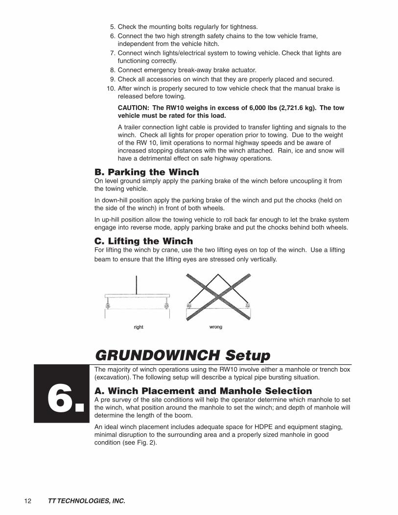
C. Lifting the WinchFor lifting the winch by crane, use the two lifting eyes on top of the winch. Use a lifting beam to ensure that the lifting eyes are stressed only vertically.
GRUNDOWINCH SetupThe majority of winch operations using the RW10 involve either a manhole or trench box (excavation). The following setup will describe a typical pipe bursting situation.
A. Winch Placement and Manhole SelectionA pre survey of the site conditions will help the operator determine which manhole to set the winch, what position around the manhole to set the winch; and depth of manhole will determine the length of the boom.
An ideal winch placement includes adequate space for HDPE and equipment staging, minimal disruption to the surrounding area and a properly sized manhole in good condition (see Fig. 2).
6.

13TT TECHNOLOGIES, INC.
In a pipe bursting application the receiving manhole or winch manhole selection is based on several factors including the following.
1. HDPE STAGING Adequate space is needed to safely and properly stage the fused length of HDPE prior to bursting. Avoiding public inconvenience or disruption such as blocked driveways or business entrances may require switching manhole choice.
2. OBSTACLES Any obstacles adjacent to the selected manhole such as street lights, trees, damaged walls, landscaping, etc. and ground conditions such as mud, water, decorative stone, peripheral utilities, etc. will affect where and how the winch can be set up.
3. MANHOLE CONSTRUCTION OR CONDITION Offset inverts and chimneys, damaged walls and loose bricks may make the manhole unusable.
4. FLOW DIRECTION Pipe bursting with the flow (if bypass pumping is a problem) is desirable, so the winch manhole selection may be indicated by flow direction.
5. MANHOLE AND EXPANDER SIZES Reversible GRUNDOCRACK tools utilize front or head expanders. Once the tool reaches the destination manhole, it is reversed out of the newly installed HDPE. The manhole diameter must be large enough to accept the front expander.
After the winch is in position over the manhole, pull the parking brake into the ON position. Place wheel chocks under tires on both sides of the winch and disconnect the tow vehicle.
NOTE: Cones, barricades, etc., should be placed around the winch in a traffic situation. A minimum 10-ft. (3 m) working radius around the winch is desired to prevent traffic problems.
GRUNDOWINCH®
Exit Pit
Entry Pit
GRUNDOWINCH®
Exit Pit
Entry Pit
Winch LineWinch Line Rear ExpanderRear Expander
GRUNDOCRACK®GRUNDOCRACK®
Old PipeOld Pipe
CompressorCompressor
New PE PipeNew PE Pipe
FIG. 2: MANHOLE SELECTION FOR GRUNDOWINCH PLACEMENT

14 TT TECHNOLOGIES, INC.
B. Boom AssemblyThe RW10 boom has a swivel assembly allowing the winch to be placed in any position around 360 degrees. This feature allows movement of the winch around the manhole due to structure, traffic or ground conditions. 1. Determine the distance from the winch/boom attachment point down to the
invert or pipe level in the manhole. Using a tape measure, measure from the invert or pipe bottom up to the mounting points.
2. Extend the main boom sections (upper and lower) to index a set of holes in each unit.
3. Secure the two boom sections together at the proper length using a fixing clamp. An extension may need to be added (3' or 6') (.9 m or 1.8 m) to read the proper length - refer to the following information for approximate lengths using supplied extensions.
Boom only- Closed - 5'2" or 62" (1,574.8 mm) Open - 7'2" or 86" (2,184.4 mm)
Boom with 3-ft. (.9 m) extension First hole - 8'2" or 98" (2,489.2 mm) Last hole - 10' 1 1/2"or 121 1/2" (3,086.1 mm)
Boom with 6-ft extension (1.8 m) First hole - 11' 1" or 133" (3,378.2 mm) Last hole - 13'1" or 156" (3,962.4 mm)
Boom with both 3-ft and 6-ft (.9 m and 1.8 m) extensions First hole - 14'1" or 169" (4,292.6 mm) Last hole - 16' 1/2" or 192 1/2" (4,889.5 mm)
NOTE: Winch output pulley/mounting points can be raised or lowered to “fine tune” the boom adjustment. Use the front jack and/or rear propping beams for minor adjustments. These adjustments are best left until the down boom is placed on the manhole.
C. Before Starting the Winch Check to see if it is safe around the winch before starting.
Check low fuel indicator light when ignition switch is on, if necessary fill with diesel fuel as required.
Check motor oil and hydraulic oil levels and fill as needed. (For type of oils to be used check Technical Specifications.)
Make sure all covers and shields are closed and secured, before start-up. (Except for winch controls cover.)
Caution: Do not run the winch in closed or poorly vented areas.
D. Starting Procedure Move the tonnage selector to the neutral position (0).
Turn line speed control hand wheel clockwise to its lowest output position. (Turtle)
Make sure either the remote control or blind plug is connected to the remote socket.
Set the engine throttle lever to a middle position. (Engine throttle level has an automatic shut down in the far right position.)
Turn the ignition swich to the on position.
FIG. 2A: TYPICAL 10-TON SWIVEL BOOM ASSEMBLY
Swivel Top Section
Intermediate Section
Sheave
Faceplate

15TT TECHNOLOGIES, INC.
Push in starter button to start engine. (Notice: do not press starter button for longer than 20 seconds. If winch did not start allow starter to cool before attempting to start again.)
Allow engine and hydraulic oil to warm before operating any functions.
Cold Starting Procedure In cold weather the engince and hydraulic oil need a longer warm up time, allow at
least 5-10 minutes at half throttle before operating any functions.
NOTICE: Never use any spray starting additives, damage to the engine could occur.
E. Winch Payout Procedure With engine running using the throttle lever increase engine speed to a 3/4 throttle.
Push the stop button on the winch or remote if attached. (Note: This is not the emergency stop button.)
Move tonnage selector to a middle position.
Turn line speed control handle counterclockwise to its highest output position. (Rabbit)
Pull winch line out as needed.
NOTICE: Move range selector to reach desirable payout.
F. Winch Line Installation After the boom is extended to the proper length, the winch rope must be pulled out
and inserted through the tops of the boom, down through the boom, with the eye exiting the lower winch pulley.
IMPORTANT: The two wire rope containment bolts and nuts must be removed to allow the winch rope eye to pass through and out the boom bottom prior tostarting the winch.
G. Boom Installation After the winch rope is installed in the assembled boom lower boom into the
manhole (see Fig. 3).
CAUTION: The assembled boom, especially with extensions installed, is too heavy for manual placement. The use of a backhoe to place the boom is recommended to avoid injury.
Boom faceplates need to be properly aligned with the host pipe and adequately supported and blocked to prevent damage to the boom and ensure trouble-free winching operations.
1. Secure lifting strap to the boom and backhoe, fitting the connecting ears of the boom swivel top into the studs at the output pulley and securing the holding pins.
2. Carefully lower the boom into place.
3. Check the lower faceplates of the boom for proper alignment with the pipe. Adjust if necessary.
GRUNDOWINCH®
Entry PitExit Pit
Entry Pit
Boom Loweredinto place
Old Pipe
CompressorCompressor
FIG. 3: GRUNDOWINCH BOOM PLACEMENT
CAUTION
Heavy Object.Lifting may cause personal injury.
Use lifting device when installing or removing for servicing.
16 TT TECHNOLOGIES, INC.
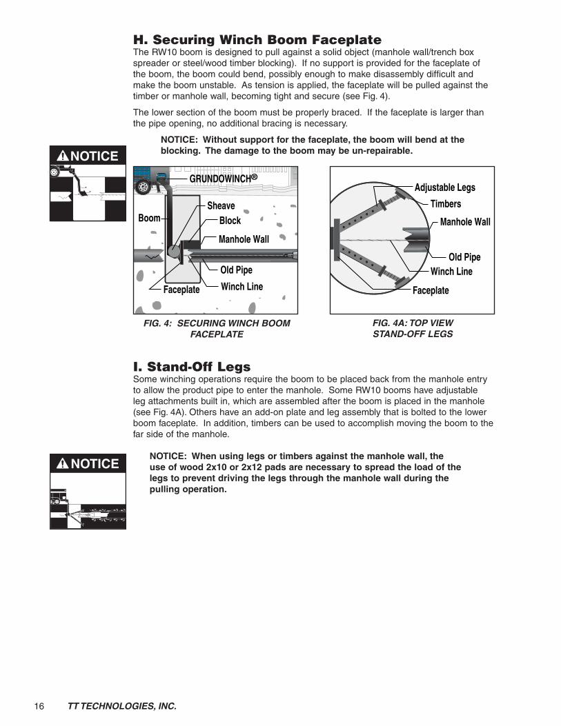
H. Securing Winch Boom FaceplateThe RW10 boom is designed to pull against a solid object (manhole wall/trench box spreader or steel/wood timber blocking). If no support is provided for the faceplate of the boom, the boom could bend, possibly enough to make disassembly difficult and make the boom unstable. As tension is applied, the faceplate will be pulled against the timber or manhole wall, becoming tight and secure (see Fig. 4).
The lower section of the boom must be properly braced. If the faceplate is larger than the pipe opening, no additional bracing is necessary.
NOTICE: Without support for the faceplate, the boom will bend at the blocking. The damage to the boom may be un-repairable.
I. Stand-Off LegsSome winching operations require the boom to be placed back from the manhole entry to allow the product pipe to enter the manhole. Some RW10 booms have adjustable leg attachments built in, which are assembled after the boom is placed in the manhole (see Fig. 4A). Others have an add-on plate and leg assembly that is bolted to the lower boom faceplate. In addition, timbers can be used to accomplish moving the boom to the far side of the manhole.
NOTICE: When using legs or timbers against the manhole wall, the use of wood 2x10 or 2x12 pads are necessary to spread the load of the legs to prevent driving the legs through the manhole wall during the pulling operation.
NOTICE
Entry Pit
GRUNDOWINCH®
BoomEntry Pit
Winch Line Rear ExpanderRear Expander
GRUNDOCRACK®GRUNDOCRACK®
Old Pipe
CompressorCompressor
New PE PipeNew PE Pipe
Faceplate
Block
Manhole Wall
Sheave
FIG. 4: SECURING WINCH BOOM FACEPLATE
Winch LineOld Pipe
Manhole Wall
Faceplate
Adjustable Legs
Timbers
FIG. 4A: TOP VIEW STAND-OFF LEGS
NOTICE

17TT TECHNOLOGIES, INC.
J. Stabilizing the WinchThe RW10 has two Front Stabilizers and two Rear Propping Legs in addition to the Front Jack Stand. This allows leveling both laterally and side to side. In most situations, this is done after the winch boom is in position.
1. Set the rear propping legs by pulling the fixing pins and dropping the legs.
2. Raise or lower the winch to level by pulling the faxing jack and re-installing the pins.
3. The rear propping legs are adjustable to provide proper clearance. Remove the first pin and slide the propping leg assemble out.
CAUTION: Never extend the leg past the last locating hole, as the entire leg assembly will fall from its socket.
4. Position the front legs in the same manner as the rear. Raise or lower the winch to index a locating hole.
NOTE: If the winch is positioned on uneven ground, use the propping bar to raise one side and level the winch.
K. Propping up the Winch (see Fig. 5, 6 & 7).1. Remove fixing pin (1) from horizontal propping beam (2).
2. Pull out horizontal propping beam (2) as far as required.
3. Re-insert fixing pin (1) when bores are in line and secure in place (3).
4. Remove the fixing pin (4) of prop (5), holding it to prevent it from falling.
5. Let prop (5) slip down to the ground.
6. Insert jacking-up wrench (6) with its front pin into the pivoting bore and its second pin into the upper prop bore.
7. Press wrench (6) down until fitting pin (4) fits into next upper bore.
8. Insert fixing pin (4) and remove jacking-up wrench (6).
9. Secure fixing pin (4) in place.
FIG. 5: REMOVE FIXING PIN
1
FIG. 6: PULL OUT PROPPING BEAM
4
36
2
1
5
4
5
FIG. 7: USE JACKING-UP WRENCH
4
625
18 TT TECHNOLOGIES, INC.
Operating Instructions— Pipe BurstingA. Winch Line Placement 1. Set winch in position over manhole as described in section 6A.
2. Secure winch brake, chock wheels, and set prop legs.
3. Install wire rope through boom as described in section 6C-E, extend boom to proper length and secure fixing clamps.
4. Install an Aramid fiber pull tape (with an elongation tensile of less than 5%) through the host pipe prior to the pipe burst. This step can be accomplished when the host pipe is jet cleaned or when the host pipe is video taped prior to the burst. The use of Jam skid corner sheaves may be required to prevent damage to the pull tape. The pull tape must be strong enough to pull the weight of the entire length of winch cable being pulled into the host pipe. The 5/8" cable, for the 10 ton GRUNDOWINCH, weighs 0.72 lbs. per foot and the 7/8" cable, for the 20 ton GRUNDOWINCH, weighs 1.42 lbs. per foot.
WARNING: Use of any alternate pull in method or pull in tape, to install the winch line, could result in death or serious injury and is not recommended by TT Technologies.
5. Attach pull tape to winch line.
6. The winch line can be pulled from the winch, through the boom, and into the host pipe. Continue pulling the tape until the winch line arrives at the entrance pit, make sure enough excess winch line is available to connect the winch line to the assembled pipe bursting unit.
WARNING: Pull tape only as fast as the winch cable payout will allow, pulling faster than cable payout could over stretch/tension the tape to the point of breaking. All personnel must remain clear while pulling tape to install winch cable. Failure to follow this warning could result in death or serious injury.
B. Winch OperationAfter the following preliminary steps are completed, the GRUNDOWINCH offers almost automatic operation. In most situations, no adjustments to the throttle or pull force will be necessary once bursting is underway. The RW10 automatically maintains tonnage and speed to keep up with the GRUNDOCRACK’s bursting speed.
IMPORTANT: Fluid levels should be checked and, if needed, replenished prior to starting a burst.
1. To start, shift the tonnage/pull selector to the desired range. The 0 to 5 t side is normally used for smaller diameter bursting operations 4", 6" (102, 152.4 mm) or short pulls. The 0 to 10t side is normally used for all other operations.
2. Set the tonnage selector to 0.
3. Push the pull-in button to set winch in retrieval mode.
4. Increase the throttle to fast (3/4 full).
5. Slowly move the tonnage selector up and watch as the rope starts to pull in. The force required to move the GRUNDOCRACK into position will depend onthe terrain conditions, length of fused HDPE, diameter and thickness of pipe. Continue to pull the GRUNDOCRACK into position, increasing the pull as needed.
7.
WARNING
WARNING

19TT TECHNOLOGIES, INC.
IMPORTANT: Good radio communications are a necessity as coordination between the winch, air compressor and entrance pit personnel is essential.
NOTE: In some cases, the GRUNDOCRACK unit can be helped along by a machine, (backhoe, trackhoe, dozer, etc.) to reduce the strain on the winch.
6. Pull the GRUNDOCRACK unit down the entrance pit and guide the nose of the hammer into the host pipe. Check the integrity of the boom bracing. Adjust if necessary.
7. The winch pull should be maintained at the tonnage required to “set” the GRUNDOCRACK in position, and the GRUNDOCRACK can be started.
NOTE: The GRUNDOCRACK’s bursting speed will be primarily determined by its ability to crack the pipe, expand the soil, and overcome the resistance of the new pipe as it is pulled through with the RW10 assisting all the above functions.
IMPORTANT: Increasing the pull of the winch will not, in all cases, increase the speed of the burst. Every burst is different and coordination of the winch and the GRUNDOCRACK provide the best burst speed.
8. Continue the bursting operation until the entire new pipe is installed and the GRUNDOCRACK reaches the winch manhole.
CAUTION: Do not leave winch unattended during bursting operations. The winch must be manned at all times to provide a safe operation.
IMPORTANT: The RW 10 should always continue to maintain pull until the GRUNDOCRACK is shut down to prevent the nose of the GRUNDOCRACK running over and damaging the winch cable.
C. Removal From The ManholeAs the GRUNDOCRACK approaches the exit manhole, communications with the compressor crew is vital to stop the airflow as the nose of the hammer enters the manhole. Damage to the downboom and manhole can occur if the GRUNDOCRACK is allowed to run too long.
1. As the cable eye enters the manhole, slowly lower the tonnage selector to 0 pull. Close the air compressor valve and open the air relief valve. This helps stop the GRUNDOCRACK.
NOTE: The expander of the reversible GRUNDOCRACK should enter the prepared manhole far enough to provide for the new product pipe in the manhole.
2. Remove the connection bolt/pin from the GRUNDOCRACK and disconnect the winch rope.
3. Remove the boom from the manhole.
4. Store the propping legs and wheel chocks. Release the parking brake and remove the winch from the manhole area.
CAUTION

20 TT TECHNOLOGIES, INC.
MaintenanceThe GRUNDOWINCH requires a minimum amount of maintenance. However, specific maintenance checks and inspections should be carried out on a regular basis in order to ensure trouble free operation. (Reference Hatz Engine Manual)
A. Maintenance Checks & Schedule1. Regularly lubricate all grease points according to the lubrication chart
(see Fig.8 & 8A).2. Check hydraulic fluid levels. Replenish if needed.3. Check hydraulic system including hoses and screw connections for leaks.4. Check engine oil level. Replenish if needed. 5. Check tire pressure. Inflate if needed.6. Check overrun braking system.
B. Recommended Oil & LubricantsHydraulic Oil Dexron III ATFEngine Oil 10W-40Gear Box Oil SAE 90Grease Multi-purpose
8.
FIG. 8: LUBRICATION AREA
FIG. 8A: LUBRICATION CHART

21TT TECHNOLOGIES, INC.
Troubleshooting Guide
Observation Reason Solution
1. Line pull indicator and preselector differ widely.
2. At stage 2 winch pulls normally but at stage 1 full line pull is not reached.
3. Winch stops at low line pull and line speed.
4. Winch stops although preselection lever is set to range 2.
5. Rope can not be pulled in or out.
No hydraulic pressure on the gauge.
Green control lamp on panel board is out.
Capstans do not revolve.
a) Bowden cable has become loose or out of adjustment.
a) 3-way ball valve defective: leakage between ball and housing; test by disconnect-ing pipe at ball cock; if ball lies loose in the housing, then ball cock is defective.
b) One of the capstan motors is defective: oil leakage due to mechanical failure; test by measuring leakage oil. Disconnect leakage line on upper then lower motor and close line to tank with plug;connect hose to leakage oil socket and hold it into a container. Start winch and pull rope in under load; leakage oil flow should not exceed 0.5 l/min.
a) Resistance in oil flow to capstan motors is too low.
a) Resistance in oil flow to capstan motors too low
a) “Emergency-stop” button has been pressed
b) Remote control socket is unplugged
c) Poor contact of electrical wires
d) Coupling has become loosen and is off the pummp shaft
e) Pivot pin of the pump will not be pushed by the bowden cable of the line-pull selection
f) Pump control unit defect
a) Turn setting screw of Bowden cable to exact position as per line pull indicator.
a) Replace ball valve.
b) Replace capstan motor.
a) At low line pull and line speed preselection lever should be in stage 1.
a) Readjust resistance valve; take off cap nut (wrench 22) and turn socket screw 1 or 2 turns into housing.
a) Engage “emergency-stop” button
b) Put remote control or dummy plug to the socket
c) Fit the cables of the solenoid valve directly to the battery
d) Refit the pump from the IC-engine, replace the coupling and secure it
e) Adjust bowden cable as per instruction
f) Replace pump
9.

22 TT TECHNOLOGIES, INC.
Observation Reason Solution
6. Rope does not pull out.
7. Rope pulls out very slow.
8. Rope drum overruns when rope is pulled out.
9. Winch does not pull (capstans turning).
10. Winch does not develop full line pull.
11. IC engine stalls.
12. Winch does not pull, oil pressure increases.
a) Controls are not properly set.
a) Engine speed is too low.
b) Line speed control not at maximum.
c) Line pull selection lever at stage 1 or set too low.
a) Brake pressure is too low.
a) Controls not properly set.
b) Rope drum blocked by foreign object.
c) Driving chain broke.
d) Oil motor has no advance.
e) Oil motor of rope drum defective.
a) Rope slips on capstans, oil pressure on rope drum motor is too low.
b) Pump defect.
a) Line speed setting is too high.
b) Hydraulic pump defective.
a) Rope twisted on capstans, capstans covering is worn out.
b) Oil motor of capstans is defective.
a) Set controls as per operating instructions.
a) Increase engine speed.
b) Set line speed control to maximum.
c) Set line pull selection lever to stage 2.
a) Increase brake pressure at brake pressure valve.
a) Set controls as per operating instructions.
b) Remove foreign object that may block or brake rope drum.
c) Replace chain.
d) Increase advance at the resistance valve.
e) Replace oil motor.
a) Increase pressure at pressure reduction valve - preselector.
b) Replace pump.
a) First set line speed to zero and increase slowly in proportion with pull line.
b) Replace pump.
a) Repair or replace capstan covering.
b) Repair or replace oil motor.

23TT TECHNOLOGIES, INC.
10.
11.DISCLAIMER FOR GRUNDOWINCH MANUAL:NO WARRANTY AS TO MANUALTT Technologies makes no warranty that the information provided in this manual is complete, accurate in all respects, or up to date. This manual should be used as a reference work to provide a starting point for addressing GRUNDOWINCH situations. Each particular situation is different. The user is responsible for providing the expertise and skill necessary to properly execute a given job. TT Technologies specifically disclaims all express or implied warranties concerning this manual, including the implied warranties of merchantability and fitness. In no event shall TT Technologies be liable for consequential, special or incidental damages or contingent liabilities (including, without limitation, lost profits or goodwill, whether such claim arises in tort, contract, negligence, strict liability or any other basis) arising in any way out of the use of this manual.
LIMITED WARRANTY AS TO PRODUCTSTT provides a limited warranty to the original purchaser of its new products that new products will be free from defects in materials and workmanship for 90 days or 500 hours of actual use, whichever occurs first, provided they are properly maintained serviced and used for the intended purpose of the product. During the 90 day or 500 hours period, buyer's remedies are limited to repair or replacement, at TT Technologies' discretion.
TT Technologies makes no other warranty, express or implied, and makes no warranty of merchantability or fitness for any particular purpose. No person, representative or agent of TT Technologies has the authority to change this warranty in any manner whatsoever. Any oral or written statements inconsistent with this limited warranty shall not apply.
In no event shall TT Technologies be liable for consequential, special or incidental damages or contingent liabilities (including, without limitation, lost profits or goodwill, whether such claim arises in tort, contract, negligence, strict liability or any other basis) arising in any way out of the use of any product or any parts thereof.
Replacement Parts ListDescription Part NumberEngine Oil Filter 40065300Engine Air Filter 00952900Fuel Filter H50251500Inline Pre-Fuel Filter 40089401Hydraulic Oil Filter 104.078.00
Warranty Information

24 TT TECHNOLOGIES, INC.
1. Mechanical damage due to rope movement over sharp edge projection while under load.
2. Localized wear due to abresaion on supporting structure.
3. Narrow path of wear resulting in fatigue fractures, caused by working in a grossly oversize groove, or over small support rollers.
4. Two parallel paths of broken wires indicative of bending through an undersize groove in the sheave.
5. Severe wear, associated with high tread pressure.
6. Severe wear in Langs Lay, caused by abrasion.
7. Severe corrosion.
8. Internal corrosion while external surface shows little evidence of deterioration.
9. Typical wire fractures as a result of bend fatigue.
10. Wire fractures at the strand, or core interface, as distinct from ‘crown’ fractures.
11. Break up of IWRC resulting from high stress application.
12. Looped wires as a result of torsional imbalance and/or shuck loading.
13. Typical example of localized wear and deformation.
14. Multi strand rope ‘bird caged’ due to torsional imbalance.
15. Protursion of rope center resulting from build up of turn.
16. Substantial wear and severe internal corrosion
12.
Appendix A. Typical Examples of Wire Rope Deterioration

25TT TECHNOLOGIES, INC.
FIG. 9: SPLIT THE ROPE FIG. 10: MAKE DESIRED LOOP
FIG. 11: ALTERNATE STRANDS FIG. 12: APPLY COMPRESSION FITTING
Appendix B. Rope/Winch Line HandlingA. Flemish Eye-Splice or "Molly Hogan"One of the simplest and quickest eye splices for both field use and in the shop is the Flemish Eye-Splice or "Molly Hogan" - sometimes referred to as the "Rolled In" eye splice. This is especially applicable to preformed wire rope.
1. Bind the rope from the end at a distance equal to the length of loop desired - plus an additional lenth of approximately ten times the rope diameter. Split the rope by separating three adjacent strands, leaving the other three strands and core intact (see Fig. 9).
2. Bend the sets of strands into the desired size loop, crossing over with one set in the same manner you would make a simple overhand knot. The two sets of strands will "lock" together (see Fig. 10).
3. Start laying the strand selections alternately back into the rope grooves, continuing until the sections are laid as deep into the throat as possible, allowing the six strands and core to project past the oval of the loop (see Fig. 11).
4. Cut the core, if it is a fiber core rope. At this point you may:
A) Apply a compression type fitting (see Fig. 12) or B) Hand tuck ends.

26 TT TECHNOLOGIES, INC.
B. Rope Handling1. Incorrect uncoiling/unreeling of wire rope will cause stresses in the lay of the rope
and may eventually affect its structure. Kinks may develop which will make rope handling more difficult (see Figs. 13 & 14).
2. Do not pull the rope over fixed objects or edges to prevent the strands from untwisting (see Fig. 15).
3. Always adjust rope pulleys in line with the pulling direction! Max deflection angle 4° (see Fig. 16).
4. Do not pull rope clamps over sharp angles or narrow bends to avoid tearing rope strands out of the pressing (see Figs.17 & 18).
FIG. 13: INCORRECT WAY FIG. 14: CORRECT WAY
FIG. 15: DO NOT PULL OVER FIXED OBJECTS
FIG. 16: ADJUST ROPE PULLEY
FIG. 17: INCORRECT WAY FIG. 18: CORRECT WAY
Sharp Angle
Flat Angle
27TT TECHNOLOGIES, INC.
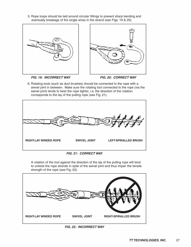
5. Rope loops should be laid around circular fittings to prevent sharp bending and eventually breakage of the single wires in the strand (see Figs. 19 & 20).
6. Rotating tools (such as duct brushes) should be connected to the rope with a swivel joint in between. Make sure the rotating tool connected to the rope (via the swivel joint) tends to twist the rope tighter, i.e. the direction of the rotation corresponds to the lay of the pulling rope (see Fig. 21).
A rotation of the tool against the direction of the lay of the pulling rope will tend to untwist the rope strands in spite of the swivel joint and thus impair the tensile strength of the rope (see Fig. 22).
FIG. 19: INCORRECT WAY FIG. 20: CORRECT WAY
FIG. 21: CORRECT WAY
FIG. 22: INCORRECT WAY
RIGHT-LAY WINDED ROPE SWIVEL JOINT LEFT-SPIRALLED BRUSH
RIGHT-LAY WINDED ROPE SWIVEL JOINT RIGHT-SPIRALLED BRUSH

28 TT TECHNOLOGIES, INC.
However, every rotating tool will tend to transmit a slight twist to the rope, even when the use of a good swivelling joint and a tool whose rotation corresponds to the lay of the rope strands. Hence, the rope may develop small loops which should be untwisted by hand before the rope is pulled in, but shrink into kinks which, when passed forcibly through narrow passages (guided pulley etc.), may damage the rope badly (see Fig. 23).
7. Always adjust pulleys in line with the direction of pull. Max. deflection angle 4° (see Figs. 24, 25 & 26). The diameter of external pulleys should not be smaller than that of the tail pulley of the winch.
FIG. 23: INCORRECT WAY
FIG. 24: ADJUST ROPE PULLEY FIG. 25: ADJUST ROPE PULLEY
FIG. 26: ADJUST ROPE PULLEY

29TT TECHNOLOGIES, INC.
Appendix C. Adjusting of the Electronic Meter Counter
1st Step Push the program button
2nd Step In the display appears: “COUNT HR TIMER”
Push the reset button until “COUNT” is in a flashing mode
Push the program button
3rd Step“COUNT” is in a flashing mode
Push the reset button three times. In the display appears “0003”
Push the program button
4th Step“COUNT” is in a flashing mode
In the Display appears “0003”
Push the program button four times
5th Step“COUNT” is in a flashing mode
In the display appears “0”
Push the program button
“COUNT” stops flashing. The gauge is set into feet counter modus.

30 TT TECHNOLOGIES, INC.
Appendix D. Using Battery Charger Battery gas is explosive:
DO NOT smoke while you charge battery.
Keep all flames and sparks away.
DO NOT charge frozen battery or low on electrolyte
DO NOT connect booster battery negative (—) cable to starting vehicle negative (—) terminal.
1. Access battery. (See procedure in Service section.)
2. Connect negative (—) booster cable to booster battery negative (—) post (C).
3. Connect the other end of negative (—) booster cable to engine ground (D), away from battery or starter.
4. Connect positive (+) booster cable to booster battery positive (+) post (B).
5. Connect the other end of positve (+) booster cable to:
Open station: Vehicle battery positive (+) post (A).
WARNING: Wear protective clothing and face shield when working around batteries. Batteries produce an explosive gas when being charged. Keep flames and sparks away from the battery area.
VEHICLE BATTERY BOOSTER BATTERY
TO ENGINEGROUND
A—Battery Positive (+) PostB—Engine GroundC—Booster Battery Negative (—) PostD—Booster Battery Positive (+) Post

31TT TECHNOLOGIES, INC.
Appendix E. Electric System Wiring Diagram Diesel Engine

32 TT TECHNOLOGIES, INC.
Appendix F. Electric System Wiring Diagram Switch Board

33TT TECHNOLOGIES, INC.
Appendix G. Hydraulic System Diagram

34 TT TECHNOLOGIES, INC.
Appendix H. Lighting System Diagram
35TT TECHNOLOGIES, INC.
Appendix I. Drawbar Operation Drawbar Type 102VB-2/ 162VB-2/ 252VB-2/ 352VB-2
Adjustment• Pull sping pin out
• Slacken the immobilizing handle (Fig. 27.A.1) tighten as far as the stop.
• Tear off the “adhesive strips” on the side pieces (by ripping upwards, press to the left and right) - height adjustment only on the handle (Fig. 27.D.1)
• The separator can now be adjusted 50° upwards and 10° downwards as far as the stops.
• Tighten the immobilizer handle again and secure by hitting with a hammer (rubber hammer).
• Insert the spring pin.
• Tighten the immobilizing handle again after approx. 80 miles.
Parallel adjustment (control rod) causes the overrun device to remain in the basic position - horizontal position - (Fig. 27.A)
Adjustment aid: The drawbar has an adjustment aid (Fig. 27.B). This enables easy, effortless adjustment of the coupling height. The integrated gas spring keeps the components - overrun device and adjustment piece approximately in balance.
Handbrake: The trailer is fitted with a handbrake lever (Fig. 27.C) for parking the trailer. The gas spring supports the braking force. The gas spring automatically tightens the wheel brake when the automatic reverse function (trailer rolls backwards) takes place.
Attention: Always pull the hand lever forcefully over dead center (see marked area)!
To release the handbrake reset the hand lever past the dead center into the zero position (Fig 27.C.1).
Hanging in the breakaway cable: Thread the breakaway cable through the lug welded on the side (breakaway cable guide) [Fig. 27.E.1] and loop the carbine in the lug provided (Fig 27.F). Care should be taken when do-ing this that the length of the breakaway cable is sufficient for taking corners. Otherwise the brake will be triggered. If there is no lug, loop the cable around the neck of the ball and click the carbine on the cable.
If the trailer is separated from the towing vehicle unintentionally the breakaway cable triggers the handbrake (emergency brake). The breakaway cable must be threaded into the breakaway cable guide so that the emergency brake functions properly.

36 TT TECHNOLOGIES, INC.
Appendix I. Drawbar Maintenance and CleaningEvery 16,000 to 24,000 miles or every 12 months:
Check the overrun device shock absorbers.
Inspection: 1. Slacken the transfer cable on one side (Fig 27.D.2).
2. A buffer force is encountered on pushing in.
Replace the dampers: If the force is very small
If there are air bags
If it is easy to pull out
When oil is leaking
Grease or oil the friction points or joints on the overrun device!
See Fig. 27.G for lubrication points.
Lubrication type: Multi-purpose grease as per DIN 51825 KTA 3K4.
If the adjustment drawbar remains at a certain coupling height over a longer period of time, so-called “fitting rust” can occur in the tooth lock washer connection. This leads to the tooth lock washers corroding tight. Clean the tooth lock washer conncetions regularly (every 6 months) and apply a water-repellent grease to prevent this happening. This also prevents “rust water” from running out.
Type of grease: Multi-purpose grease DIN 51502 KPF 2C
Lubricate all other joints and moving parts with oil.
Fault Finding Plan
Fault Cause Rectification
Braking effect too weak Drawbar pushes in all the way, friction loss too great, corro-sion on the drawbar
Check the brake adjustment, make the transfer device in-cluding the brake pull bar run easily and lubricate.
Reverse travel tight or blocked. Only occurs when the braking system is set too tight.
Reset the braking system
Hand brake effect too weak. Faulty gas spring Replace gas spring
Erratic performance or jerky braking
Faulty shock absorber Replace shock absorber
Trailer starts to brake when the throttle is taken off
Faulty shock absorber Replace shock absorber
Adjustment too tight Control rod joints tightAdjustment aid tight
Stacken, clean, lubricate and reset joints tightening moment (70Nm).

37TT TECHNOLOGIES, INC.
Appendix I.
Fig
. 27
DA B
H C
E F G

38 TT TECHNOLOGIES, INC.
Notes

39TT TECHNOLOGIES, INC.

Printed in USA • 01.01.06 • REV 1.5 Copyright© 2006, TT TECHNOLOGIES, Inc.
® TT Technologies,Inc.2020 E New York Street • Aurora, IL 60502 • 1-800-533-2078 • 1-630-851-8200 • FAX 1-630-851-8299
www.tttechnologies.com • E-mail [email protected] rights reserved. No part of this catalog may be reproduced or transmitted in any form or by any means, electronic or mechanical, including storage on an information retrieval system, without written permission from TT TECHNOLOGIES, Inc.