intellisystem technologies - :// · pdf fileit210 user’s manual intellisystem...
TRANSCRIPT

Intellisystem Technologies - http://www.intellisystem.it
IT210 User’s Manual
Intellisystem Technologies - http://www.intellisystem.it
1
Table of Contents
Table of Contents....................................................................................1
Before You Use........................................................................................5
Package Contents ...................................................................................6
Physical Description...............................................................................7
Rear Panel............................................................................................................7 Ethernet 10/100 socket ................................................................................................................. 7 COM port...................................................................................................................................... 7 General I/O terminal block ........................................................................................................... 8 Status LEDs .................................................................................................................................. 9 Restore button............................................................................................................................. 10 Power adapter ............................................................................................................................. 10 Auto Iris Lens Connector ........................................................................................................... 10
How to Install .......................................................................................11
Ethernet Environment .........................................................................12
Hardware installation.......................................................................................12 Cable connection ........................................................................................................................ 12 Power on ..................................................................................................................................... 13
Software configuration .....................................................................................14 Easy way with installer program ................................................................................................ 14 Manual way with existing programs........................................................................................... 19
First access to the IT210 Network Camera ....................................................20
Modem Environment ...........................................................................22
IT210 User’s Manual
Intellisystem Technologies - http://www.intellisystem.it
2
Hardware installation.......................................................................................22 Cable connection ........................................................................................................................ 23 Power on ..................................................................................................................................... 23
Software configuration .....................................................................................24 Install a new modem................................................................................................................... 24 Setup a new connection .............................................................................................................. 27
First access to the IT210 Network Camera ....................................................33 Authentication ...................................................................................................35 Primary user’s capability .................................................................................37
Main screen with camera view ................................................................................................... 37 Video quality selection ............................................................................................................... 40 Video size selection .................................................................................................................... 41 Pan/Tilt positioning device control............................................................................................. 42
System configuration ........................................................................................43 System parameters ...................................................................................................................... 44 User group administration .......................................................................................................... 45 Network settings ......................................................................................................................... 46 Video parameters ........................................................................................................................ 50 Camera positioning device configuration................................................................................... 52 Modem and dial-up settings........................................................................................................ 55 Application ................................................................................................................................. 57 Demonstration account settings.................................................................................................. 61 Homepage layout settings........................................................................................................... 62 One-shot fast configuration via FTP........................................................................................... 63
Advanced functions...........................................................................................72 Alarm settings............................................................................................................................. 72 Viewing system log .................................................................................................................... 73 Viewing system parameters ........................................................................................................ 73 Restore factory default settings .................................................................................................. 73 Clear data path for proprietary commands ................................................................................. 73 Uploading snapshots periodically to an external FTP server...................................................... 74 Viewing and downloading the stored snapshots ......................................................................... 74
IT210 User’s Manual
Intellisystem Technologies - http://www.intellisystem.it
3
Downloading the update snapshots ............................................................................................ 74 Customizing images of homepage.............................................................................................. 75 Viewing system log .................................................................................................................... 75 Uploading the configuration file................................................................................................. 75 Software revision upgrade .......................................................................................................... 76 System core debugging............................................................................................................... 77 Monitor changed status of digital inputs .................................................................................... 77 Stop information dumping.......................................................................................................... 77 Query status of digital inputs...................................................................................................... 78 Set digital outputs ....................................................................................................................... 78 Erase snapshots stored in Flash memory .................................................................................... 78 Erase logo and graphic buttons................................................................................................... 78 Skip installation at next boot ...................................................................................................... 78 Reset network for new settings................................................................................................... 78 Restore factory default settings .................................................................................................. 78 Reset system ............................................................................................................................... 78
URL commands of the IT210 Network Camera ............................................79 Capture update Snapshot of video channel................................................................................. 79 Display images ........................................................................................................................... 79 Get stored snapshots from Flash memory .................................................................................. 81 Move positioning device in PT direction.................................................................................... 81 Query status of digital inputs...................................................................................................... 81 Drive digital outputs ................................................................................................................... 81 Clear data mode serial port driver .............................................................................................. 81 Restore factory default settings .................................................................................................. 82 Restart system............................................................................................................................. 82 Page URL ................................................................................................................................... 83 System resource URL................................................................................................................. 84 General format of command URL.............................................................................................. 84 System configuration URL ......................................................................................................... 84 Users configuration URL............................................................................................................ 85 Network configuration URL....................................................................................................... 85
IT210 User’s Manual
Intellisystem Technologies - http://www.intellisystem.it
4
Video configuration URL ........................................................................................................... 86 Image quality configuration URL............................................................................................... 88 Camera control configuration URL ............................................................................................ 88 Camera custom command configuration URL ........................................................................... 89 Modem configuration URL ........................................................................................................ 89 Application configuration URL.................................................................................................. 90 Motion detection configuration URL ......................................................................................... 90 Demo configuration URL........................................................................................................... 91 Homepage layout configuration URL ........................................................................................ 91
Appendix ...............................................................................................92
A. POST procedure...........................................................................................92 B. Frequently asked questions .........................................................................93 C. Technical specifications ...............................................................................96
IT210 User’s Manual
Intellisystem Technologies - http://www.intellisystem.it
5
Before You Use Surveillance devices may be prohibited by law in your country. Though the IT210 Network Camera
is not only a high performance surveillance system but also a networked video server, ensure that the operation of such devices are legal before installing this unit for surveillance.
It is important to carefully check the contents with the "Package Contents" section after opening the
package. Understanding the physical description can prevent damage caused by abnormal usage and reduce most problems during installation.
Basically the IT210 Network Camera is a network device and should be easy to use for those who
already have basic network knowledge. If there is a system error and it does not recover easily due to erroneous configuration, check the section "Auxiliary buttons" to restore factory default settings
and run installation again.
The IT210 Network Camera has been designed for various environments and can be used to build various applications for general security or demonstration purposes. For standard applications, read
"System configuration" to understand all functions. To make best use of the IT210 Network Camera,
review "Advanced functions" to get creative ideas. To those professional developers, "URL
Commands of the IT210 Network Camera" will be a very helpful reference.
Those paragraphs preceding by should be fully understood and cautioned. Ignoring the
warnings may result in serious hazards.
IT210 User’s Manual
Intellisystem Technologies - http://www.intellisystem.it
6
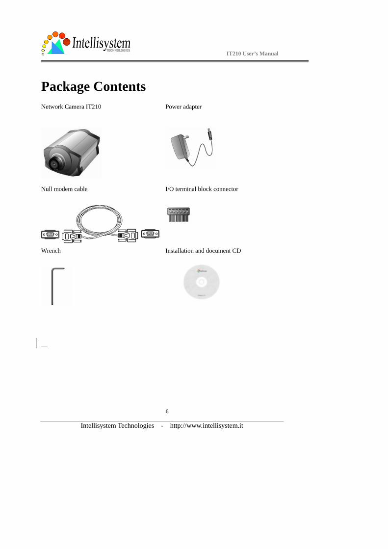
Package Contents Network Camera IT210
Power adapter
Null modem cable
I/O terminal block connector
Wrench
Installation and document CD

IT210 User’s Manual
Intellisystem Technologies - http://www.intellisystem.it
7
Physical Description
Rear Panel
Ethernet 10/100 socket Connect to Ethernet network with a UTP category 5 cable that cannot exceed 100 meters. Once the
Ethernet cable is connected without error, the IT210 Network Camera will utilize Ethernet interface
regardless of modem connection.
COM port This RS232 serial port can connect with a modem or included null modem cable to utilize dial-up
network when Ethernet is not available. If the IT210 Network Camera operates with Ethernet interface, administrators may use this port to control the attached PT positioning device.
IT210 User’s Manual
Intellisystem Technologies - http://www.intellisystem.it
8
General I/O terminal block
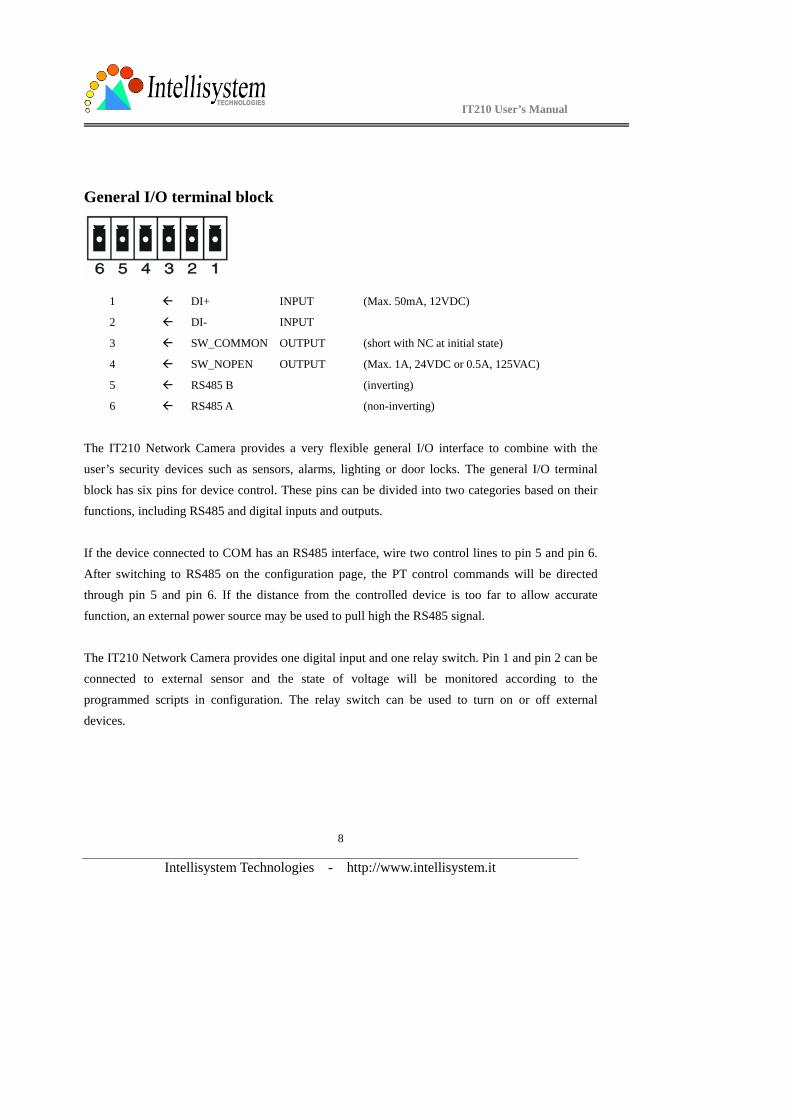
1 DI+ INPUT (Max. 50mA, 12VDC)
2 DI- INPUT
3 SW_COMMON OUTPUT (short with NC at initial state)
4 SW_NOPEN OUTPUT (Max. 1A, 24VDC or 0.5A, 125VAC)
5 RS485 B (inverting)
6 RS485 A (non-inverting)
The IT210 Network Camera provides a very flexible general I/O interface to combine with the
user’s security devices such as sensors, alarms, lighting or door locks. The general I/O terminal
block has six pins for device control. These pins can be divided into two categories based on their functions, including RS485 and digital inputs and outputs.
If the device connected to COM has an RS485 interface, wire two control lines to pin 5 and pin 6.
After switching to RS485 on the configuration page, the PT control commands will be directed through pin 5 and pin 6. If the distance from the controlled device is too far to allow accurate
function, an external power source may be used to pull high the RS485 signal.
The IT210 Network Camera provides one digital input and one relay switch. Pin 1 and pin 2 can be connected to external sensor and the state of voltage will be monitored according to the
programmed scripts in configuration. The relay switch can be used to turn on or off external
devices.
IT210 User’s Manual
Intellisystem Technologies - http://www.intellisystem.it
9
Status LEDs
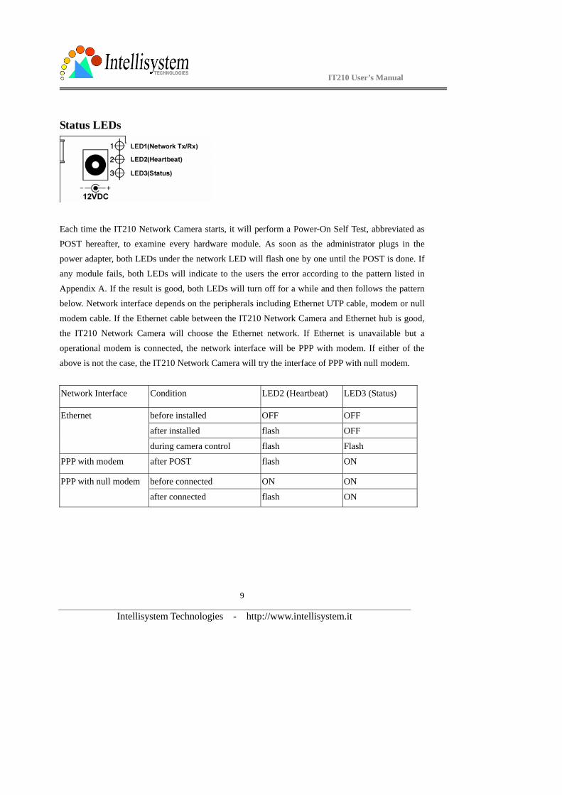
Each time the IT210 Network Camera starts, it will perform a Power-On Self Test, abbreviated as POST hereafter, to examine every hardware module. As soon as the administrator plugs in the
power adapter, both LEDs under the network LED will flash one by one until the POST is done. If
any module fails, both LEDs will indicate to the users the error according to the pattern listed in
Appendix A. If the result is good, both LEDs will turn off for a while and then follows the pattern below. Network interface depends on the peripherals including Ethernet UTP cable, modem or null
modem cable. If the Ethernet cable between the IT210 Network Camera and Ethernet hub is good,
the IT210 Network Camera will choose the Ethernet network. If Ethernet is unavailable but a
operational modem is connected, the network interface will be PPP with modem. If either of the above is not the case, the IT210 Network Camera will try the interface of PPP with null modem.
Network Interface Condition LED2 (Heartbeat) LED3 (Status)
before installed OFF OFF
after installed flash OFF
Ethernet
during camera control flash Flash
PPP with modem after POST flash ON
before connected ON ON PPP with null modem
after connected flash ON
IT210 User’s Manual
Intellisystem Technologies - http://www.intellisystem.it
10
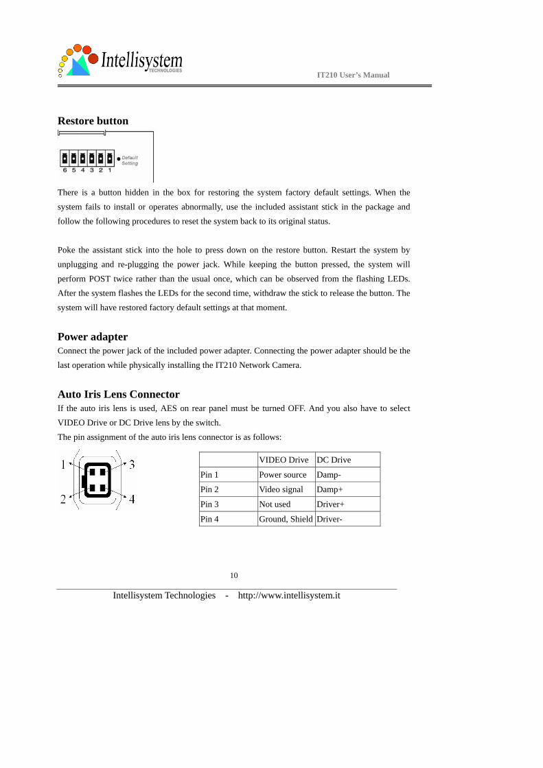
Restore button
There is a button hidden in the box for restoring the system factory default settings. When the
system fails to install or operates abnormally, use the included assistant stick in the package and
follow the following procedures to reset the system back to its original status.
Poke the assistant stick into the hole to press down on the restore button. Restart the system by
unplugging and re-plugging the power jack. While keeping the button pressed, the system will
perform POST twice rather than the usual once, which can be observed from the flashing LEDs. After the system flashes the LEDs for the second time, withdraw the stick to release the button. The
system will have restored factory default settings at that moment.
Power adapter Connect the power jack of the included power adapter. Connecting the power adapter should be the
last operation while physically installing the IT210 Network Camera.
Auto Iris Lens Connector If the auto iris lens is used, AES on rear panel must be turned OFF. And you also have to select
VIDEO Drive or DC Drive lens by the switch.
The pin assignment of the auto iris lens connector is as follows:
VIDEO Drive DC Drive
Pin 1 Power source Damp-
Pin 2 Video signal Damp+
Pin 3 Not used Driver+
Pin 4 Ground, Shield Driver-
IT210 User’s Manual
Intellisystem Technologies - http://www.intellisystem.it
11
How to Install To easily fit into various environments, the IT210 Network Camera automatically detects the
attached interfaces and configures itself to the best condition. Therefore users need not care how to select the network between Ethernet and modem, and whether the Ethernet speed is 10Mbps or 100
Mbps. The high performance built-in CCD and lens always give users delicate image quality.
The IT210 Network Camera supports Ethernet and modem interfaces according to the user's existing network. Ethernet can provide higher bandwidth to achieve the best performance while
dial-up network with modem is more common in current Internet applications. Refer to the related
installation section for your network environment. If both interfaces are available, Ethernet is
recommended and will be chosen as the first priority if Ethernet cable and modem are concurrently attached. Managing to install in the other interface will automatically clear the previous network
settings to start new installation.
In the following content, "user" refers to those who can access the IT210 Network Camera and "administrator" means the supervisor who has the root password to configure the IT210 Network
Camera in addition to general access. Administrators should carefully read this manual, especially
during installation.

IT210 User’s Manual
Intellisystem Technologies - http://www.intellisystem.it
12
Ethernet Environment
Hardware installation
Before installing multiple IT210 Network Cameras at the well-chosen locations, the administrator
should memorize the serial numbers on the packages respectively for future use.
Cable connection
Shut down all the peripheral devices prior to connection. Connect the supplied cables from the
IT210 Network Camera to related devices according to the above diagram. Note that the power
adaptor must be kept unplugged until other cables are firmly connected.
IT210 User’s Manual
Intellisystem Technologies - http://www.intellisystem.it
13
Power on Make sure all cables are correctly and firmly connected before turning on the IT210 Network
Camera. Turn on cameras, sensors, alarm devices, and then attach the power adaptor of the IT210
Network Camera to the electric power socket*. After the POST (power-on self test) is complete and the result is successful, the IT210 Network Camera is ready for software configuration as described
in this manual. At this stage, network speed and video modulation type are automatically detected.
If the detection of video modulation fails, administrators may change the setting on the
configuration page. Refer to the configuration section for further information.
Connect the power jack of the power adapter to the IT210 Network Camera prior to plugging
the utility end into the utility power socket. It will reduce accidental electric surge shock.
IT210 User’s Manual
Intellisystem Technologies - http://www.intellisystem.it
14
Software configuration
Easy way with installer program In order to configure IT210 Network Camera remotely, administrators should keep the serial numbers of the new IT210 Network Camera for identification and initial passwords. After
successfully mounting IT210 Network Camera in the proper position, run the Installer program on
the appropriate PC to locate the newly installed IT210 Network Camera. IT210 Network Camera
also support manual setup procedures to non-Windows based environments. The manual procedure is described next.
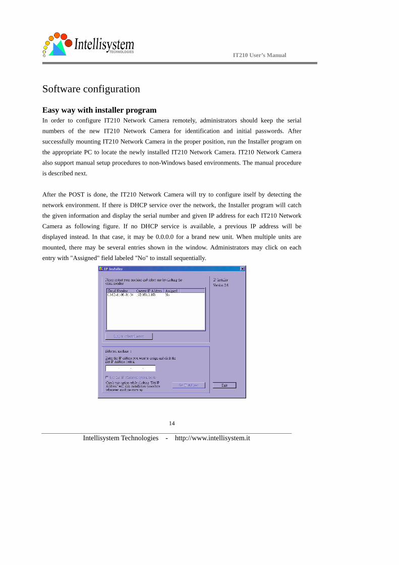
After the POST is done, the IT210 Network Camera will try to configure itself by detecting the
network environment. If there is DHCP service over the network, the Installer program will catch the given information and display the serial number and given IP address for each IT210 Network
Camera as following figure. If no DHCP service is available, a previous IP address will be
displayed instead. In that case, it may be 0.0.0.0 for a brand new unit. When multiple units are
mounted, there may be several entries shown in the window. Administrators may click on each entry with "Assigned" field labeled "No" to install sequentially.
IT210 User’s Manual
Intellisystem Technologies - http://www.intellisystem.it
15
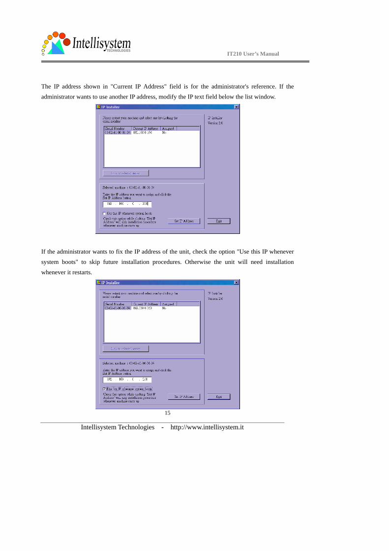
The IP address shown in "Current IP Address" field is for the administrator's reference. If the
administrator wants to use another IP address, modify the IP text field below the list window.
If the administrator wants to fix the IP address of the unit, check the option "Use this IP whenever
system boots" to skip future installation procedures. Otherwise the unit will need installation
whenever it restarts.
IT210 User’s Manual
Intellisystem Technologies - http://www.intellisystem.it
16
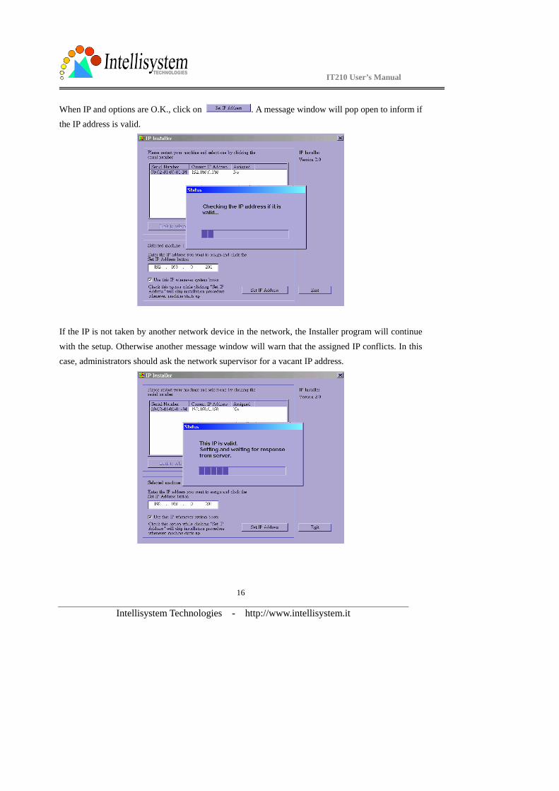
When IP and options are O.K., click on . A message window will pop open to inform if the IP address is valid.
If the IP is not taken by another network device in the network, the Installer program will continue
with the setup. Otherwise another message window will warn that the assigned IP conflicts. In this case, administrators should ask the network supervisor for a vacant IP address.
IT210 User’s Manual
Intellisystem Technologies - http://www.intellisystem.it
17
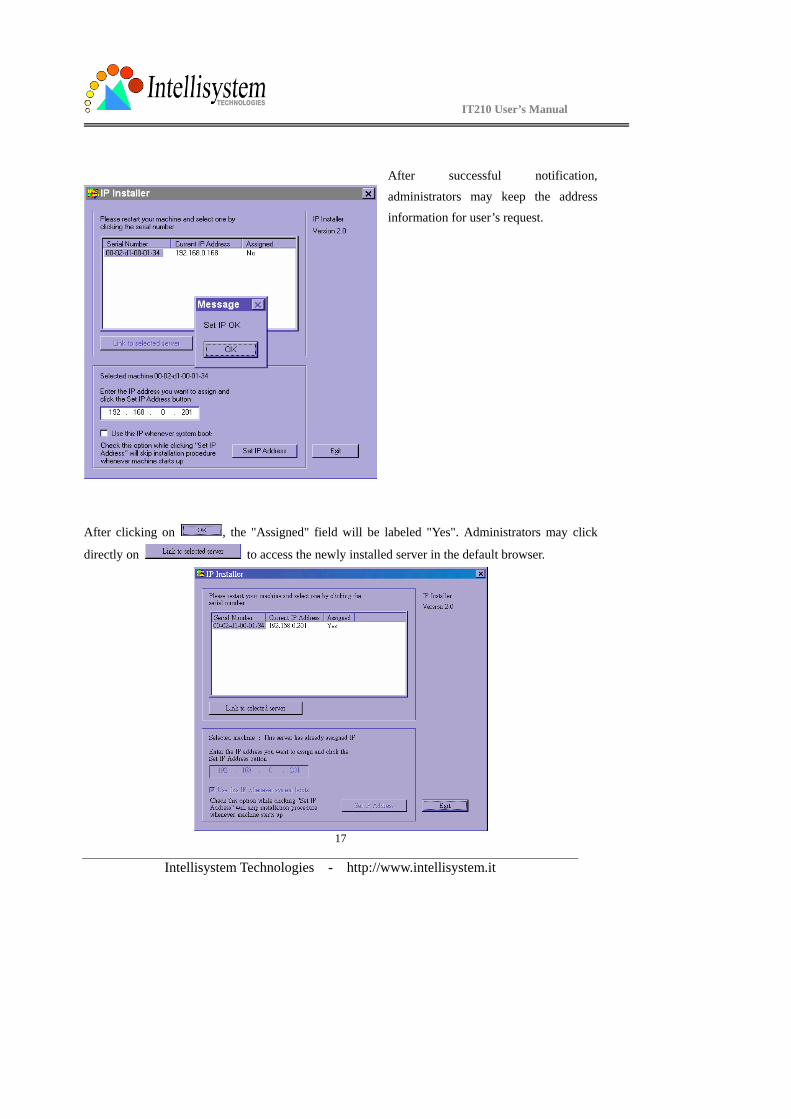
After successful notification,
administrators may keep the address
information for user’s request.
After clicking on , the "Assigned" field will be labeled "Yes". Administrators may click
directly on to access the newly installed server in the default browser.
IT210 User’s Manual
Intellisystem Technologies - http://www.intellisystem.it
18
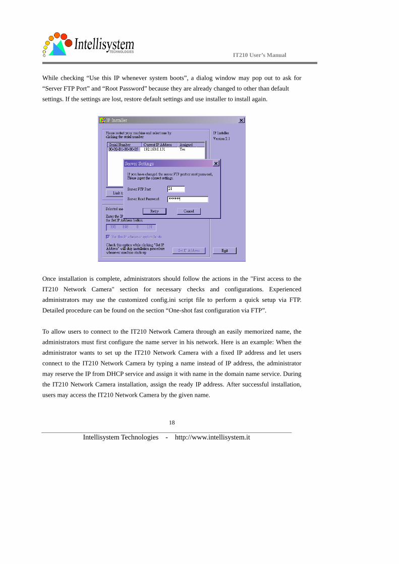
While checking “Use this IP whenever system boots”, a dialog window may pop out to ask for “Server FTP Port” and “Root Password” because they are already changed to other than default
settings. If the settings are lost, restore default settings and use installer to install again.
Once installation is complete, administrators should follow the actions in the "First access to the
IT210 Network Camera" section for necessary checks and configurations. Experienced administrators may use the customized config.ini script file to perform a quick setup via FTP.
Detailed procedure can be found on the section “One-shot fast configuration via FTP”.
To allow users to connect to the IT210 Network Camera through an easily memorized name, the administrators must first configure the name server in his network. Here is an example: When the
administrator wants to set up the IT210 Network Camera with a fixed IP address and let users
connect to the IT210 Network Camera by typing a name instead of IP address, the administrator
may reserve the IP from DHCP service and assign it with name in the domain name service. During the IT210 Network Camera installation, assign the ready IP address. After successful installation,
users may access the IT210 Network Camera by the given name.
IT210 User’s Manual
Intellisystem Technologies - http://www.intellisystem.it
19
Manual way with existing programs For those environments such as MAC, Linux, Unix or other operating systems, whose installer is
not yet available, some common network tools including ARP and PING can be used to install the IT210 Network Camera. Make sure ARP and PING programs exist in your operating system.
First, type arp –s “assigned IP address” “Ethernet address” to add an entity in the system’s name
table. The Ethernet address is identical to the serial number of the IT210 Network Camera and should be typed in the appropriate format like “uu-vv-ww-xx-yy-zz” or “uu:vv:ww:xx:yy:zz”,
which depends on the operating system.
Once a name entity is added, type ping "assigned IP address” to invite the new IT210 Network Camera. If it replies, that means the IT210 Network Camera has accepted the assigned IP address
and is ready for access. The first several ping requests may fail during the self-configuration period
of the IT210 Network Camera. Since the accurate grammar of ARP and PING depends on the
operating system, refer to its related help manual.
IT210 User’s Manual
Intellisystem Technologies - http://www.intellisystem.it
20
First access to the IT210 Network Camera
When connecting to the IT210 Network Camera for the first time, administrators should check
users and network settings on the configuration page. For complete protection from illegal usage, the IT210 Network Camera provides three privileges and always needs user name and password
before access. The lowest level is DEMO mode whose services are subject to administrator's
permission. The standard level is the USER mode that consists of twenty user profiles. Each user is
able to access the IT210 Network Camera, except for system configuration. The twenty user profiles are also maintained by the administrator. The highest level is ROOT mode that only opens
to administrators for initial setup, system configuration, users administration and software upgrade.
The user name of the administrator is internally assigned to “root”.
When connecting to the IT210 Network Camera, users will be requested for user name and
password by an authentication message window. A root password, identical to the IT210 Network
Camera's serial number, is needed for the initial access to a newly installed IT210 Network Camera.
The administrator must change the root password immediately after the initial installation to ensure security. The new root password should be well memorized since there is no way to retrieve or
recover it. After changing the password, the browser will display an authentication window again to
ask for the new password.
The other important part is network settings. The software configuration above makes the IT210
Network Camera easily accessed through local networks. However administrators should review
the network settings on the configuration page according to the existing service. The safe and easy
way is to compare the network settings with another PC or workstation in the same network.
The software installation in the previous section only set the host IP address and default subnet
mask as 255.255.255.0. Administrators should change the subnet mask if it differs from the one
provided by the server. Administrators should also fill in the default gateway, primary and secondary domain name servers if necessary.
By default the IT210 Network Camera will need administrator's installation every time it reboots. If

IT210 User’s Manual
Intellisystem Technologies - http://www.intellisystem.it
21
the network settings are sure to work all the time, disable the install option if this IP address is already reserved for this IT210 Network Camera. Clearing this option will skip the installation
procedure during the next power-up and use the previous settings. If the install option stays
checked,
the IT210 Network Camera will perform the installation procedure every time the system boots up.
Details about configurations are described in the "How to Use" section. Related figures are attached
for easy reference.
IT210 User’s Manual
Intellisystem Technologies - http://www.intellisystem.it
22
Modem Environment
Hardware installation
Before installing the IT210 Network Camera, the administrator should memorize the serial numbers
on the packages respectively for the initial passwords.
To use a dial-up network, the Ethernet socket should be left disconnected since Ethernet is the first
priority among available interfaces. After powering up, the IT210 Network Camera will detect if
any external modem is connected to the modem port. Once a modem is detected, the heartbeat LED
will flash periodically. If no modem responds, the IT210 Network Camera will assume the included null modem cable is connected to perform system configuration. Then both LEDs under the power
LED will turn on until null modem connection is established.
If users have setup a remote dialup server or subscribed to an ISP service, the IT210 Network Camera can be configured to dial to the server upon special events. Otherwise it will wait
permanently for the user’s call to establish a network connection to provide services.
In the following content, dial-in connection denotes a passive IT210 Network Camera waiting for a phone call to establish a point-to-point connection. Dial-out connection denotes an active IT210
Network Camera to dial out to the other end of a dial-up server or any Internet service provider,
abbreviated as ISP, to request a point-to-point connection.
IT210 User’s Manual
Intellisystem Technologies - http://www.intellisystem.it
23
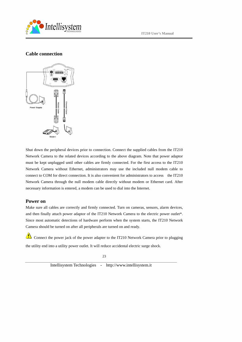
Cable connection
Shut down the peripheral devices prior to connection. Connect the supplied cables from the IT210 Network Camera to the related devices according to the above diagram. Note that power adaptor
must be kept unplugged until other cables are firmly connected. For the first access to the IT210
Network Camera without Ethernet, administrators may use the included null modem cable to
connect to COM for direct connection. It is also convenient for administrators to access the IT210 Network Camera through the null modem cable directly without modem or Ethernet card. After
necessary information is entered, a modem can be used to dial into the Internet.
Power on Make sure all cables are correctly and firmly connected. Turn on cameras, sensors, alarm devices,
and then finally attach power adaptor of the IT210 Network Camera to the electric power outlet*.
Since most automatic detections of hardware perform when the system starts, the IT210 Network
Camera should be turned on after all peripherals are turned on and ready.
Connect the power jack of the power adapter to the IT210 Network Camera prior to plugging
the utility end into a utility power outlet. It will reduce accidental electric surge shock.
IT210 User’s Manual
Intellisystem Technologies - http://www.intellisystem.it
24
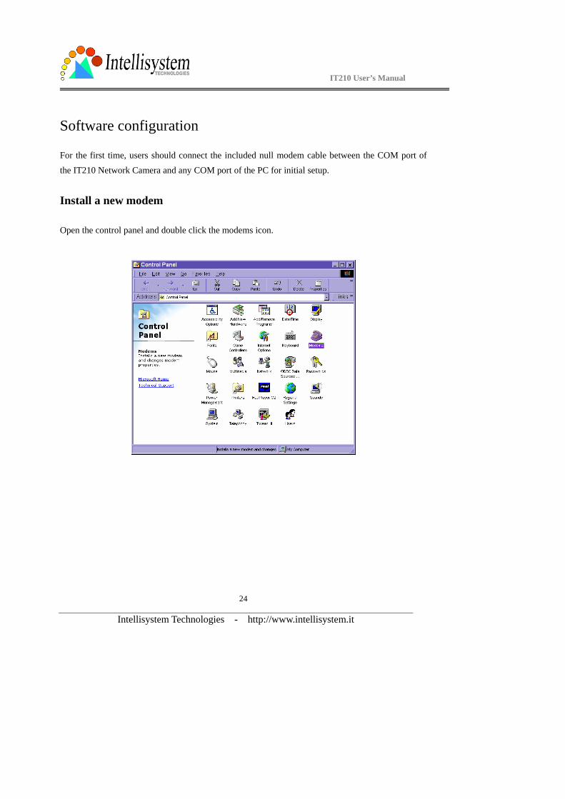
Software configuration
For the first time, users should connect the included null modem cable between the COM port of
the IT210 Network Camera and any COM port of the PC for initial setup.
Install a new modem
Open the control panel and double click the modems icon.
IT210 User’s Manual
Intellisystem Technologies - http://www.intellisystem.it
25
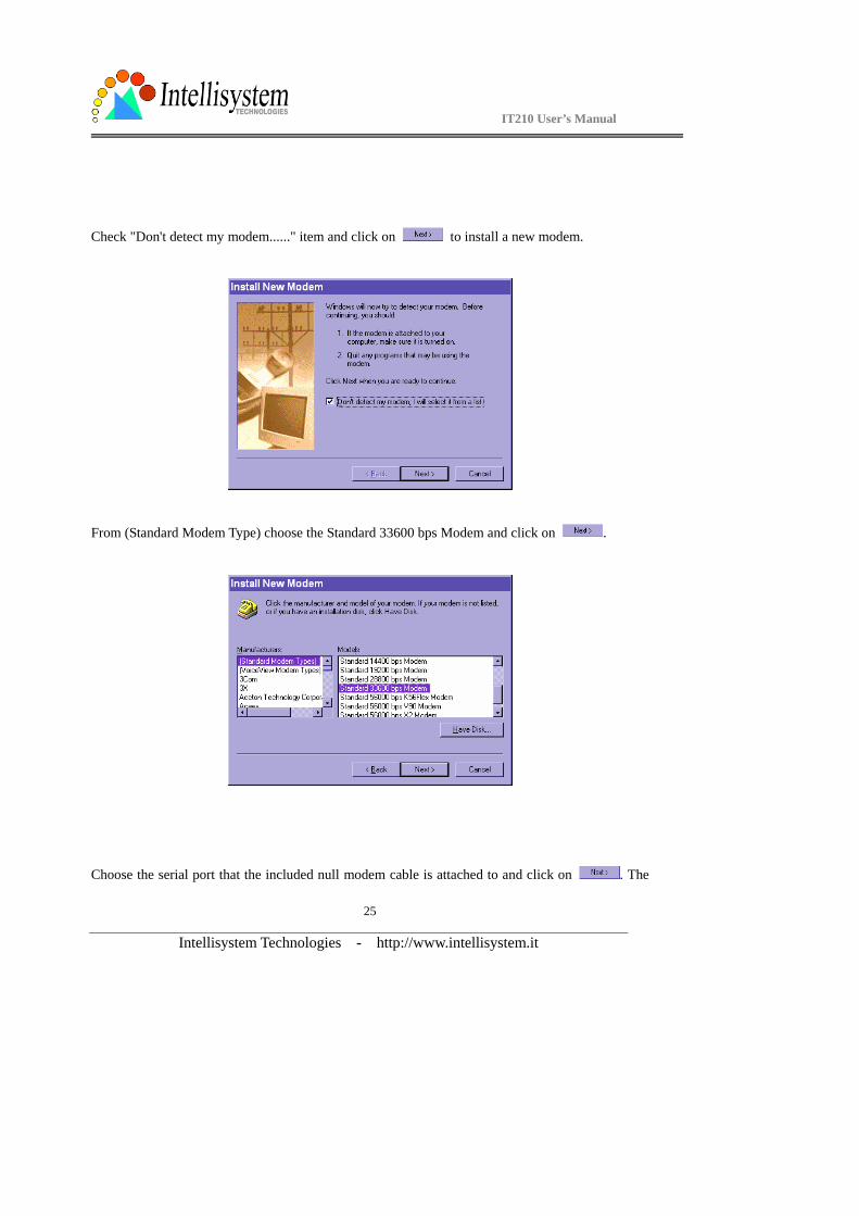
Check "Don't detect my modem......" item and click on to install a new modem.
From (Standard Modem Type) choose the Standard 33600 bps Modem and click on .
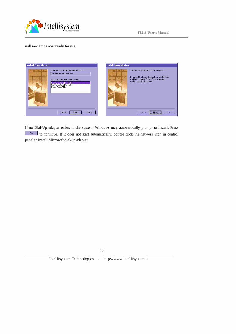
Choose the serial port that the included null modem cable is attached to and click on . The
IT210 User’s Manual
Intellisystem Technologies - http://www.intellisystem.it
26
null modem is now ready for use.
If no Dial-Up adapter exists in the system, Windows may automatically prompt to install. Press
to continue. If it does not start automatically, double click the network icon in control panel to install Microsoft dial-up adapter.
IT210 User’s Manual
Intellisystem Technologies - http://www.intellisystem.it
27
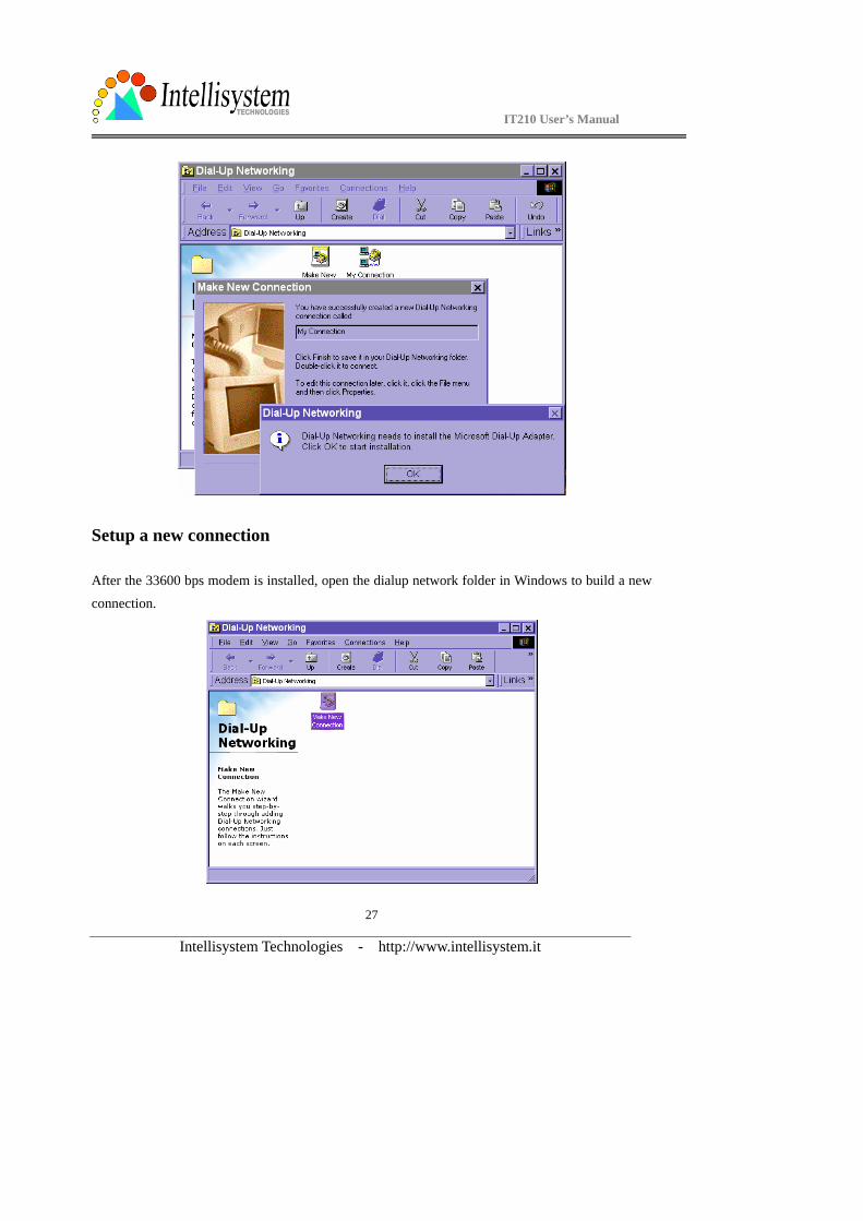
Setup a new connection
After the 33600 bps modem is installed, open the dialup network folder in Windows to build a new
connection.
IT210 User’s Manual
Intellisystem Technologies - http://www.intellisystem.it
28
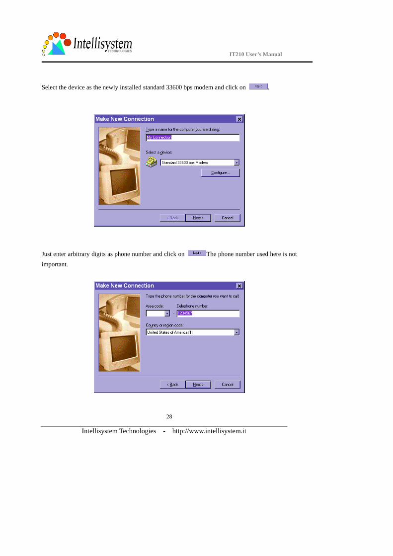
Select the device as the newly installed standard 33600 bps modem and click on .
Just enter arbitrary digits as phone number and click on The phone number used here is not important.
IT210 User’s Manual
Intellisystem Technologies - http://www.intellisystem.it
29
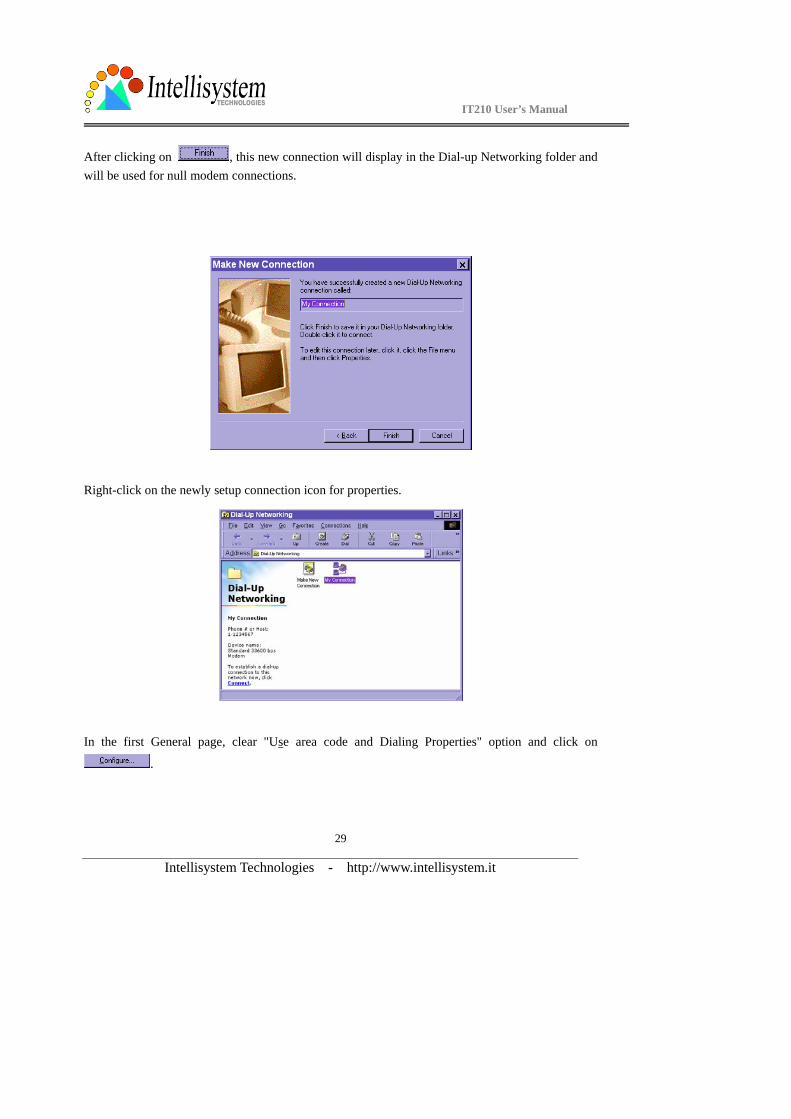
After clicking on , this new connection will display in the Dial-up Networking folder and will be used for null modem connections.
Right-click on the newly setup connection icon for properties.
In the first General page, clear "Use area code and Dialing Properties" option and click on
.
IT210 User’s Manual
Intellisystem Technologies - http://www.intellisystem.it
30
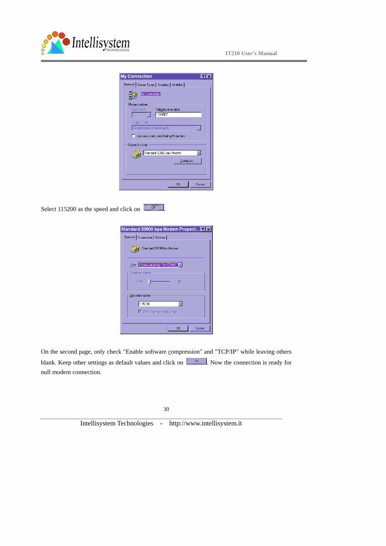
Select 115200 as the speed and click on .
On the second page, only check "Enable software compression" and "TCP/IP" while leaving others
blank. Keep other settings as default values and click on . Now the connection is ready for null modem connection.
IT210 User’s Manual
Intellisystem Technologies - http://www.intellisystem.it
31
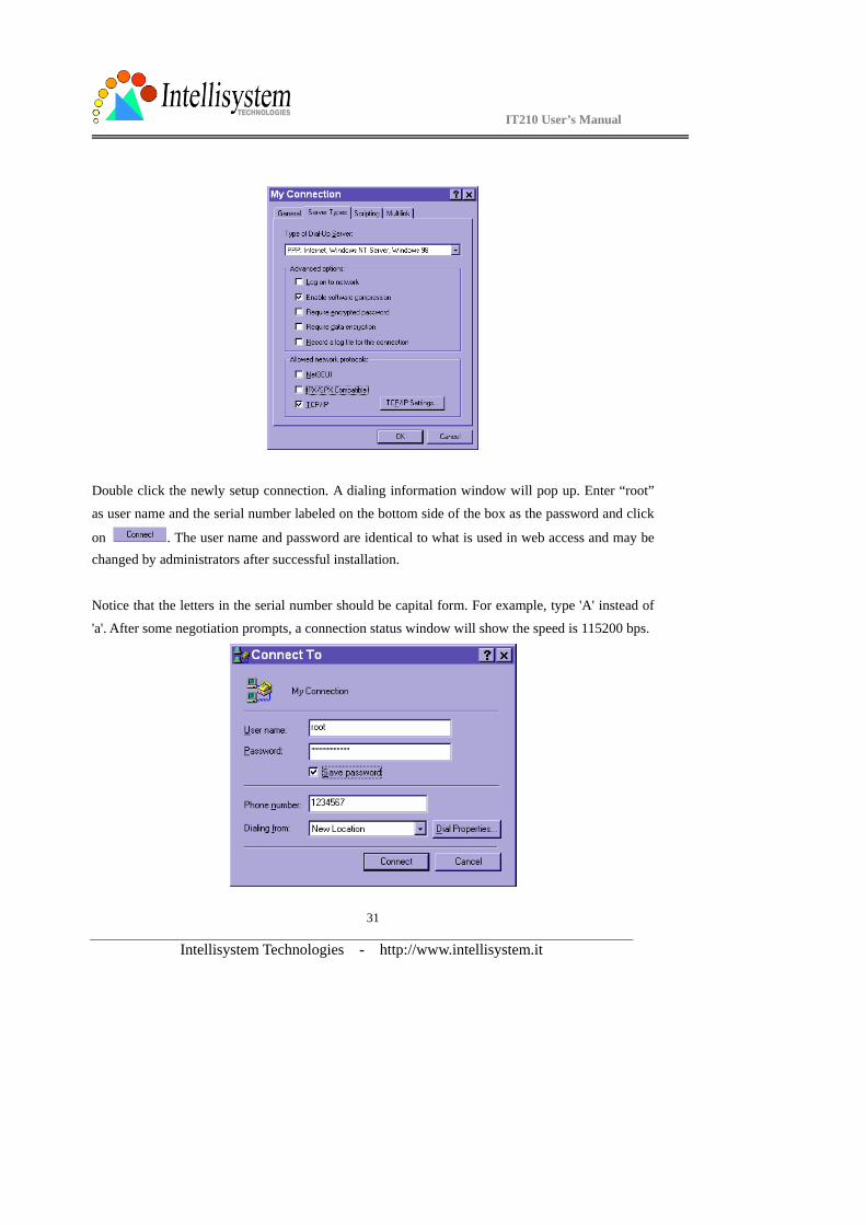
Double click the newly setup connection. A dialing information window will pop up. Enter “root”
as user name and the serial number labeled on the bottom side of the box as the password and click
on . The user name and password are identical to what is used in web access and may be changed by administrators after successful installation.
Notice that the letters in the serial number should be capital form. For example, type 'A' instead of
'a'. After some negotiation prompts, a connection status window will show the speed is 115200 bps.

IT210 User’s Manual
Intellisystem Technologies - http://www.intellisystem.it
32
After connection is established successfully, go to the next section, "First access to the IT210
Network Camera".
If an error message indicates a hardware error while connecting for the first time, especially in a Windows 2000 environment, try again to recovery the possible detection failure.
IT210 User’s Manual
Intellisystem Technologies - http://www.intellisystem.it
33
First access to the IT210 Network Camera
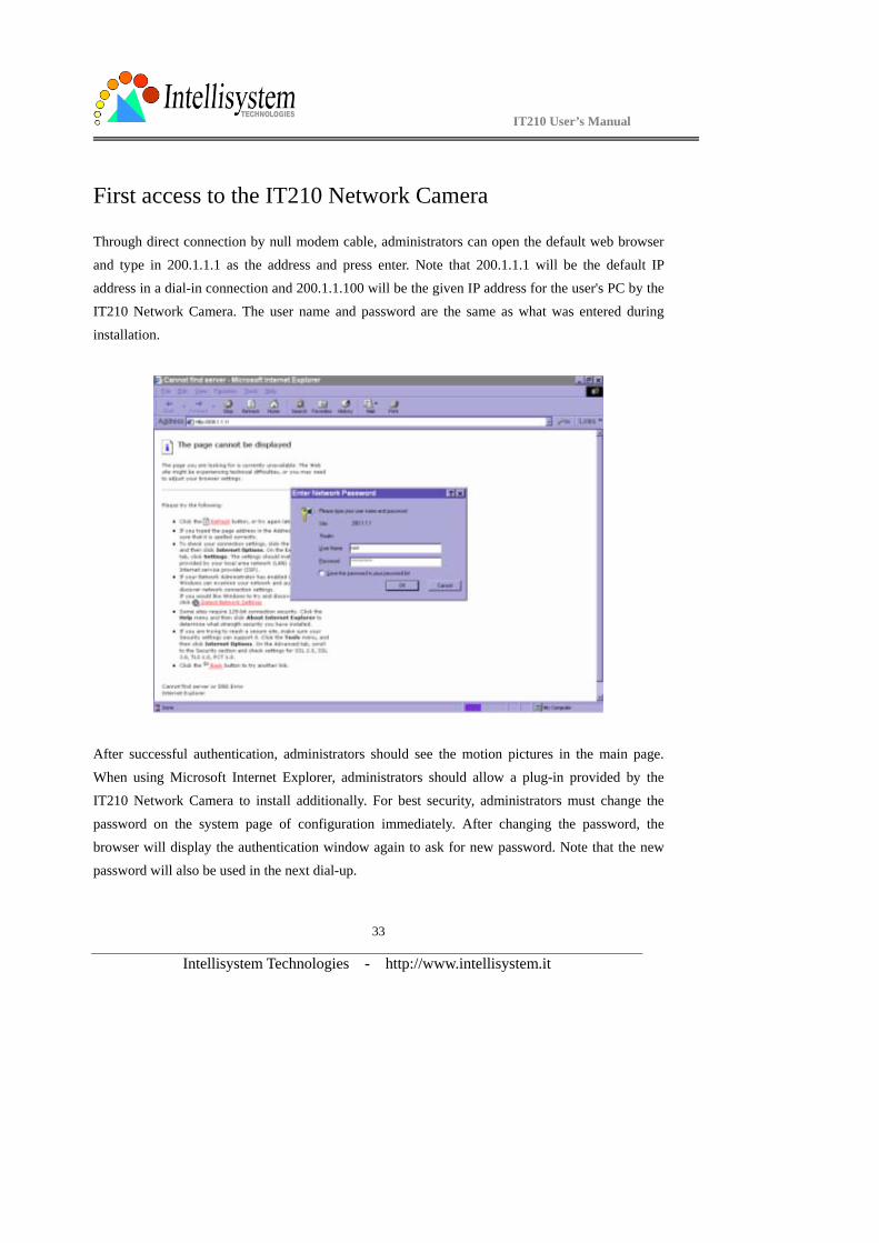
Through direct connection by null modem cable, administrators can open the default web browser
and type in 200.1.1.1 as the address and press enter. Note that 200.1.1.1 will be the default IP address in a dial-in connection and 200.1.1.100 will be the given IP address for the user's PC by the
IT210 Network Camera. The user name and password are the same as what was entered during
installation.
After successful authentication, administrators should see the motion pictures in the main page.
When using Microsoft Internet Explorer, administrators should allow a plug-in provided by the
IT210 Network Camera to install additionally. For best security, administrators must change the
password on the system page of configuration immediately. After changing the password, the browser will display the authentication window again to ask for new password. Note that the new
password will also be used in the next dial-up.
IT210 User’s Manual
Intellisystem Technologies - http://www.intellisystem.it
34
To make the IT210 Network Camera successfully work in dial-in and dial-out modes, follow the procedures below for basic configurations. If people other than administrators will be allowed to
use the IT210 Network Camera, administrators should add these user profiles in the users option.
While the IT210 Network Camera accepts dial-in connection and acts as a server, the user name and
password used in dialing are the same as what was stored in the user database managed for web access. Any managed user can be authorized during PPP negotiation and access web pages.
However only administrators can access the configuration page.
There is more information needed for correct modem operation. Refer to the modem setting section in configuration for further settings. The IT210 Network Camera will wait for someone to dial in. If
the administrator has setup some conditions in the application, the IT210 Network Camera will
automatically dial out based on the administrator's configuration. Refer to the application section in
configuration for special security applications. After everything is set and saved, turn off the IT210 Network Camera and replace the null modem cable with modem for dial-up network. Since the null
modem connection is used to configure the IT210 Network Camera in advance for modem
connection, administrators cannot connect again without restarting the system.
If dial-out configuration is activated, the IT210 Network Camera will dial out to send a system
startup log to test and drop the call after the pre-configured period.
IT210 User’s Manual
Intellisystem Technologies - http://www.intellisystem.it
35
Authentication
The IT210 Network Camera is a well-designed stand-alone network camera. With the built-in web
server, authorized users may use any popular web browser such as Internet Explorer and Netscape
Navigator to watch the video captured by the IT210 Network Camera. The powerful video
compression processes 30 frames per second and makes the scene in your browser real-time display. The high resolution CCD and high performance lens assure the best image quality. Another benefit
of web interface is that each function and each configuration has its specific URL that allows
advanced users to easily integrate them into existing software programs.
The preparation of the primary users to utilize the IT210 Network Camera is quite simple since
administrators have done the majority of the installation. Most administrators find the installation is
easy in general environments because most settings are automatically configured. Open your
familiar web browser and connect to the IT210 Network Camera just like a general web site and the video will present on demand. Make sure the web address of the IT210 Network Camera’s target is
accurate. If the image looks flickeringly, the product model may have the wrong video modulation
with your regional regulation. Please consult with your local dealer.
After opening the Web browser and typing in the URL of the IT210 Network Camera, a dialogue
window will pop up to request a username and password. For administrator’s initial usage of the
IT210 Network Camera, enter the username as “root” and the password as the serial number in
capital letters. The serial number can be found on the labels under the body of the IT210 Network Camera and the top side of the carton. The primary users will be allowed to enter as soon as the
administrator finishes adding user profiles. Upon successful authentication, the main page will be
displayed.
For demonstration purpose, enter the “Demo” page of configurations to activate the demo account.
Once the demo account is setup, any one may watch the video by using “demo” as user name while
ignoring the password. Different from managed users, the demo account has certain limitations that
IT210 User’s Manual
Intellisystem Technologies - http://www.intellisystem.it
36
are determined by administrators.
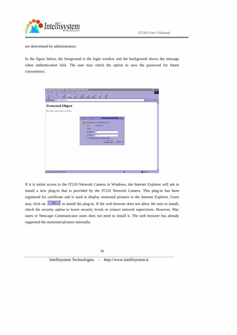
In the figure below, the foreground is the login window and the background shows the message
when authentication fails. The user may check the option to save the password for future
convenience.
If it is initial access to the IT210 Network Camera in Windows, the Internet Explorer will ask to
install a new plug-in that is provided by the IT210 Network Camera. This plug-in has been
registered for certificate and is used to display motioned pictures in the Internet Explorer. Users
may click on to install the plug-in. If the web browser does not allow the user to install, check the security option to lower security levels or contact network supervisors. However, Mac
users or Netscape Communicator users does not need to install it. The web browser has already
supported the motioned pictures internally.
IT210 User’s Manual
Intellisystem Technologies - http://www.intellisystem.it
37
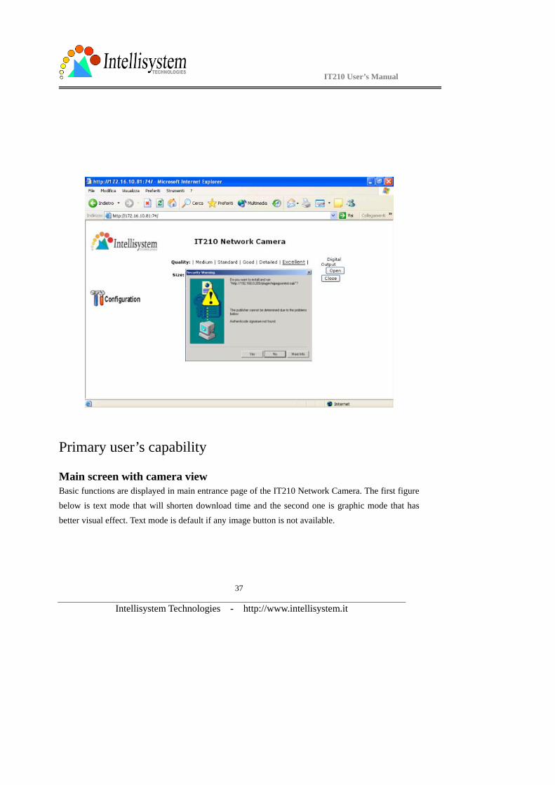
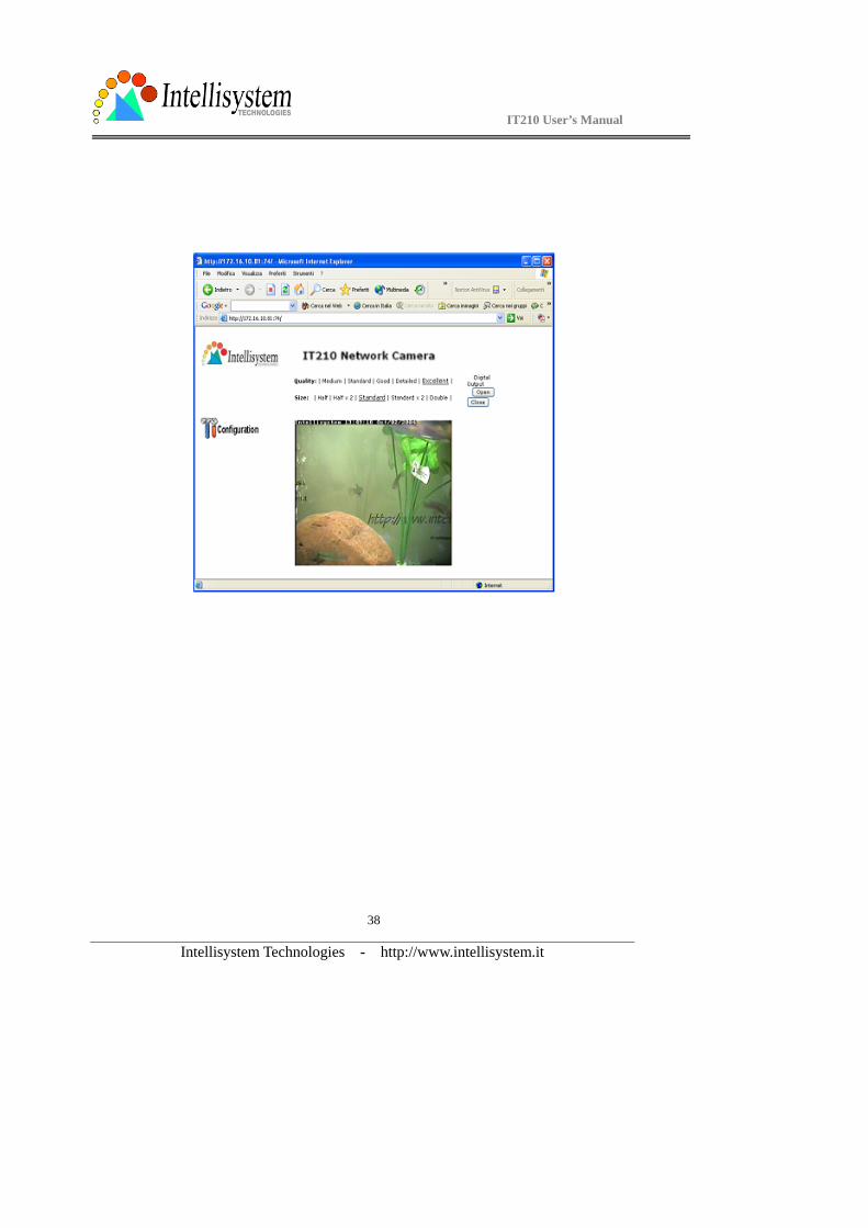
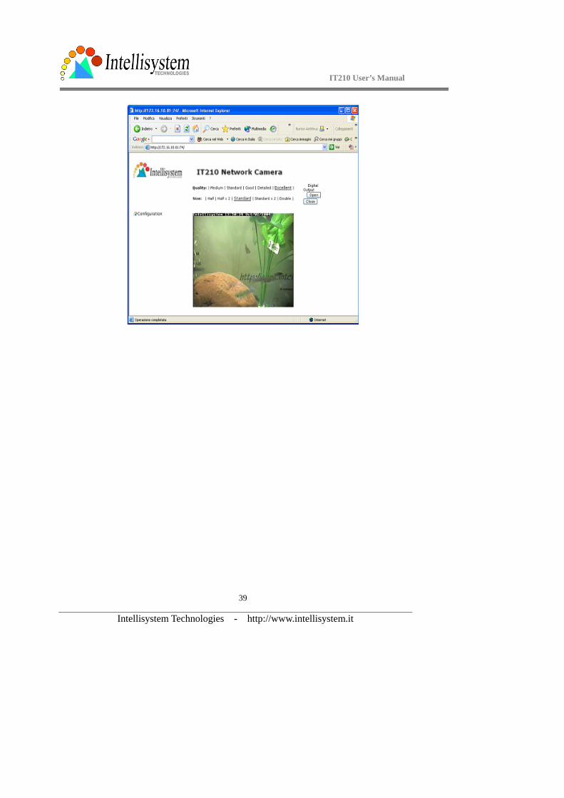
Primary user’s capability
Main screen with camera view Basic functions are displayed in main entrance page of the IT210 Network Camera. The first figure
below is text mode that will shorten download time and the second one is graphic mode that has
better visual effect. Text mode is default if any image button is not available.
IT210 User’s Manual
Intellisystem Technologies - http://www.intellisystem.it
38
IT210 User’s Manual
Intellisystem Technologies - http://www.intellisystem.it
39
IT210 User’s Manual
Intellisystem Technologies - http://www.intellisystem.it
40
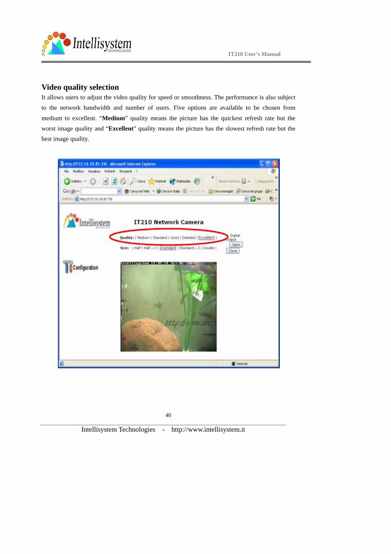
Video quality selection It allows users to adjust the video quality for speed or smoothness. The performance is also subject
to the network bandwidth and number of users. Five options are available to be chosen from
medium to excellent. “Medium” quality means the picture has the quickest refresh rate but the
worst image quality and “Excellent” quality means the picture has the slowest refresh rate but the best image quality.
IT210 User’s Manual
Intellisystem Technologies - http://www.intellisystem.it
41
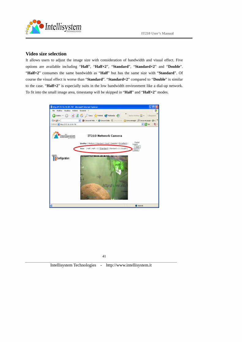
Video size selection It allows users to adjust the image size with consideration of bandwidth and visual effect. Five
options are available including “Half”, “Half×2”, “Standard”, “Standard×2” and “Double”. “Half×2” consumes the same bandwidth as “Half” but has the same size with “Standard”. Of
course the visual effect is worse than “Standard”. “Standard×2” compared to “Double” is similar
to the case. “Half×2” is especially suits in the low bandwidth environment like a dial-up network.
To fit into the small image area, timestamp will be skipped in “Half” and “Half×2” modes.
IT210 User’s Manual
Intellisystem Technologies - http://www.intellisystem.it
42
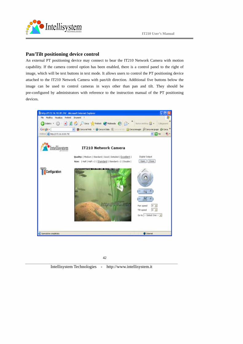
Pan/Tilt positioning device control An external PT positioning device may connect to bear the IT210 Network Camera with motion
capability. If the camera control option has been enabled, there is a control panel to the right of
image, which will be text buttons in text mode. It allows users to control the PT positioning device attached to the IT210 Network Camera with pan/tilt direction. Additional five buttons below the
image can be used to control cameras in ways other than pan and tilt. They should be
pre-configured by administrators with reference to the instruction manual of the PT positioning
devices.
IT210 User’s Manual
Intellisystem Technologies - http://www.intellisystem.it
43
System configuration
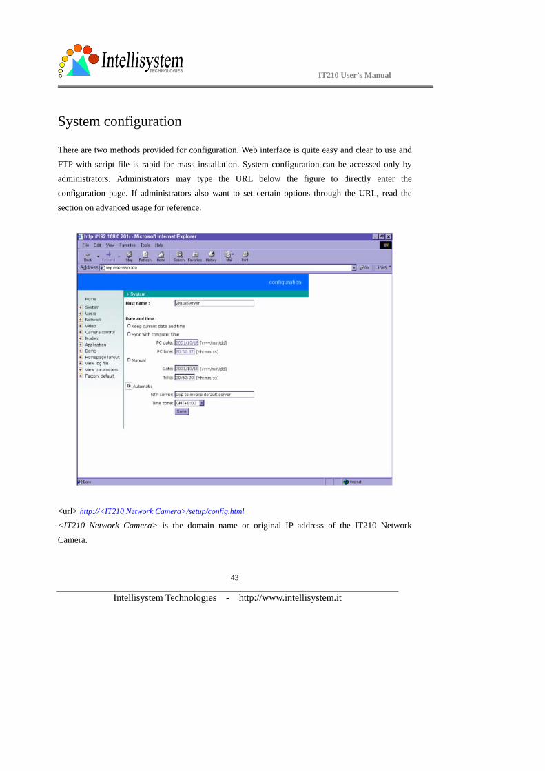
There are two methods provided for configuration. Web interface is quite easy and clear to use and
FTP with script file is rapid for mass installation. System configuration can be accessed only by administrators. Administrators may type the URL below the figure to directly enter the
configuration page. If administrators also want to set certain options through the URL, read the
section on advanced usage for reference.
<url> http://<IT210 Network Camera>/setup/config.html <IT210 Network Camera> is the domain name or original IP address of the IT210 Network
Camera.
IT210 User’s Manual
Intellisystem Technologies - http://www.intellisystem.it
44
System parameters
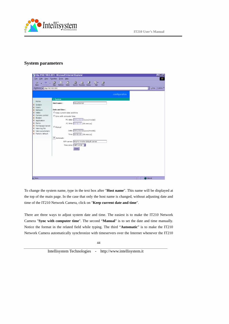
To change the system name, type in the text box after "Host name". This name will be displayed at the top of the main page. In the case that only the host name is changed, without adjusting date and
time of the IT210 Network Camera, click on "Keep current date and time".
There are three ways to adjust system date and time. The easiest is to make the IT210 Network
Camera "Sync with computer time". The second “Manual” is to set the date and time manually.
Notice the format in the related field while typing. The third “Automatic” is to make the IT210 Network Camera automatically synchronize with timeservers over the Internet whenever the IT210
IT210 User’s Manual
Intellisystem Technologies - http://www.intellisystem.it
45
Network Camera starts up. It may fail if the assigned NTP server cannot be reached or it is within a local network. Leaving the NTP server blank will let the IT210 Network Camera connect to default
timeservers or type in assigned NTP server. Domain name or IP address format is acceptable as
long as DNS server is available. Do not forget to set the "Time zone" offset for local settings. It
only affects the hour in NTP method. Click on to validate changes.
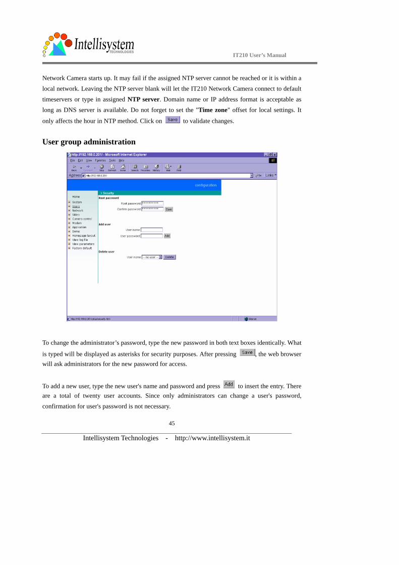
User group administration
To change the administrator’s password, type the new password in both text boxes identically. What
is typed will be displayed as asterisks for security purposes. After pressing , the web browser will ask administrators for the new password for access.
To add a new user, type the new user's name and password and press to insert the entry. There are a total of twenty user accounts. Since only administrators can change a user's password,
confirmation for user's password is not necessary.
IT210 User’s Manual
Intellisystem Technologies - http://www.intellisystem.it
46
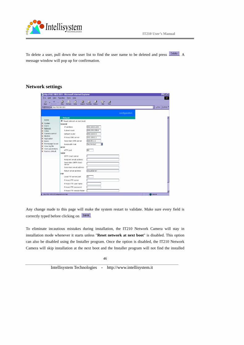
To delete a user, pull down the user list to find the user name to be deleted and press . A message window will pop up for confirmation.
Network settings
Any change made to this page will make the system restart to validate. Make sure every field is
correctly typed before clicking on .
To eliminate incautious mistakes during installation, the IT210 Network Camera will stay in
installation mode whenever it starts unless "Reset network at next boot" is disabled. This option can also be disabled using the Installer program. Once the option is disabled, the IT210 Network
Camera will skip installation at the next boot and the Installer program will not find the installed

IT210 User’s Manual
Intellisystem Technologies - http://www.intellisystem.it
47
units. That implies that the IT210 Network Camera cannot be accessed if no one remembers the IP address, except by restoring factory default settings. However, with this option disabled the IT210
Network Camera can automatically operate normally after restarting in case of losing power. This
option is ignored in the PPP connection.
Administrators may modify the network settings to fit into existing networks. Some broadband
service subnet mask may differ from the default value 255.255.255.0 and service providers may
assign some specific network settings. Administrators should change the configuration
according to what is given by the service provider. The configuration may include "IP address",
"Subnet mask", "Default router", "Primary DNS server" and "Secondary DNS server". After
changing network settings, be sure to leave "Reset network at next boot" blank to skip next installation when the system restarts. Otherwise the settings will be erased.
Each IT210 Network Camera can be limited in bandwidth by administrators according to its
priority and importance of location. "Bandwidth limit" is most useful to balance network utilization when multiple IT210 Network Cameras are installed in the same network. It is more
effective than changing image quality only and achieves better performance with adequate image size and quality. Keeping the value as zero means no limitation on bandwidth utilization.
For security or network integration, administrators also can hide the server from the general HTTP
port by changing "HTTP port" to other than 80. “Local FTP server port” can also be changed to other than default port number 21. Administrators should have enough network knowledge to
change the default port.
The IT210Network Camera not only plays the role of server, it will also actively connect to servers outside to send out messages or snapshots. When the IT210 Network Camera starts, it will send out
a system log to notify the administrator. Even in modem application, the IT210 Network Camera
will send out a connection log whenever it dials out to an ISP or dialup server outside. If the
administrator has setup some applications in either event mode or sequential mode, the IT210 Network Camera will send out snapshots once conditions are met. There are two methods to send
files, including e-mail and FTP. To ensure the IT210 Network Camera sends out files correctly,
administrators should set valid "SMTP (mail) server" and "Recipient email address" as well as
IT210 User’s Manual
Intellisystem Technologies - http://www.intellisystem.it
48
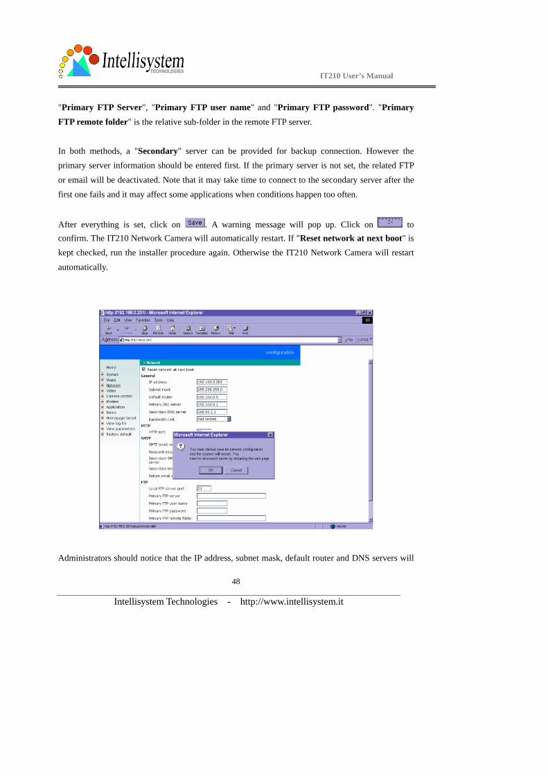
"Primary FTP Server", "Primary FTP user name" and "Primary FTP password". "Primary
FTP remote folder" is the relative sub-folder in the remote FTP server.
In both methods, a "Secondary" server can be provided for backup connection. However the primary server information should be entered first. If the primary server is not set, the related FTP or email will be deactivated. Note that it may take time to connect to the secondary server after the
first one fails and it may affect some applications when conditions happen too often.
After everything is set, click on . A warning message will pop up. Click on to confirm. The IT210 Network Camera will automatically restart. If "Reset network at next boot" is kept checked, run the installer procedure again. Otherwise the IT210 Network Camera will restart
automatically.
Administrators should notice that the IP address, subnet mask, default router and DNS servers will

IT210 User’s Manual
Intellisystem Technologies - http://www.intellisystem.it
49
be cleared when the network interface is switched to the other. Refer to the related section of Ethernet or modem for software installation.
IT210 User’s Manual
Intellisystem Technologies - http://www.intellisystem.it
50
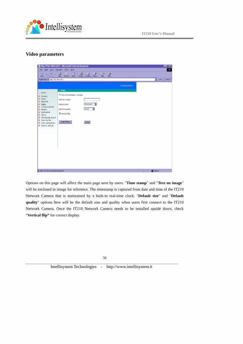
Video parameters
Options on this page will affect the main page seen by users. "Time stamp" and "Text on image" will be enclosed in image for reference. The timestamp is captured from date and time of the IT210
Network Camera that is maintained by a built-in real-time clock. "Default size" and "Default quality" options here will be the default size and quality when users first connect to the IT210 Network Camera. Once the IT210 Network Camera needs to be installed upside down, check
“Vertical flip” for correct display.

IT210 User’s Manual
Intellisystem Technologies - http://www.intellisystem.it
51
To adjust image settings for best visual quality, press and a motion picture window will pop up for your reference. There are four fields including "Brightness", "Contrast",
"Hue" and "Saturation" for video compensation. . Each field has eleven levels ranged from -5 to
+5. The user may press to fine-tune the image. When the image is O.K., press to
memorize the image settings or to recall the original settings. If parameters are changed without saving, they will be used until the next system startup.
IT210 User’s Manual
Intellisystem Technologies - http://www.intellisystem.it
52
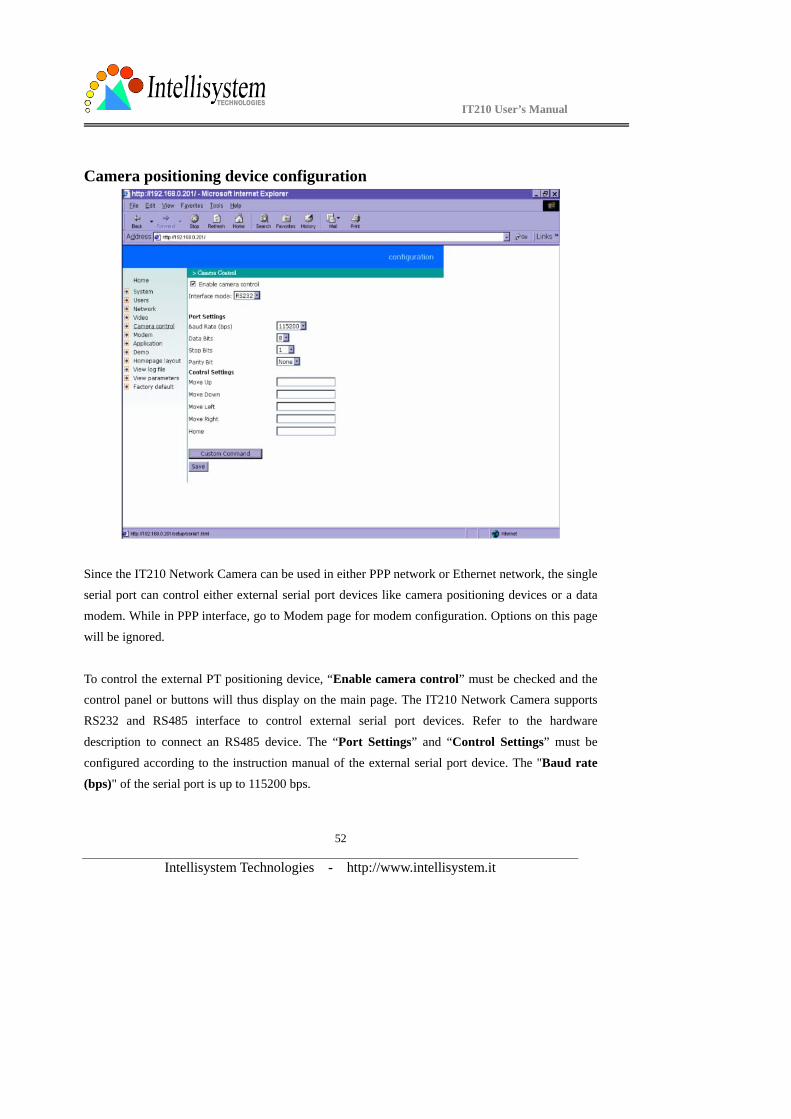
Camera positioning device configuration
Since the IT210 Network Camera can be used in either PPP network or Ethernet network, the single serial port can control either external serial port devices like camera positioning devices or a data
modem. While in PPP interface, go to Modem page for modem configuration. Options on this page
will be ignored.
To control the external PT positioning device, “Enable camera control” must be checked and the control panel or buttons will thus display on the main page. The IT210 Network Camera supports
RS232 and RS485 interface to control external serial port devices. Refer to the hardware
description to connect an RS485 device. The “Port Settings” and “Control Settings” must be
configured according to the instruction manual of the external serial port device. The "Baud rate
(bps)" of the serial port is up to 115200 bps.
IT210 User’s Manual
Intellisystem Technologies - http://www.intellisystem.it
53
The commands in "Control settings" should be edited in ASCII format. The IT210 Network Camera will interpret the ASCII format command to binary string. For instance, “012000ABCD”
will be sent out of the COM port as five hexadecimal bytes of 01, 20, 00, AB and CD. If the
command string
is composed of two or more commands, a comma ‘,’ should be inserted to separate each command.
Each comma represents 200 milliseconds. For instance, a command to pan left may be “01000305”
and a command to stop panning may be “01000300”. The user may edit the applicable command as
“01000305,01000300” in the “Move Left” field. This means the camera will pan left for 200 milliseconds. The maximal length of a command string is 60 which is equivalent to 30 hexadecimal
bytes. When everything is set, click on to save the commands and click on to close the command setting window.
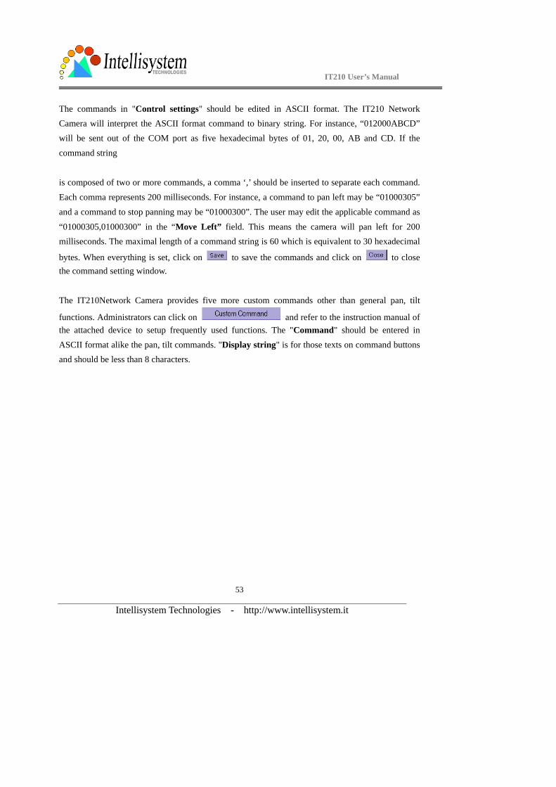
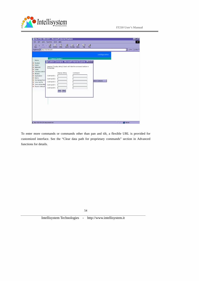
The IT210Network Camera provides five more custom commands other than general pan, tilt
functions. Administrators can click on and refer to the instruction manual of the attached device to setup frequently used functions. The "Command" should be entered in ASCII format alike the pan, tilt commands. "Display string" is for those texts on command buttons and should be less than 8 characters.
IT210 User’s Manual
Intellisystem Technologies - http://www.intellisystem.it
54
To enter more commands or commands other than pan and tilt, a flexible URL is provided for
customized interface. See the “Clear data path for proprietary commands” section in Advanced
functions for details.
IT210 User’s Manual
Intellisystem Technologies - http://www.intellisystem.it
55
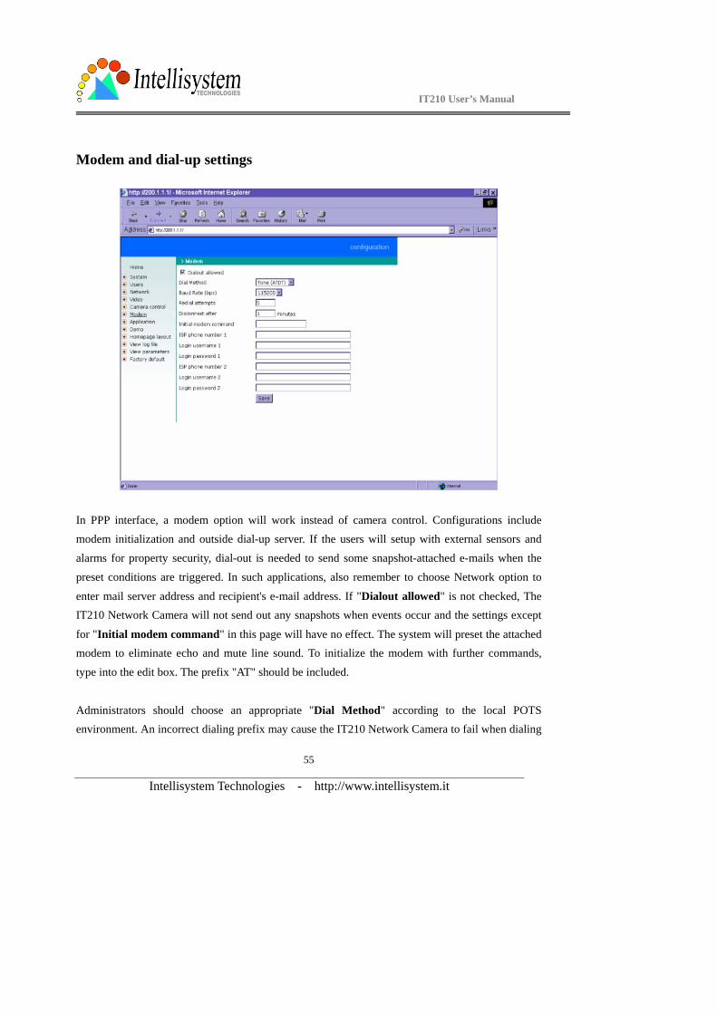
Modem and dial-up settings
In PPP interface, a modem option will work instead of camera control. Configurations include modem initialization and outside dial-up server. If the users will setup with external sensors and
alarms for property security, dial-out is needed to send some snapshot-attached e-mails when the
preset conditions are triggered. In such applications, also remember to choose Network option to
enter mail server address and recipient's e-mail address. If "Dialout allowed" is not checked, The IT210 Network Camera will not send out any snapshots when events occur and the settings except
for "Initial modem command" in this page will have no effect. The system will preset the attached modem to eliminate echo and mute line sound. To initialize the modem with further commands,
type into the edit box. The prefix "AT" should be included.
Administrators should choose an appropriate "Dial Method" according to the local POTS environment. An incorrect dialing prefix may cause the IT210 Network Camera to fail when dialing

IT210 User’s Manual
Intellisystem Technologies - http://www.intellisystem.it
56
out. "Redial attempts" means how many times the IT210 Network Camera should try to connect to
each ISP. Setting the value in "Disconnect after minutes" will force the IT210 Network Camera to drop the connection when there is no activity on the connection for the specific period. The range of
this period is from 1 to 240 minutes, with 0 indicating a continuous connection. Administrators may
let the IT210 Network Camera keep the connection for a while to allow connections from outside. The IP address given by the ISP can be taken from the connection log that is mailed or uploaded
when dial-up connection is successful. Setting the value to zero will make the IT210 Network
Camera always keep the connection.
Based on the settings of DI/DO in the application, the system will send mails or upload via FTP
with image attachment upon the event occurring. In that case the IT210 Network Camera will need
a network connection and automatically dial out to the pre-configured server outside. When a
connection is successfully established, the IT210 Network Camera will send out a connection log to notify given network settings. For those installations that may switch the network interface between
Ethernet and PPP, administrators should notice that the settings of FTP or SMTP servers might be
different from what are in an Ethernet environment. If the network interface is changed,
administrators may need to configure them in advance.
The IT210 Network Camera will try the second ISP as a backup when the first ISP fails and exceeds
the redial attempts. "ISP phone number" should be the complete phone number including country code and area code if necessary. "Login username" and "Login password" are used to pass the PPP negotiation requested by the ISP server. Note that the pair of login name and password is
dependent on the ISP and is different from what is used in the authentication process in web access.
IT210 User’s Manual
Intellisystem Technologies - http://www.intellisystem.it
57
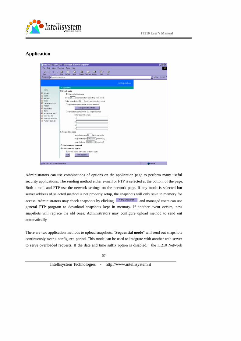
Application
Administrators can use combinations of options on the application page to perform many useful security applications. The sending method either e-mail or FTP is selected at the bottom of the page.
Both e-mail and FTP use the network settings on the network page. If any mode is selected but
server address of selected method is not properly setup, the snapshots will only save in memory for
access. Administrators may check snapshots by clicking and managed users can use general FTP program to download snapshots kept in memory. If another event occurs, new
snapshots will replace the old ones. Administrators may configure upload method to send out
automatically.
There are two application methods to upload snapshots. "Sequential mode" will send out snapshots continuously over a configured period. This mode can be used to integrate with another web server
to serve overloaded requests. If the date and time suffix option is disabled, the IT210 Network

IT210 User’s Manual
Intellisystem Technologies - http://www.intellisystem.it
58
Camera can use FTP to upload and overwrite snapshot files periodically. The remote folder of snapshot files for FTP can be configured on the network page. The snapshot period is between
"Snapshot begin" and "Snapshot end" and it will repeat everyday. The snapshot interval is set
among 1 to 999 in "Snapshot every tenth seconds" and thus the minimal interval can be 0.1 second.
The other "Event mode" can be used to combine motion detection with devices attached to the digital input, to drive the device attached to the digital output, or send out snapshots for evidence. It
helps users to establish an all-purpose security system. Both or either one of motion detection and matched I/O scripts will trigger the IT210 Network Camera to snapshot three stages of events and
send them to server outside. The IT210 Network Camera will continuously monitor the video
channel every half second. If any event occurs, the IT210 Network Camera will keep the previous
snapshot and current snapshot in memory and take another snapshot after certain delay set in "Take
snapshot at tenth seconds after event" by the administrator. Three stages of snapshots will be VPRE.JPG, VTRG.JPG and VPOS.JPG. Since the same event may exist for a while, administrators
can set delay time in "Delay seconds before detecting next event" to reduce multiple triggers by the same event. To ensure correct snapshots of events, the value cannot be shorter than the delay of
"Take snapshot at tenth seconds after event".
Note that "Event mode" should be checked in advance to enable event trigger application. Furthermore, "Upload snapshot while motion detected" and/or "Upload snapshot while I/O
script matched" should be checked with to work. If neither upload condition is checked, "Event
mode" will be cleared even if the administrator has checked it previously. Similarly, if "Event
mode" is not checked, any upload condition will be cleared no matter the administrator has checked them or not. Only upload condition is checked as well as "Event mode" is checked will make the IT210 Network Camera check the condition in real time.
If motion detection is enabled or extended I/O scripts are edited, administrators can click on "Show alert in image" to display the event status in upper-right corner of image. It will be white character with red background. "M" means motion is detected while "1" to " 4" mean matched I/O script
number "1" to "4". If neither mode is checked, "Show alert in image" combined with motion detection and/or I/O script still works for indication. To integrate with external recorder software,
IT210 User’s Manual
Intellisystem Technologies - http://www.intellisystem.it
59
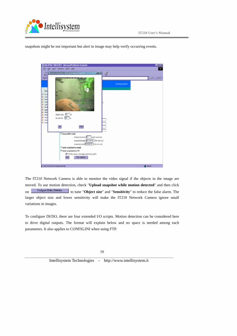
snapshots might be not important but alert in image may help verify occurring events.
The IT210 Network Camera is able to monitor the video signal if the objects in the image are
moved. To use motion detection, check "Upload snapshot while motion detected" and then click
on to tune "Object size" and "Sensitivity" to reduce the false alarm. The larger object size and lower sensitivity will make the IT210 Network Camera ignore small variations in images.
To configure DI/DO, there are four extended I/O scripts. Motion detection can be considered here
to drive digital outputs. The format will explain below and no space is needed among each parameters. It also applies to CONFIG.INI when using FTP.
IT210 User’s Manual
Intellisystem Technologies - http://www.intellisystem.it
60
<command format> [“Digital input number”“Digital input state”][“operator”“Digital input number”“Digital input
state”…] [“operator”{“hour”:“minute”:“second”}…][“operator”“M”]=“Digital output
number”“Digital output state”
<parameter explanation>
Item between [ and ] means optional but at least one should be checking condition.
“Digital input number”: 1 ~ 4 “Digital input state”: H (high), L (low), / (low to high), \ (high to low)
“operator”: + (OR), * (AND)
{“hour”:”minute”:”second”}: set a time alarm repeats everyday. "hour" set to 24 will check
"minute":"second" every hour. "minute" set to 60 will check "second" every minute.
“M”: motion detection event. Note that "Upload snapshot while motion
detected" should be set in advance.
“Digital output number”: 1 ~ 2 “Digital output state”: H (NC), L (NO)
<example> {17:30:00}+M=1H will set NC of SW1 to short with COMMON after 17:30 or any motion is
detected.
1H*2\+{8:30:00}=1L will set NO of SW1 to short with COMMON after 8:30 or DI1 high companied with DI2 transient from high to low.
Note that "Upload snapshot while I/O script matched" should be checked in advance to enable function.
IT210 User’s Manual
Intellisystem Technologies - http://www.intellisystem.it
61
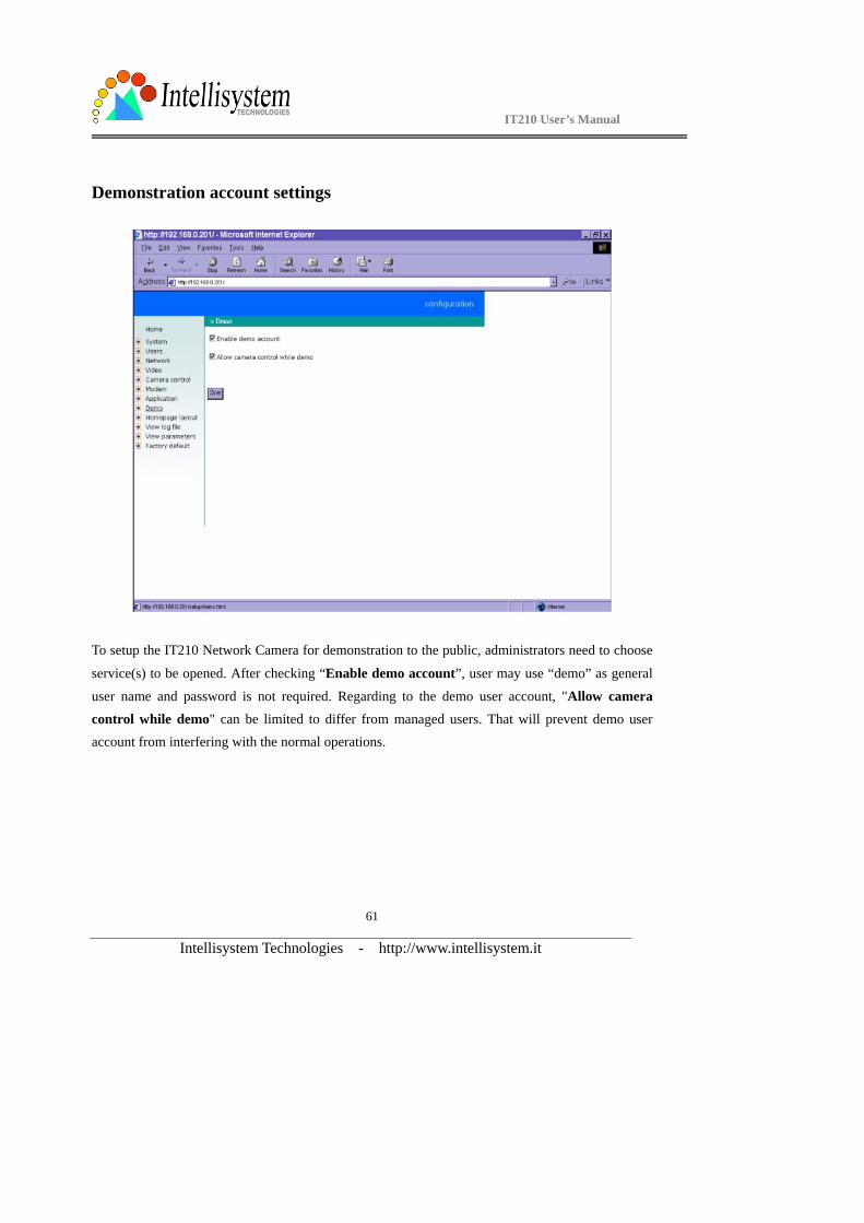
Demonstration account settings
To setup the IT210 Network Camera for demonstration to the public, administrators need to choose
service(s) to be opened. After checking “Enable demo account”, user may use “demo” as general
user name and password is not required. Regarding to the demo user account, "Allow camera control while demo" can be limited to differ from managed users. That will prevent demo user account from interfering with the normal operations.
IT210 User’s Manual
Intellisystem Technologies - http://www.intellisystem.it
62
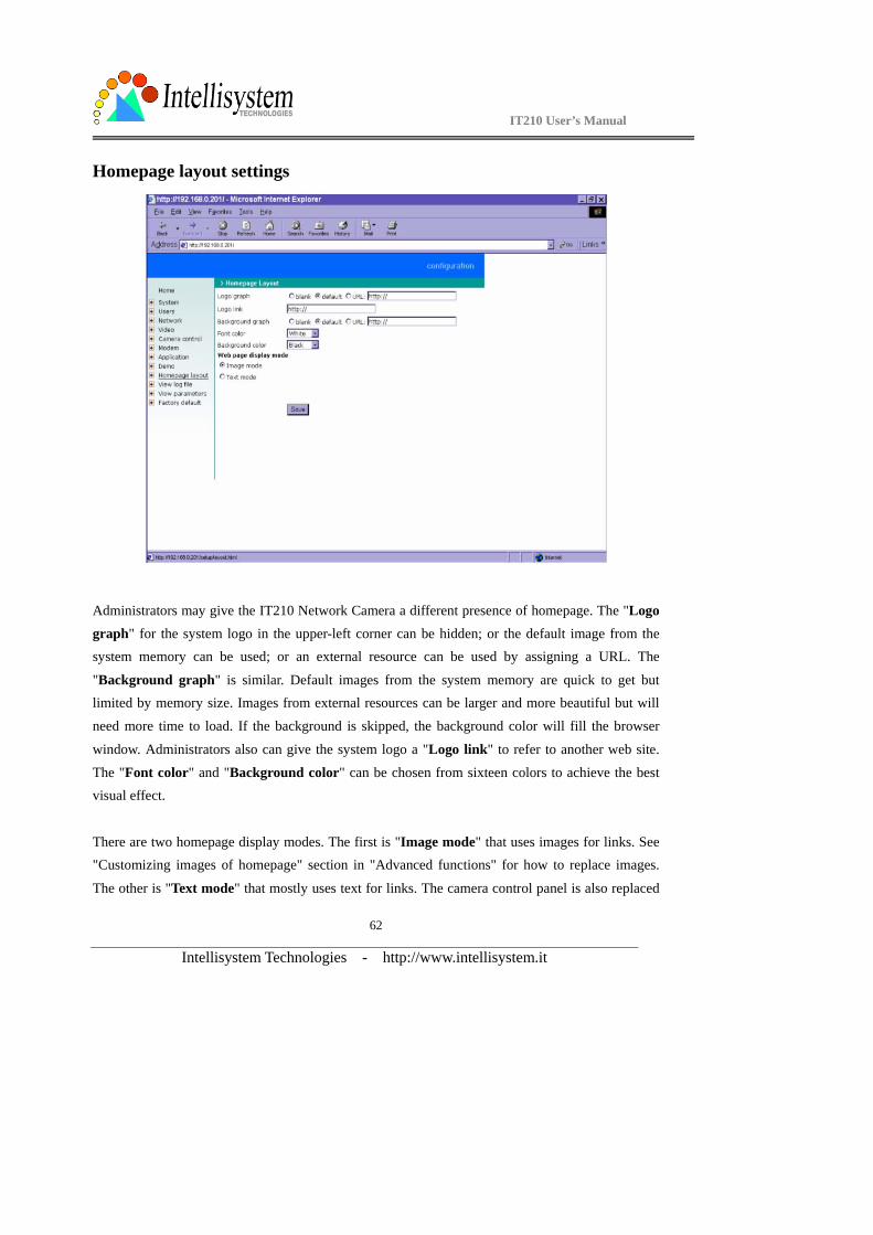
Homepage layout settings
Administrators may give the IT210 Network Camera a different presence of homepage. The "Logo graph" for the system logo in the upper-left corner can be hidden; or the default image from the system memory can be used; or an external resource can be used by assigning a URL. The
"Background graph" is similar. Default images from the system memory are quick to get but limited by memory size. Images from external resources can be larger and more beautiful but will
need more time to load. If the background is skipped, the background color will fill the browser
window. Administrators also can give the system logo a "Logo link" to refer to another web site.
The "Font color" and "Background color" can be chosen from sixteen colors to achieve the best visual effect.
There are two homepage display modes. The first is "Image mode" that uses images for links. See "Customizing images of homepage" section in "Advanced functions" for how to replace images.
The other is "Text mode" that mostly uses text for links. The camera control panel is also replaced
IT210 User’s Manual
Intellisystem Technologies - http://www.intellisystem.it
63
by text buttons below the image.
One-shot fast configuration via FTP For quick setup of the IT210 Network Camera, the administrator can utilize the default
CONFIG.INI that may be downloaded from the FTP daemon of the IT210 Network Camera. To log
into the FTP daemon, enter “root” as the user name and the same password used when connecting to the Web server. The serial number of the IT210 Network Camera is the password for the initial
access.
Then administrators only need to modify necessary fields and then upload the file to the IT210 Network Camera with the file name “CONFIG.INI”. To reduce error in interpretation, it is
recommended that the downloaded template CONFIG.INI be modified using the options following
each item in the sample below. The file will include seven categories: [SYSTEM], [NETWORK],
[VIDEO], [SERIAL1], [SERIAL2], [DIDO], and [DEMO]. The category name in brackets should be in upper case. The item name in angle braces should be in lower case. Some items related to
disable/enable should use the keywords “YES”/“NO”. The number zero entry in <user name> and
<user password> is for administrators, i.e. “root”.
Since the password when logging into FTP is not encrypted, it is recommended to use Web instead
of FTP to configure the system afterwards. If some parameters other than the network or camera
drivers are changed, administrators can set <reset system> to NO to avoid resetting the system. It
will automatically return to YES during the next downloading of CONFIG.INI.
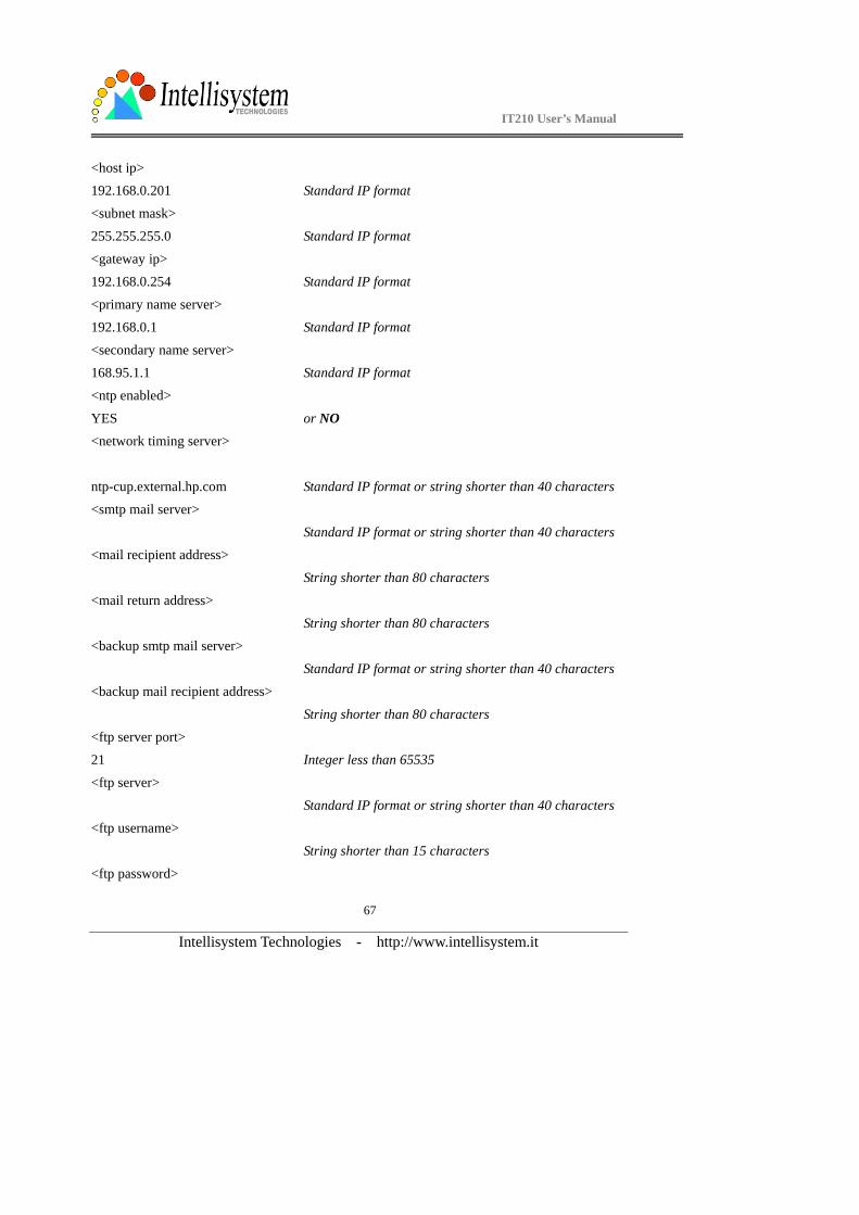
A sample CONFIG.INI is attached below. The italic text following each line describes the format of
the field and the bold italic characters are the possible values of each field. ******* sample file **********
IT210 Network Camera Initial Configuration File
[SYSTEM] <reset system>
YES Reset system after reading CONFIG.INI or NO <host name>
IT210 User’s Manual
Intellisystem Technologies - http://www.intellisystem.it
64
IT210 Network Camera String no more than 38 characters <serial number>
0002D1000001 Read only string
<software version>
IT210-5168-0100 Read only string
<current date>
2004/08/14 year/month/date. Read only string
<current time> 07:00:00 hour/minute/second. Read only string
<time zone>
0 From 12 to -12 <user name> (0) root Read only string
(1) String shorter than 15 characters
(2) The followings are as same as above
(3) (4)
(5)
(6)
(7) (8)
(9)
(10)
(11) (12)
(13)
(14)
(15) (16)
(17)
(18)

IT210 User’s Manual
Intellisystem Technologies - http://www.intellisystem.it
65
(19) (20)
<user password>
(0) 0002D1000001 Initial value is as same as serial number
(1) String shorter than 15 characters (2) The followings are as same as above
(3)
(4) (5)
(6)
(7)
(8) (9)
(10)
(11)
(12) (13)
(14)
(15)
(16) (17)
(18)
(19)
(20)
[LAYOUT]
<layout type>
0 text mode or 1 for image mode <font color>
1 color index: 0 for black, 1 for white, 2 for green,
<link color> 3 for maroon, 4 for olive, 5 for navy, 6 for purple,
IT210 User’s Manual
Intellisystem Technologies - http://www.intellisystem.it
66
14 7 for gray, 8 for yellow, 9 for lime, 10 for aqua,
<background color> 11 for fuchsia, 12 for silver, 13 for red, 14 for blue,
0 15 for teal <logo type>
1 0 for blank, 1 for default image or 2 for loading from URL <background type>
1 0 for blank, 1 for default image or 2 for loading from URL <logo source>
http:// link to external resource when logo type is 2, no longer than
80 <background source>
http:// link when background type is 2, no longer than 80
<logo link>
http:// providing external link when clicking on logo, no longer than 80
<com speedlink name>
(0)AT on/of no longer than 8 characters
(1)AT bg/ed no longer than 8 characters (2)AT mode no longer than 8 characters
(3)bklt on no longer than 8 characters
(4)bklt off no longer than 8 characters
[NETWORK]
<install enabled>
YES or NO <ppp enabled> YES obsolete
<ethernet address>
00-02-D1-00-00-01 Read only string
IT210 User’s Manual
Intellisystem Technologies - http://www.intellisystem.it
67
<host ip> 192.168.0.201 Standard IP format
<subnet mask>
255.255.255.0 Standard IP format
<gateway ip> 192.168.0.254 Standard IP format
<primary name server>
192.168.0.1 Standard IP format
<secondary name server> 168.95.1.1 Standard IP format
<ntp enabled>
YES or NO <network timing server>
ntp-cup.external.hp.com Standard IP format or string shorter than 40 characters
<smtp mail server>
Standard IP format or string shorter than 40 characters <mail recipient address>
String shorter than 80 characters
<mail return address>
String shorter than 80 characters <backup smtp mail server>
Standard IP format or string shorter than 40 characters
<backup mail recipient address>
String shorter than 80 characters <ftp server port>
21 Integer less than 65535
<ftp server>
Standard IP format or string shorter than 40 characters <ftp username>
String shorter than 15 characters
<ftp password>
IT210 User’s Manual
Intellisystem Technologies - http://www.intellisystem.it
68
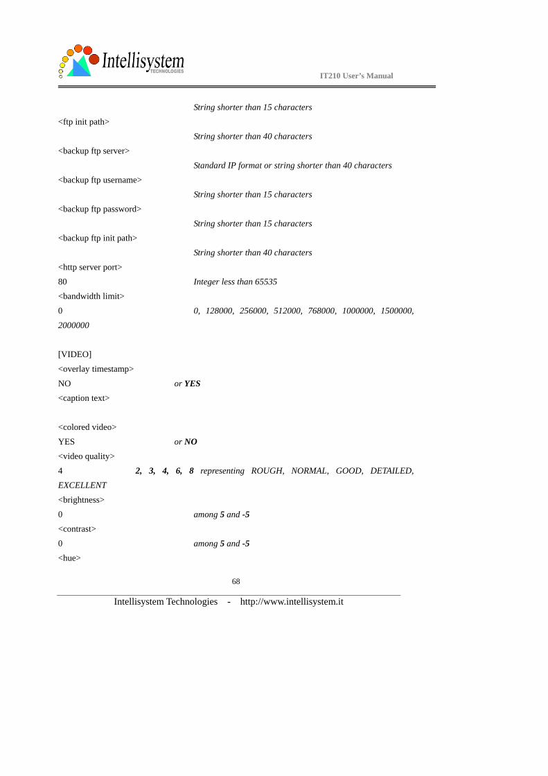
String shorter than 15 characters <ftp init path>
String shorter than 40 characters
<backup ftp server>
Standard IP format or string shorter than 40 characters <backup ftp username>
String shorter than 15 characters
<backup ftp password>
String shorter than 15 characters <backup ftp init path>
String shorter than 40 characters
<http server port>
80 Integer less than 65535 <bandwidth limit>
0 0, 128000, 256000, 512000, 768000, 1000000, 1500000,
2000000
[VIDEO]
<overlay timestamp>
NO or YES <caption text>
<colored video>
YES or NO <video quality>
4 2, 3, 4, 6, 8 representing ROUGH, NORMAL, GOOD, DETAILED, EXCELLENT
<brightness>
0 among 5 and -5 <contrast>
0 among 5 and -5 <hue>
IT210 User’s Manual
Intellisystem Technologies - http://www.intellisystem.it
69
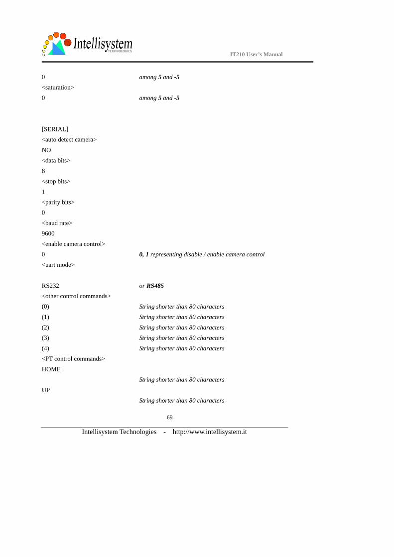
0 among 5 and -5 <saturation>
0 among 5 and -5
[SERIAL]
<auto detect camera>
NO
<data bits> 8
<stop bits>
1
<parity bits> 0
<baud rate>
9600
<enable camera control>
0 0, 1 representing disable / enable camera control <uart mode>
RS232 or RS485 <other control commands>
(0) String shorter than 80 characters
(1) String shorter than 80 characters
(2) String shorter than 80 characters (3) String shorter than 80 characters
(4) String shorter than 80 characters
<PT control commands>
HOME String shorter than 80 characters
UP
String shorter than 80 characters

IT210 User’s Manual
Intellisystem Technologies - http://www.intellisystem.it
70
DOWN String shorter than 80 characters
LEFT
String shorter than 80 characters
RIGHT String shorter than 80 characters
[ALERT]
<snapshot channel enabled>
(0)YES or NO <application mode>
0 for none, 1 for sequential mode, 2 for motion event, 4 for I/O
event <visual alert>
NO or YES, to show alert in image <upload method>
0 0 for FTP, 1 for email <file with time suffix>
YES or NO <tenth seconds to snapshot after event>
0 <percentage of object size over screen>
10 0 ~ 100, but 0 and 100 will make no sense <percentage of sensitivity>
95 0 ~ 100, but 0 and 100 will make no sense <tenth seconds to snapshot periodically>
0
<time to start snapshot> 00:00:00 24 hours format
<time to stop snapshot>
00:00:00 24 hours format
IT210 User’s Manual
Intellisystem Technologies - http://www.intellisystem.it
71
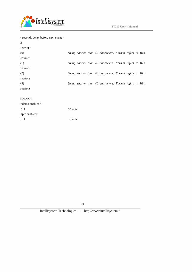
<seconds delay before next event> 3
<script>
(0) String shorter than 40 characters. Format refers to Web
sections (1) String shorter than 40 characters. Format refers to Web
sections
(2) String shorter than 40 characters. Format refers to Web
sections (3) String shorter than 40 characters. Format refers to Web
sections
[DEMO] <demo enabled>
NO or YES <ptz enabled>
NO or YES
IT210 User’s Manual
Intellisystem Technologies - http://www.intellisystem.it
72
Advanced functions
Alarm settings The IT210 Network Camera provides flexible interfaces to cover most surveillance applications. By easy script programming user can utilize up to four sensors with any signal pattern to monitor the
environment. Users may also use internal motion detection feature to combine with attached
sensors to achieve best surveillance. Once inputs or image variation meet the condition at real-time
checking, the IT210 Network Camera will not only capture the images continuously but also e-mail or FTP to the preset e-mail address or FTP folder and/or drive relays according to user-defined
patterns. Generally the relays can be used to control alarms, lights or door locks.
The condition script and motion detection are described in detail in the previous section. When the condition is matched, the system will keep the intermittent captured images in memory as pre-alarm
snapshots and store the current images to the snapshots of the moment of trigged. Subsequently the
images captured at the next interval will be stored as post-alarm snapshots. The snapshots related to
occurring event will be overwritten when another event occurs. That means the IT210 Network Camera will keep these snapshots until another event occurs. Regarding to I/O event mode, it is
recommended that programming digital inputs with ‘\’ or ‘/’ instead of ‘H’ or ‘L’ to prevent from
frequent triggers.
IT210 User’s Manual
Intellisystem Technologies - http://www.intellisystem.it
73
Web Viewing system log Click the button on the configuration page to view the system log file. The content of the file
reveals useful information about configuration and connection after the system boots up.
Viewing system parameters Click the button on the configuration page to quickly view the whole system parameter set. The
content is the same as CONFIG.INI.
Restore factory default settings Click the button on the configuration page to restore the factory default settings. This means any
changes made before will be lost and the system will be reset to the initial status as shipping out of
the factory. After confirmation, the system will restart and require the installer program to setup the
network.
Clear data path for proprietary commands The IT210 Network Camera provides a highly customized control support to third-party serial
interface devices aside from PTZ cameras. That means in addition to setting up a custom camera with PTZF commands, users may utilize this mode and introduce a customized homepage to
transmit arbitrary user-defined commands from user-side to the IT210 Network Camera. The
third-party device connected to the serial port of the IT210 Network Camera will receive the same
command sent by the originator. The user only needs to attach the command in ASCII format after the special URL. The IT210 Network Camera will parse the commands and transfer into binary
code to send out. See the clear data mode serial port driver in the URL commands of the IT210
Network Camera section for detailed description.
IT210 User’s Manual
Intellisystem Technologies - http://www.intellisystem.it
74
FTP The IT210 Network Camera not only has web service for easy access but also builds in FTP service to make system integrators easy to use. According to settings on the application page, the IT210
Network Camera can sequentially send updated snapshots over a specific period to an external
server with choices of overwriting and time suffix. For security staffs, the IT210 Network Camera
can directly send snapshots to external server for evidence according to event settings. Through the IT210 Network Camera’s FTP daemon, administrators can quickly update configurations and
maintenance. Both FTP server and client support the passive mode to pass general firewalls.
Those files with GIF extension are used for homepage layout and can be read and overwritten. Those files with JPG extension are snapshots captured on request or events. They also can be
downloaded by managed users. Other files will be explained below.
Uploading snapshots periodically to an external FTP server In sequential mode, the IT210 Network Camera will send out snapshots according to interval and
period settings. If snapshot files are intended for quick updates, it is better to skip date and time
suffix. The file name will then be video.jpg. If the snapshots are used for occasional monitoring,
suffix with date and time can help administrators classify them easily.
Viewing and downloading the stored snapshots There are three video image files for three stages: pre-alarm, the moment when triggered and
post-alarm. The files captured when pre-alarm are vpre.jpg. The files captured at the moment when trigged are vtrg.jpg. The files captured when post-alarm are vpos.jpg. Download the desired camera
snapshot to be opened in browser.
Downloading the update snapshots Users can also download video.jpg to take current snapshots of video channels. The zero file size
means it is captured by request. It is useful for certain application to retrieve update snapshot via
FTP.
IT210 User’s Manual
Intellisystem Technologies - http://www.intellisystem.it
75
Customizing images of homepage If any necessary image is lost while homepage layout is image mode, the IT210 Network Camera
will switch to text mode automatically. While in text mode, there is a small icon before each link
that can be changed by administrators. When choosing homepage layout in image mode, administrators may change the look of logo, background and image buttons by self. There are three
types for logo and background, blank, default and other URL. The default method will use the
image stored in Flash memory. Administrators may change the default logo, background image and
button images by uploading customized ones. The followings are the referenced file name and size limitation.
Object File name Maximal size
Logo logo.gif Logo and background share 8000
bytes
Background back.gif Logo and background share 8000
bytes
Link icon btn_text.gif 2000 bytes
Configuration btn_conf.gif 5000 bytes
Viewing system log Download SYSTEM.LOG and open it with any text viewer. The content of the file reveals useful information about configuration and connections after the system boots up. It helps administrators
easily find out who and how to access the IT210 since all network access to the IT210 Network
Camera is recorded with timestamp. The system log is scrolled to keep the newest messages.
Uploading the configuration file To update each IT210 Network Camera’s configuration at once, upload the accurately formatted
batch file to CONFIG.INI. It is recommended to keep the original format, but changing values.
Refer to the section in configuration for details and optional values as well. After successfully receiving and verifying the file, the IT210 Network Camera will self-update the configuration and
restart automatically. Refer to the previous section for further information.
IT210 User’s Manual
Intellisystem Technologies - http://www.intellisystem.it
76
Software revision upgrade Customers can frequently check the appropriate product folder on our web site to download the
latest firmware. Only administrators can upgrade the system firmware of IT210 Network Camera.
How upgrade firmware:1. Decompress the compressed file in a local folder. A file named FLASH.BIN should appear. 2. Use the FTP program and change the working directory to the local folder where FLASH.BIN
exists.
3. Connect to IT210 Network Camera with user name as “root” and password.
4. Use the PUT command to upload FLASH.BIN to IT210 Network Camera. The file size is near 1.5 mega bytes. It will take approximately 2 seconds in a local network, 2 minutes by null modem
connection or 6 minutes by modem, but still subject to user's network.
5. After upload is complete, close the connection.
6. If the received FLASH.BIN is checked without error, IT210 Network Camera will update the software in Flash memory and restart automatically. When IT210 Network Camera starts writing
firmware, both status LED indicators will stay on until system restarts. It takes about 30 to 40
seconds. User must keep the power stable during the update process. After the system restarts,
IT210 Network Camera may need installation depending on whether the “Reset network at next boot” option is enabled or not. After IT210 Network Camera boots up, reload the web page in the
browser.
If power fails during the software upgrade, the program in the memory of the IT210 Network
C Camera may be destroyed permanently. If the IT210 Network Camera cannot restart properly, th ask the dealer for technical service.
IT210 User’s Manual
Intellisystem Technologies - http://www.intellisystem.it
77
Telnet The IT210 Network Camera has a Telnet daemon for only administrators to access some seldom used functions. Using any general terminal program to connect to the IT210 Network Camera will
prompt the user for a password. Username is not requested here since only administrators can
access the Telnet daemon. The password is as same as that used in web access. After logging in,
type "help" for the command list. If "debug" or "dinote" is not executed, Telnet will disconnect automatically after being idle for 1 minute.
System core debugging General activities are recorded into SYSTEM.LOG continuously, but information about abnormal status is not. To look deep into the core debugging information, administrators may type the
“debug” command. This will cause the IT210 Network Camera to start dumping the detailed
debugging information while the system is running. This is useful to examine if any error has
occurred when the system operates abnormally. The stored information will be cleared automatically after the dump. The IT210 Network Camera will continue to dump new messages
unless the connection is broken. If Telnet is not connected, any messages will be stored until
administrators re-login.
Monitor changed status of digital inputs Typing "dinote" will make the IT210 Network Camera send the current status of all digital inputs.
After that the IT210 Network Camera will continuously monitor DI status and send messages only
when the state has changed. For example, after typing "dinote" the terminal will display DI1=L
and after DI2 changes to H, terminal will display
DI1=H
Stop information dumping Typing "stop" will cease dumping debug information and the digital input status.
IT210 User’s Manual
Intellisystem Technologies - http://www.intellisystem.it
78
Query status of digital inputs Typing "diquery" will display the status of all digital inputs once.
Set digital outputs To set digital output to connect NO with COMMON, type "DO1=L".
To set digital output to connect NC with COMMON, type "DO1=H".
Erase snapshots stored in Flash memory Typing "erase image" will clear all snapshots saved in memory.
Erase logo and graphic buttons Typing "erase graph" will clear all images used on the homepage. If no new images are uploaded, the system will switch to text mode and use default images instead.
Skip installation at next boot Typing "lock" will inform the IT210 Network Camera to fix current network settings. It need not wait for installation during the next boot.
Reset network for new settings Typing "unlock" will make the IT210 Network Camera give up current settings and wait for installation.
Restore factory default settings Typing "clear" will make the IT210 Network Camera restore factory settings but not restart. To validate new settings, type "reset" to make the system restart.
Reset system Typing "reset" will make the IT210 Network Camera perform a software reset.
IT210 User’s Manual
Intellisystem Technologies - http://www.intellisystem.it
79
URL commands of the IT210 Network Camera
For some customers who already have their own web site or web control application, the IT210
Network Camera can be easily integrated through convenient URL. This section lists the commands in URL format corresponding to the basic functions of the IT210 Network Camera. Some RFC
standards related to HTML may be a good reference for implementation of the customized
homepage.
Capture update Snapshot of video channel /cgi-bin/video1.jpg
Display images Select video quality and size
/cgi-bin/video.jpg? quality=<image_quality>&size=<image_size>
There are three parameters may be added for specific requirement. Absent parameter will be
replaced by original value. <image quality>: 1 for medium, 2 for standard, 3 for good, 4 for detailed and 5 for excellent.
<image size>: 1 for half, 2 for normal, 3 for double, 4 for half×2 and 5 for normal×2.
In additional to the URL, some scripts should be added to download a plug-in for motion pictures. The following example simply displays title text and a real-time video window in Internet Explorer
or Netscape. To have the original HTML file for reference, users may right-click on the browser
window to view and save the source. Those who are familiar with HTML can easily add more
components or rewrite a more vivid and useful homepage. ********************************************************************************
*****
<html>
<head> <title> IT210 Network Camera Sample Page</title>
</head>
<body>
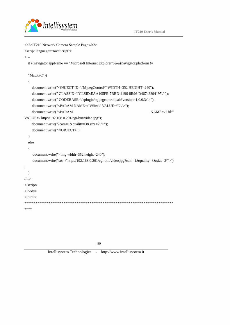
IT210 User’s Manual
Intellisystem Technologies - http://www.intellisystem.it
80
<h2>IT210 Network Camera Sample Page</h2> <script language="JavaScript">
<!--
if ((navigator.appName == "Microsoft Internet Explorer")&&(navigator.platform !=
"MacPPC"))
{
document.write("<OBJECT ID=\"MjpegControl\" WIDTH=352 HEIGHT=240");
document.write(" CLASSID=\"CLSID:EAA105FE-7BBD-4196-8B96-D46743894195\" "); document.write(" CODEBASE=\"/plugin/mjpegcontrol.cab#version=1,0,0,3\">");
document.write("<PARAM NAME=\"VSize\" VALUE=\"2\">");
document.write("<PARAM NAME=\"Url\"
VALUE=\"http://192.168.0.201/cgi-bin/video.jpg"); document.write("?cam=1&quality=3&size=2\">");
document.write("</OBJECT>");
}
else {
document.write("<img width=352 height=240");
document.write("src=\"http://192.168.0.201/cgi-bin/video.jpg?cam=1&quality=3&size=2\">")
; }
//-->
</script>
</body> </html>
********************************************************************************
****
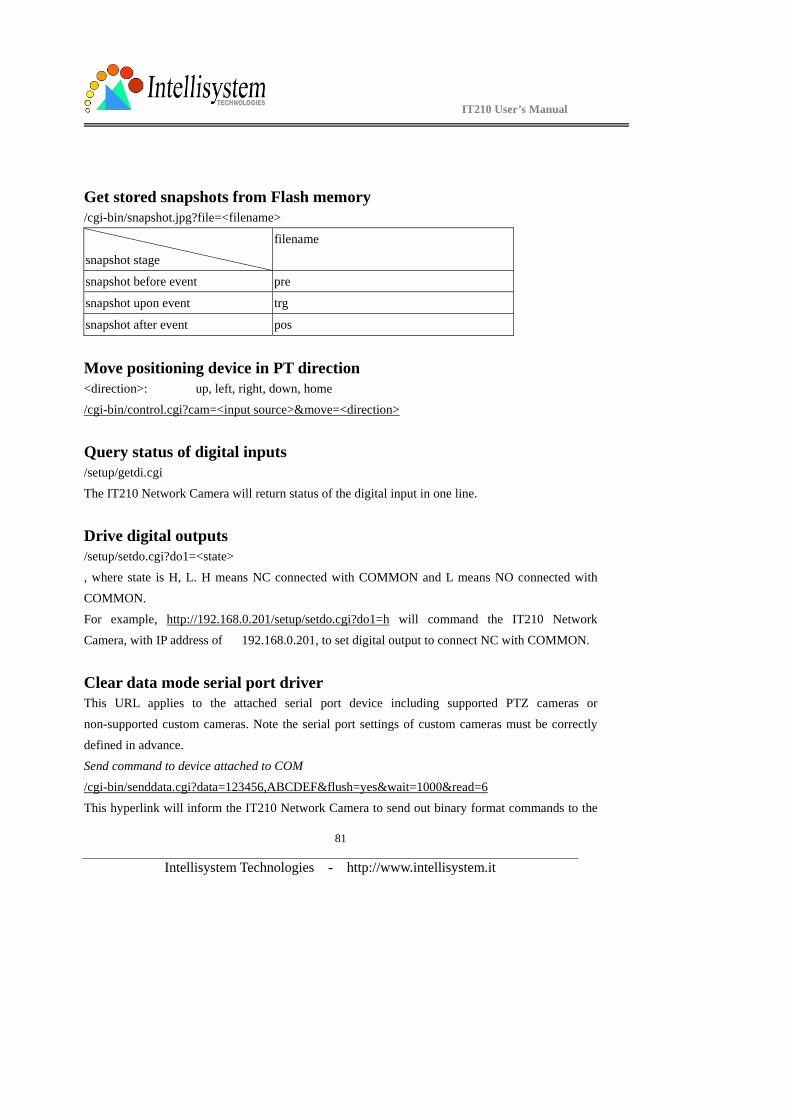
IT210 User’s Manual
Intellisystem Technologies - http://www.intellisystem.it
81
Get stored snapshots from Flash memory /cgi-bin/snapshot.jpg?file=<filename>
snapshot stage
filename
snapshot before event pre
snapshot upon event trg
snapshot after event pos
Move positioning device in PT direction <direction>: up, left, right, down, home
/cgi-bin/control.cgi?cam=<input source>&move=<direction>
Query status of digital inputs /setup/getdi.cgi
The IT210 Network Camera will return status of the digital input in one line.
Drive digital outputs /setup/setdo.cgi?do1=<state>
, where state is H, L. H means NC connected with COMMON and L means NO connected with COMMON.
For example, http://192.168.0.201/setup/setdo.cgi?do1=h will command the IT210 Network
Camera, with IP address of 192.168.0.201, to set digital output to connect NC with COMMON.
Clear data mode serial port driver This URL applies to the attached serial port device including supported PTZ cameras or
non-supported custom cameras. Note the serial port settings of custom cameras must be correctly
defined in advance. Send command to device attached to COM
/cgi-bin/senddata.cgi?data=123456,ABCDEF&flush=yes&wait=1000&read=6
This hyperlink will inform the IT210 Network Camera to send out binary format commands to the
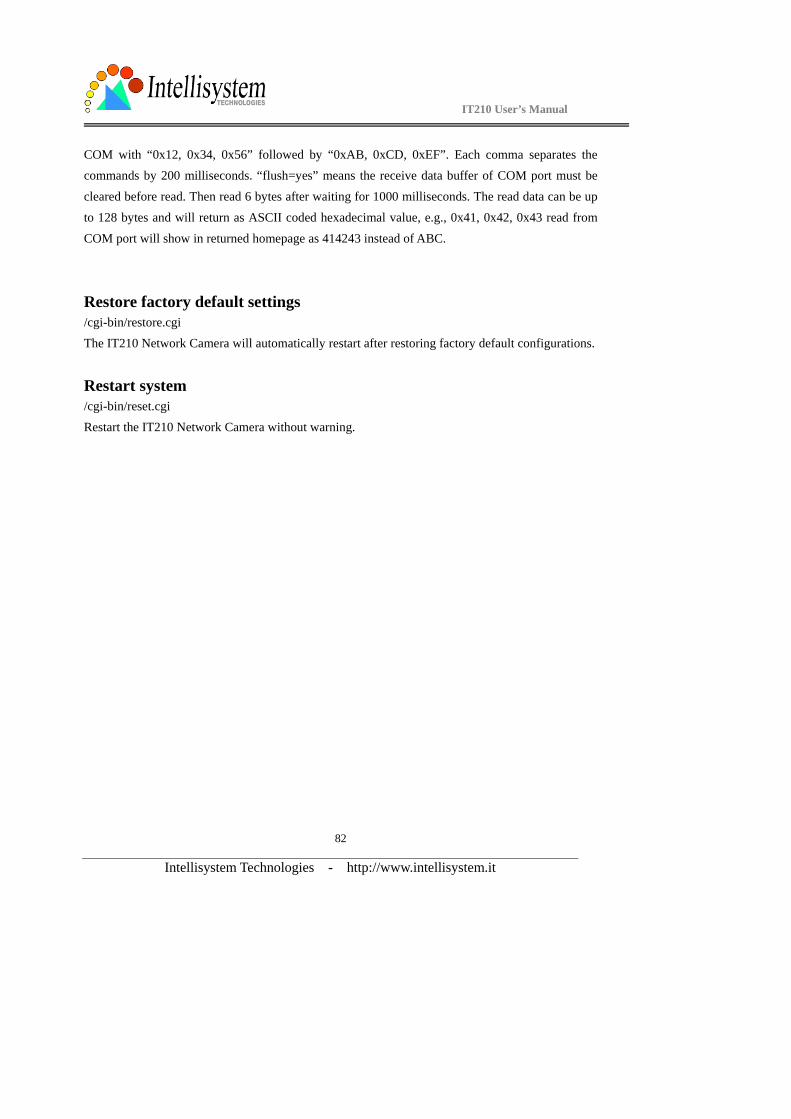
IT210 User’s Manual
Intellisystem Technologies - http://www.intellisystem.it
82
COM with “0x12, 0x34, 0x56” followed by “0xAB, 0xCD, 0xEF”. Each comma separates the commands by 200 milliseconds. “flush=yes” means the receive data buffer of COM port must be
cleared before read. Then read 6 bytes after waiting for 1000 milliseconds. The read data can be up
to 128 bytes and will return as ASCII coded hexadecimal value, e.g., 0x41, 0x42, 0x43 read from
COM port will show in returned homepage as 414243 instead of ABC.
Restore factory default settings /cgi-bin/restore.cgi The IT210 Network Camera will automatically restart after restoring factory default configurations.
Restart system /cgi-bin/reset.cgi Restart the IT210 Network Camera without warning.
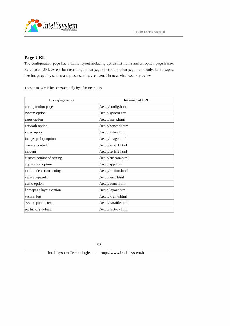
IT210 User’s Manual
Intellisystem Technologies - http://www.intellisystem.it
83
Page URL The configuration page has a frame layout including option list frame and an option page frame.
Referenced URL except for the configuration page directs to option page frame only. Some pages, like image quality setting and preset setting, are opened in new windows for preview.
These URLs can be accessed only by administrators.
Homepage name Referenced URL
configuration page /setup/config.html
system option /setup/system.html
users option /setup/users.html
network option /setup/network.html
video option /setup/video.html
image quality option /setup/image.html
camera control /setup/serial1.html
modem /setup/serial2.html
custom command setting /setup/cuscom.html
application option /setup/app.html
motion detection setting /setup/motion.html
view snapshots /setup/snap.html
demo option /setup/demo.html
homepage layout option /setup/layout.html
system log /setup/logfile.html
system parameters /setup/parafile.html
set factory default /setup/factory.html
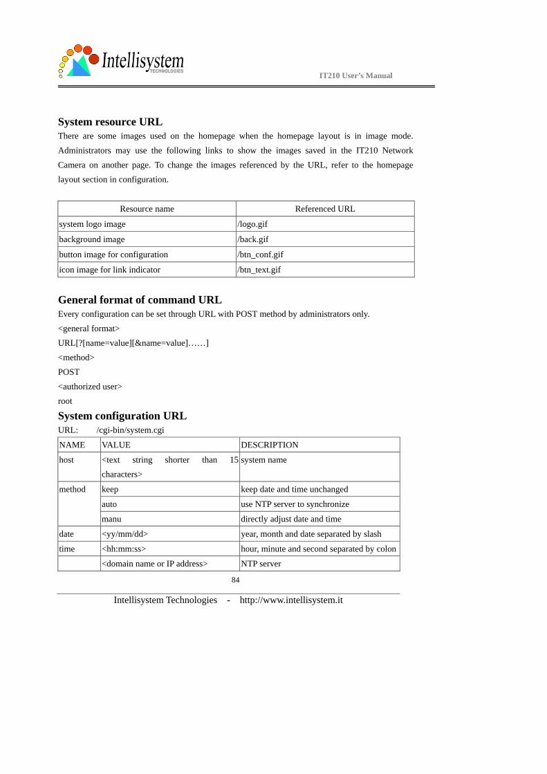
IT210 User’s Manual
Intellisystem Technologies - http://www.intellisystem.it
84
System resource URL There are some images used on the homepage when the homepage layout is in image mode.
Administrators may use the following links to show the images saved in the IT210 Network
Camera on another page. To change the images referenced by the URL, refer to the homepage layout section in configuration.
Resource name Referenced URL
system logo image /logo.gif
background image /back.gif
button image for configuration /btn_conf.gif
icon image for link indicator /btn_text.gif
General format of command URL Every configuration can be set through URL with POST method by administrators only.
<general format> URL[?[name=value][&name=value]……]
<method>
POST
<authorized user> root
System configuration URL URL: /cgi-bin/system.cgi
NAME VALUE DESCRIPTION
host <text string shorter than 15
characters>
system name
keep keep date and time unchanged
auto use NTP server to synchronize
method
manu directly adjust date and time
date <yy/mm/dd> year, month and date separated by slash
time <hh:mm:ss> hour, minute and second separated by colon
<domain name or IP address> NTP server
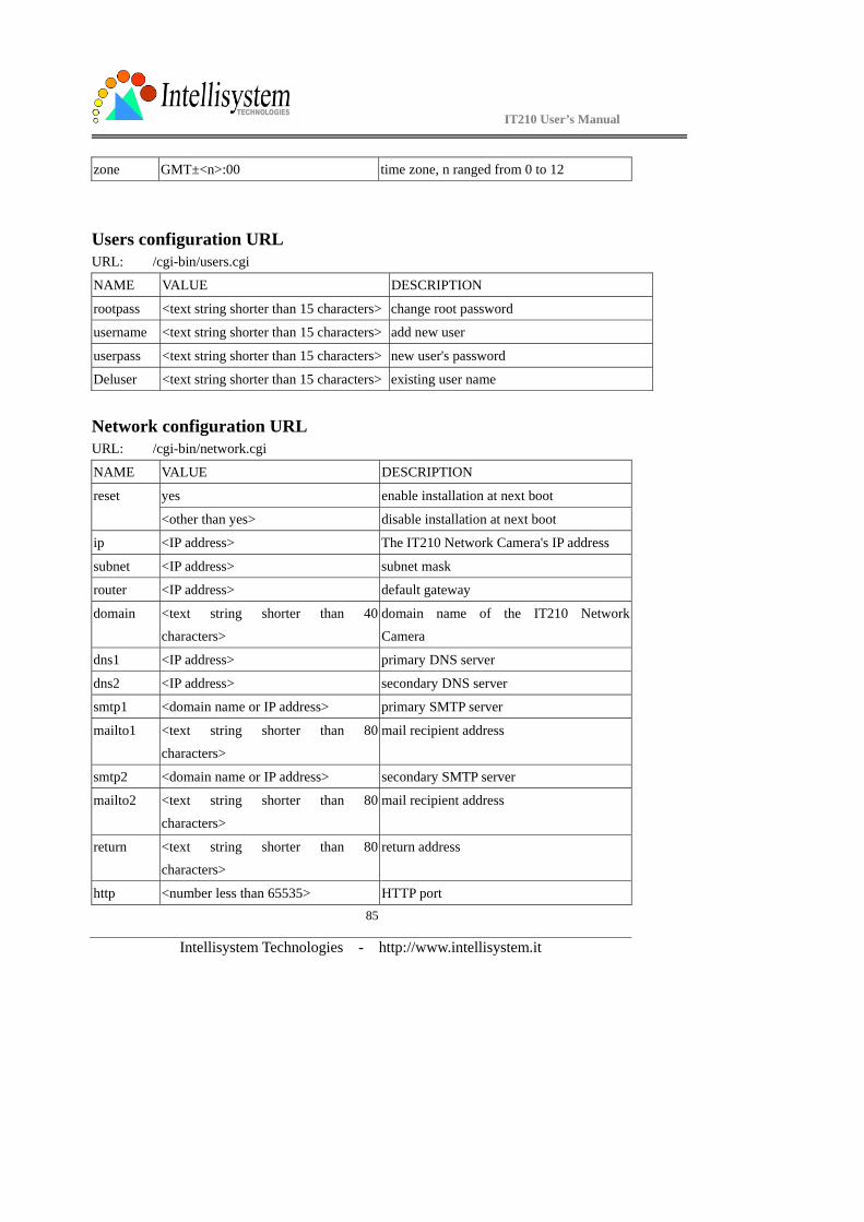
IT210 User’s Manual
Intellisystem Technologies - http://www.intellisystem.it
85
zone GMT±<n>:00 time zone, n ranged from 0 to 12
Users configuration URL URL: /cgi-bin/users.cgi
NAME VALUE DESCRIPTION
rootpass <text string shorter than 15 characters> change root password
username <text string shorter than 15 characters> add new user
userpass <text string shorter than 15 characters> new user's password
Deluser <text string shorter than 15 characters> existing user name
Network configuration URL URL: /cgi-bin/network.cgi
NAME VALUE DESCRIPTION
yes enable installation at next boot reset
<other than yes> disable installation at next boot
ip <IP address> The IT210 Network Camera's IP address
subnet <IP address> subnet mask
router <IP address> default gateway
domain <text string shorter than 40 characters>
domain name of the IT210 Network Camera
dns1 <IP address> primary DNS server
dns2 <IP address> secondary DNS server
smtp1 <domain name or IP address> primary SMTP server
mailto1 <text string shorter than 80
characters>
mail recipient address
smtp2 <domain name or IP address> secondary SMTP server
mailto2 <text string shorter than 80
characters>
mail recipient address
return <text string shorter than 80 characters>
return address
http <number less than 65535> HTTP port
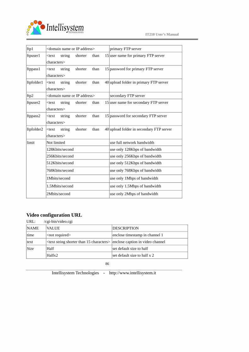
IT210 User’s Manual
Intellisystem Technologies - http://www.intellisystem.it
86
ftp1 <domain name or IP address> primary FTP server
ftpuser1 <text string shorter than 15
characters>
user name for primary FTP server
ftppass1 <text string shorter than 15
characters>
password for primary FTP server
ftpfolder1 <text string shorter than 40
characters>
upload folder in primary FTP server
ftp2 <domain name or IP address> secondary FTP server
ftpuser2 <text string shorter than 15 characters>
user name for secondary FTP server
ftppass2 <text string shorter than 15
characters>
password for secondary FTP server
ftpfolder2 <text string shorter than 40
characters>
upload folder in secondary FTP server
Not limited use full network bandwidth
128Kbits/second use only 128Kbps of bandwidth
256Kbits/second use only 256Kbps of bandwidth
512Kbits/second use only 512Kbps of bandwidth
768Kbits/second use only 768Kbps of bandwidth
1Mbits/second use only 1Mbps of bandwidth
1.5Mbits/second use only 1.5Mbps of bandwidth
limit
2Mbits/second use only 2Mbps of bandwidth
Video configuration URL URL: /cgi-bin/video.cgi
NAME VALUE DESCRIPTION
time <not required> enclose timestamp in channel 1
text <text string shorter than 15 characters> enclose caption in video channel
Half set default size to half Size
Halfx2 set default size to half x 2

IT210 User’s Manual
Intellisystem Technologies - http://www.intellisystem.it
87
Standard set default size to standard
Standardx2 set default size to standard x 2
Double set default size to double
Medium lowest resolution of video
Standard lower resolution of video
Good normal setting of video
Detailed higher resolution of video
quality
Excellent highest resolution of video
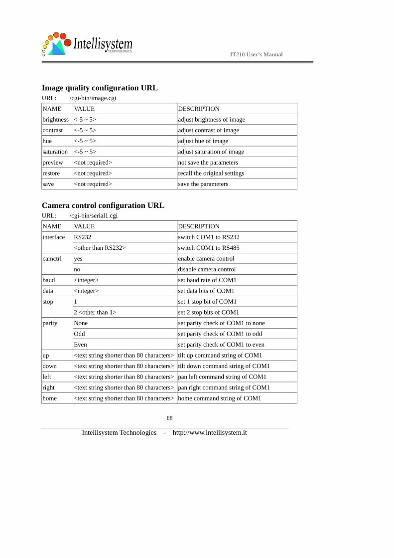
IT210 User’s Manual
Intellisystem Technologies - http://www.intellisystem.it
88
Image quality configuration URL URL: /cgi-bin/image.cgi
NAME VALUE DESCRIPTION
brightness <-5 ~ 5> adjust brightness of image
contrast <-5 ~ 5> adjust contrast of image
hue <-5 ~ 5> adjust hue of image
saturation <-5 ~ 5> adjust saturation of image
preview <not required> not save the parameters
restore <not required> recall the original settings
save <not required> save the parameters
Camera control configuration URL URL: /cgi-bin/serial1.cgi
NAME VALUE DESCRIPTION
RS232 switch COM1 to RS232 interface
<other than RS232> switch COM1 to RS485
yes enable camera control camctrl
no disable camera control
baud <integer> set baud rate of COM1
data <integer> set data bits of COM1
1 set 1 stop bit of COM1 stop
2 <other than 1> set 2 stop bits of COM1
None set parity check of COM1 to none
Odd set parity check of COM1 to odd
parity
Even set parity check of COM1 to even
up <text string shorter than 80 characters> tilt up command string of COM1
down <text string shorter than 80 characters> tilt down command string of COM1
left <text string shorter than 80 characters> pan left command string of COM1
right <text string shorter than 80 characters> pan right command string of COM1
home <text string shorter than 80 characters> home command string of COM1
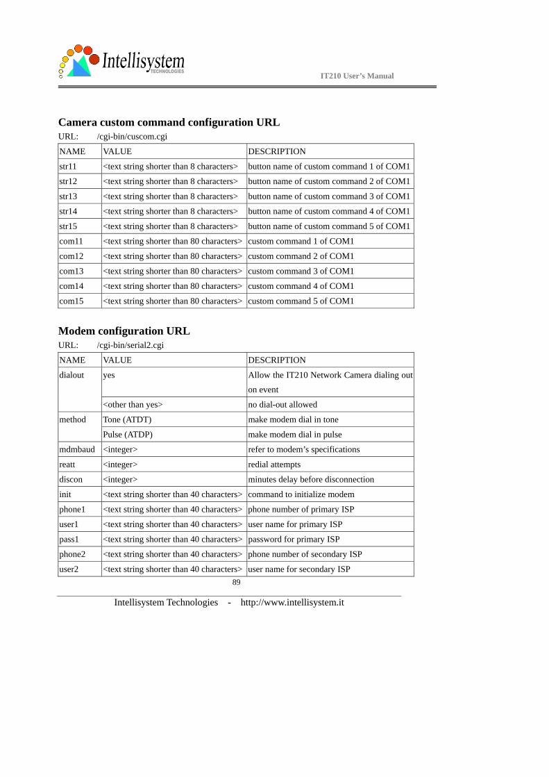
IT210 User’s Manual
Intellisystem Technologies - http://www.intellisystem.it
89
Camera custom command configuration URL URL: /cgi-bin/cuscom.cgi
NAME VALUE DESCRIPTION
str11 <text string shorter than 8 characters> button name of custom command 1 of COM1
str12 <text string shorter than 8 characters> button name of custom command 2 of COM1
str13 <text string shorter than 8 characters> button name of custom command 3 of COM1
str14 <text string shorter than 8 characters> button name of custom command 4 of COM1
str15 <text string shorter than 8 characters> button name of custom command 5 of COM1
com11 <text string shorter than 80 characters> custom command 1 of COM1
com12 <text string shorter than 80 characters> custom command 2 of COM1
com13 <text string shorter than 80 characters> custom command 3 of COM1
com14 <text string shorter than 80 characters> custom command 4 of COM1
com15 <text string shorter than 80 characters> custom command 5 of COM1
Modem configuration URL URL: /cgi-bin/serial2.cgi
NAME VALUE DESCRIPTION
yes Allow the IT210 Network Camera dialing out
on event
dialout
<other than yes> no dial-out allowed
Tone (ATDT) make modem dial in tone method
Pulse (ATDP) make modem dial in pulse
mdmbaud <integer> refer to modem’s specifications
reatt <integer> redial attempts
discon <integer> minutes delay before disconnection
init <text string shorter than 40 characters> command to initialize modem
phone1 <text string shorter than 40 characters> phone number of primary ISP
user1 <text string shorter than 40 characters> user name for primary ISP
pass1 <text string shorter than 40 characters> password for primary ISP
phone2 <text string shorter than 40 characters> phone number of secondary ISP
user2 <text string shorter than 40 characters> user name for secondary ISP
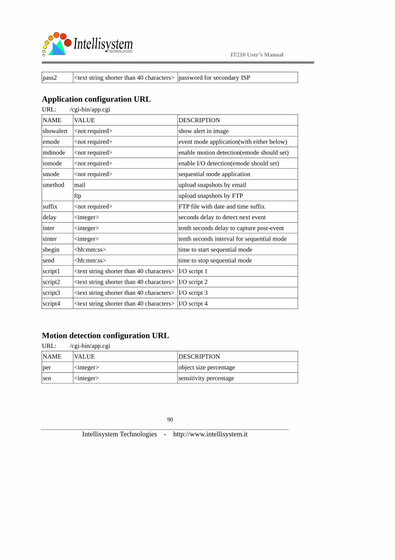
IT210 User’s Manual
Intellisystem Technologies - http://www.intellisystem.it
90
pass2 <text string shorter than 40 characters> password for secondary ISP
Application configuration URL URL: /cgi-bin/app.cgi
NAME VALUE DESCRIPTION
showalert <not required> show alert in image
emode <not required> event mode application(with either below)
mdmode <not required> enable motion detection(emode should set)
iomode <not required> enable I/O detection(emode should set)
smode <not required> sequential mode application
mail upload snapshots by email smethod
ftp upload snapshots by FTP
suffix <not required> FTP file with date and time suffix
delay <integer> seconds delay to detect next event
inter <integer> tenth seconds delay to capture post-event
sinter <integer> tenth seconds interval for sequential mode
sbegin <hh:mm:ss> time to start sequential mode
send <hh:mm:ss> time to stop sequential mode
script1 <text string shorter than 40 characters> I/O script 1
script2 <text string shorter than 40 characters> I/O script 2
script3 <text string shorter than 40 characters> I/O script 3
script4 <text string shorter than 40 characters> I/O script 4
Motion detection configuration URL URL: /cgi-bin/app.cgi
NAME VALUE DESCRIPTION
per <integer> object size percentage
sen <integer> sensitivity percentage
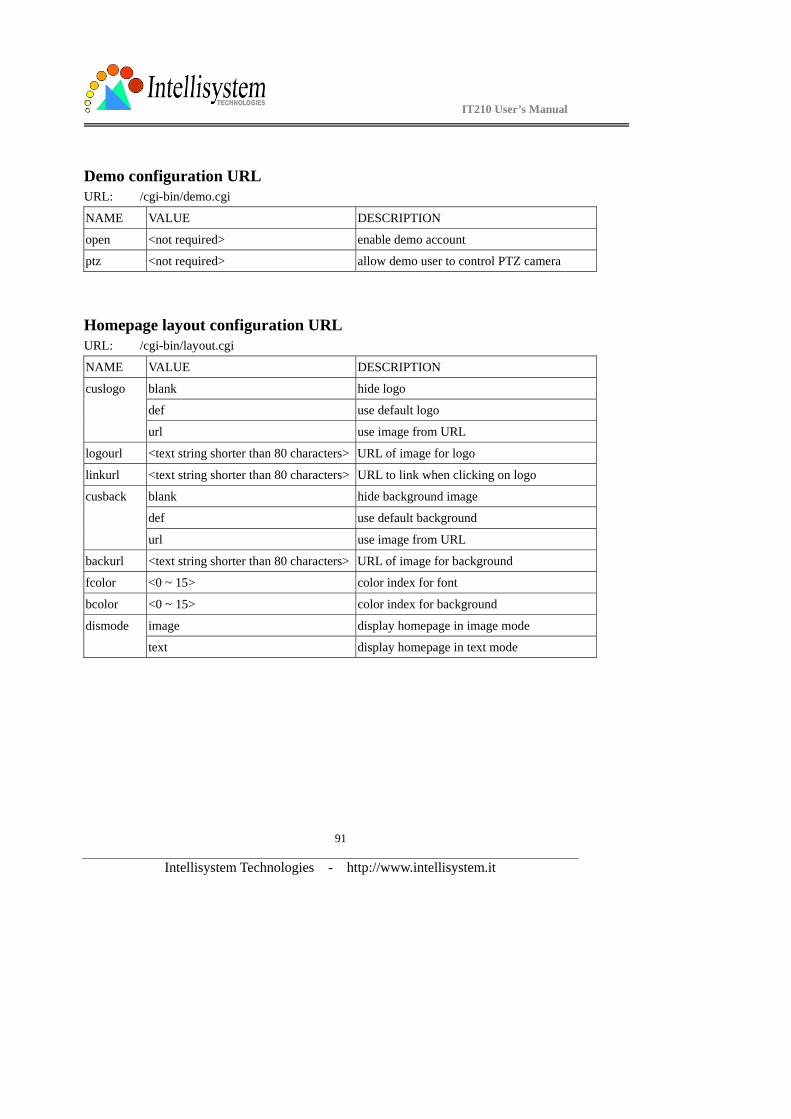
IT210 User’s Manual
Intellisystem Technologies - http://www.intellisystem.it
91
Demo configuration URL URL: /cgi-bin/demo.cgi
NAME VALUE DESCRIPTION
open <not required> enable demo account
ptz <not required> allow demo user to control PTZ camera
Homepage layout configuration URL URL: /cgi-bin/layout.cgi
NAME VALUE DESCRIPTION
blank hide logo
def use default logo
cuslogo
url use image from URL
logourl <text string shorter than 80 characters> URL of image for logo
linkurl <text string shorter than 80 characters> URL to link when clicking on logo
blank hide background image
def use default background
cusback
url use image from URL
backurl <text string shorter than 80 characters> URL of image for background
fcolor <0 ~ 15> color index for font
bcolor <0 ~ 15> color index for background
image display homepage in image mode dismode
text display homepage in text mode
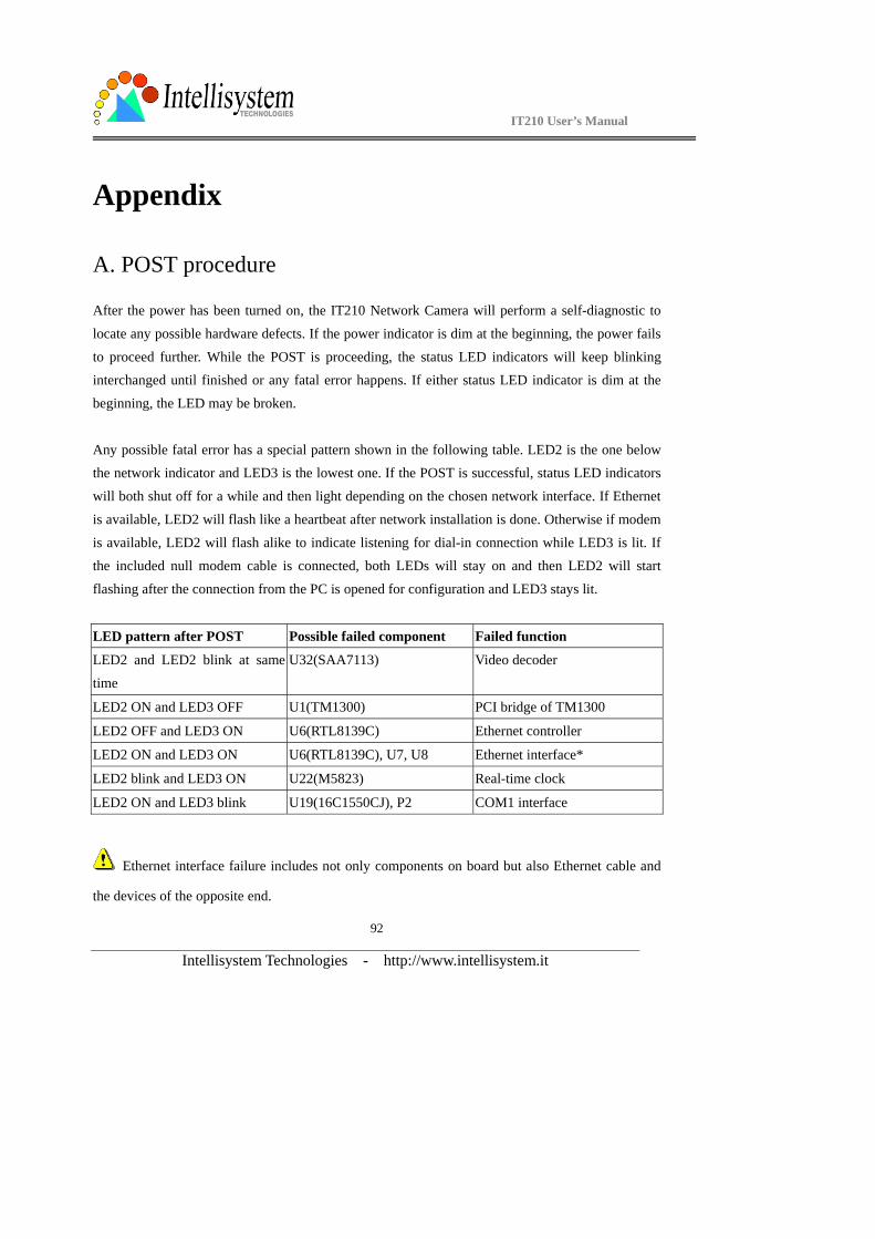
IT210 User’s Manual
Intellisystem Technologies - http://www.intellisystem.it
92
Appendix
A. POST procedure
After the power has been turned on, the IT210 Network Camera will perform a self-diagnostic to
locate any possible hardware defects. If the power indicator is dim at the beginning, the power fails
to proceed further. While the POST is proceeding, the status LED indicators will keep blinking interchanged until finished or any fatal error happens. If either status LED indicator is dim at the
beginning, the LED may be broken.
Any possible fatal error has a special pattern shown in the following table. LED2 is the one below the network indicator and LED3 is the lowest one. If the POST is successful, status LED indicators
will both shut off for a while and then light depending on the chosen network interface. If Ethernet
is available, LED2 will flash like a heartbeat after network installation is done. Otherwise if modem
is available, LED2 will flash alike to indicate listening for dial-in connection while LED3 is lit. If the included null modem cable is connected, both LEDs will stay on and then LED2 will start
flashing after the connection from the PC is opened for configuration and LED3 stays lit.
LED pattern after POST Possible failed component Failed function
LED2 and LED2 blink at same
time
U32(SAA7113) Video decoder
LED2 ON and LED3 OFF U1(TM1300) PCI bridge of TM1300
LED2 OFF and LED3 ON U6(RTL8139C) Ethernet controller
LED2 ON and LED3 ON U6(RTL8139C), U7, U8 Ethernet interface*
LED2 blink and LED3 ON U22(M5823) Real-time clock
LED2 ON and LED3 blink U19(16C1550CJ), P2 COM1 interface
Ethernet interface failure includes not only components on board but also Ethernet cable and
the devices of the opposite end.
IT210 User’s Manual
Intellisystem Technologies - http://www.intellisystem.it
93
B. Frequently asked questions
Q. What if I forget my password?
A. Every access to the IT210 Network Camera needs authentication. If you are not a permitted user, you may view the images or control the camera as long as the demo account is opened. The demo
account user may use username as “demo” without any password to access limited features. If you
are one of the managed users, you have to ask the administrators for the password. If you are the
administrator, there is no way to recover the root password. The only way to regain access to the IT210 Network Camera is to utilize the clear button on the front panel to restore the factory settings
and reinstall it.
Q. Why can I not watch video from the IT210 Network Camera after it is authenticated? A. There are many possible scenarios regarding this problem,
1.If you have just installed the IT210 Network Camera and are unable to watch the video, check if
the video input is enabled and the video modulation in Configuration page.
2.If the IT210 Network Camera is well installed and you are accessing the IT210 Network Camera for the first time using Internet Explorer, adjust the security level of Internet Explorer to allow
installation of the plug-in.
3.If the problem still exists after adjusting, the current users may be over the system allows.
4.In case that you use demo account, the video may be protected from the public by the administrator.
Q. What is the plug-in for?
A. The plug-in provided by the IT210 Network Camera is used to display motion pictures on Internet Explorer. If your system does not allow installation of any plug-in software, the security
level of web browser may need to be lowered. It is recommended that you consult your network
supervisor in your office regarding the adjustment of the security level.
Q. Why is the timestamp different from the system time of my PC or notebook?
A. The timestamp is based on the system time of the IT210 Network Camera. It is maintained by a
real-time clock inside and automatically synchronizes with the time server if the IT210 Network
IT210 User’s Manual
Intellisystem Technologies - http://www.intellisystem.it
94
Camera is connected to the Internet and the function is enabled. Differences of several hours may result from the time zone setting.
Q. Why does the image not refresh regularly?
A. In a modem environment, it is because the bandwidth of PPP connection is far less than Ethernet. If the difference of the timestamp is not stable, adjust the UART FIFO lower in both receiving and
transmitting from modem property in the control panel. While in Ethernet, it may be due to
insufficient network bandwidth shared by other users.
Q. How does the IT210 Network Camera detect the supported PTZ cameras automatically?
A. When the system is powered up, the IT210 Network Camera will monitor the CTS of camera
control cable continuously. As long as the CTS is detected, the IT210 Network Camera will try to
handshake with supported cameras until a supported camera is found. There is no more camera detection once a PTZ camera is recognized.
Q. How many users are allowed to watch the IT210 Network Camera at the same time?
A. To achieve the best effect, the IT210 Network Camera will allow twenty users to connect at the same time. It is recommended to build another web server to host a large quantity of users by
retrieving images from the IT210 Network Camera periodically.
Q. How fast is the video rate of the IT210 Network Camera? A. The JPEG codec can process 30 frames per second internally. However the total performance is
subject to many coefficients as follows,
1. network throughput and bandwidth share,
2. number of users, 3. the complicated objects in view results in larger image file,
4. the level of your PC or notebook which is responsible of displaying images.
In general, the transfer rate in general local network environment can achieve over 200 kilobytes
per second and approximately 10 to 20 pictures of normal environment per second.
Q. How can I keep the IT210 Network Camera as private as possible?
A. The IT210 Network Camera is designed for surveillance purpose and has many flexible
Formattati: Elenchi puntati enumerati
IT210 User’s Manual
Intellisystem Technologies - http://www.intellisystem.it
95
interfaces. The user authentication and special confirmation in installation can keep the IT210 Network Camera from unauthorized access. You may also change the HTTP port to non-public
number. You can check system log to examine any abnormal activities and trace the origins.
Q. How fast will the IT210 Network Camera check the status of digital inputs?
A. The IT210 Network Camera will check input status in less than half a second. However, to avoid
repeatedly checking conditions too often and to allow the devices connected to digital outputs to
function properly, the IT210 Network Camera will delay 3 seconds by default after each condition
matches. Users may change it according to specific applications. During this period, any condition will be ignored.
Q. If I set the IT210 Network Camera to send e-mails of images whenever the conditions are met,
will my e-mail account overflow? A. It is recommended to use transient state rather than steady state. For instance, use ‘/’ and ‘\’
instead of ‘H’ and ‘L’ to let the condition be triggered only when state is changed.
Q. Why can I not access the IT210 Network Camera when I setup some options in the application? A. When the IT210 Network Camera is triggered by events, snapshots will take more time to write
them into memory and take further action like email or FTP. If the events occur too often, the
system will always be busy with sending images. That will make users feel like the system
responding too slowly. If it is in sequential mode, the uploading speed depends on the network utilization, server performance and how many users are accessing the video. Once the system is too
busy to configure, use the restore factory default and reset button to save the system.
IT210 User’s Manual
Intellisystem Technologies - http://www.intellisystem.it
96
C. Technical specifications
Remote Management Configuration and system log can be accessed via Web browser and FTP application remotely. Networking Protocol TCP/IP, HTTP, SMTP, FTP, Telnet, NTP, DNS and DHCP Modem PPP(dial-up, direct cable connection) Physical 10baseT Ethernet or 100baseT Fast Ethernet Video Algorithm Supported MJPEG Features Adjustable image size and quality Time stamp and text overlay Resolution NTSC(IT210) Up to 30 frames at 176x120 Up to 30 frames at 352X240 Up to 10 frames at 704X480 PAL(IT210) Up to 25 frames at 176x144 Up to 25 frames at 352X288 Up to 10 frames at 704X576 Camera Specification 1/3 inch color CCD 512(H) x 492(V)(NTSC) / 512(H) x 582(V)(PAL) 1 Lux / F2.0 AGC, AWB, AI/AES Electronic shutter: 1/60 (1/50) to 1/100,000 sec. Standard C or CS mount lens fitting General I/O 1 opto-isolated sensor inputs (max. 12VDC 50mA) 1 output relays (max. 24VDC 1A, 125VAC 0.5A)
Alarm FeaturesMotion detection with percentage and sensitivity Daily repeat timing schedule 3 color images per camera for pre/post alarm image storage Automatic transfer of stored images via email or FTP with event- triggered actions RS232/RS485 9 pin D-SUB RS232 or RS485 max.115.2Kbps PAN/TILT PT positioning device control through RS232 or RS485 Clear-data command driver is supported Remote Software Upgrade System firmware upgradeable via FTP Security Administrator and user group protected 15 digits password protection Demo account with limitation by administrator Optional Software Record and play pictures on PC hard disk I/O ports monitoring feature LED Indicator Heartbeat indicator Status indicators Network indicator Power 12V DC, 1.2A external power supply Viewing System Requirement Protocol Standard internet TCP/IP suite Operating System Microsoft Windows, Linux, Unix and Mac OS Browser Internet Explorer 4.x or above, Netscape Navigator 4.x or above
IT210 User’s Manual
Intellisystem Technologies - http://www.intellisystem.it
97
Electromagnetic Compatibility (EMC) USA - This equipment has been tested and found to comply with the limits for a Class B digital device,
pursuant to Part 15 of the FCC Rules. These limits are designed to provide reasonable protection against
harmful interference in a residential installation. This equipment generates, uses and can radiate radio
frequency energy and, if not installed and used in accordance with the instructions, may cause harmful
interference to radio communications. However, there is no guarantee that interference will not occur in a
partial installation. If this equipment does cause harmful interference to radio or television reception, which can
be determined by turning the equipment off and on, the user is encouraged to try to correct the interference by
one or more of the following measures:
-- Reorient or relocate the receiving antenna.
-- Increase the seperation between the equipment and receiver.
-- Connect the equipment into an outlet on a circuit different from that to which the receiver is
connected.
-- Consult the dealer or an experienced radio/TV technician for help.
Shielded interface cables must be used in order to comply with emission limits.
Europe - This digital equipment fulfills the requirement for radiated emission according to
limit B of EN55022/1998, and the requirement for immunity according to EN50082-1/1992.
Liability Intellisystem Technologies S.r.l. cannot be held responsible for any technical or typographical errors and
reserves the right to make changes to the product and manuals without prior notice. Intellisystem Technologies
S.r.l. makes no warranty of any kind with regard to the material contained within this document, including, but
IT210 User’s Manual
Intellisystem Technologies - http://www.intellisystem.it
98
not limited to, the implied warranties of merchantability and fitness for a particular purpose. All other company
names and products are trademark or registered trademarks of their respective companies.
For any question and support please contact:
Intellisystem Technologies S.r.l.
Support: [email protected] Web Site: http://www.intellisystem.it

IT210 User’s Manual
Intellisystem Technologies - http://www.intellisystem.it
99
Notes :