user guide - andymarkfiles.andymark.com/pdfs/am14u2_userguide2015_rev3.pdf · • output shaft:...
TRANSCRIPT

User Guide AM14U2 Drive System for the
2015 FIRST Robotics Competition

AndyMark – Your Robot Parts Experts AndyMark, Inc. was founded in 2004 by Andy Baker and Mark Koors to design and sell unique mechanical parts for competition and educational robotics. Through their volunteer work with FIRST Robotics Competitions, they identified a niche market and began designing and selling robotics components for FIRST teams. At that time, many designs were being shared and re-created, but finding the correct fabrication resources for these parts was difficult for some FRC teams. AndyMark has been a proud supplier of the FRC program since 2005.
System Overview The 2015 AM14U2 Drive System is designed for use in the 2015 FIRST Robotics Competition (FRC). The AM14U2 Drive System includes standard AndyMark products and are designed to also work with additional AndyMark products.
Additional Instructions Available We encourage customers to seek product information at www.andymark.com, contact us via e-mail at [email protected], or call Toll-Free 877-868-4770 with questions about any of our products.
Best of luck to all the FIRST Teams in the 2015 FRC season!
Detailed assembly tips and instruction videos can be found on the AndyMark YouTube channel. Additional resources, drawings, and CAD are available on the “http://www.andymark.com/KOP” web page.
AM14U2 Recommended Hand Tool List (not included) Component Part Number QTY Part Photo Hammer available at your
local hardware store 1
3/8" Magnetic Nut Setter am-2755 1
5/16" Magnetic Nut Setter am-2754 1
9/16" Socket, 3/8" Drive am-2743 1
3/8" Socket, 3/8" Drive am-2740 1
5/32" Ball End Hex Driver am-2751 1
3/8" Drive Quick Release Ratchet am-2753 1
1/2" - 9/16" Open-End Wrench am-2746 1
2
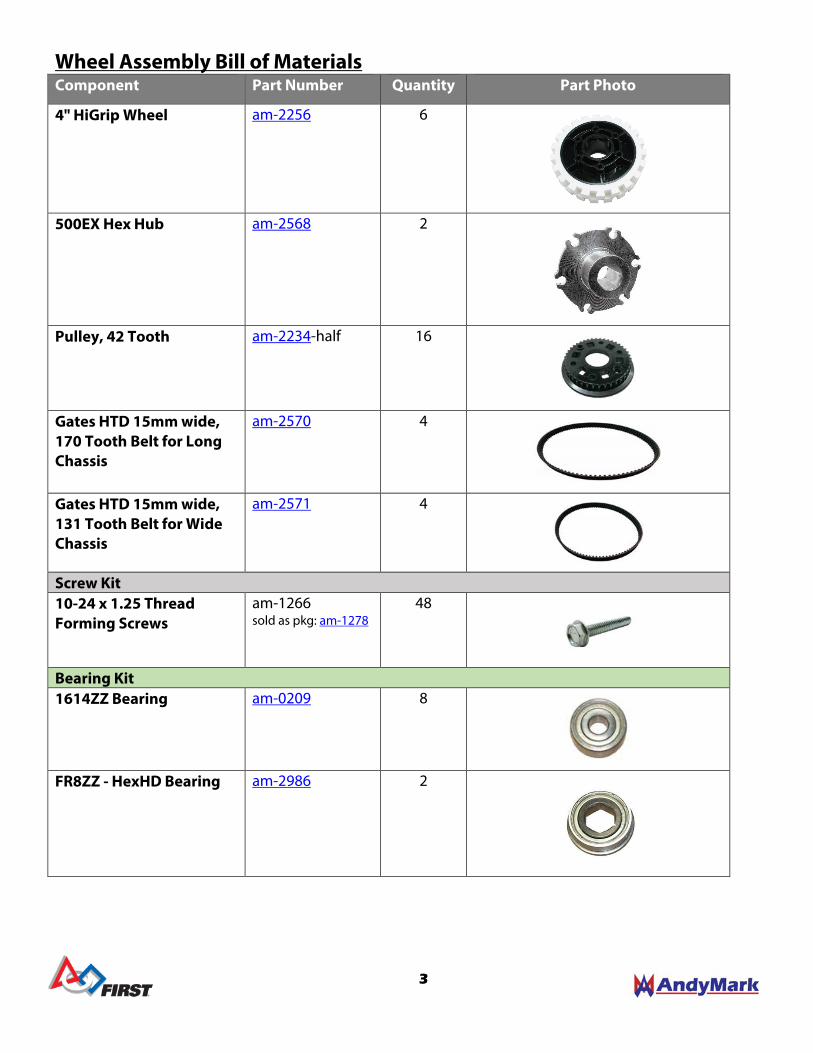
Wheel Assembly Bill of Materials Component Part Number Quantity Part Photo
4" HiGrip Wheel am-2256 6
500EX Hex Hub am-2568 2
Pulley, 42 Tooth am-2234-half 16
Gates HTD 15mm wide, 170 Tooth Belt for Long Chassis
am-2570 4
Gates HTD 15mm wide, 131 Tooth Belt for Wide Chassis
am-2571 4
Screw Kit 10-24 x 1.25 Thread Forming Screws
am-1266 sold as pkg: am-1278
48
Bearing Kit 1614ZZ Bearing am-0209 8
FR8ZZ - HexHD Bearing am-2986 2
3

Toughbox Mini Overview
Each KOP chassis includes two (2) AndyMark Toughbox Mini Gearboxes (am-2598) unassembled. Each Toughbox Mini includes the parts needed to mount two 2.5” CIM motors. Each gearbox has mounting holes for optional encoders. Gearbox Specifications:
• Gear Profile: 20 dp, 14.5 degree pressure angle • Gear Material: Cold-formed 4140 Steel • Gear Ratio: 8.45:1
o CIM Gear: 14 Tooth (8mm bore w/ 2mm keyway) o Large Cluster Gear: 50 Tooth (3/8” Hex bore) o Small Cluster Gear: 19 Tooth (3/8” Hex bore)* o Large Output Gear: 45 Tooth (½”Hex bore)*
• Output Shaft: ½” Hex, 4140 Steel • Housing Material: Nylon 6/6 with long fiber reinforcements
*To change the speed of the AM14U2, different gear ratios can be used in the Toughbox Mini. The AM14U2 features a center wheel directly driven by a TB Mini Hex Output Shaft. To change the ratio and drive speed, the standard 19 tooth Small Cluster Gear and 45 tooth Large Output Gear will need to be replaced with two gears totaling 64 teeth. More information about these optional gears can be found at "AndyMark.com/TBmini".
Ratio CIM Gear Lg. Cluster Sm. Cluster Lg. Output AM14U2 Speed** 5.95:1 14T (am-0034) 50T (am-0149) 24T (am-0177) 40T (am-0178) 12.1 ft/sec 7.31:1 14T (am-0034) 50T (am-0149) 21T (am-2564) 43T (am-2565) 9.8 ft/sec 8.46:1 (Included) 14T (am-0034) 50T (am-0149) 19T (am-0176) 45T (am-0179) 8.5 ft/sec 10.71:1 14T (am-0034) 50T (am-0149) 16T (am-0747) 48T (am-0885) 6.7 ft/sec 12.75:1 14T (am-0034) 50T (am-0149) 14T (am-0151) 50T (am-0150) 5.6 ft/sec
**AM14U2 speed estimation is based on calculations using 4” wheels, and one CIM motor per TB Mini running at 4100 rpm, or 75% of free speed.
Toughbox Mini Bill of Materials Component Part Number Quantity Part Photo TB Mini Housing am-0650 1
TB Mini Hex Output Shaft am-2566 1
TB Mini Small Hex Shaft am-0152 1
4

TB Mini Kit 1 – Gears - Yellow 50 Tooth, 3/8 Hex Gear am-0149 1
14 Tooth, 8mm CIM Gear am-0034 2
19 Tooth, 3/8” Hex Gear am-0176 1
45 Tooth, ½” Hex Gear am-0179 1
TB Mini Kit 2 – Bearings - Purple R6ZZ Bearing am-0516 2
FR6ZZ Bearing am-0028 1
FR8ZZ HexHD Bearing am-2986 1
TB Mini Kit 3 – CIM Hardware - Red 2x2x10mm Machine Key am-1121 2
5/16" Washer am-1009 sold as pkg: am-1219
4
8mm Retaining Clip am-0033 2
10-32 x 0.625” SHCS with Yellow Patch
am-1120 sold as pkg: am-1246
4
TB Mini Kit 4 – TB Hardware - Blue 10-32 x 0.75” SHCS am-1047
sold as pkg: am-1280 4
10-32 Nylock Nut am-1042
sold as pkg: am-1211 4
Grease Pack am-2768 1
1/2" E-Clip Ring am-0206 1
5

AM14U2 Chassis Frame Bill of Materials Component Part Number QTY Part Photo AM14U2 Outer Plate am-2951 2
AM14U2 Inner Plate am-2952 2
AM14U2 End Plate am-2953 2
2x3 Hole Bracket am-2954 4
500 Churro, 24.25" am-2974 2
500 Churro, 3.375" am-2569 8
Chassis Kit 1 – Support Screws – Light Blue 1/4-20 x ¾” Thread Rolling Screw
am-1310 sold as pkg: am-1321
20
Chassis Kit 2 – Axle Bolts - Orange 3/8-16 x 4.25” HHS Bolt
am-1297 4
3/8-16 Nylock Nut am-1054 4
Chassis Kit 3 – Wheel Spacers - Green 0.570" Hex Spacer am-1305 2
Plastic Spacer 0.280" am-1306 4
Plastic Spacer 0.850" am-1307 4
Chassis Kit 4 – 10-32 Hardware A - Grey
10-32 x 0.5” SHCS am-1002 sold as pkg: am-1178
32
10-32 Nylock Nut am-1042 sold as pkg: am-1211
32
Chassis Kit 5 – 10-32 Hardware B - Aqua 10-32 x 0.5 SHCS am-1002
sold as pkg: am-1178 8
10-32 Nylock Nut am-1042
sold as pkg: am-1211 8
6

Frame Diagrams & Cut Lines: The AM14U2 is designed for multiple configurations. Chassis pieces should be measured and cut down to size, some possible configurations are shown below. Ensure that your final frame size complies with all 2015 FRC rules. Belts for LONG and WIDE configurations ONLY are included in this kit. Belts for SQUARE can be purchased separately.
151T Belts (am-2706) for this chassis are sold separately.
7
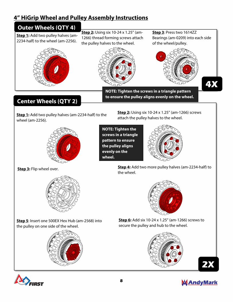
4” HiGrip Wheel and Pulley Assembly Instructions
Outer Wheels (QTY 4) Step 1: Add two pulley halves (am-2234-half) to the wheel (am-2256).
Step 2: Using six 10-24 x 1.25” (am-1266) thread forming screws attach the pulley halves to the wheel.
Step 3: Press two 1614ZZ Bearings (am-0209) into each side of the wheel/pulley.
4X
Center Wheels (QTY 2)
Step 2: Using six 10-24 x 1.25” (am-1266) screws attach the pulley halves to the wheel.
Step 4: Add two more pulley halves (am-2234-half) to the wheel.
Step 3: Flip wheel over.
Step 5: Insert one 500EX Hex Hub (am-2568) into the pulley on one side of the wheel.
Step 6: Add six 10-24 x 1.25” (am-1266) screws to secure the pulley and hub to the wheel.
Step 1: Add two pulley halves (am-2234-half) to the wheel (am-2256).
2X
NOTE: Tighten the screws in a triangle pattern to ensure the pulley aligns evenly on the wheel.
NOTE: Tighten the screws in a triangle pattern to ensure the pulley aligns evenly on the wheel.
8
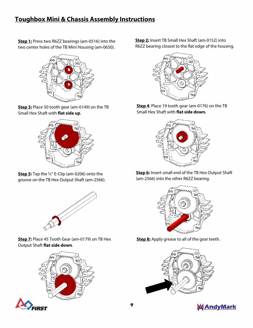
Toughbox Mini & Chassis Assembly Instructions
Step 1: Press two R6ZZ bearings (am-0516) into the two center holes of the TB Mini Housing (am-0650).
Step 4: Place 19 tooth gear (am-0176) on the TB Small Hex Shaft with flat side down.
Step 2: Insert TB Small Hex Shaft (am-0152) into R6ZZ bearing closest to the flat edge of the housing.
Step 3: Place 50 tooth gear (am-0149) on the TB Small Hex Shaft with flat side up.
Step 6: Insert small end of the TB Hex Output Shaft (am-2566) into the other R6ZZ bearing.
Step 5: Tap the ½” E-Clip (am-0206) onto the groove on the TB Hex Output Shaft (am-2566).
Step 7: Place 45 Tooth Gear (am-0179) on TB Hex Output Shaft flat side down.
Step 8: Apply grease to all of the gear teeth.
9
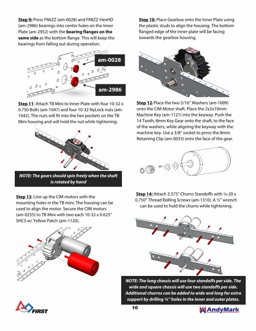
Step 12: Place the two 5/16” Washers (am-1009) onto the CIM Motor shaft. Place the 2x2x10mm Machine Key (am-1121) into the keyway. Push the 14 Tooth, 8mm Key Gear onto the shaft, to the face of the washers, while aligning the keyway with the machine key. Use a 3/8” socket to press the 8mm Retaining Clip (am-0033) onto the face of the gear.
Step 9: Press FR6ZZ (am-0028) and FR8ZZ-HexHD (am-2986) bearings into center holes on the Inner Plate (am-2952) with the bearing flanges on the same side as the bottom flange. This will keep the bearings from falling out during operation.
Step 14: Attach 3.375” Churro Standoffs with ¼-20 x 0.750” Thread Rolling Screws (am-1310). A ½” wrench
can be used to hold the churro while tightening.
Step 10: Place Gearbox onto the Inner Plate using the plastic studs to align the housing. The bottom flanged edge of the inner plate will be facing towards the gearbox housing.
Step 11: Attach TB Mini to Inner Plate with four 10-32 x 0.750 Bolts (am-1047) and four 10-32 NyLock nuts (am-1042). The nuts will fit into the hex pockets on the TB Mini housing and will hold the nut while tightening.
Step 13: Line up the CIM motors with the mounting holes in the TB mini. The housing can be used to align the motor. Secure the CIM motors (am-0255) to TB Mini with two each 10-32 x 0.625” SHCS w/ Yellow Patch (am-1120).
NOTE: The gears should spin freely when the shaft is rotated by hand
NOTE: The long chassis will use four standoffs per side. The wide and square chassis will use two standoffs per side.
Additional churros can be added to wide and long for extra support by drilling ¼” holes in the inner and outer plates.
am-0028
am-2986
10

Step 16: Place the Hex Spacer (am-1305) onto the TB Hex Output shaft and press into the pulley. The shaft will help to align the spacer hex with the wheel hub hex.
Step 15: Place an Inner Wheel Assembly onto the TB Hex Output shaft with the hub facing towards the inner plate.
Step 18: There are different axle bolt locations for the different chassis configurations. Slide an axle bolt (am-1297) into the correct axle hole on the outer plate.
Step 17: Press the FR8ZZ-HexHD Bearing (am-2986) into the center hole of the Outer Plate (am-2951). The bearing flange will be on the same side as the plate flanges to ensure the bearing does not fall out during operation.
Step 19: Add a long spacer (am-1307), wheel assembly and short spacer (am-1306) to the axle bolt. The shorter 0.28” (am-1306) spacer is used on the pulley side of the wheel.
Step 20: For the second wheel on this side, the spacer and wheel orientation is reversed to allow one pulley on either side to line up with a center wheel assembly pulley. The front and back wheels will be in opposite orientations.
am-1305
am-1307
am-1306
am-1306
am-1307
11

Step 25: Make sure to cut both the end plate and center churros to the proper length for your chosen chassis in order to comply with 2015 FRC robot rules. Attach end plates to the drive modules using 10-32 x 0.5” SHCS.
Step 24: You have made one side drive module. Repeat steps 1-23 to create the other drive module.
Step 21: Carefully line up and place the outer plate assembly onto the inner plate assembly. The axle bolts will slide through corresponding bolt holes on the inner plate and the TB mini shaft will slide through the FR8ZZ-HexHD bearing on the outer plate. Make sure to place belts around the wheel pulleys before securing outer plate.
Step 26: Add the long Churro Tubes (am-2974) and 2x3 Hole Brackets (am-2954) as stiffeners across the robot frame. Feel free to move these to other holes to accommodate electronics and/or other mechanisms.
Step 22: Finger tighten the axle bolts with the 3/8-16 NyLock Nuts (am-1054) to secure the assembly. Attach the Outer Plate to the churro standoffs using 1/4”-20 x 0.750” Thread Rolling Screws (am-1310).
Step 23: Tighten down axle bolts. The spacers should be flush with the inside plate but the wheel should still easily turn.
NOTE: The belts should be parallel to the side plates.
The long chassis requires 170 tooth belts (am-2570). The wide chassis requires 131 tooth belts (am-2571).
The square chassis requires 151 tooth belts (am-2706).
NOTE: The long chassis will use 6 screws per corner. The wide and square configurations will use 5 screws per corner. am-2954
am-2974
12