usc general standard...
TRANSCRIPT
USC General Standard Guidelines
Table of Contents 1 INTRODUCTION ...........................................................................................1 2 SET ORGANIZATION ...................................................................................1
2.1 Set Sheet Numbering .............................................................................1 2.2 Set Sheet Naming ..................................................................................3 2.3 File Naming ............................................................................................3 2.4 Sheet Size ..............................................................................................3
3 SET CONTENTS ...........................................................................................4
3.1 Sheet Index ............................................................................................4 3.2 Titleblock ................................................................................................4 3.3 Viewport Scale........................................................................................4 3.4 Key Plan .................................................................................................4 3.5 North Arrow ............................................................................................5 3.6 Overall Floor Plans .................................................................................5
4 SPECIFICATIONS.........................................................................................6 5 PLAN DEFINITIONS......................................................................................7
5.1 Demolition Plans.....................................................................................7 5.2 Floor Plans .............................................................................................7 5.3 Reflected Ceiling Plans...........................................................................7 5.4 Plans with Raised Floors ........................................................................7
6 Set Definitions and Expectations: ..................................................................9
6.1 Schematic Design Drawings (SD) ..........................................................9 6.1.1 Schematic Design Drawing Expectations (By Trade) ....................10
6.1.1.1 Architectural ...............................................................................10 6.1.1.2 Mechanical.................................................................................10 6.1.1.3 Electrical ....................................................................................10 6.1.1.4 Fire Alarm ..................................................................................10 6.1.1.5 Plumbing....................................................................................10 6.1.1.6 Structural ...................................................................................10
6.2 Design Development Drawings (DD)....................................................11 6.2.1 Design Development Drawing Expectations (By Trade)................12
6.2.1.1 Architectural ...............................................................................12 6.2.1.2 Mechanical.................................................................................12 6.2.1.3 Electrical ....................................................................................13 6.2.1.4 Fire Alarm ..................................................................................13 6.2.1.5 Plumbing....................................................................................14 6.2.1.6 Structural ...................................................................................14
6.3 Construction Documents (CD)..............................................................15 6.3.1 Construction Document Drawing Expectations (By Trade)............16
6.3.1.1 Architectural ...............................................................................16
USC General Standard Guidelines Spring 2008
6.3.1.2 Mechanical.................................................................................16 6.3.1.3 Electrical ....................................................................................17 6.3.1.4 Fire Alarm ..................................................................................17 6.3.1.5 Plumbing....................................................................................18 6.3.1.6 Structural ...................................................................................18
6.4 Bid Documents .....................................................................................19 6.5 Plan Check Documents ........................................................................19 6.6 Addendums ..........................................................................................19 6.7 Bulletins ................................................................................................20 6.8 Coordination Drawings .........................................................................20 6.9 As-Built Drawings .................................................................................21
USC General Standard Guidelines Spring 2008
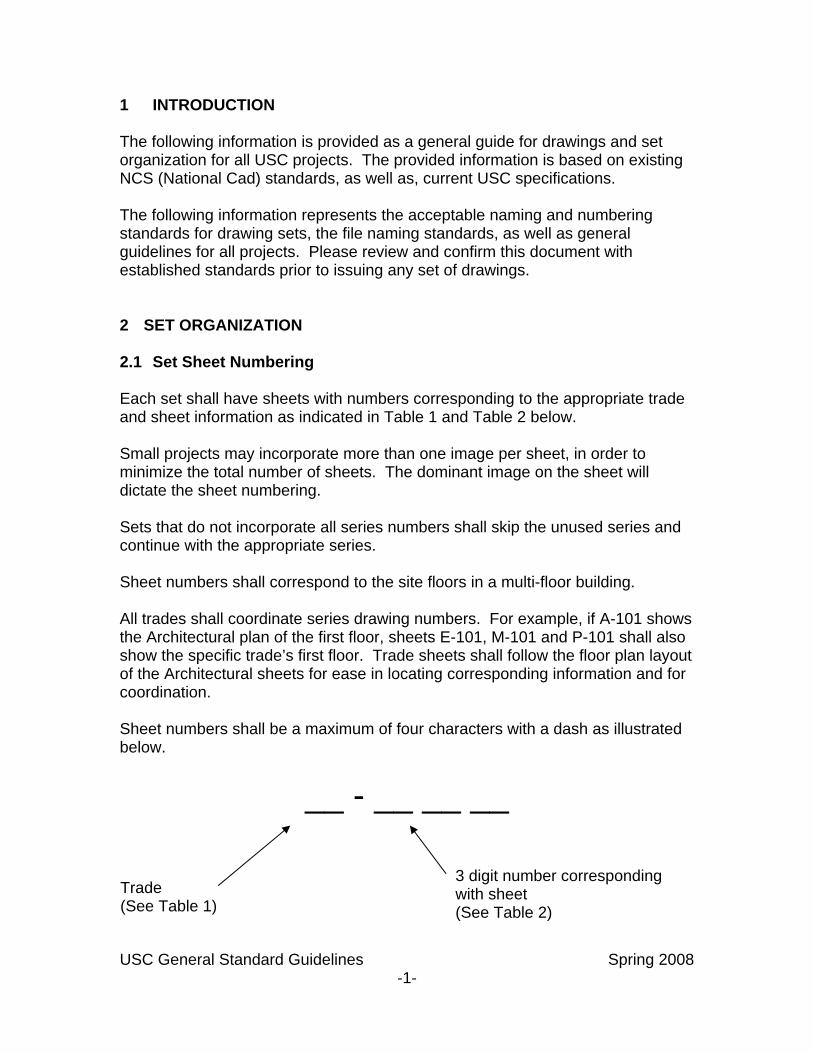
1 INTRODUCTION The following information is provided as a general guide for drawings and set organization for all USC projects. The provided information is based on existing NCS (National Cad) standards, as well as, current USC specifications. The following information represents the acceptable naming and numbering standards for drawing sets, the file naming standards, as well as general guidelines for all projects. Please review and confirm this document with established standards prior to issuing any set of drawings. 2 SET ORGANIZATION 2.1 Set Sheet Numbering Each set shall have sheets with numbers corresponding to the appropriate trade and sheet information as indicated in Table 1 and Table 2 below. Small projects may incorporate more than one image per sheet, in order to minimize the total number of sheets. The dominant image on the sheet will dictate the sheet numbering. Sets that do not incorporate all series numbers shall skip the unused series and continue with the appropriate series. Sheet numbers shall correspond to the site floors in a multi-floor building. All trades shall coordinate series drawing numbers. For example, if A-101 shows the Architectural plan of the first floor, sheets E-101, M-101 and P-101 shall also show the specific trade’s first floor. Trade sheets shall follow the floor plan layout of the Architectural sheets for ease in locating corresponding information and for coordination. Sheet numbers shall be a maximum of four characters with a dash as illustrated below.
__ - __ __ __
USC General Standard Guidelines Spring 2008 -1-
Trade (See Table 1)
3 digit number corresponding with sheet (See Table 2)
USC General Standard Guidelines Spring 2008 -2-
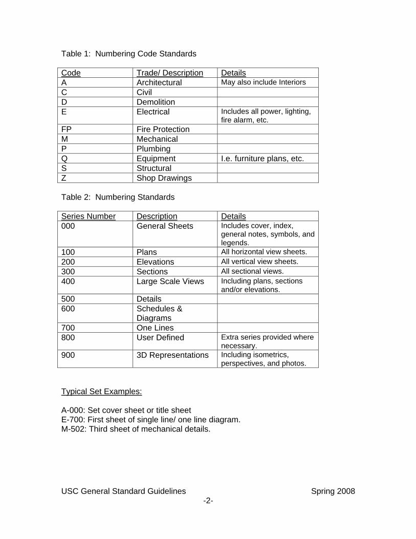
Table 1: Numbering Code Standards Code Trade/ Description DetailsA Architectural May also include Interiors C Civil D Demolition E Electrical Includes all power, lighting,
fire alarm, etc. FP Fire Protection M Mechanical P Plumbing Q Equipment I.e. furniture plans, etc. S Structural Z Shop Drawings Table 2: Numbering Standards Series Number Description Details000 General Sheets Includes cover, index,
general notes, symbols, and legends.
100 Plans All horizontal view sheets. 200 Elevations All vertical view sheets. 300 Sections All sectional views. 400 Large Scale Views Including plans, sections
and/or elevations. 500 Details 600 Schedules &
Diagrams
700 One Lines 800 User Defined Extra series provided where
necessary. 900 3D Representations Including isometrics,
perspectives, and photos. Typical Set Examples: A-000: Set cover sheet or title sheet E-700: First sheet of single line/ one line diagram. M-502: Third sheet of mechanical details.
USC General Standard Guidelines Spring 2008 -3-
2.2 Set Sheet Naming Sheets shall be named in accordance with the trade and information depicted on the sheet. For multi-story buildings, the floor number shall be indicated in the sheet name, regardless if the specific project involves only one of the floors. Whether the number of the floor is spelled out or written as a number should be coordinated by the Architect across all trades. Naming shall be as consistent as possible across all trades for ease of coordination. 2.3 File Naming Corresponding .dwg files (and .pdf files, where applicable) shall have the same file name as sheet number. File names shall also include the sheet name. For example, sheet A-101 will be found in file A101_Basement Floor Plan.dwg. The file name may also include the specific USC project number for clarification. 2.4 Sheet Size Only one of two USC standard size sheets will be accepted: 24 x 36 or 30 x 42. The sheet size for the project shall be determined by the Architect and/or the Project Manager. Sheet sizes shall be consistent throughout the entire project drawing set.

USC General Standard Guidelines Spring 2008 -4-
3 SET CONTENTS 3.1 Sheet Index All sets shall have a sheet index (drawing list) on the first page of each trade. The sheet index shall correspond to all sheets provided by that trade. The trade set shall be arranged in the order of the sheet index. The title or cover sheet to the set (for typical jobs, sheet A-000) shall have a comprehensive sheet index including all trades and all sheets, listed in the order that the set is arranged. 3.2 Titleblock The titleblock layout and design shall be the standard USC titleblock. All trades shall receive a copy of the titleblock to incorporate into individual drawings. The Architect or Project Manager shall have the responsibility of providing each trade with updated titleblocks as necessary. The USC standard titleblock includes the USC logo, the building name, the building address, and the USC project number. 3.3 Viewport Scale Floor plans shall be scaled to 1/8” = 1’-0”. Enlarged sections or areas shall be scaled to 1/4” = 1’-0”. This standard shall be used unless otherwise specified in the beginning of the project. 3.4 Key Plan Projects with multiple floors and or areas, or with enlarged sections on separate sheets, shall have key plans located in the titleblock. Key plans shall show the entire building, shall indicate the area or scope of work, and shall have shaded areas indicating where in the building the section depicted on the sheet is located. The key plan and shading shall be the responsibility of the Architect or lead trade. The Architect (or lead trade) shall provide each trade with the necessary key plan and shading. Each trade shall ensure that the shading is consistent with the information being depicted on each sheet. Sheets that do not depict areas of the building may display a non-shaded key plan or may have no key plan shown at all. All trades must be coordinated as to which type of key plan to provide. If the Electrical panel schedules do not show a key plan, then the Mechanical details shall not show a key plan either.
USC General Standard Guidelines Spring 2008 -5-
Key plans shall be updated and coordinated through the Architect or lead trade. Campus key plans should also be used on the cover sheet. 3.5 North Arrow A North Arrow shall be provided on every floor plan for reference. The North Arrow shall be part of the backgrounds provided to all trades by the Architect. The North Arrow may also indicate “project” north, where necessary. The North Arrow shall not be shown on sheets that do not depict any portion of the building or area. For example, single lines, details, riser diagrams, general sheets, etc, shall not have a north arrow. 3.6 Overall Floor Plans Projects with multiple partial sheets for each floor shall include an overall floor plan in each set. The overall floor plan will be located as the first sheet for each floor and shall depict the complete floor.
USC General Standard Guidelines Spring 2008 -6-
4 SPECIFICATIONS The issuance of book specifications or sheet specifications will be determined on a project by project basis. All trades will be required to follow whichever specification decision is made. Where applicable, sheet specifications shall be part of the 000 series drawings for all trades. (See Table 2 for clarification). Book specifications shall be coordinated through the Architect and shall be provided as one coordinated all inclusive trade specifications package. Specifications, regardless of the type, shall not be vendor specific specifications. Specifications shall not have any blank spaces or multiple choices. Each specification provided for the project shall be complete before submission for review and approval.
USC General Standard Guidelines Spring 2008 -7-
5 PLAN DEFINITIONS 5.1 Demolition Plans Projects that have as part of the scope of work any type of redesign of an existing space shall have demolition drawings included in the set. Demolition drawings shall define which areas and or equipment will be affected by the scope of work. Equipment, devices, pipes, and/or other MEP items shall be shown with delineations as existing to remain (E), existing to be relocated (RL), or existing to be removed (R). Item(s) that will be relocated shall have marking indicating where the item(s) will be moved to. Demolition drawings shall be trade specific. Sets shall include any and all trade’s demolition drawings associated with the project, as necessary. 5.2 Floor Plans Floor plans shall be trade specific. Each trade shall have floor plans that accurately and completely describe that trade’s work within the scope of the project. Floor plans shall depict items that are a part of the floor, including under raised floors, furniture systems, wall items, and the like. Floor plans shall show only one trade information per sheet. Items on the floor plan shall be coordinated previous to plotting the plan. 5.3 Reflected Ceiling Plans Reflected Ceiling Plans shall be a part of any set that includes work in any type of ceiling. Each trade shall include a RCP as necessary to depict work for that trade in the ceiling. The RCP shall show only work being performed at or above the ceiling. RCPs should not show floor work unless necessary for coordination. Furniture may be acceptable on RCPs for coordination and location purposes. RCPs shall show only one trade information per sheet. RCPs shall show the ceiling grid, where applicable. 5.4 Plans with Raised Floors Projects that include areas with raised floors shall include the floor layout in some, if not all, of the floor plans. Raised floors shall not be depicted as part of the reflected ceiling plans. All trades shall show the raised floor area as part of its floor plan for coordination.
USC General Standard Guidelines Spring 2008 -8-
Some trades may need to provide an additional sheet in order to adequately show the raised floor area.
USC General Standard Guidelines Spring 2008 -9-
6 Set Definitions and Expectations: 6.1 Schematic Design Drawings (SD) Schematic design drawings determine the general scope, preliminary design, scale, and relationships between the components of the project. The objective is to develop a clearly defined design with a comprehensive scope, budget, and schedule. Written support material shall be included to define design parameters. Documentation shall include basic material lists and itemized cost estimates for the proposed work. The Schematic Design phase is used to coordinate the design with the functional requirements of the users. Each trade is expected to provide details supporting the SD objective both in narrative and drawing form. General deliverables include:
• General Architectural drawings and site plan • Electrical single line drawings • Floor plans identifying room locations and required programming space
layout • Mechanical and Plumbing riser diagrams • General equipment lists • Building utilities and preliminary utility site plan • Preliminary equipment rooms (such as mechanical, electrical, penthouse,
equipment yard, etc.) • Schematic narrative • Outline specifications
USC General Standard Guidelines Spring 2008 -10-
6.1.1 Schematic Design Drawing Expectations (By Trade) 6.1.1.1 Architectural
• Preliminary Demolition drawings • Initial building layout including site plan • Floor plans identifying room locations and required programming space
layout 6.1.1.2 Mechanical
• Preliminary Demolition drawings • Riser diagram(s) • General equipment list(s) • Building utilities and preliminary utility site plan • Preliminary equipment room requirements and layout
6.1.1.3 Electrical
• Preliminary Demolition drawings • Single Line diagram(s) • General equipment list(s) • Building utilities and preliminary utility site plan • Preliminary equipment room requirements and layout
6.1.1.4 Fire Alarm
• Preliminary Demolition drawings • Riser diagram(s) • General equipment list(s) • Preliminary equipment room requirements and layout
6.1.1.5 Plumbing
• Preliminary Demolition drawings • Riser diagram(s) • General equipment list(s) • Building utilities and preliminary utility site plan • Preliminary equipment room requirements and layout
6.1.1.6 Structural
• Preliminary floor plans showing locations of columns, bracing, or shear walls
• Identify major building systems including gravity, lateral, and foundation elements where applicable.
USC General Standard Guidelines Spring 2008 -11-
6.2 Design Development Drawings (DD) The Design Development phase refines the scope of work previously approved in the SD phase. In the DD phase, the project is developed to detail a coordinated description of the entire project. Design elements including equipment, fire protection, mechanical, electrical, structural, telecommunications, and plumbing systems are coordinated through scaled plans and detailed elevations. Changes to the project’s scope or program past this point could potentially impact the project’s budget and schedule. All program requirements shall be integrated into the design. The DD drawings are used to get an initial project construction estimate. General deliverables for all trades involved include:
• Complete set including rough outlines of all details, fixtures, major equipment.
• Location of all major equipment for all trades including conduit/shaft/pipe routing for initial coordination.
• Specifications • Floor plans should be finalized regarding programming space
requirements. • Initial exiting strategy shall be developed along with code required wall
types and doors. • Coordination of utility points of connection • Equipment selections and schedules
USC General Standard Guidelines Spring 2008 -12-
6.2.1 Design Development Drawing Expectations (By Trade) 6.2.1.1 Architectural
• Complete demolition drawings including notes • Complete drawing set including rough outlines of all details, fixtures,
hardware. • Initial Specifications • General notes • Finalized programmed space plan for floor plans • Initial exiting strategy shall be developed along with code required wall
types and doors. • Coordination of utility points of connection • Initial coordination for locations of all major equipment for all trades
including conduit/shaft/pipe routing. 6.2.1.2 Mechanical
• Complete demolition drawings including notes • Initial analysis, tabulations, and notes for HVAC loads, air volumes, and
exhaust and make up air requirements • General notes • Initial Specifications • Initial equipment schedules indicating capacities, weights, grades and
strengths, locations, and electrical requirements; including CRACs, cooling towers, chillers, boilers, storage tanks, etc.
• Floor Plans showing: • Location and size of all main components of mechanical equipment • Preliminary description of sequence of operation for CRAC units,
condensers, makeup air system, exhaust air system, etc. • HVAC zones • Diffuser and VAV box locations and sizes • Location of all pipe and duct shafts • Chilled and condenser water piping mains • Hot water piping (if any) • Fire dampers • Air and water flow diagrams, including: • Chilled water system flow diagrams with sequence of operation and
location of control sensors • Condenser water system flow diagrams with sequence of operation and
location of control sensors • Makeup water system flow diagrams with sequence of operation and
location of control sensors
USC General Standard Guidelines Spring 2008 -13-
6.2.1.3 Electrical • Complete demolition drawings including notes • Initial analyses, tabulations and notes identifying all electrical loads • Schedules/lists of equipment and materials – including grades and
strengths • Preliminary light fixture schedule(s) • Initial panel schedules with preliminary sizes • Site plans showing location of serving utility transformer, utility service
entrance and standby generator • Floor plans showing: • Preliminary locations of general use receptacles • Preliminary lighting layout and switch locations • Location and dimensions of main switchgear, transformers, power panels,
meters, generator switchboard, ATSs, UPS modules, batteries, PDUs, RPCs, etc.
• Single line diagram(s) • Preliminary size of main switchgear, transformers, switchboards, power
panels, standby generator, UPS equipment, batteries, PDUs, RPCs, etc. • Preliminary size of feeders and conduit for all connections • Preliminary over-current protective device sizes • Preliminary AIC ratings for equipment and devices • Preliminary grounding system diagram with conductor sizes • Preliminary lightning protection system diagram
6.2.1.4 Fire Alarm
• Complete demolition drawings including notes • Initial analyses, tabulations and notes identifying water loads for the fire
protection system, including fire pump size • General notes • Schedules/lists of equipment and materials – including grades and
strengths • Floor plans showing: • Location of main components of fire protection equipment, i.e. valves,
risers, etc. • Initial piping diagrams/patterns and water sources for coordination • Sensor/alarm locations
USC General Standard Guidelines Spring 2008 -14-
6.2.1.5 Plumbing • Complete demolition drawings including notes • Initial analysis (as needed) identifying water loads, sewer loads, and gas
loads • General notes • Schedules of fixtures indicating unit loads, water loads, gas loads, etc. • Schedules indicating capacities, grades and strengths, location, and
electrical requirements for water heaters, booster pumps, etc. • Floor plans showing: • Location and size of major equipment • Location of service pipe and connection sizes and requirements • Size and location of all underground and aboveground tanks • Location of gas meter (as needed) • Locate main sewer and storm drain lines leaving the building (as needed) • Storm water systems – including all roof and overflow drains (as needed) • Sanitary system (as needed) • Domestic water – hot and cold • Gas piping • Fuel oil storage system • Makeup water system • Flow diagrams: • Initial piping flow diagrams with all valves and components to and from
makeup water system for coordination • Initial piping flow diagrams with valves and components to and from fuel
oil system for coordination
6.2.1.6 Structural • Demolition drawings and notes, where applicable • General notes and typical detail sheets • Foundation plan showing: • Sizes of columns • Wall footings • Framing plans for floors and roofs detailing the main framing • Elevations of braced frames, moment frames, and shear walls (as
applicable) • Notes covering items not shown in the set (especially if set will be used for
pricing purposes) • Preliminary specifications or mark-ups of Architectural specs - Structural
sections.
USC General Standard Guidelines Spring 2008 -15-
6.3 Construction Documents (CD) The final design phase is the CD phase. Construction Documents are a complete and coordinate set of drawings identifying all trades necessary for the project and encompassing all items related to the desired final state of the building. General deliverables for this phase include:
• Complete specifications • Complete drawings showing all of the necessary equipment,
conduit/shaft/piping, and coordination between trades. • Detailed MEP distribution and sizes of appurtenances
USC General Standard Guidelines Spring 2008 -16-
6.3.1 Construction Document Drawing Expectations (By Trade) 6.3.1.1 Architectural
• Complete demolition drawings including notes • Complete drawing set including all details, fixtures, and hardware. • Complete specifications • Finalized general notes • Finalized exiting strategy including code required wall types and doors. • Finalized utility points of connection • Finalized coordinated locations of all major equipment for all trades • Finalized lighting and light fixture schedule
6.3.1.2 Mechanical
• Complete demolition drawings including notes • Verification analysis, tabulations, and notes for HVAC loads, air volumes,
and exhaust and make up air requirements • Finalized general notes • Complete specifications • Complete equipment schedules indicating capacities, weights, grades and
strengths, locations, and electrical requirements; including CRACs, cooling towers, chillers, boilers, storage tanks, etc.
• Floor Plans showing: • Location and size of all main components of mechanical equipment • Describe sequence of operation for CRAC units, condensers, makeup air
system, exhaust air system, etc. • HVAC zones • Diffuser and VAV box locations and sizes • Location of all pipe and duct shafts • Chilled and condenser water piping mains • Hot water piping (if any) • Fire dampers • Air and water flow diagrams, including: • Chilled water system flow diagrams with sequence of operation and
location of control sensors • Condenser water system flow diagrams with sequence of operation and
location of control sensors • Makeup water system flow diagrams with sequence of operation and
location of control sensors
USC General Standard Guidelines Spring 2008 -17-
6.3.1.3 Electrical • Complete demolition drawings including notes • Verification analyses, tabulations and notes identifying all electrical loads • Finalized schedules/lists of equipment and materials – including grades
and strengths • Complete light fixture schedule(s) • Complete general and specific notes • Complete panel schedules • Complete site plans showing location of serving utility transformer, utility
service entrance and standby generator • Floor plans showing: • Locations of general use receptacles in all areas • Complete lighting layout and switch locations • Location and dimensions of main switchgear, transformers, power panels,
meters, generator switchboard, ATSs, UPS modules, batteries, PDUs, RPCs, etc.
• Locations and system power requirements for fire alarms, smoke and life safety control panels, equipment racks, speakers, strobes, horns, detectors, etc.
• Complete single line diagram(s) • Finalized sizes of main switchgear, transformers, switchboards, power
panels, standby generator, UPS equipment, batteries, PDUs, RPCs, etc. • Finalized size of feeders and conduit for all connections • Finalized over-current protective device sizes • Finalized AIC ratings for equipment and devices • Grounding system diagram with conductor sizes • Lightning protection system diagram
6.3.1.4 Fire Alarm
• Complete demolition drawings including notes • Verification analyses, tabulations and notes as needed • Complete general notes • Schedules/lists of equipment and materials – including grades and
strengths • Floor plans showing: • Location of main components of fire protection equipment, i.e. valves,
risers, etc. • Piping diagrams/patterns and water sources • Sensor/alarm locations and connections • Coordination with all trades as necessary
USC General Standard Guidelines Spring 2008 -18-
6.3.1.5 Plumbing • Complete demolition drawings including notes • Verification analysis (as needed) identifying water loads, sewer loads, and
gas loads • Complete general notes • Complete specifications • Schedules of fixtures indicating unit loads, water loads, gas loads, etc. • Schedules indicating capacities, grades and strengths, location, and
electrical requirements for water heaters, booster pumps, etc. • Floor plans showing: • Location and size of major equipment • Location of service pipe and connection sizes and requirements • Size and location of all underground and aboveground tanks • Location of gas meter (as needed) • Locate main sewer and storm drain lines leaving the building (as needed) • Storm water systems – including all roof and overflow drains (as needed) • Sanitary system (as needed) • Domestic water – hot and cold • Gas piping • Fuel oil storage system • Makeup water system • Flow diagrams: • Piping flow diagrams with all valves and components to and from makeup
water system • Piping flow diagrams with valves and components to and from fuel oil
system 6.3.1.6 Structural
• Complete demolition drawings and notes, where applicable • Complete specifications • Complete notes and details • Finalized coordination with other trades as necessary including equipment
weights and finalized locations • Floor plans showing all final information for construction
USC General Standard Guidelines Spring 2008 -19-
6.4 Bid Documents These documents are used by the contractor(s) to determine a maximum price and to set the budget for the construction phase. Bid documents are sent out to multiple general and sub-contractors for pricing. Bid documents should be a complete set of drawings including all trades involve in the project. Specifications should be included in the sets sent for bid. Bid documents should be issued around the same time as the set goes into plan check. 6.5 Plan Check Documents Plan check documents include all documentation necessary to give to the City for review. Each trade is reviewed by the respective department in the City Planning department. Plan check documents should include the latest information and full specifications. 6.6 Addendums Addendums are issued when changes are made to the Construction Documents before they are sent to the contractors for bid. Addendums are issued with a specific number. Areas that have been changed in the drawings shall be clouded and identified with the corresponding Addendum number. For larger projects, Change Lists shall be issued with each Addendum. The change lists shall provide a guide for each trade as to what drawings, and/or specification sections have been changed along with a brief description of the change for reference.
USC General Standard Guidelines Spring 2008 -20-
6.7 Bulletins Bulletins are issued once bids have begun to come back. Like Addendums, Bulletins are numbered and the updated information is clouded for clarity. Bulletins require that budget numbers be reworked depending on the issued changes. For larger projects, Change Lists shall be issued with each Bulletin. The change lists shall provide a guide for each trade as to what drawings, and/or specification sections have been changed along with a brief description of the change for reference. 6.8 Coordination Drawings Coordination Drawings are important during the Construction Phase of the project. Coordination drawings are provided by the General Contractor and reflect actually installed equipment and up-to-date information provided by each sub-contractor. Whenever possible, Coordination Drawings shall be issued in color, with each trade being represented by a specific and consistent color. Coordination drawings may be issued in .pdf and/or hard copy form. Coordination drawings may be issued several times during construction, depending on the complexity of the project.
USC General Standard Guidelines Spring 2008 -21-
6.9 As-Built Drawings As-Built drawings are required at the end of all projects by all trades. The General Contractor is responsible for assembling and distributing complete sets of as-built drawings. As-built drawings shall be provided both in electronic and hard copy forms. These drawings shall indicate the exact installation of all equipment, wire/shaft/pipes, etc related to the job. As-built drawings will mimic the entire drawing set and will serve as future reference by the University. As-built drawings shall include all facets of the building as necessary. Partial or incomplete drawing sets are not acceptable. All As-built drawings shall be drawn in AutoCad, version to be decided upon in the beginning of the project. Electronic As-built drawings shall not be scanned versions of hand drawn plans. Backgrounds and electronic trade drawings shall be provided to the GC and any subs as necessary by the Architect and/or Engineer. Electronic drawings shall have both the Xref-Bind-Insert and Etransmit commands performed upon before sending.