usc’s project revit record requirement execution plan (prxp)...
TRANSCRIPT
Architects – Initial _______
General Contractor – Initial _______
1 Jan 1, 2017 USC – Initial _______
Addendum | PRxP
APPENDIX
USC’s Project Revit Record Requirement
Execution Plan (PRxP) TEMPLATE
FOR
[PROJECT TITLE]
DEVELOPED BY
[AUTHOR COMPAN(IES)]
DATE:
(DATE EXECUTED)
Note: This template is a tool that is provided to assist in the development of USC’s Project Project Revit Record
Requirement Execution Plan (PRxP) as required per contract. It was adapted from the United States Army Core of
Engineers (USACE) BIM”©) Project Execution Plan Template (PxP) Version 2.0., dated 9-13-2012.
Architects – Initial _______
General Contractor – Initial _______
2 Jan 1, 2017 USC – Initial _______
Addendum | PRxP
TABLE OF CONTENTS
SECTION A: PROJECT INFORMATION ......................................................................................................... 3
SECTION B: KEY PROJECT CONTACTS ........................................................................................................ 4
SECTION C: REVIT RECORD MODEL USES .................................................................................................. 5
SECTION D: ORGANIZATIONAL ROLES / STAFFING ....................................................................................... 6
SECTION E: REVIT RECORD MODEL PROCESS DESIGN .................................................................................. 7
SECTION F: REVIT RECORD MODEL PROCESSES AND COLLABORATION PROCEDURES ........................................... 8
SECTION G: QUALITY CONTROL ............................................................................................................. 12
SECTION H: TECHNOLOGICAL INFRASTRUCTURE NEEDS .............................................................................. 13
SECTION I: MODEL ORGANIZATION ........................................................................................................ 14
SECTION J: PROJECT DELIVERABLES ........................................................................................................ 16
SECTION K: MINIMUM MODELING MATRIX (M)3 .................................................................................... 19
SECTION L: ATTACHMENTS ................................................................................................................... 19
SECTION M: JOINT SIGNATURE PAGE ...................................................................................................... 20
NOTE: All text that is grey is for illustrative purposes only and should not be construed as a formalized
response to this execution plan.
Architects – Initial _______
General Contractor – Initial _______
3 Jan 1, 2017 USC – Initial _______
Addendum | PRxP
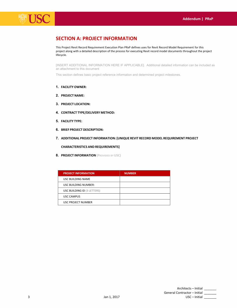
SECTION A: PROJECT INFORMATION
This Project Revit Record Requirement Execution Plan PRxP defines uses for Revit Record Model Requirement for this
project along with a detailed description of the process for executing Revit record model documents throughout the project
lifecycle.
[INSERT ADDITIONAL INFORMATION HERE IF APPLICABLE]. Additional detailed information can be included as an attachment to this document This section defines basic project reference information and determined project milestones.
1. FACILITY OWNER:
2. PROJECT NAME:
3. PROJECT LOCATION:
4. CONTRACT TYPE/DELIVERY METHOD:
5. FACILITY TYPE:
6. BRIEF PROJECT DESCRIPTION:
7. ADDITIONAL PROJECT INFORMATION: [UNIQUE REVIT RECORD MODEL REQUIREMENT PROJECT
CHARACTERISTICS AND REQUIREMENTS]
8. PROJECT INFORMATION (PROVIDED BY USC)
PROJECT INFORMATION NUMBER
USC BUILDING NAME
USC BUILDING NUMBER:
USC BUILDING ID (3 LETTERS)
USC CAMPUS
USC PROJECT NUMBER
Architects – Initial _______
General Contractor – Initial _______
4 Jan 1, 2017 USC – Initial _______
Addendum | PRxP
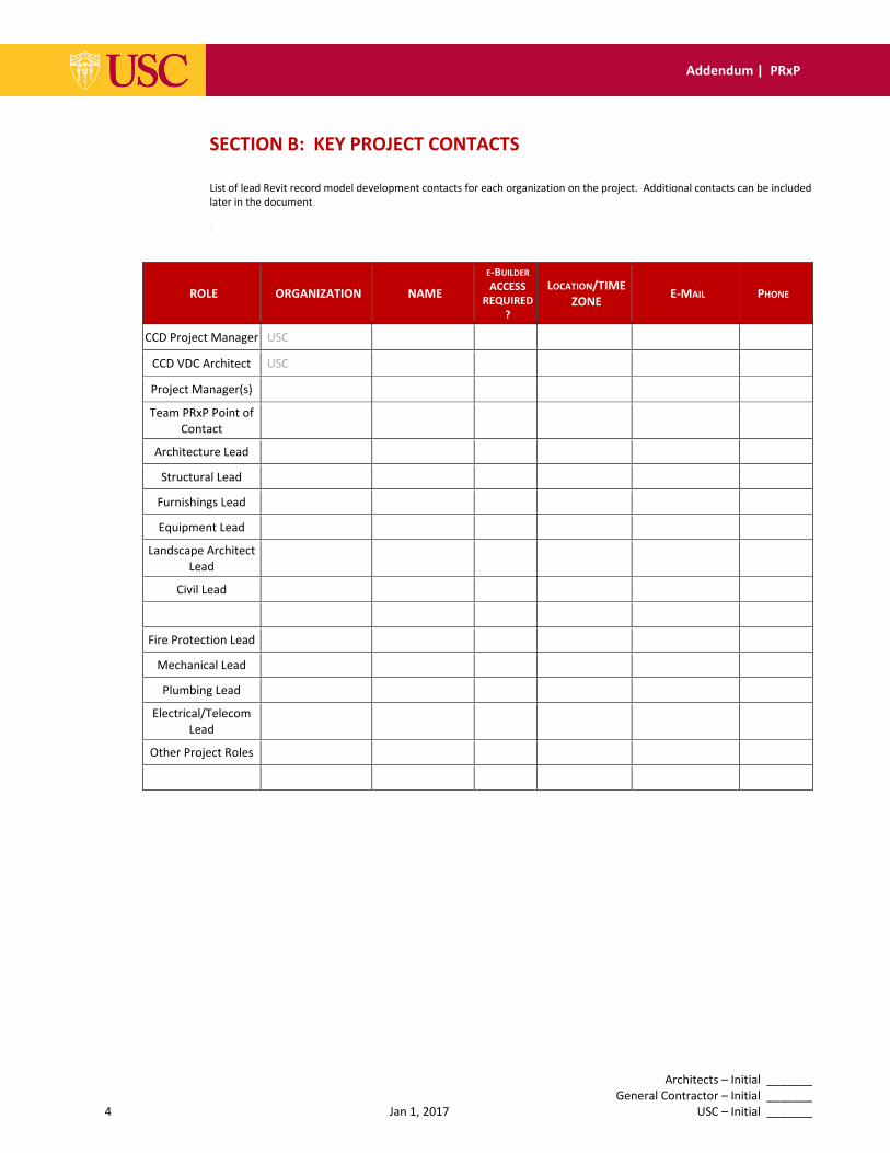
SECTION B: KEY PROJECT CONTACTS
List of lead Revit record model development contacts for each organization on the project. Additional contacts can be included
later in the document.
.
ROLE ORGANIZATION NAME
E-BUILDER
ACCESS
REQUIRED
?
LOCATION/TIME
ZONE E-MAIL PHONE
CCD Project Manager USC
CCD VDC Architect USC
Project Manager(s)
Team PRxP Point of
Contact
Architecture Lead
Structural Lead
Furnishings Lead
Equipment Lead
Landscape Architect
Lead
Civil Lead
Fire Protection Lead
Mechanical Lead
Plumbing Lead
Electrical/Telecom
Lead
Other Project Roles
Architects – Initial _______
General Contractor – Initial _______
5 Jan 1, 2017 USC – Initial _______
Addendum | PRxP
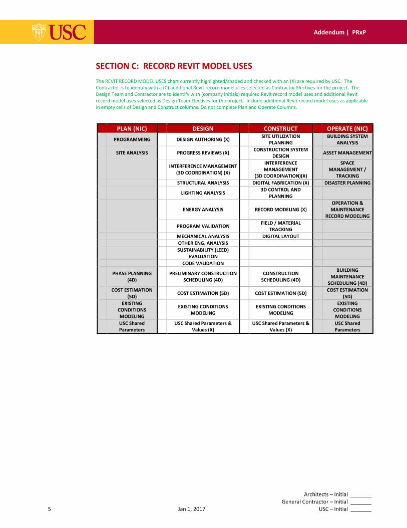
SECTION C: RECORD REVIT MODEL USES
The REVIT RECORD MODEL USES chart currently highlighted/shaded and checked with an (X) are required by USC. The
Contractor is to identify with a (C) additional Revit record model uses selected as Contractor Electives for the project. The
Design Team and Contractor are to identify with (company initials) required Revit record model uses and additional Revit
record model uses selected as Design Team Electives for the project. Include additional Revit record model uses as applicable
in empty cells of Design and Construct columns. Do not complete Plan and Operate Columns.
PLAN (NIC) DESIGN CONSTRUCT OPERATE (NIC)
PROGRAMMING DESIGN AUTHORING (X) SITE UTILIZATION
PLANNING
BUILDING SYSTEM
ANALYSIS
SITE ANALYSIS PROGRESS REVIEWS (X) CONSTRUCTION SYSTEM
DESIGN ASSET MANAGEMENT
INTERFERENCE MANAGEMENT
(3D COORDINATION) (X)
INTERFERENCE
MANAGEMENT
(3D COORDINATION)(X)
SPACE
MANAGEMENT /
TRACKING
STRUCTURAL ANALYSIS DIGITAL FABRICATION (X) DISASTER PLANNING
LIGHTING ANALYSIS 3D CONTROL AND
PLANNING
ENERGY ANALYSIS RECORD MODELING (X)
OPERATION &
MAINTENANCE
RECORD MODELING
PROGRAM VALIDATION FIELD / MATERIAL
TRACKING
MECHANICAL ANALYSIS DIGITAL LAYOUT
OTHER ENG. ANALYSIS
SUSTAINABILITY (LEED)
EVALUATION
CODE VALIDATION
PHASE PLANNING
(4D)
PRELIMINARY CONSTRUCTION
SCHEDULING (4D)
CONSTRUCTION
SCHEDULING (4D)
BUILDING
MAINTENANCE
SCHEDULING (4D)
COST ESTIMATION
(5D) COST ESTIMATION (5D) COST ESTIMATION (5D)
COST ESTIMATION
(5D)
EXISTING
CONDITIONS
MODELING
EXISTING CONDITIONS
MODELING
EXISTING CONDITIONS
MODELING
EXISTING
CONDITIONS
MODELING
USC Shared
Parameters
USC Shared Parameters &
Values (X)
USC Shared Parameters &
Values (X)
USC Shared
Parameters
X
Architects – Initial _______
General Contractor – Initial _______
6 Jan 1, 2017 USC – Initial _______
Addendum | PRxP
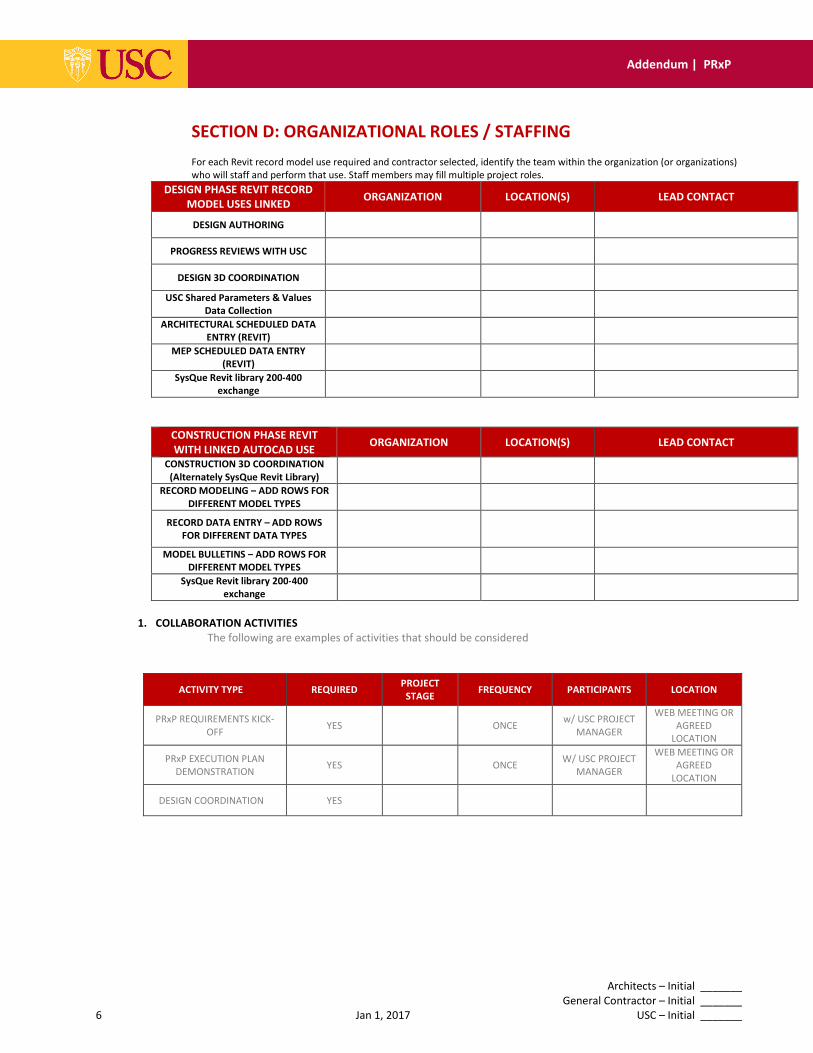
SECTION D: ORGANIZATIONAL ROLES / STAFFING
For each Revit record model use required and contractor selected, identify the team within the organization (or organizations)
who will staff and perform that use. Staff members may fill multiple project roles.
DESIGN PHASE REVIT RECORD
MODEL USES LINKED ORGANIZATION LOCATION(S) LEAD CONTACT
DESIGN AUTHORING
PROGRESS REVIEWS WITH USC
DESIGN 3D COORDINATION
USC Shared Parameters & Values
Data Collection
ARCHITECTURAL SCHEDULED DATA
ENTRY (REVIT)
MEP SCHEDULED DATA ENTRY
(REVIT)
SysQue Revit library 200-400
exchange
CONSTRUCTION PHASE REVIT
WITH LINKED AUTOCAD USE ORGANIZATION LOCATION(S) LEAD CONTACT
CONSTRUCTION 3D COORDINATION
(Alternately SysQue Revit Library)
RECORD MODELING – ADD ROWS FOR
DIFFERENT MODEL TYPES
RECORD DATA ENTRY – ADD ROWS
FOR DIFFERENT DATA TYPES
MODEL BULLETINS – ADD ROWS FOR
DIFFERENT MODEL TYPES
SysQue Revit library 200-400
exchange
1. COLLABORATION ACTIVITIES
The following are examples of activities that should be considered
ACTIVITY TYPE REQUIRED PROJECT
STAGE FREQUENCY PARTICIPANTS LOCATION
PRxP REQUIREMENTS KICK-
OFF YES ONCE
w/ USC PROJECT
MANAGER
WEB MEETING OR
AGREED
LOCATION
PRxP EXECUTION PLAN
DEMONSTRATION YES ONCE
W/ USC PROJECT
MANAGER
WEB MEETING OR
AGREED
LOCATION
DESIGN COORDINATION YES

Architects – Initial _______
General Contractor – Initial _______
7 Jan 1, 2017 USC – Initial _______
Addendum | PRxP
SECTION E: REVIT RECORD MODEL PROCESS DESIGN DEVELOPING REVIT RECORD MODEL
Architects – Initial _______
General Contractor – Initial _______
8 Jan 1, 2017 USC – Initial _______
Addendum | PRxP
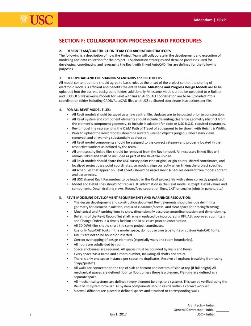
SECTION F: COLLABORATION PROCESSES AND PROCEDURES
2. DESIGN TEAM/CONSTRUCTION TEAM COLLABORATION STRATEGIES
The following is a description of how the Project Team will collaborate in the development and execution of
modeling and data collection for the project. Collaboration strategies and detailed processes used for
developing, coordinating and leveraging the Revit with linked AutoCAD files are defined for the following
purposes.
3. FILE UPLOAD AND FILE SHARING STANDARDS and PROTOCOLS
All model content authors should agree to basic rules at the onset of the project so that the sharing of
electronic models is efficient and benefits the entire team. Milestone and Progress Design Models are to be
uploaded into the current background folder; additionally Milestone Models are to be uploaded to e-Builder
and 360DOCS. Navisworks models for Revit with linked AutoCAD Coordination are to be uploaded into a
coordination folder including CADD/AutoCAD files with UCS to Shared coordinate instructions per file.
4. FOR ALL REVIT MODEL FILES:
• All Revit models should be saved as a new central file. Updates are to be posted prior to construction.
• All Revit system and component elements should include delimiting clearance geometry (distinct from
the element’s component geometry, to include insulation) for code or USC B.O.D. required clearances.
• Revit model line representing the O&M Path of Travel of equipment to be shown with Height & Width.
• Prior to upload the Revit models should be audited, unused objects purged, unnecessary views
removed, and all warning substantially addressed.
• All Revit model components should be assigned to the correct category and properly located in their
respective workset as defined by the team.
• All unnecessary linked files should be removed from the Revit model. All necessary linked files will
remain linked and shall be included as part of the Revit file upload.
• All Revit models should share the USC survey point (the original origin point), shared coordinates, and
localized project base point coordinates, so models align correctly when linking the project specified.
• All schedules that appear on Revit sheets should be native Revit schedules derived from model content
and parameters.
• All USC Shared Revit Parameters to be loaded in the Revit project file with values correctly populated.
• Model and Detail lines should not replace 3D information in the Revit model. (Except: Detail values and
components, Detail drafting views, Room/Area separation lines, 1/2" or smaller joints in panels, etc.)
5. REVIT MODELING DEVELOPMENT REQUIREMENTS AND WARNINGS RESOLUTION:
• The design development and construction document Revit elements should include delimiting
geometry for element insulation, required clearance/access, and clear space for bracing/framing.
• Mechanical and Plumbing lines to show dimensionally accurate centerline location and dimensioning.
• Bulletins of the Revit Record Set shall remain updated by incorporating RFI, ASI, approved submittals
and Change Orders in a timely fashion and in all cases prior to construction.
• All 2D DWG files should share the same project coordinates.
• Use only AutoCAD fonts in the model space; do not use true type fonts or custom AutoCAD fonts.
• XREF’s are not to be bound or inserted.
• Correct overlapping of design elements (especially walls and room boundaries).
• All floors are subdivided by room.
• Space enclosures are required. All spaces must be bounded by walls and floors.
• Every space has a name and a room number, including all shafts and stairs.
• There is only one space instance per space, no duplicates. Resolve all orphans (resulting from using
“copy/paste”).
• All walls are connected to the top of slab at bottom and bottom of slab at top (if full height).All
mechanical spaces are defined floor to floor, unless there is a plenum. Plenums are defined as a
separate space.
• All mechanical systems are defined (every element belongs to a system). This can be verified using the
Revit MEP system browser. All system components should reside within a correct workset.
• Sidewall diffusers are placed in defined spaces and attached to corresponding walls.
Architects – Initial _______
General Contractor – Initial _______
9 Jan 1, 2017 USC – Initial _______
Addendum | PRxP
• Ensure that the Revit MEP file is linked to the Revit architectural file. (This can be checked by using
the Revit System Browse and verifying that the space name and number columns are populated).
• Ensuring that all mechanical zones are defined. Ensure that there are no unassigned components
(View/User Interface/System Browser).
• Mapping MEP Space names to architectural room names.
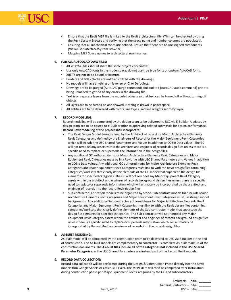
6. FOR ALL AUTODCAD DWG FILES:
• All 2D DWG files should share the same project coordinates.
• Use only AutoCAD fonts in the model space; do not use true type fonts or custom AutoCAD fonts.
• XREF’s are not to be bound or inserted.
• Borders and titles blocks are not transmitted with the drawings.
• No models will have anything on layer zero (0) or Defpoints.
• Drawings are to be purged (AutoCAD purge command) and audited (AutoCAD audit command) prior to
being uploaded to get rid of any errors in the drawing file.
• Text is on separate layers from the modeled objects so that text can be turned off without turning off
objects.
• All layers are to be turned on and thawed. Nothing is drawn in paper space.
• All entities are to be delivered with colors, line types, and line weights set to by layer.
7. RECORD MODELING:
Record modeling will be completed by the design team to be delivered to USC via E-Builder. Updates by
design team are to be posted to e-Builder prior to approving related submittals for design conformance.
Record Revit modeling of the project shall incorporate:
• The Revit Design Model items defined by the Architect of record for Major Architecture Elements
Revit Categories and defined by the Engineers of Record for the Major Equipment Revit Categories
which will include the USC Shared Parameters and Values in addition to COBie Data values. The GC
will not remodel any assets within the architect and engineer of records design files unless there is a
specific need to replace or supersede the information in the design files.
• Any additional GC authored items for Major Architecture Elements Revit Categories and Major
Equipment Revit Categories must be in a Revit file with USC Shared Parameters and Values in addition
to COBie Data values. Any additional GC authored items for Major Architecture Elements Revit
Categories and Major Equipment Revit Categories must link to with the Revit design files containing
categories/worksets that clearly define elements of the GC model that supersede the design file
elements for specified categories. The GC will not remodel any Major Equipment Revit Category
assets within the architect and engineer of records background design files unless there is a specific
need to replace or supersede information which will ultimately be incorporated by the architect and
engineer of records into the record Revit design files.
• Sub-contractor Fabrication models to be organized by scope. Sub-contract models that include Major
Architecture Elements Revit Categories and Major Equipment Revit Categories must use design model
backgrounds. Any additional Sub-contractor authored items for Major Architecture Elements Revit
Categories and Major Equipment Revit Categories must link to with the Revit design files containing
categories/worksets that clearly define elements of the Sub-contractor model that supersede the
design file elements for specified categories. The Sub-contractor will not remodel any Major
Equipment Revit Category assets within the architect and engineer of records background design files
unless there is a specific need to replace or supersede information which will ultimately be
incorporated by the architect and engineer of records into the record design files
8. AS-BUILT MODELING:
As-built model will be completed by the construction team to be delivered to USC via E-Builder at the end
of construction. The As-built models are complimentary to contractor ’s complete As-built mark-up of the
construction documents. The As-built files include all of the categories not included in the USC Shared
Parameter Categories, as the USC Shared Parameters are instead part of the Record Revit models.
9. RECORD DATA COLLECTION:
Record data collection will be performed during the Design & Construction Phase directly into the Revit
models thru Google Sheets or Office 365 Excel. The MEPF data will then be completed after installation
during construction phase per Major Equipment Revit Categories by the GC and subcontractors.
Architects – Initial _______
General Contractor – Initial _______
10 Jan 1, 2017 USC – Initial _______
Addendum | PRxP
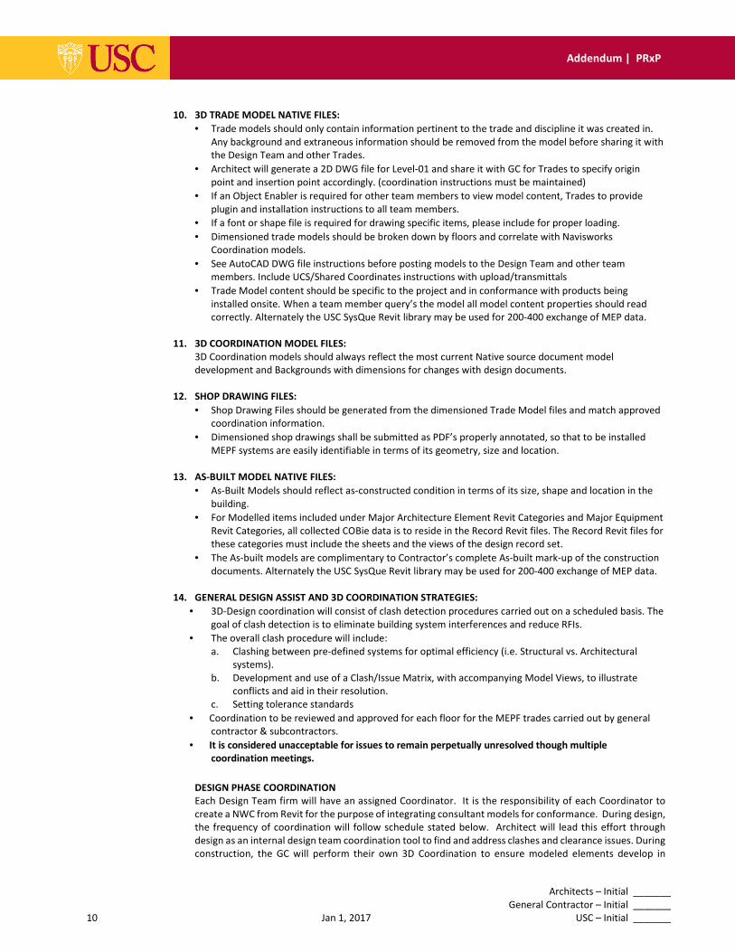
10. 3D TRADE MODEL NATIVE FILES:
• Trade models should only contain information pertinent to the trade and discipline it was created in.
Any background and extraneous information should be removed from the model before sharing it with
the Design Team and other Trades.
• Architect will generate a 2D DWG file for Level-01 and share it with GC for Trades to specify origin
point and insertion point accordingly. (coordination instructions must be maintained)
• If an Object Enabler is required for other team members to view model content, Trades to provide
plugin and installation instructions to all team members.
• If a font or shape file is required for drawing specific items, please include for proper loading.
• Dimensioned trade models should be broken down by floors and correlate with Navisworks
Coordination models.
• See AutoCAD DWG file instructions before posting models to the Design Team and other team
members. Include UCS/Shared Coordinates instructions with upload/transmittals
• Trade Model content should be specific to the project and in conformance with products being
installed onsite. When a team member query’s the model all model content properties should read
correctly. Alternately the USC SysQue Revit library may be used for 200-400 exchange of MEP data.
11. 3D COORDINATION MODEL FILES:
3D Coordination models should always reflect the most current Native source document model
development and Backgrounds with dimensions for changes with design documents.
12. SHOP DRAWING FILES:
• Shop Drawing Files should be generated from the dimensioned Trade Model files and match approved
coordination information.
• Dimensioned shop drawings shall be submitted as PDF’s properly annotated, so that to be installed
MEPF systems are easily identifiable in terms of its geometry, size and location.
13. AS-BUILT MODEL NATIVE FILES:
• As-Built Models should reflect as-constructed condition in terms of its size, shape and location in the
building.
• For Modelled items included under Major Architecture Element Revit Categories and Major Equipment
Revit Categories, all collected COBie data is to reside in the Record Revit files. The Record Revit files for
these categories must include the sheets and the views of the design record set.
• The As-built models are complimentary to Contractor’s complete As-built mark-up of the construction
documents. Alternately the USC SysQue Revit library may be used for 200-400 exchange of MEP data.
14. GENERAL DESIGN ASSIST AND 3D COORDINATION STRATEGIES:
• 3D-Design coordination will consist of clash detection procedures carried out on a scheduled basis. The
goal of clash detection is to eliminate building system interferences and reduce RFIs.
• The overall clash procedure will include:
a. Clashing between pre-defined systems for optimal efficiency (i.e. Structural vs. Architectural
systems).
b. Development and use of a Clash/Issue Matrix, with accompanying Model Views, to illustrate
conflicts and aid in their resolution.
c. Setting tolerance standards
• Coordination to be reviewed and approved for each floor for the MEPF trades carried out by general
contractor & subcontractors.
• It is considered unacceptable for issues to remain perpetually unresolved though multiple
coordination meetings.
DESIGN PHASE COORDINATION
Each Design Team firm will have an assigned Coordinator. It is the responsibility of each Coordinator to
create a NWC from Revit for the purpose of integrating consultant models for conformance. During design,
the frequency of coordination will follow schedule stated below. Architect will lead this effort through
design as an internal design team coordination tool to find and address clashes and clearance issues. During
construction, the GC will perform their own 3D Coordination to ensure modeled elements develop in
Architects – Initial _______
General Contractor – Initial _______
11 Jan 1, 2017 USC – Initial _______
Addendum | PRxP
conformance to the design. The Subcontractors 3D modelled elements information is integrated through
RFI responses and subcontractor submittals which all are incorporated into to the construction documents.
Project Leaders will:
• Provide accurate and complete model content representative of their discipline requirements.
• Review report & take appropriate action to resolve identified clashes within the time frame
specified.
CONSTRUCTION PHASE COORDINATION
All trade contractors participating in coordination shall provide their latest models to the team on an as-
needed basis depending on the current demands of the project activities. The latest models should always
be uploaded to the designated folder and utilize the naming conventions in this PRxP.
The coordination facilitator will update the composite model with the latest information available. System
interferences will be found and reported via clash/interference and dimensioned sections for main runs
moved from x,y,z of Revit design models. This effort will identify space constraints and system conflicts.
These will require each participant to relocate its systems to coordinate with the design, engineering, or
work by other participants. It is anticipated that each participant will have to relocate at least some of its
systems. At the close of each coordination session, a composite model (with clear description for linking UCS
to Revit shared coordinates for each file) will be published and uploaded to the project’s folder.
Coordination Signoff
Coordination of system interference relates to the logical (x,y,z, & invert) dimensioned location of system
runs, not solely adjusting overlapping of clashed objects. When the contractor/subcontractor team has
reached a consensus that the dimensioned building systems are resolved and have provided written
dimensioned guidance of changes to the AE team, then the contractor coordination facilitator will compile a
contractor sign-off. The sign-off will include the composite Revit and AutoCAD subcontractor models that
validate that these coordination models match with the design model dimensions, either shown in the
currently coordinated set or that changes have been agreed to by the AE team for inclusion in the
immediately forthcoming CD bulletin. The sign-off composite model will consist of all the current,
coordinated models, which match subcontractor submittals – include the sign-off date in the file name and
upload the coordinated model(s) (unless otherwise specified, in Navisworks Document, NWD format and
native Revit with linked AutoCAD to the project file sharing site as an archive. A contractor Coordination
Sign-Off Agreement will be completed and executed following the completion of coordination for each area,
zone, or floor to acknowledge that the coordination conforms to the design shown in the developing Revit
record set and has been incorporated as a bulletin into the construction documents.
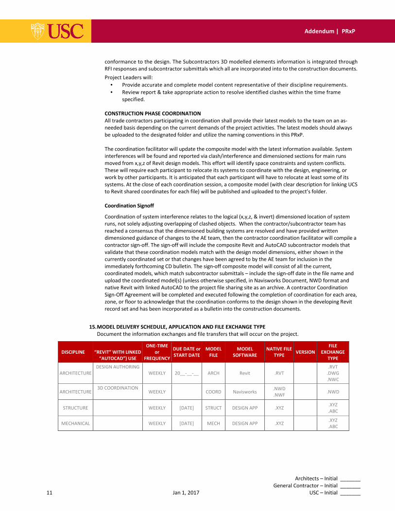
15. MODEL DELIVERY SCHEDULE, APPLICATION AND FILE EXCHANGE TYPE
Document the information exchanges and file transfers that will occur on the project.
DISCIPLINE
“REVIT” WITH LINKED
“AUTOCAD”) USE
ONE-TIME
or
FREQUENCY
DUE DATE or
START DATE
MODEL
FILE
MODEL
SOFTWARE
NATIVE FILE
TYPE
VERSION
FILE
EXCHANGE
TYPE
ARCHITECTURE
DESIGN AUTHORING
WEEKLY 20__-__-__ ARCH Revit .RVT
.RVT
.DWG
.NWC
ARCHITECTURE 3D COORDINATION
WEEKLY COORD Navisworks .NWD
.NWF
.NWD
STRUCTURE
WEEKLY [DATE] STRUCT DESIGN APP .XYZ .XYZ
.ABC
MECHANICAL
WEEKLY [DATE] MECH DESIGN APP .XYZ .XYZ
.ABC
Architects – Initial _______
General Contractor – Initial _______
12 Jan 1, 2017 USC – Initial _______
Addendum | PRxP
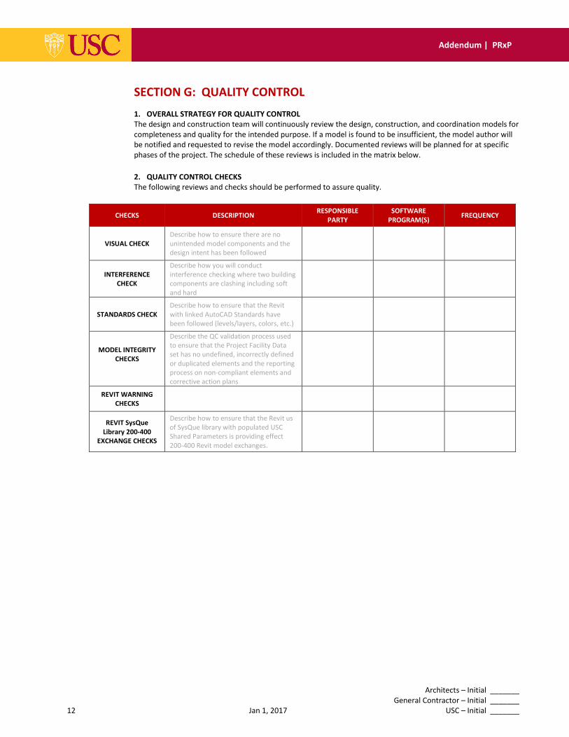
SECTION G: QUALITY CONTROL
1. OVERALL STRATEGY FOR QUALITY CONTROL
The design and construction team will continuously review the design, construction, and coordination models for
completeness and quality for the intended purpose. If a model is found to be insufficient, the model author will
be notified and requested to revise the model accordingly. Documented reviews will be planned for at specific
phases of the project. The schedule of these reviews is included in the matrix below.
2. QUALITY CONTROL CHECKS
The following reviews and checks should be performed to assure quality.
CHECKS DESCRIPTION RESPONSIBLE
PARTY
SOFTWARE
PROGRAM(S) FREQUENCY
VISUAL CHECK
Describe how to ensure there are no
unintended model components and the
design intent has been followed
INTERFERENCE
CHECK
Describe how you will conduct
interference checking where two building
components are clashing including soft
and hard
STANDARDS CHECK
Describe how to ensure that the Revit
with linked AutoCAD Standards have
been followed (levels/layers, colors, etc.)
MODEL INTEGRITY
CHECKS
Describe the QC validation process used
to ensure that the Project Facility Data
set has no undefined, incorrectly defined
or duplicated elements and the reporting
process on non-compliant elements and
corrective action plans
REVIT WARNING
CHECKS
REVIT SysQue
Library 200-400
EXCHANGE CHECKS
Describe how to ensure that the Revit us
of SysQue library with populated USC
Shared Parameters is providing effect
200-400 Revit model exchanges.
Architects – Initial _______
General Contractor – Initial _______
13 Jan 1, 2017 USC – Initial _______
Addendum | PRxP
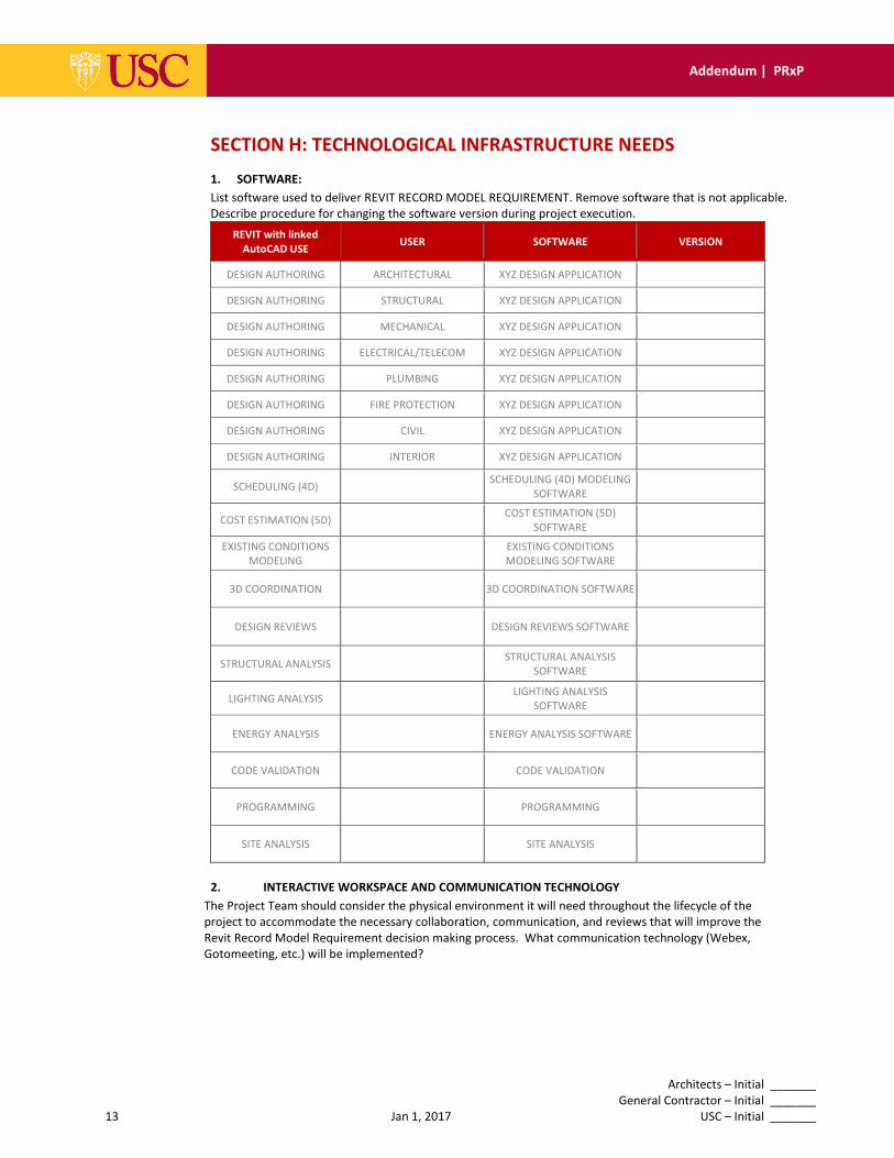
SECTION H: TECHNOLOGICAL INFRASTRUCTURE NEEDS
1. SOFTWARE:
List software used to deliver REVIT RECORD MODEL REQUIREMENT. Remove software that is not applicable.
Describe procedure for changing the software version during project execution.
REVIT with linked
AutoCAD USE USER SOFTWARE VERSION
DESIGN AUTHORING ARCHITECTURAL XYZ DESIGN APPLICATION
DESIGN AUTHORING STRUCTURAL XYZ DESIGN APPLICATION
DESIGN AUTHORING MECHANICAL XYZ DESIGN APPLICATION
DESIGN AUTHORING ELECTRICAL/TELECOM XYZ DESIGN APPLICATION
DESIGN AUTHORING PLUMBING XYZ DESIGN APPLICATION
DESIGN AUTHORING FIRE PROTECTION XYZ DESIGN APPLICATION
DESIGN AUTHORING CIVIL XYZ DESIGN APPLICATION
DESIGN AUTHORING INTERIOR XYZ DESIGN APPLICATION
SCHEDULING (4D) SCHEDULING (4D) MODELING
SOFTWARE
COST ESTIMATION (5D) COST ESTIMATION (5D)
SOFTWARE
EXISTING CONDITIONS
MODELING
EXISTING CONDITIONS
MODELING SOFTWARE
3D COORDINATION 3D COORDINATION SOFTWARE
DESIGN REVIEWS DESIGN REVIEWS SOFTWARE
STRUCTURAL ANALYSIS STRUCTURAL ANALYSIS
SOFTWARE
LIGHTING ANALYSIS LIGHTING ANALYSIS
SOFTWARE
ENERGY ANALYSIS ENERGY ANALYSIS SOFTWARE
CODE VALIDATION CODE VALIDATION
PROGRAMMING PROGRAMMING
SITE ANALYSIS SITE ANALYSIS
2. INTERACTIVE WORKSPACE AND COMMUNICATION TECHNOLOGY
The Project Team should consider the physical environment it will need throughout the lifecycle of the
project to accommodate the necessary collaboration, communication, and reviews that will improve the
Revit Record Model Requirement decision making process. What communication technology (Webex,
Gotomeeting, etc.) will be implemented?
Architects – Initial _______
General Contractor – Initial _______
14 Jan 1, 2017 USC – Initial _______
Addendum | PRxP
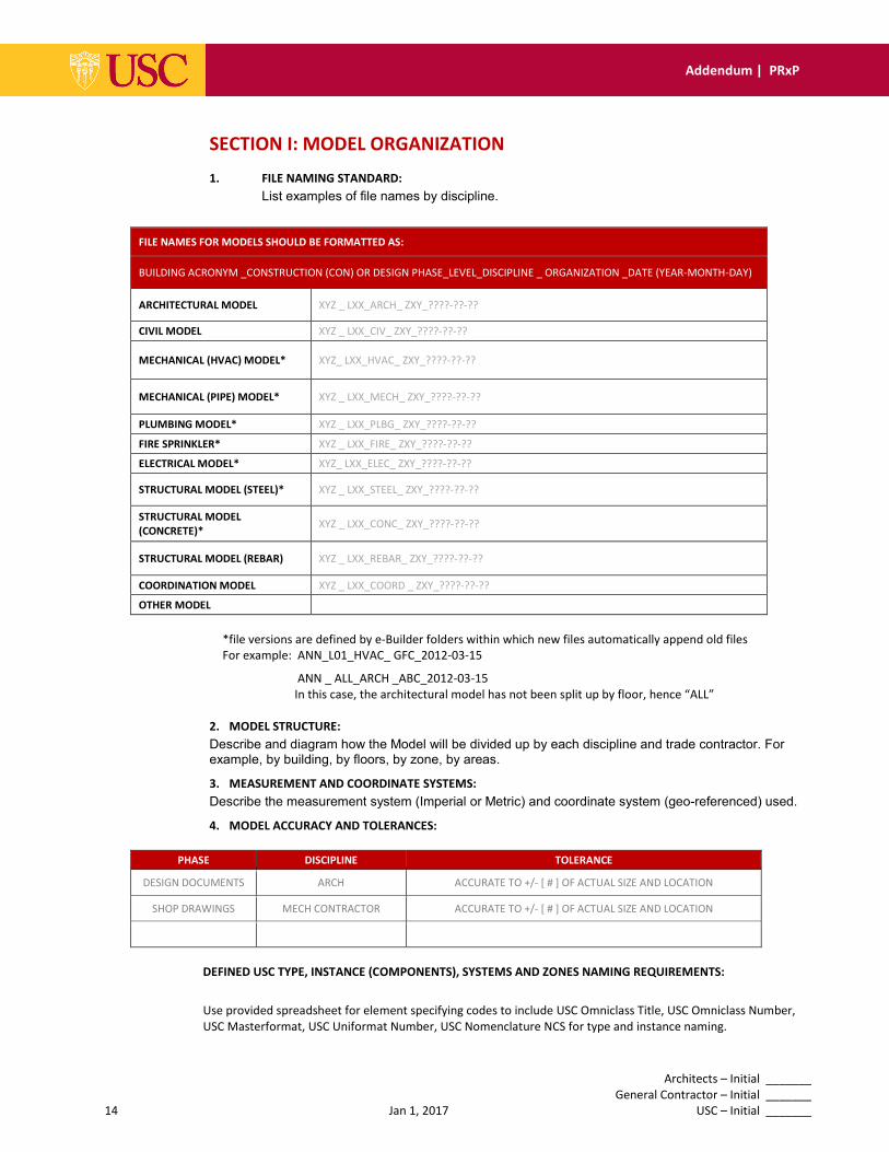
SECTION I: MODEL ORGANIZATION
1. FILE NAMING STANDARD:
List examples of file names by discipline.
FILE NAMES FOR MODELS SHOULD BE FORMATTED AS:
BUILDING ACRONYM _CONSTRUCTION (CON) OR DESIGN PHASE_LEVEL_DISCIPLINE _ ORGANIZATION _DATE (YEAR-MONTH-DAY)
ARCHITECTURAL MODEL XYZ _ LXX_ARCH_ ZXY_????-??-??
CIVIL MODEL XYZ _ LXX_CIV_ ZXY_????-??-??
MECHANICAL (HVAC) MODEL* XYZ_ LXX_HVAC_ ZXY_????-??-??
MECHANICAL (PIPE) MODEL* XYZ _ LXX_MECH_ ZXY_????-??-??
PLUMBING MODEL* XYZ _ LXX_PLBG_ ZXY_????-??-??
FIRE SPRINKLER* XYZ _ LXX_FIRE_ ZXY_????-??-??
ELECTRICAL MODEL* XYZ_ LXX_ELEC_ ZXY_????-??-??
STRUCTURAL MODEL (STEEL)* XYZ _ LXX_STEEL_ ZXY_????-??-??
STRUCTURAL MODEL
(CONCRETE)* XYZ _ LXX_CONC_ ZXY_????-??-??
STRUCTURAL MODEL (REBAR) XYZ _ LXX_REBAR_ ZXY_????-??-??
COORDINATION MODEL XYZ _ LXX_COORD _ ZXY_????-??-??
OTHER MODEL
*file versions are defined by e-Builder folders within which new files automatically append old files
For example: ANN_L01_HVAC_ GFC_2012-03-15
ANN _ ALL_ARCH _ABC_2012-03-15
In this case, the architectural model has not been split up by floor, hence “ALL”
2. MODEL STRUCTURE:
Describe and diagram how the Model will be divided up by each discipline and trade contractor. For example, by building, by floors, by zone, by areas.
3. MEASUREMENT AND COORDINATE SYSTEMS:
Describe the measurement system (Imperial or Metric) and coordinate system (geo-referenced) used.
4. MODEL ACCURACY AND TOLERANCES:
PHASE DISCIPLINE TOLERANCE
DESIGN DOCUMENTS ARCH ACCURATE TO +/- [ # ] OF ACTUAL SIZE AND LOCATION
SHOP DRAWINGS MECH CONTRACTOR ACCURATE TO +/- [ # ] OF ACTUAL SIZE AND LOCATION
DEFINED USC TYPE, INSTANCE (COMPONENTS), SYSTEMS AND ZONES NAMING REQUIREMENTS:
Use provided spreadsheet for element specifying codes to include USC Omniclass Title, USC Omniclass Number,
USC Masterformat, USC Uniformat Number, USC Nomenclature NCS for type and instance naming.

Architects – Initial _______
General Contractor – Initial _______
15 Jan 1, 2017 USC – Initial _______
Addendum | PRxP
Omniclass Table 23 Products are used to digitally code and classify Equipment Families
*for example, 23-27 2111 is the digital code for equipment Axial Flow Compressors
OmniClass Table 21 Elements are used to digitally code and classify Equipment Systems and Zones
*for example, 21-51 31 11 17 is the digital code for equipment system named Domestic Water Distribution
EQUIPMENT TYPE AND INSTANCES (COMPONENTS) NOMENCLATURE1
Naming conventions for equipment types should be succinct, useful and descriptive. The names provided should
allow for easy identification and be easily understood in order to facilitate the operation, repair and maintenance
of USC equipment. USC uses a combination of Industry Standard nomenclature - OmniClass Table 23 Products, the
U.S. National CAD Standards (NCS) 3.1 Module 5: Terms and Abbreviations and an Equipment Operation
Description to name equipment types and instances as illustrated below. Please follow this guide accordingly:
1 If the abbreviation for a piece of equipment is not listed in the National CAD Standards, use the abbreviation
used in your equipment/component schedules instead. For example, a “Fan Powered Box” would be abbreviate as
“FPB”. Use abbreviations as universally understood in the industry
Execution of Equipment Type and Instances (Components) Nomenclature Details on how to populate the
nomenclature in Autodesk® Revit describing the parameters to use, where to place them, and relevant examples,
can be found in the documents entitled "USC Naming Requirements.pptx" and "USC Revit Parameters List.xlsx" in
the “Project Documentation” folder in e-Builder.
An Autodesk® Revit shared parameters file is also available in e-Builder to populate
Autodesk® Revit files with the USC required parameters and/or with the creation of Revit families
Architects – Initial _______
General Contractor – Initial _______
16 Jan 1, 2017 USC – Initial _______
Addendum | PRxP
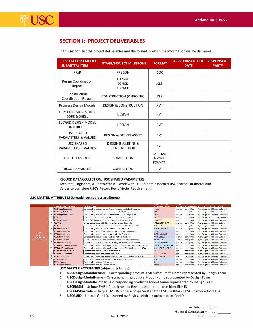
SECTION J: PROJECT DELIVERABLES
In this section, list the project deliverables and the format in which the information will be delivered.
REVIT RECORD MODEL
SUBMITTAL ITEM STAGE/PROJECT MILESTONE FORMAT
APPROXIMATE DUE
DATE
RESPONSIBLE
PARTY
PRxP PRECON .DOC
Design Coordination
Report
100%DD
50%CD
100%CD
.XLS
Construction
Coordination Report CONSTRUCTION (ONGOING) .XLS
Progress Design Models DESIGN & CONSTRUCTION .RVT
100%CD DESIGN MODEL
CORE & SHELL DESIGN .RVT
100%CD DESIGN MODEL
INTERIORS DESIGN .RVT
USC SHARED
PARAMETERS & VALUES DESIGN & DESIGN ASSIST .RVT
USC SHARED
PARAMETERS & VALUES
DESIGN BULLETINS &
CONSTRUCTION .RVT
AS-BUILT MODELS COMPLETION .RVT .DWG
NATIVE
FORMAT
RECORD MODELS COMPLETION .RVT
RECORD DATA COLLECTION: USC SHARED PARAMETERS
Architect, Engineers, & Contractor will work with USC to obtain needed USC Shared Parameter and
Values to complete USC’s Record Revit Model Requirement.
USC MASTER ATTRIBUTES Spreadsheet (object attributes)
USC MASTER ATTRIBUTES (object attributes):
1. USCDesignManufacturer – Corresponding product's Manufacturer's Name represented by Design Team
2. USCDesignModelName – Corresponding product's Model Name represented by Design Team
3. USCDesignModelNumber – Corresponding product's Model Name represented by Design Team
4. USCEMSId – Unique EMS I.D. assigned by Revit as element unique identifier ID
5. USCFMSBarcode – Unique FMS Barcode auto-generated by FAMIS - Obtain FAMIS Barcode from USC
6. USCGUID – Unique G.U.I.D. assigned by Revit as globally unique identifier ID
Architects – Initial _______
General Contractor – Initial _______
17 Jan 1, 2017 USC – Initial _______
Addendum | PRxP
7. USCHWLId – Unique FMS I.D. auto-generated by Honeywell - Obtain I.D. from USC
8. USCInstallContractor – Corresponding product's contracted or subcontracted provider
9. USCInstallManufacturer – Corresponding product's Manufacturer's name installed by Contractor
10. USCInstallModelName – Corresponding product's Manufacturer's name installed by Contractor
11. USCInstallModelNumber – Corresponding product's Manufacturer's name installed by Contractor
12. USCInstallPartName – Discrete product's Part Name, representing one Part of a Model assembly
13. USCInstallPartNumber – Discrete product's Part Number, representing one Part of a Model assembly
14. USCInstallWarrantyDescription – Corresponding product's Warranty Description, Incl. PDF doc name
15. USCInstallWarrantyDuration – Corresponding product's Warranty Duration, Incl. Period Start & End
16. USCMasterFormatNumber – Corresponding product's MasterFormat number, see USC provided table
17. USCOmniClassNumber – Corresponding OmniClass number, see USC provided table
18. USCOmniClassTitle – Corresponding OmniClass description, see USC provided table
19. USCSerialNumber – Unique SerialNumber obtained from Device, Fixture, or Equipment
20. USTagNumber – Corresponding product's FMS tag number
21. USCUniFormatNumber – Corresponding product's UniFormat number, see USC provided table
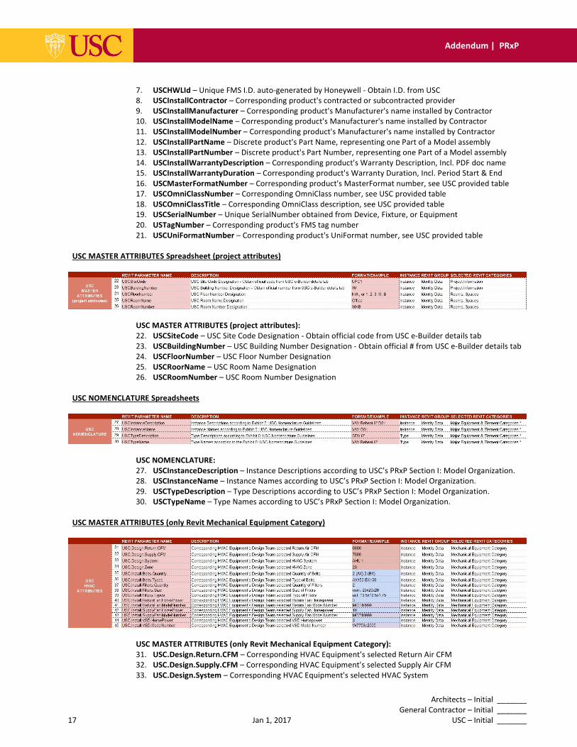
USC MASTER ATTRIBUTES Spreadsheet (project attributes)
USC MASTER ATTRIBUTES (project attributes):
22. USCSiteCode – USC Site Code Designation - Obtain official code from USC e-Builder details tab
23. USCBuildingNumber – USC Building Number Designation - Obtain official # from USC e-Builder details tab
24. USCFloorNumber – USC Floor Number Designation
25. USCRoorName – USC Room Name Designation
26. USCRoomNumber – USC Room Number Designation
USC NOMENCLATURE Spreadsheets
USC NOMENCLATURE:
27. USCInstanceDescription – Instance Descriptions according to USC’s PRxP Section I: Model Organization.
28. USCInstanceName – Instance Names according to USC’s PRxP Section I: Model Organization.
29. USCTypeDescription – Type Descriptions according to USC’s PRxP Section I: Model Organization.
30. USCTypeName – Type Names according to USC’s PRxP Section I: Model Organization.
USC MASTER ATTRIBUTES (only Revit Mechanical Equipment Category)
USC MASTER ATTRIBUTES (only Revit Mechanical Equipment Category):
31. USC.Design.Return.CFM – Corresponding HVAC Equipment's selected Return Air CFM
32. USC.Design.Supply.CFM – Corresponding HVAC Equipment's selected Supply Air CFM
33. USC.Design.System – Corresponding HVAC Equipment's selected HVAC System
Architects – Initial _______
General Contractor – Initial _______
18 Jan 1, 2017 USC – Initial _______
Addendum | PRxP
34. USC.Design.Zone – Corresponding HVAC Equipment's selected HVAC Zone
35. USC.Install.Belts.Quantity – Corresponding HVAC Equipment's selected Quantity of Belts
36. USC.Install.Belts.Types – Corresponding HVAC Equipment's selected Type of Belts
37. USC.Install.Filters.Quantity - Corresponding HVAC Equipment's selected Quantity of Filters
38. USC.Install.Filters.Size – Corresponding HVAC Equipment's selected Size of Filters
39. USC.Install.Filters.Types – Corresponding HVAC Equipment's selected Type of Filters
40. USC.Install.ReturnFan.HorsePower – Corresponding HVAC Equipment's selected Return Fan Horsepower
41. USC.Install.ReturnFan.ModelNumber – Corresponding HVAC Equipment's selected Return Fan Model #
42. USC.Install.SupplyFan.HorsePower – Corresponding HVAC Equipment's selected Supply Fan Horsepower
43. USC.Install.SupplyFan.ModelNumber – Corresponding HVAC Equipment's selected Supply Fan Model #
44. USC.Install.VSD.HorsePower – Corresponding HVAC Equipment's selected VSD/VFD Horsepower
45. USC.Install.VSD.ModelNumber – Corresponding HVAC Equipment's selected VSD/VFD Model Number
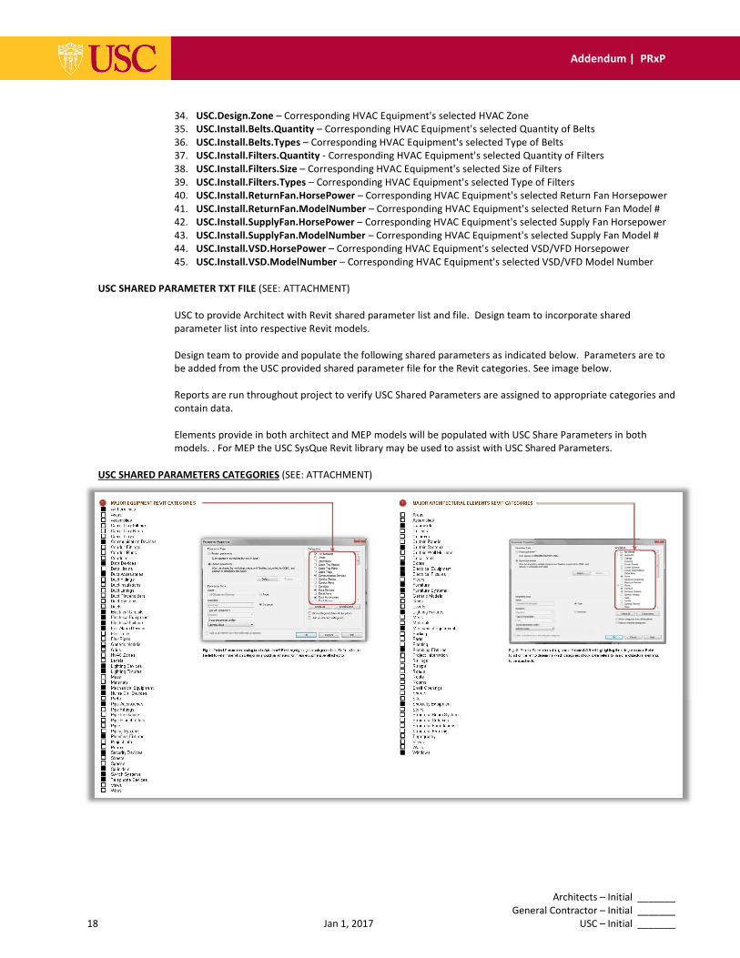
USC SHARED PARAMETER TXT FILE (SEE: ATTACHMENT)
USC to provide Architect with Revit shared parameter list and file. Design team to incorporate shared
parameter list into respective Revit models.
Design team to provide and populate the following shared parameters as indicated below. Parameters are to
be added from the USC provided shared parameter file for the Revit categories. See image below.
Reports are run throughout project to verify USC Shared Parameters are assigned to appropriate categories and
contain data.
Elements provide in both architect and MEP models will be populated with USC Share Parameters in both
models. . For MEP the USC SysQue Revit library may be used to assist with USC Shared Parameters.
USC SHARED PARAMETERS CATEGORIES (SEE: ATTACHMENT)
Architects – Initial _______
General Contractor – Initial _______
19 Jan 1, 2017 USC – Initial _______
Addendum | PRxP
SECTION K: MINIMUM MODELING MATRIX (M3)
The USACE M3 Minimum Modeling Matrix, in spreadsheet format, is a tool that shall be used by the entire
project team for non-Revit files to document and communicate the scope of modeled content of CADD files
within the Revit with linked AutoCAD deliverables, and help the project team organize the content by using
common classification systems such as Omniclass, Uniformat and Masterformat of CADD files. Additional
instructions are provided in the M3.
The Minimum Modeling Matrix (M3) can be found on the USC FMS Website.
SECTION L: ATTACHMENTS
Either insert the relevant information pertaining to the following within the applicable section of this document, or attach all documentation in this section:
1. LEVEL 1 PROCESS OVERVIEW MAP [SECTION E]
2. LEVEL 2 DETAILED Revit with linked AutoCAD USE PROCESS MAP(S) [SECTION E]
3. INFORMATION EXCHANGE REQUIREMENT WORKSHEET(S) – COBie [SECTION J]
4. MINIMUM MODELING MATRIX (M3) [SECTION K]
5. FILE NAMING STANDARD [SECTION I]
6. OTHER [AS APPLICABLE]

Architects – Initial _______
General Contractor – Initial _______
20 Jan 1, 2017 USC – Initial _______
Addendum | PRxP
SECTION M: EXECUTION PLAN SIGNATURE PAGE
By signing this form, the signatory certifies that he/she will follow the processes described in this Revit with linked
AutoCAD Execution Plan and provide all of the USC deliverables as scheduled.
DESIGN COMPANY PRINT NAME SIGNATURE DATE
INSTALLATION COMPANY PRINT NAME SIGNATURE DATE