university of florida thesis or …ufdcimages.uflib.ufl.edu/uf/e0/04/13/33/00001/lin_a.pdfoutline...
TRANSCRIPT
1
FABRICATION AND AEROELASTIC ANALYSIS OF SILICONE MEMBRANE MICRO AIR VEHICLE WINGS
By
ALBERT Y. LIN
A THESIS PRESENTED TO THE GRADUATE SCHOOL OF THE UNIVERSITY OF FLORIDA IN PARTIAL FULFILLMENT
OF THE REQUIREMENTS FOR THE DEGREE OF MASTER OF SCIENCE
UNIVERSITY OF FLORIDA
2009

2
© 2009 Albert Y. Lin

3
To Mom
4
ACKNOWLEDGMENTS
I would like to take this opportunity to thank everyone who has contributed to my
academics, research, and life throughout graduate school.
Yaakov Abudaram, for your camaraderie throughout the MAV Lab, wind tunnel, and
graduate school in general.
Mulugeta Haile
Vijay Jagdale, for teaching me the particulars of the VIC system.
, for your friendship and help with many lab experiments.
Kyuho Lee, for your passion and talent in aircraft design.
Dr. Bret Stanford, for teaching me the intricacies of the wind tunnel and your wealth of
academic knowledge. Thank you for taking time to answer my questions.
Pin Wu, for your conversations and generosity in sharing your laboratory.
My family, for your love and constant support.
Kim, Champ, Rhyley, and Lt. Dan, for your love and many happy memories.
I owe many thanks to Dr. Peter Ifju, for giving me so many opportunities to succeed. You
are a patient, enthusiastic, and talented teacher and I enjoyed my time working with you. Thank
you for everything that you have done for me.

5
TABLE OF CONTENTS page
ACKNOWLEDGMENTS ...................................................................................................... 4
LIST OF TABLES ................................................................................................................. 7
LIST OF FIGURES ............................................................................................................... 8
LIST OF ABBREVIATIONS ............................................................................................... 11
ABSTRACT ........................................................................................................................ 12
CHAPTER
1 INTRODUCTION ......................................................................................................... 13
Motivation .................................................................................................................... 13 Objectives ..................................................................................................................... 15 Outline.......................................................................................................................... 15
2 LITERATURE REVIEW............................................................................................... 16
3 EXPERIMENTAL DATA SYSTEMS ........................................................................... 20
Closed-Loop Wind Tunnel ............................................................................................. 20 Visual Image Correlation ............................................................................................... 21
4 SILICONE MEMBRANE FABRICATION .................................................................... 23
Baseline Airfoil ............................................................................................................. 23 Design Process .............................................................................................................. 23
Step One: Construct Composite Airframe ................................................................ 24 Step Two: Mix Silicone Compound ......................................................................... 25 Step Three: Apply Silicone Compound .................................................................... 26 Step Four: Apply Vacuum Pressure ......................................................................... 26 Step Five: VIC Preparation...................................................................................... 29
5 AEROELASTIC ANALYSIS ........................................................................................ 30
VIC Analysis ................................................................................................................ 30 Membrane Pre-Tension Validation .......................................................................... 30 Topology Optimization Design Comparison ............................................................. 35
Aerodynamic Data......................................................................................................... 41
6 RELATED CONCEPTS ................................................................................................ 46

6
7 CONCLUSION ............................................................................................................. 47
Conclusion .................................................................................................................... 47 Future Work .................................................................................................................. 47
APPENDIX
A EXPERIMENTAL OUT-OF-PLANE DISPLACEMENTS FOR BASELINE AND TOPOLOGY OPTIMIZED WING DESIGNS ................................................................ 49
B NUMERICAL OUT-OF-PLANE DISPLACEMENT MODELS FOR BASELINE AND TOPOLOGY OPTIMIZED WING DESIGNS, COURTESY OF STANFORD [4]............ 60
LIST OF REFERENCES ...................................................................................................... 66
BIOGRAPHICAL SKETCH ................................................................................................ 68
7
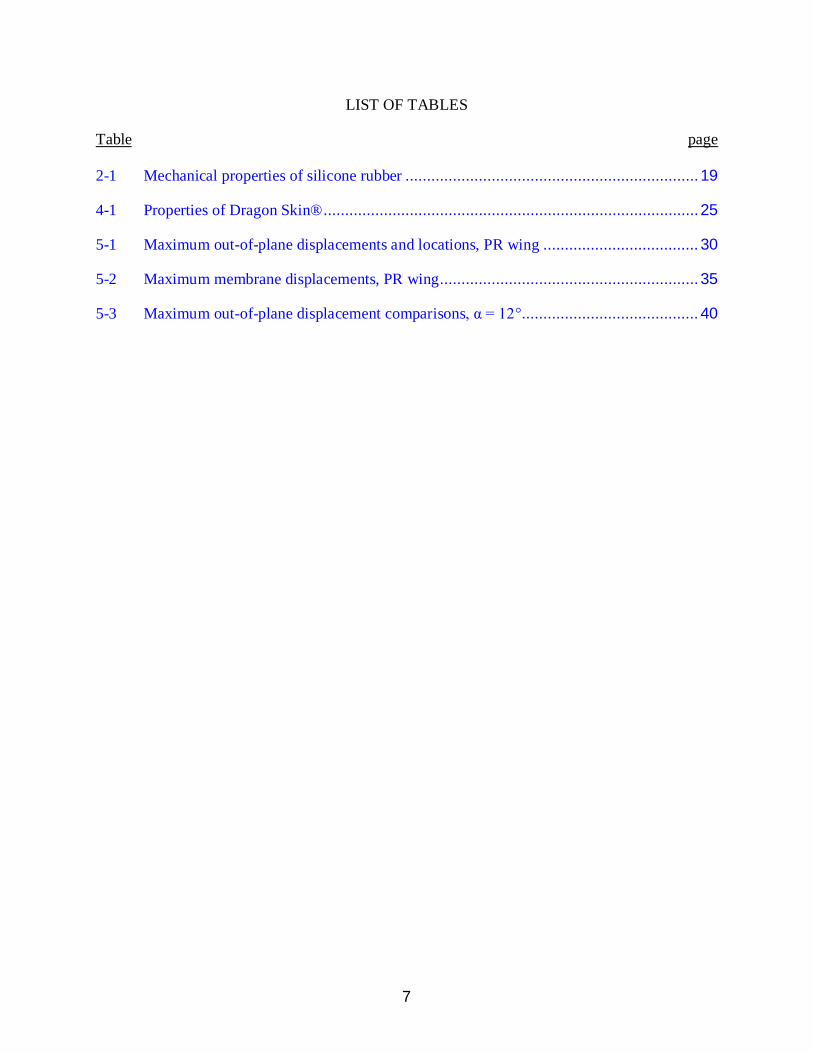
LIST OF TABLES
Table page 2-1 Mechanical properties of silicone rubber .................................................................... 19
4-1 Properties of Dragon Skin® ....................................................................................... 25
5-1 Maximum out-of-plane displacements and locations, PR wing .................................... 30
5-2 Maximum membrane displacements, PR wing ............................................................ 35
5-3 Maximum out-of-plane displacement comparisons, α = 12°......................................... 40

8
LIST OF FIGURES
Figure page 1-1 Erosion of latex at the bonding surfaces of BR wing after 60 days. .............................. 14
2-1 Cornell University bat wing design with nylon fabric affixed to carbon fiber skeletal fingers [8]. ................................................................................................................ 17
2-2 Cornell University bat wing design with thin silicone sheets glued to a steel wire skeletal frame [8]. ..................................................................................................... 18
3-1 Schematic of the experimental test section. ................................................................. 20
3-2 Random speckling pattern for VIC analysis. ............................................................... 21
3-3 VIC system arrangement above wind tunnel test section.............................................. 22
3-4 VIC cameras collect images through wind tunnel ceiling optical glass access. .............. 22
4-1 Types of wings constructed using the baseline airfoil. ................................................. 23
4-2 Cured carbon fiber TOP wing structure placed onto wing tool for membrane preparation. .............................................................................................................. 24
4-3 Pigmented liquid silicone compound applied to TOP wing. ......................................... 26
4-4 Wing mold containing composite frame and silicone compound under vacuum pressure. ................................................................................................................... 27
4-5 Creating a reverse imprint for the cavity mold using slow-curing epoxy. ...................... 28
4-6 Compression mold assembly for the baseline MAV wing. ........................................... 28
4-7 Compression mold assembly under 30 mm Hg vacuum pressure. ................................ 29
5-1 Experimental out-of-plane displacement contour, silicone membrane PR wing, α = 12° (refer Appendix A).............................................................................................. 31
5-2 Normalized out-of-plane displacement (w/c), silicone membrane PR wing, α = 12°. ..... 31
5-3 Out-of-plane displacement comparison of silicone membrane (top) and latex membrane PR (bottom), α = 12°. ............................................................................... 32
5-4 Normalized out-of-plane displacement comparison, PR membrane, α = 12°. ................ 33
5-5 Out-of-plane displacement comparison, regular (top) and viscosity-reduced (bottom) silicone membrane PR wing, α = 12°.......................................................................... 34
9
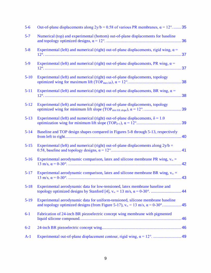
5-6 Out-of-plane displacements along 2y/b = 0.58 of various PR membranes, α = 12°. ....... 35
5-7 Numerical (top) and experimental (bottom) out-of-plane displacements for baseline and topology optimized designs, α = 12°. ................................................................... 36
5-8 Experimental (left) and numerical (right) out-of-plane displacements, rigid wing, α = 12°. .......................................................................................................................... 37
5-9 Experimental (left) and numerical (right) out-of-plane displacements, PR wing, α = 12°. .......................................................................................................................... 37
5-10 Experimental (left) and numerical (right) out-of-plane displacements, topology optimized wing for maximum lift (TOPmax lift), α = 12°. ............................................... 38
5-11 Experimental (left) and numerical (right) out-of-plane displacements, BR wing, α = 12°. .......................................................................................................................... 38
5-12 Experimental (left) and numerical (right) out-of-plane displacements, topology optimized wing for minimum lift slope (TOPmin lift slope), α = 12°. ................................. 39
5-13 Experimental (left) and numerical (right) out-of-plane displacements, δ = 1.0 optimization wing for minimum lift slope (TOPδ=1), α = 12°........................................ 39
5-14 Baseline and TOP design shapes compared in Figures 5-8 through 5-13, respectively from left to right........................................................................................................ 40
5-15 Experimental (left) and numerical (right) out-of-plane displacements along 2y/b = 0.58, baseline and topology designs, α = 12°............................................................... 41
5-16 Experimental aerodynamic comparison, latex and silicone membrane PR wing, v∞ = 13 m/s, α = 0-30°. ..................................................................................................... 42
5-17 Experimental aerodynamic comparison, latex and silicone membrane BR wing, v∞ = 13 m/s, α = 0-30°. ..................................................................................................... 43
5-18 Experimental aerodynamic data for low-tensioned, latex membrane baseline and topology optimized designs by Stanford [4], v∞ = 13 m/s, α = 0-30°. ........................... 44
5-19 Experimental aerodynamic data for uniform-tensioned, silicone membrane baseline and topology optimized designs (from Figure 5-17), v∞ = 13 m/s, α = 0-30°. ................ 45
6-1 Fabrication of 24-inch BR piezoelectric concept wing membrane with pigmented liquid silicone compound. .......................................................................................... 46
6-2 24-inch BR piezoelectric concept wing....................................................................... 46
A-1 Experimental out-of-plane displacement contour, rigid wing, α = 12°. ......................... 49

10
A-2 Experimental out-of-plane displacement contour, silicone membrane PR wing, α = 12°. .......................................................................................................................... 50
A-3 Experimental out-of-plane displacement contour, viscosity-reduced silicone membrane PR wing, α = 12°. ..................................................................................... 51
A-4 Experimental out-of-plane displacement contour, latex membrane PR wing, α = 12°. ... 52
A-5 Experimental out-of-plane displacement contour, silicone membrane BR wing, α = 12°. .......................................................................................................................... 53
A-6 Experimental out-of-plane displacement contour, silicone membrane TOP wing optimized for maximum lift (TOPmax lift), α = 12° (refer [4], Figure 7-10). .................... 54
A-7 Experimental out-of-plane displacement contour, silicone membrane TOP wing optimized for minimum lift slope (TOPmin lift slope), α = 12° (refer [4], Figure 7-10)........ 55
A-8 Experimental out-of-plane displacement contour, silicone membrane TOP wing optimized for minimum CL (TOPmin CL), α = 12° (refer [4], Figure 7-15)....................... 56
A-9 Experimental out-of-plane displacement contour, silicone membrane TOP wing optimized for minimum CD (TOPmin CD), α = 12° (refer [4], Figure 7-15). ..................... 57
A-10 Experimental out-of-plane displacement contour, silicone membrane TOP wing optimized for minimum Cm (TOPmin Cm), α = 12° (refer [4], Figure 7-15). .................... 58
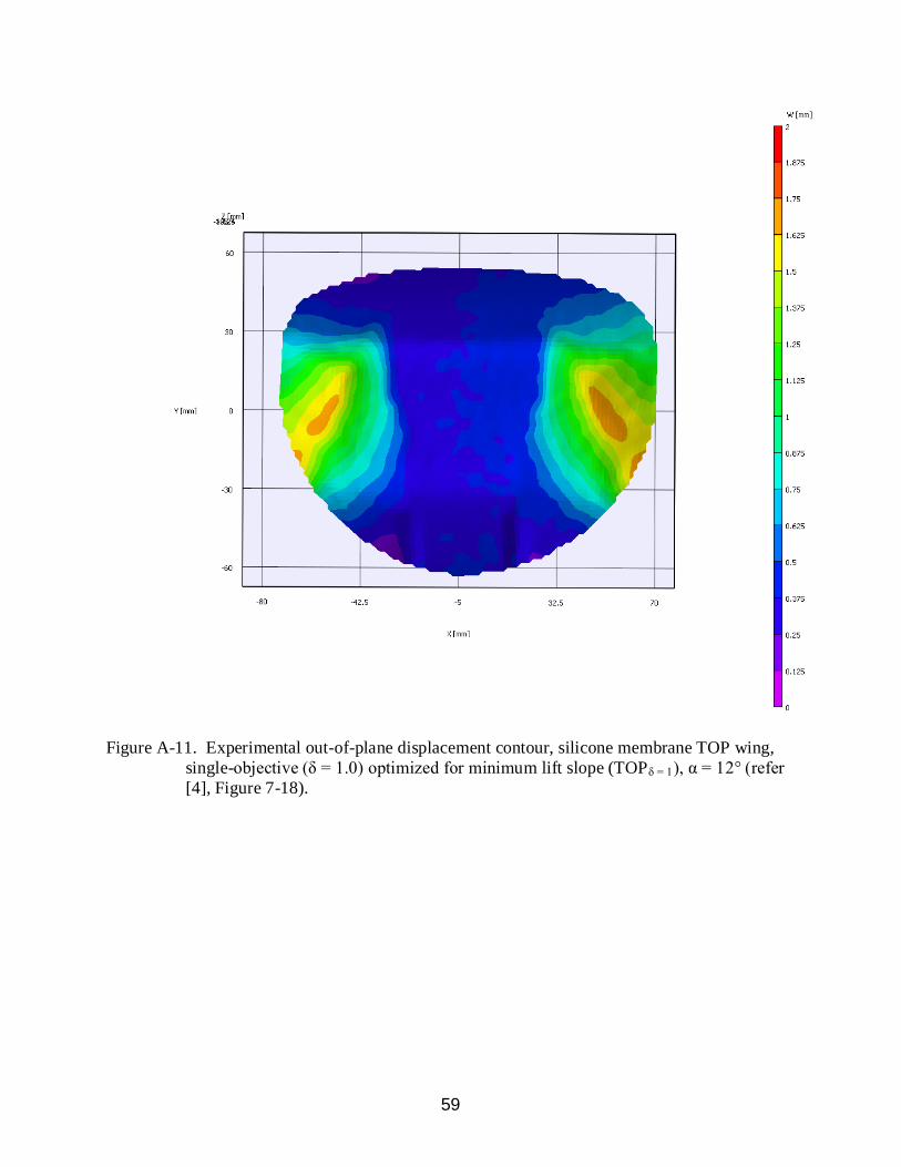
A-11 Experimental out-of-plane displacement contour, silicone membrane TOP wing, single-objective (δ = 1.0) optimized for minimum lift slope (TOPδ = 1), α = 12° (refer [4], Figure 7-18)........................................................................................................ 59
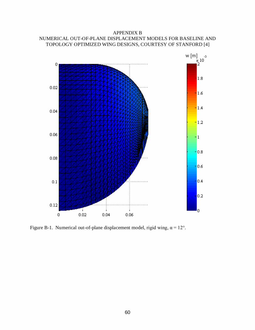
B-1 Numerical out-of-plane displacement model, rigid wing, α = 12°. ................................ 60
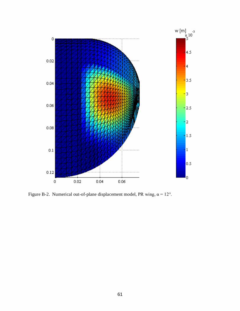
B-2 Numerical out-of-plane displacement model, PR wing, α = 12°. .................................. 61
B-3 Numerical out-of-plane displacement model, silicone membrane TOP wing optimized for maximum lift (TOPmax lift), α = 12° (refer [4], Figure 7-10). .................... 62
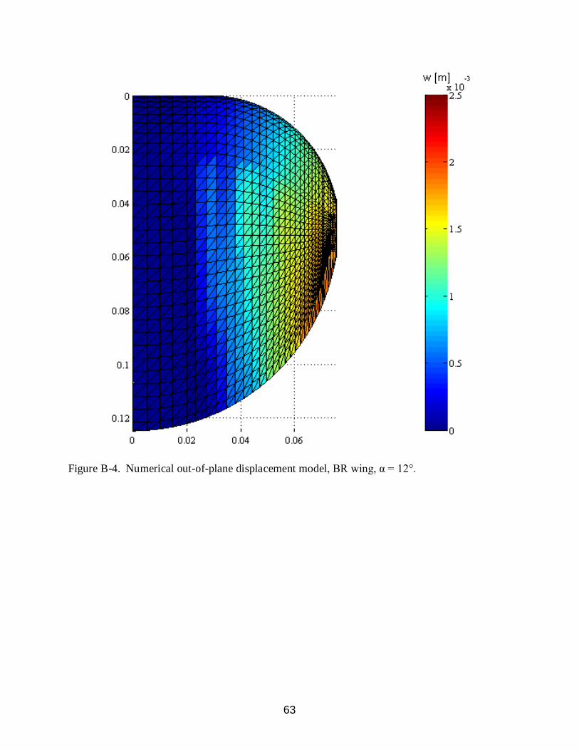
B-4 Numerical out-of-plane displacement model, BR wing, α = 12°. .................................. 63
B-5 Numerical out-of-plane displacement model, silicone membrane TOP wing optimized for minimum lift slope (TOPmin lift slope), α = 12° (refer [4], Figure 7-10)........ 64
B-6 Numerical out-of-plane displacement model, silicone membrane TOP wing, single-objective (δ = 1.0) optimized for minimum lift slope (TOPδ = 1), α = 12° (refer [4], Figure 7-18). ............................................................................................................. 65

11
LIST OF ABBREVIATIONS
Al aluminum
BR batten reinforced
C Celsius
cps centipoises
Hg mercury
hrs hours
in inch
KOH potassium hydroxide
lb pound
m meter(s)
MAV micro air vehicle
MEMS microelectromechanical systems
mm millimeter
N Newton
parylene-C poly-monochloro-para-xylylene
pli pounds per linear inch
PR perimeter reinforced
RTV room temperature vulcanizing
s second
Ti titanium
TOP topology optimized
UAV unmanned aerial vehicle
v∞
VIC visual image correlation
freestream velocity

12
Abstract of Thesis Presented to the Graduate School of the University of Florida in Partial Fulfillment of the
Requirements for the Degree of Master of Science
FABRICATION AND AEROELASTIC ANALYSIS OF SILICONE MEMBRANE MICRO AIR VEHICLE WINGS
By
Albert Y. Lin
December 2009
Chair: Peter Ifju Major: Aerospace Engineering
Flexible wing micro air vehicles (MAVs) have been developed at the University of Florida
to improve adverse flying conditions. Typically, such MAVs display low Reynolds numbers and
low aspect ratios. Current designs use elastic membranes bonded to a carbon fiber wing
structure. A variety of materials are functional as integrated membranes, such as latex and
polyester film. However, two design issues are presented with existing manufacturing
procedures. First, membrane materials lack robustness as they are vulnerable to rupture,
environmental conditions, and prolonged shelf-life. Second, uniform membrane pre-tension is
essentially unattainable by current procedures, causing disparities which can significantly alter
flight dynamics and create aeroelastic instabilities. A technique is developed which uses high
performance platinum-cure silicone rubber to fabricate wing membranes exhibiting uniform pre-
tension. Silicone rubber displays durability, high physical properties, and robustness in its
function as an integrated MAV membrane. Visual image correlation is performed to validate
silicone membrane displacements and pre-tensions of selected wing designs, as well as
comparisons to latex membrane counterparts. Experimental data, including aerodynamic
analysis, is further examined for aeroelastic topology optimized wings and compared with
numerical models.
13
CHAPTER 1 INTRODUCTION
Motivation
Numerous micro air vehicles (MAVs) designed at the University of Florida are based on
flexible wing structures, due to fixed-wing aerodynamic challenges resulting from low Reynolds
numbers (104-105) [1]. The basic design is composed of a composite laminate frame with an
affixed flexible membrane skin, which allows passive shape adaption [2]. Latex, mylar/polyester
film, ecorex, and nylon are typical materials used as membrane skins, with latex being the most
common. Perimeter reinforced (PR) wings have unconstrained interior membranes, bonded to a
rigid composite perimeter. PR membranes allow for camber adaptation to varying flight
conditions and wind gusts, translating load distributions on the wing which increases CL and
decreases Cmα [3]. Batten reinforced (BR) wings are designed with uni-directional strips of
carbon fiber parallel to the chord line, extending from the leading edge to an unconstrained
trailing edge. The battens are adhered to the membrane skin, much like a bat wing, to provide
flight load alleviation. Topology optimized (TOP) wings contain composite laminate
distributions positioned in specific locations on the membrane. These shapes and locations
correspond to specifically optimized aerodynamic functions [4].
Latex of minimal thickness (on the order of 0.12 mm) is typically used because of
billowing effects which aid in load distribution. After fabricating numerous latex membrane
wings, two significant design issues were observed. Latex membranes are not robust. They are
not durable and are susceptible to tearing, punctures, and erosion due to heat, UV, and chemical
agents. Figure 1-1 shows erosion of a latex membrane in contact with spray glue adhesive after
60 days. Degradation at the bonding points of the membrane inhibits flight performance
consistency and is detrimental to shelf life.

14
Figure 1-1. Erosion of latex at the bonding surfaces of BR wing after 60 days.
Second, uniform membrane per-tension is difficult to achieve and cannot be controlled by
existing manufacturing methods. Adaptive cambering membranes differing in pre-tension could
cause instabilities, greatly affecting flight dynamics of the aircraft. Consider a PR wing designed
for high lift, high drag which is manufactured with too much tension on one membrane. The
higher pre-tensioned membrane would require less drag, having more streamline shape. The
lower pre-tensioned membrane would have a larger deformation, thus higher drag. This scenario
could cause longitudinal and lateral instability of the wing, creating an adverse situation which
defeats the purpose of the intended design.
The purpose of this research is to develop a superior flexible membrane for incorporation
onto composite MAV wings. This requires a fabrication process to address the aforementioned
concerns, and silicone rubber will be introduced as the ideal material for this process.
15
Objectives
1. Develop a method to fabricate MAV wing membranes using platinum-cure silicone rubber.
2. Develop a method to create silicone membranes with uniform pre-tension.
3. Experimental validation of uniform membrane pre-tension.
4. Experimental comparison of latex and silicone membrane wings.
5. Experimental comparison and validation of topology optimized designs.
6. Fabricate conceptual wing designs using silicone rubber as the integration platform.
Outline
Chapter 2 is a literature review of bio-inspired designs, a silicone bat wing fabrication
process developed at Cornell University, and advantages of silicone rubber as a flexible MAV
membrane.
Chapter 3 classifies experimental apparatus and data analysis procedures. This involves
the visual image correlation system and closed-loop low-speed wind tunnel.
Chapter 4 details the silicone membrane fabrication process. A step-by-step method is
provided for co-curing room temperature vulcanizing silicone rubber to carbon fiber structures.
This chapter also provides visual image correlation preparation.
Chapter 5 analyzes experimental aeroelastic data. The PR design is used to validate pre-
tension uniformity of silicone membranes. A comparison is made between silicone membrane
wings and their latex membrane counterparts. Selected optimal topology wing designs are
evaluated and compared to numerical models.
Chapter 6 presents concepts related to bio-inspired wing designs and control surface
integration with silicone membranes.
16
CHAPTER 2 LITERATURE REVIEW
Currently, no manufacturing process exists for co-curing silicone rubber onto composite
MAV wings as functional flexible membranes. Growing research interests in bio-inspired,
skeletal-based designs have sparked intriguing innovations pursuing biological qualities and
morphing features. Pornsin-sirirak et al. [5] present a MEMS-based wing technology which uses
a titanium-alloy metal (Ti-6Al-4V) wingframe with a poly-monochloro-para-xylylene (parylene-
C) membrane. Target MEMS wings include bio-inspired designs such as beetles, dragonflies,
butterflies, and bats. Early efforts utilized silicon nitride pattern depositions and potassium
hydroxide (KOH) etching to create wingframes. However, silicon wingframes were too fragile
and abandoned in favor of the titanium-alloy metal.
Thin, compliant skin membranes unique to flying and gliding animals (bats, flying
squirrels, sugar gliders, etc.) exhibit maneuverability and agility unseen in other flying species of
comparable size [6]. Bat wing research has been conducted for piezoelectric actuation of joints
[7], various flight characteristics to develop optimal shapes [8], and aerodynamic effects of
membraned-wings [9]. Additionally, Waldman et al. [10] (Brown University) compares
membrane airfoil behavior under aerodynamic loading with in vivo measurements of bat wings
during flight. Bat membrane deformations are measured from recorded flight kinematics of a
Cynopterus brachyotis in a wind tunnel, in which downstroke wing areas are observed to
increase up to 100%.
Callahan and Garcia [11] discuss a bio-inspired bat wing fabrication method using a
skeleton structure with various membrane materials incorporated at Cornell University. Initially,
the skeleton was constructed with hollow carbon fiber rods, as it was light and strong enough to
withstand pressure loads of an attached membrane. Due to instability at the joints and weight
17
concerns with epoxy adhesives, the skeletal design was modified to steel rods with composite
fibers wrapped tightly around adjoining sections. Three membrane materials were tested: nylon
fabric, spandex fabric, and silicone sheets. Nylon and spandex fabrics were cut to desired wing
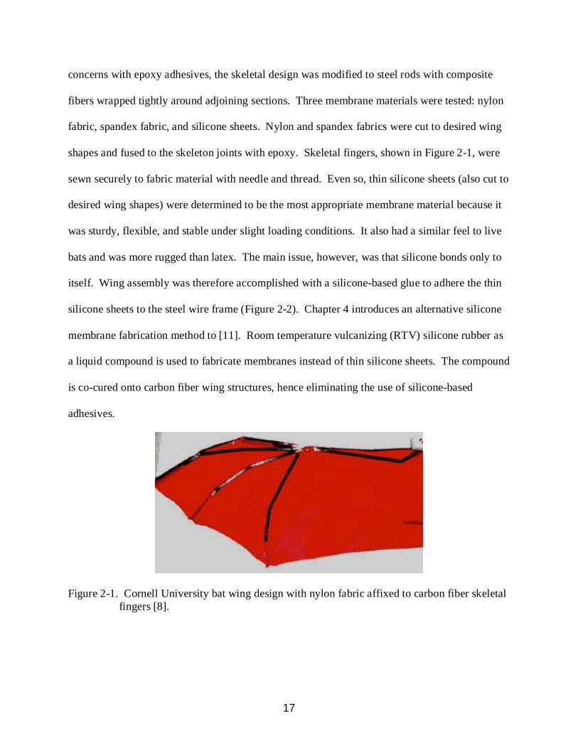
shapes and fused to the skeleton joints with epoxy. Skeletal fingers, shown in Figure 2-1, were
sewn securely to fabric material with needle and thread. Even so, thin silicone sheets (also cut to
desired wing shapes) were determined to be the most appropriate membrane material because it
was sturdy, flexible, and stable under slight loading conditions. It also had a similar feel to live
bats and was more rugged than latex. The main issue, however, was that silicone bonds only to
itself. Wing assembly was therefore accomplished with a silicone-based glue to adhere the thin
silicone sheets to the steel wire frame (Figure 2-2). Chapter 4 introduces an alternative silicone
membrane fabrication method to [11]. Room temperature vulcanizing (RTV) silicone rubber as
a liquid compound is used to fabricate membranes instead of thin silicone sheets. The compound
is co-cured onto carbon fiber wing structures, hence eliminating the use of silicone-based
adhesives.
Figure 2-1. Cornell University bat wing design with nylon fabric affixed to carbon fiber skeletal fingers [8].
18
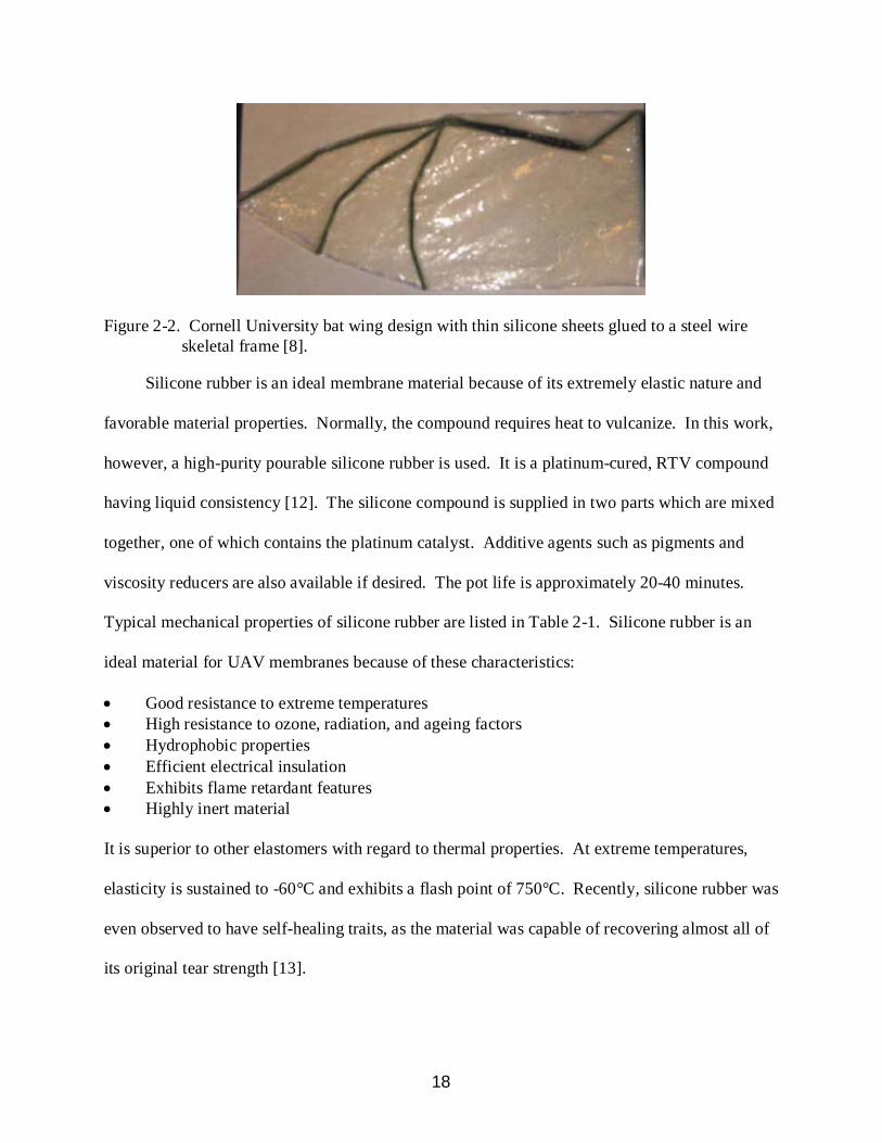
Figure 2-2. Cornell University bat wing design with thin silicone sheets glued to a steel wire skeletal frame [8].
Silicone rubber is an ideal membrane material because of its extremely elastic nature and
favorable material properties. Normally, the compound requires heat to vulcanize. In this work,
however, a high-purity pourable silicone rubber is used. It is a platinum-cured, RTV compound
having liquid consistency [12]. The silicone compound is supplied in two parts which are mixed
together, one of which contains the platinum catalyst. Additive agents such as pigments and
viscosity reducers are also available if desired. The pot life is approximately 20-40 minutes.
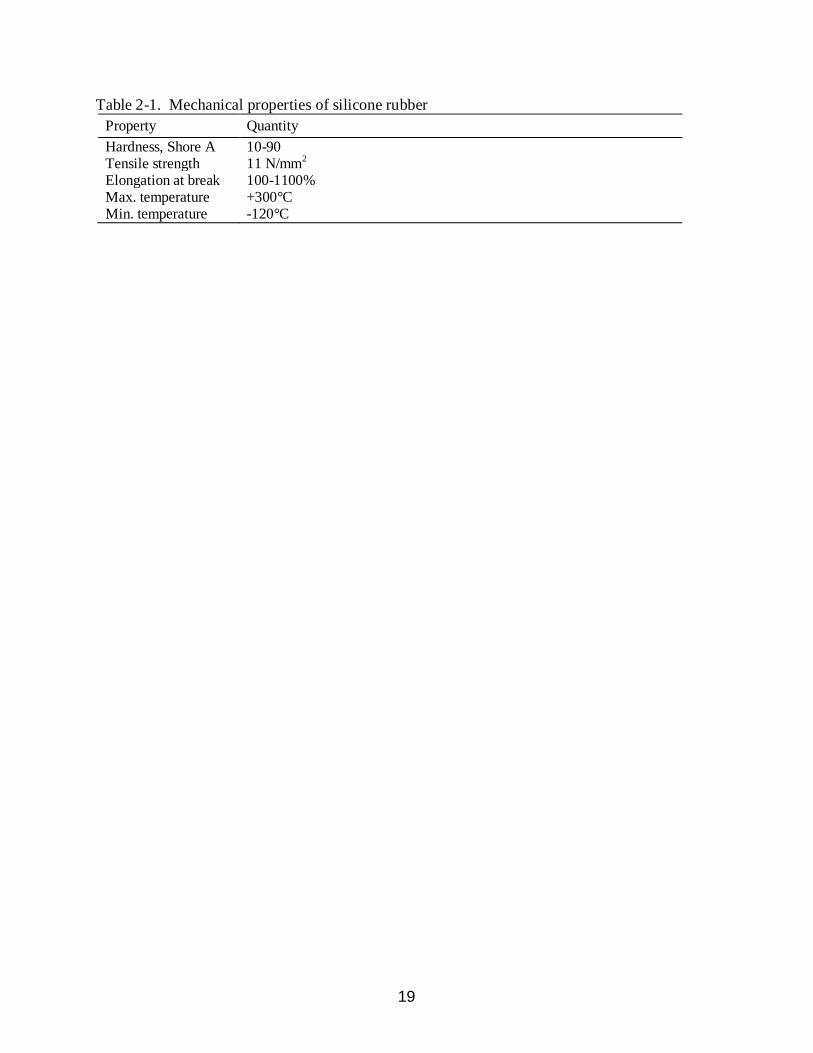
Typical mechanical properties of silicone rubber are listed in Table 2-1. Silicone rubber is an
ideal material for UAV membranes because of these characteristics:
• Good resistance to extreme temperatures • High resistance to ozone, radiation, and ageing factors • Hydrophobic properties • Efficient electrical insulation • Exhibits flame retardant features • Highly inert material It is superior to other elastomers with regard to thermal properties. At extreme temperatures,
elasticity is sustained to -60°C and exhibits a flash point of 750°C. Recently, silicone rubber was
even observed to have self-healing traits, as the material was capable of recovering almost all of
its original tear strength [13].
19
Table 2-1. Mechanical properties of silicone rubber Property Quantity Hardness, Shore A 10-90 Tensile strength 11 N/mm2 Elongation at break 100-1100% Max. temperature +300°C Min. temperature -120°C
20
CHAPTER 3 EXPERIMENTAL DATA SYSTEMS
Closed-Loop Wind Tunnel
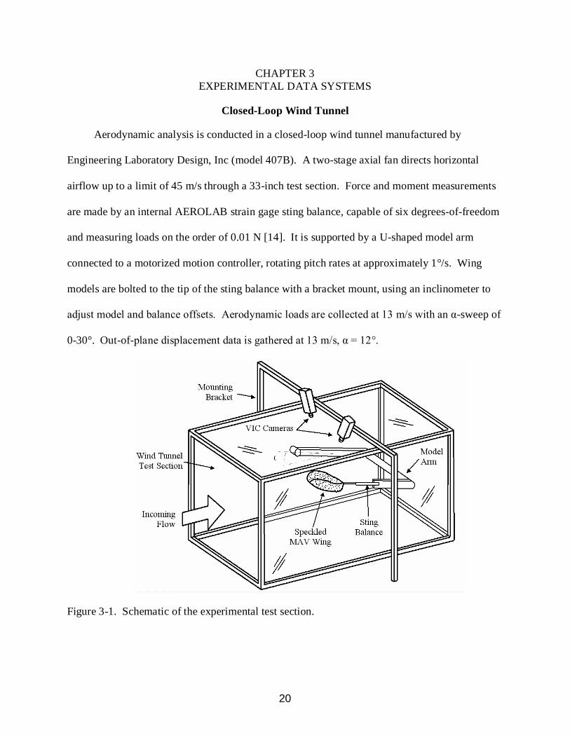
Aerodynamic analysis is conducted in a closed-loop wind tunnel manufactured by
Engineering Laboratory Design, Inc (model 407B). A two-stage axial fan directs horizontal
airflow up to a limit of 45 m/s through a 33-inch test section. Force and moment measurements
are made by an internal AEROLAB strain gage sting balance, capable of six degrees-of-freedom
and measuring loads on the order of 0.01 N [14]. It is supported by a U-shaped model arm
connected to a motorized motion controller, rotating pitch rates at approximately 1°/s. Wing
models are bolted to the tip of the sting balance with a bracket mount, using an inclinometer to
adjust model and balance offsets. Aerodynamic loads are collected at 13 m/s with an α-sweep of
0-30°. Out-of-plane displacement data is gathered at 13 m/s, α = 12°.
Figure 3-1. Schematic of the experimental test section.
21
Visual Image Correlation
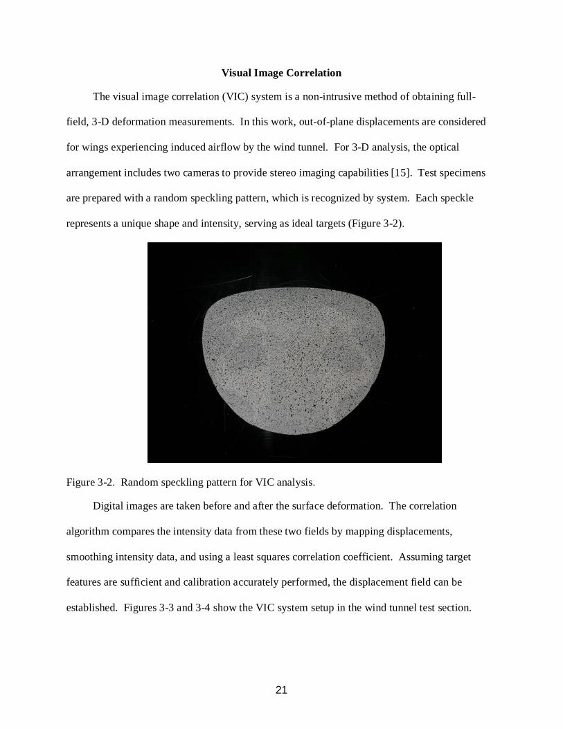
The visual image correlation (VIC) system is a non-intrusive method of obtaining full-
field, 3-D deformation measurements. In this work, out-of-plane displacements are considered
for wings experiencing induced airflow by the wind tunnel. For 3-D analysis, the optical
arrangement includes two cameras to provide stereo imaging capabilities [15]. Test specimens
are prepared with a random speckling pattern, which is recognized by system. Each speckle
represents a unique shape and intensity, serving as ideal targets (Figure 3-2).
Figure 3-2. Random speckling pattern for VIC analysis.
Digital images are taken before and after the surface deformation. The correlation
algorithm compares the intensity data from these two fields by mapping displacements,
smoothing intensity data, and using a least squares correlation coefficient. Assuming target
features are sufficient and calibration accurately performed, the displacement field can be
established. Figures 3-3 and 3-4 show the VIC system setup in the wind tunnel test section.

22
Figure 3-3. VIC system arrangement above wind tunnel test section.
Figure 3-4. VIC cameras collect images through wind tunnel ceiling optical glass access.
23
CHAPTER 4 SILICONE MEMBRANE FABRICATION
Baseline Airfoil
Baseline airfoil characteristics used in this work are:
• 152 mm wingspan • 124 mm root chord • 1.25 aspect ratio • 6.8% camber at the root (located at x/c = 0.22) • -1.4% reflex at the root (located at x/c = 0.86) • 7° dihedral (between 2y/b = 0.4 and the wingtip) • 7° geometric twist (nose up) at the wingtips
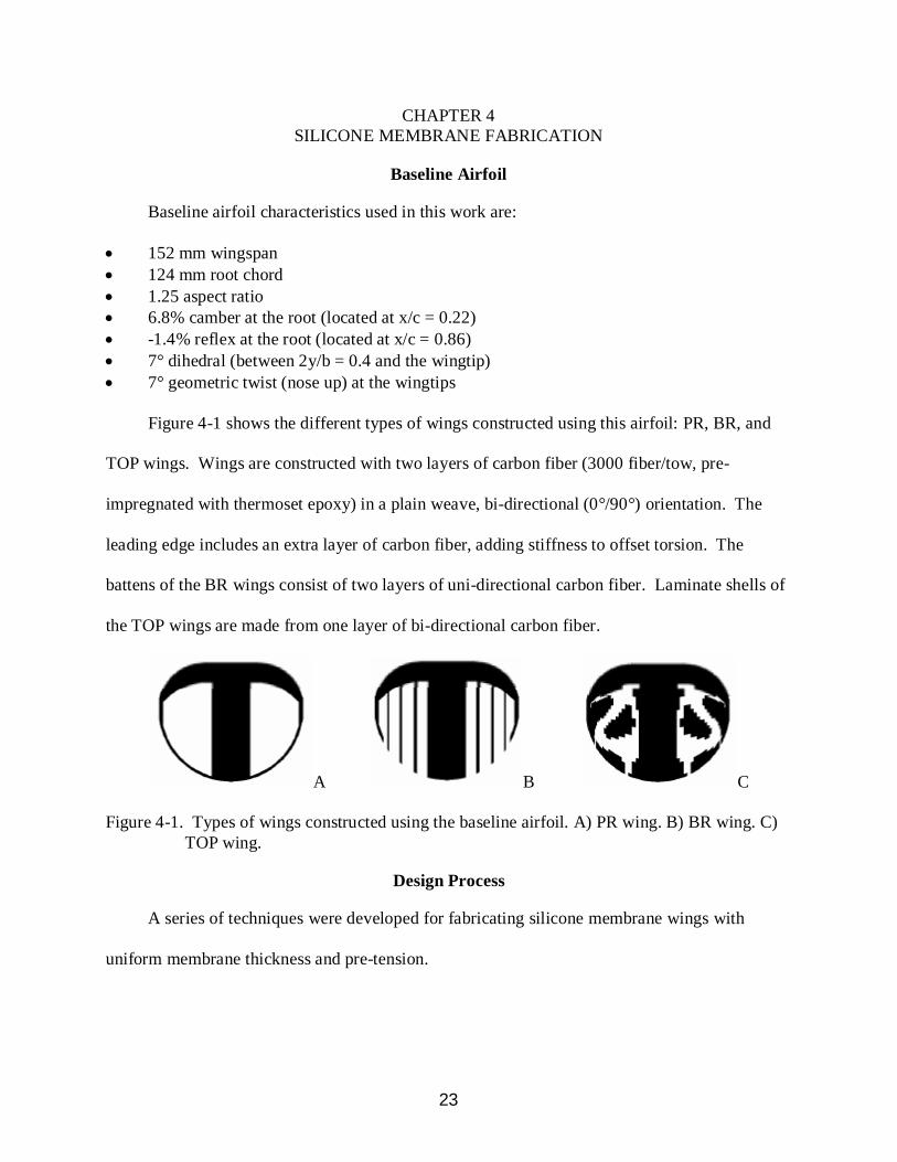
Figure 4-1 shows the different types of wings constructed using this airfoil: PR, BR, and
TOP wings. Wings are constructed with two layers of carbon fiber (3000 fiber/tow, pre-
impregnated with thermoset epoxy) in a plain weave, bi-directional (0°/90°) orientation. The
leading edge includes an extra layer of carbon fiber, adding stiffness to offset torsion. The
battens of the BR wings consist of two layers of uni-directional carbon fiber. Laminate shells of
the TOP wings are made from one layer of bi-directional carbon fiber.
A B C
Figure 4-1. Types of wings constructed using the baseline airfoil. A) PR wing. B) BR wing. C) TOP wing.
Design Process
A series of techniques were developed for fabricating silicone membrane wings with
uniform membrane thickness and pre-tension.
24
Step One: Construct Composite Airframe
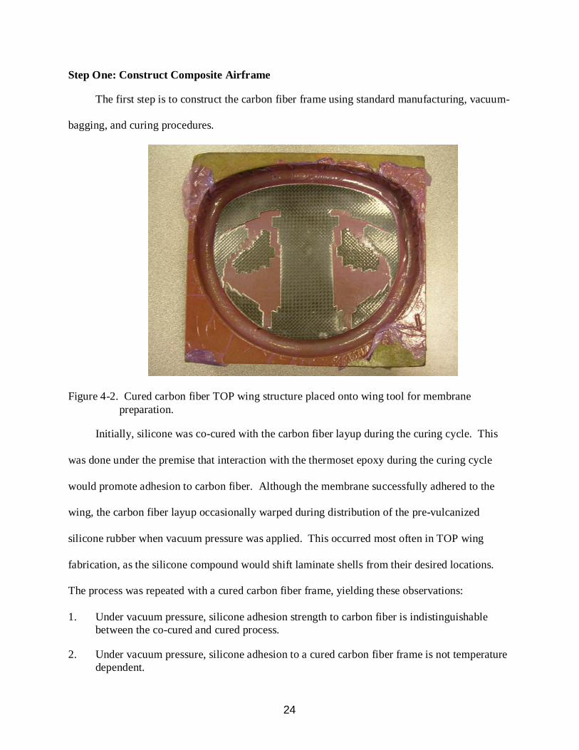
The first step is to construct the carbon fiber frame using standard manufacturing, vacuum-
bagging, and curing procedures.
Figure 4-2. Cured carbon fiber TOP wing structure placed onto wing tool for membrane preparation.
Initially, silicone was co-cured with the carbon fiber layup during the curing cycle. This
was done under the premise that interaction with the thermoset epoxy during the curing cycle
would promote adhesion to carbon fiber. Although the membrane successfully adhered to the
wing, the carbon fiber layup occasionally warped during distribution of the pre-vulcanized
silicone rubber when vacuum pressure was applied. This occurred most often in TOP wing
fabrication, as the silicone compound would shift laminate shells from their desired locations.
The process was repeated with a cured carbon fiber frame, yielding these observations:
1. Under vacuum pressure, silicone adhesion strength to carbon fiber is indistinguishable between the co-cured and cured process.
2. Under vacuum pressure, silicone adhesion to a cured carbon fiber frame is not temperature dependent.

25
3. Both methods are successful, but it is much easier to fabricate silicone membrane wings using a cured carbon fiber frame.
An increase in temperature accelerated the vulcanization rate of the silicone compound, but
did not affect the bonding strength to carbon fiber. From a manufacturing standpoint, the best
approach is to cure the carbon fiber structure first. It eliminates structural warping and prevents
laminate shifting of TOP wings. However, future work is suggested to measure the adhesion
strength between RTV and temperature-accelerated silicone.
Step Two: Mix Silicone Compound
The next step is to mix the silicone compound. Once the components are mixed, the liquid
silicone is centrifuged (approximately 3 minutes) to eliminate air bubbles from the solution. The
silicone rubber used is called Dragon Skin®, manufactured by Smooth-On, Inc. It is a two-
component, platinum curing silicone elastomer composed of polyorganosiloxanes, amorphous
silca, and platinum-siloxane complex. This material is extremely flexible and yields a high tear
strength.
Table 4-1. Properties of Dragon Skin® Property Quantity Elongation at break 1000% Mixed viscosity 23000 cps Shore A hardness 10 Tear strength 102 pli Weight 25.8 in3/lb Demold time 5 hrs
Silicone additives may be applied to assist with membrane thickness and enhance VIC
analysis. A thinning agent (SilcThin®) was used to reduce the viscosity of the mixture to
improve workability and prolong pot life. However, this additive does reduce material strength.
The maximum amount allowed is 7.5% of the total mixture weight.

26
Step Three: Apply Silicone Compound
Once air bubbles are removed, the silicone is applied to the wing tool. For releasing
purposes, a layer of Teflon film is affixed to the wing tool with a thin coat of spray glue. It is
essential to keep the wing tool smooth and free of defects as this surface directly translates to the
surface of the membrane. At this point, the carbon fiber frame is placed onto the wing tool and
silicone is poured onto the proper locations.
Figure 4-3. Pigmented liquid silicone compound applied to TOP wing.
Step Four: Apply Vacuum Pressure
The mold is placed in a vacuum bag under a suction pressure of 30 mm Hg [16]. Initially,
the silicone was smoothed out by hand and rubber rollers through the vacuum bag (Figure 4-4).
This method created two major setbacks. First, warping and shifting of the wing structure
(expressed in Step One) occurred, primarily in un-cured carbon fiber frames and TOP wings.
Second, the cured silicone membrane did not have consistent thickness. The thickness disparity
27
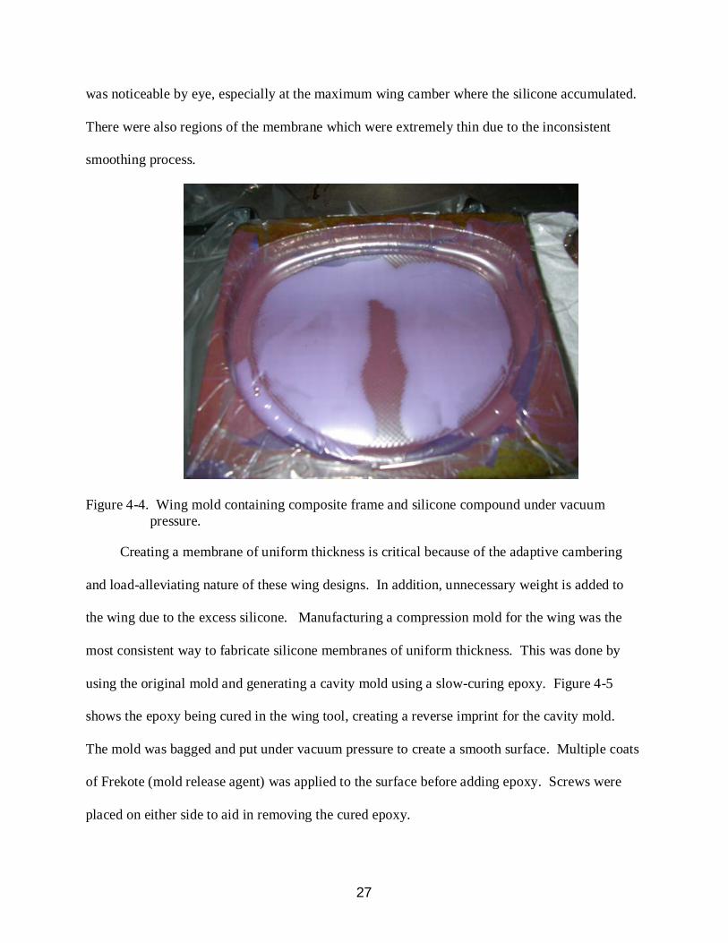
was noticeable by eye, especially at the maximum wing camber where the silicone accumulated.
There were also regions of the membrane which were extremely thin due to the inconsistent
smoothing process.
Figure 4-4. Wing mold containing composite frame and silicone compound under vacuum pressure.
Creating a membrane of uniform thickness is critical because of the adaptive cambering
and load-alleviating nature of these wing designs. In addition, unnecessary weight is added to
the wing due to the excess silicone. Manufacturing a compression mold for the wing was the
most consistent way to fabricate silicone membranes of uniform thickness. This was done by
using the original mold and generating a cavity mold using a slow-curing epoxy. Figure 4-5
shows the epoxy being cured in the wing tool, creating a reverse imprint for the cavity mold.
The mold was bagged and put under vacuum pressure to create a smooth surface. Multiple coats
of Frekote (mold release agent) was applied to the surface before adding epoxy. Screws were
placed on either side to aid in removing the cured epoxy.
28
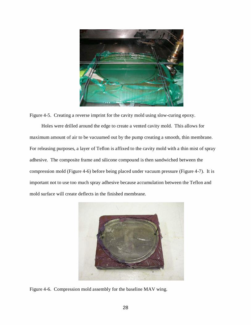
Figure 4-5. Creating a reverse imprint for the cavity mold using slow-curing epoxy.
Holes were drilled around the edge to create a vented cavity mold. This allows for
maximum amount of air to be vacuumed out by the pump creating a smooth, thin membrane.
For releasing purposes, a layer of Teflon is affixed to the cavity mold with a thin mist of spray
adhesive. The composite frame and silicone compound is then sandwiched between the
compression mold (Figure 4-6) before being placed under vacuum pressure (Figure 4-7). It is
important not to use too much spray adhesive because accumulation between the Teflon and
mold surface will create deflects in the finished membrane.
Figure 4-6. Compression mold assembly for the baseline MAV wing.
29
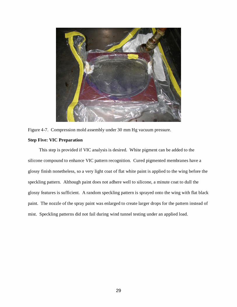
Figure 4-7. Compression mold assembly under 30 mm Hg vacuum pressure.
Step Five: VIC Preparation
This step is provided if VIC analysis is desired. White pigment can be added to the
silicone compound to enhance VIC pattern recognition. Cured pigmented membranes have a
glossy finish nonetheless, so a very light coat of flat white paint is applied to the wing before the
speckling pattern. Although paint does not adhere well to silicone, a minute coat to dull the
glossy features is sufficient. A random speckling pattern is sprayed onto the wing with flat black
paint. The nozzle of the spray paint was enlarged to create larger drops for the pattern instead of
mist. Speckling patterns did not fail during wind tunnel testing under an applied load.

30
CHAPTER 5 AEROELASTIC ANALYSIS
VIC Analysis
VIC analysis was conducted on baseline and topology optimized wing designs in the wind
tunnel at v∞
• Validate uniform pre-tension of silicone membranes
= 13 m/s and α = 12°. Objectives are to:
• Compare latex and silicone membrane designs • Observe the effects of reduced-viscosity silicone • Compare experimental results with numerical models of topology optimized designs
Membrane Pre-Tension Validation
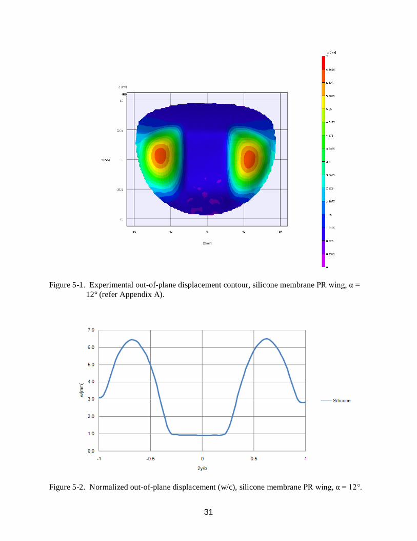
The PR wing was used as the baseline for validating uniform membrane tension. Figure 5-
1 shows the symmetry of out-of-plane displacements across both membranes. Inflation occurs at
the consistent locations along spanwise sections. Maximum out-of-plane displacement is 6.45
mm, measured at 2y/b = -0.70 for the left membrane and 6.48 mm, measured at 2y/b = 0.68 for
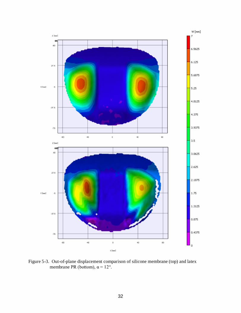
the right membrane (Figure 5-2). Figure 5-3 compares the silicone membrane PR wing to its
latex membrane counterpart. The same PR wingframe was used to construct both wings. Latex
membranes were adhered with low-tension to promote maximum inflation for this comparison.
Also, uniform pre-tension was attempted when adhering the latex membranes. Although
maximum out-of-plane displacements do not differ by much (Figure 5-4), Figure 5-3 is evidence
that the latex membrane vastly underachieves in its attempt at membrane pre-tension uniformity.
The contour also reveals inconsistent and decreased inflation surface area for the latex
membranes. Maximum out-of-plane displacements are shown in Table 5-1.
Table 5-1. Maximum out-of-plane displacements and locations, PR wing Membrane w [mm] Location (2y/b) Silicone, left 6.45 -0.70 Silicone, right 6.48 0.68 Latex, left 6.43 -0.58 Latex, right 5.76 0.68
31
Figure 5-1. Experimental out-of-plane displacement contour, silicone membrane PR wing, α = 12° (refer Appendix A).
Figure 5-2. Normalized out-of-plane displacement (w/c), silicone membrane PR wing, α = 12°.
32
Figure 5-3. Out-of-plane displacement comparison of silicone membrane (top) and latex membrane PR (bottom), α = 12°.
33
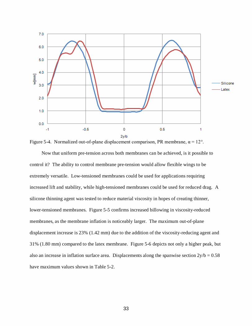
Figure 5-4. Normalized out-of-plane displacement comparison, PR membrane, α = 12°.
Now that uniform pre-tension across both membranes can be achieved, is it possible to
control it? The ability to control membrane pre-tension would allow flexible wings to be
extremely versatile. Low-tensioned membranes could be used for applications requiring
increased lift and stability, while high-tensioned membranes could be used for reduced drag. A
silicone thinning agent was tested to reduce material viscosity in hopes of creating thinner,
lower-tensioned membranes. Figure 5-5 confirms increased billowing in viscosity-reduced
membranes, as the membrane inflation is noticeably larger. The maximum out-of-plane
displacement increase is 23% (1.42 mm) due to the addition of the viscosity-reducing agent and
31% (1.80 mm) compared to the latex membrane. Figure 5-6 depicts not only a higher peak, but
also an increase in inflation surface area. Displacements along the spanwise section 2y/b = 0.58
have maximum values shown in Table 5-2.

34
Figure 5-5. Out-of-plane displacement comparison, regular (top) and viscosity-reduced (bottom) silicone membrane PR wing, α = 12°.

35
Figure 5-6. Out-of-plane displacements along 2y/b = 0.58 of various PR membranes, α = 12°.
The silicone thinning agent does reduce material strength, which could cause the increased
inflation instead of a reduced membrane pre-tension. A weaker membrane would be expected to
inflate more under the same loads, and the distinction could not be clarified through these
experiments. Future work is recommended to determine the effect of viscosity-reducing agents
on material strength. A thermal test, as well as a pressure test, is recommended to determine if
pre-tension can be controlled as a function of curing temperature, or vacuum pressure, or both.
Table 5-2. Maximum membrane displacements, PR wing Membrane w [mm] Location (x/c) Latex 5.74 0.47 Silicone 6.12 0.50 Silicone Reduced Viscosity 7.54 0.50
Topology Optimization Design Comparison
Stanford [4] formulates the computational framework for aeroelastic topology optimization
of MAVs. Optimization of laminate topologies and locations is a function of flight condition,

36
grid density, initial guess, and design metric. Figure 5-7 presents baseline (A, B, D) and
topology optimized (C, E) wing designs. Wing C is a lift-augmenting design optimized for
maximum lift. Wing E is a lift-alleviating design optimized for minimum lift slope. The top row
in Figure 5-7 represents deformations predicted by Stanford [4]. The bottom row depicts
experimental out-of-plane deformation results of the same wing designs, fabricated with silicone
membranes. Detailed experimental contours are listed in Appendix A. Appendix B lists
numerical models gathered by Stanford [4].
Figure 5-7. Numerical (top) and experimental (bottom) out-of-plane displacements for baseline and topology optimized designs, α = 12°.
Figures 5-8 thru 5-13 illustrate comparisons between experimental results and numerical
models generated by Stanford [4]. Comparisons are made between baseline and topology
optimized designs for different cases. Figures show out-of-plane displacements contours in
meters, with experimental results on the left half and its corresponding numerical model on the
right half. Since membrane pre-tension parameters were not equal for the two models, a
difference in maximum displacement values is expected (Table 5-3). It is more significant to
note the shape similarities displayed in the following comparisons.

37
Figure 5-8. Experimental (left) and numerical (right) out-of-plane displacements, rigid wing, α = 12°.
Figure 5-9. Experimental (left) and numerical (right) out-of-plane displacements, PR wing, α = 12°.

38
Figure 5-10. Experimental (left) and numerical (right) out-of-plane displacements, topology optimized wing for maximum lift (TOPmax lift), α = 12°.
Figure 5-11. Experimental (left) and numerical (right) out-of-plane displacements, BR wing, α = 12°.
39
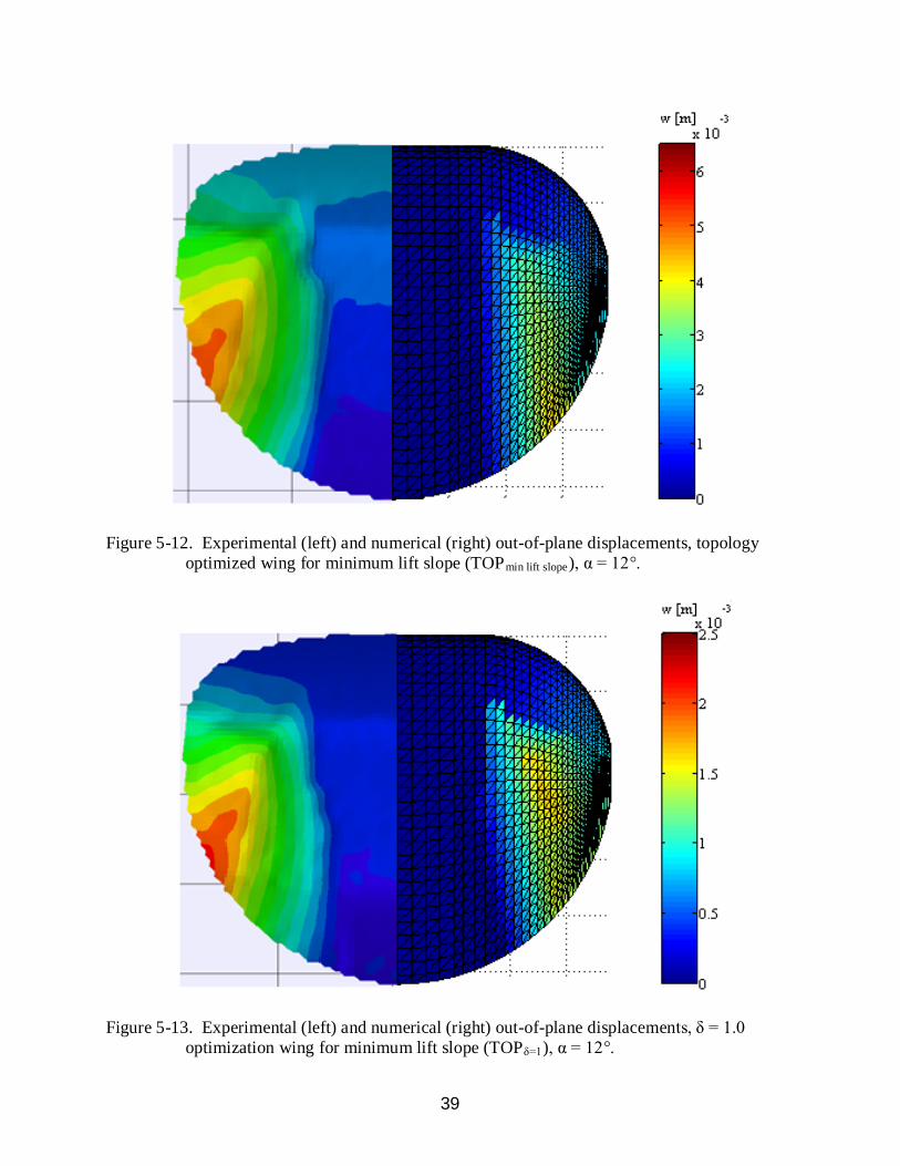
Figure 5-12. Experimental (left) and numerical (right) out-of-plane displacements, topology optimized wing for minimum lift slope (TOPmin lift slope), α = 12°.
Figure 5-13. Experimental (left) and numerical (right) out-of-plane displacements, δ = 1.0 optimization wing for minimum lift slope (TOPδ=1), α = 12°.
40
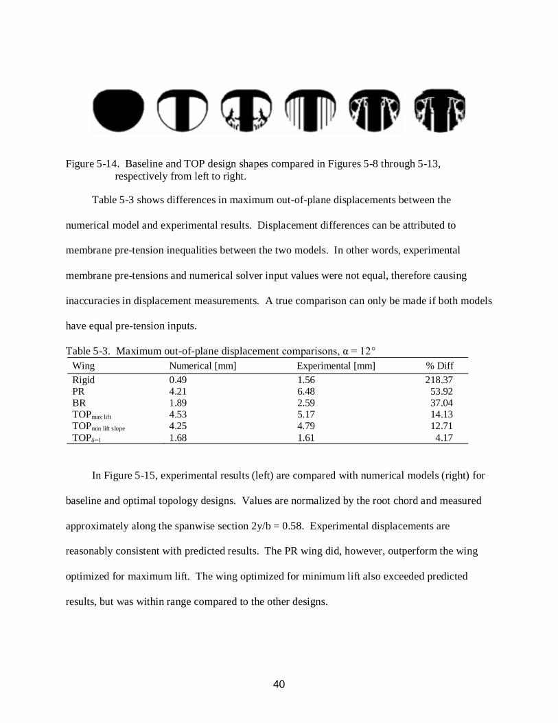
Figure 5-14. Baseline and TOP design shapes compared in Figures 5-8 through 5-13,
respectively from left to right.
Table 5-3 shows differences in maximum out-of-plane displacements between the
numerical model and experimental results. Displacement differences can be attributed to
membrane pre-tension inequalities between the two models. In other words, experimental
membrane pre-tensions and numerical solver input values were not equal, therefore causing
inaccuracies in displacement measurements. A true comparison can only be made if both models
have equal pre-tension inputs.
Table 5-3. Maximum out-of-plane displacement comparisons, α = 12° Wing Numerical [mm] Experimental [mm] % Diff Rigid 0.49 1.56 218.37 PR 4.21 6.48 53.92 BR 1.89 2.59 37.04 TOPmax lift 4.53 5.17 14.13 TOPmin lift slope 4.25 4.79 12.71 TOPδ=1 1.68 1.61 4.17
In Figure 5-15, experimental results (left) are compared with numerical models (right) for
baseline and optimal topology designs. Values are normalized by the root chord and measured
approximately along the spanwise section 2y/b = 0.58. Experimental displacements are
reasonably consistent with predicted results. The PR wing did, however, outperform the wing
optimized for maximum lift. The wing optimized for minimum lift also exceeded predicted
results, but was within range compared to the other designs.

41
Figure 5-15. Experimental (left) and numerical (right) out-of-plane displacements along 2y/b = 0.58, baseline and topology designs, α = 12°.
Aerodynamic Results
All wind tunnel tests were conducted at α = 12° and v∞
= 13 m/s. Experimental
aerodynamic data was collected for two comparative studies. First, the performance of latex
membrane and silicone membrane designs was measured using PR and BR wings as baselines.
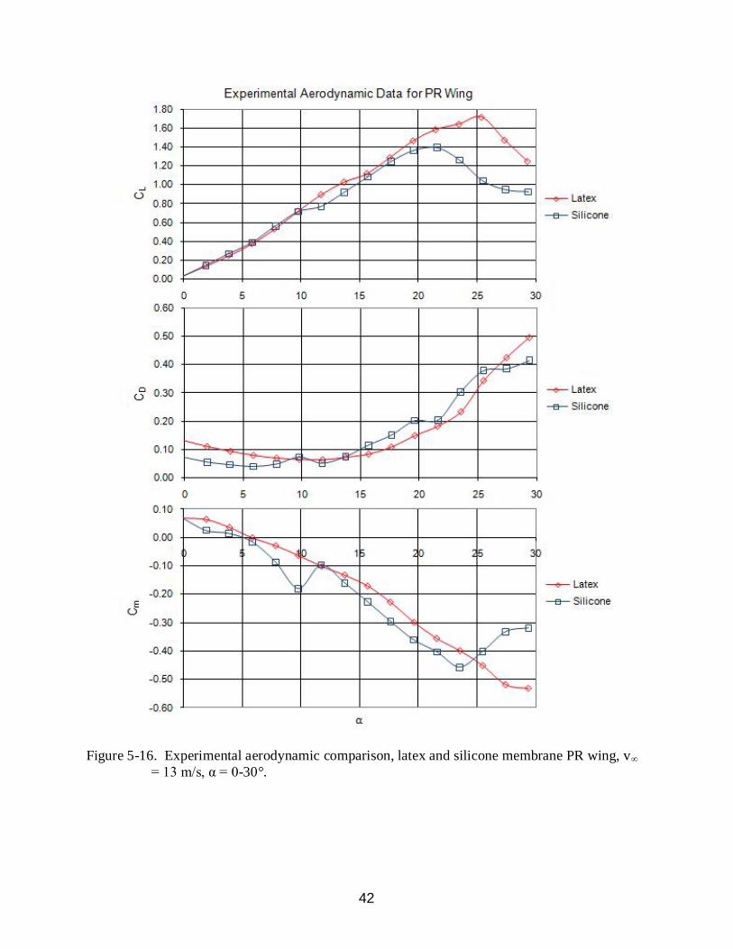
Select aerodynamic coefficients for the PR wing are given in Figure 5-16. BR results are shown
in Figure 5-17. The silicone membrane PR wing displayed a shallower lift slope and steeper
pitching moment slope. It also had less drag at smaller angles of attack (less than 10°), but higher
drag as α increased past 15°. Stall occurred at α = 22° for the silicone membrane PR wing while
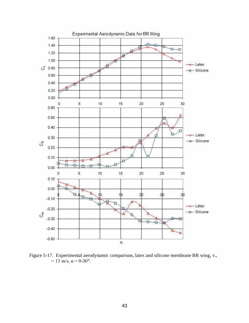
the latex membrane PR wing stalled at α = 25°. Lift data for the BR wing was fairly similar.
However, the silicone design outperformed the latex design according to drag and pitching
moment.
42
Figure 5-16. Experimental aerodynamic comparison, latex and silicone membrane PR wing, v∞
= 13 m/s, α = 0-30°.
43
Figure 5-17. Experimental aerodynamic comparison, latex and silicone membrane BR wing, v∞
= 13 m/s, α = 0-30°.
44
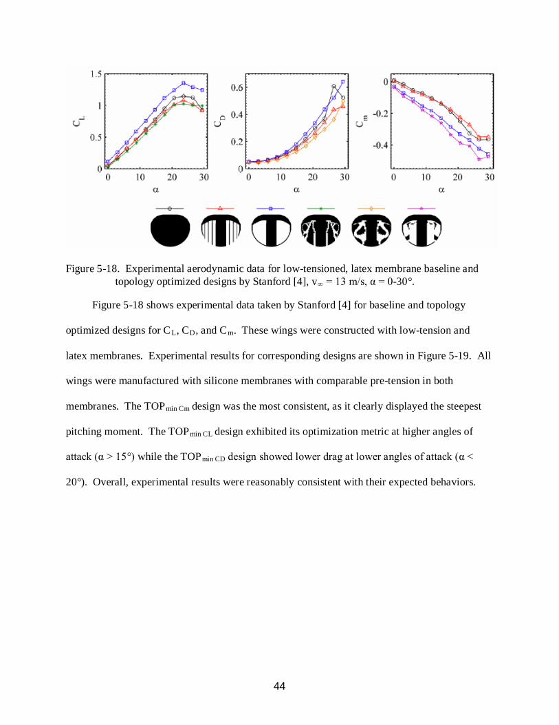
Figure 5-18. Experimental aerodynamic data for low-tensioned, latex membrane baseline and topology optimized designs by Stanford [4], v∞
Figure 5-18 shows experimental data taken by Stanford
= 13 m/s, α = 0-30°.
[4] for baseline and topology
optimized designs for CL, CD, and Cm. These wings were constructed with low-tension and
latex membranes. Experimental results for corresponding designs are shown in Figure 5-19. All
wings were manufactured with silicone membranes with comparable pre-tension in both
membranes. The TOPmin Cm design was the most consistent, as it clearly displayed the steepest
pitching moment. The TOPmin CL design exhibited its optimization metric at higher angles of
attack (α > 15°) while the TOPmin CD
design showed lower drag at lower angles of attack (α <
20°). Overall, experimental results were reasonably consistent with their expected behaviors.

45
Figure 5-19. Experimental aerodynamic data for uniform-tensioned, silicone membrane baseline and topology optimized designs (from Figure 5-17), v∞ = 13 m/s, α = 0-30°.
46
CHAPTER 6 RELATED CONCEPTS
Recently, there is heightened interest in developing bio-inspired wings. Much effort has
been dedicated to the study of natural flyers in hopes of mimicking beneficial flight
characteristics. Silicone membrane manufacturing techniques developed in this work may be
helpful in creating designs along the bio-inspiration front, including bat wing designs as
expressed in Chapter 2. Composite skeletons could be co-cured with silicone membrane designs
to develop very robust and realistic MAVs.
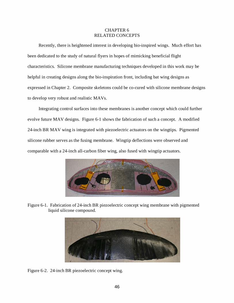
Integrating control surfaces into these membranes is another concept which could further
evolve future MAV designs. Figure 6-1 shows the fabrication of such a concept. A modified
24-inch BR MAV wing is integrated with piezoelectric actuators on the wingtips. Pigmented
silicone rubber serves as the fusing membrane. Wingtip deflections were observed and
comparable with a 24-inch all-carbon fiber wing, also fused with wingtip actuators.
Figure 6-1. Fabrication of 24-inch BR piezoelectric concept wing membrane with pigmented liquid silicone compound.
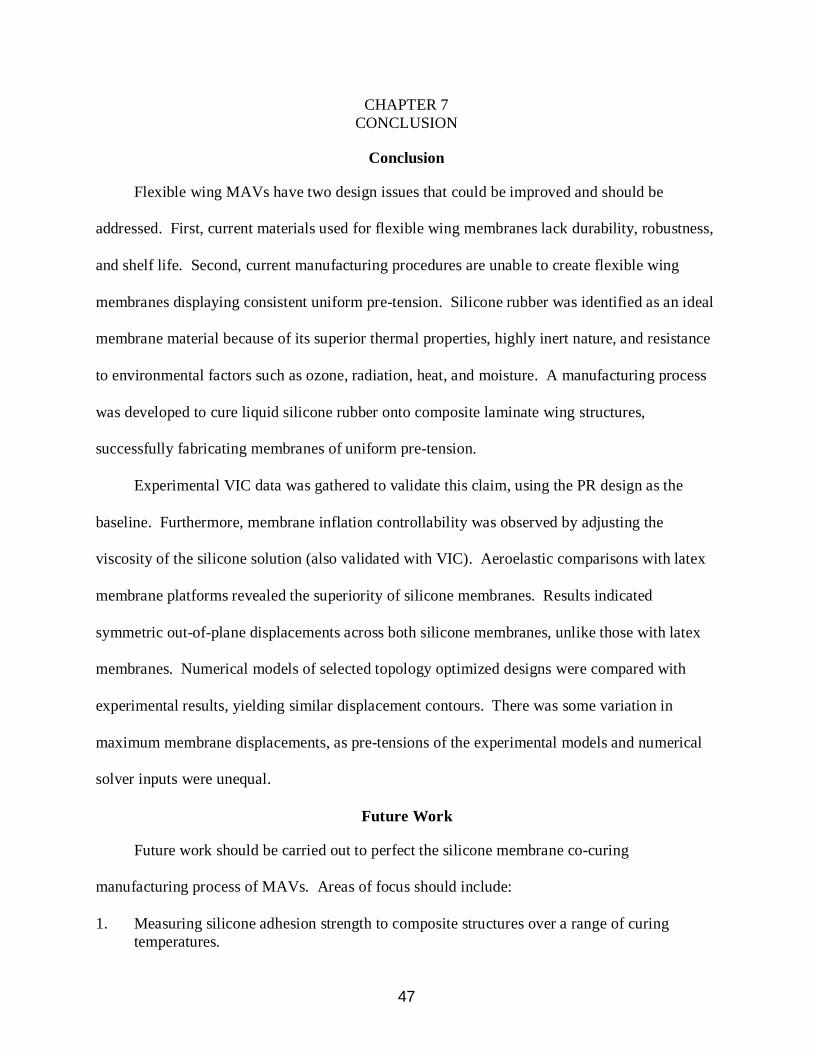
Figure 6-2. 24-inch BR piezoelectric concept wing.
47
CHAPTER 7 CONCLUSION
Conclusion
Flexible wing MAVs have two design issues that could be improved and should be
addressed. First, current materials used for flexible wing membranes lack durability, robustness,
and shelf life. Second, current manufacturing procedures are unable to create flexible wing
membranes displaying consistent uniform pre-tension. Silicone rubber was identified as an ideal
membrane material because of its superior thermal properties, highly inert nature, and resistance
to environmental factors such as ozone, radiation, heat, and moisture. A manufacturing process
was developed to cure liquid silicone rubber onto composite laminate wing structures,
successfully fabricating membranes of uniform pre-tension.
Experimental VIC data was gathered to validate this claim, using the PR design as the
baseline. Furthermore, membrane inflation controllability was observed by adjusting the
viscosity of the silicone solution (also validated with VIC). Aeroelastic comparisons with latex
membrane platforms revealed the superiority of silicone membranes. Results indicated
symmetric out-of-plane displacements across both silicone membranes, unlike those with latex
membranes. Numerical models of selected topology optimized designs were compared with
experimental results, yielding similar displacement contours. There was some variation in
maximum membrane displacements, as pre-tensions of the experimental models and numerical
solver inputs were unequal.
Future Work
Future work should be carried out to perfect the silicone membrane co-curing
manufacturing process of MAVs. Areas of focus should include:
1. Measuring silicone adhesion strength to composite structures over a range of curing temperatures.
48
2. Developing a relationship between liquid silicone viscosity and cured material strength.
3. Developing a relationship between membrane thickness and strength.
4. Conducting a thermal test to determine if pre-tension can be controlled as a function of silicone curing temperature.
5. Conducting a pressure test to determine if pre-tension can be controlled as a function of vacuum pressure.
6. Creating precision-machined wing molds specifically for silicone membrane applications.
7. Developing bio-inspired wings using composite skeletons fused into silicone membranes.
8. Integrating control surfaces (such as piezoelectric actuators) into silicone membrane wings.
9. Building and flying prototype MAVs.
49
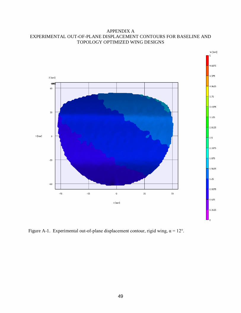
APPENDIX A EXPERIMENTAL OUT-OF-PLANE DISPLACEMENT CONTOURS FOR BASELINE AND
TOPOLOGY OPTIMIZED WING DESIGNS
Figure A-1. Experimental out-of-plane displacement contour, rigid wing, α = 12°.
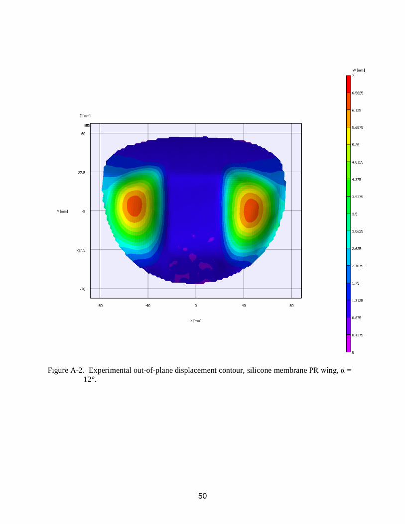
50
Figure A-2. Experimental out-of-plane displacement contour, silicone membrane PR wing, α = 12°.
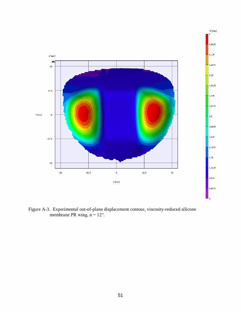
51
Figure A-3. Experimental out-of-plane displacement contour, viscosity-reduced silicone membrane PR wing, α = 12°.
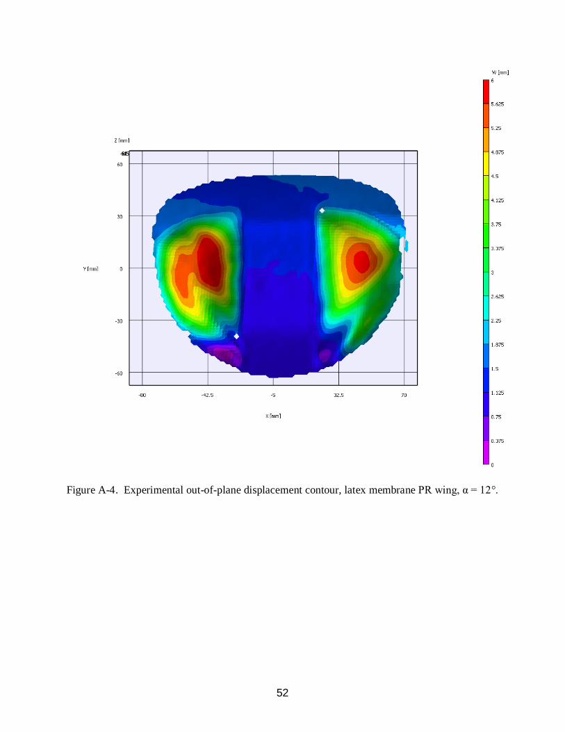
52
Figure A-4. Experimental out-of-plane displacement contour, latex membrane PR wing, α = 12°.
53
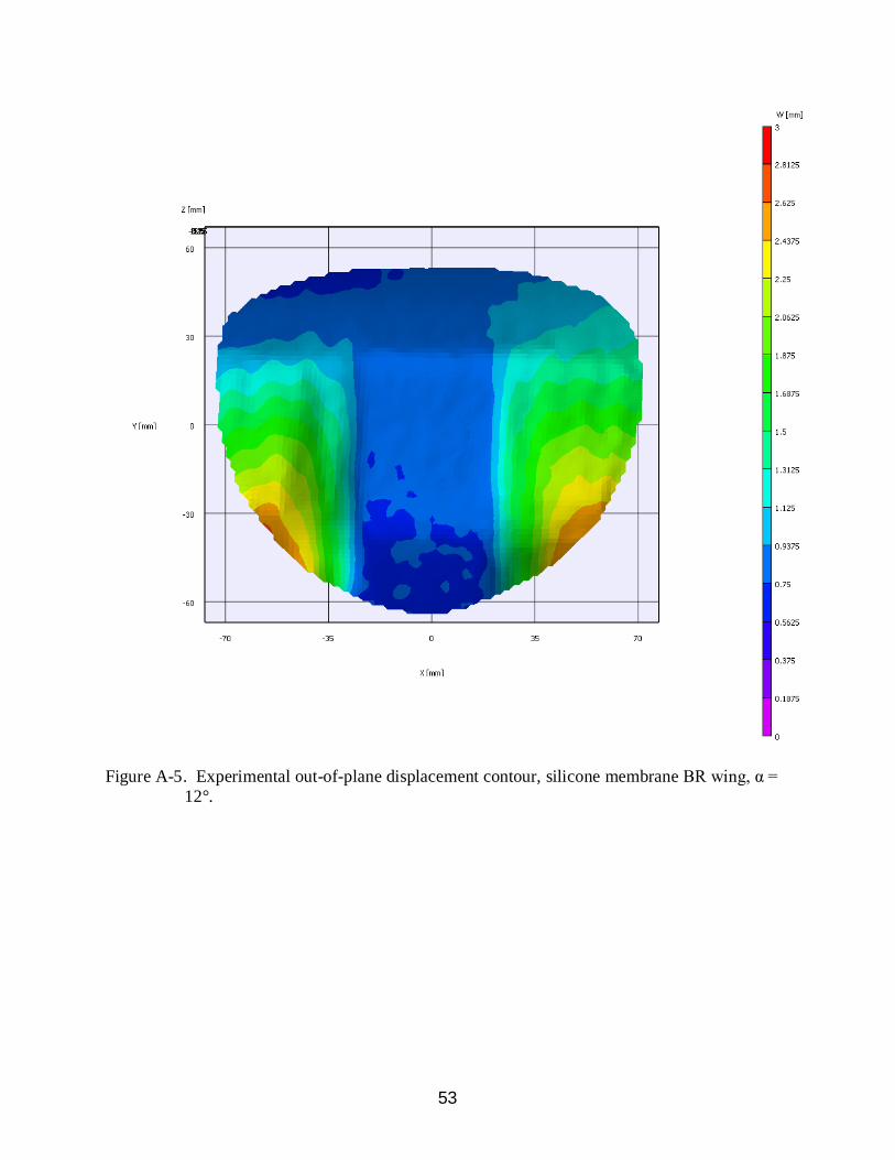
Figure A-5. Experimental out-of-plane displacement contour, silicone membrane BR wing, α = 12°.
54
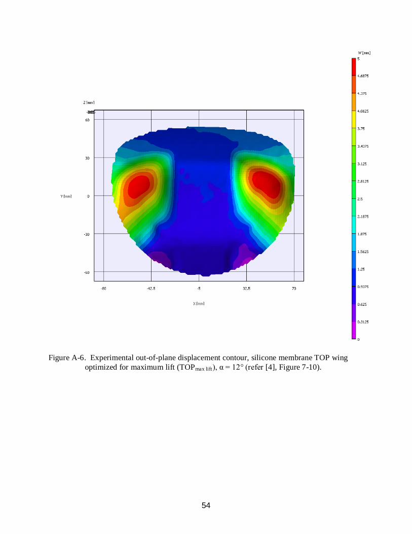
Figure A-6. Experimental out-of-plane displacement contour, silicone membrane TOP wing optimized for maximum lift (TOPmax lift), α = 12° (refer [4], Figure 7-10).

55
Figure A-7. Experimental out-of-plane displacement contour, silicone membrane TOP wing
optimized for minimum lift slope (TOPmin lift slope), α = 12° (refer [4], Figure 7-10).
56
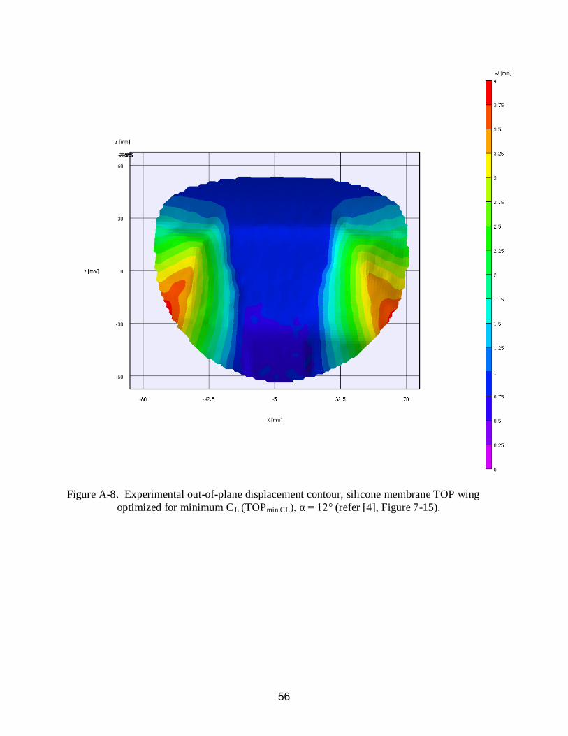
Figure A-8. Experimental out-of-plane displacement contour, silicone membrane TOP wing optimized for minimum CL (TOPmin CL), α = 12° (refer [4], Figure 7-15).
57
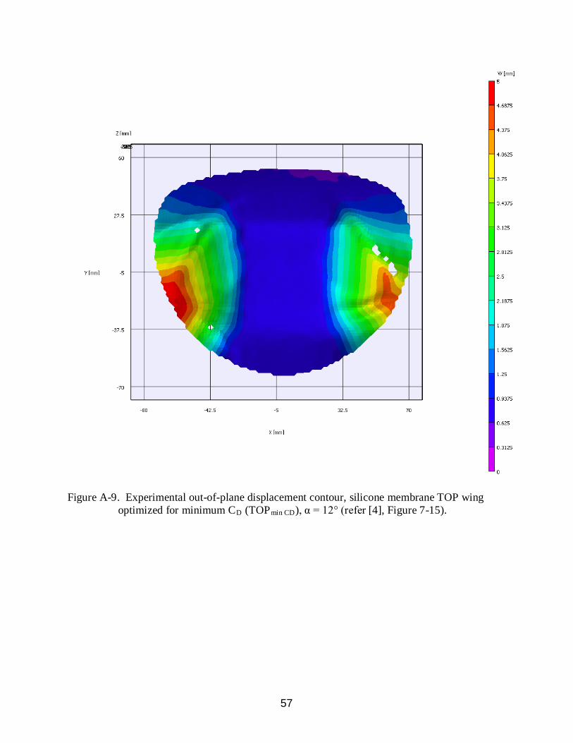
Figure A-9. Experimental out-of-plane displacement contour, silicone membrane TOP wing optimized for minimum CD (TOPmin CD), α = 12° (refer [4], Figure 7-15).

58
Figure A-10. Experimental out-of-plane displacement contour, silicone membrane TOP wing optimized for minimum Cm (TOPmin Cm), α = 12° (refer [4], Figure 7-15).
59
Figure A-11. Experimental out-of-plane displacement contour, silicone membrane TOP wing, single-objective (δ = 1.0) optimized for minimum lift slope (TOPδ = 1), α = 12° (refer [4], Figure 7-18).
60
APPENDIX B NUMERICAL OUT-OF-PLANE DISPLACEMENT MODELS FOR BASELINE AND
TOPOLOGY OPTIMIZED WING DESIGNS, COURTESY OF STANFORD [4]
Figure B-1. Numerical out-of-plane displacement model, rigid wing, α = 12°.
61
Figure B-2. Numerical out-of-plane displacement model, PR wing, α = 12°.

62
Figure B-3. Numerical out-of-plane displacement model, silicone membrane TOP wing optimized for maximum lift (TOPmax lift), α = 12° (refer [4], Figure 7-10).
63
Figure B-4. Numerical out-of-plane displacement model, BR wing, α = 12°.

64
Figure B-5. Numerical out-of-plane displacement model, silicone membrane TOP wing optimized for minimum lift slope (TOPmin lift slope), α = 12° (refer [4], Figure 7-10).

65
Figure B-6. Numerical out-of-plane displacement model, silicone membrane TOP wing, single-objective (δ = 1.0) optimized for minimum lift slope (TOPδ = 1), α = 12° (refer [4], Figure 7-18).
66
LIST OF REFERENCES
[1] Stanford, B., Ifju, P., Albertani, R., Shyy, W., “Fixed Membrane Wings for Micro Air Vehicles: Experimental Characterization, Numerical Modeling, and Tailoring,” Progress in Aerospace Sciences, Vol.44, No. 4, 2008, pp. 258-294.
[2] Ifju, P., Jenkins, D., Ettinger, S., Lian, Y., Shyy, W., Waszak, M., “Flexible-Wing-Based
Micro Air Vehicles,” 40th
AIAA Aerospace Sciences Meeting & Exhibit, Reno, NV, AIAA Paper 2002-0705, 2002.
[3] Stanford, B., Ifju, P., “Membrane Micro Air Vehicles with Adaptive Aerodynamic Twist: Numerical Modeling,” Journal of Aerospace Engineering, Vol. 22, No. 2, 2009, pp. 173-184.
[4] Stanford, B., “Aeroelastic Analysis and Optimization of Membrane Micro Air Vehicle
Wings,” Ph.D. Dissertation, Department of Mechanical and Aerospace Engineering, University of Florida, Gainesville, FL, 2008.
[5] Pornsin-sirirak, T., Tai, Y., Nassef, H., Ho, C., “Titanium-alloy MEMS Wing
Technology for a Micro Aerial Vehicle Application,” Sensors and Actuators A: Physical, Vol. 89, No. 1-2, 2000, pp. 95-103.
[6] Song, A., Tian, X., Israeli, E., Galvao, R., Bishop, K., Swartz, S., Breuer, K., “The Aero-
Mechanics of Low Aspect Ratio Compliant Membrane Wings, with Applications to Animal Flight,” 46th
AIAA Aerospace Sciences Meeting and Exhibit, Reno, NV, AIAA Paper 2008-517, 2008.
[7] Leylek, E., Manzo, J., Garcia, E., “A Bat-wing Aircraft Using the Smart Joint Mechanism,” 3rd
International Conference on Smart Materials, Structures, and Systems, Acireale, Sicily, 2008.
[8] Manzo, J., Leylek, E., Garcia, E., “Drawing Insight from Nature: A Bat Wing for Morphing Aircraft,” ASME Conference on Smart Materials, Adaptive Structures, and Intelligent Systems, Ellicott City, MD, 2008.
[9] Abdulrahim, M., Garcia, H., Lind, R., “Flight Characteristics of Shaping the Membrane
Wing of a Micro Air Vehicle,” Journal of Aircraft, Vol. 42, No.1, 2005, pp. 131-137. [10] Waldman, R., Song, A., Riskin, D., Swartz, S., Breuer, K., “Aerodynamic Behavior of
Compliant Membranes as Related to Bat Flight,” 38th
Fluid Dynamics Conference and Exhibit, Seattle, WA, 2008.
[11] Callahan, R., Garcia, E., “Bio-Inspired Bat Wing Design and Fabrication,” AIAA Region I-NE Student Conference, Worcester, MA, 2009.
[12] Fink, J., Reactive Polymers Fundamentals and Applications: A Concise Guide to
Industrial Polymers, William Andrew Publishing, Norwich, NY, 2005.
67
[13] Keller, M., White, S., Sottos, N., “A Self-Healing Poly (Dimethyl Siloxane) Elastomer,”
Advanced Functional Materials, Vol. 17, No. 14, 2007, pp. 2399-2404. [14] Boria, F., “Optimization of a Morphing Wing Geometry Using a Genetic Algorithm with
Wind Tunnel Hardware-in-the-Loop,” M.S. Thesis, Department of Mechanical and Aerospace Engineering, University of Florida, Gainesville, FL, 2007.
[15] Dally, J., Riley, W., Experimental Stress Analysis, College House Enterprises, Knoxville,
TN, 2005. [16] Lee, K., “Development of Unmanned Aerial Vehicle (UAV) for Wildlife Surveillance,”
M.S. Thesis, Department of Mechanical and Aerospace Engineering, University of Florida, Gainesville, FL, 2004.
68
BIOGRAPHICAL SKETCH
Albert Y. Lin was born in Taipei, Taiwan in 1980. His family moved to the United States
in 1983, where his father attended graduate school at Auburn University. He later grew up in
Tallahassee, Florida and graduated from Lincoln High School in 1999. Lin enrolled at the
University of Florida later that year and received a Bachelor of Science in Aerospace
Engineering in 2004. After graduating, he worked as an airborne LiDAR operator/analyst at the
National Center for Airborne Laser Mapping (NCALM), conducting over 250 flight hours of
aerial mapping across the United States in a Cessna 337 Skymaster. Lin joined the Micro Air
Vehicle (MAV) Laboratory in 2007 with hopes of pursuing a graduate degree under the
advisement of Dr. Peter Ifju. During this time, he was a member of a talented team of MAV
researchers who designed a number of state-of-the-art aircraft. Lin received a Master of Science
in Aerospace Engineering from the University of Florida in December 2009.