universal version installation and programming … - installation and programming instructions 3 1....
TRANSCRIPT
Universal Version Installation and Programming Instructions

2 AGM - Installation and Programming Instructions
Table of Contents
1. Introduction ................................................................................................31.1 Main Features ......................................................................................3
2. AGM Components......................................................................................43. Installation ..................................................................................................5
3.1 Preliminary Considerations ..................................................................53.2 Installing the AGM................................................................................5
3.2.1. SIM Card Installation ..................................................................53.2.2. Wall Mounting (Metal Box Installation) .......................................6
4. Wiring the AGM..........................................................................................74.1 LED Indications....................................................................................74.2 Automatic GSM Signal Level Measurement ........................................8
5. AGM Operation Mode ................................................................................96. Monitoring Station Reporting......................................................................97. Inputs .......................................................................................................108. Outputs.....................................................................................................10
8.1 Output Events ....................................................................................108.2 CLIP Control ......................................................................................11
9. Follow Me Report .....................................................................................119.1 Follow Me Events...............................................................................11
10. SMS User Remote Control Functions ......................................................1211. AGM Programming ..................................................................................13
11.1 Installer SMS Programming.............................................................1311.2 SMS Programming Commands .......................................................15
12. Technical Specifications...........................................................................2013. Appendix: Telephone Number Conversion in Line Simulation Mode.......21
AGM - Installation and Programming Instructions 3
1. Introduction
RISCO Group’s AGM, Universal Advanced GSM/GPRS Stand alone Module, is a cellular communication module enabling any existing security panel to communicate through the GSM cellular network.
The AGM can be used as the main communication line or as a backup to PSTN line using telephone line simulation.
1.1 Main Features
Full PSTN line simulation
Primary or backup GSM/GPRS operation modes
4 alarm inputs
4 outputs that can be activated by system events, SMS or CLIP control
Report to two Monitoring Stations by SMS, GPRS or voice (using line simulation)
Selective event reporting to 8 Follow Me destinations using SMS, E-mail or voice messages (using the Plug On voice module)
3 LED Status indication
Advanced remote SMS system control
Local / Remote configuration using the AGM Configuration Software through the GSM data channel (9600 bps) or by SMS commands
GSM signal supervision and level measurement
Wall and cover tamper protection
Prepaid SIM card support
Backup battery charger and battery protection feature
Quad Band GSM 850/900/1800/1900MHz
Output and Input status verification by SMS commands
4 AGM - Installation and Programming Instructions
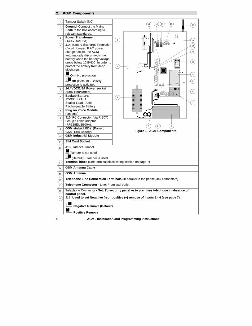
2. AGM Components
1 Tamper Switch (NC)
2 Ground: Connect the Mains Earth to the bolt according to relevant standards.
3 Power Transformer:(14.4VDC/1.5A)J14: Battery discharge Protection Circuit Jumper. If AC power outage occurs, the AGM automatically disconnects the battery when the battery voltage drops below 10.5VDC, in order to protect the battery from deep discharge.
On - No protection
4
Off (Default) - Battery protection is activated
5 14.4VDC/1.5A Power socket(from Transformer)
6 Backup Battery:12VDC/1.2A/HSealed Lead - Acid Rechargeable Battery
7 Plug on Voice Module(optional)
8 J10: PC Connector (via RISCO Group's cable adaptor (RP128EUSB00A).
9 GSM status LEDs: (Power, GSM, Low Battery)
10 GSM Industrial Module
11 SIM Card Socket
BUS
CO
MTM
P
J13
+12
V
GN
D
LOC
K
OP
EN
RED BLK YELGRN
2
LD1 LD3 LD2
1
L.BA
T
GS
M
PO
WE
R
J14
INP
UT
12
34
N.C
CN
.OU
o2
Uo
3Uo
4A
UX
PL
AY
RE
C
3
654
7
J158
9
10
11
12
13
14
1516171819
Figure 1. AGM Components
12 J13: Tamper Jumper
Tamper is not used
(Default) - Tamper is used 13 Terminal block (See terminal block wiring section on page 7)
14 GSM Antenna Cable
15 GSM Antenna
16 Telephone Line Connection Terminals (in parallel to the phone jack connectors)
17 Telephone Connector - Line: From wall outlet
18 Telephone Connector - Set: To security panel or to premises telephone in absence of control panel.
19 J15: Used to set Negative (-) or positive (+) remove of inputs 1 - 4 (see page 7).
Negative Remove (Default)
Positive Remove
AGM - Installation and Programming Instructions 5
3. Installation
3.1 Preliminary Considerations
� The AGM Module should be located in a safe and dry place, away from radio and electromagnetic transmitting devices.
� Select a mounting location near a 110/220VAC electrical power supply.
3.2 Installing the AGM
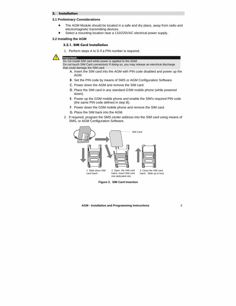
3.2.1. SIM Card Installation
1. Perform steps A to D if a PIN number is required:
Important:Do not install SIM card while power is applied to the AGM.Do not touch SIM Card connectors! If doing so, you may release an electrical discharge that could damage the SIM card.
A. Insert the SIM card into the AGM with PIN code disabled and power up the AGM.
B. Set the PIN code by means of SMS or AGM Configuration Software.
C. Power down the AGM and remove the SIM card.
D. Place the SIM card in any standard GSM mobile phone (while powered down).
E. Power up the GSM mobile phone and enable the SIM's required PIN code (the same PIN code defined in step B).
F. Power down the GSM mobile phone and remove the SIM card.
G. Place the SIM back into the AGM.
2. If required, program the SMS center address into the SIM card using means of SMS, or AGM Configuration Software.
LO
CK
OP
EN
LO
CK
OP
EN
LO
CK
OP
EN
SIM Card
1. Slide down SIMcard hatch .
2. Open the SIM cardhatch. Insert SIM cardinto dedicated slot.
3. Close the SIM cardhatch . Slide up to lock.
Figure 2. SIM Card Insertion

6 AGM - Installation and Programming Instructions
3.2.2. Wall Mounting (Metal Box Installation)
4
2
1Front Cover
Front CoverPivots
3 5
7
1
MountingScrews
MountingScrews
Front Cover Securing Screws
MountingHoles
MountingHoles
6
Metal Casing
8
Cable Passage
Figure 3. AGM– Installation
1. Remove the two screws securing the AGM front cover (2, Figure 3).
2. Tilt and rotate the front cover downwards until it locks vertically to the casing (alternately lift up to remove the cover).
3. Use the metal casing as a template for marking the installation holes (mark through the mounting holes, see 5 and 7, Figure 3).
4. Drill the four installation holes in the wall and insert anchors (if necessary).
5. Insert external cables (GND, power, and phone lines) through the cable passage (6, Figure 3).
6. Align the AGM with the mounting holes and fasten it firmly to the wall with all four supplied screws (1, Figure 3).
7. Attach the AGM antenna.
8. Connect the AGM backup battery cables to the backup battery.
9. Connect the AGM Module to mains.
10. Install the front cover in its place (in a reverse sequence of the removal (see Figure 3).
AGM - Installation and Programming Instructions 7
4. Wiring the AGM
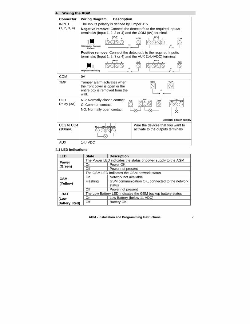
Connector Wiring Diagram Description INPUT(1, 2, 3, 4)
The Inputs polarity is defined by jumper J15. Negative remove: Connect the detector/s to the required Input/s terminal/s (Input 1, 2, 3 or 4) and the COM (0V) terminal.
NR (Negative Remove) (Default)
1 2 3 4INPUT
COM
NO
1 2 3 4 COM
NC
INPUT
Positive remove: Connect the detector/s to the required Input/s terminal/s (Input 1, 2, 3 or 4) and the AUX (14.4VDC) terminal.
PR (Positive Remove)
1 2 3 4INPUT
AUX
NO
1 2 3 4INPUT
AUX
NC
COM 0V
TMP Tamper alarm activates when the front cover is open or the entire box is removed from the wall.
COM TMP
NC
UO1Relay (3A)
NC: Normally closed contact C: Common contactNO: Normally open contact
COMAUX N.C C N.OUO1
N.C C N.OUO1
External power supply
UO2 to UO4 (100mA)
UO2 UO3 UO4 AUX Wire the devices that you want to activate to the outputs terminals
AUX 14.4VDC
4.1 LED Indications
LED State DescriptionThe Power LED indicates the status of power supply to the AGMOn Power OK
Power(Green)
Off Power not present The GSM LED Indicates the GSM network status On Network not available Flashing GSM communication OK, connected to the network
status
GSM(Yellow)
Off Power not present The Low Battery LED Indicates the GSM backup battery status On Low Battery (below 11 VDC)
L.BAT (LowBattery, Red) Off Battery OK
8 AGM - Installation and Programming Instructions
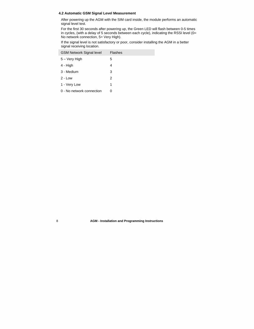
4.2 Automatic GSM Signal Level Measurement
After powering up the AGM with the SIM card inside, the module performs an automatic signal level test.
For the first 30 seconds after powering up, the Green LED will flash between 0-5 times in cycles, (with a delay of 5 seconds between each cycle), indicating the RSSI level (0= No network connection, 5= Very High).
If the signal level is not satisfactory or poor, consider installing the AGM in a better signal receiving location.
GSM Network Signal level Flashes
5 – Very High 5
4 - High 4
3 - Medium 3
2 - Low 2
1 - Very Low 1
0 - No network connection 0
AGM - Installation and Programming Instructions 9
5. AGM Modes of Operation
The AGM is connected serially between the telephone line (if available) and additional devices using the same telephone line service.
Based on the AGM line simulation capability, the module constantly checks the availability of both the PSTN and the GSM lines.
During regular operation mode, all calls and data transmission are carried out using the primary line (PSTN-default or GSM). In the case of trouble with the main line, the line is routed to the backup.
At the end of a call, the availability of the main line is rechecked.
If the line is not restored, the system stays on the back up line until the restoration of the main line.
The AGM has three operation modes:
GSM Back Up - The outgoing calls are performed through the PSTN line. When the PSTN line is not available for the time defined in PSTN Lost Delay parameter, the outgoing calls will be directed through the GSM network.
GSM Only - The outgoing calls are performed through the GSM voice channel only. Use this option when no PSTN line is available.
GSM Main - The outgoing calls are performed through the GSM voice channel. When the GSM network is not available for the time defined in GSM Loss Delay parameter, the outgoing calls will be directed through the PSTN line.
6. Monitoring Station Reporting
The AGM enables to report events to two different Monitoring Stations, using Contact ID or SIA formats via three different channels: Voice, SMS, or GPRS.
The security level achieved varies from one technology to another, as described below.
� Voice channel Full event report using PSTN simulation operation mode when connected to a security panel.
� SMS Channel AGM input events and internal AGM events can be sent to the Monitoring Station using encrypted SMS messages (128 BIT AES encryption).The event messages are received by RISCO Group's IP/GSM Receiver Software located in the MS site. The IP/GSM Receiver translates the SMS messages to standard protocols used by the Monitoring Station applications (For example; Contact ID, SIA etc).
� GPRS Channel AGM input events and internal AGM events can be sent over the GPRS network using TCP/IP protocol to RISCO Group's IP/GSM Receiver software located at the MS site. All messages are encrypted (128 BIT AES encryption is used).
Note:For GPRS communication, the GPRS channel in the SIM card has to be enabled.
10 AGM - Installation and Programming Instructions
7. Inputs
The AGM has four inputs, which NC and NO devices can be connected to.
Inputs can be activated by negative or positive remove according to the J15 Jumper position.
Each input event and its restore can be reported to the Monitoring Station (by SMS or GPRS) or to any of the 8 Follow Me destinations ( by SMS, Voice message or Email)
Triggering of input event can be defined to be immediate or after a delay.
Each input can be defined as a 24-hour type (constantly activated) or as an Arm/Disarm type (activated or deactivated by a remote SMS user command).
Input 3 can also be defined as type “Switch from PSTN to GSM”. When a phone line is connected to the AGM, the user has the ability to manually switch the outgoing line from PSTN to GSM (Latch operation).
Input 4 can also be defined as type “Stop Follow Me”. When triggered it will stop all Follow Me calls following the current event.
8. Outputs
The AGM has four outputs (one 3A relay output and three-100mA Open Collector outputs) that can be activated automatically according to various events, or manually by SMS commands from pre defined Follow Me telephone numbers. Each output can be defined to be pulsed or latched.
8.1 Output Events
Output defined as “Follow Event” can automatically be activated by the following events: � Input 1 - 4 event: Activates following triggering / restore of an input. � Tamper: Activates following AGM tamper alarm. � PSTN Lost: Activates following a loss of PSTN line (connected to the GSM).
The output will be activated after the defined PSTN Loss Delay time. � GSM Trouble: Activates in the following cases:
• There is no SIM card in the AGM or SIM is faulty • GSM RSSI signal level is low • GSM network trouble
� Mains power Loss: Activates when the source of the main AC power is interrupted. The output will be activated after the predefined AC Loss Delay time.
� Low Battery: Activates when the AGM battery has insufficient reserve capacity and the voltage is lower than 11V.
� SIM Card Expire: Activates 30 days before the time defined in the SIM Expire timer.
� Periodic Test: Activates following the time defined in the Periodic Test timer. � GSM+PSTN Loss: Activates following loss of PSTN and GSM network.

AGM - Installation and Programming Instructions 11
8.2 CLIP Control
Output 1 can be defined as CLIP control type. The CLIP (Calling Line Identity Presentation) feature enables the user to activate output 1 from Follow Me numbers authorized with this function, without being charged for a call from this phone to the AGM.To be able to perform this operation, the user has to initiate a call to the AGM and hang up after the second ring. While waiting, the AGM recognizes the telephone number (using the caller ID feature of the GSM network) that the call is initiated from, and activates output 1.
9. Follow Me Report
The AGM allows reporting events to eight Follow Me destinations using one of the following three reporting types:
� Voice messaging: Using the optional Plug on voice module (RP200GSV00A) the AGM enables to assign events with short audible messages. Up to four pre-recorded messages can be recorded (10 second message each).
� SMS: Predefined SMS event messages can be sent to a Follow Me number.
Note:SMS input event messages can be manually defined according to the installation type.
� E-mail: The AGM can E-mail event messages to predefined E-mail addresses using GPRS. In order to do so, GPRS channel must be activated on the SIM and the GPRS parameters should be defined (see page 18).
9.1 Follow Me Events
Event Event description SMS Default Message
Input 1-4 event Report to Follow Me will be established when an input is triggered
I1:"Intruder alarm" I2: "Panic alarm" I3: "Fire alarm" I4: "Emergency
alarm"Input 1-4 restore Report to Follow Me will be established when an input is
restored to normal condition I1:"Intruder restore" I2: "Panic restore" I3: "Fire restore" I4: "Emergency res."
Tamper Report to Follow Me will be established following a tamper alarm
"GSM box tamper"
Tamper restore Report to Follow Me will be established following to the restore of tamper alarm
"GSM box tamper OK
No PSTN Report to Follow Me will be established following loss of PSTN line (connected to the GSM). If PSTN Loss Delay time period is defined, the message will be sent after the delay time
"Phone Line Fail"
PSTN Restore Report to Follow Me will be established following to the restore of PSTN line (connected to the GSM) to normal condition
"Phone Line OK"
GSM Restored Report to Follow Me will be established following to the restore of the GSM line to normal condition. The AGM can establish a connection using the GSM network.
"GSM line OK"
12 AGM - Installation and Programming Instructions
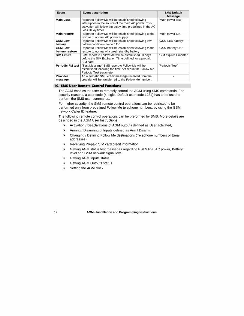
Event Event description SMS Default Message
Main Loss Report to Follow Me will be established following interruption in the source of the main AC power. This activation will follow the delay time predefined in the AC Loss Delay timer
"Main power loss"
Main restore Report to Follow Me will be established following to the restore of normal AC power supply
"Main power OK"
GSM Low battery
Report to Follow Me will be established following low battery condition (below 11V)
"GSM Low battery"
GSM Low battery restore
Report to Follow Me will be established following to the restore to normal of a weak standby battery
"GSM battery OK"
SIM Expire SMS report to Follow Me will be established 30 days before the SIM Expiration Time defined for a prepaid SIM card.
"SIM expire: 1 month"
Periodic FM test "Test Message" SMS report to Follow Me will be established following the time defined in the Follow Me Periodic Test parameter
"Periodic Test"
Providermessage
An automatic SMS credit message received from the provider will be transferred to the Follow Me number.
-
10. SMS User Remote Control Functions
The AGM enables the user to remotely control the AGM using SMS commands. For security reasons, a user code (4 digits. Default user code 1234) has to be used to perform the SMS user commands.
For higher security, the SMS remote control operations can be restricted to be performed only from predefined Follow Me telephone numbers, by using the GSM network Caller ID feature.
The following remote control operations can be preformed by SMS. More details are described in the AGM User Instructions.
Activation / Deactivations of AGM outputs defined as User activated,
Arming / Disarming of Inputs defined as Arm / Disarm
Changing / Defining Follow Me destinations (Telephone numbers or Email addresses)
Receiving Prepaid SIM card credit information
Getting AGM status test messages regarding PSTN line, AC power, Battery level and GSM network signal level
Getting AGM Inputs status
Getting AGM Outputs status
Setting the AGM clock
AGM - Installation and Programming Instructions 13
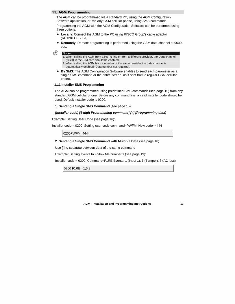
11. AGM Programming
The AGM can be programmed via a standard PC, using the AGM ConfigurationSoftware application, or, via any GSM cellular phone, using SMS commands.
Programming the AGM with the AGM Configuration Software can be performed using three options:
� Locally: Connect the AGM to the PC using RISCO Group's cable adaptor (RP128EUSB00A).
� Remotely: Remote programming is performed using the GSM data channel at 9600 bps.
Notes:1. When calling the AGM from a PSTN line or from a different provider, the Data channel
(CSO) in the SIM card should be enabled.2. When calling the AGM from a number of the same provider the data channel is
automatically enabled (Data number not required).
� By SMS: The AGM Configuration Software enables to send each parameter as a single SMS command or the entire screen, as if sent from a regular GSM cellular phone.
11.1 Installer SMS Programming
The AGM can be programmed using predefined SMS commands (see page 15) from any standard GSM cellular phone. Before any command line, a valid installer code should be used. Default installer code is 0200.
1. Sending a Single SMS Command (see page 15)
[Installer code] [4-digit Programming command] [=] [Programming data]
Example: Setting User Code (see page 16):
Installer code = 0200; Setting user code command=PWFM; New code=4444
0200PWFM=4444
2. Sending a Single SMS Command with Multiple Data (see page 18)
Use [,] to separate between data of the same command
Example: Setting events to Follow Me number 1 (see page 19):
Installer code = 0200; Command=F1RE Events: 1 (Input 1), 5 (Tamper), 8 (AC loss)
0200 F1RE =1,5,8
14 AGM - Installation and Programming Instructions
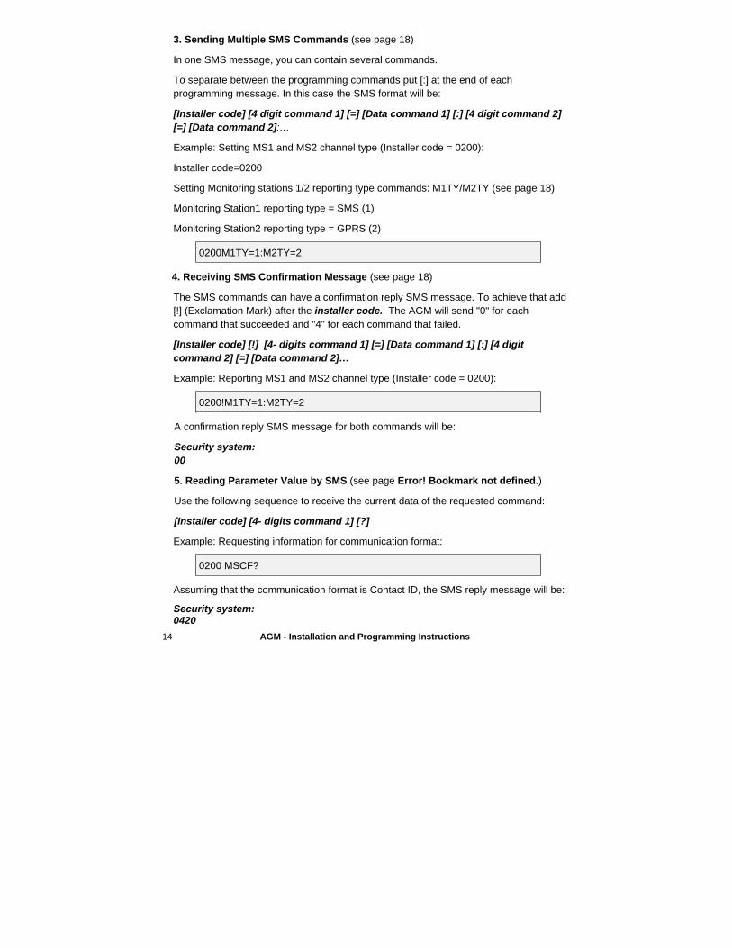
3. Sending Multiple SMS Commands (see page 18)
In one SMS message, you can contain several commands.
To separate between the programming commands put [:] at the end of each programming message. In this case the SMS format will be:
[Installer code] [4 digit command 1] [=] [Data command 1] [:] [4 digit command 2] [=] [Data command 2]:…
Example: Setting MS1 and MS2 channel type (Installer code = 0200):
Installer code=0200
Setting Monitoring stations 1/2 reporting type commands: M1TY/M2TY (see page 18)
Monitoring Station1 reporting type = SMS (1)
Monitoring Station2 reporting type = GPRS (2)
0200M1TY=1:M2TY=2
4. Receiving SMS Confirmation Message (see page 18)
The SMS commands can have a confirmation reply SMS message. To achieve that add [!] (Exclamation Mark) after the installer code. The AGM will send "0" for each command that succeeded and "4" for each command that failed.
[Installer code] [!] [4- digits command 1] [=] [Data command 1] [:] [4 digit command 2] [=] [Data command 2]…
Example: Reporting MS1 and MS2 channel type (Installer code = 0200):
0200!M1TY=1:M2TY=2
A confirmation reply SMS message for both commands will be:
Security system: 00
5. Reading Parameter Value by SMS (see page Error! Bookmark not defined.)
Use the following sequence to receive the current data of the requested command:
[Installer code] [4- digits command 1] [?]
Example: Requesting information for communication format:
0200 MSCF?
Assuming that the communication format is Contact ID, the SMS reply message will be:
Security system: 0420
AGM - Installation and Programming Instructions 15
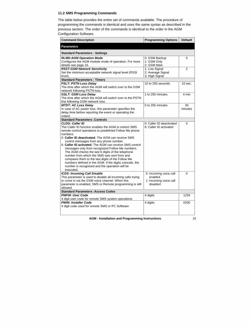
11.2 SMS Programming Commands
The table below provides the entire set of commands available. The procedure of programming the commands is identical and uses the same syntax as described in the previous section. The order of the commands is identical to the order in the AGM Configuration Software.
Command Description Programming Options Default
Parameters
Standard Parameters : Settings
RLMD:AGM Operation Mode Configures the AGM module mode of operation. For more details see page 16.
0: GSM Backup 1: GSM Only 2: GSM Main
0
RSST:GSM Network Sensitivity Set the minimum acceptable network signal level (RSSI level).
1: Low Signal 2: Average Signal3: High Signal
2
Standard Parameters : Timers PSLT: PSTN Loss Delay The time after which the AGM will switch over to the GSM network following PSTN loss.
10 to 255 seconds 10 sec.
GSLT: GSM Loss Delay The time after which the AGM will switch over to the PSTN line following GSM network loss.
1 to 255 minutes 4 min
MTDT: AC Loss Delay In case of AC power loss, this parameter specifies the delay time before reporting the event or operating the output.
0 to 255 minutes 30 minutes
Standard Parameters :Controls CLDG: Caller IDThe Caller ID function enables the AGM to restrict SMS remote control operations to predefined Follow Me phone numbers.0: Caller ID deactivated. The AGM can receive SMS
control messages from any phone number.6: Caller ID activated. The AGM can receive SMS control
messages only from recognized Follow Me numbers. The AGM checks the last 6 digits of the telephone number from which the SMS was sent from and compares them to the last digits of the Follow Me numbers defined in the AGM. If the digits coincide, the number is recognized and the operation will be executed.
0: Caller ID deactivated 6: Caller ID activated
0
ICDS: Incoming Call Disable This parameter is used to disable all incoming calls trying to come in via the GSM voice channel. When this parameter is enabled, SMS or Remote programming is still allowed.
0: Incoming voice call enabled
1: Incoming voice call disabled
0
Standard Parameters :Access Codes PWFM: User Code 4 digit user code for remote SMS system operations
4 digits 1234
PWIN: Installer Code 4 digit code used for remote SMS or PC Software
4 digits 0200
16 AGM - Installation and Programming Instructions
Command Description Programming Options Default
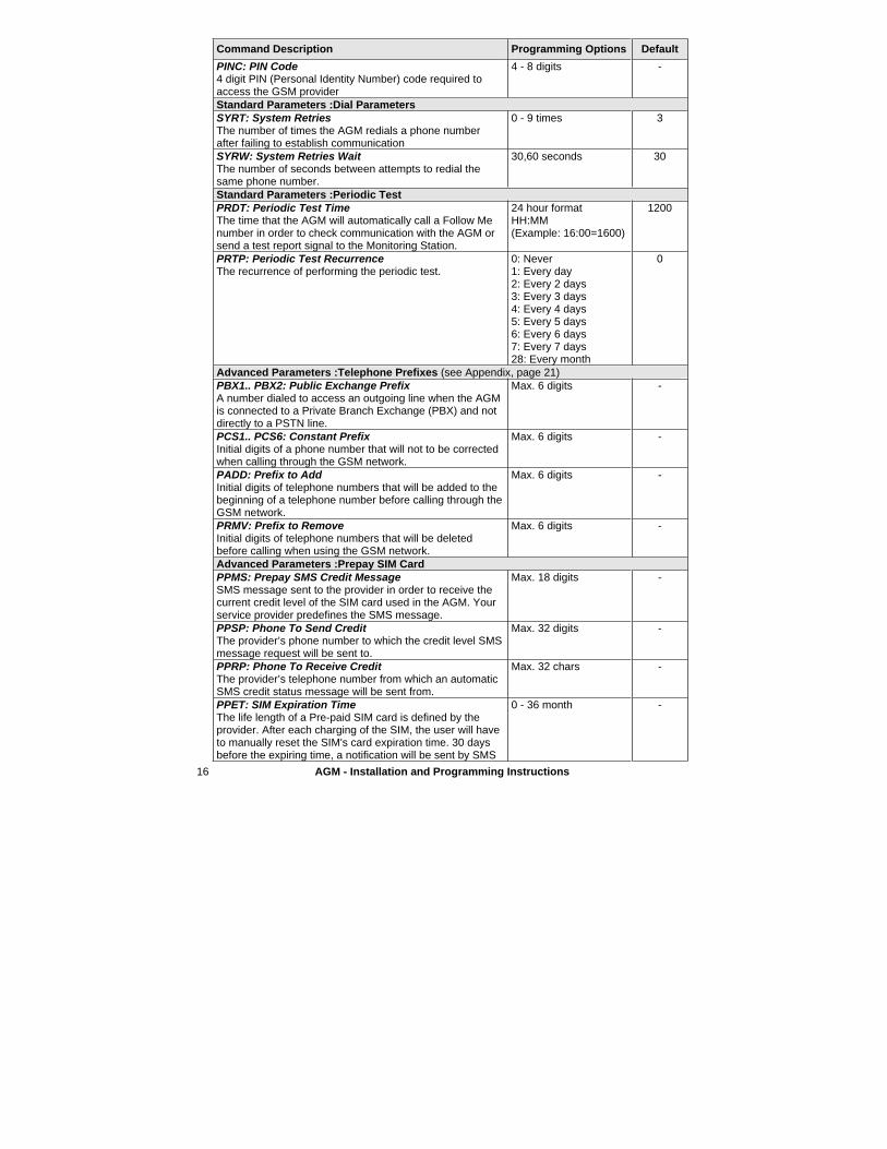
PINC: PIN Code 4 digit PIN (Personal Identity Number) code required to access the GSM provider
4 - 8 digits -
Standard Parameters :Dial Parameters SYRT: System Retries The number of times the AGM redials a phone number after failing to establish communication
0 - 9 times 3
SYRW: System Retries Wait The number of seconds between attempts to redial the same phone number.
30,60 seconds 30
Standard Parameters :Periodic Test PRDT: Periodic Test Time The time that the AGM will automatically call a Follow Me number in order to check communication with the AGM or send a test report signal to the Monitoring Station.
24 hour format HH:MM(Example: 16:00=1600)
1200
PRTP: Periodic Test RecurrenceThe recurrence of performing the periodic test.
0: Never 1: Every day 2: Every 2 days 3: Every 3 days 4: Every 4 days 5: Every 5 days 6: Every 6 days 7: Every 7 days 28: Every month
0
Advanced Parameters :Telephone Prefixes (see Appendix, page 21)PBX1.. PBX2: Public Exchange Prefix A number dialed to access an outgoing line when the AGM is connected to a Private Branch Exchange (PBX) and not directly to a PSTN line.
Max. 6 digits -
PCS1.. PCS6: Constant Prefix Initial digits of a phone number that will not to be corrected when calling through the GSM network.
Max. 6 digits -
PADD: Prefix to Add Initial digits of telephone numbers that will be added to the beginning of a telephone number before calling through the GSM network.
Max. 6 digits -
PRMV: Prefix to Remove Initial digits of telephone numbers that will be deleted before calling when using the GSM network.
Max. 6 digits -
Advanced Parameters :Prepay SIM Card PPMS: Prepay SMS Credit Message SMS message sent to the provider in order to receive the current credit level of the SIM card used in the AGM. Your service provider predefines the SMS message.
Max. 18 digits -
PPSP: Phone To Send Credit The provider’s phone number to which the credit level SMS message request will be sent to.
Max. 32 digits -
PPRP: Phone To Receive Credit The provider’s telephone number from which an automatic SMS credit status message will be sent from.
Max. 32 chars -
PPET: SIM Expiration Time The life length of a Pre-paid SIM card is defined by the provider. After each charging of the SIM, the user will have to manually reset the SIM's card expiration time. 30 days before the expiring time, a notification will be sent by SMS
0 - 36 month -
AGM - Installation and Programming Instructions 17
Command Description Programming Options Default
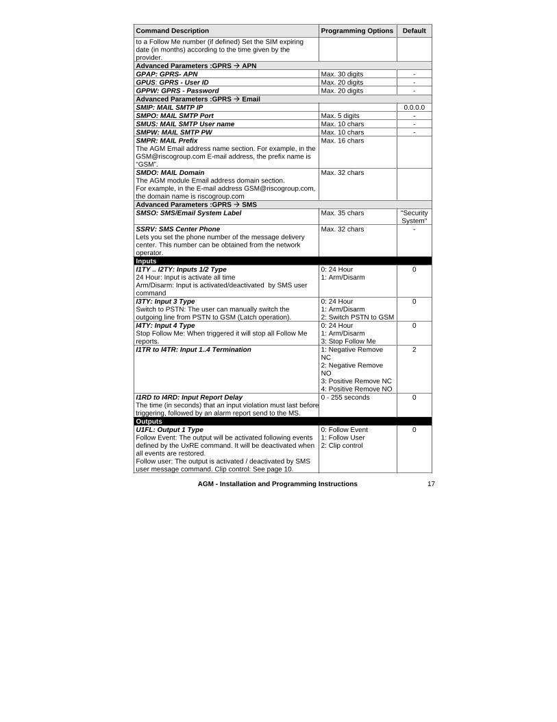
to a Follow Me number (if defined) Set the SIM expiring date (in months) according to the time given by the provider.Advanced Parameters :GPRS � APN GPAP: GPRS- APN Max. 30 digits - GPUS: GPRS - User ID Max. 20 digits - GPPW: GPRS - Password Max. 20 digits - Advanced Parameters :GPRS � Email SMIP: MAIL SMTP IP 0.0.0.0 SMPO: MAIL SMTP Port Max. 5 digits - SMUS: MAIL SMTP User name Max. 10 chars - SMPW: MAIL SMTP PW Max. 10 chars - SMPR: MAIL Prefix The AGM Email address name section. For example, in the [email protected] E-mail address, the prefix name is “GSM”.
Max. 16 chars
SMDO: MAIL Domain The AGM module Email address domain section. For example, in the E-mail address [email protected], the domain name is riscogroup.com
Max. 32 chars
Advanced Parameters :GPRS � SMS SMSO: SMS/Email System Label Max. 35 chars "Security
System"SSRV: SMS Center Phone Lets you set the phone number of the message delivery center. This number can be obtained from the network operator.
Max. 32 chars -
InputsI1TY .. I2TY: Inputs 1/2 Type 24 Hour: Input is activate all time Arm/Disarm: Input is activated/deactivated by SMS user command
0: 24 Hour 1: Arm/Disarm
0
I3TY: Input 3 Type Switch to PSTN: The user can manually switch the outgoing line from PSTN to GSM (Latch operation).
0: 24 Hour 1: Arm/Disarm 2: Switch PSTN to GSM
0
I4TY: Input 4 Type Stop Follow Me: When triggered it will stop all Follow Me reports.
0: 24 Hour 1: Arm/Disarm 3: Stop Follow Me
0
I1TR to I4TR: Input 1..4 Termination 1: Negative Remove NC2: Negative Remove NO3: Positive Remove NC 4: Positive Remove NO
2
I1RD to I4RD: Input Report Delay The time (in seconds) that an input violation must last beforetriggering, followed by an alarm report send to the MS.
0 - 255 seconds 0
Outputs U1FL: Output 1 Type Follow Event: The output will be activated following events defined by the UxRE command. It will be deactivated when all events are restored. Follow user: The output is activated / deactivated by SMS user message command. Clip control: See page 10.
0: Follow Event 1: Follow User 2: Clip control
0

18 AGM - Installation and Programming Instructions
Command Description Programming Options Default
U2FL to U4FL: Output 2 to Output 4 Type 0: Follow Event 1: Follow User
0
U1TY to U4TY: Output Termination 0: Pulse N.C. 1: Pulse N.O. 2: Latch N.C. 3: Latch N.O.
1
U1PR to U1PR: Output Pulse Delay The time in seconds that the output is activated when triggered.
1-255 seconds 5
U1RE to U4RE: Output Report Event For events description, refer to page 10.
1: Input 1 2: Input 2 3: Input 3 4: Input 4 5: Tamper 6: PSTN loss 7: GSM trouble
8: Main power loss9: Low battery 10: SIM card expired 11: Periodic test 12: PSTN+GSM loss
0
Follow Me Parameters F1TY to F8TY: Follow Me Type The format of event reports to the Follow Me. For additional information, refer to page 11.
0: Voice message 1: SMS 2: Email
0
F1TL to F8TL: Follow Me Phone Number Type in the telephone number including dialing prefixes and area code or special letters for Follow Me defined as SMS or Voice. For more details refer to the Appendix, page 21.
Max. 32 digits -
F1ML to F1ML: Follow Me Email Address Max. 31 chars - F1CA to F8CA: Follow Me Clip Control Define which Follow Me phones will be authorized to perform clip control operation to output 1 (when defined)
0: Not authorized1: Clip authorized
0
VORC: Voice Recurrence The number of times a voice message will be played when establishing a call to a Follow Me number.
1 - 9 4
F1RE to F8RE: Follow Me Report EventChoose the events that will be reported to each Follow Me. For more information refer to page 11.
1: Input 1 2: Input 2 3: Input 3 4: Input 4 5: Tamper 6: PSTN loss
7: GSM trouble 8: Main power loss 9: Low battery 10: SIM card expired 11: Periodic test 12: Provider message
F1RS to F1RS: Follow Me Event RestoreChoose which restore events will be reported to each Follow Me number.
1: Input 1 2: Input 2 3: Input 3 4: Input 4
5: Tamper 6: PSTN loss 8: Main power loss 9: Low battery
V1RE to V4RE : Voice Message Assignment to Follow MeChoose which voice message will follow a specific triggering of an event or message
1: Input 1 2: Input 2 3: Input 3 4: Input 4 5: Tamper
6: PSTN loss8: Main power loss 9: Low battery 11: Periodic test
0
Monitoring Station M1TY or M2TY: Monitoring Station Channel report Type The manner of reporting events to the MS. For additional information refer to page 9.
1: SMS 2: GPRS
1
M1AN or M2AN: Monitoring Station Account Number A six digit customer account number assigned by the Monitoring Station.
Max. 6 digits 111111 222222
M1TL or M2TL: Monitoring Station Telephone Number Max. 32 digits -
AGM - Installation and Programming Instructions 19
Command Description Programming Options Default
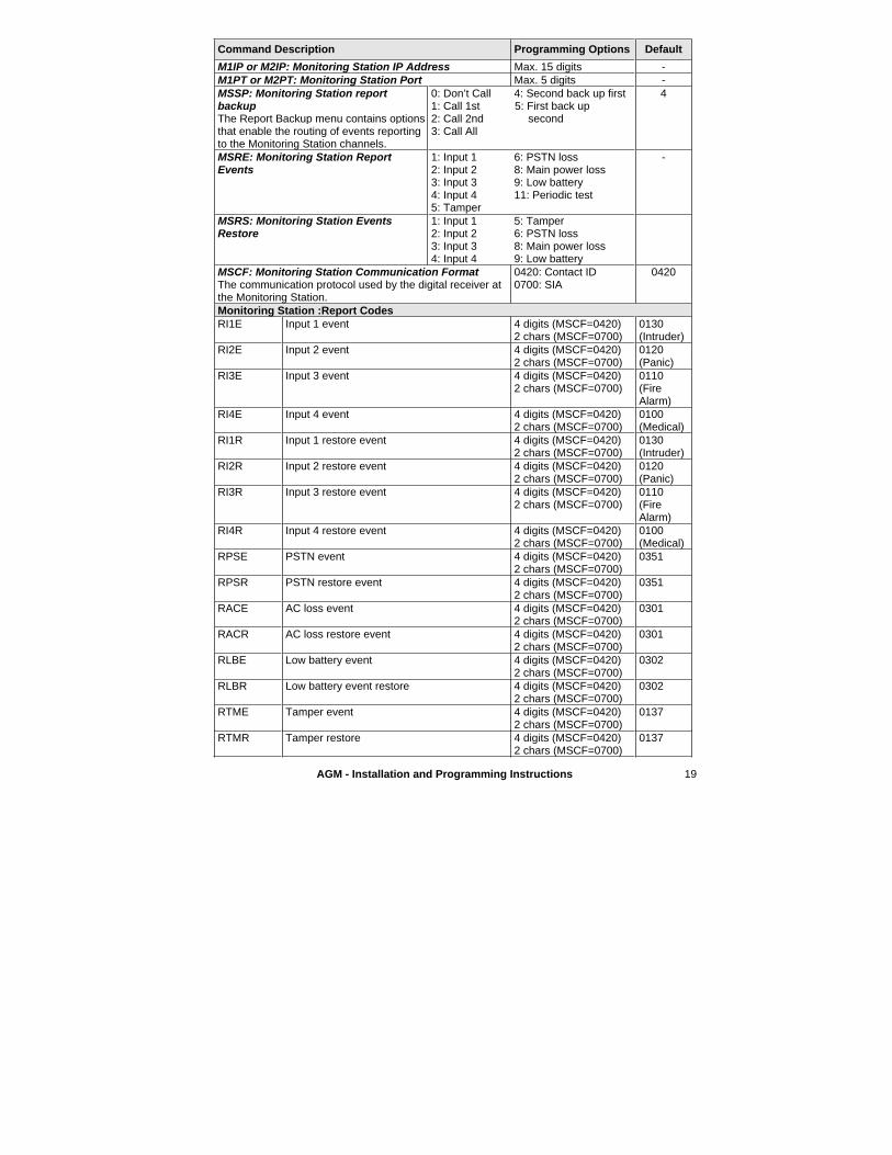
M1IP or M2IP: Monitoring Station IP Address Max. 15 digits - M1PT or M2PT: Monitoring Station Port Max. 5 digits - MSSP: Monitoring Station report backupThe Report Backup menu contains options that enable the routing of events reporting to the Monitoring Station channels.
0: Don’t Call 1: Call 1st 2: Call 2nd3: Call All
4: Second back up first 5: First back up
second
4
MSRE: Monitoring Station Report Events
1: Input 1 2: Input 2 3: Input 3 4: Input 4 5: Tamper
6: PSTN loss 8: Main power loss 9: Low battery 11: Periodic test
-
MSRS: Monitoring Station Events Restore
1: Input 1 2: Input 2 3: Input 3 4: Input 4
5: Tamper 6: PSTN loss 8: Main power loss 9: Low battery
MSCF: Monitoring Station Communication Format The communication protocol used by the digital receiver at the Monitoring Station.
0420: Contact ID 0700: SIA
0420
Monitoring Station :Report Codes RI1E Input 1 event 4 digits (MSCF=0420)
2 chars (MSCF=0700) 0130(Intruder)
RI2E Input 2 event 4 digits (MSCF=0420) 2 chars (MSCF=0700)
0120(Panic)
RI3E Input 3 event 4 digits (MSCF=0420) 2 chars (MSCF=0700)
0110(FireAlarm)
RI4E Input 4 event 4 digits (MSCF=0420) 2 chars (MSCF=0700)
0100(Medical)
RI1R Input 1 restore event 4 digits (MSCF=0420) 2 chars (MSCF=0700)
0130(Intruder)
RI2R Input 2 restore event 4 digits (MSCF=0420) 2 chars (MSCF=0700)
0120(Panic)
RI3R Input 3 restore event 4 digits (MSCF=0420) 2 chars (MSCF=0700)
0110(FireAlarm)
RI4R Input 4 restore event 4 digits (MSCF=0420) 2 chars (MSCF=0700)
0100(Medical)
RPSE PSTN event 4 digits (MSCF=0420) 2 chars (MSCF=0700)
0351
RPSR PSTN restore event 4 digits (MSCF=0420) 2 chars (MSCF=0700)
0351
RACE AC loss event 4 digits (MSCF=0420) 2 chars (MSCF=0700)
0301
RACR AC loss restore event 4 digits (MSCF=0420) 2 chars (MSCF=0700)
0301
RLBE Low battery event 4 digits (MSCF=0420) 2 chars (MSCF=0700)
0302
RLBR Low battery event restore 4 digits (MSCF=0420) 2 chars (MSCF=0700)
0302
RTME Tamper event 4 digits (MSCF=0420) 2 chars (MSCF=0700)
0137
RTMR Tamper restore 4 digits (MSCF=0420) 2 chars (MSCF=0700)
0137
20 AGM - Installation and Programming Instructions
Command Description Programming Options Default
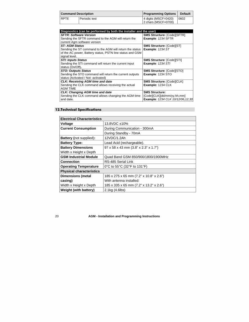
RPTE Periodic test 4 digits (MSCF=0420) 2 chars (MSCF=0700)
0602
Diagnostics (can be performed by both the installer and the user) SFTR: Software VersionSending the SFTR command to the AGM will return the current Agm software version
SMS Structure: [Code][SFTR]Example: 1234 SFTR
ST: AGM Status Sending the ST command to the AGM will return the status of the AC power, Battery status, PSTN line status and GSM signal level.
SMS Structure: [Code][ST]Example: 1234 ST
STI: Inputs Status Sending the STI command will return the current input status (On/Off).
SMS Structure: [Code][STI] Example: 1234 STI
STO: Outputs Status Sending the STO command will return the current outputs status (Activated / Not -activated)
SMS Structure: [Code][STO] Example: 1234 STO
CLK: Receiving AGM time and date Sending the CLK command allows receiving the actual AGM TIME
SMS Structure: [Code][CLK]Example: 1234 CLK
CLK: Changing AGM time and date Sending the CLK command allows changing the AGM time and date.
SMS Structure: [Code][CLK][dd/mm/yy,hh,mm]Example: 1234 CLK 10/12/06,12,30
12.Technical Specifications
Electrical Characteristics Voltage 13.8VDC ±10%
During Communication - 300mA Current Consumption During Standby - 70mA
Battery (not supplied): 12VDC/1.2AhBattery Type: Lead Acid (rechargeable). Battery Dimensions Width x Height x Depth
97 x 58 x 43 mm (3.8” x 2.3” x 1.7”)
GSM Industrial Module Quad Band GSM 850/900/1800/1900MHz Connection RS-485 Serial Link Operating Temperature 0°C to 55°C (32°F to 131°F) Physical characteristicsDimensions (metal casing)Width x Height x Depth
185 x 275 x 65 mm (7.2” x 10.8” x 2.6”) With antenna installed:185 x 335 x 65 mm (7.2” x 13.2” x 2.6”)
Weight (with battery) 2.1kg (4.6lbs)
AGM - Installation and Programming Instructions 21
Appendix: Telephone Number Conversion in Line Simulation Mode
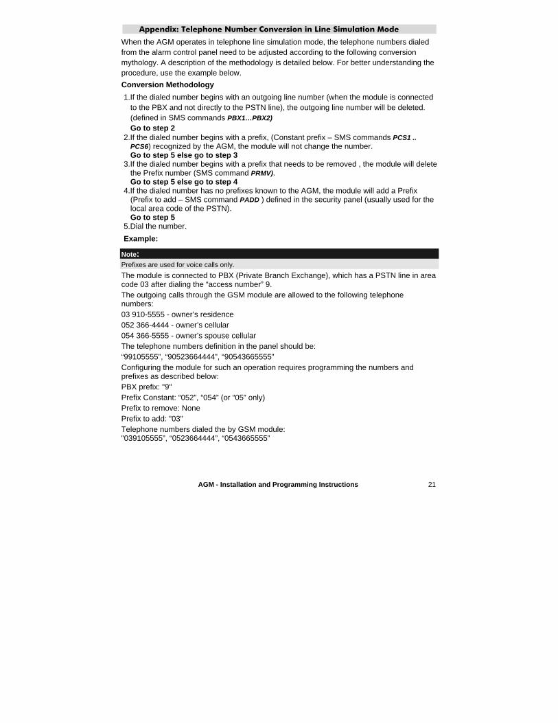
When the AGM operates in telephone line simulation mode, the telephone numbers dialed from the alarm control panel need to be adjusted according to the following conversion mythology. A description of the methodology is detailed below. For better understanding the procedure, use the example below.
Conversion Methodology
1.If the dialed number begins with an outgoing line number (when the module is connected to the PBX and not directly to the PSTN line), the outgoing line number will be deleted. (defined in SMS commands PBX1…PBX2)
Go to step 22.If the dialed number begins with a prefix, (Constant prefix – SMS commands PCS1 ..
PCS6) recognized by the AGM, the module will not change the number. Go to step 5 else go to step 3
3.If the dialed number begins with a prefix that needs to be removed , the module will delete the Prefix number (SMS command PRMV).Go to step 5 else go to step 4
4.If the dialed number has no prefixes known to the AGM, the module will add a Prefix (Prefix to add – SMS command PADD ) defined in the security panel (usually used for the local area code of the PSTN). Go to step 5
5.Dial the number.
Example:
Note:Prefixes are used for voice calls only.
The module is connected to PBX (Private Branch Exchange), which has a PSTN line in area code 03 after dialing the “access number” 9.The outgoing calls through the GSM module are allowed to the following telephone numbers:03 910-5555 - owner’s residence052 366-4444 - owner’s cellular054 366-5555 - owner’s spouse cellularThe telephone numbers definition in the panel should be:“99105555”, “90523664444”, “90543665555” Configuring the module for such an operation requires programming the numbers and prefixes as described below: PBX prefix: "9" Prefix Constant: “052”, “054” (or “05” only) Prefix to remove: None Prefix to add: "03" Telephone numbers dialed the by GSM module: "039105555”, “0523664444”, “0543665555”

22 AGM - Installation and Programming Instructions
AGM - Installation and Programming Instructions 23
RISCO Group Limited Warranty
RISCO Group and its subsidiaries and affiliates ("Seller") warrants its products to be free from defects in materials and workmanship under normal use for 12 months from the date of production. Because Seller does not install or connect the product and because the product may be used in conjunction with products not manufactured by the Seller, Seller cannot guarantee the performance of the security system which uses this product. Seller's obligation and liability under this warranty is expressly limited to repairing and replacing, at Seller's option, within a reasonable time after the date of delivery, any product not meeting the specifications. Seller makes no other warranty, expressed or implied, and makes no warranty of merchantability or of fitness for any particular purpose. In no case shall seller be liable for any consequential or incidental damages for breach of this or any other warranty, expressed or implied, or upon any other basis of liability whatsoever.Seller's obligation under this warranty shall not include any transportation charges or costs of installation or any liability for direct, indirect, or consequential damages or delay. Seller does not represent that its product may not be compromised or circumvented; that the product will prevent any persona; injury or property loss by burglary, robbery, fire or otherwise; or that the product will in all cases provide adequate warning or protection. Buyer understands that a properly installed and maintained alarm may only reduce the risk of burglary, robbery or fire without warning, but is not insurance or a guaranty that such will not occur or that there will be no personal injury or property loss as a result. Consequently seller shall have no liability for any personal injury, property damage or loss based on a claim that the product fails to give warning. However, if seller is held liable, whether directly or indirectly, for any loss or damage arising from under this limited warranty or otherwise, regardless of cause or origin, sellers Maximum liability shall not exceed the purchase price of the product, which shall be complete and exclusive remedy against seller. No employee or representative of Seller is authorized to change this warranty in any way or grant any other warranty. WARNING: This product should be tested at least once a week.
Contacting RISCO Group
RISCO Group is committed to customer service and product support. You can contact us through our website (www.riscogroup.com) or as detailed below:
United Kingdom National Sales: 0870 60 510000 Tel: +44-161-655-5500 [email protected]@riscogroup.co.uk
SwitzerlandTel: +41-27-452-24-44 [email protected]@riscogroup.com
ItalyTel: +39-02-66590054 [email protected]@riscogroup.it
USAToll Free: 1-800-344-2025 Tel: +305-592-3820 [email protected]@riscogroup.com
SpainTel: +34-91-490-2133 [email protected]@riscogroup.com
BrazilTel: +55-11-3661-8767 [email protected]@riscogroup.com
FranceTel: +33-164-73-28-50 [email protected]@riscogroup.com
[email protected]@riscogroup.com
BelgiumTel: +32-2522-7622 [email protected]@riscogroup.com
IsraelTel: +972(0)3-963-7777 [email protected]@riscogroup.com
All rights reserved.
No part of this document may be reproduced in any form without prior written permission from the publisher.
© RISCO Group 11/06 5IN200GSXIM