universal installation guide - ecolibrium solar
TRANSCRIPT
EcoX Universal Installation Guide, Rev 1.4
Installation GuideUniversal

EcoX Universal Installation Guide, Rev 1.5 i
Table of ContentsEcoX Universal Product Overview
Installer Responsibility . . . . . . . . . . . . . . . . . . . . . . . . . . ii
Warnings & Safety . . . . . . . . . . . . . . . . . . . . . . . . . . . ii
General Application Notes . . . . . . . . . . . . . . . . . . . . . . . . iii
Revision History . . . . . . . . . . . . . . . . . . . . . . . . . . . . iv
EcoX Universal Components . . . . . . . . . . . . . . . . . . . . . . . 1
Overview of Components . . . . . . . . . . . . . . . . . . . . . . . . 3
Layout Array on Rooftop . . . . . . . . . . . . . . . . . . . . . . . . . 4
Prepare the Modules . . . . . . . . . . . . . . . . . . . . . . . . . . 6
The Basics of Wire Management . . . . . . . . . . . . . . . . . . . . . 7
Install Attachments to Roof . . . . . . . . . . . . . . . . . . . . . . . . 8
Install the Junction Box Bracket . . . . . . . . . . . . . . . . . . . . . 10
Install the Clamp Assemblies . . . . . . . . . . . . . . . . . . . . . . 11
Level and Align the Clamp Assemblies on Southern Row . . . . . . . . . . . . 12
Install Skirts on Downhill Row . . . . . . . . . . . . . . . . . . . . . . 14
Install Modules . . . . . . . . . . . . . . . . . . . . . . . . . . . . 17
Level the Modules . . . . . . . . . . . . . . . . . . . . . . . . . . . 21
Grounding and Bonding (overview) . . . . . . . . . . . . . . . . . . . . 22
Appendix A: How to Replace the Clamp Assembly with a Coupling . . . . . . . A-1
Appendix B: Thermal Expansion . . . . . . . . . . . . . . . . . . . . . B-1
Appendix C: Service and Maintenance . . . . . . . . . . . . . . . . . . . C-1
Appendix D: Modules Evaluated as part of EcoX UL 2703 Certification . . . . . . D-1
Appendix E: Power Accessory Bracket Installation . . . . . . . . . . . . . . E-1
Appendix F: Installing Skirt-Less Clamp Assemblies . . . . . . . . . . . . . . F-1
Appendix G: Installing EcoX on a Membrane Roof . . . . . . . . . . . . . . G-1
. . . . . . . . . . . . . . . . . . . . . ii

Installer ResponsibilityThe installer is solely responsible to:l Comply with all applicable building and electricalcodes
l Meet municipal, utility and inspector requirementsl Ensure installation methods and procedures meetall applicable OSHA safety standards
l Confirm all building structural members andrelated connections can withstand all forcesresulting from the EcoX installation
l Maintain waterproof integrity of all existing roofingmaterials
l Verify all design criteria are correct and appropriatefor the application and specific site
l Follow all manufacturer's specifications,recommendations and manuals
l Check that only Ecolibrium Solar approvedmaterials are utilized during EcoX installation
l Guarantee array installation is completed byqualified and competent personnel
l Verify all equipment and materials are appropriatefor application and site conditions
l Establish that anchoring devices, including lagscrews, have adequate pullout strength and shearcapacities as installed
l Determine that PV module is approved for use withEcoX and is capable of withstanding the project specific conditions.
Warnings & SafetyBoth electrical and roofing knowledge is required to correctly and safely install a solar photovoltaic system. Only qualified and certified installation professionals should install EcoX. Failure to follow the methods and procedures outlined in this guide may result in injury and/or damage to property. Carefully read this guide before starting any work. Store a copy of this guide on the job site at all times and contact Ecolibrium Solar with any installation questions related to EcoX.Please note the following warnings when installing EcoX:l EcoX Bonding Clip may have sharp edgesl EcoX components fit together tightly and couldcause pinch injuries
l EcoX components may be hot to the touch if left inthe sun.
Please follow the safety requirements below when installing EcoX:l Always keep children and unauthorized peopleaway from work areas
l Always wear required OSHA approved PersonalProtective Equipment (PPE)
l Always use insulated tools when working with ornear electrical systems
l Always provide OSHA approved fall protection forall installation personnel
l Never wear jewelry during mechanical andelectrical installation work
l Never work in rain, snow or extremely windyconditions
l Never leave a module unsupported or unsecuredon the roof
l Never install broken photovoltaic modulesl Never use photovoltaic modules as a work surface
ii
EcoX Universal Product OverviewEcoX Universal takes the No. 1 Leading Universal Rail-less Racking System to the next level of simplicity, with universal clamps, couplings, and skirts that fit any PV module thickness.By eliminating the mounting rail and offering simple, universal components, organized wire management, and optional accessories to meet the needs of each solar installation, EcoX Univeral offers a flexible system layout and a streamlined installation process. EcoX Universal utilizes aluminum components with stainless steel hardware, ensuring the system will withstand harsh installation environments. With EcoX Universal, the racking and modules work together as a system, creating an interconnected, continuously bonded structure.It's easy to see why EcoX Rail-less Racking System is the No. 1 Universal Rail-less Racking System according to analysis by the research and advisory firm GTM Research.This install guide outlines the overall installation process, and details the steps involved. Ecolibrium support staff are available to answer questions or offer support. Feel free to contact us, and thank you for installing EcoX Universal!
EcoX Universal Installation Guide, Rev 1.5
iii
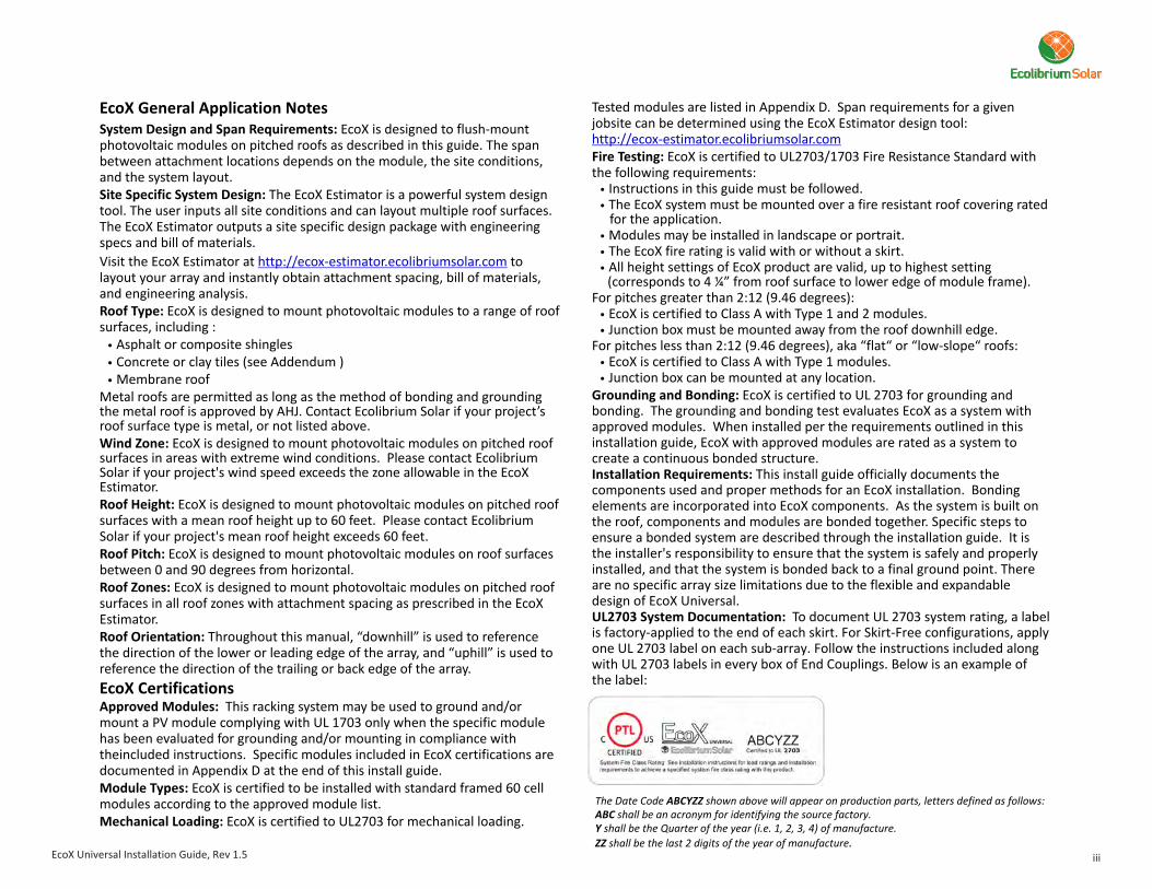
Tested modules are listed in Appendix D. Span requirements for a given jobsite can be determined using the EcoX Estimator design tool:
Fire Testing: EcoX is certified to UL2703/1703 Fire Resistance Standard with the following requirements:
l Instructions in this guide must be followed.l The EcoX system must be mounted over a fire resistant roof covering rated
for the application.l Modules may be installed in landscape or portrait.l The EcoX fire rating is valid with or without a skirt.l All height settings of EcoX product are valid, up to highest setting
(corresponds to 4 ¼” from roof surface to lower edge of module frame).For pitches greater than 2:12 (9.46 degrees):
l EcoX is certified to Class A with Type 1 and 2 modules.l Junction box must be mounted away from the roof downhill edge.
For pitches less than 2:12 (9.46 degrees), aka “flat“ or “low-slope“ roofs:l EcoX is certified to Class A with Type 1 modules.l Junction box can be mounted at any location.
Grounding and Bonding: EcoX is certified to UL 2703 for grounding and bonding. The grounding and bonding test evaluates EcoX as a system with approved modules. When installed per the requirements outlined in this installation guide, EcoX with approved modules are rated as a system to create a continuous bonded structure. Installation Requirements: This install guide officially documents the components used and proper methods for an EcoX installation. Bonding elements are incorporated into EcoX components. As the system is built on the roof, components and modules are bonded together. Specific steps to ensure a bonded system are described through the installation guide. It is the installer's responsibility to ensure that the system is safely and properly installed, and that the system is bonded back to a final ground point. There are no specific array size limitations due to the flexible and expandable design of EcoX Universal.UL2703 System Documentation: To document UL 2703 system rating, a label is factory-applied to the end of each skirt. For Skirt-Free configurations, apply one UL 2703 label on each sub-array. Follow the instructions included along with UL 2703 labels in every box of End Couplings. Below is an example of the label:
The Date Code ABCYZZ shown above will appear on production parts, letters defined as follows:ABC shall be an acronym for identifying the source factory.Y shall be the Quarter of the year (i.e. 1, 2, 3, 4) of manufacture.
ZZ shall be the last 2 digits of the year of manufacture.
http://ecox-estimator.ecolibriumsolar.com
EcoX General Application NotesSystem Design and Span Requirements: EcoX is designed to flush-mount photovoltaic modules on pitched roofs as described in this guide. The span between attachment locations depends on the module, the site conditions, and the system layout. Site Specific System Design: The EcoX Estimator is a powerful system design tool. The user inputs all site conditions and can layout multiple roof surfaces. The EcoX Estimator outputs a site specific design package with engineering specs and bill of materials.Visit the EcoX Estimator at to layout your array and instantly obtain attachment spacing, bill of materials, and engineering analysis.Roof Type: EcoX is designed to mount photovoltaic modules to a range of roof surfaces, including :
Asphalt or composite shinglesConcrete or clay tiles (see Addendum )Membrane roof
Metal roofs are permitted as long as the method of bonding and grounding the metal roof is approved by AHJ. Contact Ecolibrium Solar if your project’s roof surface type is metal, or not listed above.Wind Zone: EcoX is designed to mount photovoltaic modules on pitched roof surfaces in areas with extreme wind conditions. Please contact Ecolibrium Solar if your project's wind speed exceeds the zone allowable in the EcoX Estimator.Roof Height: EcoX is designed to mount photovoltaic modules on pitched roof surfaces with a mean roof height up to 60 feet. Please contact Ecolibrium Solar if your project's mean roof height exceeds 60 feet.Roof Pitch: EcoX is designed to mount photovoltaic modules on roof surfaces between 0 and 90 degrees from horizontal.Roof Zones: EcoX is designed to mount photovoltaic modules on pitched roof surfaces in all roof zones with attachment spacing as prescribed in the EcoX Estimator.Roof Orientation: Throughout this manual, “downhill” is used to reference the direction of the lower or leading edge of the array, and “uphill” is used to reference the direction of the trailing or back edge of the array.EcoX CertificationsApproved Modules: This racking system may be used to ground and/or mount a PV module complying with UL 1703 only when the specific module has been evaluated for grounding and/or mounting in compliance with theincluded instructions. Specific modules included in EcoX certifications are documented in Appendix D at the end of this install guide.Module Types: EcoX is certified to be installed with standard framed 60 cell modules according to the approved module list. Mechanical Loading: EcoX is certified to UL2703 for mechanical loading.
http://ecox-estimator.ecolibriumsolar.com
l
l
l
EcoX Universal Installation Guide, Rev 1.5
EcoX Universal Installation Guide, Rev 1.5
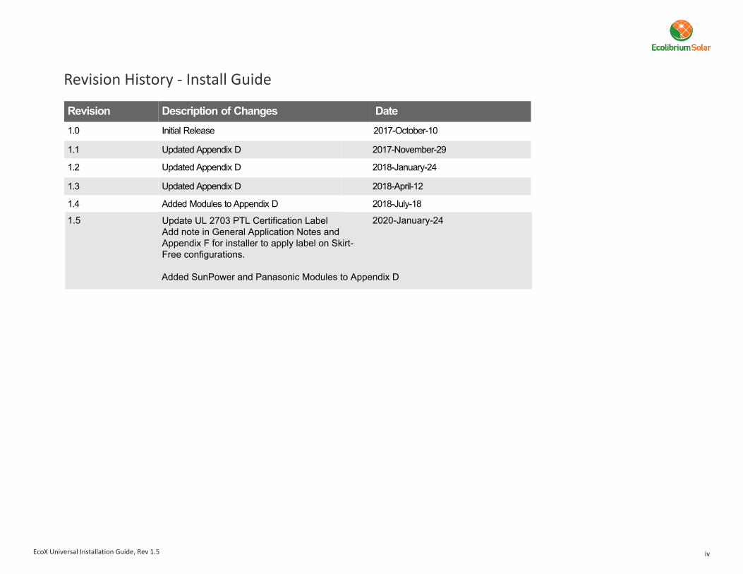
Revision History - Install Guide
iv
Revision Description of Changes Date
1.0 Initial Release 2017-October-10
1.1 Updated Appendix D 2017-November-29
1.2 Updated Appendix D 2018-January-24
1.3 Updated Appendix D 2018-April-12
1.4 Added Modules to Appendix D 2018-July-18
1.5 Update UL 2703 PTL Certification Label Add note in General Application Notes and Appendix F for installer to apply label on Skirt-Free configurations.
Added SunPower and Panasonic Modules to Appendix D
2020-January-24

Dovetail Engagement(mates to Base)
Dovetail Engagement(mates to Spacer)
Glider
Strut Nut
Serrated Strut Bolt
Bonding Clip(not visible)
Lower Clamp(tongue supportsdownhill edge of Module)
Upper Clamp
EcoX Universal ComponentsAttachment Kit
Coupling Assembly
Clamp Assembly
Skirts & Spacers Skirts are used on the first downhill row to enhance the appearance along the edge of the array. Spacers (one per Clamp, two per Coupling) position Skirt to accommodate module frame thickness. Spacers are available in six Module thicknesses ranging from 32mm through 46mm.
Vertical Tab Engages Spacers securing Skirt to Clamp Assemblies and Couplings.Skirts are factory cut to length to match specific Modules.
l
l
See Appendix G for skirt-less installation details.
The Clamp Assembly is mounted to the Base of the Attachment Kit.
Upper and Lower Clamp secures edges of Modules Upper and Lower Clamp engage Skirt on Skirt row.On the first downhill row, Clamps secure module-specific Spacer to position Skirt. Strut Bolt and Strut Nut secure Clamp Assembly to Base and Modules to Clamp Assembly.Factory installed Bond Clip bonds Skirt to Attachment Kit on south row, and Module to Attachment Kit on subsequent rows.
l
l
l
l
l
The Attachment Kit is secured to the roof and supports the array via the Clamp Assembly.Its features include:
Grooves along sides of Base are Dovetail Engagements which provide adjustability of the Clamp Assembly in height and uphill-downhill directions.Base is attached via a single Lag Screw.Lag Screw includes a factory pre-installed Sealing Washer.
l
l
l
Torque Spec: 14 ft-lbs
Couplings connect up to four Modules together.
Couplings include indicator marks to set a 1/2" gap between Modules.On the first downhill row, Couplings and module-specific Spacers secure Skirts at their joint, while positioning the Skirt to accommodate module frame thickness. Factory installed Bond Clips (two per Coupling) bond Modules left and right.
l
l
l
Torque Spec: 14 ft-lbs
Flashing
Torque Spec: 14 ft-lbs
Base
Skirt
Dovetail Engagements(mates to Glider)
5/16" Lag Screwwith Sealing Washer
Dovetail Engagement(mates to Spacer)
SerratedHex Bolts
Bonding Clip(not visible)
Bonding Clip(not visible)
Lower Clamp(tongue supportsdownhill edge of Modules)
Upper Clamp
Alignment Indicators
Spacer
Vertical Tab
1 of 31EcoX Universal Installation Guide, Rev 1.5
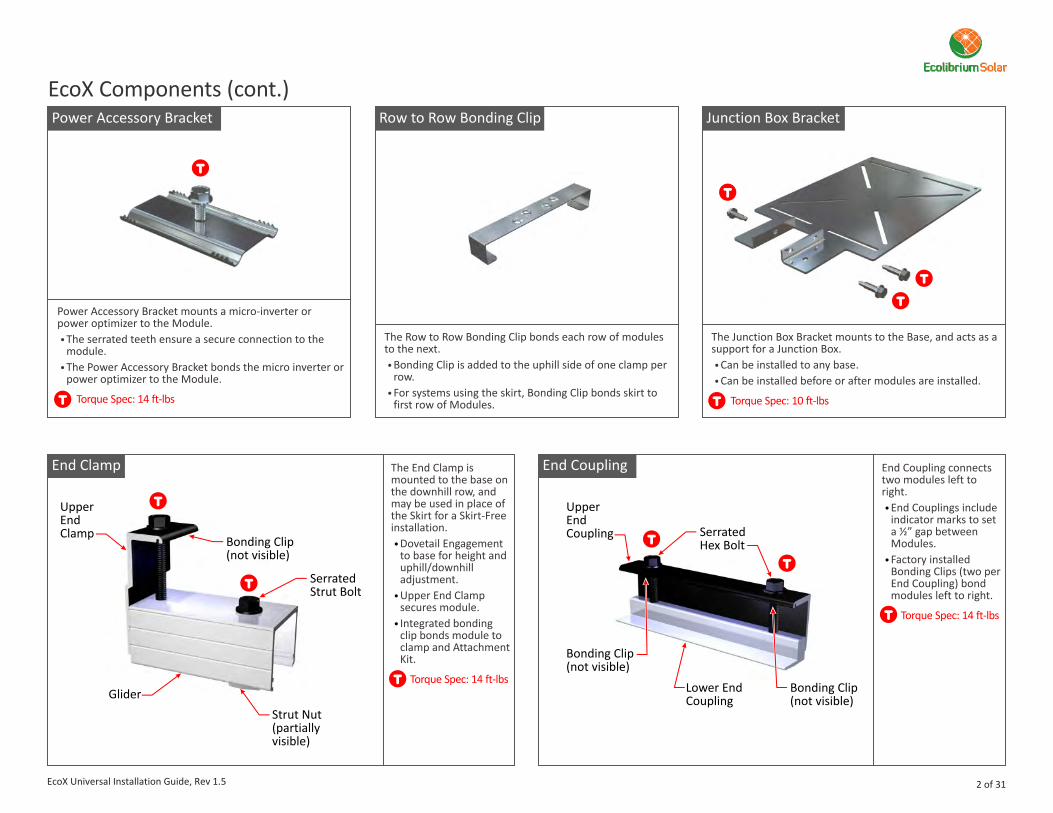
EcoX Components (cont.)Power Accessory Bracket Junction Box BracketRow to Row Bonding Clip
End CouplingEnd Clamp End Coupling connects two modules left to right.
End Couplings include indicator marks to set a ½” gap between Modules.Factory installed Bonding Clips (two per End Coupling) bond modules left to right.
l
l
Torque Spec: 14 ft-lbs
The End Clamp is mounted to the base on the downhill row, and may be used in place of the Skirt for a Skirt-Free installation.
Dovetail Engagement to base for height and uphill/downhill adjustment.Upper End Clamp secures module.Integrated bonding clip bonds module to clamp and Attachment Kit.
l
l
l
Torque Spec: 14 ft-lbs
Power Accessory Bracket mounts a micro-inverter or power optimizer to the Module. l The serrated teeth ensure a secure connection to the
module.l The Power Accessory Bracket bonds the micro inverter or
power optimizer to the Module.
Torque Spec: 14 ft-lbs
The Junction Box Bracket mounts to the Base, and acts as a support for a Junction Box.l Can be installed to any base.l Can be installed before or after modules are installed.
Torque Spec: 10 ft-lbs
The Row to Row Bonding Clip bonds each row of modules to the next.l Bonding Clip is added to the uphill side of one clamp per
row.l For systems using the skirt, Bonding Clip bonds skirt to
first row of Modules.
GliderStrut Nut(partiallyvisible)
Serrated Strut Bolt
Serrated Hex Bolt
UpperEndCoupling
Lower EndCoupling
Upper EndClamp
Bonding Clip(not visible)
Bonding Clip(not visible)
Bonding Clip(not visible)
2 of 31EcoX Universal Installation Guide, Rev 1.5
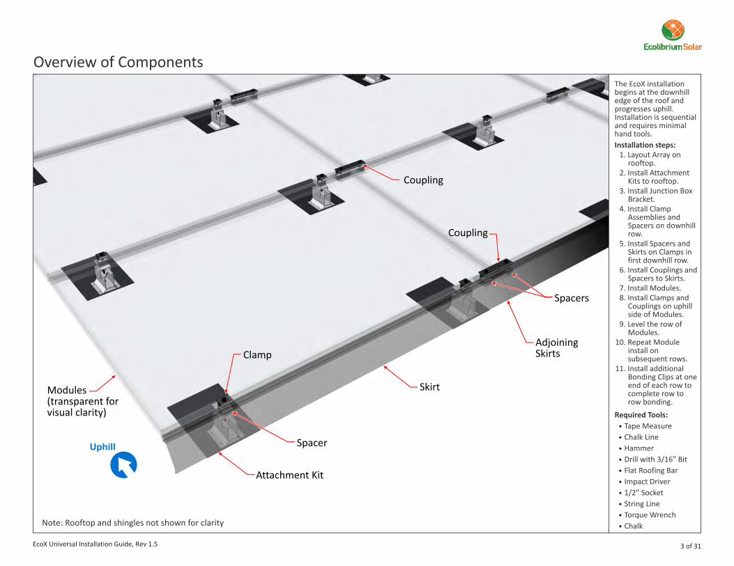
The EcoX installation begins at the downhill edge of the roof and progresses uphill. Installation is sequential and requires minimal hand tools.Installation steps:
1. Layout Array onrooftop.
2. Install AttachmentKits to rooftop.
3. Install Junction BoxBracket.
4. Install ClampAssemblies andSpacers on downhillrow.
5. Install Spacers andSkirts on Clamps infirst downhill row.
6. Install Couplings andSpacers to Skirts.
7. Install Modules.8. Install Clamps and
Couplings on uphillside of Modules.
9. Level the row ofModules.
10. Repeat Moduleinstall onsubsequent rows.
11. Install additionalBonding Clips at oneend of each row tocomplete row torow bonding.
Required Tools:
Tape MeasureChalk LineHammerDrill with 3/16" BitFlat Roofing BarImpact Driver1/2" SocketString LineTorque WrenchChalk
l
l
l
l
l
l
l
l
l
l
Overview of Components
Note: Rooftop and shingles not shown for clarity
Attachment Kit
Spacer
Spacers
Clamp
Coupling
Coupling
Skirt
AdjoiningSkirts
Modules (transparent for visual clarity)
3 of 31EcoX Universal Installation Guide, Rev 1.5
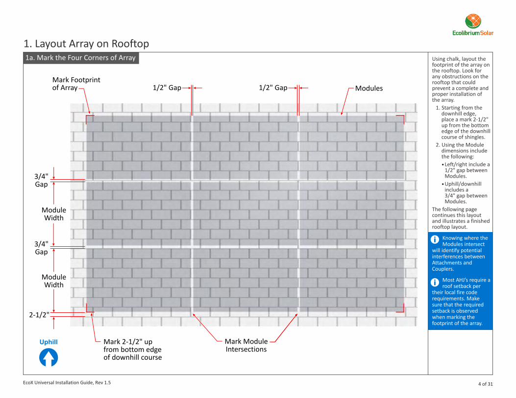
1. Layout Array on RooftopUsing chalk, layout the footprint of the array on the rooftop. Look for any obstructions on the rooftop that could prevent a complete and proper installation of the array.
1. Starting from thedownhill edge,place a mark 2-1/2"up from the bottomedge of the downhillcourse of shingles.
2. Using the Moduledimensions includethe following:
Left/right include a1/2" gap betweenModules.Uphill/downhillincludes a3/4" gap betweenModules.
The following page continues this layout and illustrates a finished rooftop layout.
l
l
Knowing where the Modules intersect
will identify potential interferences between Attachments and Couplers.
Most AHJ’s require a roof setback per
their local fire code requirements. Make sure that the required setback is observed when marking the footprint of the array.
1a. Mark the Four Corners of Array
Mark ModuleIntersections
Mark Footprintof Array Modules
Mark 2-1/2" up from bottom edge of downhill course
2-1/2"
3/4"Gap
3/4"Gap
1/2" Gap 1/2" Gap
ModuleWidth
ModuleWidth
4 of 31EcoX Universal Installation Guide, Rev 1.5

1. Snap left/right chalklines.
2. Mark theattachmentlocations by locatingthe structuralmembers of theroof. Refer to theEcoX Calculator formaximum allowablespan and cantilever.
Ensure that attachment
locations meet and do not exceed, the EcoX design specifications on allowable spans and cantilever distances.
When marking the attachment
locations, make the downhill leg of the mark long enough to be visible from the downhill edge of the Flashing when the Flashing is in its installed position. This mark will accelerate the Flashing installation by quick alignment of the Flashing to the mark.
1b. Snapping Chalk Lines and Marking Attachment Locations
Cornersof Array
Make thesemarks extra long downhill. See
Roof Structural Members Attachment Locations
1. Layout Array on Rooftop (cont.)
Cantilever Span
5 of 31EcoX Universal Installation Guide, Rev 1.5
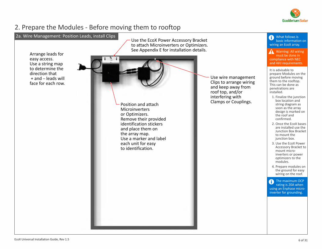
What follows is basic information on
wiring an EcoX array.
Warning: All wiring must be done in
compliance with NEC and AHJ requirements.
The maximum OCP rating is 20A when
using an Enphase micro-inverter for grounding.
It is advisable to prepare Modules on the ground before moving them to the rooftop. This can be done as penetrations are installed.
1. Finalize the junctionbox location andstring diagram assoon as the arraydesign is marked onthe roof andconfirmed.
2. Once the EcoX basesare installed use theJunction Box Bracketto mount thejunction box.
3. Use the EcoX PowerAccessory Bracket tomount micro-inverters or poweroptimizers to themodules.
4. Prepare modules onthe ground for easywiring on the roof.
2a. Wire Management: Position Leads, install Clips
2. Prepare the Modules - Before moving them to rooftop
Position and attach Microinvertersor Optimizers.Remove their provided identification stickers and place them on the array map. Use a marker and label each unit for easy to identification.
Use wire managementClips to arrange wiringand keep away fromroof top, and/or interfering with Clamps or Couplings.
Use the EcoX Power Accessory Bracketto attach Microinverters or Optimizers.See Appendix E for installation details.
Arrange leads for easy access.Use a string mapto determine the direction that + and leads will face for each row.
–
6 of 31EcoX Universal Installation Guide, Rev 1.5
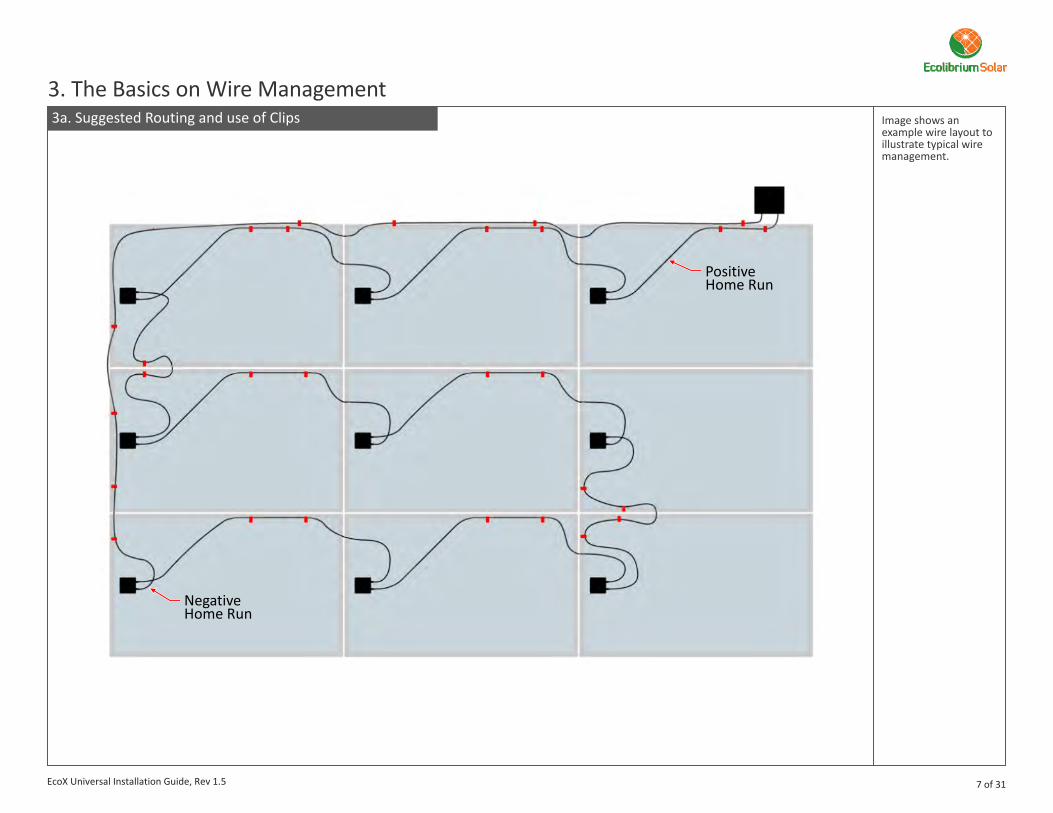
Image shows an example wire layout to illustrate typical wire management.
3a. Suggested Routing and use of Clips
3. The Basics on Wire Management
PositiveHome Run
NegativeHome Run
7 of 31EcoX Universal Installation Guide, Rev 1.5
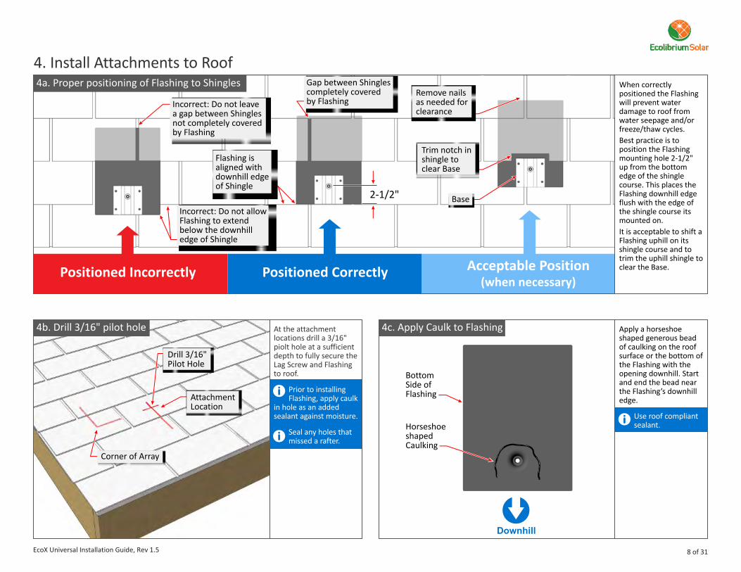
4a. Proper positioning of Flashing to Shingles
1a 1a Apply a horseshoe shaped generous bead of caulking on the roof surface or the bottom of the Flashing with the opening downhill. Start and end the bead near the Flashing’s downhill edge.
Use roof compliant sealant.
When correctly positioned the Flashing will prevent water damage to roof from water seepage and/or freeze/thaw cycles.Best practice is to position the Flashing mounting hole 2-1/2" up from the bottom edge of the shingle course. This places the Flashing downhill edge flush with the edge of the shingle course its mounted on.It is acceptable to shift a Flashing uphill on its shingle course and to trim the uphill shingle to clear the Base.Positioned Incorrectly Positioned Correctly Acceptable
(when necessary)Position
2-1/2"
4. Install Attachments to Roof
4b. Drill 3/16" pilot hole 4c. Apply Caulk to FlashingAt the attachment locations drill a 3/16" piolt hole at a sufficient depth to fully secure the Lag Screw and Flashing to roof.
Prior to installing Flashing, apply caulk
in hole as an added sealant against moisture.
Seal any holes that missed a rafter.
Horseshoe shapedCaulking
BottomSide ofFlashingAttachment
Location
Drill 3/16" Pilot Hole
Corner of Array
Flashing isaligned withdownhill edgeof Shingle
Incorrect: Do not allowFlashing to extendbelow the downhilledge of Shingle
Incorrect: Do not leavea gap between Shinglesnot completely coveredby Flashing
Gap between Shinglescompletely covered by Flashing
Remove nailsas needed forclearance
Trim notch in shingle to clear Base
Base
Downhill
8 of 31EcoX Universal Installation Guide, Rev 1.5
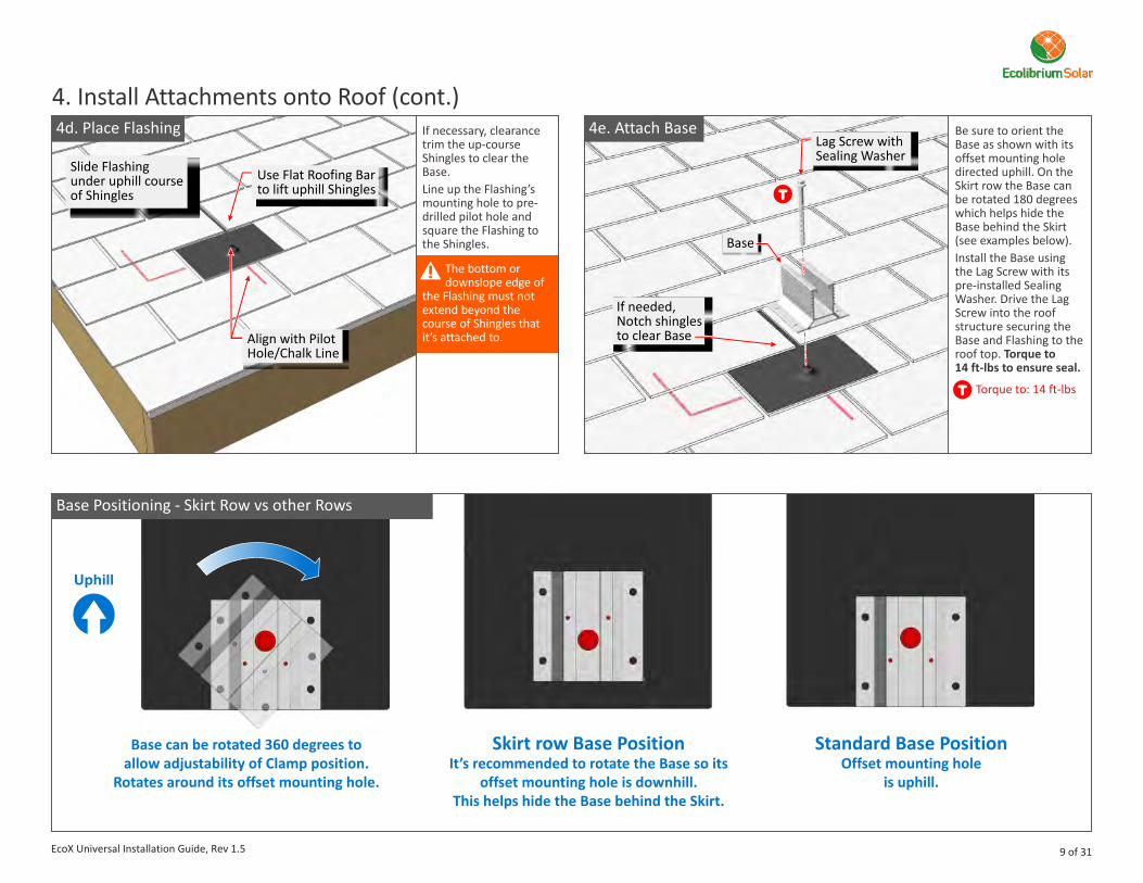
Be sure to orient the Base as shown with its offset mounting hole directed uphill. On the Skirt row the Base can be rotated 180 degrees which helps hide the Base behind the Skirt (see examples below).Install the Base using the Lag Screw with its pre-installed Sealing Washer. Drive the Lag Screw into the roof structure securing the Base and Flashing to the roof top. Torque to 14 ft-lbs to ensure seal.
Torque to: 14 ft-lbs
If necessary, clearance trim the up-course Shingles to clear the Base.Line up the Flashing’s mounting hole to pre-drilled pilot hole and square the Flashing to the Shingles.
The bottom or downslope edge of
the Flashing must not extend beyond the course of Shingles that it’s attached to.
4d. Place Flashing
4. Install Attachments onto Roof (cont.)
Slide Flashing under uphill course of Shingles
Use Flat Roofing Barto lift uphill Shingles
Align with Pilot Hole/Chalk Line
Lag Screw with Sealing Washer
If needed, Notch shingles to clear Base
Base
4e. Attach Base
Base can be rotated 360 degrees to allow adjustability of Clamp position.
Rotates around its offset mounting hole.
Skirt row Base PositionIt’s recommended to rotate the Base so its
offset mounting hole is downhill. This helps hide the Base behind the Skirt.
Standard Base PositionOffset mounting hole
is uphill.
Base Positioning - Skirt Row vs other Rows
9 of 31EcoX Universal Installation Guide, Rev 1.5
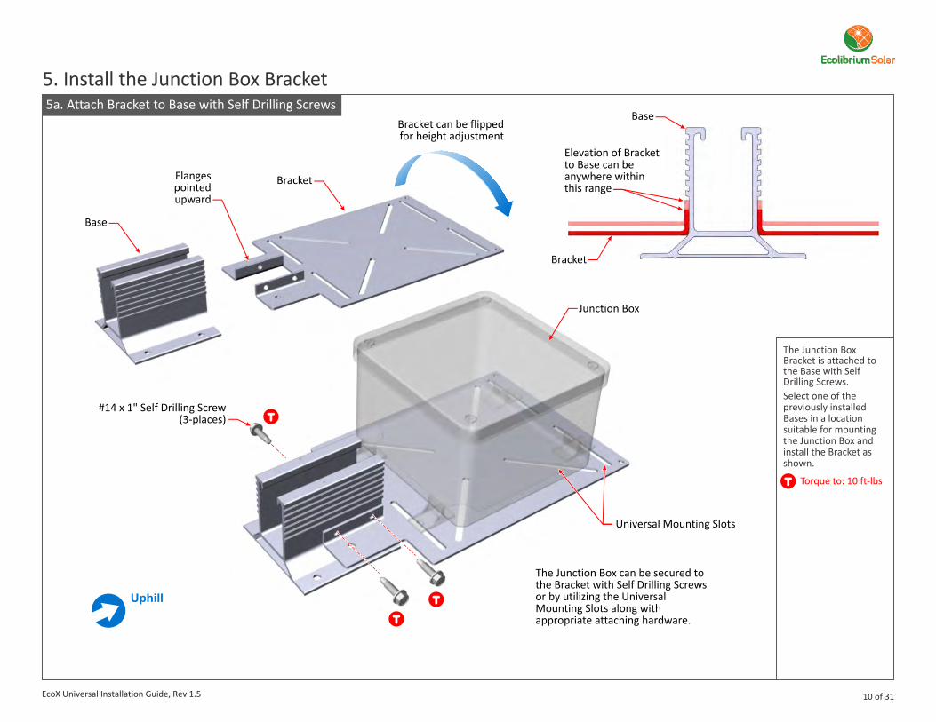
5. Install the Junction Box Bracket5a. Attach Bracket to Base with Self Drilling Screws
Base
Bracket
Bracket can be flippedfor height adjustment
Flanges pointed upward
Bracket
Universal Mounting Slots
#14 x 1" Self Drilling Screw(3-places)
Base
Elevation of Bracket to Base can be anywhere within this range
Junction Box
The Junction Box can be secured to the Bracket with Self Drilling Screws or by utilizing the Universal Mounting Slots along with appropriate attaching hardware.
The Junction Box Bracket is attached to the Base with Self Drilling Screws.Select one of the previously installed Bases in a location suitable for mounting the Junction Box and install the Bracket as shown.
Torque to: 10 ft-lbs
10 of 31EcoX Universal Installation Guide, Rev 1.5
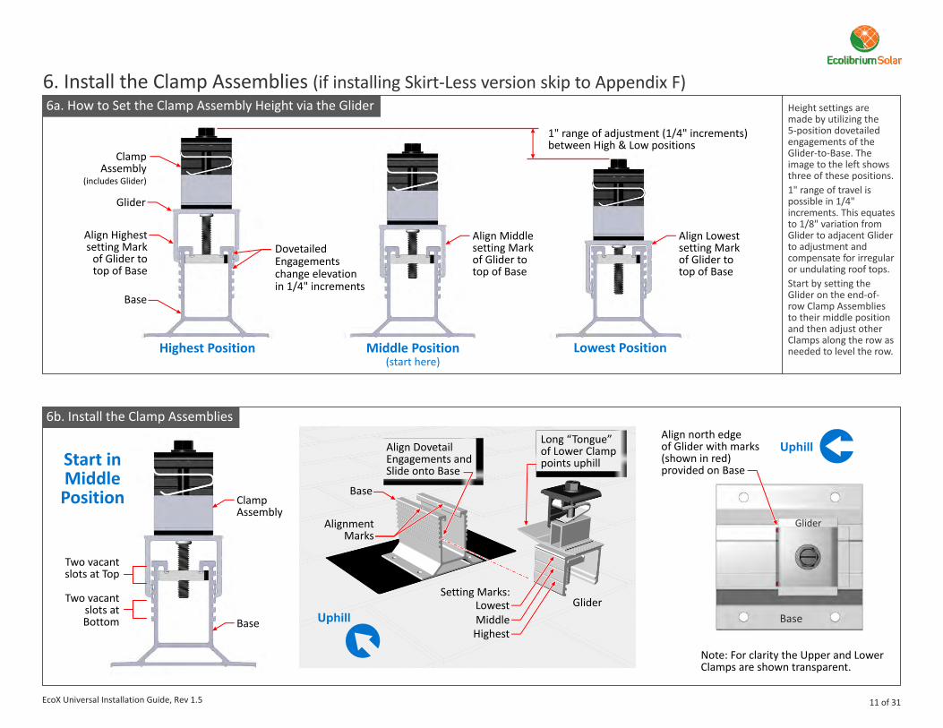
Height settings are made by utilizing the 5-position dovetailedengagements of theGlider-to-Base. Theimage to the left showsthree of these positions.1" range of travel is possible in 1/4" increments. This equates to 1/8" variation from Glider to adjacent Glider to adjustment and compensate for irregular or undulating roof tops.Start by setting the Glider on the end-of-row Clamp Assemblies to their middle position and then adjust other Clamps along the row as needed to level the row.
6. Install the Clamp Assemblies (if installing Skirt-Less version skip to Appendix F)6a. How to Clamp Assembly Height via the GliderSet the
Highest Position Middle Position(start here)
Lowest Position
DovetailedEngagementschange elevationin 1/4" increments
Glider
Align Highest setting Mark
of Glider to top of Base
Align Middle setting Mark of Glider to top of Base
Align Lowest setting Mark of Glider to top of Base
1" range of adjustment (1/4" increments)between High & Low positions
ClampAssembly
(includes Glider)
Base
6b. Install the Clamp Assemblies
Glider
Align north edge of Glider with marks (shown in red)provided on Base
LowestSetting Marks:
MiddleHighest
Glider
Note: For clarity the Upper and Lower Clamps are shown transparent.
Base
Base
AlignmentMarks
Base
ClampAssembly
Align DovetailEngagements andSlide onto Base
Long “Tongue” of Lower Clamp points uphill
Two vacant slots at Top
Two vacant slots at Bottom
Start in Middle Position
11 of 31EcoX Universal Installation Guide, Rev 1.5

Use an impact driver to tighten the Strut Bolt and engage the Strut Nut channels with the two flanges of the Base. Leave the Clamp open to accept the Module. The Leaf Spring provides pressure to keep the Strut Nut engaged and in-position while the installation continues.Further tightening will be done as the Modules are installed.
Do not over tighten the Clamps on the
Skirt row. They need to be open enough to accept the Skirts. All non-Skirt row Clamps will be tightened as they are installed.
6c. Engage Strut Nut with Base
Strut Bolt
Strut Nut
Note: For Skirt row Clamp installation only.
Flanges
LeafSpring
Channels
6. Install Clamp Assemblies (cont.)A String Line is used to level and align Clamp Assemblies on the first downhill row only.The body of the Glider includes one “String Groove” specifically designed to assist with this process.Run and secure the String Line between the two outermost left/right Clamp Assemblies. Place String on the top String Grooves, pulling it taught and securing its ends.
7. Level and Align Clamp Assemblies on Southern Row7a. Run a E-W String Line
String Groove
Align outermostleft/right Gliders with Marks on Bases
Base rotated; its offsetmounting hole is downhillto accommodate Skirt
Run String on uphill side of Clamp AssemblyPosition String
on top groove of the twooutermost left/right Clamp Assemblies
12 of 31EcoX Universal Installation Guide, Rev 1.5

7. Level and Align Clamp Assemblies (cont.)7b. Level and Align to String Line
Left Clamp Assembly
Right Clamp Assembly
String Line
String Line
Problem:Top Groove not aligned with String Line
Solution:Raise Glider one Dovetail Engagement (1/4") to align Top Groove of Glider with StringBase
StringGroove(Top Groove)
Height Adjustments
13 of 31
Uphill/Downhill Adjustments
String Line
Gap
Problem:Gap too largebetween String Line and Glider
Solution:
sliding GliderToward Stringleaving a gap of 1/16" or less
Reduce gap by
String Line
EcoX Universal Installation Guide, Rev 1.5
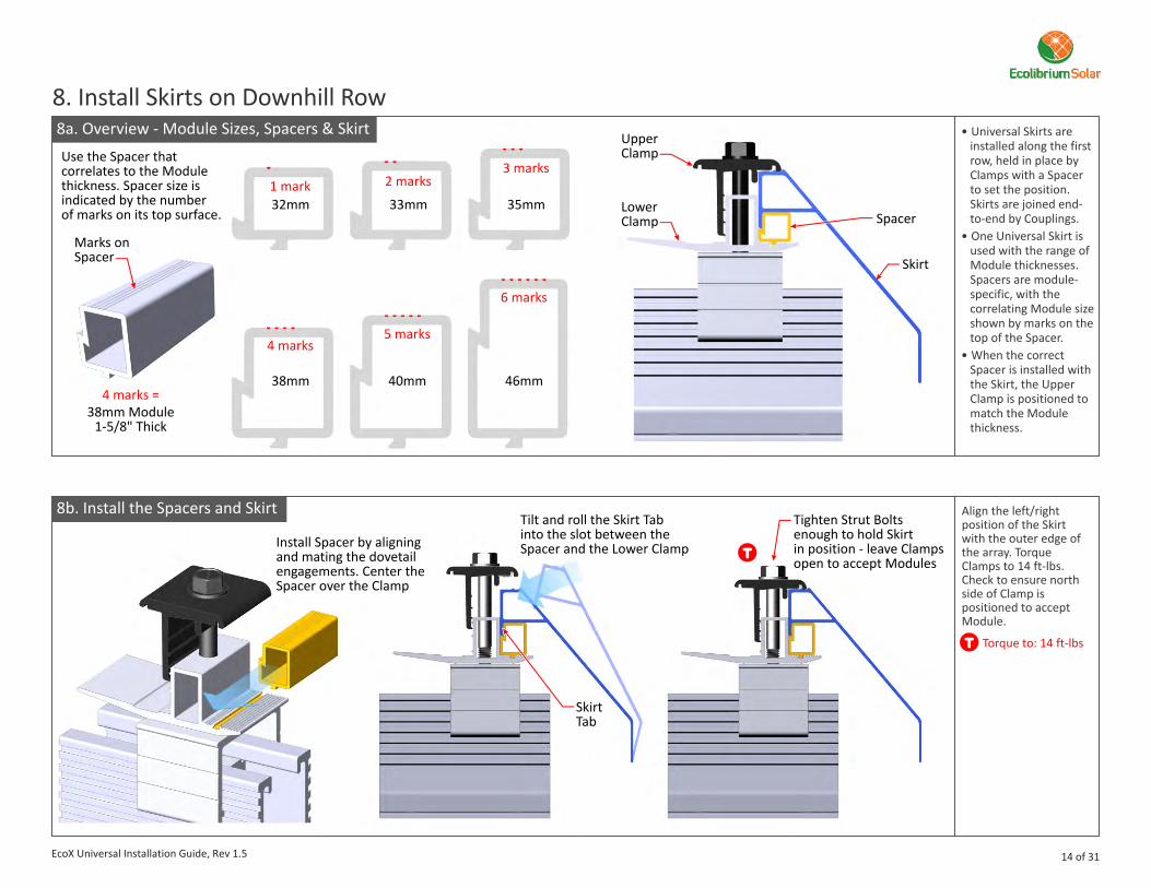
Align the left/right position of the Skirt with the outer edge of the array. Torque Clamps to 14 ft-lbs. Check to ensure north side of Clamp is positioned to accept Module.
Torque to: 14 ft-lbs
8. Install Skirts on Downhill Row8a. Overview - Module Sizes, Spacers & Skirt
8b. Install the Spacers and Skirt
l Universal Skirts areinstalled along the first row, held in place by Clamps with a Spacer to set the position. Skirts are joined end-to-end by Couplings.
l One Universal Skirt isused with the range ofModule thicknesses.Spacers are module-specific, with thecorrelating Module sizeshown by marks on thetop of the Spacer.
l When the correctSpacer is installed withthe Skirt, the UpperClamp is positioned tomatch the Modulethickness.
Spacer
Skirt
Skirt Tab
UpperClamp
LowerClamp
Install Spacer by aligning and mating the dovetail engagements. Center the Spacer over the Clamp
Tilt and roll the Skirt Tab into the slot between the Spacer and the Lower Clamp
Use the Spacer that correlates to the Module thickness. Spacer size isindicated by the number of marks on its top surface.
Marks on Spacer
32mm1 mark
38mm
38mm Module1-5/8" Thick
4 marks
4 marks =
33mm
2 marks
40mm
5 marks
35mm
3 marks
46mm
6 marks
Tighten Strut Bolts enough to hold Skirt in position - leave Clamps open to accept Modules
14 of 31EcoX Universal Installation Guide, Rev 1.5
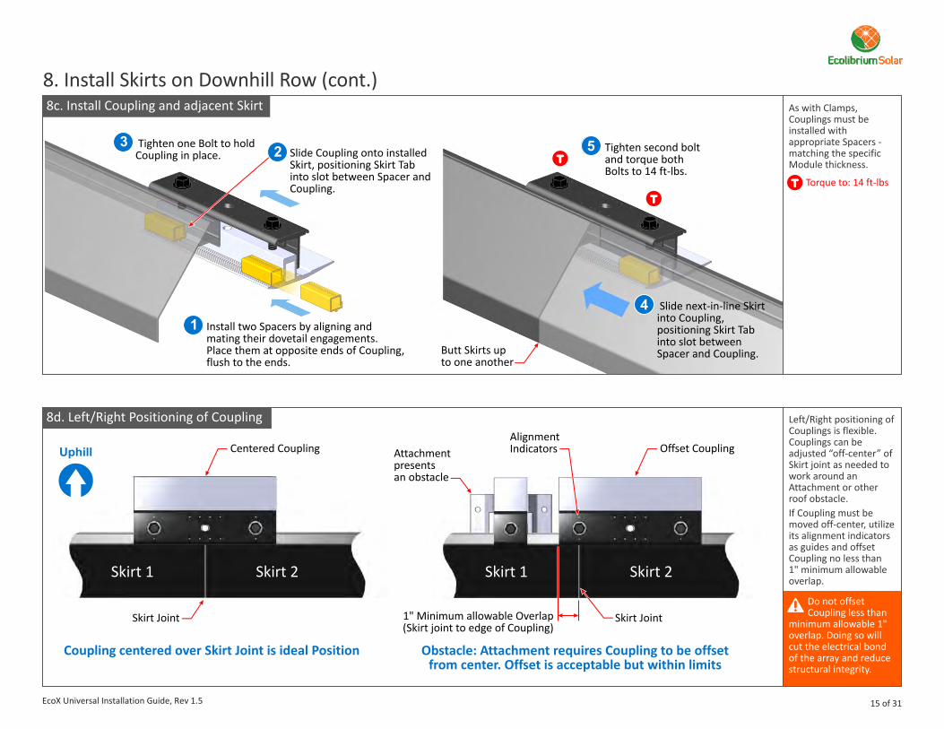
Left/Right positioning of Couplings is flexible. Couplings can be adjusted “off-center” of Skirt joint as needed to work around an Attachment or other roof obstacle.If Coupling must be moved off-center, utilize its alignment indicators as guides and offset Coupling no less than 1" minimum allowable overlap.
Do not offset Coupling less than
minimum allowable 1" overlap. Doing so will cut the electrical bond of the array and reduce structural integrity.
8. Install Skirts on Downhill Row (cont.)8c. Install Coupling and adjacent Skirt
8d. Left/Right Positioning of Coupling
As with Clamps, Couplings must be installed with appropriate Spacers - matching the specific Module thickness.
Torque to: 14 ft-lbs
Coupling centered over Skirt Joint is ideal Position Obstacle: Attachment requires Coupling to be offset from center. Offset is acceptable but within limits
Attachment presentsan obstacle
AlignmentIndicators
Skirt Joint Skirt Joint
Offset CouplingCentered Coupling
1" Minimum allowable Overlap(Skirt joint to edge of Coupling)
Skirt 2Skirt 2 Skirt 1Skirt 1
15 of 31
Butt Skirts upto one another
Slide Coupling onto installed Skirt, positioning Skirt Tab into slot between Spacer and Coupling.
Install two Spacers by aligning and mating their dovetail engagements. Place them at opposite ends of Coupling, flush to the ends.
Tighten one Bolt to hold Coupling in place.
Slide next-in-line Skirt into Coupling, positioning Skirt Tab into slot between Spacer and Coupling.
Tighten second bolt and torque both Bolts to 14 ft-lbs.
1
23
4
5
EcoX Universal Installation Guide, Rev 1.5
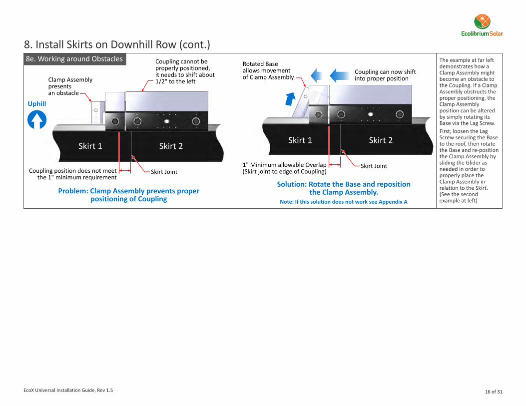
8. Install Skirts on Downhill Row (cont.)The example at far left demonstrates how a Clamp Assembly might become an obstacle to the Coupling. If a Clamp Assembly obstructs the proper positioning, the Clamp Assembly position can be altered by simply rotating its Base via the Lag Screw.First, loosen the Lag Screw securing the Base to the roof, then rotate the Base and re-position the Clamp Assembly by sliding the Glider as needed in order to properly place the Clamp Assembly in relation to the Skirt. (See the second example at left)
Problem: Clamp Assembly prevents properpositioning of Coupling
Solution: Rotate the Base and repositionthe Clamp Assembly.
Clamp Assemblypresentsan obstacle
Rotated Baseallows movementof Clamp Assembly
8e. Working around Obstacles
Skirt Joint
Coupling cannot be properly positioned,it needs to shift about 1/2" to the left
Coupling can now shiftinto proper position
Coupling position does not meet the 1" minimum requirement
Skirt 2Skirt 1
Skirt Joint1" Minimum allowable Overlap(Skirt joint to edge of Coupling)
Skirt 2Skirt 1
Note: If this solution does not work see Appendix A
16 of 31EcoX Universal Installation Guide, Rev 1.5

9. Install Modules9a. Pivot Modules into Clamps & Couplings Hold the module
on its uphill edge, and place its downhill edge onto the Tongue of the Lower Clamps and Coupling of the Skirt Row.
Pivot its uphill edgedownward toward
the Base/Lower Clamps of the uphill row.
Rest the Module on the Base.Be certain that the Module Frame has
fully seated into/against the Clamps and Couplers of the Skirt Row.
Place Module on tonguesof the Lower Clamps and Coupling
Rest Module on uphill Base
Pivot Module downward while pushing it into the Skirt Row Clamp Assembly
1
1
2
2
3
3
Uphill BaseSkirt Row Base & Clamp Assembly
module starting position
module resting position
View looking from left edge
4Ensure that Module is fully seated in Clamp Assembly and Coupling
4
module
17 of 31EcoX Universal Installation Guide, Rev 1.5

9. Install Modules (cont.)9b. Continue installing Modules across Skirt Row
Module Frame
Module FrameAlignment Marks
Coupling
Module Frame
Skirt Row
Skirt
Module
Skirt
Module
1/2" Gap
Working across the Skirt row set the Modules in place while leaving a ½” gap between them. Set the gap by the alignment marks on the Skirt row Coupling(s) and aligning the Module frames to these marks.
As each row of Modules is installed, complete all wiring connections and verify that all wire management clips and wires are properly arranged and off the rooftop before proceeding to the next row of Modules.
Wiring
Install home runs or trunk cable if
necessary as each row of modules is installed.
18 of 31EcoX Universal Installation Guide, Rev 1.5
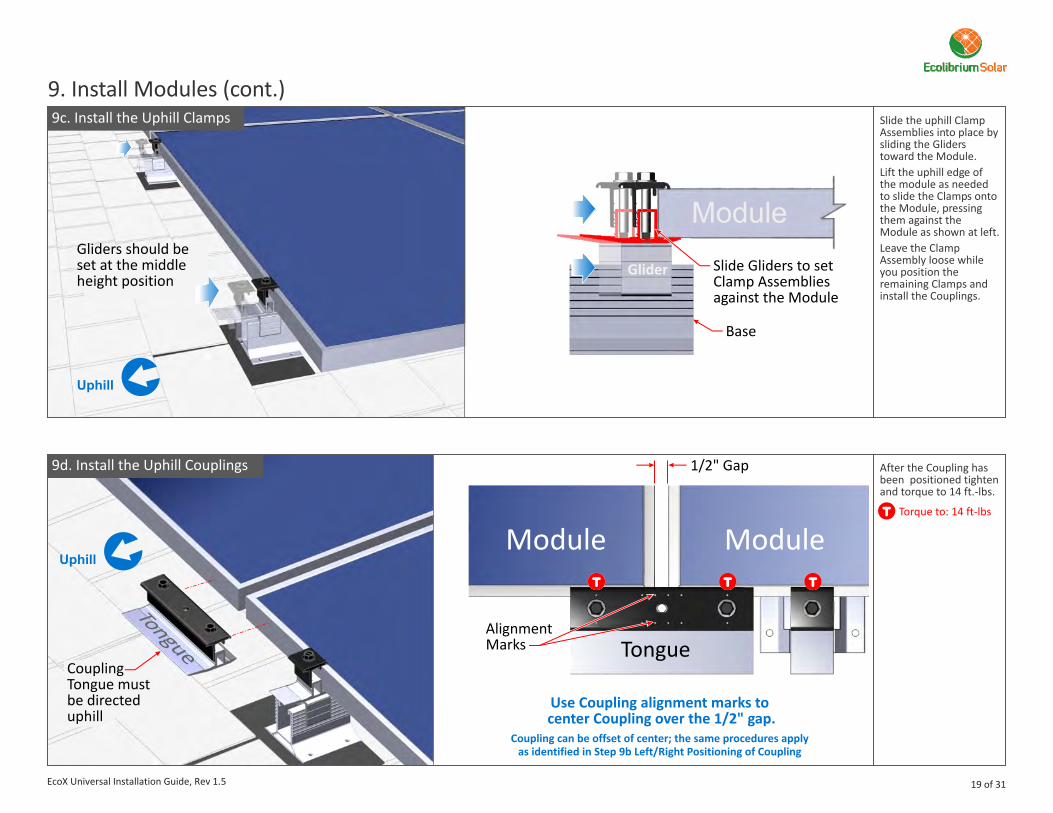
9d. Install the Uphill Couplings After the Coupling has been positioned tighten and torque to 14 ft.-lbs.
Torque to: 14 ft-lbs
Slide the uphill Clamp Assemblies into place by sliding the Gliders toward the Module. Lift the uphill edge of the module as needed to slide the Clamps onto the Module, pressing them against the Module as shown at left.Leave the Clamp Assembly loose while you position the remaining Clamps and install the Couplings.
9c. Install the Uphill Clamps
9. Install Modules (cont.)
Module
Slide Gliders to set Clamp Assembliesagainst the Module
Base
Glider
Module Module
1/2" Gap
Tongue
Use Coupling alignment marks to center Coupling over the 1/2" gap.
Coupling can be offset of center; the same procedures apply as identified in Step 9b Left/Right Positioning of Coupling
Alignment Marks
Gliders should beset at the middle height position
CouplingTongue mustbe directeduphill
19 of 31EcoX Universal Installation Guide, Rev 1.5

9e. Coupling alignment on Modules with Non-Metallic Corners
9. Install Modules (cont.)For Modules that are constructed
with non-metallic corners, ensure the Bonding Clip in the Coupling is fully engaged with the metallic frame of the Module.
When setting the Couplings position on Modules with non-metallic corners, the Couplings left/right range of adjustability is reduced due to the non-metallic area of influence. This area of influence varies by Module make and therefore a close visual inspection must be done to ensure that the Bonding Clip has cleared these areas.
Non-MetallicCorners
Alignment Markplaces Bonding Clip on the non-metallicportion of frame
Alignment Markplaces Bonding Clip on the metallicportion of frame
Incomplete Bond Complete Bond
Module ModuleModule
CouplingCoupling
Note: For clarity the Couplings are shown transparent.
20 of 31EcoX Universal Installation Guide, Rev 1.5
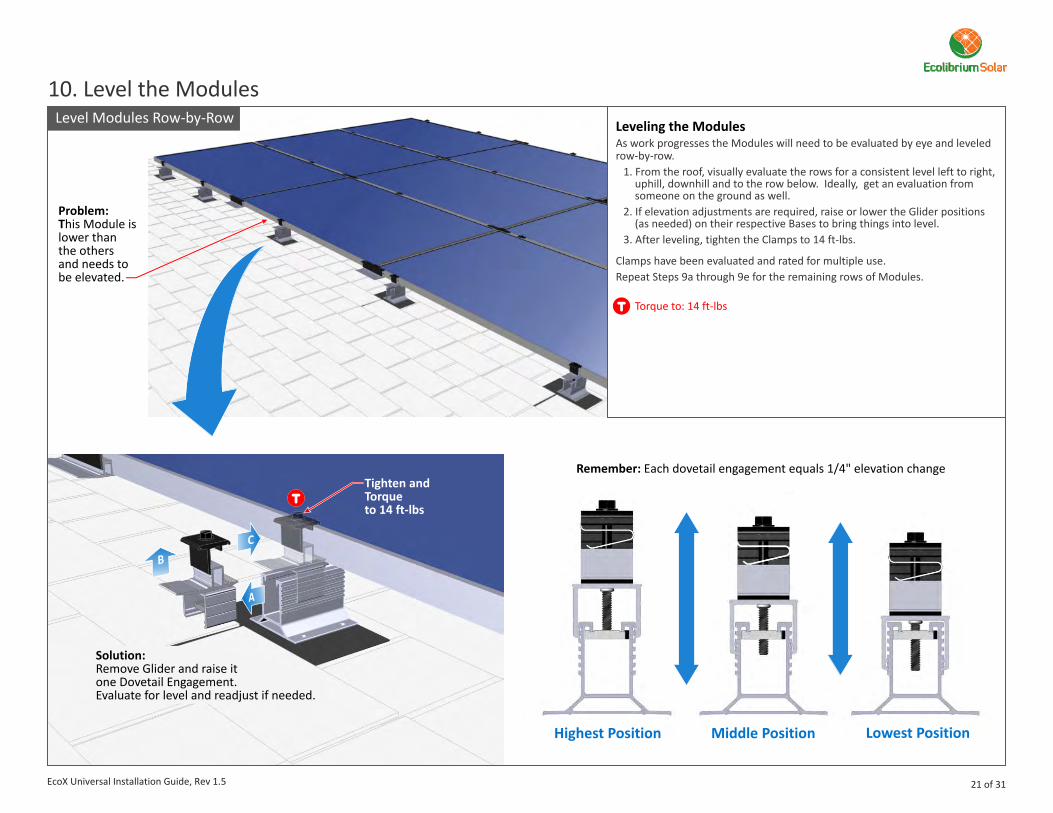
Remember: Each dovetail engagement equals 1/4" elevation change
Highest Position Middle Position Lowest Position
Level Modules Row-by-Row
10. Level the Modules
Problem:This Module is lower thanthe othersand needs to be elevated.
Tighten and Torqueto 14 ft-lbs
Solution:Remove Glider and raise it one Dovetail Engagement.Evaluate for level and readjust if needed.
Leveling the ModulesAs work progresses the Modules will need to be evaluated by eye and leveled row-by-row.
1. From the roof, visually evaluate the rows for a consistent level left to right,uphill, downhill and to the row below. Ideally, get an evaluation fromsomeone on the ground as well.
2. If elevation adjustments are required, raise or lower the Glider positions(as needed) on their respective Bases to bring things into level.
3. After leveling, tighten the Clamps to 14 ft-lbs.
Clamps have been evaluated and rated for multiple use.Repeat Steps 9a through 9e for the remaining rows of Modules.
Torque to: 14 ft-lbs
21 of 31EcoX Universal Installation Guide, Rev 1.5
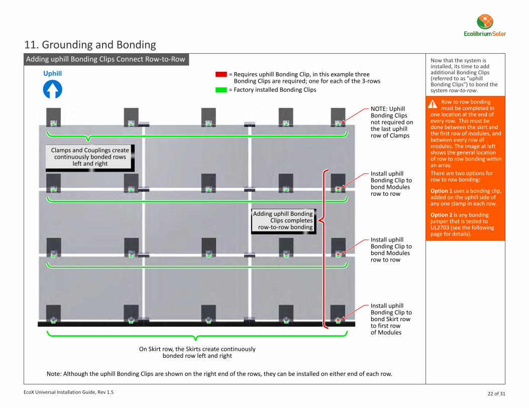
Adding uphill Bonding Clips Connect Row-to-Row
Install uphillBonding Clip tobond Modulesrow to row
NOTE: UphillBonding Clips not required on the last uphillrow of Clamps
Install Bonding Clip tobond Modulesrow to row
uphill
Install Bonding Clip to bond Skirt row to first rowof Modules
uphill
= Requires uphill Bonding Clip, in this example three Bonding Clips are required; one for each of the 3-rows
= Factory installed Bonding Clips
Note: Although the uphill Bonding Clips are shown on the right end of the rows, they can be installed on either end of each row.
11. Grounding and Bonding
Clamps and Couplings create continuously bonded rows
left and right
On Skirt row, the Skirts create continuously bonded row left and right
Now that the system is installed, its time to add additional Bonding Clips (referred to as "uphill Bonding Clips") to bond the system row-to-row.
Row to row bonding must be completed in
one location at the end of every row. This must be done between the skirt and the first row of modules, and between every row of modules. The image at left shows the general location of row to row bonding within an array. There are two options for row to row bonding:
Option 1 uses a bonding clip, added on the uphill side of any one clamp in each row.
Option 2 is any bonding jumper that is tested to UL2703 (see the following page for details).
Adding uphill Bonding Clips completes
row-to-row bonding
22 of 31EcoX Universal Installation Guide, Rev 1.5
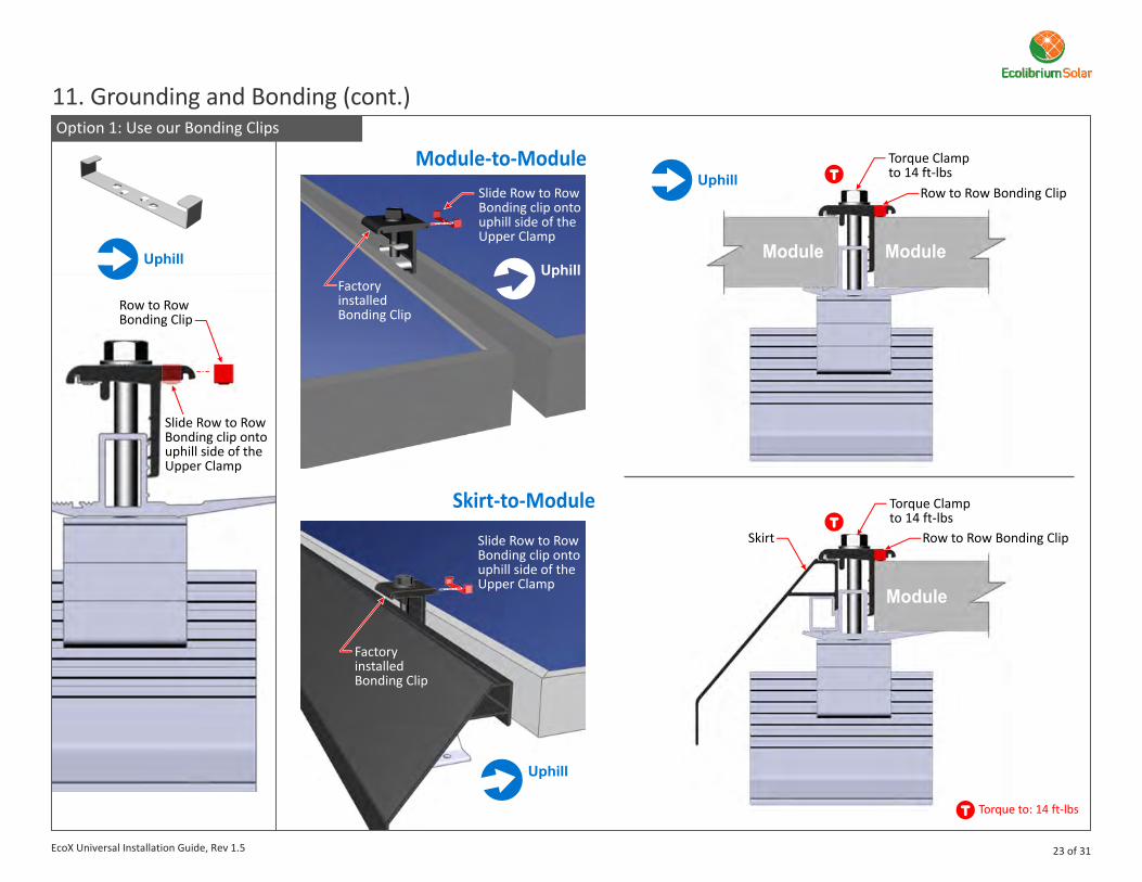
Option 1: Use our Bonding Clips
Torque Clamp to 14 ft-lbs
11. Grounding and Bonding (cont.)
Module Module
Row to RowBonding Clip
Slide Row to RowBonding clip ontouphill side of theUpper Clamp
Slide Row to RowBonding clip ontouphill side of theUpper Clamp
Module-to-Module
Skirt-to-Module
Factory installedBonding Clip
Slide Row to RowBonding clip ontouphill side of theUpper Clamp
Factory installedBonding Clip
Module
Torque Clamp to 14 ft-lbs
Skirt Row to Row Bonding Clip
Row to Row Bonding Clip
Torque to: 14 ft-lbs
23 of 31EcoX Universal Installation Guide, Rev 1.5

Option 2: Use a Bonding Jumper: Module-to-Module
Option 2: Use a Bonding Jumper: Skirt-to-Module
Bonding Jumper bonds Module-to-Module
Bonding Jumper bonds Skirt-to-Module
Specialized bonding clipsclip onto the underside flange of Module frame
Underside Flange
Underside Flange
Note: Bonding Jumpers are single-use only.
Note: Bonding Jumpers are single-use only.
24 of 31
11. Grounding and Bonding (cont.)
EcoX Universal Installation Guide, Rev 1.5

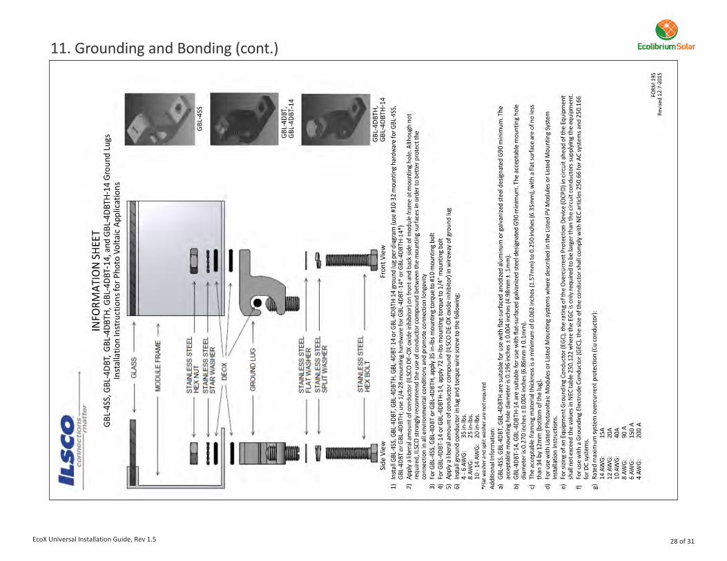
Lugs and System Bonding Install a single ground lug on each array in a visible location. Each ground lug is to be grounded to the common ground identified for this system in accordance with the National Electric Code, ANSI/NFPA 70.l Wiley WEEB-LUG-6.7l Ilsco Lay-in Lug GBL-4DBTl Burndy CL50-1TN
Other UL 2703 listed ground lugs may also be suitable for this system if approved by the Authority Having Jurisdiction (AHJ).Site specific plans are to identify grounding conductor size, type and temperature rating (if appropriate) as determined by a qualified engineer and approved by the AHJ.The installer is responsible for ensuring the ground connection is properly installed per NEC requirements, including the gage of the EGC wire to be used.The installer is also responsible for obtaining prior approval from the AHJ for the use of any grounding lug not listed above.
Ensure that bare copper wire is isolated from all aluminum components.
Module(any location approved by the module manufacturer)
Ground Lug
One ground lug per array must be installed. Ground lug can be installed on the module frame at the end of the array or on the EcoX Skirt or Base components as indicated in the drawing above and approved by the AHJ.
Base(any flat, accessible surface with clearance for a torque wrench)
Skirt(any flat, accessible surface with clearance for a torque wrench)
l Install approved grounding lug perlug manufacturer’s instructions.Instructions included in thefollowing pages.
l Deburr any field-drilled holes.l Wiley WEEB Lugs are “single use only“.
25 of 31
11. Grounding and Bonding (cont.)
EcoX Universal Installation Guide, Rev 1.5
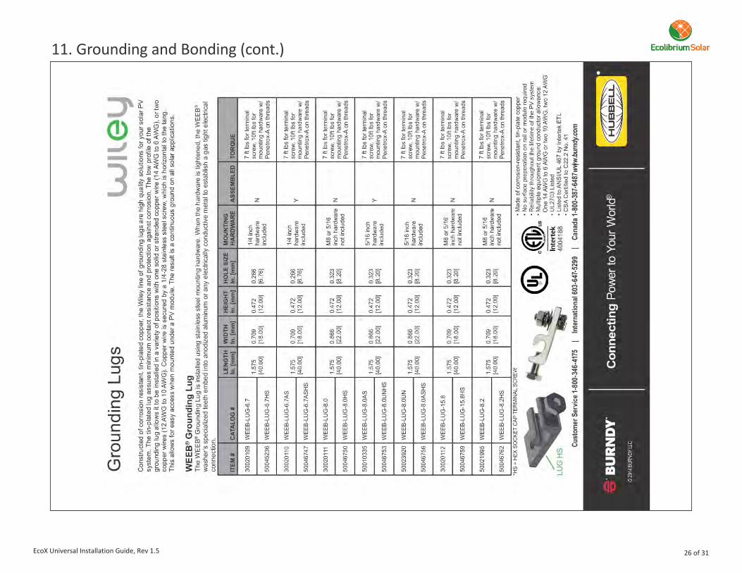
EcoX Universal Installation Guide, Rev 1.5 26 of 31
11. Grounding and Bonding (cont.)

EcoX Universal Installation Guide, Rev 1.5 27 of 31
11. Grounding and Bonding (cont.)
EcoX Universal Installation Guide, Rev 1.5 28 of 31
11. Grounding and Bonding (cont.)

System Bonding Overview Skirt row continuous bond:
Continuous bond from Base and Clamp to Skirt. Couplings bond Skirt to Skirt. Complete row of Skirts and EcoX components clamped to Skirt are bonded.Module row continuous bond:
Continuous bond from Flashing through Clamp to Module. Couplings bond Module-to-Module. Complete row of Modules and EcoX components clamped to Modules are bonded.Row to row bonding:
Bond Clip added to uphill side of one Clamp per row. This bonds Skirt row to Modules on downhill row, and Module row to next Module row on each subsequent row.
1
2
3
1
2
2
3
3
3
Coupling
Coupling
Skirt
Base
Flashing
Clamp
29 of 31
11. Grounding and Bonding (cont.)
EcoX Universal Installation Guide, Rev 1.4
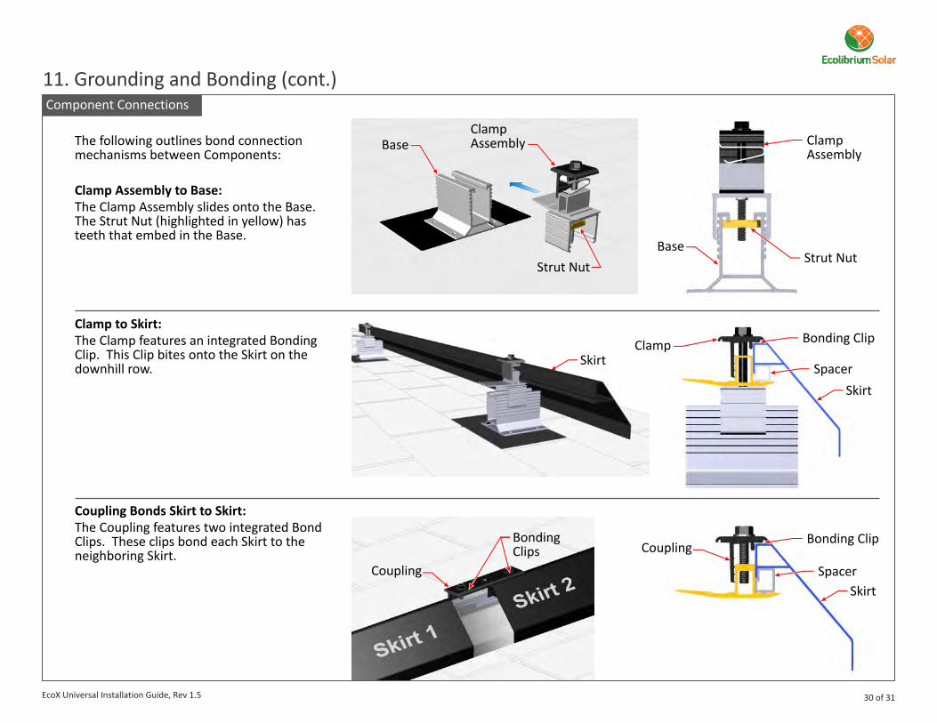
Component Connections
The following outlines bond connection mechanisms between Components:
Clamp Assembly to Base:The Clamp Assembly slides onto the Base. The Strut Nut (highlighted in yellow) has teeth that embed in the Base.
Clamp to Skirt:The Clamp features an integrated Bonding Clip. This Clip bites onto the Skirt on the downhill row.
Coupling Bonds Skirt to Skirt:The Coupling features two integrated Bond Clips. These clips bond each Skirt to the neighboring Skirt.
Base
BaseStrut Nut
Strut Nut
ClampAssembly Clamp
Assembly
Clamp
Coupling
Coupling
Bonding Clip
Spacer
Bonding Clips
Skirt
Skirt
Bonding Clip
SpacerSkirt
30 of 31
11. Grounding and Bonding (cont.)
EcoX Universal Installation Guide, Rev 1.5

ModuleModule
orSkirt
Module
Component Connections (cont.)
Clamp to Module:The Clamp features an integrated Bonding Clip. The Clamp bonds to the Module downhill from the Clamp.
Coupling Bonds Module to Module:The Coupling features two integrated Bonding Clips. On module rows, the Coupling bonds each Module to the neighboring Module. The Coupling is not approved for bonding row-to-row.
Bond Row to Row:Additional bonding must be added to bond the Skirt row to the first row of Modules, and to bond each row of Modules together. There are two options to accomplish this, they are as follows:
Option 1: Add a Bond Clip to the uphill side of each Clamp.
Option 2: Use an approved bonding jumper. A jumper is required between the Skirt and the first row of Modules, and between every row of Modules. Either side of the array is acceptable.
Coupling
Integrated Bonding Clips
Module 1
Module 2
Module
IntegratedBonding Clip
ClampAssembly
Bonding Jumper bonds Module-to-Module and/or Skirt to Module
Install Bonding Clip onto Upper Clamp.
31 of 31
11. Grounding and Bonding (cont.)
EcoX Universal Installation Guide, Rev 1.5
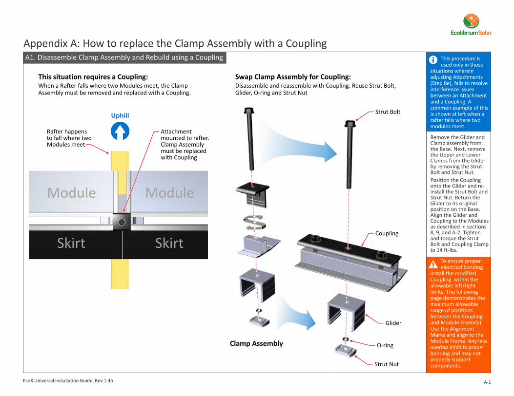
Appendix A: How to replace the Clamp Assembly with a CouplingThis procedure is used only in those
situations wherein adjusting Attachments (Step 8e), fails to resolve interference issues between an Attachment and a Coupling. A common example of this is shown at left when a rafter falls where two modules meet.
To ensure proper electrical bonding
install the modified Coupling within the allowable left/right limits. The following page demonstrates the maximum allowable range of positions between the Coupling and Module Frame(s). Use the Alignment Marks and align to the Module Frame. Any less overlap inhibits proper bonding and may not properly support components.
Remove the Glider and Clamp assembly from the Base. Next, remove the Upper and Lower Clamps from the Glider by removing the Strut Bolt and Strut Nut.Position the Coupling onto the Glider and re-install the Strut Bolt and Strut Nut. Return the Glider to its original position on the Base. Align the Glider and Coupling to the Modules as described in sections 8, 9, and A-2. Tighten and torque the Strut Bolt and Coupling Clamp to 14 ft-lbs.
Rafter happens to fall where two Modules meet
Attachmentmounted to rafter. Clamp Assembly must be replaced with Coupling
Module Module
Skirt Skirt
Strut Bolt
Coupling
Clamp Assembly
Glider
O-ring
Strut Nut
This situation requires a Coupling:When a Rafter falls where two Modules meet, the Clamp Assembly must be removed and replaced with a Coupling.
Swap Clamp Assembly for Coupling:Disassemble and reassemble with Coupling. Reuse Strut Bolt, Glider, O-ring and Strut Nut
A-1
A1. Disassemble Clamp Assembly and Rebuild using a Coupling
EcoX Universal Installation Guide, Rev 1.45

Range
A2. Utilizing the Alignment Marks for Proper alignment of Coupling to Modules and Skirts Just as in earlier steps, the Coupling must be properly aligned in order for bonding to occur and also to properly support the Modules and/or skirts.
When replacing a Clamp Assembly with a Coupling verify that the left/right positioning of the Coupling will fall within the acceptable range of positioning as shown to the left. Remember, after the Coupling is installed it is in a fixed left/right position and cannot be adjusted because it is secured to the Glider and Base attachment to the rooftop.
For Modules that are constructed
with non-metallic corners, ensure the Bonding Clip in the Coupling is fully engaged with the metallic frame of the Module as shown in step 9-e.
If the Coupling is not within the
acceptable range of positioning the Bonding Clips (within its Upper Clamp) will fail to make proper contact with the Modules and/or Skirts. Correct positioning to the Alignment Marks ensures the Bonding Clips are making contact with the Modules and/or Skirts concluding in a proper bond.
Module Module
Skirt Skirt
IncorrectCoupling position exceeds the allowable range. Alignment Mark is
not in-line with Module Frame. Inadequate Module and Skirt support. Bonding will be inhibited.
Alignment Marknot aligned withModule Frame
Alignment Markaligned withModule Frame
Alignment Markaligned withModule Frame
Module Frame
Module Frame Module Frame
Alignment Marks
Range
Range Range
Acceptable Range of PositioningCoupling has a maximum allowable range of positioning
and must not exceed this range.Using Alignment Marks keeps the range in check.
Outermost Positioning - Scenario OneAlignment Marks properly aligned with Module Frame
Outermost Positioning - Scenario TwoAlignment Marks properly aligned with Module Frame
A-2
Appendix A: How to replace the Clamp Assembly with a Coupling (cont.)
EcoX Universal Installation Guide, Rev 1.5
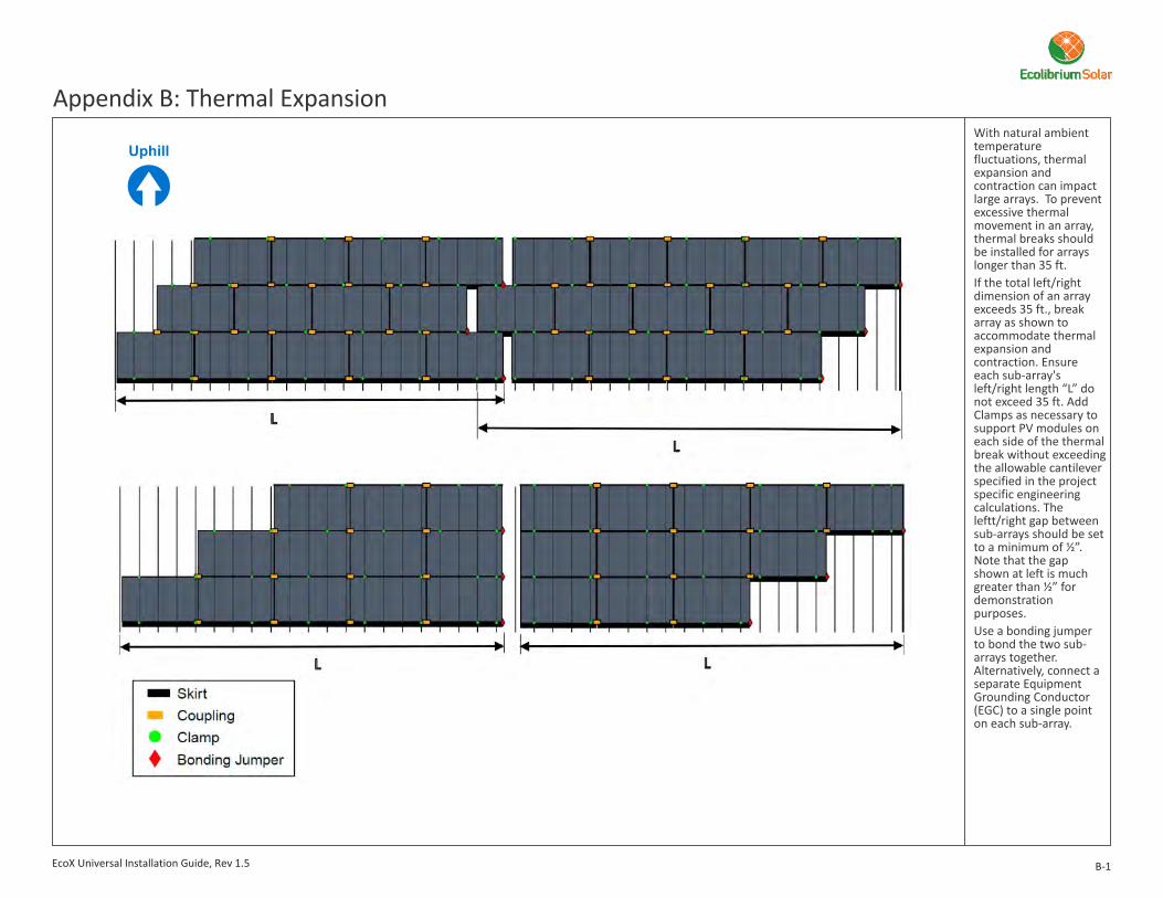
B-1
Appendix B: Thermal ExpansionWith natural ambient temperature fluctuations, thermal expansion and contraction can impact large arrays. To prevent excessive thermal movement in an array, thermal breaks should be installed for arrays longer than 35 ft. If the total left/right dimension of an array exceeds 35 ft., break array as shown to accommodate thermal expansion and contraction. Ensure each sub-array's left/right length “L” do not exceed 35 ft. Add Clamps as necessary to support PV modules on each side of the thermal break without exceeding the allowable cantilever specified in the project specific engineering calculations. The leftt/right gap between sub-arrays should be set to a minimum of ½”. Note that the gap shown at left is much greater than ½” for demonstration purposes.Use a bonding jumper to bond the two sub-arrays together. Alternatively, connect a separate Equipment Grounding Conductor (EGC) to a single point on each sub-array.
EcoX Universal Installation Guide, Rev 1.5

Follow these procedures to ensure extended safety and performance.
C-1
Appendix C: Service and MaintenanceEcolibrium recommends periodic re-inspection of the installation for loose components, loose fasteners, and any corrosion, such that if found, the affected components are to be immediately replaced.If module removal is required, it is the installers responsibility to ensure the ground path is maintained when the module is removed. One of two bonding options may be utilized:Option 1 (for use on a single row array):A. Install an approvedground lug on adjacentmodules.l Wiley WEEB-LUG-6.7l Ilsco Lay-in Lug GBL-
4DBTl Burndy CL50-1TN
Other UL 2703 listed, outdoor rated (by others) ground lugs may also be suitable for this system if approved by the AHJ (Authority Having Jurisdiction). Install ground lug on both of the modules adjacent to the module to be removed. Use the grounding hole on the frame of the module. See section 10 for additional ground lug information.B. Connect a BondingJumper.Lay a bare #6 CU conductor (by others) into the two lay in lugs connected to the adjacent modules.Option 2 (for use on a multiple row array):Install a row to row bonding on either end of the row.
#6 CU Conductor
#6 CU Conductor
Underside ofModule
l Install approved grounding lug perlug manufacturers instructions. SeeSection 10.
l Deburr any field-drilled holes.l Wiley WEEB Lugs are “single use
only“.
Ground Lug Ground Lug
EcoX Universal Installation Guide, Rev 1.5

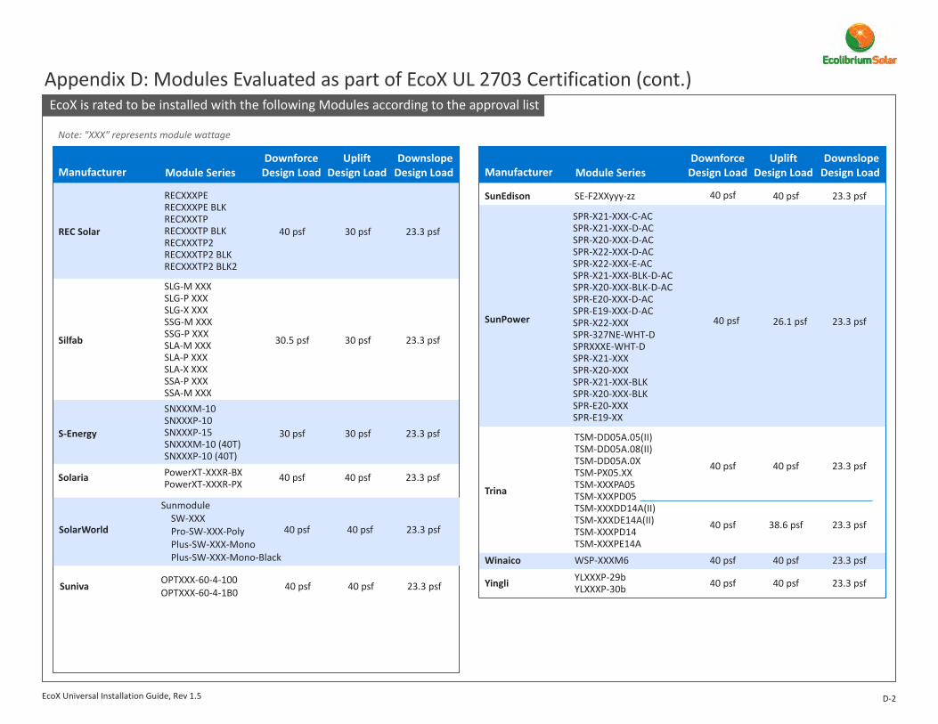
EcoX is rated to be installed with the following Modules according to the approval list
D-1
Appendix D: Modules Evaluated as part of EcoX UL 2703 Certification
(continued)
Jinko (continued)
40 psf
40 psf
40 psf
30 psf
30 psf
40 psf
23.3 psf
23.3 psf
23.3 psfLG Electronics
LGXXXE1C-A5LGXXXN1K-A5LGXXXN1C-A5LGXXXN2W-A5LGXXXQ1C-A5 LGXXXS1C-A5LGXXXS2W-A5LGXXXA1C-G4LGXXXN1C-G4LGXXXN1K-G4LGXXXS1C-G4LGXXXS1K-G4LGXXXN1C-B3LGXXXS1K-B3LGXXXS1C-B3LGXXXA1C-B3
JKMXXXM-60-V JKMXXXPP-60 JKMXXXPP-60(Plus) JKMXXXPP-60-J4 JKMXXXPP-60-V JKMSXXXPP-60 JKMXXXPP-72 JKMXXXM-72(Plus) JKMXXXM-72 JKMXXXPP-72(Plus) JKMXXXPP-72-V
Longi 40 psf
Panasonic
30 psf
40 psf
23.3 psf
30 psf
LR6-60-XXXMLR6-60BK-XXXMLR6-60PB-XXXMLR6-60PE-XXXMLR6-60PH-XXXM
23.3 psf
VBHNXXXSA17
VBHNXXXKA03
30 psf 30 psf 23.3 psf
40 psf 40 psf 23.3 psfCertainTeed
Hyundai
HiS-MXXXMGHiS-MXXXRGHiS-MXXXRWHiS-SXXXRG
40 psf 40 psf 23.3 psf
40 psf
40 psf
40 psf
40 psf
30 psf
40 psf
23.3 psf
23.3 psf
23.3 psf
Centrosolar
Flex
Boviet SolarTechnologies
BVM6610P-XXXBVM6610M-XXXBVM6610M(BB)-XXXBVM6610P(BB)-XXX
Hansol 40 psf 30 psf 23.3 psfHSXXXTD-AN4HSXXXTD-AN3HSXXXUD-AN1
CTXXXMxx-01CTXXXMxx-02
40 psf 40 psf 23.3 psfCanadian Solar
BM60-XXX BB
FLV-MA-XXXP60AB
CS6P-XXXMCS6P-XXXP
Note: "XXX" represents module wattage
Manufacturer Module SeriesDownforce
Design LoadUplift
Design Load DownslopeDesign Load
Hanwha/Q-Cells 40 psf 40 psf 23.3 psf
Q.PEAK-G3Q.PEAK-G4Q.PEAK-G4.1Q.PEAK BLK-G4Q.PEAK BLK-G4.1Q.PLUS-BFR-G4.1Q.PEAK DUO-G5Q.PEAK DUO BLK-G5Q.PLUS-G3Q.PLUS-G4Q.PRO-G3Q.PRO-G4Q.PRO-BFR-G3Q.PRO-BFR-G4
Manufacturer Module SeriesDownforce
Design LoadUplift
Design Load DownslopeDesign Load
EcoX Universal Installation Guide, Rev 1.5
Jinko
JKMXXXM-48 JKMXXXM-60 JKMXXXM-60B
40 psf 30 psf 23.3 psf
VBHNXXXSA17EVBHNXXXSA17G
EcoX is rated to be installed with the following Modules according to the approval list
D-2
Appendix D: Modules Evaluated as part of EcoX UL 2703 Certification (cont.)
40 psf 30 psf 23.3 psfREC Solar
RECXXXPERECXXXPE BLKRECXXXTPRECXXXTP BLKRECXXXTP2RECXXXTP2 BLKRECXXXTP2 BLK2
40 psf 40 psf 23.3 psfWinaico
40 psf 38.6 psf 23.3 psf
Trina
40 psf 40 psf 23.3 psfYingli
WSP-XXXM6
YLXXXP-29bYLXXXP-30b
40 psf 40 psf 23.3 psfSunEdison SE-F2XXyyy-zz
TSM-DD05A.05(II)TSM-DD05A.08(II)TSM-DD05A.0XTSM-PX05.XXTSM-XXXPA05TSM-XXXPD05TSM-XXXDD14A(II) TSM-XXXDE14A(II)TSM-XXXPD14TSM-XXXPE14A
40 psf 40 psf 23.3 psf
Note: "XXX" represents module wattage
30.5 psf 30 psf 23.3 psfSilfab
30 psf 30 psf 23.3 psfS-Energy
SNXXXM-10SNXXXP-10SNXXXP-15SNXXXM-10 (40T)SNXXXP-10 (40T)
SLG-M XXXSLG-P XXXSLG-X XXXSSG-M XXXSSG-P XXXSLA-M XXXSLA-P XXXSLA-X XXXSSA-P XXXSSA-M XXX
40 psf 40 psf 23.3 psfSolaria PowerXT-XXXR-BXPowerXT-XXXR-PX
Manufacturer Module SeriesDownforce
Design LoadUplift
Design Load DownslopeDesign Load Manufacturer Module Series
DownforceDesign Load
UpliftDesign Load
DownslopeDesign Load
EcoX Universal Installation Guide, Rev 1.5
SunPower
SPR-X21-XXX-C-ACSPR-X21-XXX-D-ACSPR-X20-XXX-D-ACSPR-X22-XXX-D-ACSPR-X22-XXX-E-ACSPR-X21-XXX-BLK-D-ACSPR-X20-XXX-BLK-D-ACSPR-E20-XXX-D-ACSPR-E19-XXX-D-ACSPR-X22-XXXSPR-327NE-WHT-DSPRXXXE-WHT-DSPR-X21-XXXSPR-X20-XXXSPR-X21-XXX-BLKSPR-X20-XXX-BLKSPR-E20-XXXSPR-E19-XX
40 psf 40 psf 23.3 psfSolarWorld
Sunmodule SW-XXXPro-SW-XXX-PolyPlus-SW-XXX-MonoPlus-SW-XXX-Mono-Black
OPTXXX-60-4-100OPTXXX-60-4-1B0 40 psf 40 psf 23.3 psfSuniva
40 psf 26.1 psf 23.3 psf
Ecolibrium Solar Power Accessory Bracket
E-1
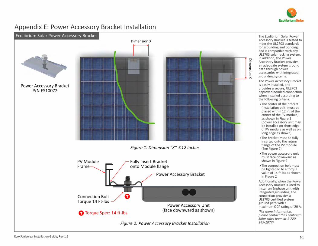
Appendix E: Power Accessory Bracket InstallationThe Ecolibrium Solar Power Accessory Bracket is tested to meet the UL2703 standards for grounding and bonding, and is compatible with any UL2703 solar racking system. In addition, the Power Accessory Bracket provides an adequate system ground path through power accessories with integrated grounding systems. The Power Accessory Bracket is easily installed, and provides a secure, UL2703 approved bonded connection when installed according to the following criteria:
The center of the bracket (installation bolt) must be placed within 12 in. of the corner of the PV module, as shown in Figure 1 (power accessory unit may be installed on short edge of PV module as well as on long edge as shown)The bracket must be fully inserted onto the return flange of the PV module (See Figure 2)The power accessory unit must face downward as shown in Figure 2The connection bolt must be tightened to a torque value of 14 ft-lbs as shown in Figure 2
Additionally, when the Power Accessory Bracket is used to install an Enphase unit with integrated grounding, the connection provides a UL2703 certified system ground path with a maximum OCP rating of 20 A.(For more information, please contact the Ecolibrium Solar sales team at 1-720-249-1877)
l
l
l
l
Power Accessory BracketP/N ES10072
Figure 1: Dimension “X“ ≤12 inches
Figure 2: Power Accessory Bracket Installation
Fully insert Bracketonto Module flange
Connection BoltTorque 14 Ft-lbs
Power Accessory Unit(face downward as shown)
Power Accessory Bracket
PV Module Frame
Dimension X
Dimension X
Torque Spec: 14 ft-lbs
EcoX Universal Installation Guide, Rev 1.5

Height settings are made by utilizing the 5-position dovetailedengagements of theGlider-to-Base. Theimage to the left showsthree of these positions.1" range of travel is possible in 1/4" increments. This equates to 1/8" variation from Glider to adjacent Glider to adjustment and compensate for irregular or undulating roof tops.Start by setting the Glider on the end-of-row Clamps to their middle position and then adjust other Clamps along the row as needed to level the row.
Appendix F: Installing the Skirt-Less Clamp Assemblies1a. How to Clamp Assembly Height via the GliderSet the
Highest Position Middle Position(start here)
Lowest Position
DovetailedEngagementschange elevationin 1/4" increments
Glider
Align Highest setting Mark
of Glider to top of Base
Align Middle setting Mark of Glider to top of Base
Align Lowest setting Mark of Glider to top of Base
1" range of adjustment (1/4" increments)between High & Low positions
ClampAssembly
(includes Glider)
Base
1b. Install the Clamp Assemblies
Glider
Acceptable rangefor uphill edgeof Glider.
Base
Base
ClampAssembly
Two vacant slots at Top
Two vacant slots at Bottom
Start in Middle Position
F-1
LowestSetting Marks:
MiddleHighest
Glider
Uphill edgeof Glider
Base
AlignmentMarks
Align DovetailEngagements andSlide onto Base
Set Glider atApprox. 1 inch
Glider
This Glider is aligned outside of the acceptable
range and must be repositioned.
EcoX Universal Installation Guide, Rev 1.5

Use an impact driver to tighten the Strut Bolt and engage the Strut Nut channels with the two flanges of the Base. Leave the Clamp open to accept the Module.Further tightening will be done as the Modules are installed.
1c. Engage Strut Nut with Base
Strut Bolt
Strut Nut
Flanges
Channels
A String Line is used to level and align Clamp Assemblies on the first downhill row only.The body of the Glider includes one “String Groove” specifically designed to assist with this process.Run and secure the String Line between the two outermost left/right Clamp Assemblies. Place String on the top String Grooves, pulling it taught and securing its ends.
Torque to: 14 ft-lbs
2a. Run a E-W String Line
String Groove
Run String on uphill side of Clamp AssemblyPosition String
on top groove of the twooutermost left/right Clamp Assemblies
F-2
App. F: Install the Skirt-Less Clamp Assemblies (cont.) App. F: Level and Align the Skirt-Less Clamp Assemblies
EcoX Universal Installation Guide, Rev 1.5

Solution:Raise Glider one Dovetail Engagement (1/4") to align Top Groove of Glider with String
2b. Level and Align to String Line
Left Clamp Assembly
Right Clamp Assembly
String Line
String Line
Problem:Top Groove not aligned with String Line
Base
StringGroove(Top Groove)
Height Adjustments
F-3
Uphill/Downhill Adjustments
String Line
Gap
Problem:Gap too largebetween String Line and Glider
Solution:
sliding GliderToward Stringleaving a gap of 1/16" or less
Reduce gap by
String Line
GliderGlider
Base Base
Appendix F: Level and Align Clamp Assemblies (cont.)
EcoX Universal Installation Guide, Rev 1.5

3a. Pivot Modules into Clamps & Couplings Hold the module on its uphill edge,
and place its downhill edge onto Gliders.
Pivot uphill edge downward toward
the uphill Base.Rest the Module on the Base.Be certain that the Module Frame has
fully seated into/against the Clamps.
Place Module on Gliders
Rest Module on uphill Base
Pivot Module downward while pushing it into the Clamp Assembly
1
1
2
2
3
3
Uphill BaseClamp Assembly
module starting position
module resting position
View looking from left edge
4Ensure that Module is fully seated in Clamp Assembly and Coupling
4
module
F-4
Appendix F: Install Modules
EcoX Universal Installation Guide, Rev 1.5
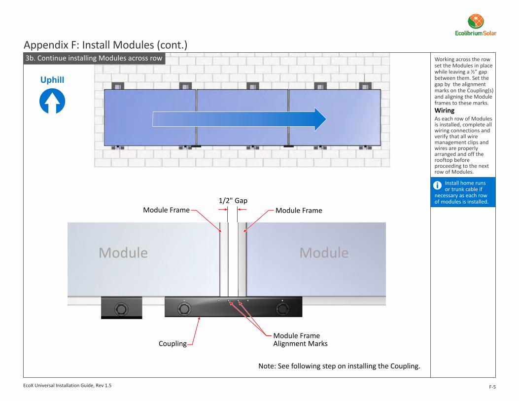
3b. Continue installing Modules across row
Module Frame
Module FrameAlignment MarksCoupling
Note: See following step on installing the Coupling.
Module Frame
Module Module
1/2" Gap
Working across the row set the Modules in place while leaving a ½” gap between them. Set the gap by the alignment marks on the Coupling(s) and aligning the Module frames to these marks.
As each row of Modules is installed, complete all wiring connections and verify that all wire management clips and wires are properly arranged and off the rooftop before proceeding to the next row of Modules.
Wiring
Install home runs or trunk cable if
necessary as each row of modules is installed.
F-5
Appendix F: Install Modules (cont.)
EcoX Universal Installation Guide, Rev 1.5
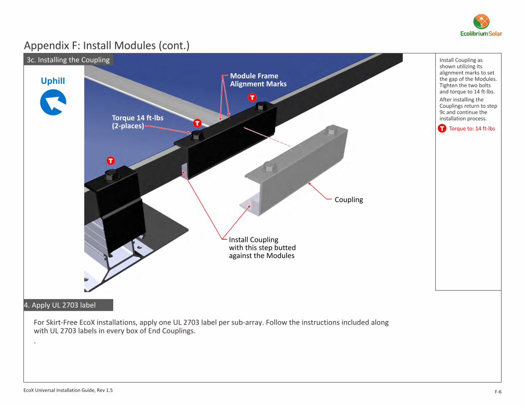
Module FrameAlignment Marks
Coupling
Install Coupling with this step buttedagainst the Modules
Install Coupling as shown utilizing its alignment marks to set the gap of the Modules. Tighten the two bolts and torque to 14 ft-lbs.After installing the Couplings return to step 9c and continue the installation process.
Torque to: 14 ft-lbs
F-6
Appendix F: Install Modules (cont.)
Torque 14 ft-lbs(2-places)
EcoX Universal Installation Guide, Rev 1.5
4. Apply UL 2703 label
3c. Installing the Coupling
For Skirt-Free EcoX installations, apply one UL 2703 label per sub-array. Follow the instructions included along with UL 2703 labels in every box of End Couplings..
Installing EcoX using Commercial Membrane Roof Attachments
G-1
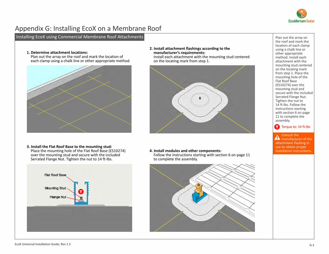
Appendix G: Installing EcoX on a Membrane RoofPlan out the array on the roof and mark the location of each clamp using a chalk line or other appropriate method. Install each attachment with the mounting stud centered on the locating mark from step 1. Place the mounting hole of the Flat Roof Base (ES10274) over the mounting stud and secure with the included Serrated Flange Nut. Tighten the nut to 14 ft-lbs. Follow the instructions starting with section 6 on page 11 to complete the assembly.
Torque to: 14 ft-lbs
Consult themanufacturer of the
attachment flashing in use to obtain proper installation instructions.
1. Determine attachment locations:Plan out the array on the roof and mark the location ofeach clamp using a chalk line or other appropriate method.
3. Install the Flat Roof Base to the mounting stud:Place the mounting hole of the Flat Roof Base (ES10274)over the mounting stud and secure with the includedSerrated Flange Nut. Tighten the nut to 14 ft-lbs.
2. Install attachment flashings according to themanufacturer’s requirements:Install each attachment with the mounting stud centeredon the locating mark from step 1.
4. Install modules and other components:Follow the instructions starting with section 6 on page 11to complete the assembly.
EcoX Universal Installation Guide, Rev 1.5