univ. of tehranintroduction to computer network1 introduction to computer networks university of...
TRANSCRIPT
Univ. of Tehran Introduction to Computer Network
1
Introduction to
Computer Networks
University of TehranDept. of EE and Computer Engineering
By:Dr. Nasser Yazdani
Lecture 6: Packet Switching

Univ. of Tehran Introduction to Computer Network
2
outline Store-and-Forward Switches Bridges and Extended LANs Cell Switching Segmentation and Reassembly

Univ. of Tehran Introduction to Computer Network
3
Scalable Networks Limitation of directly connected
networks. Limit on the number of hosts; For
example, Ethernet is 1024 hosts. Limit on the geographical area of LANs.
2500 m in Ethernet. Solution: This is like telephone
network. Then, use Switches.

Univ. of Tehran Introduction to Computer Network
4
Switches forwards packets from input port to output port
port selected based on address in packet header If two packets are destined to the same output, one
must be buffered (queued). This is called contention. Needs some kinds of scheduling for packet delivery.
If the buffer overflow, it will be a congestion.
Inputports
T3T3
STS-1
T3T3STS-1
Switch
Outputports

Univ. of Tehran Introduction to Computer Network
5
Packet Switching Schemes Source routing: List entire path in the
packet Virtual circuits: like telephone circuit,
identify packets with ids. Datagram: Put only destination address
in packets’ headers.

Univ. of Tehran Introduction to Computer Network
6
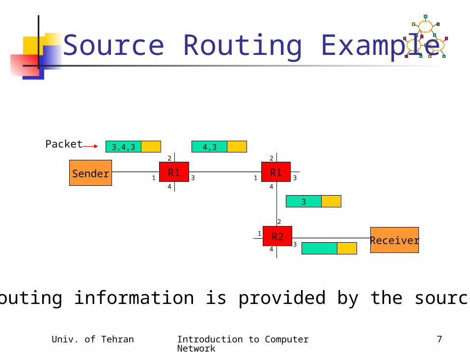
Source Routing List entire path in packet
Driving directions (north 3 hops, east, etc..)
Router processing, one option Examine first step in directions Strip first step from packet Forward to step just stripped off
Or the address can be implemented by a linked list in the packet header.
Univ. of Tehran Introduction to Computer Network
7
Source Routing Example
Receiver
Packet 3,4,3
Sender
2
34
1
2
34
1
2
34
1
R1
R2
R1
4,3
3
All routing information is provided by the source.
Univ. of Tehran Introduction to Computer Network
8
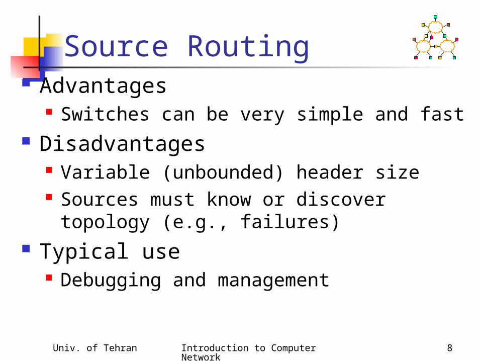
Source Routing Advantages
Switches can be very simple and fast Disadvantages
Variable (unbounded) header size Sources must know or discover topology
(e.g., failures) Typical use
Debugging and management
Univ. of Tehran Introduction to Computer Network
9
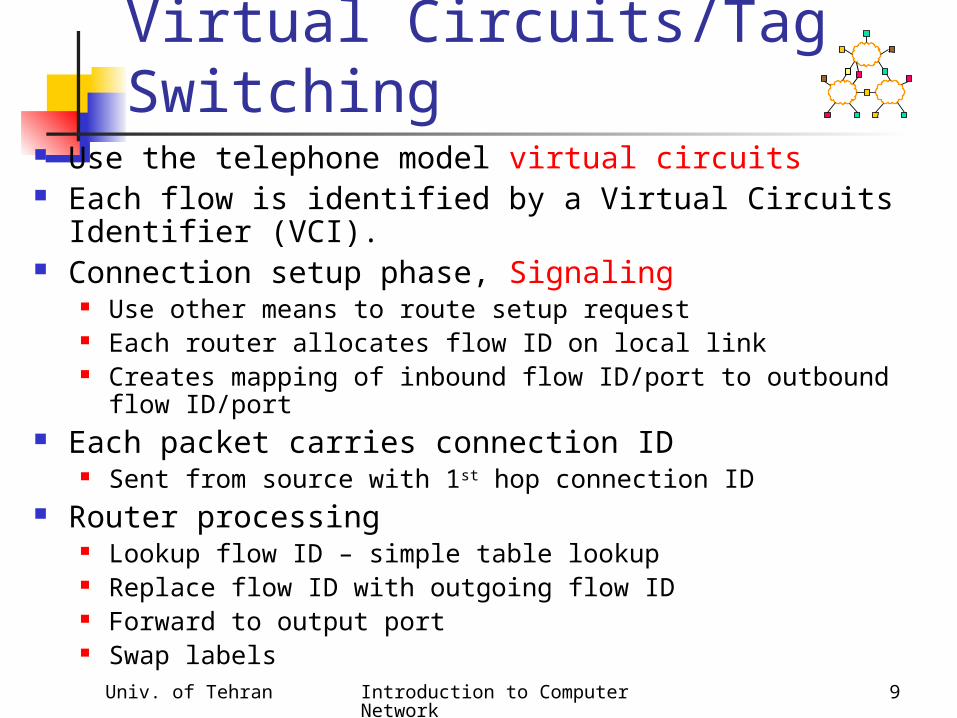
Virtual Circuits/Tag Switching
Use the telephone model virtual circuits Each flow is identified by a Virtual Circuits Identifier
(VCI). Connection setup phase, Signaling
Use other means to route setup request Each router allocates flow ID on local link Creates mapping of inbound flow ID/port to outbound flow
ID/port Each packet carries connection ID
Sent from source with 1st hop connection ID Router processing
Lookup flow ID – simple table lookup Replace flow ID with outgoing flow ID Forward to output port Swap labels
Univ. of Tehran Introduction to Computer Network
10
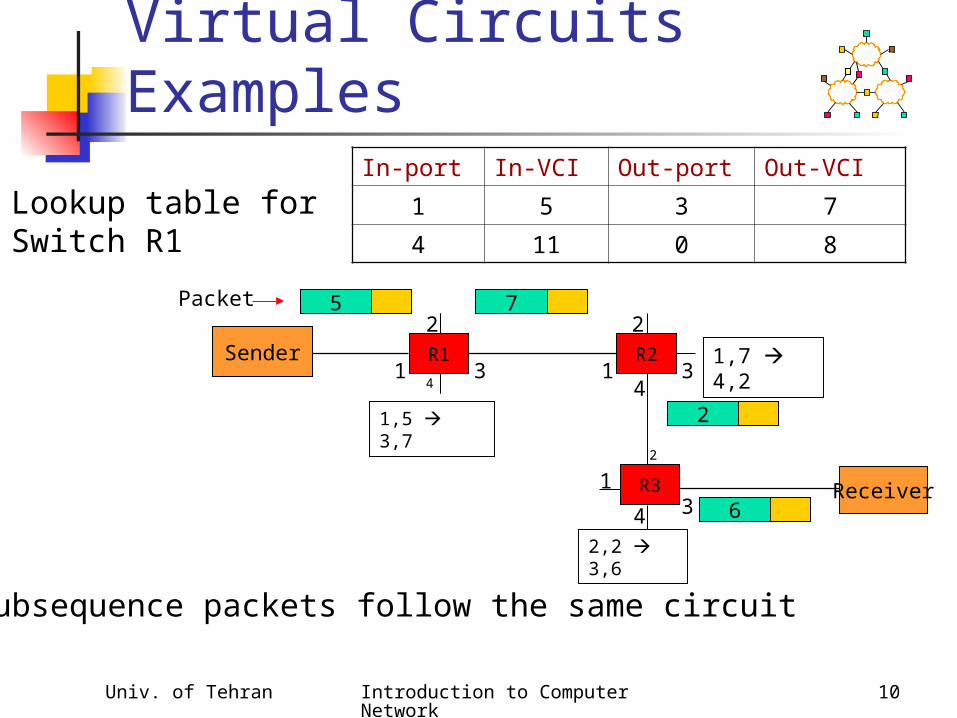
Virtual Circuits Examples
Receiver
Packet
1,5 3,7
Sender2
34
11,7 4,2
2
34
1
2
34
1
2,2 3,6
R2
R3
R1
5 7
2
6
In-port In-VCI Out-port Out-VCI
1 5 3 7
4 11 0 8
Lookup table forSwitch R1
Subsequence packets follow the same circuit

Univ. of Tehran Introduction to Computer Network
11
Virtual Circuits Advantages
More efficient lookup (simple table lookup) More flexible (different path for each flow) Can reserve bandwidth at connection setup Easier for hardware implementations Small per-packet header overhead.
Disadvantages Still need to route connection setup request More complex failure recovery – must recreate
connection state Typical uses
ATM – combined with fix sized cells MPLS – tag switching for IP networks
Univ. of Tehran Introduction to Computer Network
12
Virtual Circuit Model Typically wait full RTT for connection setup before
sending first data packet.
While the connection request contains the full address for destination, each data packet contains only a small identifier, making the per-packet header overhead small.
If a switch or a link in a connection fails, the connection is broken and a new one needs to be established.
Connection setup provides an opportunity to reserve resources.

Univ. of Tehran Introduction to Computer Network
13
Datagram Switching No connection setup phase since it is
costly. Each packet is forwarded independently Sometimes called connectionless model
Analogy: postal system
Each switch maintains a forwarding (routing) table
Receiver
Packet R
Sender
2
34
1
2
34
1
2
34
1
R1
R2
R1
R
RR 3
R 4
R 3
R
Univ. of Tehran Introduction to Computer Network
14
Datagram Model There is no round trip time delay waiting for
connection setup; a host can send data as soon as it is ready.
Source host has no way of knowing if the network is capable of delivering a packet or if the destination host is even up.
Since packets are treated independently, it is possible to route around link and node failures.
Since every packet must carry the full address of the destination, the overhead per packet is higher.

Univ. of Tehran Introduction to Computer Network
15
Bridges and Extended LANs
LANs have physical limitations (e.g., 2500m) Connect two or more LANs with a switch
accept and forward strategy level 2 connection (does not add packet header)
Ethernet Switch is called Bridge traditionally.
A
Bridge
B C
X Y Z
Port 1
Port 2
Univ. of Tehran Introduction to Computer Network
16
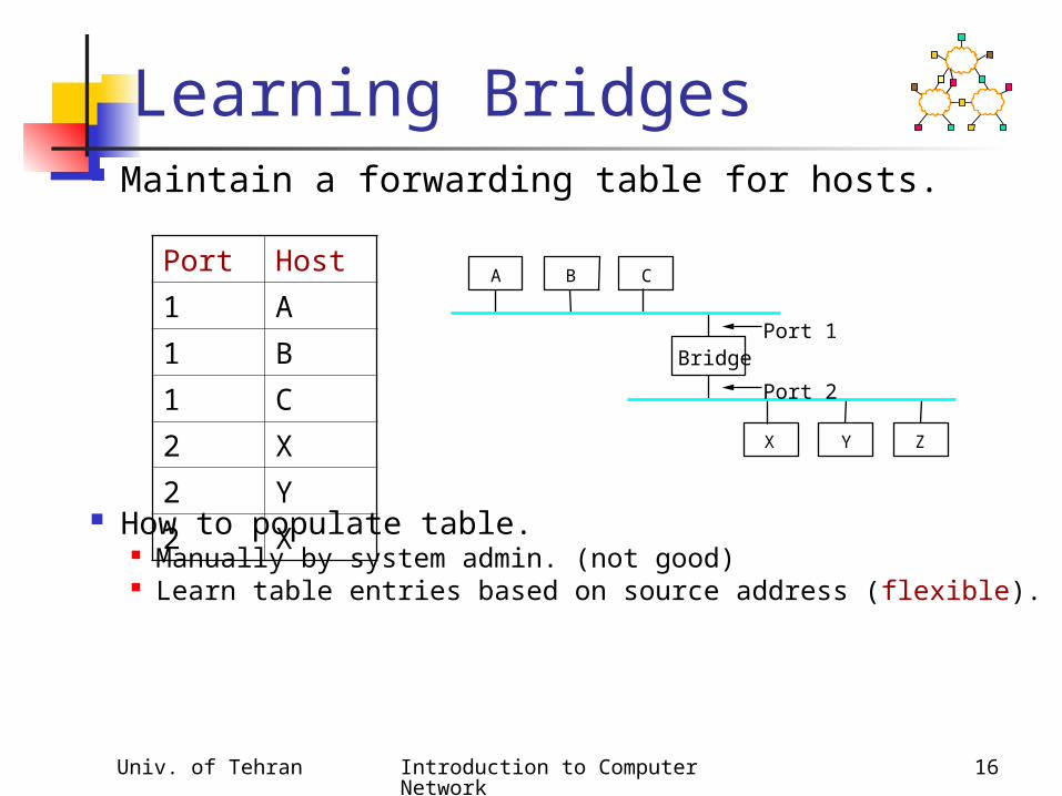
Learning Bridges Maintain a forwarding table for hosts.
How to populate table. Manually by system admin. (not good) Learn table entries based on source address (flexible).
Port Host
1 A
1 B
1 C
2 X
2 Y
2 X
A
Bridge
B C
X Y Z
Port 1
Port 2

Univ. of Tehran Introduction to Computer Network
17
Learning Bridges, (Forwarding)
1. If the frame destination address is in the routing table, forward the frame to the corresponding port.
2. Otherwise, broadcast the frame.3. Update the table if the source address is not in
the table.
Table is an optimization; need not be complete
Always forward broadcast frames

Univ. of Tehran Introduction to Computer Network
18
Spanning Tree Algorithm Problem: loops
Bridges run a distributed spanning tree algorithm select which bridges actively forward developed by Radia Perlman now IEEE 802.1 specification
B3
A
C
E
DB2
B5
B
B7 KF
H
B4
J
B1
B6
G
I
Univ. of Tehran Introduction to Computer Network
19
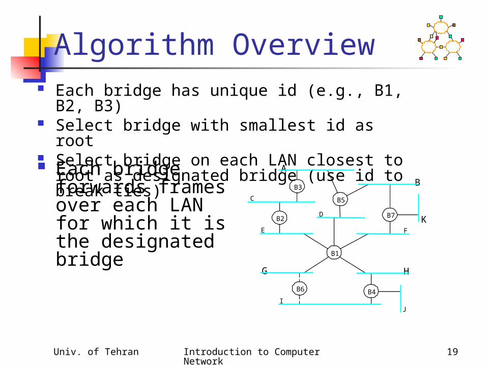
Algorithm Overview Each bridge has unique id (e.g., B1, B2,
B3) Select bridge with smallest id as root Select bridge on each LAN closest to root
as designated bridge (use id to break ties)B3
A
C
E
DB2
B5
B
B7 KF
H
B4
J
B1
B6
G
I
Each bridge forwards frames over each LAN for which it is the designated bridge
Univ. of Tehran Introduction to Computer Network
20
Algorithm Details
Bridges exchange configuration messages id for bridge sending the message id for what the sending bridge believes to be
root bridge distance (hops) from sending bridge to root
bridge Each bridge records current best
configuration message for each port Initially, each bridge believes it is the root

Univ. of Tehran Introduction to Computer Network
21
Algorithm Detail (cont) When learn not root, stop generating config
messages in steady state, only root generates configuration
messages When learn not designated bridge, stop forwarding
config messages in steady state, only designated bridges forward config
messages Root continues to periodically send config messages If any bridge does not receive config message after
a period of time, it starts generating config messages claiming to be the root
Univ. of Tehran Introduction to Computer Network
22
Broadcast and Multicast
Forward all broadcast/multicast frames current practice
Learn when no group members downstream
Accomplished by having each member of group G send a frame to bridge multicast address with G in source field

Univ. of Tehran Introduction to Computer Network
23
Limitations of Bridges Do not scale
spanning tree algorithm does not scale broadcast does not scale
Do not accommodate heterogeneity
Caution: beware of transparency

Univ. of Tehran Introduction to Computer Network
24
Cell Switching (ATM)
Connection-oriented packet-switched network Used in both WAN and LAN settings Signaling (connection setup) Protocol: Q.2931 Specified by ATM forum Packets are called cells
5-byte header + 48-byte payload Commonly transmitted over SONET
other physical layers possible

Univ. of Tehran Introduction to Computer Network
25
Variable vs Fixed-Length Packets
No Optimal Length if small: high header-to-data overhead if large: low utilization for small
messages Fixed-Length Easier to Switch in
Hardware simpler enables parallelism

Univ. of Tehran Introduction to Computer Network
26
Big vs Small Packets Small Improves Queue behavior
finer-grained pre-emption point for scheduling link maximum packet = 4KB link speed = 100Mbps transmission time = 4096 x 8/100 = 327.68us high priority packet may sit in the queue 327.68us in contrast, 53 x 8/100 = 4.24us for ATM
near cut-through behavior two 4KB packets arrive at same time link idle for 327.68us while both arrive at end of 327.68us, still have 8KB to transmit in contrast, can transmit first cell after 4.24us at end of 327.68us, just over 4KB left in queue

Univ. of Tehran Introduction to Computer Network
27
Big vs Small (cont)
Small Improves Latency (for voice) voice digitally encoded at 64KBps (8-bit
samples at 8KHz) need full cell’s worth of samples before
sending cell example: 1000-byte cells implies 125ms per
cell (too long) smaller latency implies no need for echo
cancellors ATM Compromise: 48 bytes = (32+64)/2
Univ. of Tehran Introduction to Computer Network
28
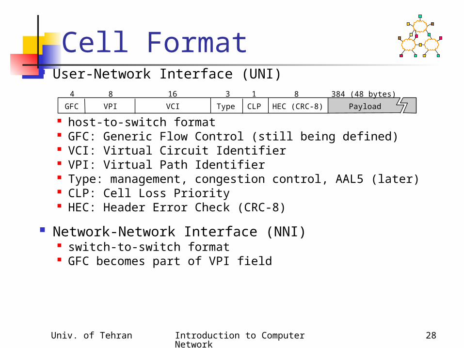
Cell Format User-Network Interface (UNI)
host-to-switch format GFC: Generic Flow Control (still being defined) VCI: Virtual Circuit Identifier VPI: Virtual Path Identifier Type: management, congestion control, AAL5 (later) CLP: Cell Loss Priority HEC: Header Error Check (CRC-8)
Network-Network Interface (NNI) switch-to-switch format GFC becomes part of VPI field
GFC HEC (CRC-8)
4 16 3 18
VPI VCI CLPType Payload
384 (48 bytes)8

Univ. of Tehran Introduction to Computer Network
29
Segmentation and Reassembly
ATM Adaptation Layer (AAL) AAL 1 and 2 designed for applications that need
guaranteed rate (e.g., voice, video) AAL 3/4 designed for packet data AAL 5 is an alternative standard for packet data
AAL
ATM
AAL
ATM
… …

Univ. of Tehran Introduction to Computer Network
30
AAL 3/4
Convergence Sublayer Protocol Data Unit (CS-PDU)
CPI: common part indicator (version field) Btag/Etag:beginning and ending tag BAsize: hint on amount of buffer space to
allocate Length: size of whole PDU
CPI Btag BASize Pad 0 Etag Len
8 16 0– 24 8 8 16< 64 KB8
User data

Univ. of Tehran Introduction to Computer Network
31
Cell Format
Type BOM: beginning of message COM: continuation of message EOM end of message
SEQ: sequence of number MID: message id Length: number of bytes of PDU in this cell
It uses 4 extra bytes for SAR, not good!
ATM header Length CRC-10
40 2 4
SEQ MIDType Payload
352 (44 bytes)10 6 10

Univ. of Tehran Introduction to Computer Network
32
AAL5
CS-PDU Format
pad so trailer always falls at end of ATM cell Length: size of PDU (data only) CRC-32 (detects missing or misordered cells)
Cell Format end-of-PDU bit in Type field of ATM header
CRC-32
< 64 KB 0– 47 bytes 16 16
ReservedPad Len
32
Data
Univ. of Tehran Introduction to Computer Network
33
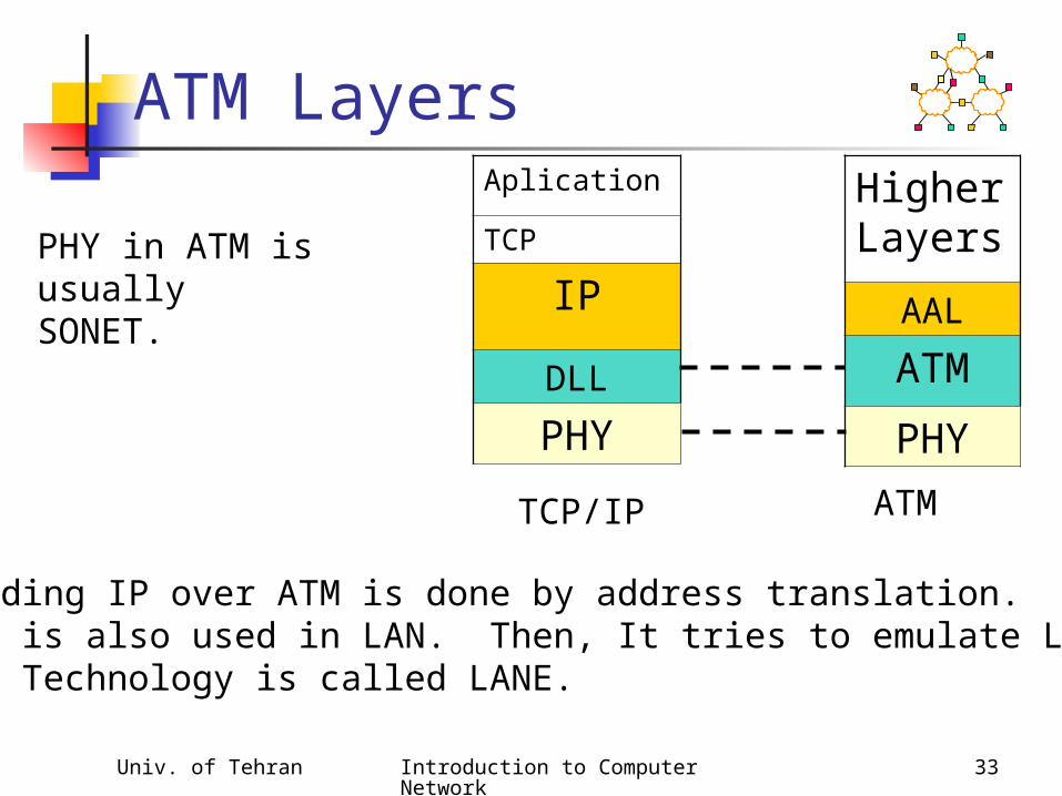
ATM LayersHigher Layers
AAL
ATM
PHY
Aplication
TCP
IP
DLL
PHY
TCP/IP ATM
PHY in ATM is usuallySONET.
• Sending IP over ATM is done by address translation.• ATM is also used in LAN. Then, It tries to emulate LAN.• The Technology is called LANE.