unit 6. visual recognition - downloads.slugsite.comdownloads.slugsite.com/visual-recognition.pdf ·...
TRANSCRIPT
Unit 6. Visual Recognition
6-1. Aircraft Visual Recognition Training ..................................................................................... 6–1 228. Developing and presenting an aircraft recognition program..............................................................6–1
6-2. Naval Vessels ........................................................................................................................... 6–21 229. Naval vessel recognition..................................................................................................................6–21
6-3. Ground Equipment ................................................................................................................. 6–28 230. Ground equipment recognition ........................................................................................................6–28
O be prepared for wartime operations, aircrew members must be able to identify friendly and enemy aircraft at a glance. On 14 April 1994, a US F–15 pilot conducting a mission in support of Operation NORTHERN WATCH over northern Iraq, mistakenly shot down two US UH–60
Blackhawk helicopters which were conducting humanitarian missions. The pilot had mistaken the helicopters for Iraqi Mi–24 Hinds. There were 15 Americans and 11 foreign nationals aboard the US helicopters. There were no survivors. Could this happen to your crews? I would hope not. However, it is up to you to develop a good visual aircraft recognition program to help prevent events such as this. A solid visual recognition program can help avoid tragedies such as the 1994 friendly fire shoot down. One of your most important roles during peacetime is to provide your aircrews with this intelligence-related training.
T
6-1. Aircraft Visual Recognition Training When establishing an aircraft recognition program, you should refer to you MAJCOM instructions requirements. Obviously, your unit mission and aircraft type will drive your aircrew visual recognition-training program. However, no matter what your mission may be, aircraft recognition training will play a central part of your training program. Your pilots’ ability to identify aircraft within a glance is crucial to our role in developing and maintaining air superiority over the battlefield area. Not only must your pilots be familiar with our adversary’s aircraft, they must also recognize the many aircraft who are our allies supporting a coalition effort. Your recognition program will help in preventing friendly fire accidents, further avoiding potential international incidents. Your efforts into your training program help keep our pilots the best in the world.
228. Developing and presenting an aircraft recognition program Developing and presenting an aircraft recognition program for your aircrews is one of your primary duties as an Operations Intelligence technician. Your job is to ensure your aircrews can identify friendly, coalition and adversarial aircraft within a glance. Your aircrews will be tested on their ability to accomplish this task, and must pass a visual recognition test to maintain flying status.
Introduction The threat recognition training program you develop for your squadron should be based on your AOR, MAJCOM directives, and most importantly, your unit mission. Your aircrew recognition training program will cover both visual recognition and threat knowledge of adversarial threats as well as friendly assets. Your aircrew threat recognition training program should stress your aircrews’ ability to identify and understand the characteristics of operational air, naval, ground, missile, and electronic equipment of any nation that could threaten your aircrews’ or its allies. Your aircrews must be able to identify both friendly and enemy equipment, recognize patterns of employment, and know equipment capabilities in order to make effective split second tactical decisions. Also, your aircrews must be able to identify deviations from known equipment characteristics in order to report these deviations through intelligence channels. Sometimes, it also includes military and commercial markings on aircraft. However, your program should place an emphasis particularly on those aircraft that pose a significant threat to your aircrews.
“FOUO” document markings removed by FOIA RSC GAFB07-011

6–2
“FOUO” document markings removed by FOIA RSC GAFB07-011
Background Most unit visual recognition training programs include a little background on each aircraft the aircrews are expected to recognize. This background may include such information as when the aircraft came into service, the aircraft’s primary role, the countries aircraft tactics, and what countries it is deployed to within your AOR. Quite often, recognition and capabilities training are intermixed. If this is the case for your training program, the aircraft armament and tactics might also be included.
Total form concept Total form concept is the method most widely used to teach aircraft recognition; this concept is learning how to recognize the whole aircraft. Some features are obvious upon viewing the aircraft, but seeing those features may depend on the pilot’s angle of view. The recognition procedures you instruct your aircrews’ to use should relate all parts of the aircraft to include its total form. Through your recognition training program, the aircrew members should learn to build a mental picture of the aircraft. From there, your pilots will learn how to recognize aircraft at a glance. Figure 6-1 is a Mig-23 flogger and is offered as an example.
Figure 6–1. Mig–23 Flogger.
You and your aircrew members must learn to recognize an aircraft by building a mental picture of the aircraft. Initially, it will be necessary to go into a detailed analysis of the aircraft’s appearance in order to establish the correct mental picture. Examine each feature not as a recognition feature itself, but as a part of the aircraft’s total form.
Aircraft The primary aircraft your aircrews will identify are fixed, variable geometry and rotary wing aircraft, figure 6-2. The method of instruction for identification of fixed-wing aircraft is the wings, engine, fuselage, and tail, the (WEFT) system. These four characteristics are common to all aircraft, and provide the keys for the proper visual aircraft recognition. You will learn about identifying helicopters using the rotors, engine, fuselage, and tail (REFT) system later in the chapter.

6–3
“FOUO” document markings removed by FOIA RSC GAFB07-011
Figure 6–2. Aircraft wing types.
Wings There are four considerations when you observe aircraft wings: the mounting, shape, tips, and other distinctive features. Figure 6–3 shows an example of three different aircraft wing mount positions.
Figure 6–3. Wing positions.

6–4
“FOUO” document markings removed by FOIA RSC GAFB07-011
Figure 6–4 provides eight basic aircraft wing shapes. Notice that some wing shapes, such as straight-straight and the delta, are identified first by the leading edge of the wing and secondly by the trailing edge of the wing. Most aircraft shares these basic wing shapes, but the basic shape isn’t enough to identify an aircraft properly. Another key in identifying aircraft wings is the shape of the wingtip.
Figure 6–4. Wing shapes.
Various other aircraft wing patterns also make key recognition features. Other considerations to look for in observing aircraft wings are the wing slants and tips. The four common wing slants are listed in Figure 6-5. Sometimes, the wing slants are referred to as positive or negative dihedral. Figure 6–6 lists the five most common wing tip types.
Figure 6–5. Wing Slants.

6–5
“FOUO” document markings removed by FOIA RSC GAFB07-011
Figure 6–6. Wingtips.
Various other airaft wing patterns also make key recognition features. Figure 6-7 provides some of the common terminology used in describing aircraft wings. In figure 6-8, you can see the aircraft wing’s different types of wing tapers.
Wing Feature Description Canards Small stabilizer appendages forward of the wing that provide increased
stability to the aircraft. Canards have no ailerons and may be detachable.
Chine fairings Horizontal fairings attached to the fuselage forward of the wing’s leading edge. Chine fairings improve the structural and aerodynamic characteristics of home aircraft. These fairings may extend the entire length of the fuselage forward of the wing.
Foreplanes Enlarged winglike structures mounted forward of the primary wing. Foreplanes are much larger than canards and have ailerons. Foreplanes are not detachable, but may be retracted into the fuselage.
Stall fences Small vertical fairings running across the upper wing surface, parallel to the fuselage. Stall fences are seen in pairs and are used to improve an aircraft’s stability.

6–6
“FOUO” document markings removed by FOIA RSC GAFB07-011
Flap track fairings Structural fairings extending past the wing trailing edge. These fairings are relatively small and are usually numerous. Flap track fairings allow for the increased extension of the wing flaps to provide additional lift. These fairings are occasionally called canoes.
Wing gear pods Gear housings mounted at the wing trailing edge and extending past the wing. Wing gear pods are not attached to any other structure.
Winglets Near-vertical wingtip appendages that are used to improve the aerodynamic characteristics of some aircraft.
Figure 6-7. Aircraft wing descriptions.
Figure 6–8. Wing Tapers.
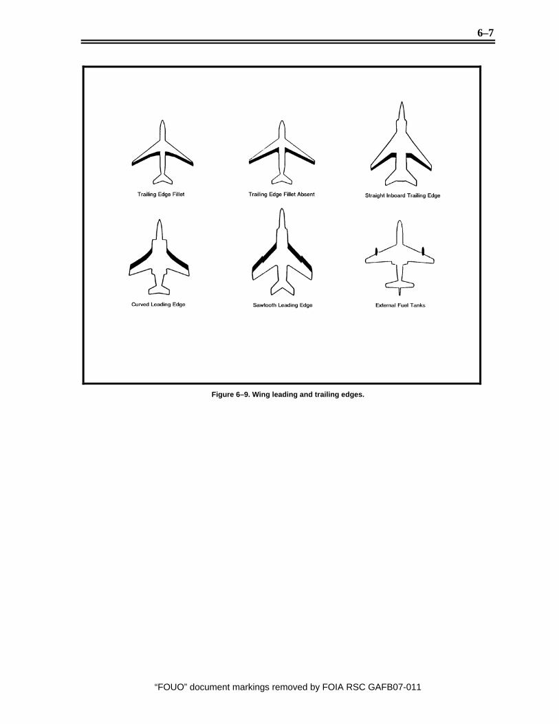
In figure 6-9, the leading and trailing edges of an aircraft’s wing can help in being a key identification feature. Also, non-removable external fuel tanks make a very good key recognition feature. Figure 6-10 identifies other miscellaneous wing features found on some aircraft.
6–7
“FOUO” document markings removed by FOIA RSC GAFB07-011
Figure 6–9. Wing leading and trailing edges.

6–8
“FOUO” document markings removed by FOIA RSC GAFB07-011
Figure 6–10. Miscellaneous wing features.
Engine After you’ve identified the characteristics of the wings, you should focus on the aircraft’s engines. You should be able to identify the type, number, and location of the aircraft’s engines. Aircraft are categorized into either a propeller driven aircraft, or jet engine aircraft as shown in figures 6-11 and 6-12. Specifically, the first easy identification feature is the type and number of engines.
Figure 6–11. Propeller driven aircraft.
6–9
“FOUO” document markings removed by FOIA RSC GAFB07-011
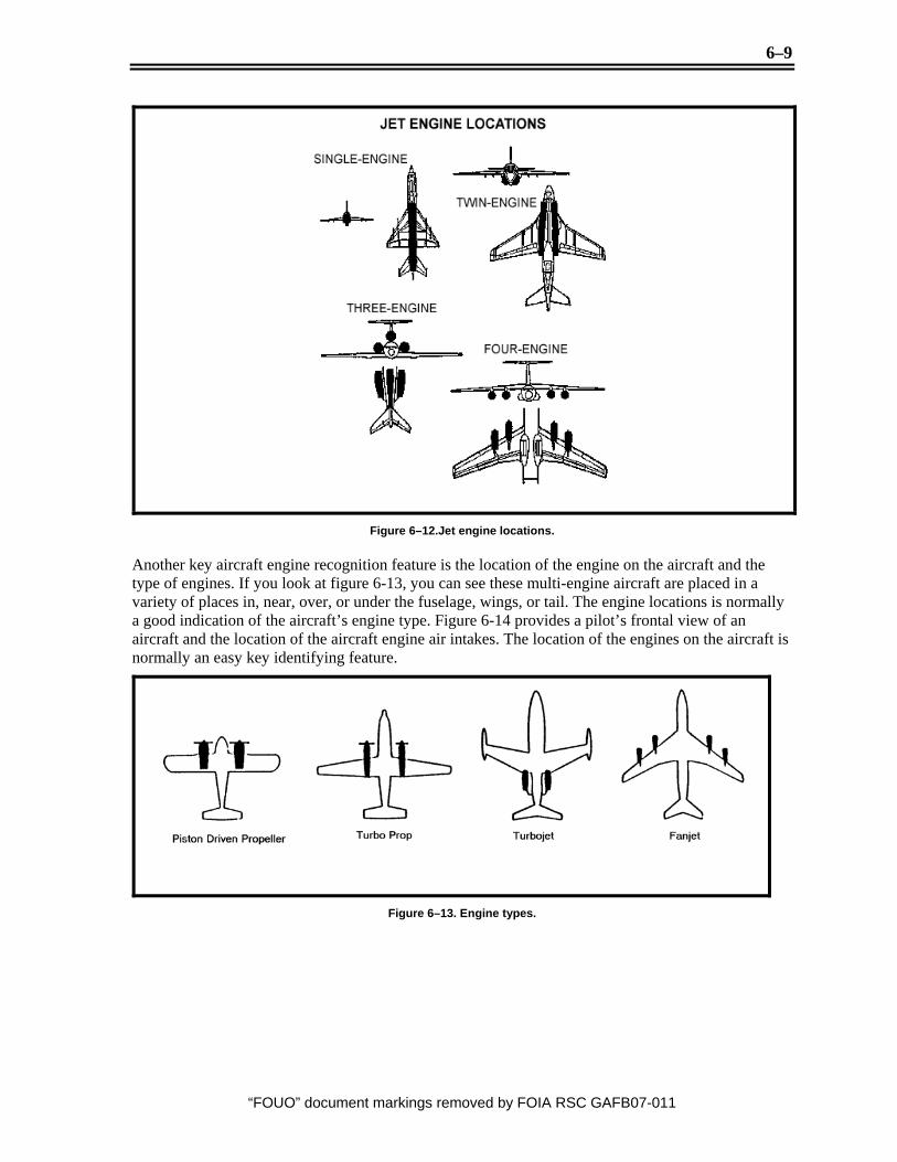
Figure 6–12.Jet engine locations.
Another key aircraft engine recognition feature is the location of the engine on the aircraft and the type of engines. If you look at figure 6-13, you can see these multi-engine aircraft are placed in a variety of places in, near, over, or under the fuselage, wings, or tail. The engine locations is normally a good indication of the aircraft’s engine type. Figure 6-14 provides a pilot’s frontal view of an aircraft and the location of the aircraft engine air intakes. The location of the engines on the aircraft is normally an easy key identifying feature.
Figure 6–13. Engine types.
6–10
“FOUO” document markings removed by FOIA RSC GAFB07-011
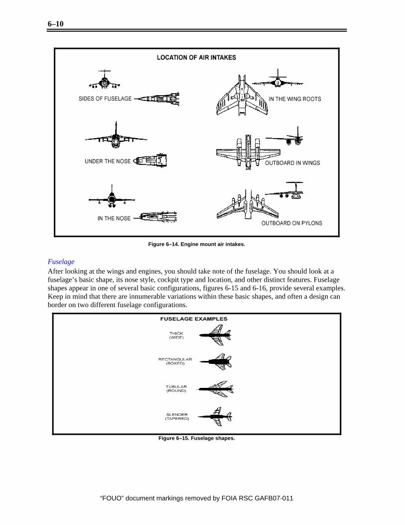
Figure 6–14. Engine mount air intakes.
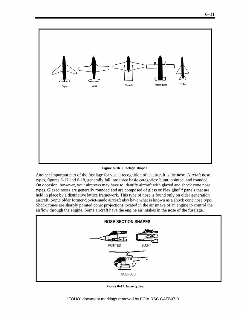
Fuselage After looking at the wings and engines, you should take note of the fuselage. You should look at a fuselage’s basic shape, its nose style, cockpit type and location, and other distinct features. Fuselage shapes appear in one of several basic configurations, figures 6-15 and 6-16, provide several examples. Keep in mind that there are innumerable variations within these basic shapes, and often a design can border on two different fuselage configurations.
Figure 6–15. Fuselage shapes.
6–11
“FOUO” document markings removed by FOIA RSC GAFB07-011
Figure 6–16. Fuselage shapes.
Another important part of the fuselage for visual recognition of an aircraft is the nose. Aircraft nose types, figures 6-17 and 6-18, generally fall into three basic categories: blunt, pointed, and rounded. On occasion, however, your aircrews may have to identify aircraft with glazed and shock cone nose types. Glazed noses are generally rounded and are composed of glass or Plexiglas™ panels that are held in place by a distinctive lattice framework. This type of nose is found only on older generation aircraft. Some older former-Soviet-made aircraft also have what is known as a shock cone nose type. Shock cones are sharply pointed conic projections located in the air intake of an engine to control the airflow through the engine. Some aircraft have the engine air intakes in the nose of the fuselage.
Figure 6–17. Nose types.

6–12
“FOUO” document markings removed by FOIA RSC GAFB07-011
Figure 6–18. Nose types.
Aircraft cockpit types and locations, especially on fighter aircraft, can also provide key identification features. The most common types of cockpits and their locations are shown in figure 6-19. Other cockpit considerations from a side view are show in figure 6-20.

6–13
“FOUO” document markings removed by FOIA RSC GAFB07-011
Figure 6–19. Aircraft cockpits.
Figure 6–20. Aircraft canopy shapes.

6–14
“FOUO” document markings removed by FOIA RSC GAFB07-011
There are other features included on aircraft fuselages that may provide key recognition features, some of which are displayed in figure 6-21. Several fighters have dorsal spines running along the fuselage; the length of these spines can prove to be an identifying characteristic. Some transport aircraft use gear pods attached to the fuselage; these provide a key recognition feature. Most modern fighter aircraft have their engines internally mounted in the fuselage and have air intakes molded into the fuselage. The size, shape, and location of these air intakes often provide the clues to distinguish them from similar-looking fighter aircraft.
Figure 6–21. Miscellaneous fuselage features.
Tail After the fuselage, you should focus your attention on the aircraft’s tail assembly. The tail section can take various forms. You should first concentrate on the basic tail configuration and the aircrafts different types of vertical and horizontal stabilizers, figures 6-22 and 6-23. Some tail assemblies include a vertical stabilizer fairing, which can prove to be a good identification feature. The mounting of the horizontal stabilizer, figure 6-24, can also provide clues as to aircraft identification.

6–15
“FOUO” document markings removed by FOIA RSC GAFB07-011
Figure 6–22 Vertical stabilizers.
Figure 6–23. Vertical stabilizers.
6–16
“FOUO” document markings removed by FOIA RSC GAFB07-011
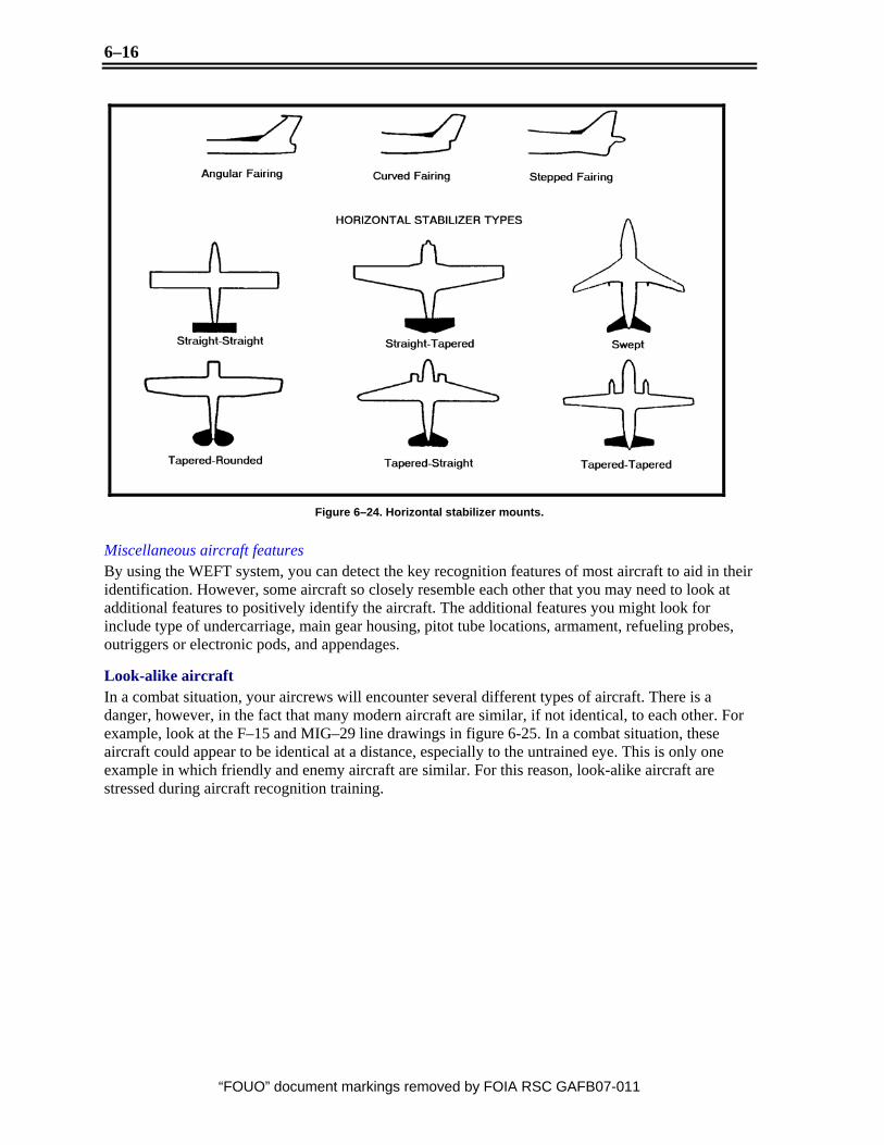
Figure 6–24. Horizontal stabilizer mounts.
Miscellaneous aircraft features By using the WEFT system, you can detect the key recognition features of most aircraft to aid in their identification. However, some aircraft so closely resemble each other that you may need to look at additional features to positively identify the aircraft. The additional features you might look for include type of undercarriage, main gear housing, pitot tube locations, armament, refueling probes, outriggers or electronic pods, and appendages.
Look-alike aircraft In a combat situation, your aircrews will encounter several different types of aircraft. There is a danger, however, in the fact that many modern aircraft are similar, if not identical, to each other. For example, look at the F–15 and MIG–29 line drawings in figure 6-25. In a combat situation, these aircraft could appear to be identical at a distance, especially to the untrained eye. This is only one example in which friendly and enemy aircraft are similar. For this reason, look-alike aircraft are stressed during aircraft recognition training.

6–17
“FOUO” document markings removed by FOIA RSC GAFB07-011
Figure 6–25. Look-alike.
During the training session, you should cover the similarities of the look-alike aircraft and then detail the distinguishing features. Show several views of the look-alike aircraft to test the aircrew members’ skill at distinguishing between the threatening and friendly aircraft.
Helicopters The method used for identifying helicopters is like that used for identifying fixed-wing aircraft; it’s known as rotors, engine, fuselage, and tail (REFT). An illustration of helicopter nomenclatures and their recognition features are shown in figures 6-26 and 6-27.

6–18
“FOUO” document markings removed by FOIA RSC GAFB07-011
Figure 6–26. Helicopter nomenclature.

6–19
“FOUO” document markings removed by FOIA RSC GAFB07-011
Figure 6–27. Helicopter recognition features.
Rotors Of primary consideration are the rotor configurations. Most helicopters have a main rotor mounted atop the fuselage and a rotor mounted in the tail section. When you use the main rotor as an identification feature, the first thing you look for is how many blades it has. Helicopters can have two-, three-, four-, or five-bladed main rotor assemblies. Some helicopters have what is known as a coaxial rotor system with two sets of blades. Rotor mountings are illustrated in figure 6-28.
Figure 6–28. Helicopter rotary wing mountings.
The second thing you look for is the tail rotor. This rotor has two or three blades and can be mounted on either the left or right side of the tail section. Some helicopters don’t have a tail rotor. This is primarily the case with helicopters that use the coaxial rotor system. Some tail rotors can also be enclosed in the tail assembly. Another type of rotor system is on the heavy utility helicopters, which actually have two main rotor systems—one in the front of the fuselage and one in the back.
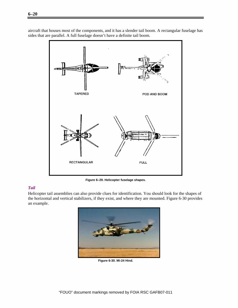
Engines and fuselage Next, you look for the engines. Helicopters are like fixed-wing aircraft in that they can be single- or multi-engine aircraft. Some have their engines enclosed in the fuselage, whereas others carry a pod assembly for their engines. Helicopter fuselages, figure 6-29, are generally broken down into four shapes: tapered, pod and boom, rectangular, and full. The tapered fuselage is shaped like a teardrop when viewed from the top or bottom. A pod and boom fuselage has a definite pod in the front of the
6–20
“FOUO” document markings removed by FOIA RSC GAFB07-011
aircraft that houses most of the components, and it has a slender tail boom. A rectangular fuselage has sides that are parallel. A full fuselage doesn’t have a definite tail boom.
Figure 6–29. Helicopter fuselage shapes.
Tail Helicopter tail assemblies can also provide clues for identification. You should look for the shapes of the horizontal and vertical stabilizers, if they exist, and where they are mounted. Figure 6-30 provides an example.
Figure 6-30. Mi-24 Hind.

6–21
“FOUO” document markings removed by FOIA RSC GAFB07-011
Repeating the process Be alert for new aircraft being introduced. Recognition training is continuous. It takes repetition to imprint the image in our minds. Also, remember to train with different views of the aircraft and vary the way it is presented. Recognition skills come with practice.
Your recognition training program should teach the aircrews to recognize aircraft quickly. The aircrews should be able to determine whether an aircraft is or is not a threat to them. You want aircrews to provide information in debriefings on the types of threat they encountered; but more importantly, you want the aircrews to come back alive.
Final objective Your aircrew members should be able to identify an aircraft shown on a slide within a glance. Most importantly, they should be able to identify the aircraft as either a threat or a non-threat, or as an ally or hostile. Your effort into your aircrew’s aircraft recognition training is the first step to a successful combat mission.
Self-Test Questions After you complete these questions, you may check your answers at the end of the unit.
228. Developing and presenting an aircraft recognition program 1. What does the acronym WEFT mean?
2. What is the method most widely used to teach aircraft recognition?
3. What is the method used to identify identify helicopter recognition?
4. Name the three different wing mount positions?
5. Small stabilizer appendages forward of the wing that provide increased stability to the aircraft are called what?
6-2. Naval Vessels 229. Naval vessel recognition Introduction While control of the combat skies is our mission, we must also be aware of the threats that can come from naval vessels. Your aircrews will also have to train on naval vessel recognition. One of the reasons you train on naval vessel recognition is because of the movement of the overall military toward more joint operations than ever before. We find ourselves interacting with the Navy in open ocean, sea surveillance, mine laying, and naval strike missions. The risks to your aircrews are increasingly greater, because of smaller countries spending more money on their defenses. The risks

6–22
“FOUO” document markings removed by FOIA RSC GAFB07-011
involved in your aircrew’s penetration of an enemy country along coastal waters have increased. As defense technology and newer air defense weapons systems spread throughout the world, our aircrews become more vulnerable to these threats.
General recognition features A ship may be considered a floating platform designed to carry certain fighting or logistics materials and the personnel required to handle them. Depending on its design and mission, a ship may be a sea-going weapons platform, an air base, a supply depot, or a means of transporting troops. Ships that are designed to perform a common task constitute a ship type. Ship types and functions can often be deduced from their general appearance, along with the weapons and equipment they carry. You should first become familiar with the basic nomenclature of warship recognition. Refer to figure 6-31 as you study the typical naval recognition and refer to the terms in figure 6-32.
Figure 6–31. Basic ship features.
Ship Features Description Stem (bow) The extreme foremost part of the ship’s hull; that portion which cuts the water.
The main deck of the bow section is called the forecastle.
Bridge superstructure This structure, which is usually located forward on the deck, contains control and visual communications stations and the station (bridge) of the officer commanding the ship. On carriers this structure is called an island.
Foremast The forward-most mast of a ship that has two or more masts. Ship masts may be vertical or raked. They may be heavy poles, tripods, pylons, or towers used to support radar, controls, or signaling equipment.
Stacks (funnel) The ship’s smokestacks, or funnels. Stacks may be in line, offset, side-by-side, or part of a mast and stack complex called a mack.
Main mast The second mast of a ship that has two or more masts.
Fantail The main deck area at the stern of the ship.
Stern (transom) The extreme aft or rear portion of a ship’s hull.

6–23
“FOUO” document markings removed by FOIA RSC GAFB07-011
Ship Features Description Main mounts The main mounts are the heaviest armament carried by a warship for its
mission. A main gun mount houses the largest caliber guns carried by a warship. Guns exceeding 6 inches are usually housed in turrets. Secondary armament refers to the next heaviest weapons carried by a warship.
Aft superstructure The rear or aft upper works or deck housing above the main deck; it usually does not extend the whole width of the ship.
Freeboard The vertical distance from the waterline to the lowest outside deck.
Deck line or hull line The profile configuration of the upper level of a ship’s hull. The hull line may be unbroken (flush), or it may be broken with downward steps, raises, or wells.
Deck The uppermost complete (continuous) deck is called the main deck. Weather decks are decks that are exposed to the weather. Elevated decks that do not extend the full width of the ship are superstructure decks. A partial deck at the bow is a forecastle deck. A partial deck amidships is a midcastle deck.
Figure 6-32. Ship features.
Identifying naval recognition features Aircrew naval vessel recognition training is normally presented using the mast, armament, stack, and hull (MASH) system. These four elements are normally the easiest recognition features for aircrews to sight.
Mast In pointing out the masts on a ship, tell aircrews the first thing to look for is how many masts there are, including foremasts, main masts, and aft masts. After that, they should consider the placement of the masts, such as amidships, aft of the forward superstructure, and so forth. Then point out the construction of the masts; they could be tripod, latticed, or enclosed.
Armament During vessel recognition training, you should cover each type of armament system, such as guns, rockets, missiles, aircraft, and so forth, that can be found on ships. Give the aircrews the designator for the primary and secondary systems, such as 5-inch guns, SS–N–22, SA–N–4, and so on. You should also tell the aircrews the basic mission of the armament: surface-to-air, surface-to-surface, ASW, and so forth. Point out the placement of the armament and the number of mountings. For example, there could be one single mount on the forecastle, or there could be one twin-armed launcher on the aft superstructure. Any other unique features of the armament, such as vertical launch, should also be pointed out.
Stacks If the ship has stacks, they should also be shown as a recognition feature. You should brief the number, their placement on the ship, their shape (vertical, tapered, raked, etc.), and any other distinguishing features.
Hull The hull configuration is also presented in your recognition briefing. You should brief the bow shape, the hull line, and the stern configuration. The superstructure configuration can also provide key recognition features, such as its placement, overall shape, and any other unique features.
Different classes of naval vessels Helicopter cruiser Generally, the mission of helicopter cruisers is to support antisubmarine warfare (ASW) and amphibious operations. They usually carry only helicopters and vertical short takeoff and landing (VSTOL) aircraft, and they normally do not have arresting gear or catapults. Their major recognition

6–24
“FOUO” document markings removed by FOIA RSC GAFB07-011
feature is an extensive flight deck, usually located aft, which accommodates helicopter pads. An illustration of how they might appear and their primary recognition features is shown in figure 6-33.
Figure 6–33. Helicopter cruiser.
Large amphibious class ship Some large amphibious ships bear a resemblance to helicopter cruisers because of size, extensive flight deck aft, and weaponry. The important clues for differentiating between them relate to the presence of cranes and other machinery, a fold-down ramp gate at the stern, and the number of helicopter pads aft. An example of such an amphibious ship is shown in figure 6-34. A true helicopter cruiser must accommodate 15 helicopters.
Figure 6–34. Large amphibious ship recognition features.
Destroyers This type of ship is considered a jack-of-all-trades. It fulfills an ASW role in a carrier force, forming a screen around the carrier. Guided-missile destroyers carry SAMs in addition to guns with which they protect the carrier from air strikes. Other destroyer types are designed for surface-to-surface gun fighting, torpedo attacks against larger ships, laying smoke screens, and shore bombardment, as well as secondary ASW roles. Destroyers are usually about 400 feet long and range from 3,500 to 4,000 tons in displacement. The usual configuration has superimposed main mounts forward (with 5-inch
6–25
“FOUO” document markings removed by FOIA RSC GAFB07-011
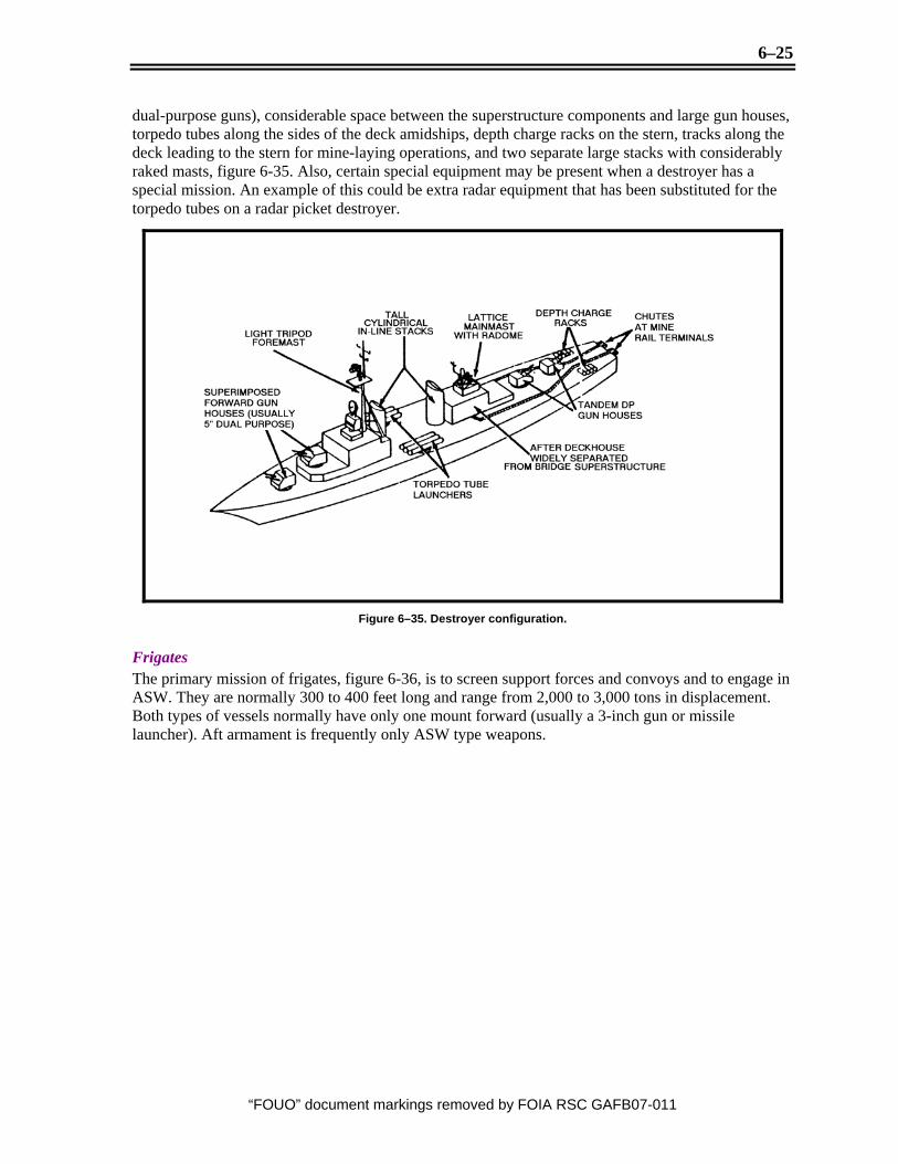
dual-purpose guns), considerable space between the superstructure components and large gun houses, torpedo tubes along the sides of the deck amidships, depth charge racks on the stern, tracks along the deck leading to the stern for mine-laying operations, and two separate large stacks with considerably raked masts, figure 6-35. Also, certain special equipment may be present when a destroyer has a special mission. An example of this could be extra radar equipment that has been substituted for the torpedo tubes on a radar picket destroyer.
Figure 6–35. Destroyer configuration.
Frigates The primary mission of frigates, figure 6-36, is to screen support forces and convoys and to engage in ASW. They are normally 300 to 400 feet long and range from 2,000 to 3,000 tons in displacement. Both types of vessels normally have only one mount forward (usually a 3-inch gun or missile launcher). Aft armament is frequently only ASW type weapons.

6–26
“FOUO” document markings removed by FOIA RSC GAFB07-011
Figure 6–36. Frigate recognition features.
Other vessels There are many smaller vessels that have specific functions and missions. Some examples of these smaller vessels are gunboats, figure 6-37, torpedo boats, figure 6-38, and patrol boats, figure 6-39. These vessels vary in size, and with a few exceptions, they are less than 200 feet long. Their function is usually supportive and defensive in nature along coastal lines.
Figure 6–37. Gunboat features.

6–27
“FOUO” document markings removed by FOIA RSC GAFB07-011
Figure 6–38. Torpedo boat features.
Figure 6-39. Patrol boat features.
Look-alike ships In briefing individual enemy ships, you need to include US or allied ships that have similar appearances. This problem is handled just like look-alike aircraft. You briefly cover the similarities of the two ships; then, brief the distinguishing features in their construction that make the two ships different.
Test the aircrews on their knowledge of naval vessel recognition the same way you test them for aircraft recognition. Show a slide for 5 to 10 seconds, and ask the aircrew members to identify it. It’s hard for the aircrew to identify any particular class of ship; but if they can identify the type, it’s usually considered sufficient.
Self-Test Questions After you complete these questions, you may check your answers at the end of the unit.
229. Developing a naval recognition program 1. What is the method used by aircrews to identify naval vessels?
6–28
“FOUO” document markings removed by FOIA RSC GAFB07-011
•
•
2. What is the extreme foremost part of the ship’s hull that cuts the water?
3. What type of vessel is generally less than 200 feet and normally found along costal lines?
4. When identifying the hull of a ship, what must be considered?
5. What are some of the points you should bring out when identifying a ships mast?
6-3. Ground Equipment 230. Ground equipment recognition Introduction Aircrew members are also tasked with recognition of ground equipment including tanks, APCs, MRLSs, SAMs and AAA. Again, your unit mission must be taken into consideration when you make decisions on what ground equipment your aircrews should be trained on. Your ground equipment recognition program should place emphasis on the equipment that poses a potential threat to the aircrew, aircraft, and mission accomplishment. For instance, AAA would not pose the same threat to a U–2 as it would to an A–10. Also, your recognition-training program must focus on ground equipment that may be potential targets during a mission, such as CAS, interdiction or suppression. Missiles, transporters, control and guidance systems, tanks, artillery, radar, and air defense sites outlines are examples of types of targeted ground equipment.
A successful ground recognition training program could not only help save the lives of your aircrews, but also friendly forces on the ground. Your aircrews’ ability to distinguish between enemy, friendly, or neutral country equipment will play a major role. Also remember that your aircrews’ are valuable intelligence collectors. Your recognition training gives them the ability to report information about the potential ground threats along their flight routes, as well as provide up-to-date information on the ground battle situation.
The following are offered as examples:
If Army commanders know their troops are going up against tanks instead of assault guns, they can plan accordingly. When they know the tanks are T–55s with 100-mm guns, rather than T–72s with 125-mm guns, their decisions will save even more lives. A pilot who flies ground attack missions and relies totally on which way the guns are pointing is just as likely to destroy friendly troops. On the other hand, it would not be logical to train aircrews who fly high-altitude reconnaissance missions to identify ground weapons. They would be fortunate to see the weapons.
Although we won’t go into specifics, your ground equipment recognition training might also include items such as trucks, military bulldozers, bridge laying equipment, and other such equipment. Again, check your MAJCOM directives to know exactly what must be included.
If your aircrews are flying over a battlefield at low level, they may be in prime position to see significant enemy equipment, which may lead to an advantage over the enemy. Ground equipment and the other recognition training we’ve discussed must be continuous to be effective. You can’t

6–29
“FOUO” document markings removed by FOIA RSC GAFB07-011
expect your aircrew members to be able to recognize all of the enemy equipment in your operating area after a 1-hour training session. Only by continual practice will the aircrew members become competent enough to accurately report on enemy equipment.
Tanks The recognition of tanks from the air is based primarily on their overall rectangular shape, length-width ratio of about 2 to 1, and the presence of a fully enclosed turret and gun. Figure 6-40 illustrates the features of a tank that might be observed from the air. Familiarize yourself with the terminology and refer to this figure as we discuss the recognition features. (NOTE: Identifying a particular model of tank from the air is very hard and takes repeated training.)
Figure 6–40. Tank recognition features.
Turret The turret is the most important feature for identification of a specific type of tank. The shape and position of the turret will, in most instances, enable you to recognize a specific tank or at least narrow the identification to a choice of two tanks. On current FSU tanks, the turrets are positioned either well forward or approximately centered on the hull. Three different turret shapes are normally used: round, teardrop, and hexagonal shapes. If seen, the hatches on the top of the turret can also aid identification. For example, two turret hatches—the commander’s hatch and the loader’s hatch—are present on most FSU tanks. The commander’s hatch is usually set in a cupola that is raised less than a foot above the turret top, and it is always located on the left side of the turret.

6–30
“FOUO” document markings removed by FOIA RSC GAFB07-011
Chassis The tank chassis presents a number of significant features that are characteristic of specific tanks. Probably the most apparent of these is the relationship of the fenders to the front and rear of the hull. On some tanks, the fenders extend beyond the hull; on others, the hull extends beyond the fenders; and on some, the fenders are flush with the hull. The engine compartment vents, which are located on the rear deck, are also significant recognition features. Although they usually appear rectangular in shape and are dark toned, their size and arrangement differ on the various tanks.
Gun Several aspects of a tank gun, such as the mantlet, the length of the gun tube, and the shape and size of external appendages, can also aid in tank identification. For example, mantlets used on FSU tanks are either internally or externally curved. The distance the gun tube extends beyond the hull can also help. Occasionally an aircrew can discern gun-tube appendages, such as a muzzle or reinforcing band, that can also aid in identification.
Self-propelled guns The primary identification features of self-propelled guns, figure 6-41, are the same as those for tanks, with one major exception. Most self-propelled guns have a fixed superstructure. Those few FSU self-propelled guns that do not have a fixed superstructure have a turret mounted to the rear of the chassis. The most reliable feature to use in identifying self-propelled guns is the superstructure. The position of the superstructure aids in identification, and the absence of an armored roof can also assist. The fender positions and engine compartment vents can also be a clue for the observer to identify the self-propelled guns.
Figure 6–41. Self-propelled-gun recognition.
Artillery Artillery is extremely difficult to recognize from the air because of its relatively small size and because of the efforts usually taken to conceal it. For this reason, during recognition briefings, you would normally point out associated features that may indicate the presence of artillery. Track activity is perhaps the most important of these features. Both vehicle and foot traffic, in an otherwise undisturbed area, often disclose individual gun emplacements and reveal the complete battery and command posts, even though the guns are not visible. Other indicators are soil (from preparation of

6–31
“FOUO” document markings removed by FOIA RSC GAFB07-011
emplacements), blast marks, crew shelters, ammunition storage, and prime movers. Some typical artillery emplacements and layouts are illustrated in figure 6-42.
Figure 6–42. Artillery emplacements and layouts.
Armored personnel carriers Armored personnel carriers (APC), figure 6-43, are lightly armored vehicles that have been designed primarily for use as reconnaissance vehicles and personnel carriers. They can be recognized by their angular appearance, the presence of armored windshield covers, and the absence of a driver’s cab. Their angular appearance is caused by their armor plate construction. The usual procedure of designating a category of vehicle by using a uniform set of recognition features cannot be easily applied to APCs. Each vehicle tends to have its own appearance, which makes it unique. Therefore, the aircrews’ recognition of a vehicle as being an APC and their identification of the particular model have to be almost simultaneous processes.

6–32
“FOUO” document markings removed by FOIA RSC GAFB07-011
Figure 6–43. Wheeled and tracked APCs.
Your aircrews have to be familiar with the recognition features of each of the APCs in your theater of operation. During your recognition briefing, you should emphasize the size and shape of the vehicles, rather than a comparison of similar features of each vehicle. An APC can be as large as a cargo truck, or it can be as small as a sedan. The vehicle may or may not have a troop compartment, which can be rectangular or angular in shape. And, the vehicle can be either wheeled or tracked.
Transporter-erector-launcher Transporter-erector-launchers (TEL) are the primary mobility elements for tactical surface-to-surface missile (SSM) and SAM systems. There are no generic recognition features you can point out to the aircrews. Each TEL has its own individual recognition features. It could be a tracked vehicle, or it could be wheeled. About the only similarity the TELs have is the fact that they all carry missiles. Figure 6-44 shows you an example of a TEL.
Figure 6–44. Transporter-erector-launcher.
Antiaircraft artillery and surface-to-air missile sites Another area you normally include in your ground equipment recognition training is AAA and SAM sites. These sites are almost invariably found near objectives of military importance. They are there to protect targets, such as bridges, ammunition dumps, headquarters areas, and airfields. Entire cities

6–33
“FOUO” document markings removed by FOIA RSC GAFB07-011
may be protected by belts of AAA or SAM batteries. Individual sites are established according to the terrain and the probable altitude of attacking aircraft, and they will generally be limited to those areas that are easily accessible by roads. They are normally placed in an open area, because any restriction on the field of fire affects the number of rounds that can be fired at a given time.
An example of an AAA site configuration is shown in figure 6-45. Note the cable trench or scars connecting the fire control radar to the junction box, fire director, and the individual weapon positions. The presence of these trenches or scars indicates that the site has fire control radar and a central fire control system, which means that the weapons are either medium or heavy AAA.
Figure 6–45. Typical AAA site.
SAM sites have a dispersed pattern also. Individual patterns and associated electronic equipment provide the recognition features for aircrews.
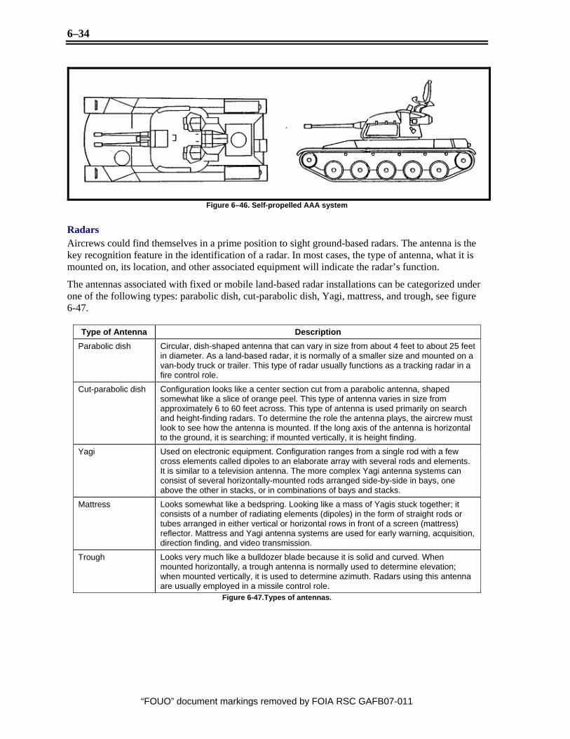
Self-propelled antiaircraft artillery Self-propelled AAA weapons should also be included in your recognition briefing. These weapons are found most often near the FEBA, because their mobility is of great value in a dual role against land and air targets. These vehicles look similar to a completely covered APC that has multibarreled guns protruding from a turret. Figure 6-46 provides an illustration of a self-propelled AAA system.
6–34
“FOUO” document markings removed by FOIA RSC GAFB07-011
Figure 6–46. Self-propelled AAA system
Radars Aircrews could find themselves in a prime position to sight ground-based radars. The antenna is the key recognition feature in the identification of a radar. In most cases, the type of antenna, what it is mounted on, its location, and other associated equipment will indicate the radar’s function.
The antennas associated with fixed or mobile land-based radar installations can be categorized under one of the following types: parabolic dish, cut-parabolic dish, Yagi, mattress, and trough, see figure 6-47.
Type of Antenna Description Parabolic dish Circular, dish-shaped antenna that can vary in size from about 4 feet to about 25 feet
in diameter. As a land-based radar, it is normally of a smaller size and mounted on a van-body truck or trailer. This type of radar usually functions as a tracking radar in a fire control role.
Cut-parabolic dish Configuration looks like a center section cut from a parabolic antenna, shaped somewhat like a slice of orange peel. This type of antenna varies in size from approximately 6 to 60 feet across. This type of antenna is used primarily on search and height-finding radars. To determine the role the antenna plays, the aircrew must look to see how the antenna is mounted. If the long axis of the antenna is horizontal to the ground, it is searching; if mounted vertically, it is height finding.
Yagi Used on electronic equipment. Configuration ranges from a single rod with a few cross elements called dipoles to an elaborate array with several rods and elements. It is similar to a television antenna. The more complex Yagi antenna systems can consist of several horizontally-mounted rods arranged side-by-side in bays, one above the other in stacks, or in combinations of bays and stacks.
Mattress Looks somewhat like a bedspring. Looking like a mass of Yagis stuck together; it consists of a number of radiating elements (dipoles) in the form of straight rods or tubes arranged in either vertical or horizontal rows in front of a screen (mattress) reflector. Mattress and Yagi antenna systems are used for early warning, acquisition, direction finding, and video transmission.
Trough Looks very much like a bulldozer blade because it is solid and curved. When mounted horizontally, a trough antenna is normally used to determine elevation; when mounted vertically, it is used to determine azimuth. Radars using this antenna are usually employed in a missile control role.
Figure 6-47.Types of antennas.
6–35
“FOUO” document markings removed by FOIA RSC GAFB07-011
Self-Test Questions After you complete these questions, you may check your answers at the end of the unit.
230. Developing a ground equipment recognition program 1. When identify tanks from the air, recognition is based primarily on what?
2. The primary identification features of self-propelled guns are the same as those for tanks, with one major exception. What is that exception?
3. AAA and SAMs are difficult to distinguish from the area. However, What one common trend do these systems possess?
4. What weapons system looks very similar to an APC, but has multi-barrelled guns protruding from the turret?
Answers to Self-Test Questions
228 1. Wings, engine, fuselage, tail. 2. Total form concept. 3. Rotors, engine, fuselage, and tail (REFT). 4. Low, mid, high. 5. Canards.
229 1. Mast, armament, stack, and hull (MASH). 2. Bow. 3. Gun boats, Patrol Boats, Torepedo Boats. 4. You should brief the bow shape, the hull line, and the stern configuration. 5. How many masts there are, including foremasts, main masts, and aft masts. Consider the placement of the
masts, such as amidships, aft of the forward superstructure, and so forth. Point out the construction of the masts; tripod, latticed, or enclosed.
230 1. Based primarily on their overall rectangular shape, length-width ratio of about 2 to 1, and the presence of a
fully enclosed turret and gun. 2. Most self-propelled guns have a fixed superstructure. 3. Typical patterns of set-up. 4. Self-propelled AAA.