unit 04 common processes and techniques ac 4 describe ......unit 04 common processes and techniques...
TRANSCRIPT

Unit 04 Common processes and techniques
AC 4 Describe methods of jointing pipework used in dwellings OK, we’ve looked at the various types of pipes and the range of fittings; let’s take a look at how we put them together. Here’s a list of what we’re going to cover:
Copper pipe Integral solder ring and end feed Compression (type A and B) Push-fit Press-fit
Low Carbon Steel (LCS)
Threaded
Plastic pressure pipe
Push-fit
Compression
Proprietary – copper and MDPE
Plastic sanitation pipe Push-fit Compression Solvent welded
Copper pipe
Integral solder ring and end feed
The process is fairly straight forward for both types of fitting; we’ll start with the integral solder ring.
Best results are obtained when joints are heated as soon as possible after assembly. After heating and subsequent cooling, flush the system, preferably with hot water. Ensure adequate ventilation when heating the joint.
Any joints not heated during the working day should be dismantled, cleaned and refluxed prior to
reassembly.
Select the correct size of tube and fitting for the job. Ensure that both are clean, in good condition and free from damage and imperfections. If the tube is oval or damaged use a re-rounding tool. Integral solder ring fitting Preparation

Unit 04 Common processes and techniques
1. Cut the tube square using a rotary tube cutter
wherever possible. If a hacksaw is used to cut the tube, a fine toothed blade should be used.
2. Remove any burr from the inside and outside of the tube ends using a fine toothed file or a de-burring tool.
3. Clean the inside of the fitting socket and the
outside of the tube with steel wool or a cleaning
pad.
Jointing
4. Using a suitable brush, apply adequate, but not
excessive, flux to both the outside surface of the tube and the inside surface of the fitting socket. Do not use your finger.
The reliability of soldered joints is affected by the type of flux used. Yorkshire flux and Traditional Craftsman’s flux are specially formulated for jointing copper tubes with Yorkshire integral solder ring fittings.
All fluxes are, to some extent, corrosive, but special care should be taken with so-called self-cleaning fluxes. Yorkshire flux is not suitable for gas applications.
5. Insert the tube into the fitting until it reaches the
tube stop, then wipe off any excess flux. Heat the assembled joint until a complete ring of solder appears at the mouth of the fitting.
6. Allow the joint to cool without moving it. Clean the joint generally, wiping off any external flux residues. This will prevent unsightly stains or (in extreme cases) corrosion of pipework. Flush out the pipework.

Unit 04 Common processes and techniques
This link takes you to all the literature on Yorkshire fittings, click on the link to ‘brochures’. Open the PDF document and take a look. You don’t have to read it all as we’ll cover some of its content (such as valves etc.) later. Please download the PDF and keep it in your folder. http://www.pegleryorkshire.co.uk/EN/Literature/Brochures/Brand?brand=Yorkshire
End feed fitting
The procedure for jointing an end feed fitting is the same as stages 1 to 4 for the integral solder ring,
so let’s pick up on the jointing process.
Jointing process
5. Insert the tube into the fitting until it reaches the tube stop, and then wipe off any excess flux. Heat the assembled joint evenly on all sides.
6. Apply solder (lead free) to the mouth of the fitting. When the correct temperature has been reached the solder will flow freely and be drawn into the joint. Briefly reapply the blowtorch and wipe off any excess solder
7. Allow the joint to cool generally, wiping off any
external flux residues. This will prevent unsightly stains or (in extreme cases) corrosion of pipework. Flush out the pipework.
This link takes you to all the literature on Endex fittings, as previously with Yorkshire fittings, click on
the link to ‘brochures’. Open the PDF document and take a look.
You don’t have to read it all as we’ll cover some of its content later, and don’t worry about end brazed fittings, they’re not used in domestic plumbing. Please download the PDF and keep it in your folder. http://www.pegleryorkshire.co.uk/EN/Literature/Brochures/Brand?brand=Endex

Unit 04 Common processes and techniques
Note on fluxes:
Remember your health and safety unit, fluxes are subject to the requirements of the Control of Substances Hazardous to Health (COSHH) regulations. COSHH sheets regarding fluxes for Peglar Yorkshire are available to download from: http://www.pegleryorkshire.co.uk/EN/Corporate/Environmental There are other fluxes on the market, including self-cleaning fluxes, also known as ‘active fluxes’ as they clean the copper tube and fitting as the joint is being heated; the means they don’t have to be cleaned in the normal way beforehand (i.e. use of wire wool etc.). Some of these fluxes contain hydrochloric acid, which can be harmful and corrosive if not used correctly. Thorough flushing therefor is essential to remove any flux residue. There’s more information on this link: http://www.laco.com/soldering-fluxes/regular-flux-paste/
Compression (type A and B) Non-manipulative (Type A) Firstly, select the correct size of tube and fitting for the job. Ensure that both are clean, in good condition and free from damage and imperfections. If the tube is oval or damaged, use a re-rounding tool. Copper tube for type A compression fittings should be of half-hard (R250) or hard (R290) temper. Preparation
1. Cut the tube square using a rotary tube cutter wherever possible. If a hacksaw is used to cut the tube, a fine toothed blade should be used.
2. Remove any burr from the inside and outside of the tube ends using a fine toothed file or a deburring tool.
Jointing
3. There are two methods of assembling a compression joint.
4. A. Insert the tube firmly into the compression fitting, ensuring that the compression ring seats centrally and that the tube makes firm contact with the tube stop in the body of the fitting.
A
B

Unit 04 Common processes and techniques
5. B. Remove the compression nut and compression
ring, then put the nut and then the ring on the tube. Insert the tube end up to the fitting's tube stop. Slide the ring and the nut down to the fitting body.
6. Tighten the nut using your fingers until tight.
7. Tighten the nut further using high quality open ended or adjustable spanners. Spanner flats are incorporated into the design of the fitting bodies. The second spanner must be used to prevent the fitting rotating as the nut is tightened.
For normal joint making, tighten the nut 1 turn (360°) for fittings in sizes from 6mm to 12mm, or 3⁄4 turn (270°) for fittings in sizes from 15mm to 54mm.
A few drops of light oil on the threads will assist, especially on sizes 35mm and above. When jointing stainless steel or R220 copper tube some variation may be needed; the nut may be tightened further if necessary. Take care not to over tighten the compression nut, as this will not result in a stronger joint and could lead to problems when in use.
Manipulative (Type B)
Type B, or manipulative fittings are used with soft (R220) copper tube and require the plumber to flare the tube end before the joint is assembled. A hacksaw should be used to cut the tube; a tube cutter must not be used for this task as it could easily misshape the end of the tube. All jointing surfaces must be kept clean throughout the process. Following preparation of the fitting and tube, the assembly is carried out as follows:
1. Slip the compression nut and compensating ring over the tube.
2. Flare the end of the tube using a clean forming tool of the correct size by dealing a few blows with a hammer. This operation can be made easier with the use of a few drops of light oil.
2

Unit 04 Common processes and techniques
3. Insert the parallel end of the adaptor piece in the fitting socket and locate the flared tube end onto the tapered face of the adaptor piece.
4. Slide the ring and the nut down to the fitting body and first tighten by hand. Then, using spanners, tighten the nut one full turn. This is generally sufficient to provide a sound, leak-proof joint.
This link will take you to the Kuterlite brochure and information about compression fittings. as previously with the Peglar Yorkshire website, click on the link to ‘brochures – Kuterlite Compression Fittings’. Open the PDF document and take a look. You don’t have to read it all as we’ll cover some of its content later such as valves etc., but please download the PDF and keep it in your folder. http://www.pegleryorkshire.co.uk/EN/Literature/Brochures/Brand?brand=Kuterlite
Push-fit The jointing procedures are almost identical for every type of push-fit fitting and compatible tube material. Where there are variations (such as inserting a liner into a PEX pipe) these will be shown later, but for now we are focussing on copper. To ensure the fittings stay clean and the ‘O’ ring is protected from damage, never remove the fitting from its packaging until immediately prior to installation. The tube/pipe can be fully inserted by hand. A damaged tube/pipe end will require excessive force to be used. If this is the case you should check the tube/pipe is round and deburred before continuing. Push-fit fittings with plain male ends must not be used directly with capillary fittings, since heating will damage the non-metallic parts. Neither should plain ends on capillary fittings be used with push fit fittings. Heat should not be applied to push-fit fittings, directly or indirectly. They should be disconnected (where applicable) to avoid any possible damage to non-metallic parts if they are to be used on a system in conjunction with capillary fittings. Similarly, reconnection must not be considered until the heated tubes have been allowed to cool and have been flushed to remove any flux residues. Use pipe clips to secure finished installations and prevent vibration or movement.
4
3

Unit 04 Common processes and techniques
Fittings can be painted with water-based paints. Oil-based or aggressive solvent paint should be avoided. Preparation Select the correct size of tube and fitting for the job. Ensure both are clean, in good condition and free from damage, scores and imperfections. Do not use any additional lubricant or sealing compounds. Cut the tube square using a rotary tube cutter wherever possible. Take care to ensure that the tube end is deburred and chamfered. If the tube is oval or damaged, use a re-rounding tool. New tube ends should have any tape, labels or residual (remaining) adhesive removed, taking care not to damage the tube in the process. Check the tube is round, clean and free from burrs and scores. We recommend the use of a good quality tube cutter with a sharp wheel for copper tube. If you use a hack saw, make sure the pipe end is square and de-burred Burrs can be removed using a purpose made tool as shown on the left, as well as deburring, this also acts as a scribe tool and socket depth marker. If you use a hack saw, then use a file to remove the burrs as shown on the right. To make a perfect joint, the tube must be fully inserted in the fitting until it meets the tube stop. To confirm that this is the case, mark the socket depth on the tube or pipe using a socket depth marker as shown to the right (this is similar to the one above left). The socket depth of each size of fitting can be found in the manufacturers tables. The socket depth can occasionally be obscured by the collar of the fitting so we recommend adding a ‘V‘ mark over the depth mark line as this will always be visible.
Tube cutters
Hack saw

Unit 04 Common processes and techniques
Jointing
1. To make a perfect joint, the tube or pipe must be fully inserted in the fitting until it meets the tube stop. As mentioned, to confirm that this is the case, mark the socket depth on the tube or pipe using the appropriate socket depth marker or a tape measure and a marker/pencil.
2. Inspect the fitting ensuring that the grab rings/‘O’-rings have not been contaminated with grit or debits. Insert the tube/pipe into the mouth of the fitting to rest against the grab ring.
3. Push the tube firmly with a slight twisting action until it reaches the tube stop with a positive ‘click’.
4. Ensure the depth insertion mark corresponds with the mouth of the fitting and then pull firmly on the tube to ensure the fitting is secure.
Note: Pegler Yorkshire recommend all systems are thoroughly pressure tested to 1.5 times working pressure before the hand-over to the customer. This type of push-fit fitting is not suitable for use on gas services, and will only provide electrical continuity when installed with metal tube. You can download the technical information regarding push-fit fittings as supplied by Pegler Yorkshire. Please take time to look through the information and in particular the socket depths on page 105. http://www.pegleryorkshire.co.uk/EN/Literature/Brochures/Brand?brand=Tectite
Activity 12
Some types of push-fit fittings are demountable, which means they can be disconnected and re-used. Using the link we’ve given you above, read up on the demountable fittings on page 110 and make a few bullet point notes in your course folder. Remember, there may be a question later!

Unit 04 Common processes and techniques
Press-fit Ok, so far in terms of copper tube jointing techniques we’ve covered:
Solder ring and end feed
Compression (type A and B)
Push-fit Now we’ll take a look at press-fit fittings and the installation instructions for domestic applications. 1. Check the fitting Keep all fittings in their bag prior to installation to ensure the lubrication does not dry out. Ensure the ‘O’ ring is seated correctly within the fitting socket. 2. Cut the tube square It is essential to cut the tube square using a rotary tube cutter. 3. De-burr and check the tube ends Both the internal and external tube ends should be deburred then wiped clean of all swarf and debris to avoid damage to the ‘O’ ring upon tube insertion. Also check that the tube end is clean and free from damage such as scores, tape, labels or adhesive residue. The image shows a purpose made de-burring tool for inside and outside of the pipe. If you use a hacksaw then use a file to de-burr. 4. Mark the socket depth Ensuring full socket depth is achieved is vital for the integrity of the joint. To check that the tube and fitting remains in the correct position throughout the pressing process you must mark the socket depth with a ‘V-Tail’ mark. Alternatively you can do by hand using a tape measure.
Socket depth tool coloured orange for copper

Unit 04 Common processes and techniques
5. Assemble the joint Insert the tube into the fitting until it meets the tube stop, using the insertion depth mark as a visual aid. Only when the tube reaches the tube stop should the pressing operation be commenced. 6. Prepare the press-fit tool Select the correct combination of press-tool and jaws for the joint being made. Note: Always refer to the manufacturer’s instructions for detailed information on how to operate the press-tool safely. Check that the press tool and relevant jaws have been maintained in accordance with their servicing/calibration schedule. Make the tool safe by isolating it from the power supply. Select the correct jaws for the joint being made, checking that they are free from damage. Attach the jaws to the press-tool, following the instructions for your particular press-tool, and reconnect the power supply when ready. 7. Manufacturer’s Dri-slide lubricant Use of manufacturer’s Dri-Slide lubricant is essential when jointing large sized fittings. 8. Press the joint Mount the jaws over the bead at the mouth of the fitting. With the tool fully supported and not hanging from the pipework, and with your hands safely away from the joint, press the trigger or button to start the jointing cycle. When the jaws fully enclose the mouth of the fitting, the joint is complete. The jaw should then be released from around the fitting. Note: Maintain a 90° angle between the tube and jaws at all times, this is to ensure the integrity of the joint as well as protect the operator from ‘kickback’. The pressing operation should only be carried out when the tube is adequately supported by brackets, not when the tube is suspended in the fitting socket alone. Allow press-fit jaws to be attached without hindrance.

Unit 04 Common processes and techniques
9. Check the joint Inspect the finished joint making sure all is in order, when satisfied the joint has been made correctly mark the joint as complete. The socket depth mark you made indicates that full socket depth has been maintained throughout the pressing cycle. The fitting and pipe bear the witness marks from your jaws. We recommend all systems are thoroughly pressure tested before hand over to end user.
Here’s a link to the Tectite brochure, as previously with the Peglar Yorkshire website, click on the link to ‘brochures – Tectite Metal Push-fit’. Open the PDF document and take a look.
You don’t have to read it all as we’ll cover some of its content later such as systems, PEX pipe, etc.,
but please take a look at the information on demountable fittings and how they work. Download the
PDF and keep it in your folder.
http://www.pegleryorkshire.co.uk/EN/literature/brochures/Brand?brand=Tectite
You can see video clips on the jointing method of all the copper tube jointing applications by
following the link. You need to look at:
Yorkshire
Endex
Kuterlite
Tectite
Xpress
http://www.pegleryorkshire.co.uk/EN/VideosAndTraining/Videos
These videos tend to show jointing techniques for a full range of fitting sizes, but remember for domestic plumbing we’re only looking at sizes up to 28mm. The Tectite video also shows methods of jointing PEX or PB pipe, stainless and carbon steel. Please take time to view all the videos.
As well as viewing the videos, we would like you take notes of any points you think are important and then record them in your course folder.
That completes copper pipe jointing; next we’ll take a look at how to joint LCS.

Unit 04 Common processes and techniques
Low carbon steel (LCS) pipe jointing All the following images and videos under this section have been reproduced with the kind permission of Ridgid, we have provided a number of links to their website within the text. For domestic installations, where we talking about sizes of ½”, ¾” and 1”, there are two main jointing methods:
Threaded joints
Compression joints Threaded joints Jointing LCS pipe can be done by cutting threads into the end of the LCS pipe to give a British Standard Pipe Thread (BSPT), then jointing them together with a range of female threaded fittings made from steel or malleable iron. The threads are cut using stocks and dies, the stocks being the body and handle of the tool, the dies being the actual cutter. The following steps indicate the process for creating a threaded joint on LCS pipework.
The LCS pipe is cut to length using heavy duty pipe cutters, the pipe being held secure in a vice. (The LCS pipe can also be cut using a large frame hacksaw.)
Remove any burrs from the inside and outside of the pipe, you can use a purpose made tool like the one shown or alternatively, use a file
If you use a hacksaw to cut the pipe, you’ll need to chamfer the end of the pipe that’s being threaded to provide a leading edge for the dies to catch the pipe wall
Set up stocks and dies (the photograph to the right shows a typical set-up)
Heavy duty pipe cutters
Pipe de-burring tool
Pipe vice
Manual ratchet threader
Stock
Dies
Unit 04 Common processes and techniques
Cutting compound or cutting oil should be applied to the end of the pipe before commencing the thread cutting operation. The thread should be cut so that it is approximately 1 to 2 threads longer than the length of the inside of the fitting; these additional threads are termed ‘stress threads’
Once completed, the excess cutting compound is wiped off
Appropriate threaded pipe sealants and paste types will depend on the pipe installation use, manufacturer’s instructions or a specification provided for the job.
Jointing methods for domestic installations include hemp and paste (not to be used on gas pipework installations), PTFE sealing tape, or gas thread sealing tape, which can then be applied to the thread. The fitting is then screwed in place
The pipe and fitting are joined together using adjustable pipe grips e.g. stilsons. Note: a short length of pipe can be placed over the grips handle if necessary, to give greater leverage when tightening.
If you’re fortunate enough to secure work placement with a plumber, ask for a demonstration as to the use of stocks and dies - this is the best way to learn! You can see a video demonstration of pipe threading techniques using a ratchet threader. This is on 2” pipe but is the same principle for smaller diameters. The demonstration is shown without the use of gloves; we would recommend the use of latex gloves in a working environment. Please take time to view this video. There are some other links after that video that you may also
find interesting. As well as viewing the videos, we would like you take notes of any points you think
are important and then record them in your course folder. Follow the link and click on video.
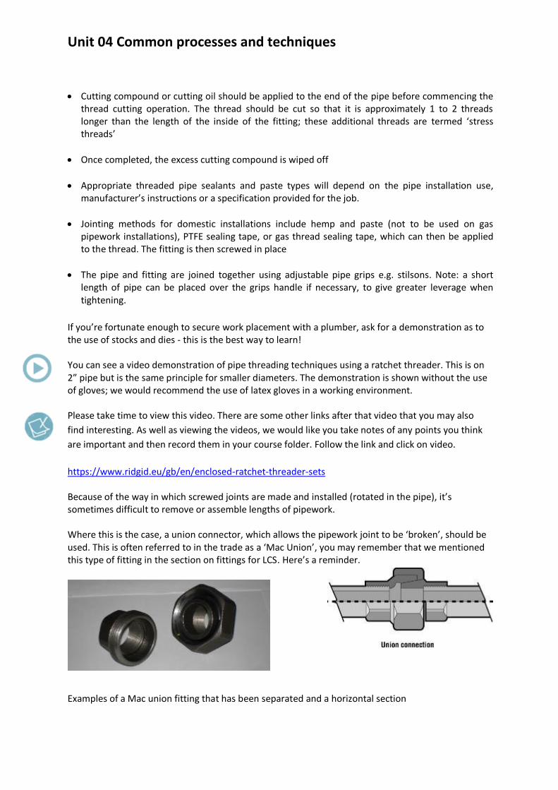
https://www.ridgid.eu/gb/en/enclosed-ratchet-threader-sets Because of the way in which screwed joints are made and installed (rotated in the pipe), it’s sometimes difficult to remove or assemble lengths of pipework. Where this is the case, a union connector, which allows the pipework joint to be ‘broken’, should be used. This is often referred to in the trade as a ‘Mac Union’, you may remember that we mentioned this type of fitting in the section on fittings for LCS. Here’s a reminder. Examples of a Mac union fitting that has been separated and a horizontal section

Unit 04 Common processes and techniques
Use of pipe threading machine Portable pipe threading machines, like the one shown (or larger static versions you may use in a college or training centre) provide a quicker and easier method of forming threads for LCS pipes. The machine is an ‘all in one’ combined pipe cutter and de-burring reamer, also comprising stock head and dies. There are a number of short videos on threading machines on this link, please take time to check them out. The videos shows threading for large diameter pipes, but it’s the same principle for smaller diameter pipe sizes. https://www.ridgid.eu/gb/en/1224-threading-machine Follow the link and click on videos. Compression joints There are a number of manufacturers’ designs for compression joints. Here’s a typical example: The fitting is designed to enable steel pipes to be joined without threading. Made of malleable iron, they use locking rings and seals which are tightened onto the pipe. They can be used on water and gas supplies, and although more expensive than threaded joints, they do save time on installation.
Compression fitting for LCS
Section through compression fitting

Unit 04 Common processes and techniques
OK that covers LCS jointing; next we’ll move onto the jointing of plastic pipes.
Jointing plastic pipes Previously we’ve looked at various types of joints for the different types of plastic pipe and what they are used for in the plumbing industry, which is, in the main, for either pressure or sanitation systems. Jointing techniques for plastic fall into four main categories:
Push-fit
Compression
Solvent weld
Proprietary – copper and MDPE
Next, let’s take a look at the jointing techniques for each type of plastic.
Jointing methods for polyethylene (MDPE) pipe
Activity 13
Can you remember the main use for MDPE in the plumbing industry, the sizes used in domestic plumbing, the colour of the pipe and the three main methods of jointing MDPE? Put your answer in the box provided.
Compression fittings made from brass
Preliminaries
Select the correct size, type and class of polyethylene pipe, and ensure it is appropriate to the application. Pipe support liners should also be of the correct size and class.
Preparation Cut the pipe to length using a hacksaw with a fine-toothed blade or pipe shears, ensuring the end is cut square.
Remove any burr from the inside and outside of the pipe ends with a sharp trimming knife. Ensure the threads of the fitting body and nut are free of dirt and grit.
Unit 04 Common processes and techniques
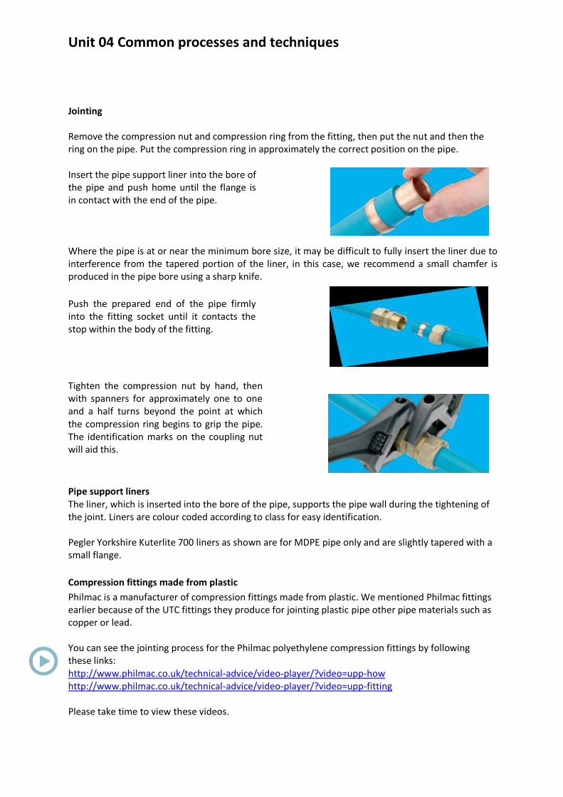
Jointing Remove the compression nut and compression ring from the fitting, then put the nut and then the ring on the pipe. Put the compression ring in approximately the correct position on the pipe. Insert the pipe support liner into the bore of the pipe and push home until the flange is in contact with the end of the pipe. Where the pipe is at or near the minimum bore size, it may be difficult to fully insert the liner due to interference from the tapered portion of the liner, in this case, we recommend a small chamfer is produced in the pipe bore using a sharp knife.
Push the prepared end of the pipe firmly into the fitting socket until it contacts the stop within the body of the fitting.
Tighten the compression nut by hand, then with spanners for approximately one to one and a half turns beyond the point at which the compression ring begins to grip the pipe. The identification marks on the coupling nut will aid this.
Pipe support liners The liner, which is inserted into the bore of the pipe, supports the pipe wall during the tightening of the joint. Liners are colour coded according to class for easy identification. Pegler Yorkshire Kuterlite 700 liners as shown are for MDPE pipe only and are slightly tapered with a small flange.
Compression fittings made from plastic
Philmac is a manufacturer of compression fittings made from plastic. We mentioned Philmac fittings earlier because of the UTC fittings they produce for jointing plastic pipe other pipe materials such as copper or lead. You can see the jointing process for the Philmac polyethylene compression fittings by following these links: http://www.philmac.co.uk/technical-advice/video-player/?video=upp-how http://www.philmac.co.uk/technical-advice/video-player/?video=upp-fitting Please take time to view these videos.

Unit 04 Common processes and techniques
Push-fit fittings made from plastic
Push-fit fittings are another alternative for joining MDPE pipe and simply push onto the pipe to make a secure watertight joint without the need for tightening. It’s necessary to use a nylon insert inside the pipe and then a fitting containing a neoprene rubber seal, together with a stainless steel grab ring is used to make the joint, OK, that covers polyethylene; let’s take a look at polybutylene.
Jointing methods for polybutylene (PB-1) pipe
The jointing methods we’re looking at here are:
Push-fit fittings
Standard Type A non-manipulative compression fittings
Push-fit fittings
These types of fittings are used on hot and cold water and central heating systems and for domestic plumbing have a size range of 10, 12, 15, 22 and 28mm. Previously we’ve shown you the fittings from Wavin’s Hep20 range, so now we’re going to show you the jointing techniques from the same product. Hep20 barrier pipe should be used on central heating systems. Always use recommended cutters to cut Hep2O pipe Calculate the correct pipe length, cut the pipe at one of the cutting marks ‘^’ printed onto the pipe. The distance between the ‘^’ marks is the insertion depth into the fitting and this should be allowed for.
Don’t use a hacksaw to cut Hep2O pipe. Don’t use damaged pipe. Ensure pipe ends are free from burrs and surface damage. If not, re-cut the pipe.
Cut the pipe squarely at one of the ‘^’ marks using recommended pipe cutters and ensure the pipe end is free from burrs.

Unit 04 Common processes and techniques
Insert a Hep2O SmartSleeve™ pipe support sleeve into the pipe end as shown below.
All O-ring seals contained in Hep2O fittings have been pre-lubricated during factory assembly and during normal installation, so additional lubrication should not be required. If the fitting has been used previously or if fittings have been un-bagged for several weeks, then the lubricant may have been removed or dried out and may require replacing. In these situations Hep2O Jointing Lubricant Spray must be used to avoid contravention of Water By-laws and ensure compatibility with other system materials. Don’t use other manufacturer’s lubricant or any alternative.
Push the pipe firmly into the fitting, then use Hep2O’s unique In4Sure™ joint recognition technology to ‘feel’ if the pipe is fully inserted
Tug back on the pipe to ensure the grab-ring engages correctly and prevents the pipe withdrawing
In4Sure™ technology
Push pipe firmly into fitting

Unit 04 Common processes and techniques
Activity 14
Please follow the next link, ther5e are a number of videos showing you how to joint and dismount
push-fit fittings, once on the page click onto the ‘videos and images’ button:
http://www.wavin.co.uk/web/solutions/potable-water/plumbing-systems/pushfit.htm
Make sure you view the jointing and dismounting video first as it follows on from the text. Then
take time to view the other videos; do this as many times as you like until you get a feel of the push-
fit product.
Standard Type A non-manipulative compression fittings
These fittings are manufactured to BS EN 1254: 1998 and because polybutylene is manufactured in
the same diameters as copper tube it’s possible to use type A compression fittings. The thing to
remember here is to make sure that a pipe insert is used inside the tube.
We covered this before on the session on fittings; can you remember why this is?
It’s because polybutylene pipe is too soft to support the olive being squeezed onto it and the insert
supports the pipe wall.
In terms of the jointing process using Hep20, it’s as follows:
Cut the polybutylene pipe using manufacturer’s recommended cutters, don’t use a hacksaw
Insert the liner
Follow the same procedure as that for jointing polyethylene pipe with compression fittings
(apply PTFE tape if required as shown.).

Unit 04 Common processes and techniques
Note:
Don’t use oil based jointing compounds
Always use an appropriate SmartSleeve™ pipe support sleeve
Use copper olives in preference to brass
Hep2O pipe will not rotate in a compression fitting after tightening
You can find out more about the installation of polybutylene pipe by downloading Wavin’s Hep20
installation guide from this link: http://www.wavin.co.uk/web/solutions/potable-water/plumbing-
systems/pushfit.htm
Click on the link and then click onto the ‘downloads’ link and then onto the ‘installer guide’ link on
the web page (there are two links, it doesn’t matter which you choose).
Please download the PDF, have a look at the jointing processes and then save the file for future
reference.
That takes care of polybutylene, next we’ll look at PVC-u, MuPVC and ABS.
Jointing methods for PVC-u, MuPVC and ABS
There are two ways of jointing PVC-u, MuPVC and ABS:
Push-fit, used on soil and vent pipes
Solvent welded, used on soil and vent pipes, waste pipes and overflow pipes.
Activity 15 The images below show the two methods of jointing PVC-u, MuPVc and ABS pipe and these are, push-fit and solvent welded. We would like you to follow this link, click on to the ‘downloads’ link and then onto the ‘Product and Installation Manual – Osma Soil and Waste’: http://www.wavin.co.uk/web/products/waste-water/soil-waste/waste-traps-osma/osmaw-abs-pipe-gy-32-l4-pe.htm The images below show some of the stages in the jointing process for push-fit joints. Using the Product and Installation Manual, please provide a brief explanation of what each stage of the process is.

Unit 04 Common processes and techniques
Push-fit jointing methods Place your answers in the boxes provided, expand the boxes if needed; we’ve given you and example to start you off.
Push-fit jointing method 1. Cut the pipe cleanly at right angles to its axis (image 1)
1. Cut pipe square
2. Chamfer and de-burr spigot
3. Ring seal joint

Unit 04 Common processes and techniques
Solvent welded jointing methods Using the Product and Installation Manual, jot down the methods for completing solvent welded joints, again we’ve given you an example to start you off. Hope that activity went well, that covers the jointing methods for PVC-u, MuPVC and ABS, the final plastic material to consider is polypropylene.
Solvent welded jointing method 1. Before using any solvent based cleaners or cement:
Read instructions carefully
Ensure there is sufficient ventilation

Unit 04 Common processes and techniques
Jointing methods for polypropylene (PP) You may recall from the section on plastic fittings, that polypropylene is used mainly for overflow pipe and waste pipe systems, (although it’s also used in plumbing for other items such as cold water storage cisterns and WC siphons). In terms of waste pipe systems, polypropylene cannot be solvent welded so the process used for jointing pipework is push-fit fittings. Just as a reminder, here’s an example of a PP fitting in grey plastic clearly showing you the ‘O’ ring joint. It’s the same procedure as the PVC-u etc. push fit joints really.
Cut pipe to length using a hacksaw and make sure that it is square
File off any burrs and chamfer the end of the pipe
Apply lubricant to the pipe and fitting
Ease the pipe into the fitting and past the ‘O’ ring to the end of the socket
Mark position of fitting on pipe
Withdraw pipe by 12mm to allow for thermal expansion
That covers everything on AC4, which is quite a bit! We’re moving onto bending pipework next, but before we do, let’s take a moment to recap on what we’ve covered on jointing pipework.

Unit 04 Common processes and techniques
Quick recap
Activity 16
We started with a summary of all the jointing methods for the various types of materials, can you recall what they were? Have a go at listing them under the following headings, if you can’t remember navigate back to pages earlier in the session to help you out.
Copper pipe
Low Carbon Steel (LCS)
Plastic pressure pipe
Plastic sanitation pipe
Copper tube
Next, we looked at the various jointing methods for copper pipe, which included the integral solder ring and the end feed fitting. The difference between the two being that the integral solder ring already has the solder inside the fitting whilst with the end feed the solder is applied to the end of the fitting. Preparation for both methods is important and includes de-burring and cleaning the pipe. We also mentioned the use of fluxes and why it’s important to flush completed pipework systems after jointing has been completed. We then moved on to look at compression fittings, identifying two types (type A and type B) and that type A should be used on R250 or 290 copper tube and type B on R220. We showed the preparation and jointing techniques for both. Can you remember the main difference between type A and B? Type A is non-manipulative and type B manipulative; manipulative meaning that the pipe has to be worked by flaring the end of the pipe, to receive a brass adaptor.

Unit 04 Common processes and techniques
Next was push-fit fittings. Preparation is similar to other jointing methods, but it’s important that the depth of the fitting is marked on the tube, to ensure that the fitting reaches the tube stop.
Then we looked at press-fit fittings. These require a specialist tool to complete the jointing process and like push-fit, it’s important that the depth of the fitting is marked on the tube.
Finally, for copper, we provided a link to a number of videos, which demonstrate the various jointing
processes.
Low Carbon Steel
The next material we looked at jointing was LCS. We mentioned two methods as: (Please complete the bullet points).
T
C We said the threaded joints were a popular method for domestic applications and that sizes included ½”, ¾” and 1”BSPT. Pipes can be threaded using hand held equipment or by a powered threading machine. Hand held equipment uses stocks and dies. Preparation for hand threading requires the use of a pipe vice, heavy duty pipe cutters and pipe de-burring tool or file. Threading machines can be portable for use on site. They combine all the tools required for cutting, preparing and threading the pipe. In all cases oil is used to lubricate the dies during the cutting process. The joint is made between pipe and malleable iron fitting using a jointing compound based on what the pipe will be carrying (or as specified) and will be tightened using adjustable grips. We finished the section on threading by providing a video link to demonstrate the jointing process. Compression fittings for LCS enable joints to be made without threading and are made from malleable iron and use locking rings and seals which are tightened onto the pipe using a compression nut. Plastic The last material we looked at jointing was plastic. I think you’ll agree that because of the vast amount of manufacturers’ products that are available it can be a bit confusing. So we summarised the jointing techniques under the different types pf plastic used, namely:
Polyethylene (MDPE)
PVC-u
Polypropylene (PP)
MuPVC
ABS

Unit 04 Common processes and techniques
The main jointing techniques for the list above being push-fit, solvent welding or compression. MDPE pipe for domestic plumbing is mainly used for underground water services and can be joined by either brass or plastic compression fittings. The important thing to remember is to make sure the pipe support liner is inserted. Polybutylene pipe is used on hot, cold and central heating domestic water services, with barrier pipe being used on central heating systems. You may recall that we looked at two jointing methods: (complete the bullet points).
P
T For the push-fit we showed the jointing techniques for Wavin’s Hep20 using a step by step guide. One thing to remember is not to cut the pipe with a hack saw but to use the cutters that are recommended by the manufacturer.
We provided a link that reinforced the jointing process, as well as showing how the fittings can be demounted. We moved onto the standard type A non-manipulative compression fitting. Can you remember the important component that must be used on the plastic pipe? Yes, it’s the pipe insert, needed to support the pipe wall during the jointing process. Remember, push-fit and compression fittings can be used to join copper to plastic. We grouped PVC-u, Mu-PVC and ABS pipe together as these can be joined using both push-fit and solvent welded techniques. The process is relatively straight forward for both and it’s important that pipe ends are cut square and de-burred. If you’re using push fit, you need to chamfer the end of the pipe, which makes it easier to push into the fitting and avoids dislodging the neoprene ‘O’ sealing ring; pipe and fitting should also be lubricated. A 12mm allowance should be made inside the fitting to allow for expansion. Solvent welded fittings and pipe should be cleaned using solvent cleaner and then the solvent weld cement applied by a brush. Make sure the work area is well ventilated. We rounded off with polypropylene, which is mostly used on waste pipes and uses push-fit jointing techniques.
Well done, that covers everything on pipework jointing. Next we’re moving onto AC5, bending pipework.
End of extract If you’d like to discuss this material in more detail, please e-mail Steve on: [email protected]