undercovereyeâ„¢ mdvr remote surveillance system instruction
TRANSCRIPT
1
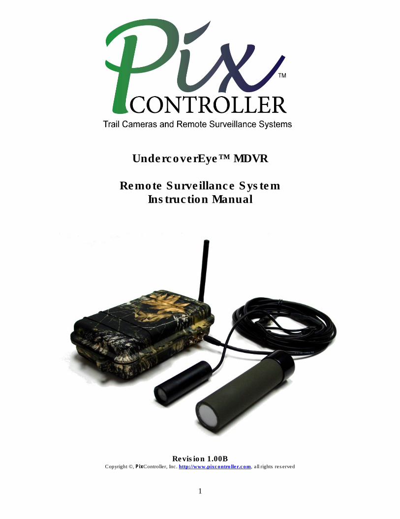
UndercoverEye™ MDVR
Remote Surveillance System Instruction Manual
Revision 1.00B Copyright ©, PixController, Inc. http://www.pixcontroller.com, all rights reserved
2
WARRANTY REGISTRATION PixController, Inc. warrants products sold by it and guarantees to correct, by repair or replacement at our option, any defects of material and workmanship which develop under normal and proper use within twelve (12) months from the date of the original purchase when inspection proves the fault to be of manufacturing. All such Products must be returned to our service center. This warranty does not apply to any of our Products which have been repaired or altered by unauthorized persons or service centers in any way so as, in our judgment, to injure their stability or reliability, or which have been subject to misuse, negligence, or accident or which have had their serial number altered, effaced or removed. We will not assume any expense or liability for repairs made by other parties without our written consent. PixController, Inc is not responsible for damage to any associated equipment or apparatus, nor shall we be held liable for loss of profit or other special damages. There is no other guarantee or warranty except as herein stated. Returns for any unaffected products are permitted within 14 days from the date of receipt of merchandise. After such time, items will incur a 15% restocking fee. Returns of wrong ordered items are allowed. Returned merchandise will be accepted only if all conditions are met. In no event shall PixController, Inc. be liable for any incidental, special, indirect or consequential damages, whether resulting from the use, misuse, or inability to use this product or from defects in this product. The Buyer is not permitted to tamper or remove any of the Raptor System electronics without voiding this warranty. The Buyer, his employees, or others assumes all risks and liabilities for the operation, the use and the misuse of the product described herein and agree to defend and to save the seller harmless from any and all claims arising from any cause whatsoever, including seller’s negligence for personal injury incurred in connection with the use of the said product. PixController, Inc reserves the right to discontinue models at any time or change specifications, price or design without notice and without incurring any obligation. The express warranties are in lieu of all other warranties, guarantees, promises, affirmations, or representations, express or implied which would be deemed applicable to the goods sold hereunder. No express warranties and no implied warranties, whether of merchantability, fitness for any particular use or purpose, against infringement, or otherwise (except as to title) other than those expressly set forth herein, shall apply.
FOR REPAIR CONTACT PixController, Inc. 1056 Corporate Lane Export, PA 15632 Phone: 724-733-0970 Fax: 724-733-0860 Email: [email protected] Web : http://www.pixcontroller.com
3
Table of Contents
1. What’s included with your UndercoverEye™ System 2. Inspection/Acceptance of received products
2.1 Contact Information 3. Introduction
4. UndercoverEye™ System Components 5. UndercoverEye DIP Switch Setting
5.1 DIP Switch Settings 5.2 Setting the Sensor Address Code 5.3 Event Delay Time 5.4 Setting Recording Length 5.5 Camera Mode 5.6 Power Device Mode
6. Setting up the UndercoverEye System 6.1 Installing System Components 6.2 Powering On the UndercoverEye System 6.3 Testing the UndercoverEye recording for the first time
7. Wireless RF Sensors
7.1 Wireless Sensor Introduction 7.2 Using the Wireless PIR Motion Sensor
8. UndercoverEye 12V LI-Ion Battery & Charger 9. Using Personal Video Players (PVP)
10. Playing the UndercoverEye MPEG4 Video Files
11. Video File Conversion Tools
12. Connecting Portable Monitors to the UndercoverEye System
13. DVR Remote Control
13.1 SET UP Menu 13.2 Image Setting Menu 13.3 REC. Setting Menu 13.4 REC. Mode Menu 13.5 Playback Menu 13.6 System Setting Menu
14. UndercoverEye Trigger Modes
15. External Charging Option
16. Using other cameras with your UndercoverEye
17. Connecting IR Illuminators
4
1. What’s included with your UndercoverEye™ System Your UndercoverEye™ system contains the following items:
• UndercoverEye™ water proof system case/motion control electronic
• Removable RF Antenna w/ SMA connector
• Bullet Video Camera • Video Cable
• Removable sound MIC/cable
• (1) Wireless PIR motion sensors • 12V 4.5AH Li-Ion rechargeable battery
• 12V battery charging unit
• 4GB Media Card
• DVR Remote Control • PixController UndercoverEye™ CD with manuals and media player
2. Inspection/Acceptance of received products The buyer shall be responsible for inspecting all products shipped prior to acceptance; provided, however, that if Buyer shall not have given PixController, Inc. written notice via email of rejection or shorted items to [email protected] within ten (10) days following receipt by Buyer, the products shall be deemed to have been accepted by Buyer. All electronic products sent back for a full refund are subject to a 15% restocking within thirty (30) days from purchase. Products authorized for return must be in their original unopened packaging to receive credit. Unauthorized returns will not be accepted. After thirty (30) days from purchase items may not be returned for a full refund. Your electronics are covered for a full 12 month period coving all part failure under normal use. 2.1 Contact Information Address: PixController, Inc. 1056 Corporate Lane Murry Corporate Park Export, PA 15632 Phone: 724-733-0970 FAX: 724-733-0860 Email: [email protected] Web: http://www.pixcontroller.com
5
3. Introduction The PixController UndercoverEye™ is a complete all-in-one covert remote video surveillance recording system. Video recordings are saved on standard SD memory cards in a MPEG4 video recording format. Capture more than 1 hour of footage at 640 X 480 @ 30 Frames per second in high resolution with sound per 1GB on a memory card. The UndercoverEye™ system box can be buried into the ground for the ultimate covert setup. Standard 12V analog cameras attach to the recording box via a 15’ cable. One very unique feature of the UndercoverEye system is that it can be triggered by wireless motion sensors or by camera pixel motion detection. Both of these triggering modes have their advantages and specific applications depending on how the system is deployed. This will be covered in greater detail in this manual. Sound can also be recorded with your UndercoverEye™ which is a very important feature. However, in situations where sound recording is not permitted you can simply unplug the sound MIC cable from the UndercoverEye™ unit. Being that there are no mechanical parts for running camcorder tape recording the UndercoverEye™ can be used in much lower temperature conditions where a camcorder will often freeze, and it can be used in much more humid weather conditions where a camcorder can be damaged by moisture, and will power up much faster than camcorders will. The DVR and Video Camera are powered by a rechargeable 12V SLA 3.4 AH battery, which under normal use can last from weeks to months of unattended use depending on the number of activations and trigger mode. The UndercoverEye™ can use multiple wireless PIR motion sensors which can cover a wide sensing area. If you are recording a trail area for example simply place one PIR sensor up the trail and one down the trail, and one in the center where UndercoverEye’s video camera is placed. In this scenario you can pre-trigger the UndercoverEye’s recording system before the subject walks into the video camera range.. The MPEG-4 files produced by the DVR can be played back directly on virtually any portable device accepting CF memory cards. You can also use it to view recorded video on your TV. Just plug it into the Video-In jacks on the TV and hit ‘Play’. And with your PVP USB connection or an inexpensive USB adaptor/Card reader (not included), you can easily drag and drop content from the memory card onto your computer to play it on your laptop or PC.
6
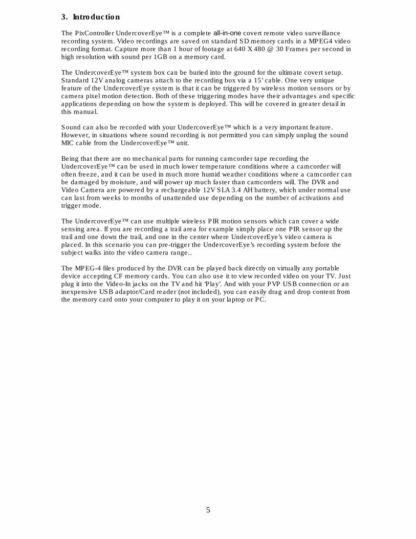
4. UndercoverEye™ System Components
UndercoverEye™ Exterior Components
UndercoverEye™ Interior Components
7
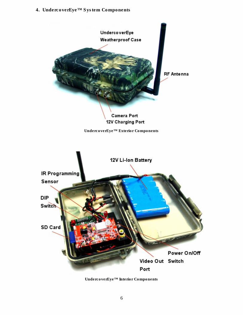
Video Cable Connections
Video Cable Connectors
8
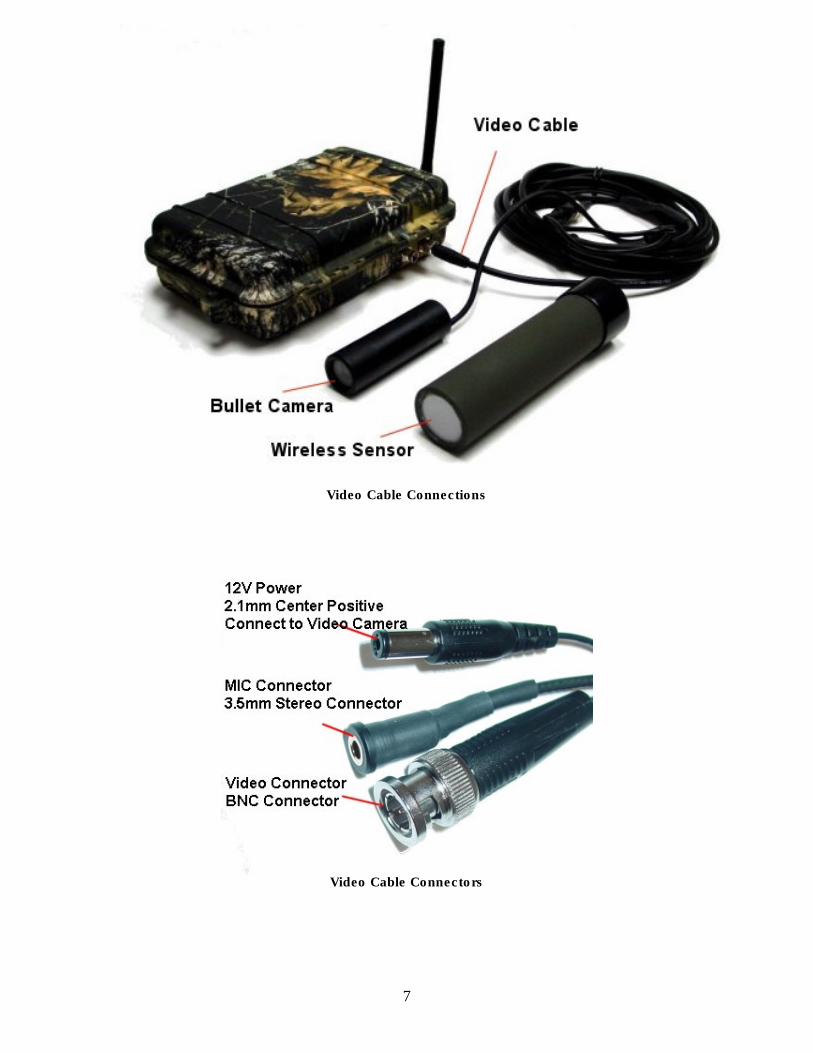
5. UndercoverEye DIP Switch Setting
Note: Orientation of DIP switch is upside down The DIP Controller Switch will let you customize how the operation of the UndercoverEye recording system. Here you can adjust the time delay between trigger events, set how long the DVR will record, adjust sensor addresses, and mode of operation. The User DIP switch is location on the top panel of the UndercoverEye control electronics. You will need a small flat blade screw driver to change the switch settings. Note, you must power the system off when changing DIP switch settings.
9
5.1 DIP Switch Settings Sensor Address Switch 1
Sensor “A” Off Sensor “B” On
Event Delay Time Switch 2 Switch 3
No Delay Off Off 30 Seconds On Off 1 Minute Off On 5 Minutes On On
Recording Time Switch 4 Switch 5
30 Sec./Cont. Off Off 1 Minute On Off 5 Minutes Off On 10 Minutes On On
Camera Mode Switch 6 Switch 7
24-hour Off Off Night Only On Off Day Only Off On Walk-Test On On Power Device Switch 8
Power Off” Off Power On” On
5.2 Setting the Sensor Address Code Switch 1 controls the address code of the UndercoverEye™ controller box. Both the Wireless Sensor, and UndercoverEye™ controller box need to be set to the same address code in order for the unit to function properly. The UndercoverEye™ is compatible with the 315MHz Wireless Sensor products from PixController, Inc. The UndercoverEye MDVR unit will respond to only address settings of A and B from the wireless sensor. Why set different address codes? There may be a situation when you want to have several UndercoverEye™ units in a recording session. You may want to only have several UndercoverEye ™ units respond to certain wireless sensors. For this you have the ability to set the address between each of these devices. It is a good idea to use a marking pen and write the address code on wireless sensor if not set in the default “A” address code
10
5.3 Event Delay Time Switches 2 and 3 control the delays between video shots. In some cases you might want to limit the amount of video taken in high traffic areas. 5.4 Setting Recording Length Switches 4 and 5 control Daylight, Night Time, and 24 Hour recording, and Test Mode 5.5 Camera Mode Switches 6 and 7 control the camera mode, which is if the camera system will record 24-hours, day only, or night only or test mode. When Test Mode is set to “On” it will let you test out the “line of sight” distance between the triggering unit, i.e., the wireless sensor, and the UndercoverEye™ unit. This is useful to be sure the camcorder units can see commands from the triggering units. In this mode you will hear a “beep” from the UndercoverEye unit when triggered. The unit will not record in this mode. Note: To put the UndercoverEye back into “recording mode” when using Test Mode. 5.6 Power Device Mode Switch 8 controls powers up the video camera and UndercoverEye™ for reviewing video in the field with a hand held video monitor/TV video monitor, or making changes to the DVR settings with the DVR remote control. In this mode the system can be setup for pixel motion detection. Note 1: To put the UndercoverEye back into “recording mode” when using Power Device Mode. If Switch 8 is up the system can’t be trigged to record events to the DVR by an external sensor. Note 2: When changing switch setting you must re-boot your UndercoverEye.
11
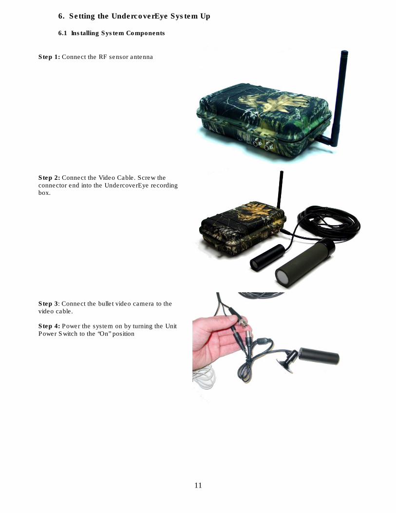
6. Setting the UndercoverEye System Up 6.1 Installing System Components
Step 1: Connect the RF sensor antenna
Step 2: Connect the Video Cable. Screw the connector end into the UndercoverEye recording box.
Step 3: Connect the bullet video camera to the video cable. Step 4: Power the system on by turning the Unit Power Switch to the “On” position
12
6.2 Powering On the UndercoverEye System
To power up the system turn the Power on/off switch to the "on" position. You will hear a short melody from the electronics letting you know it's powered on. Next there will be a 30 second delay. After this time expires you will hear 4 quick beeps which let you know the system is going into a 1 minute auto walk test phase. If you walk past the Wireless PIR motion sensors at this point you will hear 1 beep for a "A" Sensor or trigger sensor, and 2 beeps for a "B" sensor or power up sensor. You may want to keep the case open so you can hear this from a distance. After this 1 minute walk test phase expires you will hear 4 quick beeps again letting you know the system is going "active". After this point the system is active. 6.3 Testing the UndercoverEye Recording for the first time We suggest testing the unit in an office to become familiar how the system operates before deploying the unit in the field. First, set the DVR User DIP switches to the default position, which is all down and be sure the camera and DVR are installed properly (see above). Next, power the unit on and let the system go through the 1 ½ minute warm up and walk test phase. We suggest giving the unit about 2 minutes before triggering the system with the wireless sensor. We recommend connecting a TV monitor to the video output connector of the UndercoverEye system. When triggered you will see a recording symbol on the monitor. The system will record for 30 seconds. After the 30 second time expires the system will turn off. Power down the system when the DVR has finished recording, Pull the memory card from the DVR unit and place the memory card into your PC to view the MPEG4 video file.
13
7. Wireless RF Sensors
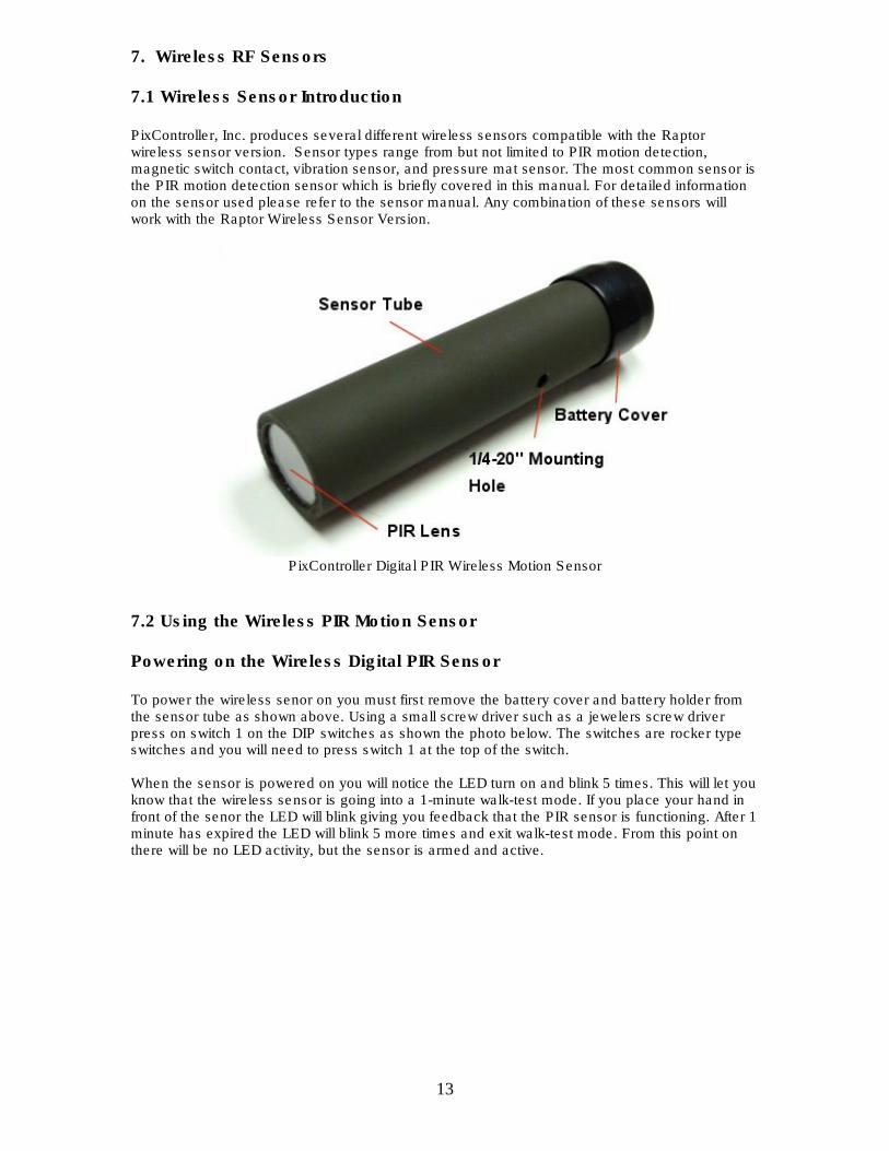
7.1 Wireless Sensor Introduction PixController, Inc. produces several different wireless sensors compatible with the Raptor wireless sensor version. Sensor types range from but not limited to PIR motion detection, magnetic switch contact, vibration sensor, and pressure mat sensor. The most common sensor is the PIR motion detection sensor which is briefly covered in this manual. For detailed information on the sensor used please refer to the sensor manual. Any combination of these sensors will work with the Raptor Wireless Sensor Version.
PixController Digital PIR Wireless Motion Sensor
7.2 Using the Wireless PIR Motion Sensor Powering on the Wireless Digital PIR Sensor To power the wireless senor on you must first remove the battery cover and battery holder from the sensor tube as shown above. Using a small screw driver such as a jewelers screw driver press on switch 1 on the DIP switches as shown the photo below. The switches are rocker type switches and you will need to press switch 1 at the top of the switch. When the sensor is powered on you will notice the LED turn on and blink 5 times. This will let you know that the wireless sensor is going into a 1-minute walk-test mode. If you place your hand in front of the senor the LED will blink giving you feedback that the PIR sensor is functioning. After 1 minute has expired the LED will blink 5 more times and exit walk-test mode. From this point on there will be no LED activity, but the sensor is armed and active.
14
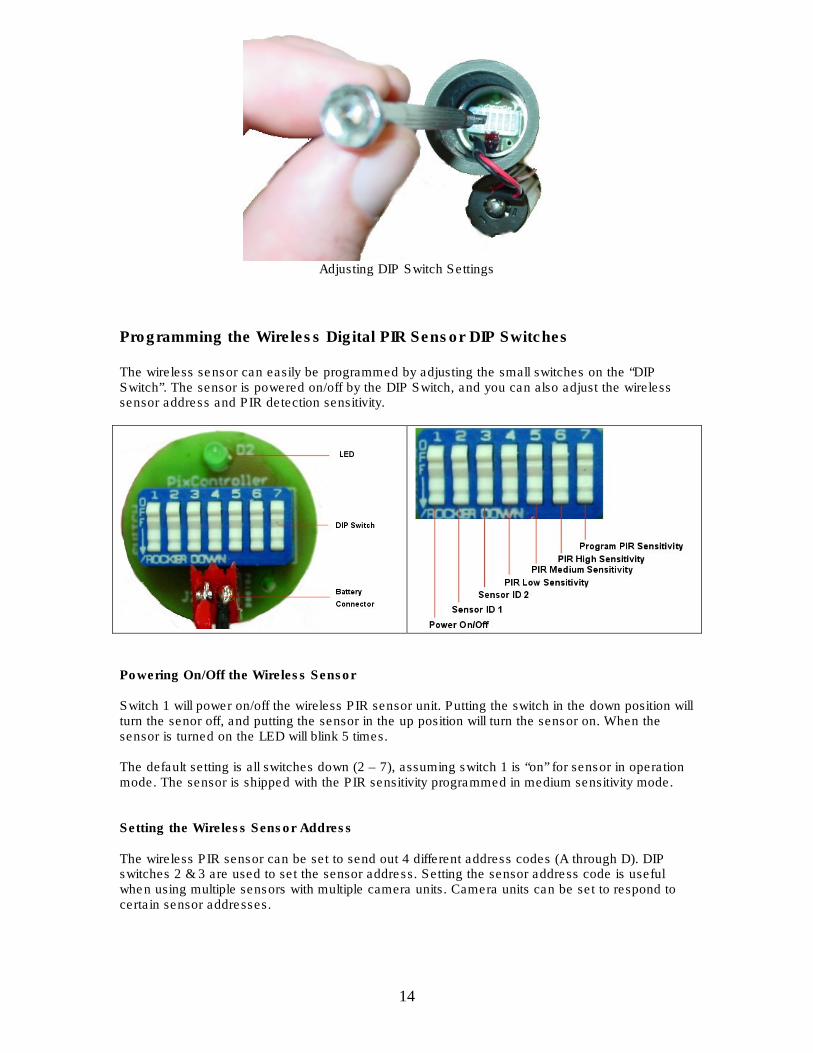
Adjusting DIP Switch Settings
Programming the Wireless Digital PIR Sensor DIP Switches
The wireless sensor can easily be programmed by adjusting the small switches on the “DIP Switch”. The sensor is powered on/off by the DIP Switch, and you can also adjust the wireless sensor address and PIR detection sensitivity.
Powering On/Off the Wireless Sensor Switch 1 will power on/off the wireless PIR sensor unit. Putting the switch in the down position will turn the senor off, and putting the sensor in the up position will turn the sensor on. When the sensor is turned on the LED will blink 5 times. The default setting is all switches down (2 – 7), assuming switch 1 is “on” for sensor in operation mode. The sensor is shipped with the PIR sensitivity programmed in medium sensitivity mode. Setting the Wireless Sensor Address The wireless PIR sensor can be set to send out 4 different address codes (A through D). DIP switches 2 & 3 are used to set the sensor address. Setting the sensor address code is useful when using multiple sensors with multiple camera units. Camera units can be set to respond to certain sensor addresses.
15
Sensor Address Switch 2 Switch 3 ---------------------------------------------------------- Address A Down Down Address B Down Up Address C Up Down Address D Up Up Note: When changing the sensor address you will need to power the sensor off and back on to take effect.
Setting Range-Test Mode Range-Test mode puts the sensor into a mode where it will send out trigger commands on 2-second intervals. In this mode the PIR sensor is inactive. This mode is used to set the range between the wireless PIR sensor and the receiving unit. To set Range-Test mode start with the wireless sensor in the power down state. Turn DIP switches 2 and 3 into the down “off” position. Next, power the sensor on by turning switch 1 into up “on” position. Wait for the LED to blink 5 times. Next, move switches 2 and 3 into the up “on” position. The wireless sensor is now in Range-Test mode. To take the wireless sensor out of Range-Test mode power the sensor down by turning switch 1 into the “off” position then turning switch 2 and 3 into the “off” position. Adjusting the Digital PIR Sensitivity DIP switches 4 – 7 are used to adjust the PIR sensitivity. The DIP switch functions are as follows: Switch 4 – Setting Low PIR Detection Sensitivity Switch 5 – Setting Medium PIR Detection Sensitivity Switch 6 – Setting High PIR Detection Sensitivity Switch 7 – Programming PIR Detection Sensitivity To adjust the PIR detection sensitivity be sure that the sensor is powered on. Next, select the desired sensitivity setting, low, medium, or high from switch settings 4 – 6. Turn that switch to the “on” position, then turn switch 7 to the “on” position for at least 1 second. Lastly, turn both switches “off”. The programming is now complete. Note, programming the sensitivity can be done at time the unit is powered on. Sensitivity adjustments may be necessary when using the wireless PIR sensor in hot climates. Typically you want to use a lower PIR sensitivity setting under very hot conditions. Under cooler conditions the PIR sensitivity can be increased for longer detection ranges. Note: It is always a good idea to place the wireless sensor under a covered area to keep the sensor cool. Avoid placing the sensor on small trees which can blow around in the wind and cause false triggers. Also, trim away any brush directly in front of the PIR lens which can cause false triggers if they are heated by the sun and start moving.
16
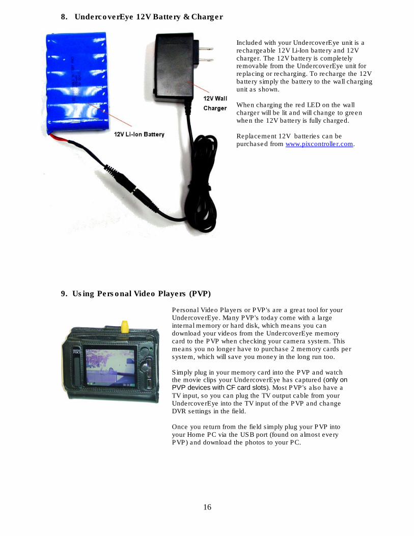
8. UndercoverEye 12V Battery & Charger
Included with your UndercoverEye unit is a rechargeable 12V Li-Ion battery and 12V charger. The 12V battery is completely removable from the UndercoverEye unit for replacing or recharging. To recharge the 12V battery simply the battery to the wall charging unit as shown. When charging the red LED on the wall charger will be lit and will change to green when the 12V battery is fully charged. Replacement 12V batteries can be purchased from www.pixcontroller.com.
9. Using Personal Video Players (PVP)
Personal Video Players or PVP's are a great tool for your UndercoverEye. Many PVP's today come with a large internal memory or hard disk, which means you can download your videos from the UndercoverEye memory card to the PVP when checking your camera system. This means you no longer have to purchase 2 memory cards per system, which will save you money in the long run too. Simply plug in your memory card into the PVP and watch the movie clips your UndercoverEye has captured (only on PVP devices with CF card slots). Most PVP's also have a TV input, so you can plug the TV output cable from your UndercoverEye into the TV input of the PVP and change DVR settings in the field. Once you return from the field simply plug your PVP into your Home PC via the USB port (found on almost every PVP) and download the photos to your PC.
17
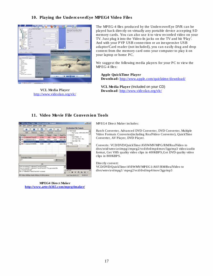
10. Playing the UndercoverEye MPEG4 Video Files
VCL Media Player http://www.videolan.org/vlc/
The MPEG-4 files produced by the UndercoverEye DVR can be played back directly on virtually any portable device accepting SD memory cards. You can also use it to view recorded video on your TV. Just plug it into the Video-In jacks on the TV and hit ‘Play’. And with your PVP USB connection or an inexpensive USB adaptor/Card reader (not included), you can easily drag and drop content from the memory card onto your computer to play it on your laptop or home PC. We suggest the following media players for your PC to view the MPEG-4 files: Apple QuickTime Player Download: http://www.apple.com/quicktime/download/ VCL Media Player (Included on your CD) Download: http://www.videolan.org/vlc/
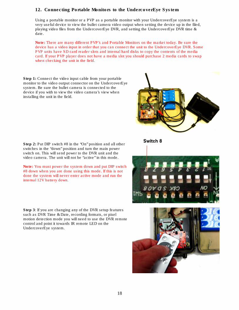
11. Video Movie File Conversion Tools
MPEG4 Direct Maker http://www.artech365.com/mpeg4maker/
MPEG4 Direct Maker includes: Batch Converter, Advanced DVD Converter, DVD Converter, Multiple Video Formats Converter(including RealVideo Converter), QuickTime Converter, AV Player, DVD Player. Converts: VCD/DVD/QuickTime/AVI/WMV/MPG/RM/RealVideo to divx/xvid/wmv/avi/mpg1/mpeg2/vcd/dvd/mp4/mov/3gp/mp3 video/audio format, Get VHS quality video clips in 400KBPS,Get DVD quality video clips in 800KBPS. Directly convert: VCD/DVD/QuickTime/AVI/WMV/MPEG1/ASF/RM/RealVideo to divx/wmv/avi/mpg1/ mpeg2/vcd/dvd/mp4/mov/3gp/mp3
18
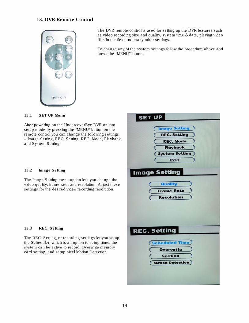
12. Connecting Portable Monitors to the UndercoverEye System Using a portable monitor or a PVP as a portable monitor with your UndercoverEye system is a very useful device to view the bullet camera video output when setting the device up in the filed, playing video files from the UndercoverEye DVR, and setting the UndercoverEye DVR time & date. Note: There are many different PVP’s and Portable Monitors on the market today. Be sure the device has a video input in order that you can connect the unit to the UndercoverEye DVR. Some PVP units have SD card reader slots and internal hard disks to copy the contents of the media card. If your PVP player does not have a media slot you should purchase 2 media cards to swap when checking the unit in the field.
Step 1: Connect the video input cable from your portable monitor to the video output connector on the UndercoverEye system. Be sure the bullet camera is connected to the device if you with to view the video camera’s view when installing the unit in the field.
Step 2: Put DIP switch #8 in the “On” position and all other switches in the “down” position and turn the main power switch on. This will send power to the DVR unit and the video camera. The unit will not be “active” in this mode. Note: You must power the system down and put DIP switch #8 down when you are done using this mode. If this is not done the system will never enter active mode and run the internal 12V battery down.
Step 3: If you are changing any of the DVR setup features such as DVR Time & Date, recording formats, or pixel motion detection mode you will need to use the DVR remote control and point it towards IR remote LED on the UndercoverEye system.
19
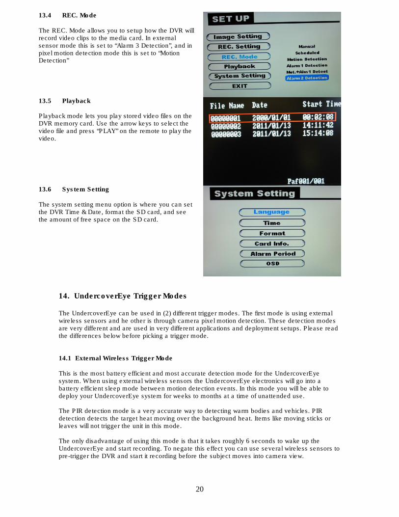
13. DVR Remote Control
The DVR remote control is used for setting up the DVR features such as video recording size and quality, system time & date, playing video files in the field and many other settings. To change any of the system settings follow the procedure above and press the “MENU” button.
13.1 SET UP Menu
After powering on the UndercoverEye DVR on into setup mode by pressing the “MENU” button on the remote control you can change the following settings – Image Setting, REC. Setting, REC. Mode, Playback, and System Setting.
13.2 Image Setting
The Image Setting menu option lets you change the video quality, frame rate, and resolution. Adjust these settings for the desired video recording resolution.
13.3 REC. Setting
The REC. Setting, or recording settings let you setup the Scheduler, which is an option to setup times the system can be active to record, Overwrite memory card setting, and setup pixel Motion Detection.
20
13.4 REC. Mode
The REC. Mode allows you to setup how the DVR will record video clips to the media card. In external sensor mode this is set to “Alarm 3 Detection”, and in pixel motion detection mode this is set to “Motion Detection”
13.5 Playback
Playback mode lets you play stored video files on the DVR memory card. Use the arrow keys to select the video file and press “PLAY” on the remote to play the video.
13.6 System Setting
The system setting menu option is where you can set the DVR Time & Date, format the SD card, and see the amount of free space on the SD card.
14. UndercoverEye Trigger Modes The UndercoverEye can be used in (2) different trigger modes. The first mode is using external wireless sensors and he other is through camera pixel motion detection. These detection modes are very different and are used in very different applications and deployment setups. Please read the differences below before picking a trigger mode. 14.1 External Wireless Trigger Mode This is the most battery efficient and most accurate detection mode for the UndercoverEye system. When using external wireless sensors the UndercoverEye electronics will go into a battery efficient sleep mode between motion detection events. In this mode you will be able to deploy your UndercoverEye system for weeks to months at a time of unattended use. The PIR detection mode is a very accurate way to detecting warm bodies and vehicles. PIR detection detects the target heat moving over the background heat. Items like moving sticks or leaves will not trigger the unit in this mode. The only disadvantage of using this mode is that it takes roughly 6 seconds to wake up the UndercoverEye and start recording. To negate this effect you can use several wireless sensors to pre-trigger the DVR and start it recording before the subject moves into camera view.
21
14.2 Camera Pixel Motion Detection Trigger Mode When using camera pixel motion detection mode the UndercoverEye camera will “see” the motion and the wireless sensors will not be used. In this mode the camera and DVR are powered all the time, and this will draw a lot of current from the battery. This will drastically shorten the battery life to just several days of deployment. In pixel motion detection mode may objects such as sticks and leaves can trigger the system. Features such as motion detection areas and sensitivity can be setup in the motion detection menu. Other areas where this trigger mode can struggle are lighting. Low light is very hard for the DVR to detect motion in this mode. Typically this mode is used for indoor applications where the lighting and motion is more controlled, and you can externally charge the UndercoverEye system. The big advantage of this trigger mode is that there is no delay between when the trigger event takes place and when the DVR will start recording. There is also a pre-buffer mode which will record a few seconds before the trigger event occurs. Note: When using this mode we strongly recommend using the external charging cable option with a 12V power source. The 12V power source can be the AC Wall Charger or 12V battery such as a marine cell battery. 14.3 Setting Up Camera Pixel Motion Detection Mode
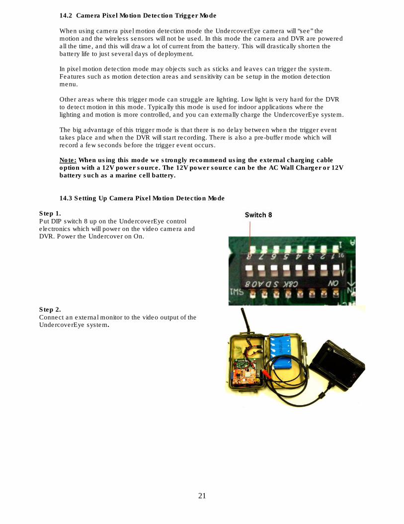
Step 1. Put DIP switch 8 up on the UndercoverEye control electronics which will power on the video camera and DVR. Power the Undercover on On.
Step 2. Connect an external monitor to the video output of the UndercoverEye system.
22
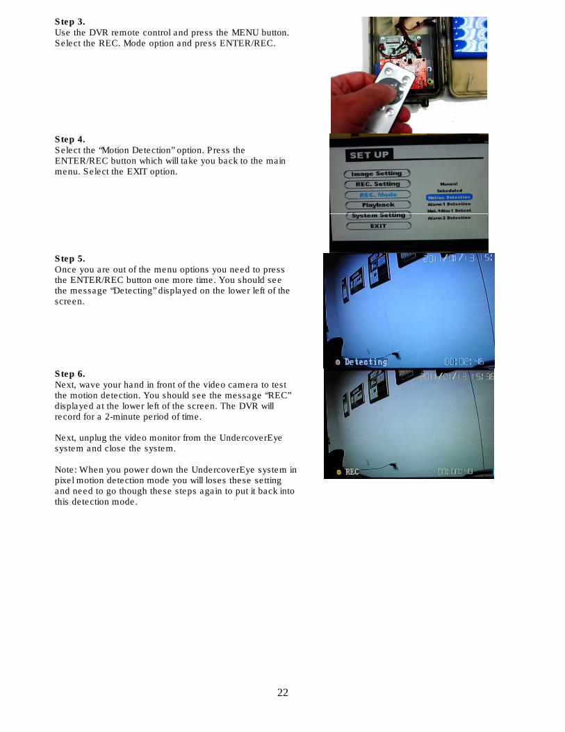
Step 3. Use the DVR remote control and press the MENU button. Select the REC. Mode option and press ENTER/REC.
Step 4. Select the “Motion Detection” option. Press the ENTER/REC button which will take you back to the main menu. Select the EXIT option.
Step 5. Once you are out of the menu options you need to press the ENTER/REC button one more time. You should see the message “Detecting” displayed on the lower left of the screen.
Step 6. Next, wave your hand in front of the video camera to test the motion detection. You should see the message “REC” displayed at the lower left of the screen. The DVR will record for a 2-minute period of time. Next, unplug the video monitor from the UndercoverEye system and close the system. Note: When you power down the UndercoverEye system in pixel motion detection mode you will loses these setting and need to go though these steps again to put it back into this detection mode.
23
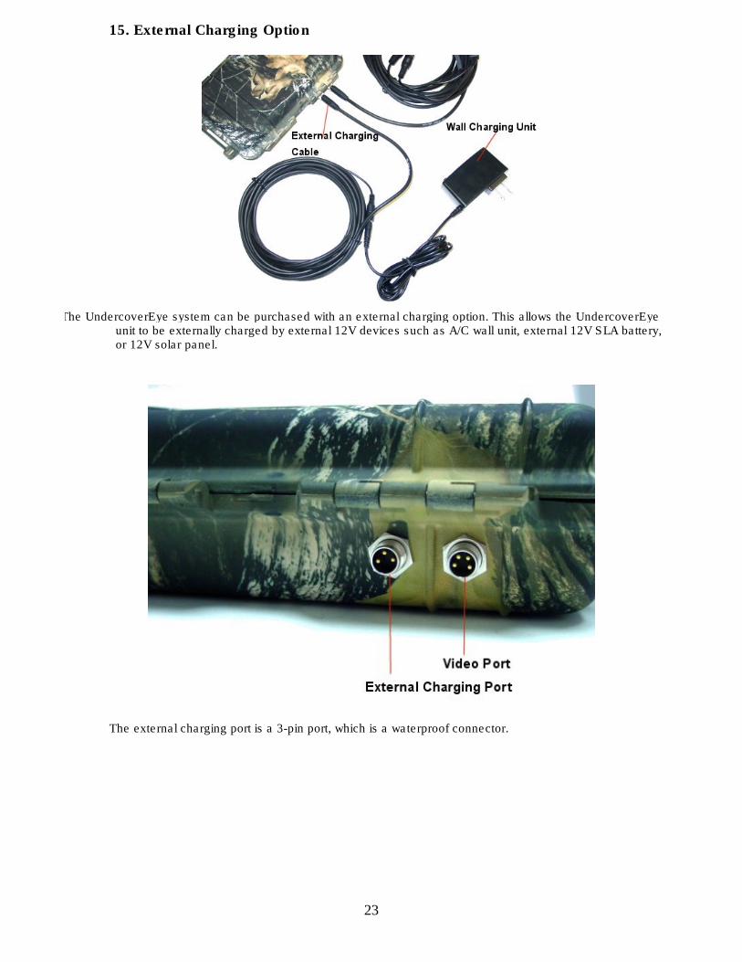
15. External Charging Option
The UndercoverEye system can be purchased with an external charging option. This allows the UndercoverEye
unit to be externally charged by external 12V devices such as A/C wall unit, external 12V SLA battery, or 12V solar panel.
The external charging port is a 3-pin port, which is a waterproof connector.
24
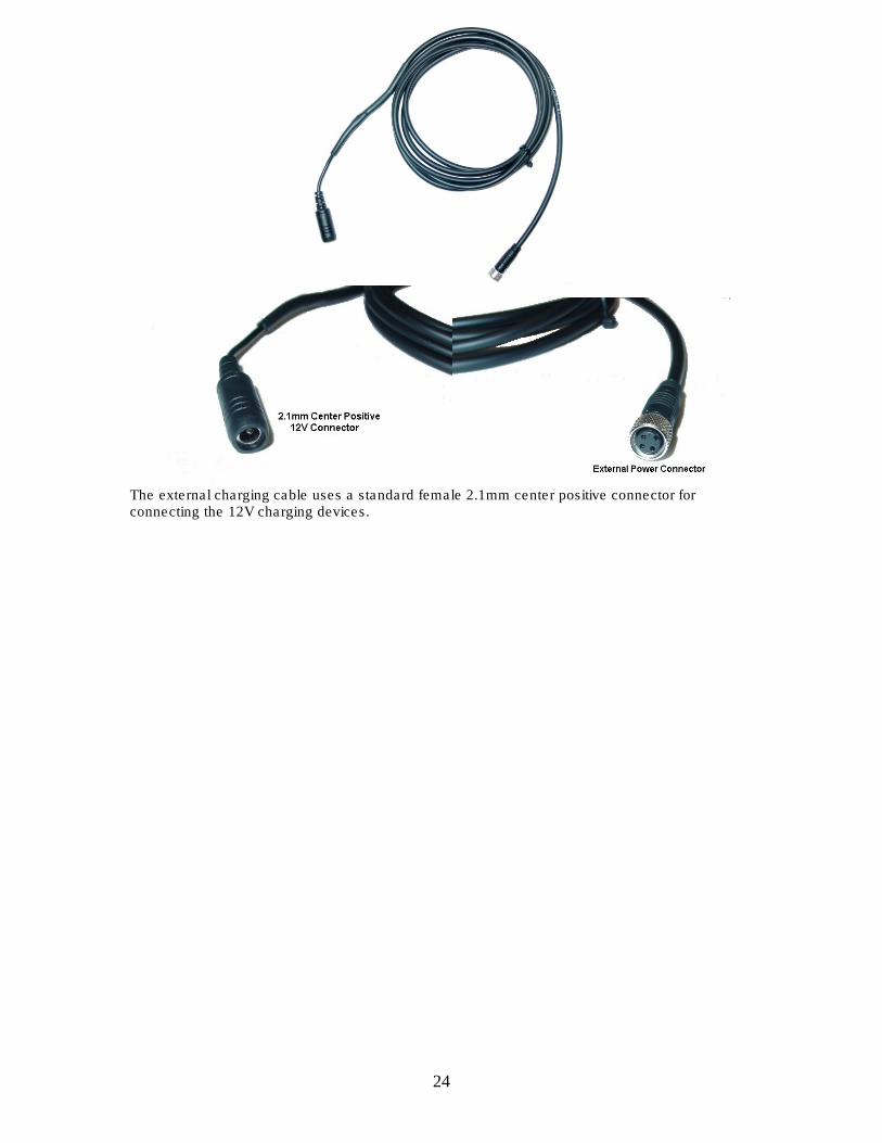
The external charging cable uses a standard female 2.1mm center positive connector for connecting the 12V charging devices.
25
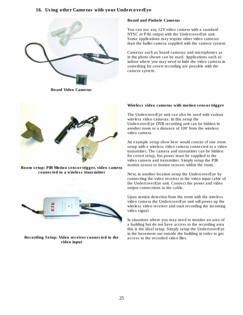
16. Using other Cameras with your UndercoverEye
Board Video Cameras
Board and Pinhole Cameras You can use any 12V video camera with a standard NTSC or PAL output with the UndercoverEye unit. Some applications may require other video cameras than the bullet camera supplied with the camera system Cameras such as board cameras and microphones as in the photo shown can be used. Applications such as indoor where you may need to hide the video camera in something for covert recording are possible with the camera system.
Room setup: PIR Motion sensor trigger, video camera
connected to a wireless transmitter
Recording Setup: Video receiver connected to the
video input
Wireless video cameras with motion sensor trigger The UndercoverEye unit can also be used with various wireless video cameras. In this setup the UndercoverEye DVR recording unit can be hidden in another room or a distance of 100’ from the wireless video camera. An example setup show here would consist of one room setup with a wireless video camera connected to a video transmitter. The camera and transmitter can be hidden for covert setup, but power must be supplied to the video camera and transmitter. Simply setup the PIR motion sensor or motion sensors within the room. Next, in another location setup the UndercoverEye by connecting the video receiver to the video input cable of the UndercoverEye unit. Connect the power and video output connections to the cable. Upon motion detection from the room with the wireless video camera the UndercoverEye unit will power up the wireless video receiver and start recording the incoming video signal. In situations where you may need to monitor an area of a building but do not have access to the recording area this is the ideal setup. Simply setup the UndercoverEye in the basement our outside the building in order to get access to the recorded video files.
26
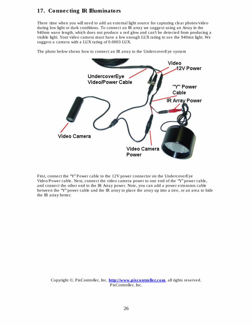
17. Connecting IR Illuminators There time when you will need to add an external light source for capturing clear photos/video during low light or dark conditions. To connect an IR array we suggest using an Array in the 940nm wave length, which does not produce a red glow and can’t be detected from producing a visible light. Your video camera must have a low enough LUX rating to see the 940mn light. We suggest a camera with a LUX rating of 0.0003 LUX. The photo below shows how to connect an IR array to the UndercoverEye system
First, connect the “Y” Power cable to the 12V power connector on the UndercoverEye Video/Power cable. Next, connect the video camera power to one end of the “Y” power cable, and connect the other end to the IR Array power. Note, you can add a power extension cable between the “Y” power cable and the IR array to place the array up into a tree, or an area to hide the IR array better.
Copyright ©, PixController, Inc. http://www.pixcontroller.com, all rights reserved. PixController, Inc.