mdvr manual (application) - gbeshop.com · mdvr manual (application) 2 ... to start manual...
TRANSCRIPT

MDVR Manual
(Application)
2
Directory
1 Frontpanel and backpanel and MDVR installation instructions ..................................................... 3
1.1 Description of front panel ................................................................................................... 3
1.2 Backpanel interface specification ............................................................................. 4
1.3 wiring instructions .................................................................................................... 5
1.3.1 the AV video and audio input line shows ................................................ 5
1.3.2 Power cord Description ................................................................................. 5
1.3.3 I / O alarm input and output instructions ............................................. 6
1.4 MDVR check ........................................................................................................................ 6
1 4.1 Open boxes and accessories checks ................................................................... 6
1 4.2 SD card installation instructions ........................................................................ 7
2 remote control instructions ........................................................................................................... 8
3 MDVR operating instructions ....................................................................................................... 10
3.1 the preview interface .............................................................................................. 11
3.2 video retrieval .......................................................................................................... 11
3.3 video playback instructions .................................................................................. 13
4 3G network & platform using ....................................................................................................... 13
4.1 3G network instrictions ..................................................................................................... 13
4.2 3G platform using instruction ............................................................................... 15
4.3 3G Checking ....................................................................................................................... 17
3
1 Front panel/ Back panel and MDVR
installation instructions
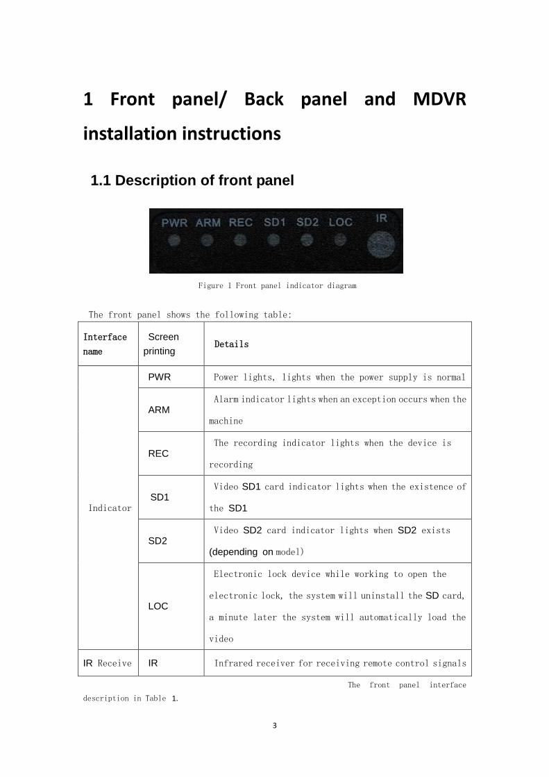
1.1 Description of front panel
Figure 1 Front panel indicator diagram
The front panel shows the following table:
Interface
name
Screen
printing Details
Indicator
PWR Power lights, lights when the power supply is normal
ARM Alarm indicator lights when an exception occurs when the
machine
REC The recording indicator lights when the device is
recording
SD1 Video SD1 card indicator lights when the existence of
the SD1
SD2 Video SD2 card indicator lights when SD2 exists
(depending on model)
LOC
Electronic lock device while working to open the
electronic lock, the system will uninstall the SD card,
a minute later the system will automatically load the
video
IR Receive IR Infrared receiver for receiving remote control signals
The front panel interface
description in Table 1.

4
1.2 Back panel interface specification
Figure 2 Panel interface diagram
Back panel connectors are described below the table:
Interface
name
Machine screen
printing
Details
Power
Interface
POWER The power input interface, which can be accessed
DC8-36V
Printer
port
MCU Debugging information interface
I / O alarm
Interface
I / O Enter the vehicle speed pulse signal, the
differential input
RS232 and RS485 serial data communication
interface
Alarm Interface, 12V and 5V power output
interface
Video and
audio input
interface
AV1, AV2, AV3,
AV4
A pin is the positive power supply (+12 V), 2 feet
of ground (GND), 3-foot audio input, 4 feet for the
video input
Video
output Video Out
Video analog output interface, access CVBS TV
and other display devices
Audio Audio Out Audio output
5
output
Table 2 Panel Interface
Description
1.3 wiring instructions
1.3.1 AV video and audio input line shows
Figure 3 AV cable access diagram
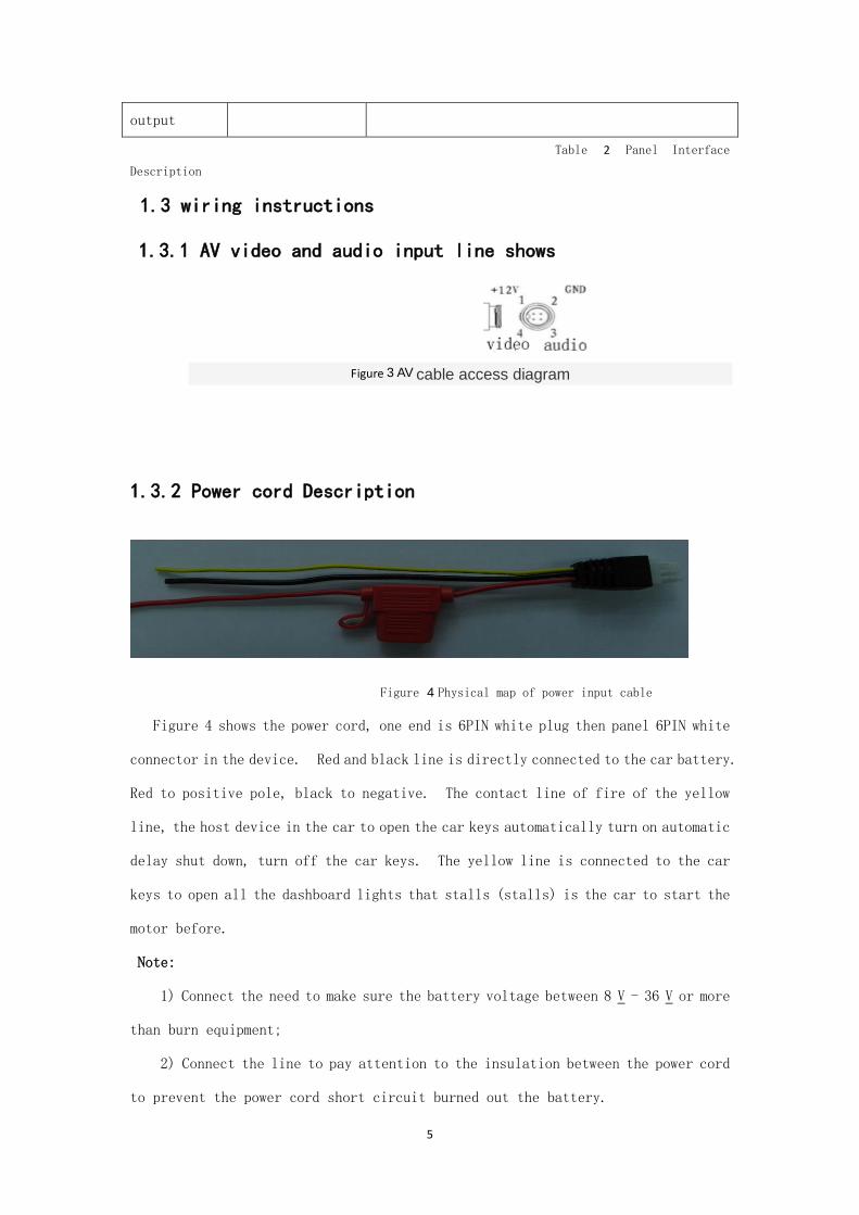
1.3.2 Power cord Description
Figure 4 Physical map of power input cable
Figure 4 shows the power cord, one end is 6PIN white plug then panel 6PIN white
connector in the device. Red and black line is directly connected to the car battery.
Red to positive pole, black to negative. The contact line of fire of the yellow
line, the host device in the car to open the car keys automatically turn on automatic
delay shut down, turn off the car keys. The yellow line is connected to the car
keys to open all the dashboard lights that stalls (stalls) is the car to start the
motor before.
Note:
1) Connect the need to make sure the battery voltage between 8 V - 36 V or more
than burn equipment;
2) Connect the line to pay attention to the insulation between the power cord
to prevent the power cord short circuit burned out the battery.

6
3) Yellow line must be connected to the firing line, otherwise the device will
not support the delayed shutdown, the final video will be lost.
4) Note: The car installation must have direct access from the battery positive
and negative, can not do with car Ground which will produce negative pulses
interfere with the normal operation of the host. Positive and negative power
wire size must be a Φ of 1.5 mm or more.
1.3.3 I / O alarm input and output instructions
Figure 5 Alarm Interface Definition
The device has 4 alarm input interface, and two alarm output interface. Alarm input
detection level detection, can be accessed by a variety of vehicles driving status,
such as braking, steering, horn, etc.
Alarm outputs are power level output drive capability of 200mA, if you want to
drive power is relatively large devices, must be an external relay.
1.4 MDVR check
1 4.1 Open boxes and accessories checks
Out of the box, check the host whether deformation or other damage to the nature
of the subject to please stop using and to get in touch with your supplier.

7
Table 3 Packing List
Figure 6 Annex physical map
The definition of video and audio cable: red line for the 12V positive, black wire
is ground negative, yellow line audio cable video cable, the Green Line
1 4.2 SD card installation instructions
SD card on the motherboard from the host front-end can be inserted into the SD
card. SD card at the SD card port and press in place (when you insert the SD
card to pay attention to positive and negative, negative downward).
8
2 remote control instructions
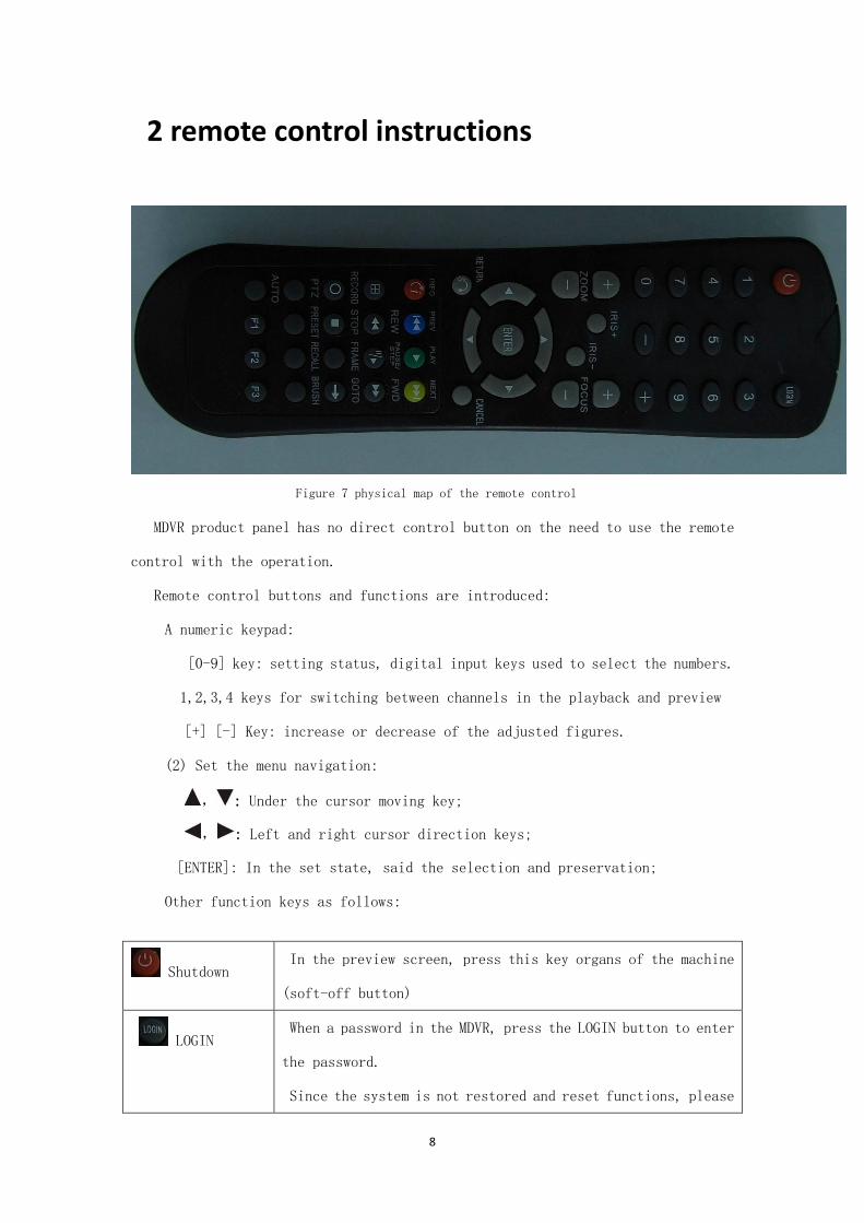
Figure 7 physical map of the remote control
MDVR product panel has no direct control button on the need to use the remote
control with the operation.
Remote control buttons and functions are introduced:
A numeric keypad:
[0-9] key: setting status, digital input keys used to select the numbers.
1,2,3,4 keys for switching between channels in the playback and preview
[+] [-] Key: increase or decrease of the adjusted figures.
(2) Set the menu navigation:
, : Under the cursor moving key;
, : Left and right cursor direction keys;
[ENTER]: In the set state, said the selection and preservation;
Other function keys as follows:
Shutdown In the preview screen, press this key organs of the machine
(soft-off button)
LOGIN When a password in the MDVR, press the LOGIN button to enter
the password.
Since the system is not restored and reset functions, please

9
remember the password;
Not provided with a password, press LOGN can visit the main
page;
INFO Information view, press to quickly view the configuration
information such as GPS, 3G and other modules;
Swastika key
The number keys 1,
2, 3, 4
Press the key to display the four screen on the monitor screen
is used to switch between the four-screen and single screen;;
press the number keys 1, 2, 3 and 4, respectively, to switch
to a single screen CH1, CH2, CH3, CH4,
RTURN /
CANCEL
Return to the previous layer of sub-menu. Eventually exit the
setup menu and exit to the monitor screen;
PAUSE / the
STEP
Suspend play and put the key frame (frame put: a single picture
playback, a picture according to time playback), press the play
like the key to return to normal playback speed playback of
video data;
GOTO Jump to a specified point in time in the playback of the video
to start playing
PLAY To start playback (screen paused still picture);
FWD Playback video files fast forward button, a fourth gear: 2X,
4X, 8X, 16X
REW Playback of image files and rewind buttons, a fourth gear: 2X,
4X, 8X, 16X
STOP Stop the manual recording button
RECORD To start manual recording button.
NEXT In the playback of video files slow release button, a third
gear: 1/2, 1/4, 1/8;

10
AUTO, PRESET,
RECALL, ZOOM +,
ZOOM-, FOCUS +,
FOCUS-, the IRIS,
the IRIS-PTZ,
BRUSH
PTZ function key
F1, F2, F3, Spare key, customers can be customized features
Table 4 Description of remote controller keys
3 MDVR operating instructions
Figure 8 main menu
Each menu item corresponds to the function defined as follows:
<Video search>: search the hard disk / video files stored in
SD card and playback operation;
<Video>: audio and video parameters, set the video mode;
<Feature set>: Set the alarm, PTZ, time, network;

11
<System Information>: Displays the serial number, version
number, MAC address, and other system information;
<Vehicle>: set the vehicle license plate number, timer switch,
WIFI;
<Display Settings>: Set the monitor screen and the content of
the video data, including the display of information, regional,
color, volume, etc.;
<Password management>: Set the machine password;
<Exit>: exit the menu interface, returns to direct the
monitoring interface.
3.1 Preview Interface
Figure 9 through the monitor screen card video card prompts Figure
Straight through the preview screen will display the message of the state of
equipment and each channel state, the meaning of the message is as follows:
[2011-8 - 31 09:54:34] shows the system time
[CHx] channel name
[● REC】 Said video recording is in progress
NO DISK], that there is no recording video
[The GPS: NO ...] when you press the remote control "INFO" key quickly to display
system information, such as GPS and other state
3.2 Video retrieval
12
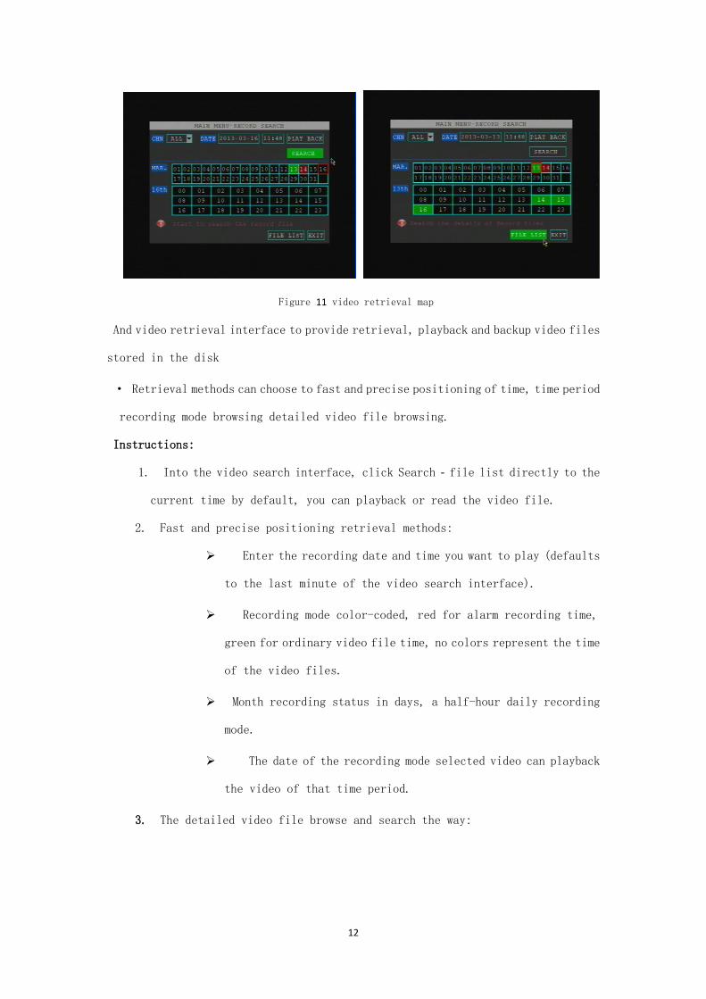
Figure 11 video retrieval map
And video retrieval interface to provide retrieval, playback and backup video files
stored in the disk
· Retrieval methods can choose to fast and precise positioning of time, time period
recording mode browsing detailed video file browsing.
Instructions:
1. Into the video search interface, click Search - file list directly to the
current time by default, you can playback or read the video file.
2. Fast and precise positioning retrieval methods:
Enter the recording date and time you want to play (defaults
to the last minute of the video search interface).
Recording mode color-coded, red for alarm recording time,
green for ordinary video file time, no colors represent the time
of the video files.
Month recording status in days, a half-hour daily recording
mode.
The date of the recording mode selected video can playback
the video of that time period.
3. The detailed video file browse and search the way:

13
If the retrieved time video, then click File> button, to open
more file browser interface, the list shows selected date video
files, you can flip.
Display content, including video files, start time, end time,
file size, video type.
Screening by record type file.
You can select the video file, and select the video files
are backed up.
3.3 video playback instructions
A single-channel playback and multi-channel synchronous playback in two ways.
2 player mode control, including:
Select normal playback, single frame playback, slow motion, fast
forward and rewind.
Adjust the volume.
(1) Fast forward: 2X (2x)-16X (16x)
(2) Rewind: 2X (1 minutes back)-16X (Back 8 minutes)
(3) jump (GOTO): pop-up input box to display the change to play the beginning
of the file (start) to end (end) time scope, the time edit box is set to jump time
(must between start and end time), exit edit box, select OK.>, OK!
Such as:
Start: [02:00:00] end: [02:30:00]
Editor [02:18:00] to determine after the jump to the time to play
around [02:18:00]
4 3G network & platform using
4.1 3G Network Instruction
1)Confirming which Telecom operator you use ,China Telecom, China Unicom or China Telecom?
2)Inserting the 3G card (SIM card),make sure the 3G card balance)
3)Checking the 3G antenna is connected properly
4)The product’s setting which need reconfirming

14
Main Menu-Record Setting- Small stream configuration. The remote 3G watching ‘s channel code
need setting as open. The user could change different channels resolution (CIF or QCIF) and
frame rate based on different condition
Main Menu - Vehicle management- Wireless internet access function need to set as open
Main Menu - vehicle management - basic setting, need to confirm with the supplier whether the
vehicle number (such as 04017) assigns the correct
15
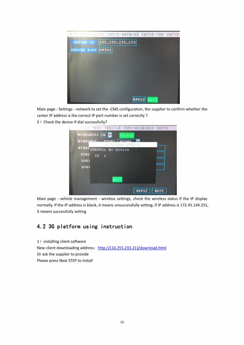
Main page - Settings - network to set the -CMS configuration, the supplier to confirm whether the
center IP address is the correct IP port number is set correctly ?
5)Check the device if dial successfully?
Main page - vehicle management - wireless settings, check the wireless status if the IP display
normally. If the IP address is blank, it means unsuccessfully setting; if IP address is 172.45.144.251,
it means successfully setting
4.2 3G platform using instruction
1)installing client software
New client downloading address:http://116.255.233.211/download.html
Or ask the supplier to provide
Please press Next STEP to install

16
2)Sign in
Ask the Supplier for administrator and pass word, the server and port
After a successful login, Double-click the device channel you will use
17
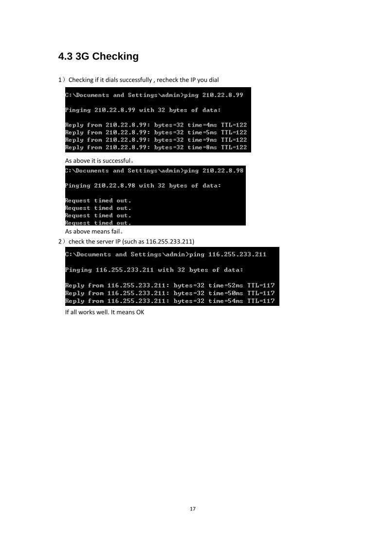
4.3 3G Checking
1)Checking if it dials successfully , recheck the IP you dial
As above it is successful。
As above means fail。
2)check the server IP (such as 116.255.233.211)
If all works well. It means OK