ultrawave bts installation and commissioning guide · pdf fileii ultrawave bts installation...
TRANSCRIPT

Part Number 680208-001/03 Version A
UltraWAVE BTS
Installation and CommissioningGuide
Release 6.5
ii UltraWAVE BTS Installation and Commissioning Guide, Release 6.5A
The products described in this document are products of interWAVE Communications, Inc. or its licensers. No part of this document may be photocopied, reproduced, translated, transferred, disclosed or otherwise provided to third parties without the prior written consent of an officer of interWAVE Communications, Inc.
This document applies to the interWAVE Communications, Inc. release of the GSM product line and to all subsequent versions and releases of the hardware or software unless otherwise indicated in a new version or an update package for this edition.
Publications requests should be addressed to your local sales support office.
interWAVE Communications, Inc. reserves the right to make changes to any products described herein at any time without notice. interWAVE Communications International, Ltd. and interWAVE Communications, Inc. do not assume any responsibility or liability arising out of the application or use of any product described herein, except as expressly agreed to in writing by interWAVE Communications, Inc. nor does the purchase or use of a product from interWAVE Communications, Inc. convey a license under any patent rights, copyrights, trademark rights, or any other of the intellectual property rights of interWAVE Communications International, Ltd. or third parties.
Use, duplication, or disclosure by the U.S. Government is subject to restrictions of FAR 52.227-14 (g) (2) (6/87) and FAR 52.227-19 (6/87), or DFAR 252.227-7015 (b) (6/95) and DFAR 227.7202-3 (a).
The software described in this document is furnished under a license agreement or nondisclosure agreement. The software may be used or copied only in accordance with the terms of the agreement. It is a violation of interWAVE Communications International, Ltd. proprietary rights to copy the software on any medium except as specifically allowed in the license or nondisclosure agreement. interWAVE's products are patented by one or more of the following United States Patents: No. 5,781,582, No. 5,682,403, No. 5,734,979, No. 5,734,699, No. 5,999,813, No. 5,953,651, No. 5,887,256, No. 5,577,029, No. 5,761,195, No. 5,842,138, No. 5,818,824, No. 5,957,464, No. 6,078,823, No. 6,070,071, No. 6,101,400, No. USP D 391,967, No. USP D 391,968, No. USP D 397,693.
Trademark Acknowledgment
interWAVE, WAVEXpress, MicroXpress, WAVEXchange, WAVEView, GSM Network in a Box, and TurboWAVE are trademarks or registered trademarks of interWAVE Communications International, Ltd. All other trademarks, service marks and product names mentioned in this document are the property of their respective owners.
©2003 interWAVE Communications, Inc. All Rights Reserved.
iii
United States Federal Communications Commission Required User Information
Located on the equipment is a label that contains, among other information, the FCC registration number. If requested, this information must be provided to the telephone company.
The UltraWAVE BTS Series AUAC series complies with Part 22 of the FCC Rules.
The 1900 MHz WAVEXpress Series M50 complies with Part 24 of the FCC Rules.
This equipment cannot be used on the telephone company-provided coin service. Connection to Party Line Service is subject to State Tariffs.
If this equipment causes harm to the telephone network, the telephone company will notify you in advance that temporary discontinuance of service may be required. If advance notice isn’t practical, the telephone company will notify the customer as soon as possible. Also, you will be advised of your right to file a complaint with the FCC if you believe it is necessary.
The telephone company may make changes in its facilities, equipment, operations, of procedures that could affect the operation of the equipment. If this happens, the telephone company will provide advance notice in order for you to make the necessary modifications in order to maintain uninterrupted service.
If trouble is experienced with this equipment, please contact:
interWAVE Communications, Inc. 312 Constitution Drive Menlo Park, CA 94025 Phone: 650.838.2117
If the trouble is causing harm to the telephone network, the telephone company may request you to remove the equipment from the network until the problem is resolved.
It is recommended that the customer install an AC surge arrester in the AC outlet to which that device is connected. This is to avoid damaging the equipment caused by local lightning strikes and other electrical surges.
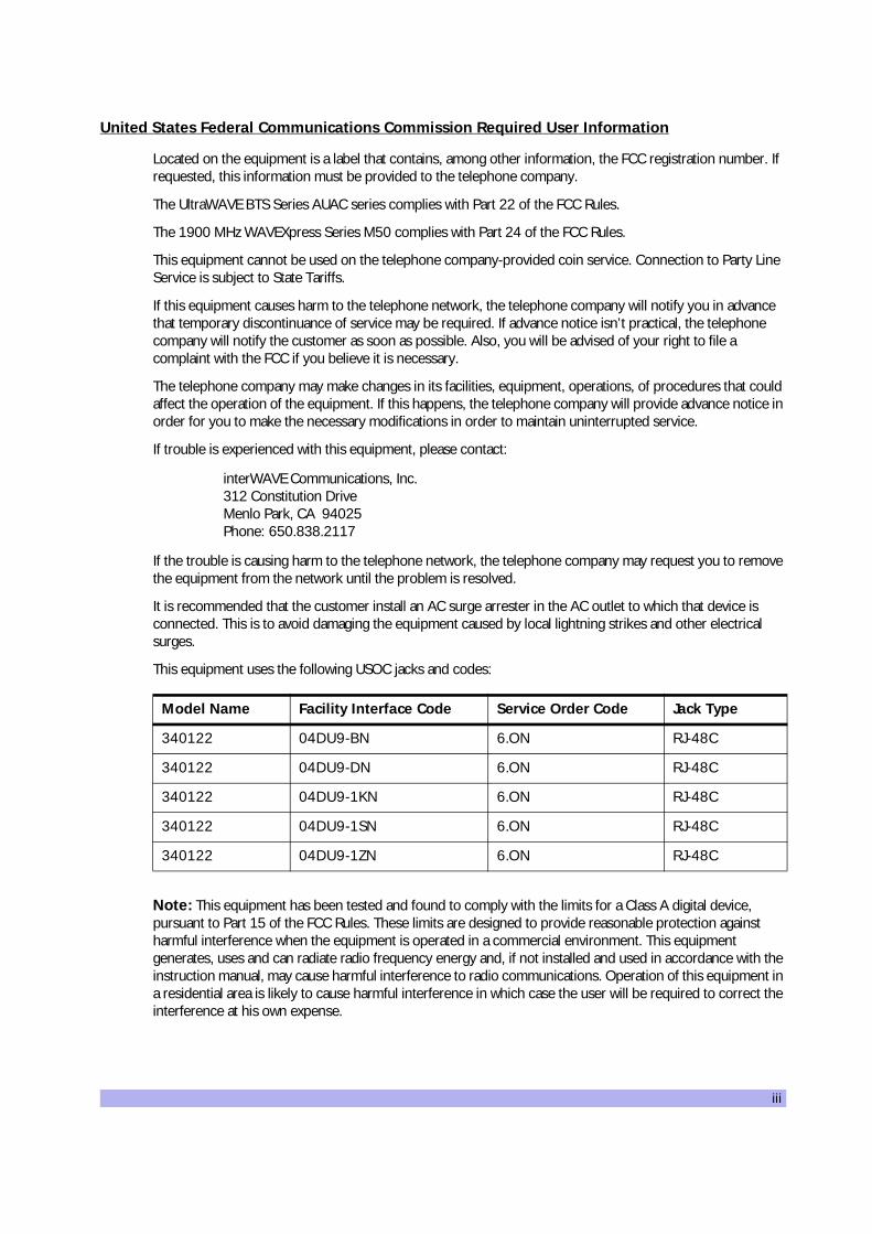
This equipment uses the following USOC jacks and codes:
Note: This equipment has been tested and found to comply with the limits for a Class A digital device, pursuant to Part 15 of the FCC Rules. These limits are designed to provide reasonable protection against harmful interference when the equipment is operated in a commercial environment. This equipment generates, uses and can radiate radio frequency energy and, if not installed and used in accordance with the instruction manual, may cause harmful interference to radio communications. Operation of this equipment in a residential area is likely to cause harmful interference in which case the user will be required to correct the interference at his own expense.
Model Name Facility Interface Code Service Order Code Jack Type
340122 04DU9-BN 6.ON RJ-48C
340122 04DU9-DN 6.ON RJ-48C
340122 04DU9-1KN 6.ON RJ-48C
340122 04DU9-1SN 6.ON RJ-48C
340122 04DU9-1ZN 6.ON RJ-48C

iv UltraWAVE BTS Installation and Commissioning Guide, Release 6.5A
Changes of modifications not expressly approved by interWAVE Communications, Inc. can void the user’s authority to operate the equipment.
Industry Canada Required User Information
CP-O1, Issue 8, Part 1, Section 14.1
NOTICE: The Industry Canada label identifies certified equipment. This certification means that the equipment meets certain telecommunications network protective, operational and safety requirements as prescribed in the appropriate Terminal Equipment Technical Requirements document(s). The Department does not guarantee the equipment will operate to the user’s satisfaction.
Before installing this equipment, users should ensure that it is permissible to be connected to the facilities of the local telecommunications company. The equipment must also be installed using an acceptable method of connection. The customer should be aware that compliance with the above conditions may not prevent degradation of service in some situations.
Repairs to certified equipment should be coordinated by a representative designated by the supplier. Any repairs or alterations made by the user to this equipment, or equipment malfunctions, may give the telecom-munications company cause to request the user to disconnect the equipment.
Users should ensure for their own protection that the electrical ground connections of the power utility, telephone lines and internal metallic water pipe system, if present, are connected together. This precaution may be particularly important in rural areas.
CAUTION: Users should not attempt to make such connections themselves, but should contact the appropriate electric inspection authority, or electrician, as appropriate.
The standard connecting arrangement (telephone jack type) for this equipment is CA81A.
CP-01, Issue 8, Part 1, Section 14.2
NOTICE: The Ringer Equivalence Number (REN) assigned to each terminal device provides an indication of the maximum number of terminals allowed to be connected to a telephone interface. The termination of an interface may consist of any combination of devices subject only to the requirement that the sum of the Ringer Equivalence Numbers of all the devices does not exceed 5.
This Class A digital apparatus complies with Canadian ICES-003.
Cet appareil numerique de la classe A est conforme a la norme NMB-003 du Canada.
This device complies with Industry Canada RSS-133 and SRSP-510.
v
Table of Contents
Welcome! . . . . . . . . . . . . . . . . . . . . . . . . . . . . . . . . . . . . . . . . . . . . . . . . . . . . . . . . . . . . . . . . . . . . . . . . ixAssumptions, Purpose, and Audience . . . . . . . . . . . . . . . . . . . . . . . . . . . . . . . . . . . . . . . . . . . . . . . . . . ixRelated Documentation . . . . . . . . . . . . . . . . . . . . . . . . . . . . . . . . . . . . . . . . . . . . . . . . . . . . . . . . . . . . . ixCustomer Support Services . . . . . . . . . . . . . . . . . . . . . . . . . . . . . . . . . . . . . . . . . . . . . . . . . . . . . . . . . . x
Return Materials Authorization . . . . . . . . . . . . . . . . . . . . . . . . . . . . . . . . . . . . . . . . . . . . . . . . . xiTraining . . . . . . . . . . . . . . . . . . . . . . . . . . . . . . . . . . . . . . . . . . . . . . . . . . . . . . . . . . . . . . . . . . . xi
Conventions Used in this Manual . . . . . . . . . . . . . . . . . . . . . . . . . . . . . . . . . . . . . . . . . . . . . . . . . . . . . .xii
Chapter 1 Unpacking and Configuration Verification . . . . . . . . . . . . . . . . . . . . . . . . . . . . . . . . . . . . . .1
1-1 Unpacking and Inspecting . . . . . . . . . . . . . . . . . . . . . . . . . . . . . . . . . . . . . . . . . . . . . . . . . . . . . . . 11-2 Inspect Components and Record Part Numbers . . . . . . . . . . . . . . . . . . . . . . . . . . . . . . . . . . . . . . 3
1-2.1 Identifying the System Configuration . . . . . . . . . . . . . . . . . . . . . . . . . . . . . . . . . . . . . . 41-2.2 Identifying Module Part and Serial numbers . . . . . . . . . . . . . . . . . . . . . . . . . . . . . . . . . 6
1-3 Verifying and Documenting Cards and Modules . . . . . . . . . . . . . . . . . . . . . . . . . . . . . . . . . . . . . . 81-3.1 Required Equipment . . . . . . . . . . . . . . . . . . . . . . . . . . . . . . . . . . . . . . . . . . . . . . . . . . . 81-3.2 RF Subrack Assembly . . . . . . . . . . . . . . . . . . . . . . . . . . . . . . . . . . . . . . . . . . . . . . . . . . 81-3.3 Baseband Subrack Assembly . . . . . . . . . . . . . . . . . . . . . . . . . . . . . . . . . . . . . . . . . . . . 8
1-4 Internal Cabling Overview . . . . . . . . . . . . . . . . . . . . . . . . . . . . . . . . . . . . . . . . . . . . . . . . . . . . . . 10
Chapter 2 Installation . . . . . . . . . . . . . . . . . . . . . . . . . . . . . . . . . . . . . . . . . . . . . . . . . . . . . . . . . . . . .11
2-1 Site Requirements . . . . . . . . . . . . . . . . . . . . . . . . . . . . . . . . . . . . . . . . . . . . . . . . . . . . . . . . . . . . 112-1.1 Environmental Conditions . . . . . . . . . . . . . . . . . . . . . . . . . . . . . . . . . . . . . . . . . . . . . . 112-1.2 Electrical Requirements . . . . . . . . . . . . . . . . . . . . . . . . . . . . . . . . . . . . . . . . . . . . . . . . 122-1.3 Chassis Requirements . . . . . . . . . . . . . . . . . . . . . . . . . . . . . . . . . . . . . . . . . . . . . . . . . 13
2-2 Mounting the BTS Chassis . . . . . . . . . . . . . . . . . . . . . . . . . . . . . . . . . . . . . . . . . . . . . . . . . . . . . . 142-3 Configuring the E1 or T1 Trunk Card . . . . . . . . . . . . . . . . . . . . . . . . . . . . . . . . . . . . . . . . . . . . . . 18
2-3.1 Configure Ground Jumpers on 75 Ohm E1 Cards . . . . . . . . . . . . . . . . . . . . . . . . . . . 182-3.2 Configure Cable Length DIP Switch Settings on T1 Cards . . . . . . . . . . . . . . . . . . . . . 23
2-4 Connecting Power and Ground Cables . . . . . . . . . . . . . . . . . . . . . . . . . . . . . . . . . . . . . . . . . . . . 252-4.1 Connecting the Grounding Cable . . . . . . . . . . . . . . . . . . . . . . . . . . . . . . . . . . . . . . . . 252-4.2 Connecting the Power Supplies . . . . . . . . . . . . . . . . . . . . . . . . . . . . . . . . . . . . . . . . . 25
2-5 Connecting E1 or T1 Trunk Cables . . . . . . . . . . . . . . . . . . . . . . . . . . . . . . . . . . . . . . . . . . . . . . . 282-5.1 E1 Cables . . . . . . . . . . . . . . . . . . . . . . . . . . . . . . . . . . . . . . . . . . . . . . . . . . . . . . . . . . . 282-5.2 T1 Cables . . . . . . . . . . . . . . . . . . . . . . . . . . . . . . . . . . . . . . . . . . . . . . . . . . . . . . . . . . 302-5.3 Connecting E1 or T1 Lines . . . . . . . . . . . . . . . . . . . . . . . . . . . . . . . . . . . . . . . . . . . . . 312-5.4 Direct Cabling Between Multiple UltraWAVE or WAVEXpress Systems . . . . . . . . . . . 312-5.5 Cabling External BTSs . . . . . . . . . . . . . . . . . . . . . . . . . . . . . . . . . . . . . . . . . . . . . . . . . 32
2-6 Connecting Antennas . . . . . . . . . . . . . . . . . . . . . . . . . . . . . . . . . . . . . . . . . . . . . . . . . . . . . . . . . . 322-6.1 Omni 1 TRX (O1) Configuration . . . . . . . . . . . . . . . . . . . . . . . . . . . . . . . . . . . . . . . . . 332-6.2 Omni 2 TRX (O2) Configuration . . . . . . . . . . . . . . . . . . . . . . . . . . . . . . . . . . . . . . . . . 342-6.3 Omni 3 TRX (O3) Configuration . . . . . . . . . . . . . . . . . . . . . . . . . . . . . . . . . . . . . . . . . 342-6.4 Omni 4 TRX (O4) Configuration . . . . . . . . . . . . . . . . . . . . . . . . . . . . . . . . . . . . . . . . . 34

vi UltraWAVE BTS Installation and Commissioning Guide, Release 6.5A
2-6.5 Omni 5 TRX (O5) Configuration . . . . . . . . . . . . . . . . . . . . . . . . . . . . . . . . . . . . . . . . . 352-6.6 Omni 6 TRX (O6) Configuration . . . . . . . . . . . . . . . . . . . . . . . . . . . . . . . . . . . . . . . . . 362-6.7 Omni 5 (05) and Omni 6 (O6) 25 Watt Configuration . . . . . . . . . . . . . . . . . . . . . . . . 362-6.8 Sectorized Two TRX (S11) Configuration . . . . . . . . . . . . . . . . . . . . . . . . . . . . . . . . . . 372-6.9 Sectorized Three TRX (S111) Configuration . . . . . . . . . . . . . . . . . . . . . . . . . . . . . . . . 372-6.10 Two Sector Four TRX (S22) Configuration . . . . . . . . . . . . . . . . . . . . . . . . . . . . . . . . 382-6.11 Three Sector Four TRX (S211) Configuration . . . . . . . . . . . . . . . . . . . . . . . . . . . . . . 382-6.12 Three Sector Five TRX (S221) Configuration . . . . . . . . . . . . . . . . . . . . . . . . . . . . . . . 392-6.13 Three Sector Six TRX (S222) Configuration . . . . . . . . . . . . . . . . . . . . . . . . . . . . . . . 392-6.14 Two Sector Five TRX (S32) Configuration . . . . . . . . . . . . . . . . . . . . . . . . . . . . . . . . . 402-6.15 Two Sector Six TRX (S33) Configuration . . . . . . . . . . . . . . . . . . . . . . . . . . . . . . . . . . 402-6.16 Two Sector Six TRX (S42) Configuration . . . . . . . . . . . . . . . . . . . . . . . . . . . . . . . . . . 412-6.17 RF Radiation Hazard . . . . . . . . . . . . . . . . . . . . . . . . . . . . . . . . . . . . . . . . . . . . . . . . . . 41
2-7 Connecting External Alarms . . . . . . . . . . . . . . . . . . . . . . . . . . . . . . . . . . . . . . . . . . . . . . . . . . . . . 432-8 Post Installation Cabling and Checks . . . . . . . . . . . . . . . . . . . . . . . . . . . . . . . . . . . . . . . . . . . . . . 46
Chapter 3 Off-Line Commissioning . . . . . . . . . . . . . . . . . . . . . . . . . . . . . . . . . . . . . . . . . . . . . . . . . . .47
3-1 Pre Off-Line Commissioning . . . . . . . . . . . . . . . . . . . . . . . . . . . . . . . . . . . . . . . . . . . . . . . . . . . . . 483-1.1 Visual Inspection . . . . . . . . . . . . . . . . . . . . . . . . . . . . . . . . . . . . . . . . . . . . . . . . . . . . . 48
3-2 Off-Line Commissioning the UltraWAVE BTS . . . . . . . . . . . . . . . . . . . . . . . . . . . . . . . . . . . . . . . . 503-2.1 Connecting the Craft PC to the ICP Processor Card . . . . . . . . . . . . . . . . . . . . . . . . . . 503-2.2 Starting XWindows Using the Craft PC . . . . . . . . . . . . . . . . . . . . . . . . . . . . . . . . . . . . 523-2.3 Power-On LED Tests . . . . . . . . . . . . . . . . . . . . . . . . . . . . . . . . . . . . . . . . . . . . . . . . . . 533-2.4 Establishing Serial Communications with the BTS . . . . . . . . . . . . . . . . . . . . . . . . . . . . 553-2.5 Verifying/Changing Boot Parameters . . . . . . . . . . . . . . . . . . . . . . . . . . . . . . . . . . . . . 56
3-3 Software verification using Craft PC . . . . . . . . . . . . . . . . . . . . . . . . . . . . . . . . . . . . . . . . . . . . . . . 583-3.1 Verifying the Current Software Version and Patch Level . . . . . . . . . . . . . . . . . . . . . . . 583-3.2 Checking the Flash Version Number . . . . . . . . . . . . . . . . . . . . . . . . . . . . . . . . . . . . . . 583-3.3 Running E1 or T1 POST Diagnostics . . . . . . . . . . . . . . . . . . . . . . . . . . . . . . . . . . . . . . 593-3.4 Verifying Telnet Communications with the BTS over Ethernet . . . . . . . . . . . . . . . . . . 603-3.5 Running TRX POST Diagnostics . . . . . . . . . . . . . . . . . . . . . . . . . . . . . . . . . . . . . . . . . . 613-3.6 Reviewing POST Results . . . . . . . . . . . . . . . . . . . . . . . . . . . . . . . . . . . . . . . . . . . . . . . 633-3.7 Rebooting the BTS after Running POST . . . . . . . . . . . . . . . . . . . . . . . . . . . . . . . . . . . 643-3.8 Terminating Serial Communications with the BTS . . . . . . . . . . . . . . . . . . . . . . . . . . . . 64
3-4 Exiting XWindows on the Craft PC . . . . . . . . . . . . . . . . . . . . . . . . . . . . . . . . . . . . . . . . . . . . . . . . 653-5 Upgrading the BTS Software Version (Flash) . . . . . . . . . . . . . . . . . . . . . . . . . . . . . . . . . . . . . . . . 663-6 Post Off-Line Commissioning . . . . . . . . . . . . . . . . . . . . . . . . . . . . . . . . . . . . . . . . . . . . . . . . . . . . 68
Chapter 4 Off-Line Commissioning of a Daisy Chain . . . . . . . . . . . . . . . . . . . . . . . . . . . . . . . . . . . . .69
4-1 Prerequisites to Daisy Chaining . . . . . . . . . . . . . . . . . . . . . . . . . . . . . . . . . . . . . . . . . . . . . . . . . . 694-2 Setting the Abis LAPD Signaling Timeslot . . . . . . . . . . . . . . . . . . . . . . . . . . . . . . . . . . . . . . . . . . . 70
Chapter 5 On-Line Commissioning . . . . . . . . . . . . . . . . . . . . . . . . . . . . . . . . . . . . . . . . . . . . . . . . . . .71
5-1 Pre On-Line Commissioning Requirements . . . . . . . . . . . . . . . . . . . . . . . . . . . . . . . . . . . . . . . . . 725-2 On-Line Commissioning . . . . . . . . . . . . . . . . . . . . . . . . . . . . . . . . . . . . . . . . . . . . . . . . . . . . . . . . 735-3 Antenna Cabling and Power Verification . . . . . . . . . . . . . . . . . . . . . . . . . . . . . . . . . . . . . . . . . . . 78

vii
5-3.1 Voltage Standing Wave Ratio (VSWR) Check . . . . . . . . . . . . . . . . . . . . . . . . . . . . . . . 785-3.2 Verifying BTS RF Performance without Racal . . . . . . . . . . . . . . . . . . . . . . . . . . . . . . . 785-3.3 Verifying TRX Output Power . . . . . . . . . . . . . . . . . . . . . . . . . . . . . . . . . . . . . . . . . . . . 785-3.4 RX BER Measurements . . . . . . . . . . . . . . . . . . . . . . . . . . . . . . . . . . . . . . . . . . . . . . . . 79
5-4 Post On-Line Commissioning Procedures . . . . . . . . . . . . . . . . . . . . . . . . . . . . . . . . . . . . . . . . . . 81
Checklist 1 Site Readiness Checklist . . . . . . . . . . . . . . . . . . . . . . . . . . . . . . . . . . . . . . . . . . . . . . . . . 83
Checklist 2 Installation Checklist . . . . . . . . . . . . . . . . . . . . . . . . . . . . . . . . . . . . . . . . . . . . . . . . . . . . 85
Checklist 3 Commissioning Checklist . . . . . . . . . . . . . . . . . . . . . . . . . . . . . . . . . . . . . . . . . . . . . . . . 87
Index . . . . . . . . . . . . . . . . . . . . . . . . . . . . . . . . . . . . . . . . . . . . . . . . . . . . . . . . . . . . . . . . . . . . . . . . . . 91

viii UltraWAVE BTS Installation and Commissioning Guide, Release 6.5A
(this page intentionally left blank)

ix
Preface
Welcome!
Welcome to the UltraWAVE BTS Installation and Commissioning Guide. This guide is written to provide the user with installation guidelines and procedures which will be required to set-up and initially configure the BTS.
Assumptions, Purpose, and Audience
This document is intended for an interWAVE trained field service engineer (FSE) or operator who performs local installation and commissioning at a customer site. The FSE or operator should be equipped with the necessary tools for installation and commissioning, and a basic understanding of the GSM cellular network. The FSE or Operator should also be familiar with the use of Craft PC and procedures conducted using the Craft PC.
interWAVE assumes that pre-installation project planning has occurred, and is documented via a site survey report. This site survey should include items such as the location of antennas, chassis, power connections and other interface accesses and temperature control equipment.
Microwave Radio Radiation Warning
Although interWAVE products do not use microwave radio antennas, the equipment is often mounted in the vicinity of microwave radio antennas. Under normal operating conditions, microwave radio equipment complies with the limits for human exposure to radio frequency (RF) fields adopted by the Federal Communications Commission (FCC). All interWAVE Communications, Inc. microwave radio equipment is designed so that under normal working conditions, microwave radiation directly from the radio is negligible when compared with the permissible limit of continuous daily exposure recommended in the United States by ANSI/IEEE C95.1-1991 (R1997), Safety Levels with Respect to Human Exposure to Radio Frequency Electromagnetic Fields, 3 kHz to 300 GHz.
Microwave signal levels that give rise to hazardous radiation levels can exist within transmitter power amplifiers, associated RF multiplexers, and antenna systems.
Related Documentation
All manuals are available on a documentation CD-ROM in Adobe portable document format or in an online format via our protected Internet site. To order documentation, please contact interWAVE Communications, Inc. Sales department online at http://www.iwv.com.
Never look into the open end of a waveguide or any other open RF connection as eyes are particularly vulnerable to radiation. Do not disconnect RF coaxial connectors, open microwave units, or break down any microwave screening while the radio equipment is operating.

x UltraWAVE BTS Installation and Commissioning Guide, Release 6.5A
Updates to this manual will be posted on the interWAVE Communications, Inc. Customer Service Website at http://www.iwv.com/custsupport. Registered interWAVE customers can access the interWAVE on-line information and support service, available 24 hours a day, seven days a week. The interWAVE on-line service provides users with a wealth of up-to-date information, with documents being added or updated each month.
Customer Support Services
interWAVE has regional customer service centers that handle day-to-day customer issues. Each center is staffed with a local technical support group. The exact services to be performed by the interWAVE Customer Service department are specified in a support contract. Below is an example of the types of services available:
• telephone support
• site surveys
• installations
• off-line and on-line commissioning
• network integration activities
• troubleshooting and fault isolation
• escalation of problems to appropriate interWAVE technical departments
interWAVE can physically perform all or a portion of these processes for the operator, as specified in the support contract. The Customer Service department can also provide documentation outlining corrective and preventive maintenance procedures and troubleshooting guides for fault isolation.
Contact your local Sales Support office, or interWAVE headquarters directly via the Internet at http://www.iwv.com.
If possible, please have the following information available when making a call:
• site number or name
• full description of product(s) (e.g., model and part number) and configuration
• serial number of product(s)
• purchase order number
For support on installing or configuring all interWAVE GSM, DCS or PCS equipment, contact your Regional interWAVE Customer Service Center at:
• +852.2574.1922 or [email protected] -- Asia and Pacific Rim
• +1.866.306.1263 or [email protected] -- North and South America, Europe, Africa, and Middle East
or via the Internet at http://www.iwv.com/custsupport.
xi
Return Materials Authorization
In the event that a depot repair or hardware replacement is required after contacting Customer Service, please contact interWAVE for return authorization. The following information is required by interWAVE:
• full description of the product(s): model and part number
• serial number of the product(s)
• purchase order number
• quantity that needs to be returned to interWAVE, if applicable
• description of observed problem
All interWAVE products carry a one year manufacturing warranty from the date of shipment. At the time of a request for a return authorization, if the product has exceeded the warranty period, interWAVE will require a new purchase order number to cover the cost of non-warranty repair.
Contact Sales Operations via the Internet at http://www.iwv.com or email at [email protected].
Training
interWAVE has developed an extensive series of training courses designed to teach you how to use our products. The courses are developed by a combination of subject matter experts and training specialists in order to create highly technical materials in modern training format. Each of our course offerings are designed around specific learning objectives that keep our classes on track to learning specific job skills related to interWAVE products.
The interWAVE training catalog contains a listing of the interWAVE training services available along with descriptions of each course. Our training materials are divided into specific subsystem training series, depending upon the topic and job requirements.
Contact Customer Service via the Internet at http://www.iwv.com or email at [email protected].

xii UltraWAVE BTS Installation and Commissioning Guide, Release 6.5A
Conventions Used in this Manual
The following type and style conventions are used in this manual:
Table 1 Conventions Used in This Manual
Convention Meaning
Body text Used for regular body text
Bold Indicates a menu or button choice
Command Indicates computer generated text and prompts
User Input Indicates user input
<hostname> In command syntax, indicates user-specified command line parameters
<variable> In body text, indicates user-specified command line parameters
[BRACKETS] Indicates a key on the keyboard or instrument
Provides relevant additional information
Provides important warning information that may affect operation of or maybe a potential threat to the system
Used to tell the reader to STOP what they are doing and to read important instructions that are vital to prevent equipment or software damage

Unpacking and Configuration Verification 1
OneUnpacking and Configuration Verification
10000
This chapter provides instructions for opening the shipping container and inspecting the contents. When you have completed the procedures in this chapter you will have confirmed that the hardware arrived undamaged, and that everything you ordered is present and configured correctly.
The procedures in this chapter include:
• Unpacking and inspecting the system. See Section 1-1.
• Inspect the system identification label and verify that this is the system you ordered. See Section 1-2.
• Inspect the system components, verify and record the part numbers. See Section 1-3.
1-1 Unpacking and Inspecting
Your interWAVE system was packed with great care, and all containers were inspected before shipment. Upon receipt of these packages, immediately inspect the outside of the shipping containers. If there is any visible damage, insist that a representative of the carrier be present when unpacking the contents.
Carefully inspect the system as it is unpacked. If any damage, such as dents or broken connections, is noticeable immediately notify the carrier as well as interWAVE Customer Service.
Store the shipping containers for future use. If the unit has to be returned for upgrade or service, the specially designed shipping containers assure adequate protection for the equipment. If for some reason the containers are not reusable or if they are misplaced, please contact interWAVE to order new containers.
The UltraWAVE BTS is shipped pre-configured in a locking cabinet assembly, shown in Figure 1-1.

2 UltraWAVE BTS Installation and Commissioning Guide, Release 6.5A
Doors are provided for access to the front and rear of the internal assemblies. To open the doors:
1 Insert the key provided into the lock and turn to unlock.
2 Depress the lock mechanism to release the door latch handle.
3 Turn the door handle to unlatch and open the door.
Figure 1-1 Locking Cabinet
��������

Unpacking and Configuration Verification 3
1-2 Inspect Components and Record Part Numbers
The UltraWAVE BTS is tested with all cards and modules installed in the chassis as ordered by the customer. In this section you will:
• Identify and record part and serial numbers
• Determine your system configuration
The unit is shipped assembled to your location. The assembled cabinet and subracks are pre-cabled for your configuration with the exception of the power supplies which will need to be installed. The individual components of the unit include:
• Cabinet (20U) with locking doors and external I/O interface ports
• RF subrack assembly
• Baseband subrack assembly
• Power supply subrack assembly
• PC cards and blank panels
• RF cards and modules
• Internal cabling
• Power supply modules
These components appear assembled without internal cabling in Figure 1-2.

4 UltraWAVE BTS Installation and Commissioning Guide, Release 6.5A
1-2.1 Identifying the System Configuration
Many configurations of the UltraWAVE BTS are available, from an omni one TRX (O1) to a three sector two TRX per sector (S222) system. Use this section to verify the configuration of your BTS.
1 Locate the main configuration label on the exterior of your shipping container as shown in Figure 1-3.
This configuration label details the system configuration and all of the modules and cards contained in the system.
Figure 1-2 UltraWAVE BTS Components
���� ���
�����������
�������������
�������� ������
��������
������� ��
������ ��� �� ���
��� !��������!�
����!���� !��������!�
������ ��� � !��������!�
"#$�#�
�$�
���
�"���
� �
�"���
� �%$%�&'
%$%�&'
��������������������������(#������
�������������������������'(#������
���")&
"#$�#����
�$�
'�#
�"#
�#��
��������������������������(#������
�������������������������'(#������
���
*���#
"#$�#�
�$�
��+�
��+%
��&),�$-
��".�
���
*���#
"#$�#�
�$�
��+�
��+%
��&),�$-
��".�
���
*���#
"#$�#�
�$�
��+�
��+%
��&),�$-
��".�
���
*���#
"#$�#�
�$�
��+�
��+%
��&),�$-
��".�
���
*���#
"#$�#�
�$�
��+�
��+%
��&),�$-
��".�
���
*���#
"#$�#�
�$�
��+�
��+%
��&),�$-
��".�
�#�.�
".��.�
�%.$�
"�� "#
�#�.�
".��.�
�%.$�
"�� "#
�#�.�
".��.�
�%.$�
"�� "#
�%��#
%#�*�/
%#�&%�#
���
�$�
"#$�#�
"#
"��
���
���
���
��0
���*��
���*��
�%��#
���
���
���
��0
�%��#
%#�*�/
%#�&%�#
���
�$�
"#$�#�
"#
"��
���
���
���
��0
���*��
���*��
�%��#
���
���
���
��0
�%��#
%#�*�/
%#�&%�#
���
�$�
"#$�#�
"#
"��
���
���
���
��0
���*��
���*��
�%��#
���
���
���
��0
� � � � 0 1 2 � 3
� � � � 10
��!4���5��.6
����2���

Unpacking and Configuration Verification 5
2 Locate the model number and using Table 1-1 decode the first seven digits for the chassis type and system configuration of the BTS.
The first four letters denote the type of interWAVE system, in this case an UltraWAVE BTS. The next two or three digits denote the BTS configuration.
Figure 1-3 Main Configuration Label
Table 1-1 Model Number Details
Digit Location Contents Configuration
First four letters AUAC UltraWAVE BTS
���������� ����������������������� ��
�������� ��������������������
�� �!�"�� ���# ��$���&�4�'�78� �����9���:4����� ���
%�& �'
()� #���*� ���� �+�,(�%!���*(��-.�(./�000000
�� �������������4��4�� ��;;;;;;;
��1��2 �342 ���&&&&&��������5���6�����
;;;;;;+;;;
�� �������������4��4��
�� �������������4��4��
����� !�� ���4��� !��
��;;;;;;;
;;;;;;+;;; �� �������������4��4�� ��;;;;;;;
;;;;;;+;;; �� �������������4��4�� ��;;;;;;;
;;;;;;+;;; �� �������������4��4�� ��;;;;;;;
;;;;;;+;;; �� �������������4��4�� ��;;;;;;;
;;;;;;+;;;
��������

6 UltraWAVE BTS Installation and Commissioning Guide, Release 6.5A
Using the example in Figure 1-3, the model number is AUACS24 which corresponds to an UltraWAVE BTS configured for three sectors with two TRXs per sector (S222).
3 Record your model number and configuration in the Installation Checklist.
1-2.2 Identifying Module Part and Serial numbers
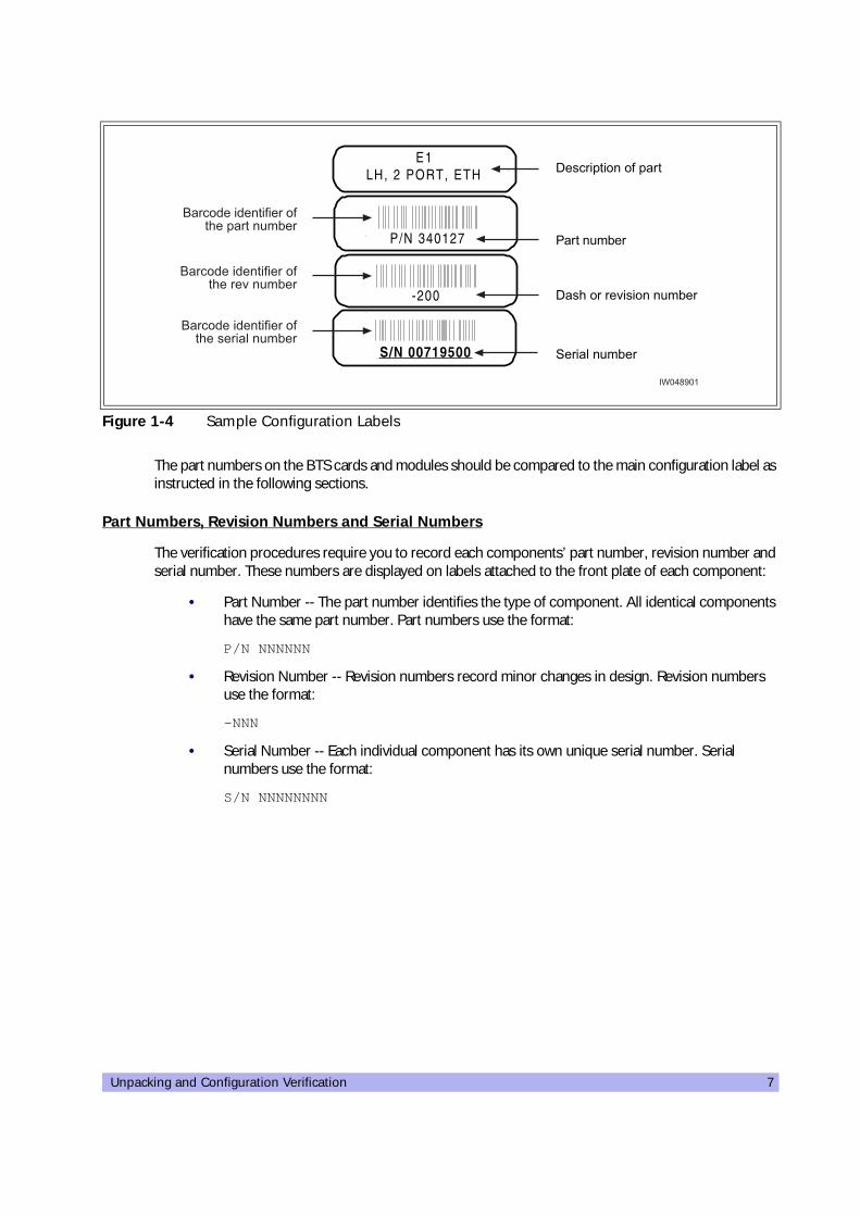
The factory places up to four configuration labels on the front of each BTS card, module, and chassis to help identify the system configuration. The labels identify the:
• Part description
• Part number
• Revision or dash number
• Serial number
An example of the configuration labels appears in Figure 1-4:
Next two or three digits
O1 Omni single TRX (O1); 50 watts, 2 antennas
O2 Omni two TRX (O2); 50 watts, 2 antennas
O3 Omni three TRX (O3); 25 watts, 2 antennas
O4 Omni four TRX (O4); 25 watts, 2 antennas
O5 Omni five TRX (O5); 15 watts, 2 antennas or 25 watts, 3 antennas
O6 Omni six TRX (O6); 15 watts, 2 antennas or 25 watts, 3 antennas
S11 Two sector, one TRX per sector (S11); 50 watt, 4 antennas
S13 Three sector, one TRX per sector (S111); 50 watt, 6 antennas
S21 Two sector, two TRXs per sector (S22); 50 watt, 4 antennas
S22 Three sector, two TRXs in one sector and one TRX in two sectors (S211); 50 watt, 6 antennas
S23 Three sector, two TRXs in two sectors and one TRX in one sector (S221); 50 watt, 6 antennas
S24 Three sector, two TRXs per sector (S222); 50 watt, 6 antennas
S32 Two sector, three TRXs in one sector and two in the other (S32); 25 watt, 4 antennas
S33 Two sector, three TRXs per sector (S33); 25 watt, 4 antennas
S41 Two sector, four TRXs in one sector, two in the other (S42); 25 watt, 4 antennas
Table 1-1 Model Number Details (continued)
Digit Location Contents Configuration
Unpacking and Configuration Verification 7
The part numbers on the BTS cards and modules should be compared to the main configuration label as instructed in the following sections.
Part Numbers, Revision Numbers and Serial Numbers
The verification procedures require you to record each components’ part number, revision number and serial number. These numbers are displayed on labels attached to the front plate of each component:
• Part Number -- The part number identifies the type of component. All identical components have the same part number. Part numbers use the format:
P/N NNNNNN
• Revision Number -- Revision numbers record minor changes in design. Revision numbers use the format:
-NNN
• Serial Number -- Each individual component has its own unique serial number. Serial numbers use the format:
S/N NNNNNNNN
Figure 1-4 Sample Configuration Labels
���������������
�� �������
����
�����������
*����4��4���<����
����� !��
*��=����:4�4��� !��
'��4��� !��
�������4����4<4���<�=������ !��
�������4����4<4���<�=���:� !��
�������4����4<4���<�=����4��� !��
���03>��

8 UltraWAVE BTS Installation and Commissioning Guide, Release 6.5A
1-3 Verifying and Documenting Cards and Modules
The cabinet contains three subrack assemblies:
• The RF subrack contains the BTS RF modules which are responsible for RF power amplifica-tion, duplexing and combining when required for each configuration.
• The baseband subrack assembly contains the main processing, trunking and TRX cards.
• The power supply subrack assembly contains up to three power supply modules.
1-3.1 Required Equipment
To verify and record your system configuration, you need:
• A copy of the Shipping Checklist. It should be one of the papers inside the shipping container.
• A copy of Checklist 2
1-3.2 RF Subrack Assembly
The RF subrack provides six slots, starting on the left with slot 0. Depending on your BTS configuration, up to three slots will be required for RF modules. These modules are shipped pre-installed and cabled from the factory.
1 Locate the configuration part and serial numbers on your RF modules. Figure 1-4 illustrates a sample of these labels.
2 Write down the part number, revision number and serial number in the Installation Checklist.
3 Compare the part numbers to the RF module part numbers on the main configuration label and shipping checklist.
1-3.3 Baseband Subrack Assembly
The baseband subrack provides nine slots, starting on the left with slot 0. The following table shows the card cage assignments in the baseband subrack assembly:
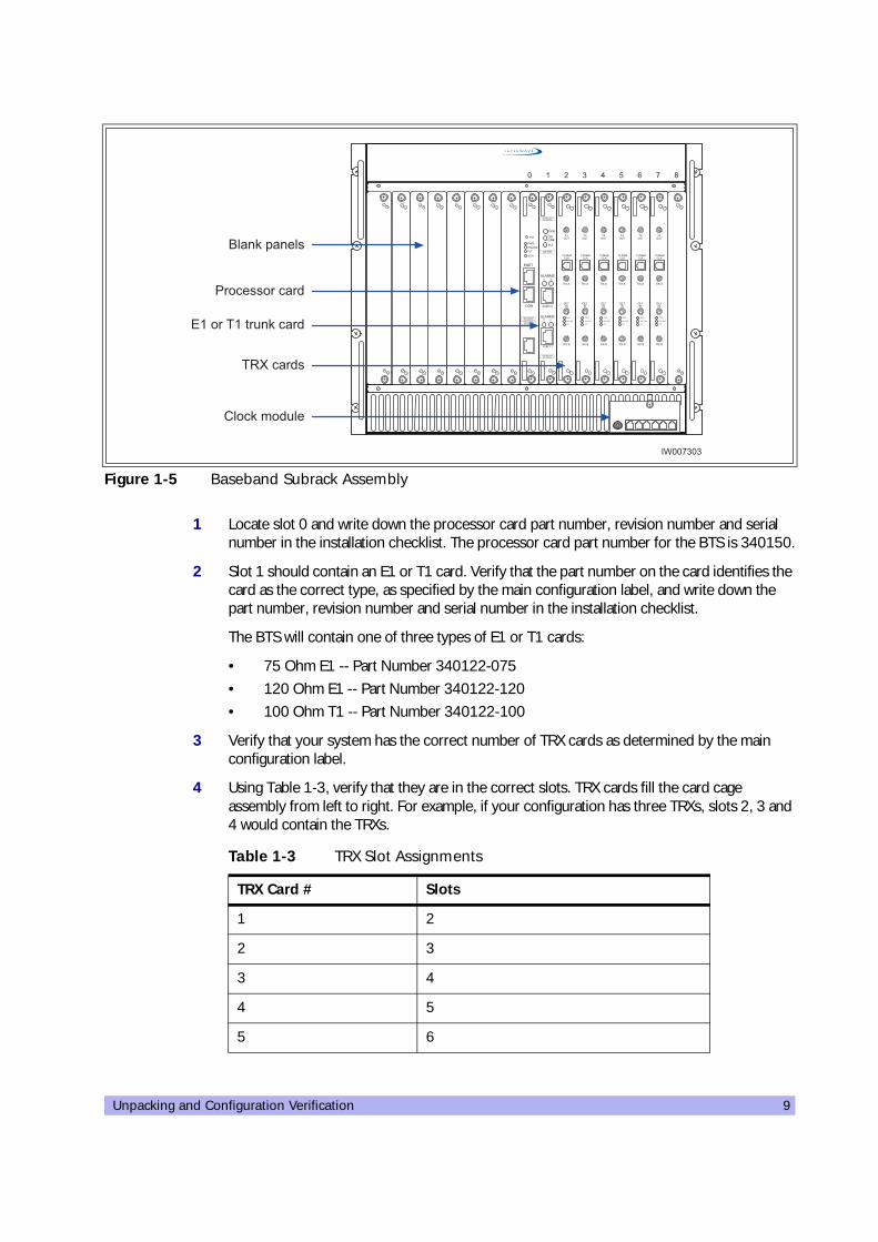
Use the following procedure to identify and record your system components. See Figure 1-5 for component locations:
Table 1-2 Card Cage Slot Assignments
Card Slots Width (Slots) Function
Processor card 0 1 This is an ICP processor card.
E1 or T1 1 1 E1 or T1 card provides 2 E1 or T1 lines
TRX 2, 3, 4, 5, 6, 7 1 Each TRX manages 8 radio channels.
Unpacking and Configuration Verification 9
1 Locate slot 0 and write down the processor card part number, revision number and serial number in the installation checklist. The processor card part number for the BTS is 340150.
2 Slot 1 should contain an E1 or T1 card. Verify that the part number on the card identifies the card as the correct type, as specified by the main configuration label, and write down the part number, revision number and serial number in the installation checklist.
The BTS will contain one of three types of E1 or T1 cards:
• 75 Ohm E1 -- Part Number 340122-075
• 120 Ohm E1 -- Part Number 340122-120
• 100 Ohm T1 -- Part Number 340122-100
3 Verify that your system has the correct number of TRX cards as determined by the main configuration label.
4 Using Table 1-3, verify that they are in the correct slots. TRX cards fill the card cage assembly from left to right. For example, if your configuration has three TRXs, slots 2, 3 and 4 would contain the TRXs.
Figure 1-5 Baseband Subrack Assembly
Table 1-3 TRX Slot Assignments
TRX Card # Slots
1 2
2 3
3 4
4 5
5 6
�����������
�������������
�������� ������
��������
������� ��
��������
"#$�#�
�$�
���
�"���
� �
�"���
� �%$%�&'
%$%�&'
��������������������������(#������
�������������������������'(#������
���")&
"#$�#����
�$�
'�#
�"#
�#��
��������������������������(#������
�������������������������'(#������
���
*���#
"#$�#�
�$�
��+�
��+%
��&),�$-
��".�
���
*���#
"#$�#�
�$�
��+�
��+%
��&),�$-
��".�
���
*���#
"#$�#�
�$�
��+�
��+%
��&),�$-
��".�
���
*���#
"#$�#�
�$�
��+�
��+%
��&),�$-
��".�
���
*���#
"#$�#�
�$�
��+�
��+%
��&),�$-
��".�
���
*���#
"#$�#�
�$�
��+�
��+%
��&),�$-
��".�
� � � � 0 1 2 � 3

10 UltraWAVE BTS Installation and Commissioning Guide, Release 6.5A
5 For each TRX card, write down the part number, revision number and serial number in the installation checklist.
6 Verify that all empty slots have blank panels covering them.
7 Check the shipping invoice and verify that the system has the correct number of power modules (2 or 3). If the third power module is not installed, verify that the slot is covered by a blank panel.
8 For each power module, write down the part number, revision number and serial number in the installation checklist.
9 Verify that the clock module is installed. Write down its part number, revision number and serial number in the installation checklist.
10 Verify all empty slots are covered by blank panels. These are necessary for cooling and to meet RF emission standards.
1-4 Internal Cabling Overview
Cabling inside the BTS cabinet is routed to connectors accessible on the outside of the cabinet assembly. The internal cabling connects the E1 or T1 card to the external interface cable plate interface. Antenna connections are also routed internally to provide an N-type connector on the top of the cabinet.
The internal cabling of the BTS depends on the configuration ordered by the customer. It is completed by the manufacturer. Due to its complexity, it is not recommended for you to move or disconnect internal cabling. Schematics of the internal RF cabling are provided in Appendix 1.
Proceed to Chapter Two to install your BTS.
6 7
Note: Systems equipped with less than six TRXs will have blank panels covering the empty slots.
Extreme care should be used when working around SMA cables, as misalignment or loosening of the cable with the connectors can damage both parts and degrade the cable's performance.
Table 1-3 TRX Slot Assignments
TRX Card # Slots

Installation 11
TwoInstallation
20000
This chapter provides instructions for installing and configuring the hardware. This includes:
• Verifying site requirements
• Mounting the chassis in its permanent location
• Configuring the E1 or T1 trunk card(s)
• Making the external connections to the BTS
2-1 Site Requirements
Before a site is chosen or equipment installed, a site survey must be carried out. The site survey checklist assists the surveyor with the inspection and the collection of site specific information such as environmental conditions, electrical requirements, and mechanical requirements
The site survey checklist must be completed before installation begins. Note that the necessary steps for site readiness are listed in Checklist 1.The interWAVE Network Implementation Manual provides additional detailed site requirements.
The site readiness checklist assists the field service engineer or operator to ensure that the site is ready for equipment installation. It includes information about:
• Environmental conditions
• Electrical requirements
• Chassis requirements
The site readiness checklist is located in Checklist 1, it must be completed as part of the installation process.
2-1.1 Environmental Conditions
The BTS is designed to operate indoors only. To facilitate long-term operability and durability of the BTS, observe specific environmental constraints.
Before installing the BTS, ensure that the operating environment maintains a temperature within the range shown in Table 2-1.
Make sure the ambient temperature around the unit (which may be higher than the room temperature) is within the limit specified for the unit.

12 UltraWAVE BTS Installation and Commissioning Guide, Release 6.5A
2-1.2 Electrical Requirements
The BTS is specified to operate on either AC or DC power. Requirements for the BTS are dependent on the number of TRX cards supported.
Power Options
Main power supply options for the BTS are:
• 110 VAC, 50-60 Hz
• 220 VAC, 50-60 Hz
• -48 VDC
Table 2-2 shows the typical current requirements for the BTS AC power mains.
Table 2-1 Operating Environment
Humidity (non-condensing)
Temperature (Celsius)
Temperature (Fahrenheit)
Maximum 90% 55 degrees 131 degrees
Minimum 10% -5 degrees 23 degrees
Table 2-2 Input Power Requirements
Product configuration Requirement for 120 or 220 VAC
One TRX 410 watts
Two TRXs 715 watts
Three TRXs 1010 watts
Four TRXs 1320 watts
Five TRXs 1630 watts
Six TRXs 1925 watts
Table 2-3 Power Specifications
Power Requirements Specification
BTS voltage range: 115 VAC 90 to132 VAC, 47 to 63 Hz
BTS power protection: 115 VAC Dedicated 20 amp circuit breaker
BTS voltage range: 230 VAC 187 to 264 VAC, 47 to 63 Hz
BTS power protection: 230 VAC Dedicated 10 amp circuit breaker
BTS voltage range: -48 VDC -41 to -60 VDC
Installation 13
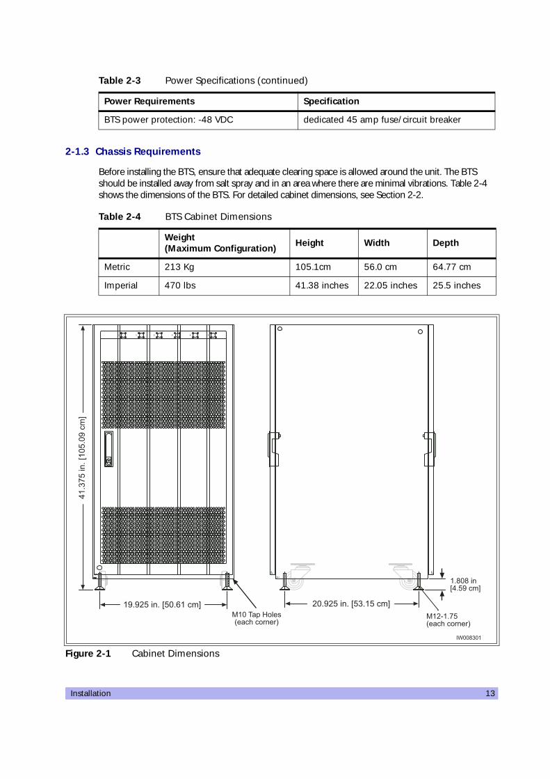
2-1.3 Chassis Requirements
Before installing the BTS, ensure that adequate clearing space is allowed around the unit. The BTS should be installed away from salt spray and in an area where there are minimal vibrations. Table 2-4 shows the dimensions of the BTS. For detailed cabinet dimensions, see Section 2-2.
BTS power protection: -48 VDC dedicated 45 amp fuse/circuit breaker
Table 2-4 BTS Cabinet Dimensions
Weight (Maximum Configuration) Height Width Depth
Metric 213 Kg 105.1cm 56.0 cm 64.77 cm
Imperial 470 lbs 41.38 inches 22.05 inches 25.5 inches
Figure 2-1 Cabinet Dimensions
Table 2-3 Power Specifications (continued)
Power Requirements Specification
����������������
���������������� ��������
*""�?�/
�%�?��%�?�/
�� �� 10
�.����.�����
�.�����
�%�?'/
*""�?
'/
*""�?
'/
�.�����
�.����.�����
��7>�14�7@1�7�1�A&��+�7�15���=������6
�73�34�@071>�A
�>7>�14�7@1�72��A
0�7��1
4�7@��
17�>
�A
����3���
&�����)����5���=������6
14 UltraWAVE BTS Installation and Commissioning Guide, Release 6.5A
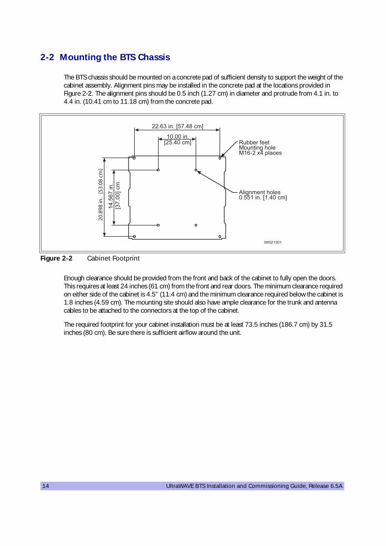
2-2 Mounting the BTS Chassis
The BTS chassis should be mounted on a concrete pad of sufficient density to support the weight of the cabinet assembly. Alignment pins may be installed in the concrete pad at the locations provided in Figure 2-2. The alignment pins should be 0.5 inch (1.27 cm) in diameter and protrude from 4.1 in. to 4.4 in. (10.41 cm to 11.18 cm) from the concrete pad.
Enough clearance should be provided from the front and back of the cabinet to fully open the doors. This requires at least 24 inches (61 cm) from the front and rear doors. The minimum clearance required on either side of the cabinet is 4.5” (11.4 cm) and the minimum clearance required below the cabinet is 1.8 inches (4.59 cm). The mounting site should also have ample clearance for the trunk and antenna cables to be attached to the connectors at the top of the cabinet.
The required footprint for your cabinet installation must be at least 73.5 inches (186.7 cm) by 31.5 inches (80 cm). Be sure there is sufficient airflow around the unit.
Figure 2-2 Cabinet Footprint
� !!��<���&� ��4�B=���&�2+�;0������
��
����
���
���
���
�
��72�4�7 @1�703�A
%�4B����=�����711�4�7@�70��A
��7��4�7@�170��A
�0712�
4�7
@��7��
A�
��������
Installation 15
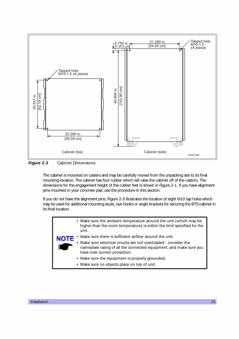
The cabinet is mounted on casters and may be carefully moved from the unpacking site to its final mounting location. The cabinet has four rubber which will raise the cabinet off of the castors. The dimensions for the engagement height of the rubber feet is shown in Figure 2-1. If you have alignment pins mounted in your concrete pad, use the procedure in this section.
If you do not have the alignment pins, Figure 2-3 illustrates the location of eight M10 tap holes which may be used for additional mounting studs, eye hooks or angle brackets for securing the BTS cabinet in its final location.
Figure 2-3 Cabinet Dimensions
• Make sure the ambient temperature around the unit (which may be higher than the room temperature) is within the limit specified for the unit.
• Make sure there is sufficient airflow around the unit.• Make sure electrical circuits are not overloaded - consider the
nameplate rating of all the connected equipment, and make sure you have over current protection.
• Make sure the equipment is properly grounded.• Make sure no objects place on top of unit.
��7�3�4�7@1271>�A
��710�
4�7
@1�7�>
�A
������=���&��+�71;0������
��7�3�4�7@107�1�A
0�7>�0
4�7
@���
7>��
A
�7�1�4�7@�7>�A�
��!4���5�4��6��!4���5���6
������=���&��+�71;0������
��������
16 UltraWAVE BTS Installation and Commissioning Guide, Release 6.5A
Required Materials
• Angle brackets
• Four M10 machine screws and washers
Required Tools
• 15 mm open end wrench
Installation Instructions
1 Move the cabinet into its final location. If using alignment pins to prevent movement, move the cabinet into position over the pins.
2 Lower the each of the rubber feet until each reaches the concrete pad.
3 Using the 15 mm open end wrench, lower each foot until the casters are raised from the concrete floor, approximately 0.25 in. (0.65 cm).
4 Remove the casters from the bottom of the cabinet.
5 Lower the cabinet to within 4.1 in. to 4.4 in. (10.41 cm to 11.18 cm) of the concrete pad. If you are using alignment pins, lower the cabinet until the pins should enter the alignment holes no more than 0.25 in. (0.6 cm). Do not lower the cabinet too far over alignment pins as they may puncture internal components.
6 Secure locking nuts on foot studs.
7 Secure the cabinet using customer-provided 10 mm studs.
Rack Mount Advisory
To prevent bodily injury when mounting or servicing this unit in a rack, you must take special precautions to ensure that the system remains stable. The following guidelines are provided to ensure your safety:
• This unit should be mounted at the bottom of the rack if it is the only unit in the rack.
• When mounting this unit in a partially filled rack, load the rack from the bottom to the top with the heaviest component at the bottom of the rack.
• If the rack is provided with stabilizing devices, install the stabilizers before mounting or servicing the unit in the rack.
Attention: Pour éviter toute blessure corporelle pendant les opérations de montage ou de réparation de cette unité en casier, il convient de prendre des précautions spéciales afin de maintenir la stabilité du système. Les directives ci-dessous sont destinées à assurer la protection du personnel :
• Si cette unité constitue la seule unité montée en casier, elle doit être placée dans le bas.
You may use the additional M10 tap holes to secure the cabinet as site-specific conditions allow.
Installation 17
• Si cette unité est montée dans un casier partiellement rempli, charger le casier de bas en haut en plaçant l'élément le plus lourd dans le bas.
• Si le casier est équipé de dispositifs stabilisateurs, installer les stabilisateurs avant de monter ou de réparer l'unité en casier.
Warnung: Zur Vermeidung von Körperverletzung beim Anbringen oder Warten dieser Einheit in einem Gestell müssen Sie besondere Vorkehrungen treffen, um sicherzustellen, daß das System stabil bleibt. Die folgenden Richtlinien sollen zur Gewährleistung Ihrer Sicherheit dienen:
• Wenn diese Einheit die einzige im Gestell ist, sollte sie unten im Gestell angebracht werden.
• Bei Anbringung dieser Einheit in einem zum Teil gefüllten Gestell ist das Gestell von unten nach oben zu laden, wobei das schwerste Bauteil unten im Gestell anzubringen ist.
• Wird das Gestell mit Stabilisierungszubehör geliefert, sind zuerst die Stabilisatoren zu install-ieren, bevor Sie die Einheit im Gestell anbringen oder sie warten.

18 UltraWAVE BTS Installation and Commissioning Guide, Release 6.5A
2-3 Configuring the E1 or T1 Trunk Card
This section describes how to configure E1 or T1 trunk cards.
These procedures designed for E1 or T1 cards that are shipped pre-configured in a system. To configure E1 or T1 cards that are shipped as configured or unconfigured replacements, see Appendix 1.
Your system is shipped from the manufacturer configured with the correct cards for your site-specific application. These can be 100 Ohm T1, 75 Ohm E1, or 120 Ohm E1. All cards are shipped with the appropriate connectors.
Table 2-5 lists the cards and the procedures that apply to each card type.
2-3.1 Configure Ground Jumpers on 75 Ohm E1 Cards
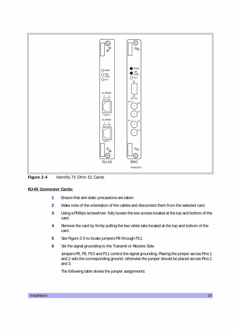
Two types of dual port 75-Ohm E1 cards exist. They are differentiated only by their connector types— either BNC or RJ-45 — on the front panel of the card.
1 Open the front cabinet door and locate the 75 Ohm E1 card in the baseband subrack assembly.
2 Identify your E1 card and proceed to the appropriate subsection. For RJ-45 cards, continue with the procedure below. For BNC cards, proceed to “BNC Connector Cards” on page 22.
Cable runs of greater than 600 meters (1968 feet) are not supported directly from the card. If you are attempting a longer cable run between interWAVE chassis please contact Customer Service to determine if you need a repeater for your application.
Table 2-5 Trunk Cards and Procedures
Label Description Operation
75 Ohm 75 Ohm E1 board Set the ground to the Transmit or Receive side using the jumpers. See Section 2-3.1
120 Ohm 120 Ohm E1 Board No configuration is required
100 Ohm 100 Ohm T1 Board
Configure the DIP switch based on cable length to the DSX-1 demarcation point. See Section 2-3.2.NOTE: No configuration is required unless connecting to a DSX1 demarcation point greater than 133 ft.
Installation 19
RJ-45 Connector Cards:
1 Ensure that anti-static precautions are taken.
2 Make note of the orientation of the cables and disconnect them from the selected card.
3 Using a Phillips screwdriver, fully loosen the two screws located at the top and bottom of the card.
4 Remove the card by firmly pulling the two white tabs located at the top and bottom of the card.
5 See Figure 2-5 to locate jumpers P8 through P11.
6 Set the signal grounding to the Transmit or Receive Side.
Jumpers P8, P9, P10 and P11 control the signal grounding. Placing the jumper across Pins 1 and 2 sets the corresponding ground; otherwise the jumper should be placed across Pins 2 and 3.
The following table shows the jumper assignments:
Figure 2-4 Identify 75 Ohm E1 Cards
���>����
��
��
��
��
"#$�#�
���
�$�
�'+���
��+�
��+�
�#�
�"���
� �
�"���
� �%$%�&'
�$�
"#$�#�
��
%$%�&'
�C+01
20 UltraWAVE BTS Installation and Commissioning Guide, Release 6.5A
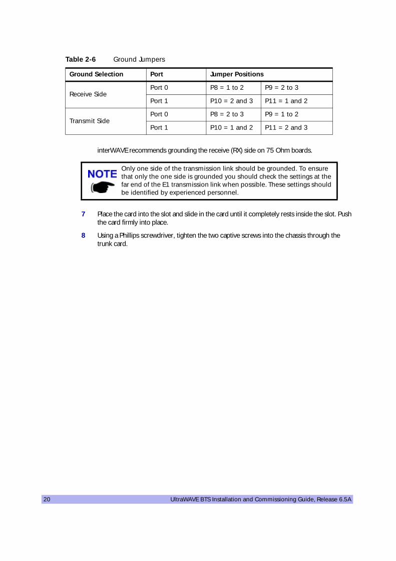
interWAVE recommends grounding the receive (RX) side on 75 Ohm boards.
7 Place the card into the slot and slide in the card until it completely rests inside the slot. Push the card firmly into place.
8 Using a Phillips screwdriver, tighten the two captive screws into the chassis through the trunk card.
Table 2-6 Ground Jumpers
Ground Selection Port Jumper Positions
Receive SidePort 0 P8 = 1 to 2 P9 = 2 to 3
Port 1 P10 = 2 and 3 P11 = 1 and 2
Transmit SidePort 0 P8 = 2 to 3 P9 = 1 to 2
Port 1 P10 = 1 and 2 P11 = 2 and 3
Only one side of the transmission link should be grounded. To ensure that only the one side is grounded you should check the settings at the far end of the E1 transmission link when possible. These settings should be identified by experienced personnel.

Installation 21
Figure 2-5 shows the location of the grounding jumpers
Figure 2-5 Ground Jumpers (P8 through P11)
C�
"# � � 0� 1 2 � 3
���23��0
�3
���
���
�>
�C0
1�D�
�D�7�2
��233��
�C0
1
�.'�
�.'�
�.'�
�.'�
�.'�
�.'�
�.'�
�.'�
��$%8#"#�
E
��$%8#"#�
E
��$%8#"#�
E
��$%8#"#�
E
�D�
�D�7�2
��233��
111+
�>0�
111+
�>0�
��+3���
��
2�
0�
3��
��
��
77777)"'�77777
��+3���
��
2�
0�
3��
��
��
77777)"'�77777
�����
�����
��F�� ��
��F�� ��
C ������#�7���1
C ������4�4���9�����3+���
��F�� ��
��F�� ��

22 UltraWAVE BTS Installation and Commissioning Guide, Release 6.5A
BNC Connector Cards
By placing a jumper between pins 1 and 2 of headers P4 (port 1) and P6 (port 2), the outer conductor of the dual port BNC 75 Ohm E1 card is grounded. This adheres to the ITU G.703 specification, which states that the receive coaxial pair must be floating, but with the option to ground.
The BTS is shipped with 4 jumpers in place which ground both the transmit and the receive coaxial pair. It is mandatory that the transmit pair is grounded. However, whether the receive pair is grounded is determined by the customer equipment to which the BSC is connected.
The configuration of these jumpers can be changed at this point.
Tools Required
• Phillips screwdriver
• Electrostatic wrist strap, provided with the BTS
Procedure
1 Place the supplied electrostatic wrist strap around your wrist. Attach the metallized tape of the wrist strap to the closest ground, for example, to the chassis of the BTS.
2 Unscrew the 75 Ohm dual port E1 card from the chassis, and pull it halfway out.
3 Look for the four jumpers silk-screened P3, P4, P5, and P6, located next to the external connectors on the dual port E1 card. See Figure 2-6
• A jumper connects pins 1 and 2 of P4 and P6. This ensures that the outer conductor is grounded. It is mandatory that these jumpers be installed in this configuration.
• A jumper connects pins 1 and 2 of P3 and P5. Remove these jumpers if the receive pair must be floating. Keep these jumpers installed if the receive pair is to be grounded.
.
Figure 2-6 Placement of the Jumper for Ports P3-P6
���
��������
����������� �����
���������!"�"�#����$��������
�1����4:�
���
�0�����4�
���
���
������4:�
�2�����4�
Installation 23
After the E1 card jumpers are checked for their correct placement, reinsert the dual port E1 card in the chassis, and screw it into place.
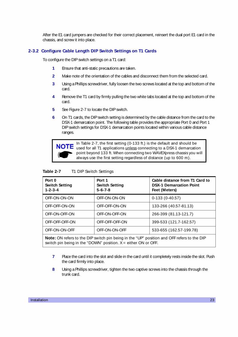
2-3.2 Configure Cable Length DIP Switch Settings on T1 Cards
To configure the DIP switch settings on a T1 card:
1 Ensure that anti-static precautions are taken.
2 Make note of the orientation of the cables and disconnect them from the selected card.
3 Using a Phillips screwdriver, fully loosen the two screws located at the top and bottom of the card.
4 Remove the T1 card by firmly pulling the two white tabs located at the top and bottom of the card.
5 See Figure 2-7 to locate the DIP switch.
6 On T1 cards, the DIP switch setting is determined by the cable distance from the card to the DSX-1 demarcation point. The following table provides the appropriate Port 0 and Port 1 DIP switch settings for DSX-1 demarcation points located within various cable distance ranges.
7 Place the card into the slot and slide in the card until it completely rests inside the slot. Push the card firmly into place.
8 Using a Phillips screwdriver, tighten the two captive screws into the chassis through the trunk card.
In Table 2-7, the first setting (0-133 ft.) is the default and should be used for all T1 applications unless connecting to a DSX-1 demarcation point beyond 133 ft. When connecting two WAVEXpress chassis you will always use the first setting regardless of distance (up to 600 m).
Table 2-7 T1 DIP Switch Settings
Port 0 Switch Setting 1-2-3-4
Port 1 Switch Setting 5-6-7-8
Cable distance from T1 Card to DSX-1 Demarcation Point Feet (Meters)
OFF-ON-ON-ON OFF-ON-ON-ON 0-133 (0-40.57)
OFF-OFF-ON-ON OFF-OFF-ON-ON 133-266 (40.57-81.13)
OFF-ON-OFF-ON OFF-ON-OFF-ON 266-399 (81.13-121.7)
OFF-OFF-OFF-ON OFF-OFF-OFF-ON 399-533 (121.7-162.57)
OFF-ON-ON-OFF OFF-ON-ON-OFF 533-655 (162.57-199.78)
Note: ON refers to the DIP switch pin being in the “UP” position and OFF refers to the DIP switch pin being in the “DOWN” position. X = either ON or OFF.
24 UltraWAVE BTS Installation and Commissioning Guide, Release 6.5A
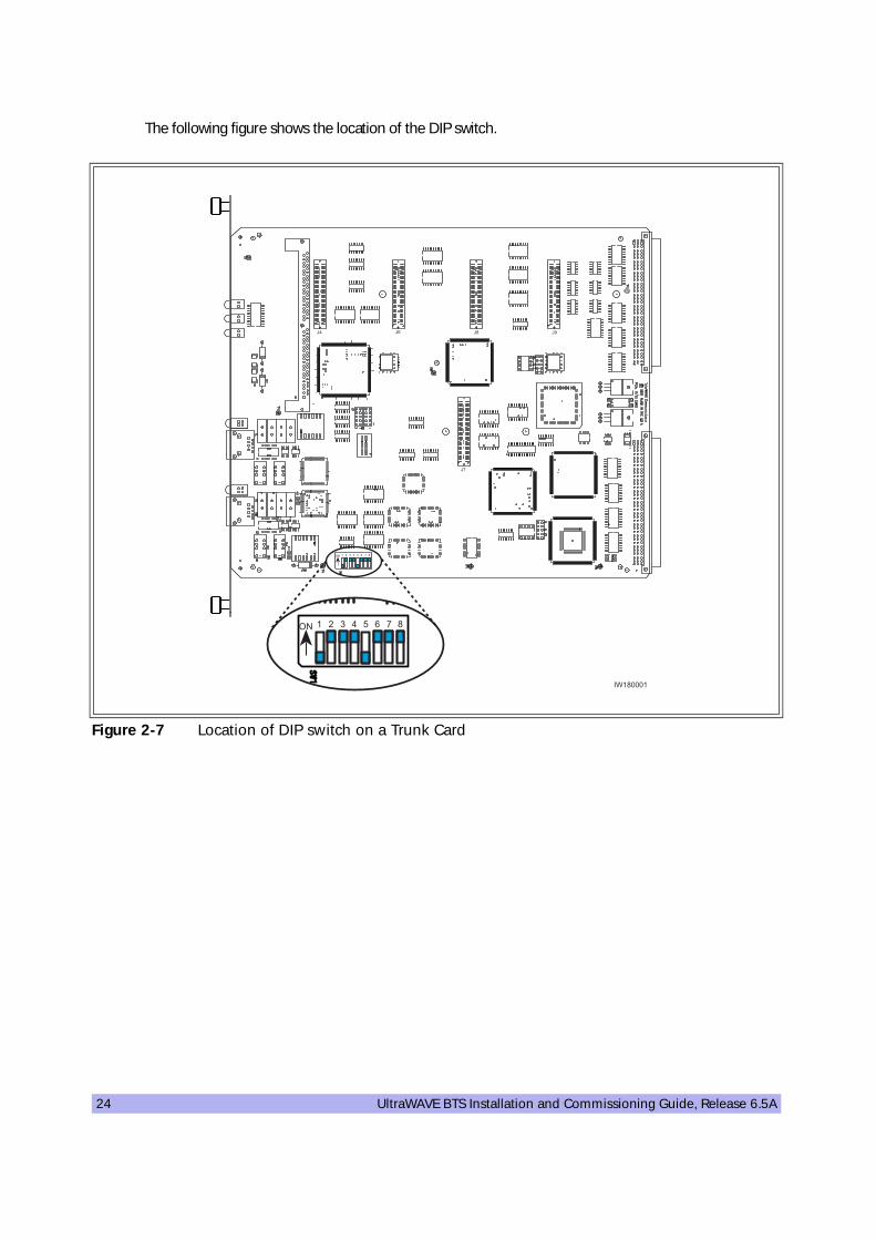
The following figure shows the location of the DIP switch.
Figure 2-7 Location of DIP switch on a Trunk Card
C2 C3
C�
"# � � 0� 1 2 � 3
C0 C>
"# � � 0� 1 2 � 3
���3����
Installation 25
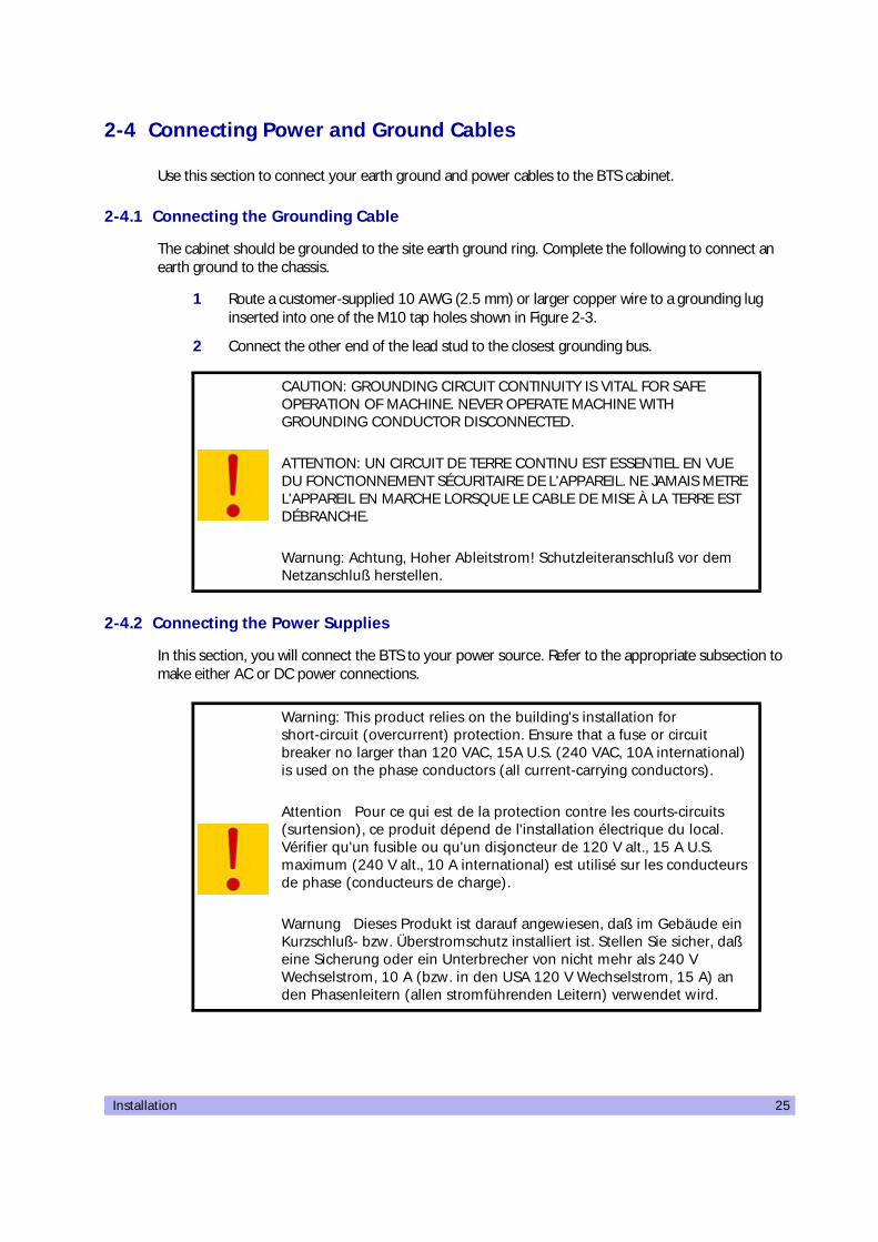
2-4 Connecting Power and Ground Cables
Use this section to connect your earth ground and power cables to the BTS cabinet.
2-4.1 Connecting the Grounding Cable
The cabinet should be grounded to the site earth ground ring. Complete the following to connect an earth ground to the chassis.
1 Route a customer-supplied 10 AWG (2.5 mm) or larger copper wire to a grounding lug inserted into one of the M10 tap holes shown in Figure 2-3.
2 Connect the other end of the lead stud to the closest grounding bus.
2-4.2 Connecting the Power Supplies
In this section, you will connect the BTS to your power source. Refer to the appropriate subsection to make either AC or DC power connections.
CAUTION: GROUNDING CIRCUIT CONTINUITY IS VITAL FOR SAFE OPERATION OF MACHINE. NEVER OPERATE MACHINE WITH GROUNDING CONDUCTOR DISCONNECTED.
ATTENTION: UN CIRCUIT DE TERRE CONTINU EST ESSENTIEL EN VUE DU FONCTIONNEMENT SÉCURITAIRE DE L'APPAREIL. NE JAMAIS METRE L'APPAREIL EN MARCHE LORSQUE LE CABLE DE MISE À LA TERRE EST DÉBRANCHE.
Warnung: Achtung, Hoher Ableitstrom! Schutzleiteranschluß vor dem Netzanschluß herstellen.
Warning: This product relies on the building's installation for short-circuit (overcurrent) protection. Ensure that a fuse or circuit breaker no larger than 120 VAC, 15A U.S. (240 VAC, 10A international) is used on the phase conductors (all current-carrying conductors).
Attention Pour ce qui est de la protection contre les courts-circuits (surtension), ce produit dépend de l'installation électrique du local. Vérifier qu'un fusible ou qu'un disjoncteur de 120 V alt., 15 A U.S. maximum (240 V alt., 10 A international) est utilisé sur les conducteurs de phase (conducteurs de charge).
Warnung Dieses Produkt ist darauf angewiesen, daß im Gebäude ein Kurzschluß- bzw. Überstromschutz installiert ist. Stellen Sie sicher, daß eine Sicherung oder ein Unterbrecher von nicht mehr als 240 V Wechselstrom, 10 A (bzw. in den USA 120 V Wechselstrom, 15 A) an den Phasenleitern (allen stromführenden Leitern) verwendet wird.

26 UltraWAVE BTS Installation and Commissioning Guide, Release 6.5A
AC Operation
The BTS is shipped from the factory with the internal cabling routed from the AC power supply subrack assembly to a molex connector on the top rear of the cabinet. A power supply cable is included with the BTS which should be used to connect to your AC power supply or battery backup system.
Make connections from the AC power supply to the cabinet as follows:
1 Verify the ground connection you made in Section 2-4.1 is secure.
2 Make sure that the power button located on all power supply modules is in the raised OFF position. See Figure 2-8 for the location of the power supply power buttons.
3 Plug the molex power connector into the power connection on the top of the cabinet. Secure the connector by twisting the connector sleeve until the lines on the cable connector and chassis connector align.
4 Plug the power cable into the electrical mains. Do not apply power to the chassis at this time. Wait until you are performing the off-line commissioning procedures in the next chapter.
Figure 2-8 Power Supply ON/OFF Buttons
CAUTION: THE POWER SUPPLY CORD IS USED AS THE MAIN DISCONNECT DEVICE, ENSURE THAT THE SOCKET-OUTLET IS LOCATED/INSTALLED NEAR THE EQUIPMENT AND IS EASILY ACCESSIBLE.
ATTENTION: LE CORDON D'ALIMENTATION EST UTILISÉ COMME INTERRUPTEUR GÉNÉRAL. LA PRISE DE COURANT DOIT ÊTRE SITUÉE OU INSTALLÉE À PROXIMITÉ DU MATÉRIEL ET ÊTRE FACILE D'ACCÉS.
Warnung: Das Netzkabel dient als Netzschalter. Stellen Sie sicher, das die Steckdose einfach zugänglich ist.
"#("��� �����
�#�.�
".��.�
�%.$�
"�� "#
�#�.�
".��.�
�%.$�
"�� "#
�#�.�
".��.�
�%.$�
"�� "#
����3���

Installation 27
-48 VDC Operation
The BTS is shipped from the factory with the internal cabling routed from the DC power supply subrack assembly to a molex connector on the top rear of the cabinet. A power supply cable is included with the BTS which should be used to connect to your DC power supply or battery backup system.
Use the following procedure:
1 Verify the ground connection you made in Section 2-4.1 is secure. The cabinet power supply is grounded through this connection. It is critical that this connection is made properly.
2 Make sure that the power button located on all power supply modules is in the raised OFF position. See Figure 2-8 for the location of the power supply power buttons.
3 Verify that the-48 VDC power source is off.
4 The -48 VDC power cable has two wires for the positive (+) connection and two wires for the negative (-) connection. This spreads the current draw across two pins of the molex connector for each connection.
Attach the two positive (+) cables to the positive side of your -48 VDC power source.
5 Attach the two negative (-) cables to the negative side of your -48 VDC power source.
6 Plug the molex power connector into the power connection on the top of the cabinet. Secure the connector by twisting the connector sleeve until the lines on the cable connector and chassis connector align.
The power main must be a Safe Extra-Low Voltage (SELV), -48 VDC supply as defined in IEC950 and EN60950.
Do not use the DC power supply circuit breaker to apply power to the chassis at this time. Wait until you are performing the off-line commissioning procedures in the next chapter.
CAUTION: THE POWER SUPPLY CORD IS USED AS THE MAIN DISCONNECT DEVICE, ENSURE THAT THE SOCKET-OUTLET IS LOCATED/INSTALLED NEAR THE EQUIPMENT AND IS EASILY ACCESSIBLE.
ATTENTION: LE CORDON D'ALIMENTATION EST UTILISÉ COMME INTERRUPTEUR GÉNÉRAL. LA PRISE DE COURANT DOIT ÊTRE SITUÉE OU INSTALLÉE À PROXIMITÉ DU MATÉRIEL ET ÊTRE FACILE D'ACCÉS.
Warnung: Das Netzkabel dient als Netzschalter. Stellen Sie sicher, das die Steckdose einfach zugänglich ist.
28 UltraWAVE BTS Installation and Commissioning Guide, Release 6.5A
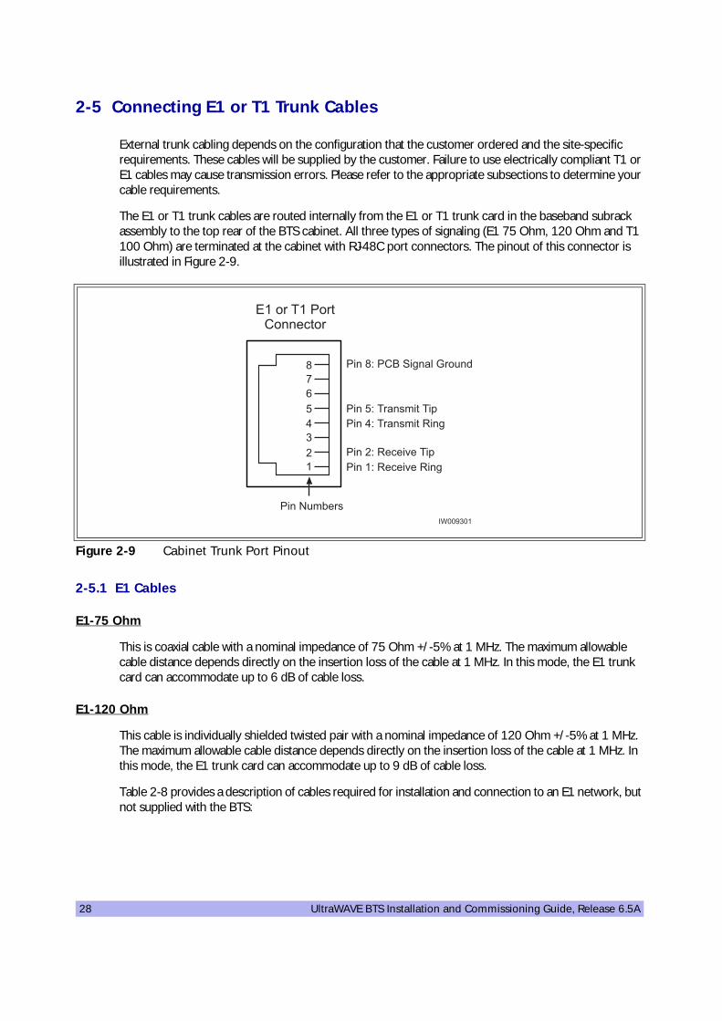
2-5 Connecting E1 or T1 Trunk Cables
External trunk cabling depends on the configuration that the customer ordered and the site-specific requirements. These cables will be supplied by the customer. Failure to use electrically compliant T1 or E1 cables may cause transmission errors. Please refer to the appropriate subsections to determine your cable requirements.
The E1 or T1 trunk cables are routed internally from the E1 or T1 trunk card in the baseband subrack assembly to the top rear of the BTS cabinet. All three types of signaling (E1 75 Ohm, 120 Ohm and T1 100 Ohm) are terminated at the cabinet with RJ-48C port connectors. The pinout of this connector is illustrated in Figure 2-9.
2-5.1 E1 Cables
E1-75 Ohm
This is coaxial cable with a nominal impedance of 75 Ohm +/-5% at 1 MHz. The maximum allowable cable distance depends directly on the insertion loss of the cable at 1 MHz. In this mode, the E1 trunk card can accommodate up to 6 dB of cable loss.
E1-120 Ohm
This cable is individually shielded twisted pair with a nominal impedance of 120 Ohm +/-5% at 1 MHz. The maximum allowable cable distance depends directly on the insertion loss of the cable at 1 MHz. In this mode, the E1 trunk card can accommodate up to 9 dB of cable loss.
Table 2-8 provides a description of cables required for installation and connection to an E1 network, but not supplied with the BTS:
Figure 2-9 Cabinet Trunk Port Pinout
���012
3�
�4��D����4:��4��4��D����4:��4�B
����>���
�4�# !���
�4�3D���'4B���F�� ��
�������������������
�4�0D�����4��4�B�4�1D�����4��4�
Installation 29
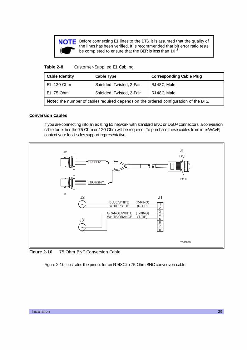
Conversion Cables
If you are connecting into an existing E1 network with standard BNC or DSUP connectors, a conversion cable for either the 75 Ohm or 120 Ohm will be required. To purchase these cables from interWAVE, contact your local sales support representative.
Figure 2-10 illustrates the pinout for an RJ-48C to 75 Ohm BNC conversion cable.
Before connecting E1 lines to the BTS, it is assumed that the quality of the lines has been verified. It is recommended that bit error ratio tests be completed to ensure that the BER is less than 10-8.
Table 2-8 Customer-Supplied E1 Cabling
Cable Identity Cable Type Corresponding Cable Plug
E1, 120 Ohm Shielded, Twisted, 2-Pair RJ-48C, Male
E1, 75 Ohm Shielded, Twisted, 2-Pair RJ-48C, Male
Note: The number of cables required depends on the ordered configuration of the BTS.
Figure 2-10 75 Ohm BNC Conversion Cable
����>���
3
"�%#F�(�)���
�$.�(�)���
�)���("�%#F�
�)���(�$.� 5�+���65�+��#F6
5�+���65�+��#F6
���
12�
0
C�
C�
C�
C�
C�
�����/�
��%#'&��
�4��
�4�3
C�

30 UltraWAVE BTS Installation and Commissioning Guide, Release 6.5A
Figure 2-11 illustrates the pinout for the RJ-48C to DSUB 120 Ohm conversion cable.
2-5.2 T1 Cables
T1-100 Ohm
For T1 connections, the proper cable is individually shielded twisted pair with a nominal impedance of 100 Ohm +/-5% at 772 kHz. The maximum allowable cable distance depends directly on the insertion loss of the cable at 772 kHz. The T1 card can accommodate up to 9 dB of cable loss. When using 22 AWG ABAM cable, 9 dB of loss is approximately 2000 feet. When using Belden type 9729 (with a cable loss of 6 dB per 1000 feet at 772 kHz) the maximum cable distance is approximately 1500 feet.
Table 2-9 provides a description of cables required for installation and connection to a T1 network, but not supplied with the BTS:
Figure 2-11 120 Ohm DSUB Conversion Cable
Before connecting T1 lines to the BTS, it is assumed that the quality of the lines has been verified. It is recommended that bit error rate tests be completed to ensure that the BER is less than 10-8.
Table 2-9 Customer-Supplied T1 Cabling
Cable Identity Cable Type Corresponding Cable Plug
T1, 100 Ohm Shielded, Twisted, 2-Pair RJ-48C, Male
Note: The number of cables required depends on the ordered configuration of the BTS.
���
�>
����>���
3
"�%#F�(�)���
�$.�(�)���
�)���("�%#F�
�)���(�$.� 5�+���65�+��#F6
5�+���65�+��#F6
���
12�
0
C� C�
�4�>
C�
C�
�4��
�4��1 �4�3
�4��
�4�3

Installation 31
2-5.3 Connecting E1 or T1 Lines
All E1 or T1 cable routing should be installed per the site survey documentation in conjunction with the information identified in the interWAVE Network Implementation Manual.
• Using the appropriate customer-supplied cables, connect the Abis interface E1 and/or T1 cables to the local E1 or T1 provider.
2-5.4 Direct Cabling Between Multiple UltraWAVE or WAVEXpress Systems
This section provides information for cabling between WAVEXpress equipment. The external cabling between your equipment will vary depending on the configuration of the cable management assembly of each chassis. This could consist of any combination of BNC, DSUB or RJ-48C connectors and either E1 or T1 signaling.
Using Cross-Over RJ-48C Cables
When connecting a shielded twisted pair crossover cable between two UltraWAVE or WAVEXpress systems, the routing of the pins needs to comply with the cable mapping shown in Figure 2-12. The RJ-48C cable connector may be of the conventional plastic body type with the shield and drain wires of the cable connected to a pigtail to pin 8 (Signal Ground), which is internally grounded to the card. However, a shielded cable plug may also be used, terminating the cable shield to an integral metal shell of the RJ-48 jack which then makes an electrical connection to the front panel when installed. Figure 2-12 provides the pin assignments for the RJ-48C jacks.
The direct cabling between systems requires crossover cables (Tx to Rx, and Rx to Tx), instead of the straight-through cabling used when connecting systems through a radio or telephone provider network.
Figure 2-12 Cable Mapping of RJ-48C Crossover Cable
���012
3�
���012
3�
�4��D����4:��4�
�4�1D�����4��4�
�4��D����4:��4�B
�4�0D�����4��4�B
�4��D����4:��4�B�4��D����4:��4�
����0>��
�4�# !���
���'4B���F�� ��
�������������������
�4�0D�����4��4�B�4�1D�����4��4�
�������������������

32 UltraWAVE BTS Installation and Commissioning Guide, Release 6.5A
To connect two systems using RJ-48C cables, connect a crossover cable (see Figure 2-12) from the port 1 of the first chassis to port 0 of the second chassis.
2-5.5 Cabling External BTSs
The BTS can also be connected to daisy-chained BTSs as described in Section 2-5.4. These daisy-chained BTSs will download their operating software from the BSC into their flash memory upon reboot. Some additional software configuration is also required to setup the operations and maintenance link to the OMC. This additional configuration of the OAM timeslots is required for daisy-chained BTSs as discussed in Chapter Four.
2-6 Connecting Antennas
The cabinet assembly provides external access to the male N-type connectors for your external antennas. Your antenna cable should terminate with a 90° N-type female connector or an N-type female to male elbow adapter may be used for a more convenient connection to the cabinet. Insertion loss for the elbow type of connector is typically between 0.1 and 0.2 dBm.
The antenna cabling for the BTS can be configured in several ways depending on a number of factors including the number of TRXs, number of antennas and use of diversity. Your site specific configuration was determined during the network planning stage of implementation.
In the subsequent sections, each RF configuration is detailed from the RF module connector to the internal RF connector. Figure 2-13 the relationship between the three connectors. The RF modules are connected to the internal RF connectors at the factory and are pre-configured for your BTS configuration.
Table 2-10 Customer-Supplied Adapters and Cabling
Identity Cable Type Corresponding Cable Plug
Antenna cable (external) Coaxial N-type, Female
Adapter (optional) 90 degree elbow N-type Female to N-type Male
Note: The number of cables required depends on the ordered configuration of the BTS.
Figure 2-13 Antenna Cabling for Standard BTS Configurations
��������������������5�4�=����� !��6
��&�� ������������
�;������������������5����<��!4���6
%#�*�/
%#�&%�#
���
�$�
"#$�#�
"#
"��
���
���
���
��0
���
���
���
��0
%#�*�/
%#�&%�#
���
�$�
"#$�#�
"#
"��
���
���
���
��0
���
���
���
��0
%#�*�/
%#�&%�#
���
�$�
"#$�#�
"#
"��
���
���
���
��0
���
���
���
��0
� � � � 10
����>��0

Installation 33
You will attach an elbow connector and your antenna cable to the external RF connector associated with the internal RF connector shown in the appropriate figure.
The subsequent sections identify the cable routing for the different BTS antenna configurations that you identified in Chapter One. You must install the antennas such that the general population is kept at least 164-inches from the main beam of the antenna. For more information of RF radiation properties of the UltraWAVE, refer to Section 2-6.17.
Proceed to the appropriate subsection to connect your site-specific antenna cable configuration.
2-6.1 Omni 1 TRX (O1) Configuration
This is a 50 watt (47 dBm) two antenna configuration available in either 850 MHz or 900 MHz frequencies. Connect your antennas as shown in Figure 2-14.
All RF cabling must be completed with the chassis powered off and, preferably, with the power cable disconnected from the cabinet. Do not disconnect RF coaxial connectors on the interWAVE equipment or antenna systems while the radio equipment is operating. Never place any body part over or look into any RF connector while the radio equipment is transmitting.Radio frequency signal levels that give rise to hazardous radiation levels can exist within the transmitter, power amplifiers, associated RF multiplexers and antenna systems.
Figure 2-14 Antenna Cabling for O1 Configuration
���� �������>��1
%#�*�/
%#�&%�#
�������������������
�;�����������������
%�������*4:���4�
%�������������4��
� � � 0 1�
#��.���#��.��� #��.��� #��.���
%�������&�4�

34 UltraWAVE BTS Installation and Commissioning Guide, Release 6.5A
2-6.2 Omni 2 TRX (O2) Configuration
This is a 50 watt (47 dBm) two antenna configuration available in either 850 MHz or 900 MHz frequencies. Connect your antennas as shown in Figure 2-15.
2-6.3 Omni 3 TRX (O3) Configuration
This is a 25 watt (44 dBm) two antenna configuration available in either 850 MHz or 900 MHz frequencies. Connect your antennas as shown in Figure 2-16.
2-6.4 Omni 4 TRX (O4) Configuration
This is a 25 watt (44 dBm) two antenna configuration available in either 850 MHz or 900 MHz frequencies.
Figure 2-15 Antenna Cabling for O2 Configuration
Figure 2-16 Antenna Cabling for O3 Configuration
���� �������>��1
%#�*�/
%#�&%�#
�������������������
�;�����������������
%�������*4:���4�
%�������������4��
� � � 0 1�
#��.���#��.��� #��.��� #��.���
%�������&�4�
%#�
���� �������>��2
�������������������
�;�����������������
%�������*4:���4�
%�������������4��
� � � 0 1�
#��.���#��.��� #��.��� #��.���
%�������&�4�
%#�

Installation 35
• Connect your antennas as shown in Figure 2-17.
2-6.5 Omni 5 TRX (O5) Configuration
This is a 15 watt (42 dBm) two antenna configuration available in either 850 MHz or 900 MHz frequencies.
• Connect your antennas as shown in Figure 2-18.
Figure 2-17 Antenna Cabling for O4 Configuration
Figure 2-18 Antenna Cabling for O5 Configuration
%#�
���� �������>��2
�������������������
�;�����������������
%�������*4:���4�
%�������������4��
� � � 0 1�
#��.���#��.��� #��.��� #��.���
%�������&�4�
%#�
%#�
���� �������>��2
�������������������
�;�����������������
%�������*4:���4�
%�������������4��
� � � 0 1�
#��.���#��.��� #��.��� #��.���
%�������&�4�
%#�

36 UltraWAVE BTS Installation and Commissioning Guide, Release 6.5A
2-6.6 Omni 6 TRX (O6) Configuration
This is a 15 watt (42 dBm) two antenna configuration available in either 850 MHz or 900 MHz frequencies.
• Connect your antennas as shown in Figure 2-19.
2-6.7 Omni 5 (05) and Omni 6 (O6) 25 Watt Configuration
These are a 25 watt (44 dBm) three antenna configurations available in either 850 MHz or 900 MHz frequencies.
• Connect your antennas as shown in Figure 2-20.
Figure 2-19 Antenna Cabling for O6 Configuration
Figure 2-20 Antenna Cabling for O5 and O6 25W Configuration
%#�
���� �������>��2
�������������������
�;�����������������
%�������*4:���4�
%�������������4��
� � � 0 1�
#��.���#��.��� #��.��� #��.���
%�������&�4�
%#�
%#�
���� �������>���
�������������������
�;�����������������
%�������*4:���4�
%�������������4��
� � � 0 1�
#��.��� #��.��� #��.���
%�������&�4�
%#� %#�
%�������&�4�
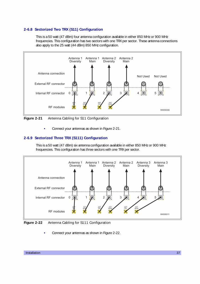
Installation 37
2-6.8 Sectorized Two TRX (S11) Configuration
This is a 50 watt (47 dBm) four antenna configuration available in either 850 MHz or 900 MHz frequencies. This configuration has two sectors with one TRX per sector. These antenna connections also apply to the 25 watt (44 dBm) 850 MHz configuration.
• Connect your antennas as shown in Figure 2-21.
2-6.9 Sectorized Three TRX (S111) Configuration
This is a 50 watt (47 dBm) six antenna configuration available in either 850 MHz or 900 MHz frequencies. This configuration has three sectors with one TRX per sector.
• Connect your antennas as shown in Figure 2-22.
Figure 2-21 Antenna Cabling for S11 Configuration
Figure 2-22 Antenna Cabling for S111 Configuration
%#�*�/
%#�&%�#
%#�*�/
%#�&%�#
���� �������>��3
�������������������
�;�����������������
%�������*4:���4�
%�������������4��
� � � 0 1�
#��.��� #��.���
%�������&�4�
%�������&�4�
%�������*4:���4�
%#�*�/
%#�&%�#
%#�*�/
%#�&%�#
���� �������>���
�������������������
�;�����������������
%�������*4:���4�
%�������������4��
� � � 0 1�
%�������&�4�
%�������&�4�
%�������*4:���4�
%#�*�/
%#�&%�#
%�������&�4�
%�������*4:���4�

38 UltraWAVE BTS Installation and Commissioning Guide, Release 6.5A
2-6.10 Two Sector Four TRX (S22) Configuration
This is a 50 watt (47 dBm) four antenna configuration available in either 850 MHz or 900 MHz frequencies. This configuration has two sectors with two TRXs per sector. These antenna connections also apply to the 25 watt (44 dBm) 900 MHz configuration.
• Connect your antennas as shown in Figure 2-23.
2-6.11 Three Sector Four TRX (S211) Configuration
This is a 50 watt (47 dBm) six antenna configuration available in either 850 MHz or 900 MHz frequencies. This configuration has three sectors with two TRXs in one sector and one TRX in the other two sectors. These antenna connections also apply to the 25 watt (44 dBm) 900 MHz configuration.
• Connect your antennas as shown in Figure 2-24.
Figure 2-23 Antenna Cabling for S22 Configuration
Figure 2-24 Antenna Cabling for S211 Configuration
%#�*�/
%#�&%�#
%#�*�/
%#�&%�#
���� �������>��3
�������������������
�;�����������������
%�������*4:���4�
%�������������4��
� � � 0 1�
#��.��� #��.���
%�������&�4�
%�������&�4�
%�������*4:���4�
%#�*�/
%#�&%�#
%#�*�/
%#�&%�#
���� �������>���
�������������������
�;�����������������
%�������*4:���4�
%�������������4��
� � � 0 1�
%�������&�4�
%�������&�4�
%�������*4:���4�
%#�*�/
%#�&%�#
%�������&�4�
%�������*4:���4�

Installation 39
2-6.12 Three Sector Five TRX (S221) Configuration
This is a 50 watt (47 dBm) six antenna configuration available in either 850 MHz or 900 MHz frequencies. This configuration has three sectors with two TRXs in two sectors and one TRX in the last sector.
• Connect your antennas as shown in Figure 2-25.
2-6.13 Three Sector Six TRX (S222) Configuration
This is a 50 watt (47 dBm) six antenna configuration available in either 850 MHz or 900 MHz frequencies. This configuration has three sectors with two TRXs in each sector. These antenna connections also apply to the 25 watt (44 dBm) 900 MHz configuration.
• Connect your antennas as shown in Figure 2-26.
Figure 2-25 Antenna Cabling for S221 Configuration
Figure 2-26 Antenna Cabling for S222 Configuration
%#�*�/
%#�&%�#
%#�*�/
%#�&%�#
���� �������>���
�������������������
�;�����������������
%�������*4:���4�
%�������������4��
� � � 0 1�
%�������&�4�
%�������&�4�
%�������*4:���4�
%#�*�/
%#�&%�#
%�������&�4�
%�������*4:���4�
%#�*�/
%#�&%�#
%#�*�/
%#�&%�#
���� �������>���
�������������������
�;�����������������
%�������*4:���4�
%�������������4��
� � � 0 1�
%�������&�4�
%�������&�4�
%�������*4:���4�
%#�*�/
%#�&%�#
%�������&�4�
%�������*4:���4�

40 UltraWAVE BTS Installation and Commissioning Guide, Release 6.5A
2-6.14 Two Sector Five TRX (S32) Configuration
This is a 25 watt (44 dBm) four antenna configuration available in either 850 MHz or 900 MHz frequencies. This configuration has one sector with three TRXs in one sector and two TRXs in the other sector.
• Connect your antennas as shown in Figure 2-27.
2-6.15 Two Sector Six TRX (S33) Configuration
This is a 25 watt (44 dBm) four antenna configuration available in either 850 MHz or 900 MHz frequencies. This configuration has two sectors with three TRXs per sector.
• Connect your antennas as shown in Figure 2-28.
Figure 2-27 Antenna Cabling for S32 Configuration
Figure 2-28 Antenna Cabling for S33 Configuration
%#� %#� %#�*�/
%#�&%�#
���� �������>��>
�������������������
�;�����������������
%�������*4:���4�
%�������������4��
� � � 0 1�
#��.��� #��.���
%�������&�4�
%�������&�4�
%�������*4:���4�
%#� %#�%#� %#�
���� �������>���
�������������������
�;�����������������
%�������*4:���4�
%�������������4��
� � � 0 1�
#��.��� #��.���
%�������&�4�
%�������&�4�
%�������*4:���4�

Installation 41
2-6.16 Two Sector Six TRX (S42) Configuration
This is a 25 watt (44 dBm) four antenna configuration available in either 850 MHz or 900 MHz frequencies. This configuration has two sectors with four TRXs in one sector and two TRXs in the other sector.
• Connect your antennas as shown in Figure 2-29.
2-6.17 RF Radiation Hazard
As of October 15, 1997, all products must address the issue of Human Exposure to RF electromagnetic fields. Referring to OET Bulletin 65, RF radiation limits for the 300 - 1500 MHz range are f / 300 mW/cm2 for occupational exposure, and f / 1500 mW/cm2 for general population exposure (where f is frequency in MHz). At the 869 MHz cellular band these limits are 2.90 mW/cm2 for occupational exposure, and 0.58 mW/cm2 for general population exposure.
The Ultrawave base station may consist of up to six separate transceivers, with each of the transmitters operating at a maximum output power of +47 dBm (50W). The Ultrawave base station transmitters operate in the U.S. cellular band of 869 to 894 MHz.
As the Ultrawave is intended to be operated in cellular service, each of its transmitters is typically connected to a 65 - 120 degree sector antenna or omni directional antenna. For the purpose of the MPE calculations, it will be assumed that the Ultrawave is fully equipped with six transceivers, and that two different transmitters are used in each 120 degree sector. For the MPE calculations this would be the worst case radiation levels as the equivalent RF power of +50 dBm (100W) would be transmitted into a 120 degree sector.
The typical gain of 65 - 120 degree sector antenna is in the range of +6 to +18 dBi. However, there is the highest ERP limitation on the Part22 requirement which is 500W(57 dBd).
The duty cycle of the transmitter is 100%. Assuming two transmitters are operating into the same 120 degree sector, a maximum of +47 dBm of RF energy would be transmitted into two antennas, with total EIRP=61 dBi would be the worst case.
Figure 2-29 Antenna Cabling for S42 Configuration
%#� %#� %#�*�/
%#�&%�#
���� �������>��>
�������������������
�;�����������������
%�������*4:���4�
%�������������4��
� � � 0 1�
#��.��� #��.���
%�������&�4�
%�������&�4�
%�������*4:���4�

42 UltraWAVE BTS Installation and Commissioning Guide, Release 6.5A
RF power density can be calculated with the equation: S = P * G / 4p R2, where S = power density in mW/cm, P = power input to the antenna in mW, G = power gain of the antenna, and R = distance to the center of radiation of the antenna in cm. By rearranging this equation, the relationship between distance (R) and Power Density (S) can be found.
Rearranging R =Ö(PG / 4p S), and solving for the maximum limits of 2.90 mW/ cm 2, and 0.58 mW/ cm 2 we have:
R(2.90 mW/cm2) = Ö 1,260,000 mW / 4p * 2.90 = 186 cm, or 73 inches.
R(0.58 mW/cm2) = Ö 1,260,000 mW / 4p * 0.58 = 416 cm, or 164 inches.
These results show that the general population RF exposure limits are not exceeded as long as the general population is kept 164-inches from the feed point of the antenna.
The propagation characteristics at 870 MHz dictate a line-of-sight type of RF path. As such, typical installation locations are up on rooftops or masts to get above ground level path obstructions. When the Ultrawave antennas are installed in this manner, the general population will be further than 164-inches from the antenna, and RF exposure limits will be met.
1,26,000 mW is used to account for two 50,000 mW transmitters operating into each 120 degree sector.

Installation 43
2-7 Connecting External Alarms
The WAVEView OMC supports many alarms from the BTS. The external alarms are reflected at the OMC operator station, and may be used for site alarms, such as open door, temperature and battery back-up alarms. These customer defined alarms are sampled every two minutes by default and will report an alarm when sent by the BTS alarm controller.
Using the details provided in these sections, make your connections for external alarm inputs.
The OMC operator can set the alarm text as described in the WAVEView OMC Setup and System Administration Guide.
Identifying the Terminal Block
The alarms are processed on the alarm interface module located on the rear of the RF subrack assembly. The alarm interface module has connections for incoming signals from external alarms and the power supplies and an outgoing connection to the ICP processor card through a USB type cable. The interfaces are shown in Figure 2-30.
This terminal block provides a plug connection for up to seventeen external alarms. The plugs, supplied with the BTS, provide a closed loop for connection to a normally open alarm mechanism. The plug
If you are replacing an existing WAVEXpress system which has external alarms connected directly to the processor card, you may connect your existing RJ-45 alarm cable directly into the ICP processor card alarm connector. Optionally, you can re-route your existing alarms to the UltraWAVE alarm terminal block or add additional external alarms.
Figure 2-30 Alarm Interface Module
��� ��� ��� ��0 ��1 ��2 ��� ��3 ��> ���� ���� ���� ���� ���0 ���1 ���2
���� ���3 ���> ����
������ ��� 4����<���
�������������4����<���
�;����������4����<���
��������

44 UltraWAVE BTS Installation and Commissioning Guide, Release 6.5A
identifiers correspond to the alarm code sent to the OMC. See Table 2-11 for Terminal Block pin assignments, and see Figure 2-31 for external alarm connection details.
To connect the external alarm contacts to the external alarm terminal block:
Figure 2-31 Customer-Defined External Alarm Connections
Table 2-11 External Alarm Terminal Block Pin Assignment
Plug Identifier Alarm Code Major Alarm Type
EP1 2326 Customer definable UltraWAVE External Alarm 1
EP2 2327 Customer definable UltraWAVE External Alarm 2
EP3 2328 Customer definable UltraWAVE External Alarm 3
EP4 2329 Customer definable UltraWAVE External Alarm 4
EP5 2330 Customer definable UltraWAVE External Alarm 5
EP6 2331 Customer definable UltraWAVE External Alarm 6
EP7 2332 Customer definable UltraWAVE External Alarm 7
EP8 2333 Customer definable UltraWAVE External Alarm 8
EP9 2334 Customer definable UltraWAVE External Alarm 9
EP10 2335 Customer definable UltraWAVE External Alarm 10
EP11 2336 Customer definable UltraWAVE External Alarm 11
EP12 2337 Customer definable UltraWAVE External Alarm 12
EP13 2338 Customer definable UltraWAVE External Alarm 13
EP14 2339 Customer definable UltraWAVE External Alarm 14
EP15 2340 Customer definable UltraWAVE External Alarm 15
EP16 2341 Customer definable UltraWAVE External Alarm 16
EP17 2342 Customer definable UltraWAVE External Alarm 17
��� ��� ��� ��0 ��1 ��2 ��� ��3 ��> ���� ���� ���� ���� ���0 ���1 ���2
���� ���3 ���> ����
�� B4����4<4��
��������
�4��5�4B���6
�4��5B�� ��6

Installation 45
1 Route the external alarm input cables from the external equipment through the cable gland on the CMA to the external alarm terminal block.
2 Using the details provided in Figure 2-32, connect the normally-open alarm inputs from the external equipment to the external alarm plug.
3 Connect the alarm plug to the terminal block. Note the plug identifier and using Table 2-11 inform the OMC operator which alarm code corresponds to the external alarm that you have just installed.
Figure 2-32 External Alarm Plug
Inputs from external alarms should be normally open. When the external contacts close, the BTS sends an alarm to the OMC.
��������
�4��5�4B���6
�4��5B�� ��6
46 UltraWAVE BTS Installation and Commissioning Guide, Release 6.5A
2-8 Post Installation Cabling and Checks
Connecting the Chassis
Before commissioning the equipment, make sure that:
• The Abis interface E1 and/or T1 cables are routed to the telephone provider
• The DIP switch settings on the E1 or T1 trunk cards are set correctly and if you are using the 75 Ohm E1 trunk card that the ground jumper is in the correct position (refer to Section 2-3 for E1 and/or T1 DIP switch settings)
• The cabinet power is turned off
• Antenna cables are connected to RF antenna port connectors as appropriate
Verifying External Cabling
• It is the operator's responsibility to verify that all inter-chassis E1 and/or T1 links are ordered, installed and certified by the telephone provider according to ANSI T1.403 specifi-cations before on-line commissioning is performed
• The operator should also perform end-to-end bit error ratio or bit error rate tests over a 20-minute period on the E1 and T1 Abis interface link(s), and verify that the BER is 10-8 or better

Off-Line Commissioning 47
ThreeOff-Line Commissioning
30000
The off-line commissioning process includes the following steps:
• Pre off-line commissioning, where you ensure that the system is in an appropriate state. This includes:
• visual inspection
• compliance checks
• Startup Verification, where you verify that the system comes up correctly by observing the LEDs on the front panel
• Craft PC tests, where you use the Craft PC to verify the software configuration and run tests.
• Post off-line commissioning, where you prepare the system for online commissioning.
The rest of this chapter includes the detailed instructions for these steps.
Under normal operating conditions, interWAVE Communications radio equipment complies with the limits for human exposure to radio frequency (RF) fields adopted by the Federal Communications Commission (FCC). All interWAVE Communications, Inc. radio equipment is designed so that under normal working conditions radio frequency radiation directly from the radio is negligible when compared with the permissible limit of continuous daily exposure recommended in the United States of America by ANSI/IEEE C95.1-19991 (R1997), Safety Levels with Respect to Human Exposure to Radio Frequency Electromagnetic Fields, 3 kHz to 300 GHz.
Radio frequency signal levels that give rise to hazardous radiation levels can exist within the transmitter, power amplifiers, associated RF multiplexers and antenna systems.
Do not disconnect RF coaxial connectors on the interWAVE equipment or antenna systems while the radio equipment is operating. Never place any body part over or look into any RF connector while the radio equipment is transmitting.

48 UltraWAVE BTS Installation and Commissioning Guide, Release 6.5A
3-1 Pre Off-Line Commissioning
The following sections must be completed before doing the off-line commissioning. The off-line commissioning of the BTS must take place on-site after installation. It is critical that all RF connections have been completed before proceeding with the off-line commissioning.
3-1.1 Visual Inspection
Complete the following inspections to ensure that the system is ready for off-line commissioning:
On-Site Visual Inspection
If you are doing your visual inspection on-site, check that:
• The cabinet has been securely installed at the appropriate site.
• The cabinet power supplies to the cabinet are OFF.
• The cabinet is connected to a suitable power source.
• The cabinet is correctly grounded.
• All cables are available and secured in their correct positions.
• All cards and modules are correctly seated and populated according to the original purchase order.
• E1 or T1 transmission cables are available and labeled.
• RF transmission cables are connected to antennas.
Compliance and Power Checks
• Cross-check with the site specific data to ensure that the BTS is correctly configured with all cards and modules.
• Ensure that you have access to Checklist 2 and that all serial numbers of all cards are listed there. This should have been completed in Chapter One.
• Verify that any test equipment to be used has a current calibration certificate.
The BSS software used in the BTS is highly complex. Before proceeding, contact Customer Service to verify that you have the latest available software. You must have the correct software CD-ROM and know the current patch level for your software version before commissioning the BTS. Contact your Level 2 support representative for additional assistance.
The off-line commissioning steps are listed in Checklist 3.

Off-Line Commissioning 49
• Verify that the voltage for the installation site match those of the chassis power supply modules (either 230 VAC, 115 VAC, or -48 VDC, as specified on the power supply subrack assembly).
Label and Disconnect Cables
1 Verify that all E1 and/or T1 cables connected to the chassis are properly labeled.
2 Disconnect all E1 and/or T1 cables from the top of the cabinet if there are any cables connected.

50 UltraWAVE BTS Installation and Commissioning Guide, Release 6.5A
3-2 Off-Line Commissioning the UltraWAVE BTS
The verification procedures for off-line commissioning are run on the processor card in the BTS. Locate the processor card in the baseband subrack assembly as shown in
3-2.1 Connecting the Craft PC to the ICP Processor Card
You will be making two connections from the Craft PC to the ICP processor card.The first is a slow-speed serial connection used for checking the software version installed on the card, verifying boot parameters and monitoring test results. The second is a faster Ethernet connection used for opening telnet sessions with the ICP. Telnet sessions are required for downloading software to the ICP. The serial and ethernet connections are both required to configure and test the BTS.
Required Hardware
The following hardware is required to connect the Craft PC to the ICP processor card through an ethernet and serial connection. Note that this hardware is supplied with the Craft PC:
• one 3Com 3C589D PCMCIA Ethernet card with a 100/10-Base-2 combo transceiver
• one 3 meter standard RJ-11 patch cable
• one 3 meter standard Ethernet crossover cable
• one grey RJ-11 to DB9 adapter, part number 180247
Figure 3-1 BTS Processor Card
The following section describes procedures performed using the Craft PC. For more information pertaining to the use of the Craft PC, please refer to the interWAVE Craft PC Guide.
�������������
��������
"#$�#�
�$�
���
�"���
� �
�"���
� �%$%�&'
%$%�&'
��������������������������(#������
�������������������������'(#������
���")&
"#$�#����
�$�
'�#
�"#
�#��
��������������������������(#������
�������������������������'(#������
���
*���#
"#$�#�
�$�
��+�
��+%
��&),�$-
��".�
���
*���#
"#$�#�
�$�
��+�
��+%
��&),�$-
��".�
���
*���#
"#$�#�
�$�
��+�
��+%
��&),�$-
��".�
���
*���#
"#$�#�
�$�
��+�
��+%
��&),�$-
��".�
���
*���#
"#$�#�
�$�
��+�
��+%
��&),�$-
��".�
���
*���#
"#$�#�
�$�
��+�
��+%
��&),�$-
��".�
� � � � 0 1 2 � 3

Off-Line Commissioning 51
Setting Up a Serial Connection via the ICP Processor Card Serial Port
1 Connect the RJ-11 patch cable to ICP processor card connector labeled ‘CON’.
2 Connect the opposite end of the patch cable to the RJ-11 to DB9 adapter and connect the DB9 adapter to the serial port on the back of the Craft PC, as shown in the following figure.
The following figure shows a physical serial port connection between the Craft PC and the ICP processor card:
Setting Up an Ethernet Connection via the ICP Processor Card Ethernet Port
1 Connect the Ethernet crossover cable to the ICP processor card Ethernet port labeled “ENET”.
2 Connect the other end of the cable to the Ethernet transceiver.
3 Insert the transceiver firmly into the PCMCIA card slot on the side of the Craft PC.
Figure 3-2 Connecting to the Craft PC via the ICP Serial Port
���31���
"#($�#�
�"���
� �
�"���
� �
%$%�&'
�$�
���
%$%�&'
���<������ ���
'��4������
�C+������=��!��
�C+����*�+>%������
��������������������������(#������
"#$�#����
�$�'�#
�'�
�"#
�#��
�������������������������'(#������

52 UltraWAVE BTS Installation and Commissioning Guide, Release 6.5A
The following figure shows a physical ethernet port connection between the Craft PC and the ICP processor card:
C
3-2.2 Starting XWindows Using the Craft PC
In this chapter, you will use the Craft PC to verify the software configuration and other aspects of the BSC operation. This section describes how to start the Craft PC and the Windows environment while subsequent sections will provide connection, test and verification procedures. For information regarding the Linux based Craft PC, see the interWAVE Craft PC Guide.
Starting XWindows from Windows NT/2000/XP
1 With your left mouse button, double click the Craft PC icon on the desktop.
2 If you get an error message, or if the XWindows environment does not allow you to create new XWindows, stop the CPC environment by pressing [ALT-F4] and restart the environment.
The XWindows environment now starts.
Figure 3-3 Connection to the Craft PC via the ICP Ethernet Port
The following sections describe procedures performed using the Craft PC. For more information pertaining to the use of the Craft PC, please refer to the interWAVE Craft PC Guide. Note that all commands in bold are those entered by the user.
���31���
��=���������
�C+01��=�����������:����!��
��=������������4:��
��&��%��������
���<���
"#($�#�
�"���
� �
�"���
� �
%$%�&'
�$�
���
%$%�&'
��������������������������(#������
"#$�#����
�$�'�#
�'�
�"#
�#��
�������������������������'(#������

Off-Line Commissioning 53
3-2.3 Power-On LED Tests
This section describes how to power-on the BTS and verify that the cards in the system come up properly by viewing the LEDs on the front panel. The purpose of these tests is to verify that the LEDs come up in the correct state, indicating that the system is operating normally.
When you power-on the BTS, it automatically runs its power on self tests (POST), downloads software to the TRX cards, then attempts to bring up the cards. While it is bringing up the cards and when it is finished, the LEDs indicate the state of the each card.
Use the following procedure:
1 Power on the BTS by depressing the power buttons illustrated in Figure 2-8.
2 Verify that the front-panel LEDs flash in the sequence shown in the following figure:
Figure 3-4 LED Locations
The POST tests will be used later. You can ignore them for now.
��������
"#$�#�
�$�
���
�"���
� �
�"���
� �%$%�&'
%$%�&'
��������������������������(#������
�������������������������'(#������
���")&
"#$�#����
�$�
'�#
�"#
�#��
��������������������������(#������
�������������������������'(#������
���
*���#
"#$�#�
�$�
��+�
��+%
��&),�$-
��".�
���
*���#
"#$�#�
�$�
��+�
��+%
��&),�$-
��".�
���
*���#
"#$�#�
�$�
��+�
��+%
��&),�$-
��".�
���
*���#
"#$�#�
�$�
��+�
��+%
��&),�$-
��".�
���
*���#
"#$�#�
�$�
��+�
��+%
��&),�$-
��".�
���
*���#
"#$�#�
�$�
��+�
��+%
��&),�$-
��".�
� � � � 0 1 2 � 3
�������������$�*�
�� ������$�*�
���$�*�

54 UltraWAVE BTS Installation and Commissioning Guide, Release 6.5A
Figure 3-5 LED Sequence During the Boot Process
��� ��(�� ���
���������'7��4�4��$�*�4���� 4�D
7�� (�3!�*(��
'�#
���"#$�#��$�
�"����"���
"��"#
"#
#(%#(%#(%
"#
"#"#
"#
"#
$�*�4���� �<����1�������4�D
7�� (�3!�*(��
'�#
���"#$�#��$�
�"����"���
"#
#(%"��#(%#(%
"#
"#"#
"#"#
������������7$�*�4���� � �4�B��������4�D
7�� (�3!�*(��
'�#
���"#$�#��$�
�"����"���
"#"#
#(%#(%#(%
"#
"#"#
"#
"#"��"#
����������������������������7$�*�4���� 5�4� ��<�����=����6� �4�B��������4�D
7�� (�3!�*(��'�#���"#$�#��$��"����"���
"#"# #(%
#(%#(%
"#
"��"��
"��"#
�''�������������������������������=������G ���4��� 7�=�<4���$�*�4���� 4�D
7�� (�3!�*(��'�#���"#$�#��$��"����"���
"#"# #(%
#(%#(%
"#
"��"��
"��"#
"��"#
��������
!.0
#(%
"#
"#"��
#(%#(%
!.0
#(%
"#
"#"��
#(%#(%
!.0
#(%
"#
"#"��
#(%#(%
!.0#(%
"#
"#"��
#(%#(%
!.0#(%
"#
#(%#(%
"��"��
#����=���=�����$�$�*�4����� 4�� 4����� ��4��=������<�����=��!�������������<���=�=�����4:�7
����������������<��������''�������������7$�*�4���� � �4�B��������4�D
7�� (�3!�*(��'�#���"#$�#��$��"����"���
"#"# #(%
#(%#(%
"#
"��"��
"��"# �$%')
!.0#(%
"#
"��
#(%#(%
"#"��
"��
"��"��
"#"��
���
*���#
"#$�#�
�$�
��+�
��+%
��&),�$-
��".�"#
$�#�
�$�
���
�"���
� �
�"���
� �%$%�&'
%$%�&'
��������������������������(#������
�������������������������'(#������
���")&
"#$�#����
�$�
'�#
�"#
�#��
��������������������������(#������
�������������������������'(#������

Off-Line Commissioning 55
3 When the sequence is completed, verify that the LEDs appear as shown in the following table:
4 If your LEDs appear as described above, you are done with the LED Power up tests. Proceed to the Craft PC procedures in Section 3-3.
If your LEDs do not appear as described above, you can either:
• Contact Customer Service
• Refer to the interWAVE Field Maintenance Guide for troubleshooting procedures.
3-2.4 Establishing Serial Communications with the BTS
The Craft PC uses serial communications for basic control of the BTS, including bootChange configuration.
For systems equipped with multiple TRXs, the TRXs come up in order, starting with the first. As a result, each TRX goes through the complete sequence before the next one starts.
Table 3-1 Normal LED Indications
LED Description
SCN Green LED, lit when processor card is operational (only present on the processor card).
PWR Green LED, lit when card has power supplied.
ON LINE
Green LED, lit when card is on-line, and card BOOT process has been performed successfully.The ON LINE LEDs of the processor card and E1 or T1 cards will be lit after all cards have completed the boot-up process.The TRX cards will not go on-line until they are unlocked by the OMC operator.
FLTRed LED, lit when card detects a fault or is not downloaded.FLT LEDs will be lit on the TRX cards until their code is downloaded.
For more information about these unsuccessful power-up cases and corrective actions to be taken upon unsuccessful power up, refer to the interWAVE Field Maintenance Guide.
The Craft PC cannot establish a serial connection with the BTS if there is an existing telnet or rlogin connection to the BTS.If a user on the Craft PC and a user on the OMC try to establish connections at the same time, the OMC user has priority.

56 UltraWAVE BTS Installation and Commissioning Guide, Release 6.5A
1 If not already done, connect the Craft PC to the BTS as described in Section 3-2.1, and start XWindows on the Craft PC as described in Section 3-2.2.
2 If an Xterm window does not launch, left click your mouse button and choose Xterm.
3 In an Xterm window, type:
build@craftpc:~> cu -l ttyS0 [ENTER]
Where l is lower case L and 0 is zero.
4 After the returned message Connected appears, press the [ENTER] key. The prompt now changes to the following:
bts->
3-2.5 Verifying/Changing Boot Parameters
In this section, you verify the boot parameters and change them if necessary. There are three reasons to change boot parameters:
• If they are configured incorrectly, you must set them to the values shown here.
• If your system is connected to the Ethernet, you must set the IP address to support the Craft PC IP address 172.16.80.43. To make a connection with the Craft PC, set the processor card IP address to 172.16.80.42:fffff000.
• The TARGET NAME sets the IP name, and provides text for the prompt. Contact your network administrator if you are unsure what value to enter. The default is “iwbox”.
After changing the boot parameters, the BTS must be rebooted before the changes take effect.
1 If not already done, establish serial communications with the BTS as described in Section 3-2.4. If the BTS starts rebooting endlessly, refer to the interWAVE Craft PC Guide for corrective measures. If the BTS boots normally, type:
bts-> bootChange [ENTER]
2 A list of boot parameters appears. Use the following commands to edit the parameter values:
For more information about the Craft PC, refer to the interWAVE Craft PC Guide.
The following section describes procedures performed using the Craft PC. For more information about the Craft PC, please to the interWAVE Craft PC Guide.

Off-Line Commissioning 57
3 For the new parameters to take effect, reboot the chassis by pressing the key combination [CTRL][x].
Table 3-2 Changing Boot Parameters
Command Action
[ENTER] Accepts the current parameter value and proceeds to the next parameter.
. [ENTER] Erases the current parameter value and proceeds to the next parameter.
- [ENTER] Returns to the previous parameter.
[CTRL][d] Aborts all changes and reverts to the current values.
'.' = clear field; '-' = go to previous field; ^D = quit
boot device : motfcc processor number : 0 host name : craftpc file name : /home/target/vxWorks.ppc inet on ethernet (e) : 172.16.80.42:fffff000 inet on backplane (b): host inet (h) : 172.16.80.43 gateway inet (g) : user (u) : target ftp password (pw) (blank = use rsh): flags (f) : 0x0 target name (tn) : bts startup script (s) : other (o) : motfcc
value = 0 = 0x0 bts-> _
Figure 3-6 Boot Parameters for ICP Processor Card
You must edit the boot parameters to contain the EXACT values shown in bold in the above display, or the equipment will not bootup properly.

58 UltraWAVE BTS Installation and Commissioning Guide, Release 6.5A
3-3 Software verification using Craft PC
In this section, you use the Craft PC to verify the software configuration and other aspects of the BTS operation. The first sections describe how to connect and start the Craft PC; subsequent sections provide necessary test and verification procedures.
3-3.1 Verifying the Current Software Version and Patch Level
1 If not already done, establish serial communications with the BTS as described in Section 3-2.4.
2 If you have not already done so, reboot the chassis by pressing the key combination [CTRL][x]. If you do not receive a prompt after reboot, press [ENTER] to display the bts-> prompt.
3 After the bts-> prompt appears, verify the current software version and patch level by typing:
bts-> iwversion [ENTER] BTS code version: iw06_05.ZZZ Release number: 6.5 ABIS version: 1.1
The current software version is displayed, represented above by the parameter iw06_05.ZZZ. This number should correspond to the software version detailed in the release notes included with the CD-ROM. Keep this number for your records.
4 Verify under Patches Installed: that the most current patch is installed, if applicable. Refer to the interWAVE Craft PC Guide for procedures to install required patches. If you are unsure if you require software patches, contact your Level 2 support representative for addi-tional assistance.
3-3.2 Checking the Flash Version Number
In order to verify that the correct software build is loaded into flash memory, go to your serial Xterm window and type:
bts-> printConfigBlocks [ENTER]
Figure 3-7 shows Image 0 and Image 1 from the ICP card configuration.
For more information about the Craft PC, refer to the interWAVE Craft PC Guide.
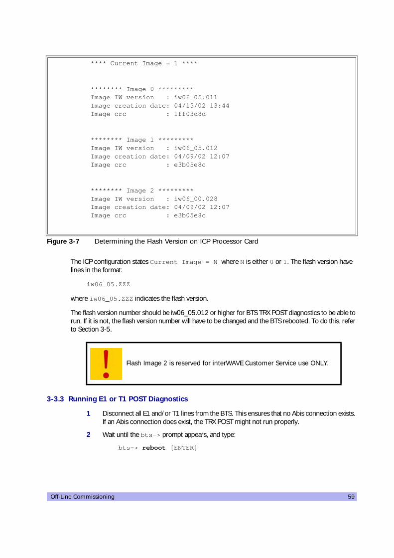
Off-Line Commissioning 59
The ICP configuration states Current Image = N where N is either 0 or 1. The flash version have lines in the format:
iw06_05.ZZZ
where iw06_05.ZZZ indicates the flash version.
The flash version number should be iw06_05.012 or higher for BTS TRX POST diagnostics to be able to run. If it is not, the flash version number will have to be changed and the BTS rebooted. To do this, refer to Section 3-5.
3-3.3 Running E1 or T1 POST Diagnostics
1 Disconnect all E1 and/or T1 lines from the BTS. This ensures that no Abis connection exists. If an Abis connection does exist, the TRX POST might not run properly.
2 Wait until the bts-> prompt appears, and type:
bts-> reboot [ENTER]
**** Current Image = 1 ****
******** Image 0 ********* Image IW version : iw06_05.011 Image creation date: 04/15/02 13:44 Image crc : 1ff03d8d
******** Image 1 ********* Image IW version : iw06_05.012 Image creation date: 04/09/02 12:07 Image crc : e3b05e8c
******** Image 2 ********* Image IW version : iw06_00.028 Image creation date: 04/09/02 12:07 Image crc : e3b05e8c
Figure 3-7 Determining the Flash Version on ICP Processor Card
Flash Image 2 is reserved for interWAVE Customer Service use ONLY.

60 UltraWAVE BTS Installation and Commissioning Guide, Release 6.5A
This action reboots the BTS. The VxWorks kernel is started, several E1 or T1 trunk card tests run sequentially, and the results of each test are listed as PASSED/FAILED. Only if all seven tests passed successfully will the E1 or T1 POST diagnostics be considered successful. The E1 or T1 POST results will be displayed after the boot process has been completed:
3 The above display shows the E1 or T1 POST results that would appear if the E1 or T1 POST diagnostics ran successfully on the E1 or T1 trunk card in slot 1. The format for each diag-nostic line is:
[line number][action][E1 or T1 number][test number][test description][test result]
In the case of an error, a FAILED message would appear following the test that failed. In addition, the following message would be displayed in Line 8:
E1 CARD in SLOT 1: COMPLETED POST/OFFLINE Test: FAILED
3-3.4 Verifying Telnet Communications with the BTS over Ethernet
The Craft PC uses telnet communications across the Ethernet connection for code downloads and to use the proprietary Network Management Interface (NMI) for BTS testing. Before performing any of the following procedures, ensure that you can establish and terminate a telnet communications session as described in the following procedures.
The coding for the E1 or T1 trunk card, its modules and scripts generically refer to the E1 or T1 trunk card objects as “E1”, whether the corresponding ports are configured as E1 or T1.
1 (e1diag) E1 CARD in SLOT 1: STARTING POST/OFFLINE Test
2 (e1diag) testsPtr 0xffb33ab4 testsPtr[0] 0x5
3 (e1diag) testsPtr 0xffb33ab4 testsPtr[0] 0x5 result 0x0 i 1
4 (e1diag) E1(1) TID01: Initialize Peripheral Registers: PASSED
5 (e1diag) testsPtr 0xffb33ab4 testsPtr[0] 0x5 result 0x0 i 2
6 (e1diag) E1(1) TID02: Peripheral Register Test: PASSED
7 (e1diag) testsPtr 0xffb33ab4 testsPtr[0] 0x5 result 0x0 i 3
8 (e1diag) E1(1) TID03: Framer Register Test: PASSED
9 (e1diag) testsPtr 0xffb33ab4 testsPtr[0] 0x5 result 0x0 i 4
10 (e1diag) E1(1) TID04: VME to CPU FIFO Flag Test: PASSED
11 (e1diag) testsPtr 0xffb33ab4 testsPtr[0] 0x5 result 0x0 i 5
12 (e1diag) E1(1) TID05: Initialize Time/Space sw Chip: PASSED
13 (e1diag) testsPtr 0xffb33ab4 testsPtr[0] 0x5 i 6
14 (e1diag) E1 CARD in SLOT 1: COMPLETED POST/OFFLINE Test : PASSED
Figure 3-8 E1 or T1 POST Results
If an E1 or T1 trunk card fails the POST diagnostics, remove the failed card and return it to interWAVE along with its test results file. The defective card needs to be replaced with a new one, and POST diagnostics should be run again on the new card.

Off-Line Commissioning 61
Establishing a Telnet Communications Session
1 In an Xterm window, terminate the serial connection by pressing the [~] key and then the [.] key:
bts-> ~.
The prompt now changes back to build@craftpc:~>.
2 Verify that you can establish a telnet communications session by typing:
build@craftpc:~> telnet iwbox [ENTER]
3 The Craft PC prompt now changes to bts->. This prompt verifies that the telnet session can be established. If this is not the case, verify the Ethernet wiring and retry.
Terminating a Telnet Communications Session
After verifying that a telnet communications session can be established, terminate the telnet session as follows.
4 Terminate the telnet communications session by typing:
bts-> logout [ENTER]
The return message should read “Connection closed by foreign host” and the prompt changes back to build@craftpc->.
3-3.5 Running TRX POST Diagnostics
This section explains how to use the Craft PC to run the TRX POST diagnostics on the BTS.
For more information about the Craft PC, please refer to the interWAVE Craft PC Guide.
If the Craft PC hangs when attempting to establish a telnet session, press the key combination [CTRL][c] to abort the failed connection. Check the boot parameters and repeat the connection procedures. Also verify that the Craft PC host table contains the hostname of your equipment in reference to the default IP address.
Once a telnet session has been established between the Craft PC and the processor card, it must be terminated before the Craft PC is powered off. FAILURE TO DO THIS WILL RESULT IN A HUNG CONNECTION ON THE BSS SYSTEM.
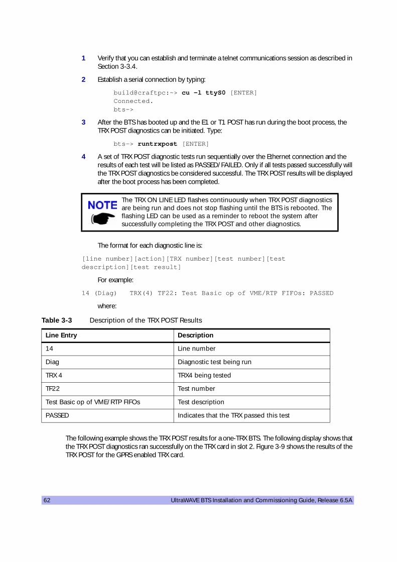
62 UltraWAVE BTS Installation and Commissioning Guide, Release 6.5A
1 Verify that you can establish and terminate a telnet communications session as described in Section 3-3.4.
2 Establish a serial connection by typing:
build@craftpc:~> cu -l ttyS0 [ENTER] Connected. bts->
3 After the BTS has booted up and the E1 or T1 POST has run during the boot process, the TRX POST diagnostics can be initiated. Type:
bts-> runtrxpost [ENTER]
4 A set of TRX POST diagnostic tests run sequentially over the Ethernet connection and the results of each test will be listed as PASSED/FAILED. Only if all tests passed successfully will the TRX POST diagnostics be considered successful. The TRX POST results will be displayed after the boot process has been completed.
The format for each diagnostic line is:
[line number][action][TRX number][test number][test description][test result]
For example:
14 (Diag) TRX(4) TF22: Test Basic op of VME/RTP FIFOs: PASSED
where:
The following example shows the TRX POST results for a one-TRX BTS. The following display shows that the TRX POST diagnostics ran successfully on the TRX card in slot 2. Figure 3-9 shows the results of the TRX POST for the GPRS enabled TRX card.
The TRX ON LINE LED flashes continuously when TRX POST diagnostics are being run and does not stop flashing until the BTS is rebooted. The flashing LED can be used as a reminder to reboot the system after successfully completing the TRX POST and other diagnostics.
Table 3-3 Description of the TRX POST Results
Line Entry Description
14 Line number
Diag Diagnostic test being run
TRX 4 TRX4 being tested
TF22 Test number
Test Basic op of VME/RTP FIFOs Test description
PASSED Indicates that the TRX passed this test
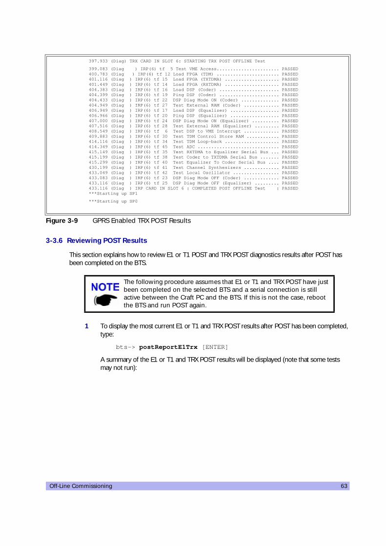
Off-Line Commissioning 63
3-3.6 Reviewing POST Results
This section explains how to review E1 or T1 POST and TRX POST diagnostics results after POST has been completed on the BTS.
1 To display the most current E1 or T1 and TRX POST results after POST has been completed, type:
bts-> postReportE1Trx [ENTER]
A summary of the E1 or T1 and TRX POST results will be displayed (note that some tests may not run):
397.933 (Diag) TRX CARD IN SLOT 6: STARTING TRX POST OFFLINE Test
399.083 (Diag ) IRP(6) tf 5 Test VME Access....................... PASSED 400.783 (Diag ) IRP(6) tf 12 Load FPGA (TDM) ....................... PASSED 401.116 (Diag ) IRP(6) tf 15 Load FPGA (TXTDMA) .................... PASSED 401.449 (Diag ) IRP(6) tf 14 Load FPGA (RXTDMA) .................... PASSED 404.383 (Diag ) IRP(6) tf 16 Load DSP (Coder) ...................... PASSED 404.399 (Diag ) IRP(6) tf 19 Ping DSP (Coder) ...................... PASSED 404.433 (Diag ) IRP(6) tf 22 DSP Diag Mode ON (Coder) .............. PASSED 404.949 (Diag ) IRP(6) tf 27 Test External RAM (Coder) ............. PASSED 406.949 (Diag ) IRP(6) tf 17 Load DSP (Equalizer) .................. PASSED 406.966 (Diag ) IRP(6) tf 20 Ping DSP (Equalizer) .................. PASSED 407.000 (Diag ) IRP(6) tf 24 DSP Diag Mode ON (Equalizer) .......... PASSED 407.516 (Diag ) IRP(6) tf 28 Test External RAM (Equalizer) ......... PASSED 408.549 (Diag ) IRP(6) tf 6 Test DSP to VME Interrupt ............. PASSED 409.883 (Diag ) IRP(6) tf 30 Test TDM Control Store RAM ............ PASSED 414.116 (Diag ) IRP(6) tf 34 Test TDM Loop-back .................... PASSED 414.349 (Diag ) IRP(6) tf 45 Test ADC .............................. PASSED 415.149 (Diag ) IRP(6) tf 35 Test RXTDMA to Equalizer Serial Bus ... PASSED 415.199 (Diag ) IRP(6) tf 38 Test Coder to TXTDMA Serial Bus ....... PASSED 415.299 (Diag ) IRP(6) tf 40 Test Equalizer To Coder Serial Bus .... PASSED 430.199 (Diag ) IRP(6) tf 41 Test Channel Synthesizers ............. PASSED 433.049 (Diag ) IRP(6) tf 42 Test Local Oscillator ................. PASSED 433.083 (Diag ) IRP(6) tf 23 DSP Diag Mode OFF (Coder) ............. PASSED 433.116 (Diag ) IRP(6) tf 25 DSP Diag Mode OFF (Equalizer) ......... PASSED 433.116 (Diag ) IRP CARD IN SLOT 6 : COMPLETED POST OFFLINE Test : PASSED ***Starting up SP1
***Starting up SP0
Figure 3-9 GPRS Enabled TRX POST Results
The following procedure assumes that E1 or T1 and TRX POST have just been completed on the selected BTS and a serial connection is still active between the Craft PC and the BTS. If this is not the case, reboot the BTS and run POST again.

64 UltraWAVE BTS Installation and Commissioning Guide, Release 6.5A
3-3.7 Rebooting the BTS after Running POST
1 Type:
bts-> reboot [ENTER]
This action places the TRX in an on-line and operational state.
2 Reconnect all E1 or T1 lines to the BTS.
3-3.8 Terminating Serial Communications with the BTS
bts:> postReportE1Trx
******************* E1 DIAGNOSTICS REPORT *******************
*************************************************************
Slot:1
E1(1)TID01: Initialize Peripheral Registers : PASS E1(1)TID02: Peripheral Register Test : PASS E1(1)TID03: Framer Register Test : PASS E1(1)TID04: VME to CPU FIFO Flag Test : PASS E1(1)TID05:Initialize Time/Space sw Chip : PASS E1(1)TID06: Software Download Test : Not-Run E1(1)TID07: Memory Test : Not-Run E1(1)TID08: CPM download Test : Not-Run E1(1)TID09: TRAU DSP Test : Not-Run E1(1)TID10: Cross Connect Test : Not-Run *************************************************************
******************* TRX DIAGNOSTICS REPORT ******************
*************************************************************
Slot 6
-------------------------------------------------------------
All Tests PASSED
*************************************************************
value=58=0x3a='="
bts:>
Figure 3-10 Reviewing E1 or T1 and TRX POST Results
There are five tests that are not run but show up in the results section when the user manually retrieves the POST results. These tests are not displayed when running POST by rebooting the BTS. They are:• T1(1) TID06: Software Download Test : Not-Run • T1(1) TID07: Memory Test : Not-Run • T1(1) TID08: CPM Download Test : Not-Run • T1(1) TID09: TRAU DSP Test: Not-Run • T1(1) TID10: Cross Connect Test: Not-Run
If you are going to perform the Racal tests described in the interWAVE Radio Test Manual at this time, ensure that you have rebooted the chassis. Also, leave the Craft PC connected to the IWP card and a serial communications session active.

Off-Line Commissioning 65
1 Close the serial connection by placing your cursor in the Xterm window which was used to establish a serial connection, and press the [~] key and the [.] key.
2 After a few seconds the returned message should read Disconnected, and the display will revert back to build@craftpc:-> prompt.
3-4 Exiting XWindows on the Craft PC
This section explains how to close XWindows running the Windows 2000/XP operating system on the Craft PC.
1 If XWindows is running, at the prompt, type: exit [ENTER]
2 Left click the X in the upper right hand corner of your XWindows window.
Specific shutdown instructions MUST be followed when powering off the Craft PC. DO NOT POWER OFF THE CRAFT PC BY PRESSING THE POWER BUTTON. Use the shutdown instructions included in Section 3-4.

66 UltraWAVE BTS Installation and Commissioning Guide, Release 6.5A
3-5 Upgrading the BTS Software Version (Flash)
Use this procedure if the procedures in Section 3-3.1 indicate that you need to update your software version.
The BTS stores its release software in Flash RAM. This section explains how to upgrade the BTS Flash boot image locally using the Craft PC.
1 Power up the Craft PC and start the XWindows environment. For Craft PC power-up procedures, refer to Section 3-2.2. For XWindows start-up procedures, refer to Section 3-2.2.
2 Verify that a telnet session can be established with the BTS. In an Xterm window, type:
build@craftpc:~> telnet iwbox [ENTER]
3 If the Ethernet connection is setup correctly, then the Craft PC returns the VxWorks bts-> prompt. If this is not the case, refer to Section 3-3.4 for setup procedures.
4 Once the Ethernet connection has been tested, terminate the telnet session by typing:
bts-> logout [ENTER]
5 The Craft PC returns the build@craftpc:~> prompt. Establish a serial session with the BTS. In an Xterm window, type:
build@craftpc:~> cu -l ttyS0 [ENTER]
Identify Your Processor Card
6 Change the working directory to the directory containing the new software version you wish to upgrade to the BTS:
cd "/home/build/iwXX_YY.ZZZ/iwlib/platform/bspppc" [ENTER]
The iwXX_YY.ZZZ parameter represents the new software version you wish to load on the BTS.
7 To find out which Flash image in which the current software version resides, type:
bts-> getCurrentImage [ENTER] value = 0 = 0x0
Make a note of the returned value, which might be either 0 or 1. This is the active image in which the current Flash resides. The binary opposite of this value will be used to load the new Flash in the following steps.
In order to update the BTS Flash boot image locally using the Craft PC, the Craft PC hard drive must contain the software version (Flash boot image) to be installed. If the required release is not installed on your Craft PC, use the procedures in the interWAVE Craft PC Guide to install it.

Off-Line Commissioning 67
If Current Image Value is 0 (value = 0 = 0x0)
8 Load the new Flash in the inactive image. At the bts-> prompt, type:
bts-> writeFlashImage “btsflash.bin”, 1 [ENTER]
9 This takes about one minute. When the bts-> prompt returns, set the inactive image containing the new Flash as the active or current image, type:
bts-> setImageCurrent 1 [ENTER]
10 Reboot the BTS for the new Flash image to take effect by pressing the key combination [CTRL][x].
If Current Image Value is 1 (value = 1 = 0x1)
11 Load the new Flash in the inactive image. At the bts-> prompt, type:
bts-> writeFlashImage “btsflash.bin”, 0 [ENTER]
12 This takes about one minute. When the bts-> prompt returns, set the inactive image containing the new Flash as the active or current image, type:
bts-> setImageCurrent 0 [ENTER]
13 Reboot the BTS for the new Flash image to take effect by pressing the key combination [CTRL][x].
The Flash boot image has been upgraded to the new software version and set as the default.
Flash Image 2 is reserved for interWAVE Customer Service use ONLY.
68 UltraWAVE BTS Installation and Commissioning Guide, Release 6.5A
3-6 Post Off-Line Commissioning
The following post off-line commissioning procedures are necessary to ensure that the BTS is ready for on-line commissioning. In the case of off-line commissioning at a staging area, these procedures ensure that the BTS is ready for installation. In the case of off-line commissioning after on-site installation, these procedures ensure that the BTS is ready for on-line commissioning.
Post Off-Line Commissioning Procedures at the Staging Area
1 Repack the BTS in its original shipping containers and make sure that it is shipped to the site where it will be installed.
2 Once the BTS is installed at its final site as described in Chapter Two, continue with the next section.
Post Off-Line Commissioning Procedures On-Site
1 Reconnect the E1 or T1 cables to the digital distribution frame.
2 Power on the BTS if it is not already on. Verify that all PWR and ON LINE LEDs are green.
3 Inform the OMC operator that the BTS is ready for network configuration.
4 After the OMC operator has configured the BTS, continue with on-line commissioning tests in the next chapter.

Off-Line Commissioning of a Daisy Chain 69
FourOff-Line Commissioning of a Daisy Chain
40000
Up to four UltraWAVE BTSs, WAVEXpress BTSs and/or TurboMAX BTSs can be incorporated into a daisy chain connected to a BSC. If this configuration is used, each BTS must be installed separately, and must have off-line commissioning procedures independently performed. Once each BTS is installed and commissioned, the BTSs can be daisy chained together.
4-1 Prerequisites to Daisy Chaining
1 Ensure that all BTSs comprising the daisy chain are installed and off-line commissioned.
Refer to Chapter Two and Chapter Three for instructions on how to install and off-line configure the BTSs that are part of the daisy chain.
2 Ensure that the Abis Manager timeslot has been set for each BTS in the daisy chain as described in Section 4-2. Each Abis link within this daisy chain MUST be allocated a different Abis timeslot number.
3 Turn the power off to all units.
4 Using the instructions in Section 2-5.3, verify that all E1 and/or T1 lines are in place and commissioned by the operator from the BSC to the first BTS, and between all successive BTSs comprising the daisy chain.
If the power fails to one of the units or one of the units in a daisy chain is rebooted, communication with the downstream units will not be lost.

70 UltraWAVE BTS Installation and Commissioning Guide, Release 6.5A
4-2 Setting the Abis LAPD Signaling Timeslot
This procedure sets the Abis LAPD timeslot between the MSC and each BTS. If the Abis timeslot is not set, it automatically defaults to 16.
This procedure is optional for a star configured BTS, but is required for all BTSs which will be used in a daisy chain. In this case, each BTS must have its Abis timeslot set to a unique number in the chain. This information will be used by the OMC operator to configure the daisy chain.
1 Ensure that the Craft PC is connected to the BTS over a serial line, and that a serial connection is established. Refer to Chapter Three for instructions on how to do this.
2 In an Xterm window, type:
bts-> getFlashE1Chan [ENTER]
This displays the timeslot reserved for the Abis LAPD signalling timeslot, which is by default set to 16. To change this value, type at the prompt:
bts-> setFlashE1Chan <number> [ENTER]
where <number> is the Abis LAPD signaling timeslot assigned to an unassigned T1 channel between 1 and 24 or to an unassigned E1 channel between 1 and 31.
3 To double-check that the timeslot was changed, type again:
bts-> getFlashE1Chan [ENTER]
The new Abis signaling timeslot number should be displayed.
4 If the Abis signaling timeslot was changed, the BTS must be rebooted. Type:
bts-> reboot [ENTER]
This procedure must be performed after the BTS is tested using a Racal testset. Refer to the interWAVE Field Maintenance Guide for further instructions.
The Abis signaling timeslot for each BTS in the daisy chain must be set to a different number. For example:• BTS 1 in the chain = Set timeslot 16 as the Abis timeslot• BTS 2 in the chain = Set timeslot 17 as the Abis timeslot• BTS 3 in the chain = Set timeslot 18 as the Abis timeslot• BTS 4 in the chain = Set timeslot 19 as the Abis timeslotMake sure that this information is communicated to the OMC operator.

On-Line Commissioning 71
FiveOn-Line Commissioning
50000
On-line commissioning takes place on-site after installation and off-line commissioning. Its purpose it to verify that the equipment is operational and can be integrated into the telecommunications network.
On-line commissioning requires the participation of two people; a field technician who operates and tests the BTS on-site and an OMC operator who remains as the OMC console. These two must work together, performing the procedures in this chapter in conjunction with the procedures in the WAVEView OMC Configuration Guide.
The procedures in this chapter are divided into four sections:
• Pre on-line commissioning, where you ensure that the system is ready for online commissioning.
• On-line commissioning, where you test that the system is ready to operate as an integral part of the network.
• Verifying RF performance, where you perform RF-related measurements.
• Post online commissioning.
Radio Frequency Radiation WarningUnder normal operating conditions, interWAVE Communications radio equipment complies with the limits for human exposure to radio frequency (RF) fields adopted by the Federal Communications Commission (FCC). All interWAVE Communications, Inc. radio equipment is designed so that under normal working conditions radio frequency radiation directly from the radio is negligible when compared with the permissible limit of continuous daily exposure recommended in the United States of America by ANSI/IEEE C95.1-19991 (R1997), Safety Levels with Respect to Human Exposure to Radio Frequency Electromagnetic Fields, 3 kHz to 300 GHz.Radio frequency signal levels that give rise to hazardous radiation levels can exist within the transmitter, power amplifiers, associated RF multiplexers and antenna systems.Do not disconnect RF coaxial connectors on the interWAVE equipment or antenna systems while the radio equipment is operating. Never place any body part over, or look into any RF connector while the radio equipment is transmitting.

72 UltraWAVE BTS Installation and Commissioning Guide, Release 6.5A
5-1 Pre On-Line Commissioning Requirements
Before on-line commissioning begins, the field technician or the OMC operator must verify that:
• The BSC or BS Plus, and the WXC or MSC are fully commissioned, in service and connected to each other and to the BTS.
• The OMC is in service and connected to the BSC via the MSC as defined in the interWAVE Network Implementation Manual.
• The database questionnaire is completed, with all necessary BTS parameters listed, as defined in the interWAVE Network Implementation Manual.
• The OMC operator has successfully created and configured the BTS object on the OMC and downloaded this information to the BTS.
• The RF frequencies are cleared to transmit.
• The E1 or T1 connection between the BTS and the BSC has been commissioned.
• The BSC-BTS E1 or T1 link is properly certified. Note that the certification should state length of testing and BER results.
• The HLR subscriber data has been entered into the HLR using the Subscriber Management GUI, as described in the interWAVE Subscriber Management Guide. In particular, the HLR must be configured to support the SIM cards of the mobiles used by the field technician.
• The Abis link and its child objects are locked at the OMC.
Once the E1 or T1 link has been properly connected to the BTS E1 or T1 trunk card, both port alarm LEDs for the connected port should turn off. If one or both LEDs remain lit, signifies an E1 or T1 link problem related to either a faulty connector or the E1 or T1 link itself. Refer to the interWAVE Field Maintenance Guide for additional information.
It is the operator's responsibility to verify that all BSC-BTS E1 or T1 Abis links are ordered, installed and certified by the local telephone provider. Certification should include a bit error ratio/rate test of at least 20 minutes on the Abis interface, with a BER of 10-8 or better.

On-Line Commissioning 73
5-2 On-Line Commissioning
The network commissioning procedures must be performed at the OMC and at the NIB. This requires two persons working from two different documentation sets:
• A field technician who remains on site. They must have a filled out copy of Checklist 2 and a copy of this manual.
• An OMC operator who remains at the OMC. They must have a copy of the WAVEView OMC Configuration Guide.
The following flowchart provides a high-level view of the procedures. The procedures in the following sections provide detailed, numbered steps.
Checklist 3 summarizes the steps for on-line commissioning.
Before starting any of the following procedures, the field technician needs to ensure that anti-static precautions are taken.

74 UltraWAVE BTS Installation and Commissioning Guide, Release 6.5A
Figure 5-1 On-Line Commissioning Procedures
.������=�%!4������<���
�=���������<��'
/��4< *���!���
.������=���������%����� .������=���'
"�����'��������:����4��
:4���
'����� ����'�����
"��
'����� ����'�����
"#
�=���������<��'
�=���������<��'
'����$�����(��
�����
'���0�=����=����(����������������
'���1*4����������(����!���
'���2�����������
��!���
�=�����������:���
����4���:4���
�=���<����������:�����������4����
:4���
�=���<����'�����
/��4< �;�����������
'���������;������
�����
/��4< ����4������
'���3.���!4����:��4< �4������
$����=���'
-���- � �� 8��1�!�9��9��
"&� �''
��������
On-Line Commissioning 75
Before disconnecting the E1 or T1 cables, the field technician must make sure that the cable is labeled in a way that clearly identifies its origin (a particular E1 or T1 port of the BSC, or a particular port of an E1 or T1 panel, etc.) and destination (a particular E1 or T1 slot and port on the BSC).
• Provide the OMC operator with all part, revision and serial numbers for the BTS cards and modules. This information was gathered during the physical installation and is available in Checklist 1.
Recovery Tests
1 At the installation site, power off the BTS. Have the OMC operator verify the changed state of the BTS.
2 At the installation site, power on the BTS. Have the OMC operator verify the changed state of the BTS.
3 Have the OMC operator lock the E1 or T1 ports, and verify that BTS alarms appear.
4 Have the OMC operator unlock the E1 or T1 ports, and verify that BTS alarms clear.
5 At the BTS, disconnect all E1 and/or T1 cables. Monitor the LED sequence of the BTS as described in Chapter Three.
6 Reconnect both E1 and/or T1 cables to the BTS E1 or T1 trunk card. Monitor the LED sequence of the BTS as described in Chapter Three.
External Alarm Tests
1 Test external alarms as per the following procedures:
Test 1
A Open the door of the BTS.
B After a delay, the OMC operator must observe an alarm event.
C Close the door.
D After a delay, the alarm state displayed at the OMC changes from open to closed.
Test 2
A If the first external alarm is used, close the alarm relay (i.e. trigger the first customer-defined alarm).
B After a delay, the OMC operator must observe an alarm event.
C Close the alarm relay by opening the alarm contact.
D After a delay, the alarm state displayed at the OMC changes from open to closed.
Before starting any of the following procedures, the field technician needs to ensure that anti-static precautions are taken.

76 UltraWAVE BTS Installation and Commissioning Guide, Release 6.5A
Test 3
A If the second external alarm is used, close the alarm relay (i.e. trigger the second customer-defined alarm).
B After a delay, the OMC operator must observe an alarm event.
C Close the alarm relay by opening the alarm contact.
D After a delay, the alarm state displayed at the OMC changes from open to closed.
TCH Timeslot Tests
1 In this test, the OMC operator unlocks individual TCH timeslots and the field technician places a mobile-to-mobile call over each timeslot using a mobile handset in debug mode. Refer to the documentation provided by the module handset manufacturer for the proper procedures.
For each timeslot, the commissioner should verify that:
• The timeslot displayed on the handset corresponds to the timeslot unlocked by the OMC operator.
• A two-way call is completed successfully.
• The call has good audio quality and power, and low interference.
The number of timeslots to be tested differs depending on whether you have one, two or three TRXs. Table 5-1 provides the sequence for 1 TRX, Table 5-2 provides the sequence for 2 or more TRXs.
Table 5-1 Timeslots Needing Testing in a One-TRX BTS
TRX Number Timeslot Number Channel Type Testing Necessary
First TRX (TRX in Slot 6)0 BCCH Combined No
1 TCH Yes
2 TCH Yes
3 TCH Yes
4 TCH Yes
5 TCH Yes
6 TCH Yes
7 TCH Yes
Note: To run an abbreviated version of this test, test any one of timeslots 0-3 and of timeslots 4-7 on each TRX.

On-Line Commissioning 77
Table 5-2 Timeslots Needing Testing in BTS with More Than One TRX
TRX Number Timeslot Number Channel Type Testing Necessary
First TRX (Note) 0 BCCH No
1 SDCCH No
2 TCH Yes
3 TCH Yes
4 TCH Yes
5 TCH Yes
6 TCH Yes
7 TCH Yes
Second through Sixth TRX (Note) 0 TCH Yes
1 TCH Yes
2 TCH Yes
3 TCH Yes
4 TCH Yes
5 TCH Yes
6 TCH Yes
7 TCH Yes
Note: The BCCH can be assigned to any TRX within the BTS. The label “First TRX” applies to the TRX to which is assigned the BCCH. The OMC operator may determine which physical TRX is the “First”. All TCH timeslots on the second through sixth TRX must be tested.
78 UltraWAVE BTS Installation and Commissioning Guide, Release 6.5A
5-3 Antenna Cabling and Power Verification
5-3.1 Voltage Standing Wave Ratio (VSWR) Check
The VSWR check should be performed by the team responsible for the antenna installation. The purpose of the check is to ensure the integrity of the antenna and the antenna connection by determining whether the reflected power reading is higher than the recommended value. The reflected power is defined as a ratio of the power output versus the reflected power return. This value is determined by two key factors: the power output from the chassis and the loss due the length and type of the cable.
The recommended test approach is to use an in-line, forward/reverse power meter (for example, the NAS model by Rohde and Schwarz) installed between the chassis and the antenna cable. This approach validates that the antenna and cable are good. It also verifies that the transmit power from the chassis is within tolerance limits. The VSWR at the antenna port should be less than or equal to 1.5:1.
Listed below are threshold values assuming a VSWR of 1.5 at different levels of cable loss (due to length or cable type). The estimated return loss should be greater than or equal to the values below.
5-3.2 Verifying BTS RF Performance without Racal
After performing the BTS commissioning as described in the previous section, use the following procedure to check the performance of an on-line BTS without using a Racal test procedure.
Required Test Equipment
• GSM-compatible RF Power Meter
• 50 Ohm dummy load
• 100 W, 30 dBm attenuator
• Two mobile telephones
Required Network Configuration
To perform satisfactory RF performance tests, the BTS must be connected to an operational BSC/MSC and OMC to enable call processing, as the SS7 must be enabled for the BTS to transmit. Make sure you commission the BTS as described in the previous section before performing this procedure.
5-3.3 Verifying TRX Output Power
This test must be done to each TRX in the system. After completing the test for the first TRX, move on to the next until you have tested each. Use the following procedure:
This procedure is NOT a substitute for the Racal tests. Please refer to the interWAVE Radio Test Manual to test the output power of the BTS.
On-Line Commissioning 79
1 At the OMC, make sure that the BTS is in a locked state.
2 Disconnect the appropriate antenna cable from cabinet. This cable will correspond to the TRX which you are testing. See Section 2-6 for additional RF cabling information.
3 Ensure that the OMC is configured so that the BCCH is on the TRX you are testing.
4 Connect the dummy load to the “out” port of the RF Power Meter.
5 For each TRX, connect the “in” port of the RF Power Meter to the RFD as follows.
6 At the OMC, change the BTS state to unlocked.
7 Note the output power of the TRX on the power meter; this will be displayed in either Watts or dBm.
8 Complete these steps for each TRX in turn until you have tested them all.
If a TRX falls out of the margins, interWAVE recommends that you perform a Racal test to determine the serviceability of the TRX.
5-3.4 RX BER Measurements
The objectives of this test are to verify the performance of the Receive path of the BTS and the operation of the RX module in the TRX. Before these tests can take place the BTS must be returned to its original “on air” working state with call processing possible.
1 From an Xterm window on the OMC, telnet to the BSC controlling the BTS to be tested, or alternatively connect directly to the BSC with the Craft PC.
2 From the BSC prompt find the IP address of the BTS by typing:
HD:bsc-> ifShow “ppp” [ENTER]
A list of PPP connections will then be displayed. Look for the IP address of the BTS you will be testing. The last number of the “192.168.5.x” address relates to the BtsMgr number of the BTS.
3 From the BSC prompt type the following to connect to the BTS:
HD:bsc-> rlogin “192.168.5.x” [ENTER]
If this is successful you will receive the bts-> prompt.
4 From the BTS prompt type the following to activate the RX BER logging:
bts-> log_none [ENTER] bts-> log_lapdm [ENTER] bts-> setdontarray 0x43,0 [ENTER]
The procedure for BCCH reconfiguration can be found in the Network Configuration section of the WAVEView OMC Configuration Guide.
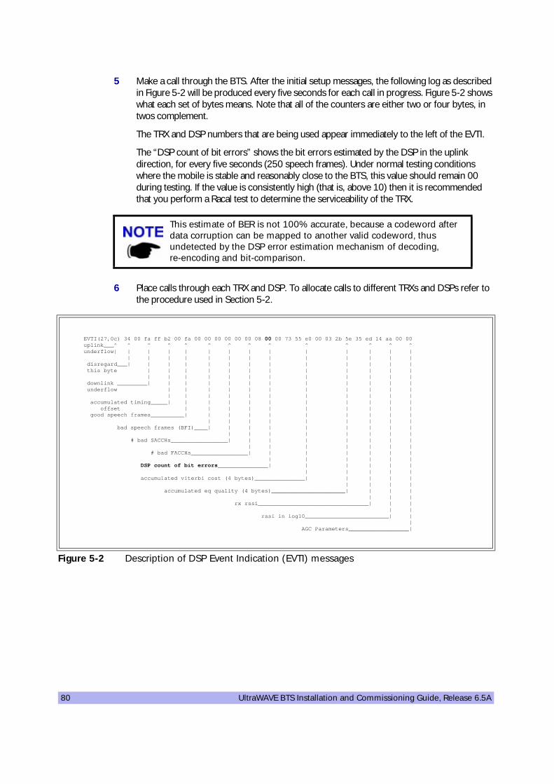
80 UltraWAVE BTS Installation and Commissioning Guide, Release 6.5A
5 Make a call through the BTS. After the initial setup messages, the following log as described in Figure 5-2 will be produced every five seconds for each call in progress. Figure 5-2 shows what each set of bytes means. Note that all of the counters are either two or four bytes, in twos complement.
The TRX and DSP numbers that are being used appear immediately to the left of the EVTI.
The “DSP count of bit errors” shows the bit errors estimated by the DSP in the uplink direction, for every five seconds (250 speech frames). Under normal testing conditions where the mobile is stable and reasonably close to the BTS, this value should remain 00 during testing. If the value is consistently high (that is, above 10) then it is recommended that you perform a Racal test to determine the serviceability of the TRX.
6 Place calls through each TRX and DSP. To allocate calls to different TRXs and DSPs refer to the procedure used in Section 5-2.
This estimate of BER is not 100% accurate, because a codeword after data corruption can be mapped to another valid codeword, thus undetected by the DSP error estimation mechanism of decoding, re-encoding and bit-comparison.
Figure 5-2 Description of DSP Event Indication (EVTI) messages
EVTI(27,0c) 34 00 fa ff b2 00 fa 00 00 00 00 00 00 08 00 00 73 55 e0 00 03 2b 5e 35 ed 14 aa 00 00 uplink___^ ^ ^ ^ ^ ^ ^ ^ ^ ^ ^ ^ ^ ^ underflow| | | | | | | | | | | | | | | | | | | | | | | | | | | disregard___| | | | | | | | | | | | | this byte | | | | | | | | | | | | | | | | | | | | | | | | downlink _________| | | | | | | | | | | | underflow | | | | | | | | | | | | | | | | | | | | | | accumulated timing_____| | | | | | | | | | | offset | | | | | | | | | | good speech frames__________| | | | | | | | | | | | | | | | | | | bad speech frames (BFI)____| | | | | | | | | | | | | | | | | # bad SACCHs_________________| | | | | | | | | | | | | | | # bad FACCHs_________________| | | | | | | | | | | | | DSP count of bit errors_______________| | | | | | | | | | | accumulated viterbi cost (4 bytes)_______________| | | | | | | | | accumulated eq quality (4 bytes)______________________| | | | | | | rx rssi_________________________________| | | | | rssi in log10_________________________| | | AGC Parameters__________________|

On-Line Commissioning 81
5-4 Post On-Line Commissioning Procedures
1 Leave the power to the BTS on.
2 Check that all E1, T1 and power cable connections to the BTS are tight.
3 Close and lock the BTS door.
4 Inform the OMC operator that the BTS is ready for integration testing.
5 Ensure that the BTS site is left in a tidy state.
This concludes the commissioning of the BTS. The field technician can now leave the BTS site.

82 UltraWAVE BTS Installation and Commissioning Guide, Release 6.5A
(this page intentionally left blank)

Site Readiness Checklist 83
Checklist 1Site Readiness Checklist
60000
Environmental requirements
1 __ Ground and soil resistance measured2 __ Air conditioning available
Electrical requirements
1 __ Site ground plate/ring installed and grounding rods connected2 __ Grounding bar Installed on shelter/cabinet and bonded to site ground plate/ring3 __ Main feeder bend radius verified4 __ Power cable entry supports/conduits installed5 __ Main power cable installed and ready for connection6 __ Power utility meter installed and connected7 __ Main power supply available8 __ MCC & MNC frequencies assigned and confirmed9 __ Local electrician/ power provider available
Chassis requirements
1 __ Shelter/Cabinet anchored in position2 __ Foundation pad for shelter/cabinet constructed3 __ Backbone trunking equipment and installation material on site4 __ Shelter/Cabinet waterproofed5 __ PLMN/PSTN/E1/T1 lines installed (BER link measurements)
Site Name
IP Address
BSC Name
MSC Name
Site/Access Phone Number

84 UltraWAVE BTS Installation and Commissioning Guide, Release 6.5A
(this page intentionally left blank)

Installation Checklist 85
Checklist 2Installation Checklist
70000
Unpacking the BTS
Contact interWAVE Customer Service if any visible damage is found.
1 __ No visible damage to shipping materials2 __ All parts included per shipping invoice3 __ Cross check with site specific data to ensure BTS is correctly configured with all cards
Site Name
IP Address
IP Name (optional)
BSC Name
MSC Name
Site/Access Phone Number
Baseband Subrack Slot Number Part Number Revision Number Serial Number
Processor card 0
E1 or T1 Trunk card 1
TRX card 2
TRX card 3
TRX card 4
TRX card 5
TRX card 7
TRX card 7
Clock module -
Power Supply Subrack
Number Part Number Revision Number Serial Number
PS Module 1
PS Module 2
PS Module 3

86 UltraWAVE BTS Installation and Commissioning Guide, Release 6.5A
Mounting
1 __ Attach mounting brackets to chassis2 __ Ground chassis3 __ Connect power supply: 115 VAC, 230 VAC, -48 VDC
Checking VSWR
VSWR measurements are performed by the operator to verify the installation of external antennas.
1 __ VSWR measurement on TX antenna 12 __ VSWR measurement on TX antenna 2 (if applicable)3 __ VSWR measurement on TX antenna 3 (if applicable)
Connecting the BTS
1 __ Connect “Abis Interface” E1 and/or T1 trunk cables to local telephone provider demarcation point2 __ Configure E1 or T1 trunk card DIP switch settings3 __ Ensure power to BTS is off
Verifying the BTS-BSC Link
It is the operator’s responsibility to verify that all BTS-BSC E1 and/or T1 links are ordered, installed and certified by the local telephone provider.
• Verify bit error rates on a nominal 20 minute soak test on the E1 and/or T1 Abis-interface (end-to-end BER test to include E1 and/or T1 trunk cables)

Commissioning Checklist 87
Checklist 3Commissioning Checklist
80000
Off-Line Commissioning
Pre-Commissioning Visual Checks
At the Depot
1 __ Power to BTS is off.2 __ BTS connected to power source.3 __ BTS grounded.4 __ Equipment cables labeled and secured.5 __ Cards seated securely.
On-Site
1 __ Installation secure.2 __ Power to BTS is off.3 __ BTS connected to power source.4 __ BTS grounded.5 __ Equipment cables labeled and secured.6 __ Cards seated securely.7 __ Transmission cables available and labeled.
Compliance Checks
1 __ Cross check with site specific data to ensure BTS is correctly configured with all cards.2 __ Serial number of all cards recorded.3 __ Verify correct operating voltage supplied: 230 VAC, 115 VAC, -48 VDC.
Powering On the BTS
1 __ Disconnect all E1 and/or T1 cables from BTS (if connected).2 __ Turn power to BTS on.3 __ All card power LEDs and processor and E1 or T1 ON LINE LEDs are green.
Site Name
IP Address
IP Name (optional)
BSC Name
MSC Name
Site/Access Phone Number

88 UltraWAVE BTS Installation and Commissioning Guide, Release 6.5A
BTS Off-Line Software Checks
1 __ Connect the Craft PC to the BTS using a serial and ethernet cable.2 __ Establish a serial connection.3 __ Check BTS boot parameters.4 __ Check the flash version number.
POST Tests
1 __ Verify E1 or T1 POST tests successfully passed.2 __ Verify TRX POST tests successfully passed for each card.
TRX Commissioning
1 __ Connect the BTS to the Craft PC and the Racal testset.2 __ Start the Racal.3 __ Load the sequence files on to the PCMCIA card from the CD-ROM.4 __ Setup the test results presentation on the Racal.5 __ Set the offset values for RF cable loss.6 __ Run the automated test sequence: ___ TRX 1 Pass ____ Fail ___ ___ TRX 2 Pass Fail ___ ___ TRX 3 Pass Fail ___ ___ TRX 3 Pass Fail ___ ___ TRX 3 Pass Fail ___ ___ TRX 3 Pass Fail ___
Post Racal Procedures
1 __ Disconnect the BTS from the Racal testset.2 __ Reboot the BTS using the Craft PC.3 __ Disconnect the BTS from the Craft PC.
Post Off-Line Commissioning
At the Depot
1 __ Physically install BTS on-site2 __ Connect E1 and/or T1 lines to telephone provider demarcation point.3 __ Leave power to BTS on.4 __ Inform OMC operator that BTS is ready for on-line commissioning.
On-Site
1 __ Connect E1 and/or T1 lines to telephone provider demarcation point.2 __ Leave power to BTS on.3 __ Inform OMC operator that BTS is ready for on-line commissioning.
On-Line Commissioning
BTS On-Line Commissioning Prerequisites
1 __ BSC in service and connected to BTS.2 __ OMC in service and connected to BSC.3 __ Database questionnaire completed with BTS parameters defined.
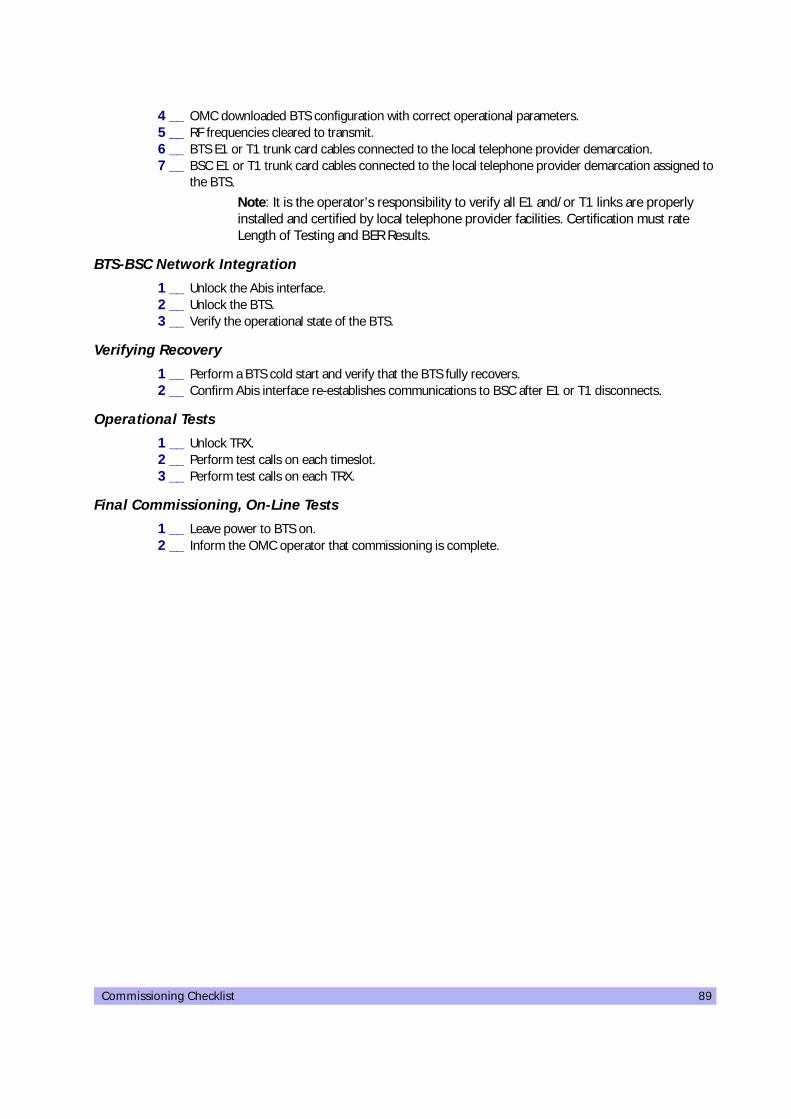
Commissioning Checklist 89
4 __ OMC downloaded BTS configuration with correct operational parameters.5 __ RF frequencies cleared to transmit.6 __ BTS E1 or T1 trunk card cables connected to the local telephone provider demarcation.7 __ BSC E1 or T1 trunk card cables connected to the local telephone provider demarcation assigned to
the BTS.
Note: It is the operator’s responsibility to verify all E1 and/or T1 links are properly installed and certified by local telephone provider facilities. Certification must rate Length of Testing and BER Results.
BTS-BSC Network Integration
1 __ Unlock the Abis interface.2 __ Unlock the BTS.3 __ Verify the operational state of the BTS.
Verifying Recovery
1 __ Perform a BTS cold start and verify that the BTS fully recovers.2 __ Confirm Abis interface re-establishes communications to BSC after E1 or T1 disconnects.
Operational Tests
1 __ Unlock TRX.2 __ Perform test calls on each timeslot.3 __ Perform test calls on each TRX.
Final Commissioning, On-Line Tests
1 __ Leave power to BTS on.2 __ Inform the OMC operator that commissioning is complete.

90 UltraWAVE BTS Installation and Commissioning Guide, Release 6.5A
(this page intentionally left blank)
Index 91
Index
Aalarm
external 43antenna
connecting to the CMA 32
BBTS 32
Ccabling
between multiple WAVEXpress systems 31external 25external BTS 32
changing/verifying boot parameters 56chassis mounting 14checking IWP flash version number 58checklist
commissioning 87installation 85
commissioningonline 71post off-line 68
commissioning checklist 87configuring
E1 or T1 trunk card 18Craft PC
powering down 65customer support xcustomer support services x
Ddaisy chain off-line commissioning 69daisy chain prerequisites 69
EE1
configuring trunk card 18connecting lines 31
E1 or T1 POST diagnostics 59establishing serial communications 55

92 UltraWAVE BTS Installation and Commissioning Guide, Release 6.5A
Ethernet 60external cabling 25
Fflash version number 58front panel LEDs 53
Ggrounding cable 25
Iinstallation 11installation checklist 85interWAVE
customer support xcustomer support services xreturn materials authorization (RMA) xisales operations xisales support xtechnical support xtraining xi
IWP flash version number 58
Llabel
system configuration 4LAPD signaling time slot 70LEDs 53
Mmounting BTS chassis 14
Nnetwork integration 72, 78network integration procedures 73
Ooff-line commissioning 47
daisy chain 69on-line commissioning 71, 73
Index 93
Ppatch level verification 58post installation cabling 46post installation checks 46post off-line commissioning 68post on-line commissioning procedures 81POST results review 63Power On LED Tests 53power supply 25pre on-line commissioning
requirements 72prerequisites
network integration 72, 78prerequisites to daisy chaining 69
Rrebooting BTS after running POST 64requirements
pre on-line commissioning 72return materials authorization (RMA) xireviewing POST results 63RMA xi
Ssales operations xisales support xserial communications 55
terminating 64setting Abis LAPD signaling timeslot 70software
checking current build 58checking software build 58updating 66verification 58verifying 58
software verification 58system
configuration 4type of 4
TT1
configuring trunk card 18connecting lines 31
T1 or E1 POST diagnostics 59technical support x

94 UltraWAVE BTS Installation and Commissioning Guide, Release 6.5A
telnet communications 60establishing 61terminating 61
terminating serial communications with BTS 64training xiTRX POST diagnostics 61
Vverifying BTS performance
without Racal 78verifying current patch level 58verifying current software version 58verifying/changing boot parameters 56Voltage Standing Wave Ratio (VSWR) check 78

Notes
Notes:

Part Number 680208-001/03 Version A
* * * * * * * * * * * * * * * * * *
This is the last page of this document.This notice complies with ISO9001 requirements
and ensures the reader is working from a complete document.
* * * * * * * * * * * * * * * * * *
interWAVE Communications, Inc. 312 Constitution Drive Menlo Park, CA, USA 94025 Phone: 1.650.838.2000 www.iwv.com