ultralight frp pseudospherical shell - iccm · gauss egregium theorem and are seen essential to the...
TRANSCRIPT

ULTRALIGHT FRP PSEUDOSPHERICAL SHELL
G.L.Narasimham 1 and R.Ramesh Kumar 2
1 Composites Group, Vattiyoorkavu, Vikram Sarabhai Space Center,Trivandrum695013,India
2 Structural Engg Group, VRC, Vikram Sarabhai Space Center,Trivandrum695022,India
SUMMARY: A structural synthesis is made for FRP shell structure that does not buckleunder axial load, and is stable up to compressive failure. A multi layer shell constructionwith defined non-geodesic filament orientation and shell wall thickness is determined.From equilibrium and stability requirements the shell surface turns out to be warped orto possess negative Gauss curvature K. They have zero normal curvature for thedirections in which reinforcements run. The definition of isometric deformation is seen asshell bending. Hyperbolic geodesics introduced in this paper are in accordance withGauss Egregium Theorem and are seen essential to the structural stability of thin walledshells. It is viewed as a stability criterion. Generalized Mohr’s circles are drawn todepict changes in curvature during isometric bending. Initially finite element analysis ofreticulated pseudospherical shell is carried out. A multi-layered FRP shell made of highmodulus graphite composite has high resistance to buckling ,with stress at bucklinghighest so far obtained. The design of pseudosphere derived from static equilibrium andstability defined here is independant of length to maximum diameter ratio This sizeindependance is theoretically built into synthesis and as well verified by analysis.
KEYWORDS: Bending, Isometric invariance, Theorema Egregium, Hyperbolicgeodesics, Negative Gauss curvature, Asymptotic directions, Pseudosphere, non-Euclidean hyperbolic geometry ,Generalized Mohr’s circle for isometric bending,Tschebycheff net,inverse isometry.
1. INTRODUCTION :
When glass bottles break, bottlenecks are almost intact. Spinal cord bones have a narrowwaist, same shape prevails from big thigh bone to smaller phalanges of hand or toe.Nylon shopping net bags and fishing nets assume a warped surface in free areas whenloaded, filaments having no normal curvature on net surface. Soap bubble films freelydrawn between two rings exhibit a negative curvature by membrane tension. A flat stripbecomes stiffer after twisting it plastically into a helicoid. These and several suchexamples make one ponder that , after all, there could be some natural economy inmaterial usage in such shapes for optimally balancing buckling instability which getstriggered as bending at elemental structural level.
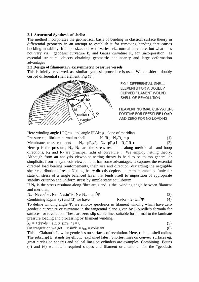
2.1 Structural Synthesis of shells:The method incorporates the geometrical basis of bending in classical surface theory indifferential geometry in an attempt to establish it for removing bending that causesbuckling instability. It emphasizes not what varies, viz. normal curvature, but what doesnot vary viz. geodesic curvature kg and Gauss curvature K, for .incorporation asessential structural objects obtaining geometric nonlinearity and large deformationadvantages2.2 Design of filamentary axisymmetric pressure vesselsThis is briefly reviewed, as similar synthesis procedure is used. We consider a doublycurved differential shell element. Fig (1).
Here winding angle LPQ=ψ and angle PLM=φ , slope of meridian.Pressure equilibrium normal to shell N/R1 +Nο/R2 = p (1)Membrane stress resultants Nφ = pR2/2, Nθ= pR2(1 – R2/2R1) (2)Here p is the pressure, Nφ, Nθ are the stress resultants along meridional and hoopdirections, R1 and R2 are principal radii of curvature . We employ netting theory.Although from an analysis viewpoint netting theory is held to be to too general orsimplistic, from a synthesis viewpoint it has some advantages. It captures the essentialdirected load bearing reinforcements, their size and direction, discarding the negligibleshear contribution of resin. Netting theory directly depicts a pure membrane and funicularstate of stress of a single balanced layer that lends itself to imposition of appropriatestability criterion and uniform stress by simple static equilibrium.If NS is the stress resultant along fiber arc s and ψ the winding angle between filamentand meridian,Nφ= NS cos2Ψ, Nθ= NS sin2Ψ, Nθ/ Nφ = tan2Ψ (3)Combining Equns (2) and (3) we have R2/R1 = 2- tan2Ψ (4)To define winding angle Ψ, we employ geodesics in filament winding which have zerogeodesic curvature or curvature in the tangential plane given by Liouville’s formula forsurfaces for revolution. These are zero slip stable lines suitable for normal to the laminatepressure loading and processing by filament winding.kgE= +dΨ/ds + sin φ sinΨ / r = 0 (5)On integration we get r.sinΨ = rOE = constant (6)This is Clairaut’s Law for geodesics on surfaces of revolution. Here, r is the shell radius.The subscript E, stands for elliptic, explained later . Shortest lines on convex surfaces eg.great circles on spheres and helical lines on cylinders are examples. Combining Equns(4) and (6) we obtain required shapes and filament orientations for the “geodesic

isotensoid ” in terms of elliptic functions. Same cross sectional area of filament rovingsrunning between equator to boss opening radius rOE is used and this yields constantstress along filaments. Sufficiently large number of layers are chosen to isolate bendingfrom stretching. We can employ any other type of geodesic in structural synthesis.We employ the above derivation for synthesis of an axisymmeric shell loaded betweentwo parallel circles. No normal pressure or loading acts. We introduce axial loadsthrough the skin so that direct bending of the laminated shell by a normal loadcomponent is avoided .The loads are transmitted through the shell onto the other end.From Equn (1), normal pressure p acting on the differential element is zero. IntroducingEqun (3) into (1) and , letting k1 =1/R1, k2 =1/R2, we have k1 cos2Ψ +k2 sin
2Ψ =0 (7)This is the Euler expression for normal curvature of a filament kn on a doubly curvedshell that vanishes in this case unlike the geodesic-isotensoid . Zero normal curvaturelines are called asymptotic lines. Examples of asymptotic lines on some surfaces are:(a) A typical saddle point Fig (2). . Parametric representation (x,y,z) = f(u,v)x= u cos v, y= u sin v, z= C.sin 2v.The second surface in Fig (2) has inflexion points atcenter and such a surface was fabricated by Beltrami [ 1]
(b) Straight skewed generators on a one sheet hyperboloid of revolution, r2-z2tan2α=a2, x =a tanh , y=a, z = a tanθ/tanα, α is inclination between generator andz-axis.; r and θ are parameters(c) Hypar or hyperbolic paraboloid surface 2z = x2/a2 _ y2/b2 ; x/a ± y/b = constant, aregenerators, set of parallel line projections inclined at tan -1(b/a) to x- axis. Parametricrepresentation (x,y,z) = f(u,v) is x = a (u+v) ; y = b(u-v) ; z = 2uv;(d) Curved asymptotes with constant winding angle 450 to the principal curvaturedirections on a catenoid of revolution; r = C cosh (z/C) , where C is the minimumdistance of catenary to z-axis of symmetry. This holds for all surfaces of zero meancurvature or minimal surfaces which are physically seen as soap bubble films possessingno bending rigidity .3.1 Hyperbolic curvature and hyperbolic geodesicsLiouville’s formula ([2],pp154) for geodesic curvature is given bykgE= + dΨ/ds+ cos ψ (kg)v=const + sinψ (kg)u=const (8)where right hand side kg are functions of E,F,G and their derivatives with respect toparameters u and v of first fundamental form introduced later.In polar coordinates for axisymmetry, + dΨ/ds + sin φ sinΨ / r = 0 for geodesicsIntegrating this we get r.sin ψ=roE=constant, which are straight lines.In this paper we define hyperbolic curvature by simply changing the sign of ψ inEqun (8),and justify such a change from inversion

kg E,H= ± dψ /ds + sinφ sinψ/r =0 (+ for Elliptic, - for Hyperbolic) kgH= - dΨ/ds + sin φ sinΨ / r = 0Integrating this we get r/sin ψ=roH=constant, circles through origin (9)This is also obtained by putting r in place of roE.roH/r as a process of inversion ofcomplex variable conformal transformation w=1/z .We represent in Fig (3) both the typesof geodesics in two dimensions.. Rectilinear triangle abc in elliptic model is inverted tocurvilinear triangle ABC in a hyperbolic model. The sense of rotation is changed .Radius
of circle or mirror of inversion =(roH.roE)1/2 .and yE � 6 -yH
.It is difficult to accept the hyperbolic model in two dimensions as there is no Euklideancounterpart ([3],pp 275).The definition of geodesic curvature is dependant only on thecoefficients of the first fundamental form and is an intrinsic bending invariant property ineither case.Also the metrics of the above cases in two dimensions are:ds2=dr2+(rdθ)2 and ds2=[dr2+(rdθ)2]/r4 , inverted to a unit circle.Arc lengths should be extremized in each case to be a geodesic We use Euler-Lagrangeequation in Calculus of variations approach.Functional in each case is F= (r2+r’2)½ and F= (r2+r’2)½ /r2
When F is independent of θ , F-r’∂F/∂r’=constant . Performing the integration forEuclidean/Elliptic case we have r sinψ= constant =roE. Likewise for hyperbolic case weget r/sinψ= constant= roH.As ds = rdθ /sinψ we have (sinφ ± dψ/dθ)=0 ; Integrating ψ±θ sinφ = ω (10 )where arbitrary constant ω is the constant angle turned in the tangent plane. For flat Euklidean geometry φ =π /2 , z=y ± θ ( 11)All angles are consistently measured counterclockwise positive, from radius vectortowards elliptic/hyperbolic arcs. In elliptic geodesic,zE constancy means that y+h isthe same angle for the straight line Ee in Fig (3),right. In hyperbolic geodesic,zH

constancy means that y-h is the same angle contained in the “straight line” segmentOHh .3.2 Elliptic and Hyperbolic curvature of a circle in two dimensionsConstant elliptic/euklidean curvature forms a circle. We look at a curve of constanthyperbolic curvature defined here.For a circle in two dimensions in x-y plane we have relationssin ψ /r = (1-T2/r2)/2a ; dψ/ds = (1+T2/r2)/2a ;T2=h2-a2 ( tangent squared or power) (12) adding and subtracting kgE=1/a ; kgH= (a-h2/a)/r2 (13)Curvatures in polar coordinates are expressible as (primes with respect to θ )kgE=(r² +2r’² - rr’’)/(r ² + r’²)3/2 ; kgH=r (r+r’’)/(r ² + r’²)3/2 (14)which have geodesic solutions r=roEsec( θ+ α ) and r=roHcos( θ+ α ) ,0 (15)where roH, roE,α , are all easily recognizable constants in Fig (3)Thus kgE is independent of position , Hyperbolic curvature is position dependent for anarc of a circle. It is positive, zero or negative depending on whether the origin isenclosed, lies on the rim or outside the circle. Fig (3),right.. Some curves of constantpositive and negative kgH are given in Fig (4) for same boundary conditions.
3.3 Justification to consider vanishing kgH as geodesics in this paperFirst justification for considering these hyperbolic lines as geodesics comes from an applicationof Gauss-Bonnet Theorem [2],[3] considered for both cases.° kgE or H ds + ° ° KdA +S (π -a) =2 πHazzidakis theorem ([2],pp 204,prob 17 and [3],pp237, prob 15).deal with a variant of Gauss-Bonnet theorem. The area of a quadrangle enclosed between four elliptic geodesic arcs is (anglesum- 2π) or twice the spherical excess of a geodesic triangle. By the theorem of Hazzidakis whenthis is formed between lines on constant negative K can be regarded also as another type ofgeodesics. Secondly, this has also been demonstrated by Beltrami,([2],pp152) but with reporteddifficulties at edge of regression or cuspidal equator.Thirdly, asymptotic lines on constantnegative K are found to form a Tschebycheff net, the same result arrived at by incorporatingpresent hyperbolic geodesics.[2],(pp204,prob 15).Fourthly, following article 5.3 demonstratesthat Egregium Theorem as asymptotic lines on constant negative K, the same equals (2π -angle

sum). Thus asymptotic a stability theorem of bending invariance only on the assumption ofvalidity of the hyperbolic geodesics. The fifth justification comes from a simple experiment witha nylon shopping bag,like one in Fig(8) bottom. .It has knots on it at regular filament spacing andassumes a definite shape on loading. The distance between nodes ds and polar separation dh ofrhombic cells are constant by knitted construction of vented bags. Thus, ds/dh is a constant.This for each cell or differential shell element equals r/siny. On flattening the bag to drawfilaments to center,they arrange themselves as circles passing through the center with constantradius r/siny=roH. It is noticed that after a small load, filament stress transmitted through theknots increases in that stable configuration, large bending deformations having stopped inproportion. The stable shape is from a pseudosphere family, shown later.
4.1 Models of hyperbolic geometryThere are 3 models of hyperbolic geometry due to Klein, Poincaré and Beltrami. The presentmodel is nearest to Beltrami model in which there appears a limitation for drawing geodesictriangles near to the cuspidal edges. In Fig (5) and Table 1 present model is compared withPoincaré model.
.Table 1 Comparison of hyperbolic geometry models in two dimensionsEuclidian /Elliptic model Poincaré model Present Polar model
Geodesic is a straight line Geodesic is a semi circle Geodesic is a full circle throughorigin
Lines go to infinity ifcontinued on either side
Lines go to x axis if continued Lines go to origin if continued
Points at infinite distance areindefinite
Points at infinite distance are on thex axis
Points at infinite distance are atthe origin
Only one straight linepossible through any twopoints
Only one semi circle possiblebetween any two points
Only one circle through any twopoints. The third point is theorigin.
Two straight lines are parallelif they have a common point
Two semicircles touching the x axisare parallel although intersecting
Two full circles are parallel if theyhave a common tangent at origin

at infinityOnly one line parallel to agiven line through outsidepoint
Two semi circles possible asparallels from an outside point withcommon semicircle tangency.
Only one full circle possible to agiven circle with common tangentat origin
If a line intersects two parallellines, the alternate angles areequal
The alternate angles got by cuttingtwo parallel semi circles are notequal
When a circle intersects twoparallel circles alternate angles areequal
Metricds2=dx2+dy2
Or ds2= dr2+(rdθ)2Metric ds2 = (dx2+dy2)/(y/a)2 Metric
ds2 = (dr2+(rdθ)2)/(r/a)4
Physical analogy is a light raywith constant speed
Physical analogy light ray with speedproportional to y coordinate
Physical analogy light ray withspeed proportional to square ofradial distance from origin
Sum of three internal anglesis π
Sum of three internal angles can beanything
Sum of three internal angles is π
Inversion of hyperbolic model bilinear transformation of complexvariable conformal mapping
Inversion of elliptic model
5.1 Generalized Mohr’s circle of curvatures in isometric bending for positive and negativeK.It is possible to depict normal and twist curvatures on the familiar Mohr circle. This has beendone in a comprehensive way, accommodating isometric bending in this paper.Zero normal curvature direction can occur only on negative K surfaces demarcating positive andnegative normal curvature areas .This is represented on the Mohr’s circle using power of co-axalcircles Fig (6) to include all possibilities by isometric bending .On x-axis is normal curvature and on y-axis twist curvature (or geodesic torsion τg in differentialgeometry parlance) is drawn. Geometrically, the square of semichord or tangents from originsequals of product of intercepts of principal curvatures. As the shell or laminate gets bent to largervalues of k1/k2 with K=k1.k2 remaining constant as per Egregium theorem, a new Mohr circletakes over, at a common point without changing twist curvature or τg. At any instant ψ equalstan-1(-k1/k2)1/2.The same is shown for positive K in.Fig (6).There is equal tangent length for all circles. Square root of Gauss curvature is represented bycommon τg intercept for all circles with negative K and as equal length tangent drawn fromorigin for all circles with positive K. Three circles at left represent negative, zero and positiveK=T² of Equn (12). As per [3], pp 276-279, these geodesics are orthogonal to a group of motionsin plane hyperbolic geometry. Case of K=0 is coinciding with the choice made in the paper.

Physically, this can be demonstrated using a flexible hollow spherical rubber ball cut into twoequal hemispheres. Diametrically opposite points of each half are squeezed together, bent androlled in until it assumes a spindle shape of same constant K. The surface is isometricallydeformed, that is to say, on application of bending and twisting moments, there is no stretching orshear strain in the mid surface of its round wall.Although not so readily apparent, this holds also in bending of negative K sheets of flexiblematerial. Several books on differential geometry deal with isometric mapping and firstfundamental form equivalence between catenoid and helicoid, eg., [2], page 121. By a series ofbend-twist operations a catenoid can be deformed to a heliciod and vice versa. Take a flexiblecatenoid , cut it along a meridian and apply simultaneously bending and twisting moments untilthe nearest circle r = C becomes the straight twisted spine of helicoid . Meridians looking awayfrom center now align straight in the manner of motion of aircraft propeller blades cuttingthrough air in flight. Before bend-twisting principal curvatures were at 0,900 and asymptotesalong ± 450 After bend-twisting, principal curvatures are along ± 450 and asymptotes at 0,90degrees ,ie., there is a swap between the two directions. However, at any point K remains thesame. This example is classical, gives an initial mistaken impression that mean curvature H=0remains the same in isometry, as both the catenoid and helicoid are minimal surfaces. It is notinvariably so . The textbooks on differential geometry that could be accessed by the author donot give isometrically twisted helical surface equivalents to the pseudosphere set, perhaps as it iseasiest to calculate surfaces of revolution.. But it can be calculated from Equn. (30) that followsafter suitable u,v parameterization is assumed.5.2 Isometry depiction using Flexure Potential and Distortion FunctionThe above bending phenomenon can be even more systematically depicted by using a complexvariable isometry function w for any curved surface. Let 1/a = (abs(K))½ = A, where a is thecuspidal radius of pseudosphere or spherical radius in case of constant K.z=A coth(w/2) or w = ln [(A+z)/(A-z)] = (ξ+i g) where complex curvature z=kn+i τg (16)ξ circles are : (x-A coth ξ ).² +y ² =(A/sinh ξ ) ² (17)g circles are : (x+A cot g ).² +y ² =(A/sin g ) ² (18)from which circle center locations and circle radii are obtained. The ξ circles are Apolloniuscircles with respect to poles, ξ=ln(r1/r2),where r1 and r2 are distances from points on Mohr circleto the poles. The g circles contain constant angle g1 on the inter-pole chord.Gauss theorem or other literature in isometry does not identify what varies in isometry as asingle geometrical parameter for each Mohr circle at any stage of bending deformation. For thispurpose, the author introduces the above ξ and g as Flexure potential and Distortion functionrespectively, taking a cue from electrostatics and fluid dynamics. In the former there is electrical
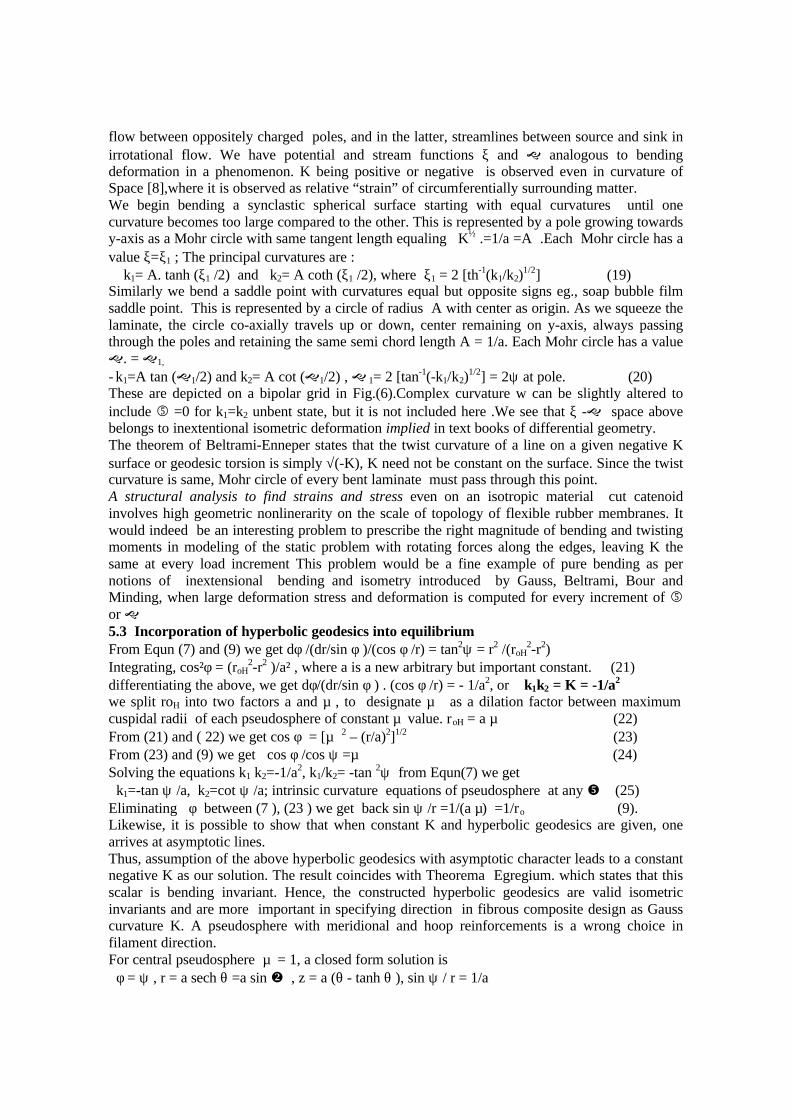
flow between oppositely charged poles, and in the latter, streamlines between source and sink inirrotational flow. We have potential and stream functions ξ and g analogous to bendingdeformation in a phenomenon. K being positive or negative is observed even in curvature ofSpace [8],where it is observed as relative “strain” of circumferentially surrounding matter.We begin bending a synclastic spherical surface starting with equal curvatures until onecurvature becomes too large compared to the other. This is represented by a pole growing towardsy-axis as a Mohr circle with same tangent length equaling K½ .=1/a =A .Each Mohr circle has avalue ξ=ξ1 ; The principal curvatures are : k1= A. tanh (ξ1 /2) and k2= A coth (ξ1 /2), where ξ1 = 2 [th-1(k1/k2)
1/2] (19)Similarly we bend a saddle point with curvatures equal but opposite signs eg., soap bubble filmsaddle point. This is represented by a circle of radius A with center as origin. As we squeeze thelaminate, the circle co-axially travels up or down, center remaining on y-axis, always passingthrough the poles and retaining the same semi chord length A = 1/a. Each Mohr circle has a valueg. = g1,
- k1=A tan (g1/2) and k2= A cot (g1/2) , g 1= 2 [tan-1(-k1/k2)1/2] = 2ψ at pole. (20)
These are depicted on a bipolar grid in Fig.(6).Complex curvature w can be slightly altered toinclude 5 =0 for k1=k2 unbent state, but it is not included here .We see that ξ -g space abovebelongs to inextentional isometric deformation implied in text books of differential geometry.The theorem of Beltrami-Enneper states that the twist curvature of a line on a given negative Ksurface or geodesic torsion is simply √(-K), K need not be constant on the surface. Since the twistcurvature is same, Mohr circle of every bent laminate must pass through this point.A structural analysis to find strains and stress even on an isotropic material cut catenoidinvolves high geometric nonlinerarity on the scale of topology of flexible rubber membranes. Itwould indeed be an interesting problem to prescribe the right magnitude of bending and twistingmoments in modeling of the static problem with rotating forces along the edges, leaving K thesame at every load increment This problem would be a fine example of pure bending as pernotions of inextensional bending and isometry introduced by Gauss, Beltrami, Bour andMinding, when large deformation stress and deformation is computed for every increment of 5or g5.3 Incorporation of hyperbolic geodesics into equilibriumFrom Equn (7) and (9) we get dφ /(dr/sin φ )/(cos φ /r) = tan2ψ = r2 /(roH
2-r2)Integrating, cos²φ = (roH
2-r2 )/a² , where a is a new arbitrary but important constant. (21)differentiating the above, we get dφ/(dr/sin φ ) . (cos φ /r) = - 1/a2, or k1k2 = K = -1/a2
we split roH into two factors a and µ , to designate µ as a dilation factor between maximumcuspidal radii of each pseudosphere of constant µ value. roH = a µ (22)From (21) and ( 22) we get cos φ = [µ 2 – (r/a)2]1/2 (23)From (23) and (9) we get cos φ /cos ψ =µ (24)Solving the equations k1 k2=-1/a2, k1/k2= -tan 2ψ from Equn(7) we get k1=-tan ψ /a, k2=cot ψ /a; intrinsic curvature equations of pseudosphere at any y (25)Eliminating φ between (7 ), (23 ) we get back sin ψ /r =1/(a µ) =1/ro (9).Likewise, it is possible to show that when constant K and hyperbolic geodesics are given, onearrives at asymptotic lines.Thus, assumption of the above hyperbolic geodesics with asymptotic character leads to a constantnegative K as our solution. The result coincides with Theorema Egregium. which states that thisscalar is bending invariant. Hence, the constructed hyperbolic geodesics are valid isometricinvariants and are more important in specifying direction in fibrous composite design as Gausscurvature K. A pseudosphere with meridional and hoop reinforcements is a wrong choice infilament direction.For central pseudosphere µ = 1, a closed form solution is φ = ψ , r = a sech θ =a sin v , z = a (θ - tanh θ ), sin ψ / r = 1/a

The meridian is a tractrix which has a constant tangent length between point of tangency and z-axis.It is also called pseudoradius([2],pp148). Some meridians are shown in Fig (7) for variousvalues of µ. Except the tractrix all are periodic.h is incremeted in equal steps of 6/n to obtain areticulated or discrete model .The constitutive equations above can be also written :(dψ/ds) 2 + cos2ψ / a2 – 1/roH
2 = 0; s=a 3 F(3 ,6 /2-y) ; s=-a .log tan (ψ/2) or 3=1 (26)and d2ψ/ds 2 = K sin ψ. cos ψ ; an intrinsic (ψ - s) relation (27)The synthesis yields a funicular thin-walled shell where load transfer between mutuallyreinforcing filaments occurs at knots or nodes for a disretized reticulated structure and asinterlaminar shear between layers in a continuous balanced shell.
5.4 Tschebycheff net. It is interesting, relevant and useful to find that above equation(27) represents a net with filaments along asymptotic directions of constant negativeGauss curvature K. Surfaces of flexible fishing net having same distance between knots istaken and draped on the surface such that the filaments and knots lie along asymptoticdirections with zero normal curvature. An intrinsic relationship Equn (27) between ψ andarc distance fits in exactly as above. Each rhombus distorts by scissoring action to formneighboring cells in the Tschebycheff net. The pseudosphere described in this report areTschebycheff nets.[ 2], page 204 prob. 15 for various µ values. Fig (8) shows threepseudosphere types.

To design composite shells optimally it is seen that the quotient of principal curvaturesEqun (7) is negative, so also is the product K. We should therefore rule out cylinders,cones (K=0 developable surfaces), and synclastic surfaces (K>0) from normal to theshell equilibrium consideration. Only negative K surfaces that too reinforced only alongthe asymptotic directions. qualify to carry membrane loads. These are saddle shapedpoints called also anticlastic as curvatures are in opposite directions along principalorthogonal directions.When the position vector [r] is described with respect to parameters u and v, there twofundamental forms in surface theory:I ds2 = E du2 + 2F du dv + F dv2 ; (28)II kn ds2 = L du2 + 2M du dv + N dv2 ;(29)Here we introduce Theorema Egregium . The remarkable theorem states that underisometric or bending deformations, Gauss curvature K is invariant. This had beendemonstrated by Gauss. [9]. In the expression for double Gauss curvature
K = (LN – M2) / (EG – F2), (30)the numerator has coefficients L,M,N from the second fundamental form of surfacetheory and is expressible in terms of E,F,G, the coefficients of the first fundamental formand their derivatives with respect to surface generating parameters u and v in acurvilinear coordinate system. The surprising aspect is, the determinant of secondfundamental form LN-M2 getting independent of L,M,N and depending only on E,F,Gand their partial derivatives. This justifies intrinsic stability of hyperbolic geodesics inmembrane state. Some quantities that remain invariant in isometry or isometric mappingas they depend purely on the first fundamental form are : lengths, winding angle orincluded angle between arcs, angle turned in tangential plane ∫kgds,∫∫KdA or integralcurvature (Integra Curvatura as nomenclatured by Gauss ), geodesic curvature of two

types, the second type is defined in this paper, Gauss curvature, geodesic torsion,Christoffel symbols. In structural design and analysis parlance we can say that they donot change by inextensional deformations. That is, there is no midplane extensionalstrain including in-plane shear deformation. The first fundamental form fully coversshell membrane state of stress and strain and the second fundamental form covers thebent state.Some cosequences of this theorem : (1) Surfaces of positive or negative K cannot befaithfully i.e.,isometrically mapped onto a plane without stretching ε or shear distortionc .When we step on an egg shell making it flat,circumferential cracks appear. It isimpossible to map features on the globe on a flat sheet without compromising on inplanestrains ε or c .(2) Direct or full isometry is possible among surfaces of same constant K.(Minding’s Theorem [2],pp 145).Hence, so long as there is bending, we may have widelyvarying principal curvatures k1 and k2, and external shape but a constant product K , likefor example an inverse relationship between pressure and volume of an ideal gas at sametemperature.Gauss theorem is also stated simply as K is an isometric invariant. In Fig (9) is seen anetted construction in which for each rhombic cell length is same but not the elementangle, apparently a contradiction. Textbooks in differential geometry do not fullyillustrate direct and inverse isometry. In inverse isometry the question is asked that if K issame on two surfaces, whether angles and lengths have to be the .same. It is in-planestrain and bending of a single differential element that decides partial isometry. Thispaper defines the two circumstances for which converse requirement is partiallyfulfilled.. That is, if K is constant in a deformation , it does not necessarily mean thatthere has been a strict dual (y-ds) invariant isometric corrospondence, which we can calldirect isometry. In bending,k1=-tany/a, k2=coty/a, normal curvature ratio k1/k2 changes,K and other quantities from first fundamental form cannot change. We see in above Fig(7) how change in local or differential shell element membrane dimensions can produceglobal bending of the structure in three ways. In direct isometry (DI), ds and y areconstant ,(e.g., catenoid/helicoid –classical bending ). In inverse or partial isometrydefined here either ds or y is constant. Retaining same rhombic or diamond cell lengthsds through a dilation factor 3 , y changes by scissoring/shearing action of aTschebycheff net,This is situation (II1) Whereas retaining y conformally, but changingds (and rotations in principal planes, principal curvatures k1and k2 remaining same) withmagnification or contraction occuring through a dilation factor 3, we have situation(II2).This is shown for a square element (y =6 /4).It must be noted that applicability bymaking one differential shell element to hug onto another one is possible only in DI modeby bend-twisting, but not in II1 and II2 modes. The latter modes require the element to bedilated or distorted to make element edges and corner nodes to fall one over the partialisometric equivalent during draping action.
.6.1 K changes by large in-plane circumferential strainingin a circular plateGauss Theorem stipulates no midplane straining as long as K is invariant. By implicationmidplane straining of laminate is associated with change in K. Let us see how this comesabout.

Circumferential straining around a flat point is the simplest way to change K. Take acircular disc of radius R , circumferentially strain it to adjust to large deformations Applya tensile plastic permanent parabolically varying circumferential strain +Kr2/6 by anymeans. This produces a minimum surface area film saddle surface of radius 1/K in twomutually orthogonal directions, as a potato chip. Refer first of Fig (2). Gauss curvatureobtained is negative. Maximum tangential rotations are ± KR, along principal directions.Now instead of tensile we apply compressive strain –Kr2/6 , to obtain a segment of asphere of radius 1/K,maximum tangential rotation or semi-cone angle sin-1(KR).Thus Kthat characterizes bulging or warping of a surfaces is a matter of changing hoop strainin comparision to radial strain by large deformation Von Kármán compatibility, which isneglected in linear formulations. This can be readily demonstrated on flexiblehoneycomb core made by Hexcel Company ,for example. Fig. (9), right pictures.
Flat metric ds2=dr2+(rdh)² is generalised to include circumferential strain ing to a doublycurved shell metric in geodesic polar coördinates as (r→u) ds2=du2+(udh)²(1+Kr2/3)where now u is measured radially along the surface. Constant K axisymmetric meridiansof either sign are simply generated by d²r/ds²+Kr=0 depicting strain around each point.([2],pp146-149)6.2 Strip deformation by differential strainingWhen a long flat strip is twisted to form a helicoid or a part of sphere set, there is
nonlinear parabolic strain distribution across the width. Three types of straining arepossible. Let magnitude of strain at middle be εm Variation of strain εx=± (Ky2/2-εm),+for helicoid, - for sphere set.. For helicoid straining, middle of strip (y=0) strain is –εm
compressive and at extreme fibers at y=±(6εm/K)1/2=2εm tensile. There is no longitudinalstrain εx at y=(2εm/K)1/2.ie Gaussian points. When sign of straining is reversed, i.e.,εx= -(Ky2-εm ),we obtain a segment of a sphere set of constant positive K0. When the flat stripis strained linearly εx=Ey/R, K remains 0 as a developable surface, an annular ringsegment, as in Engineer’s Theory of Bending. Fig (9)

7.1 Stiffness and strength from stability Stability of structures includes strength. and stiffness. Applying above stableconstruction, a computer model on NISA was generated using central pseudospheredesign to replace a glass fiber reinforced plastic 720kg. vibration fixture with steel ofsame frequency , resulting in a design weight 175 kg.[7]. Using composites designed withstability principles as above, it is possible to effect an order of magnitude weight savings.We replace thick laminates by appropriately oriented reticulated beams for strength aswell as stiffnessBending twisting are together handled in isometry in isometry .It can find application inunsteady aerodynamics design to induce or suppress flutter of wings or FRP blades.8.1 K inadequately recognized in design and analysisCallidine [4], chapter 5,12 also refers to the relevance of K during inextensionaldeformations without explicitly mentioning Gauss Theorem or First fundamental form.,but implicitly though Gauss-Codazzi relations of strain compatibility. He also decries thelack of emphasis of K , “ paradoxically, Gauss curvature is given little, if any, emphasisin text books” in his textbook. The author of this paper is of the same opinion. Anotherpertinent comment by Den Hartog [5], page pp 319 relates to unexplained reduction instiffness in bending, but increased stiffness in torsion of pretwisted strips. “It is left as achallenge to the reader, in a subject as a old fashioned as strength of materials, neweffects of considerable numerical importance can still be discovered in the atomic age”.Implicit in stability is loading, static equilibrium and appropriate geodesy. This author’sbelief is strengthened or rather stiffened after investigations in isometry regarding itsimportance and long ignored rôle in structural stability and design.9.0 STRUCTURAL ANALYSIS:9.1 Loading(a) Reticulated Pseudospherical ShellA uniformly distributed compressive load is applied along the meridian of PS at its biggerand smaller ends. The axial force (along the height of the shell) is considered as 1kN.(b) Continuous Composite Pseudospherical Shell Load is applied through this skin at the smaller end9.2 Boundary Conditions(a) Reticulated Pseudospherical ShellA symmetric boundary condition is applied at both ends of the PS.(b) Continuous Composite Pseudospherical ShellAll six degrees of freedom are constraint in the bigger end of the PS.9.3 Material Properties(a) Reticulated Pseudospherical Shells Material -Aluminum Alloy Young’s Modulus – 68.7MPa , Poission’s ratio =0.3 and Yield stress = 350 N/mm2
(b) Composite Continuous Pseudospherical Shell Material- M55J/M18 carbon/epoxy E11= 328.95GPa, E22=5.96GPa, G12= 4.41GPa, ν12= 0.3469.4 Finite Element Model
An eight noded isoparametric quadrilateral shear flexible layered shell element isused for continuos composite shell type PS while a three node beam element with sixdegrees of freedom is used for reticulated type PS. It may be noted that PS synthesis

assumes infinitely small differential shell element length. However, in the finite elementmodeling distance between two grids which is defined as strut length has been arrived atbased on Euler’s column buckling load to eliminate the local buckling. NISA structuralpackage was used for analysis.
Unlike the conventional continuous shell type structure, finite modeling of a reticulatedpseudospherical shells is not straight forward. Initially, for central pseudosphere (3 = 1),cuspidal radius r0=100 mm. Polar co-ordinates of the filament are ( r,θ, z). θ varies from300 to 900 with an increment of 3.750, and a spiral path with seventeen grids are generatedusing Eqns r = ro . sech θ , z = ro. (θ - tanh θ ). Fibre angle -ψ symmetric to this is alsogenerated. A total of 96 spiral paths ; 48 each at a polar angle interval of + 7.50 and –7.50 respectively are created around the circumferential direction based on the above twobasic paths. The netted paths are converted into three node beam elements with threetranslations and three rotations. Thus the total number of elements obtained are 1536.In the case of continuous composite pseudospherical shell the nodes in the spiral pathsare connected to form quadrilateral element. Five models of reticulated PS with differentL/(R+r) aspect ratios and ranges of θ for PS segments are taken for the study. The detailsof geometric parameters are shown in Table-2.The PS segment is generated by varying θ between π/6 to π. Minimum designs thicknessat ψ = 300 is 1 mm. Thickness variation found by static equilibrium is9s Area cos y cos v =const, Area=2πrt cos y ,v=y, sin y/r=const, t/t30 =.3248/(cos3ψ.sinψ)
9.5 ANALYSIS RESULTS AND DISCUSSIONDeformed configurations of the five types of reticulated PS under static case is presentedin Fig.(10.) and the buckling mode shape of PS with θ varying from 300 to 1200 inFig.(11).Initially a convergence of the finite element is established for the reticulated PS with themedium mesh (with 1536 elements) and fine mesh (3072 elements). The net axialdeflections in mm for the medium and refined meshes are obtained as 0.043 and 0.0431respectively. Similar values for the radial deflections are obtained as 0.0631 and 0.063.The superimposed deformed configuration of the pseudospherical shells presented inFig.(10) for PS with various ratios of length to average diameter show that PS havereduced both in axial and radial directions retaining the overall shape of the shell. Fromthe radial compression(deflection)given in Table-2, it can be observed that for the fivedifferent PS considered in the present study, same radial compression exists at planes ofthe same diameter. For instance, at a plane at locations B and C in this table, the radialcompression are found to be 0.0283mm and 0.0173mm even for two different PS withθ=300 to 1200 and 300 to 1800 (model 2 and model 3). In general same radialcompression can be seen at plane which contain same diameter even though there is widevariation of θ range used in configuring a PS segment the range of θ varies for PS isdifferent. Such a behavior is possible only when a pure membrane state of stress existswith stability for this class of structure. This is also verified from the top and bottom fibrestresses of the reticulated structureThe critical buckling stress in the PS is found to increase from 508.2 N/mm2 to 1160.5N/mm2 as the aspect ratio L/(R+r) increases from 0.48 to 4.46 contrary to what one

would expect as an Euler column. The buckling load of PS is expected to be independentof aspect ratio. This unconventional result of the PS can be attributed to the typicalnegative Gauss curvature and stable filament path by which it possesses a state ofmembrane stress along its length. It can also be observed that a PS with θ =900 to 1800
and 1200 to 1800 have significant load bearing capabilities than a PS with θ =300 to 900 ,θ=300 to 1200 and θ =300 to 1800. In a given PS whatever may be the curvature the stressexperienced by a given strut (length between two junctions) remains same. The entireshell shortens like a short strut. It may be noted that the structure does not undergo anylocal buckling as polar symmetry and similarity to unloaded structure are maintained inthe buckled mode. Because of this important and characteristic nature of the reticulatedPS, the design of the same is independent of the overall size but depends upon local strutlength between nodes.The buckling mode is of a global character, without loss of localsimilarity to original structure at any point .This important rigid mode is to be noted.
In the case of a composite continuous pseudospherical shell, the critical bucklingstress is obtained as 600 N/mm2 as against its unidirectional compressive strength of 720N/mm2. The deformed configuration of the shell under static load is found begeometrically similar to the original configuration as observed in the case of thereticulated shells.
TABLE – 2 Displacements and Critical Buckling Stresses in ReticulatedPseudospherical Shell Segments
ModelNo.
Polarangleθ
TruncatedShellSize(mm)
AspectratioL/(R+r)
θ valuesat start,middle,andend of PS(in degrees)
Radialdisplacementsat corrospondinglocations(in 0.1mm)
CriticalStress(N/mm2)
1. 300
to900
L= 61R= 88r = 40
0.4830,90 0.631, 0.282
508.2
2. 300
to1200
L= 108R= 88r = 24
0.9630,60,120 0.631,0.283,0.173
709.9
3. 300
to1800
L= 210R= 88r = 8.6
2.1830,90,120,180
0.631,0.283,0.173, 0.061 739.3
4. 900
to1800
L= 149R= 40r = 8.6
3.0790,120,180 0.283,0.173,0.061
927.0
5.1200
to1800
L= 102R= 24r = 8.6
4.46120,180 0.173, 0.061
1160.5

CONCLUSIONSClassical theory of isometric mapping or deformations has been interpreted and appliedfor structural bending. A model in hyperbolic geometry using polar coordinates has beenconstructed. Hyperbolic geodesics are given as essential buckling resisting stabledirections and are seen to agree with Egregium theorem as isometric bending invariant.Generalized Mohr circles for depicting isometric bending deformations and geometricaldirect and inverse isometry of two types are introduced in this paper. Importance ofGauss curvature in large shell membrane strain is pointed out. .A pseudospherical shellhas been structurally synthesized. This has been demonstrated to proceed directly,apparently without any bifurcation, to compressive failure without buckling,confirmatively established by finite element analysis.ACKNOWLEDGEMENTSThe authors record profound gratitude for understanding and encouragement shownduring expression of this new theoretical theme for structural application from our seniorcolleagues of Vikram Sarabhai Space Center Dr. S.Srinivasan, Shri Rajaram Nagappa,Dr.G.V.Rao, and Shri M.Ramakrishnan.The first author gratefully remembersexhortation from former colleague Shri C.R.Sathya , to “put it down”.

REFERENCES1. Roborto Bonola, Non-euclidean geometry Dover Publishers, NY, 1979.2. Dirk. J. Struik, Lectures in classical differential geometry, Dover Publishers, NY,
1988, pp 121.3. Heinrich W. Guggenheimer, Differential geometry, Dover Publishers, NY, 1977.4. Callidine C.R,. Theory of shell structures, Cambridge University Press,1968.5. J.P. Den Hartog , Advanced Strength of Materials, Dover Publishers, NY, 1983.6. Anoop Abraham, J.P.Jacob,Riju Abraham, Shihad V.M., Static and Buckling
characteristics of pseudospherical shells , Project Report, R.G. Institute ofTechnology, Mahathma Gandhi University, Kottayam , B.Tech Project Report. 1997.
7. Baiju Sasidharan, Design, Analysis and Fabrication of a Pseudospherical Shell as aVibration Test Fixture, Master of Technology Thesis Report, Dept. of ShipTechnology, Cochin University of Science and Technology, 1998.
8. Karl Friedrich Gauss, Disquisitiones generales circa superficies curvas 1827 (Werke4, pp 217 – 258).