u2 psa evision knee - uocusa.com · u2 psatm revision knee 2.3 non offset tibial preparation 8....
TRANSCRIPT
TMU2 PSARevision Knee
Surgical Protocol

Table of Contents1 Component Removal .................................................................................. 2 Tibial Preparation ....................................................................................... 2.1 Tibial Canal Preparation ....................................................................... 2.2 Proximal Tibial Resection ...................................................................... 2.3 Non Offset Tibial Preparation ............................................................... 2.3.1 Sizing and Placement .................................................................. 2.3.2 Tibial Trial Assembly .................................................................... 2.4 Offset Tibial Trial Preparation ............................................................... 2.4.1 Offset Sizing and Placement ........................................................ 2.4.2 Offset Tibial Canal Preparation .................................................... 2.4.3 Offset Tibial Trial Assembly ..........................................................3 Femoral Preparation .................................................................................. 3.1 Femoral Canal Preparation .................................................................... 3.2 Distal Femoral Resection ...................................................................... 3.3 Non Offset Femoral Sizing and Placement ............................................ 3.3.1 Femoral Sizing Preparation .......................................................... 3.4 Offset Femoral Sizing and Placement .................................................... 3.5 Joint Line Evaluation and Flexion/ Extension Gap Balancing .................. 3.6 Establish Femoral Rotation ................................................................... 3.7 Femoral Box Preparation ......................................................................4 Final Trial Reduction ................................................................................... 4.1 Femoral Trial Preparation ...................................................................... 4.2 Final Tibial Preparation ......................................................................... 4.2.1 Tibial Augment Resection ............................................................ 4.2.2 Tibial Fin Punching ...................................................................... 4.2.3 Final Trial Reduction .................................................................... 5 Implantation .............................................................................................. 5.1 Tibial Component Preparation .............................................................. 5.2 Femoral Component Preparation .......................................................... 5.3 Implant Fixation ....................................................................................U2 PSATM Component ......................................................................................U2 PSATM Instrument .......................................................................................Safety Statement - U2 PSATM Knee ....................................................................
11135567789
11111315151718192021212323242527273033374158

1
1When removing the components, great care must be taken to preserve as much of the remaining bone stock as possible and to avoid the risk of fracture of the residual bone stock. Through the use of small flexible osteotomes, saws, and high-speed burring instruments, bone preservation can usually be achieved.
Component Removal
2 Tibial Preparation
1. After removing the tibial component, remove cement and other debris. Center the drill and create an entry hole with the 9 mm diameter Straight Stem Reamer 1, if necessary.
2. Progressively enlarge the tibial intramedullary canal in 1 mm increments with the Straight Stem Reamer 1 until proper canal diameter or cortical bone is achieved.
Note: The length of the Tibial Baseplate body is 18 mm and the Offset Adaptor is 25 mm.
2.1 Tibial Canal Preparation
• Tibial Baseplate with Offset Adapter and 75 mm Straight Stem
• Tibial Baseplate with 100 mm Straight Stem
Tibial Baseplate with75 mm Straight Stem
Tibial Baseplate with30 mm Straight Stem
1. Straight Stem Reamer C/N varies by size
U2 PSATM Revision Knee
T / TA100 / 75
T75
Notch30
Tibial Baseplate 18 mm
Offset Adapter 25 mm
2
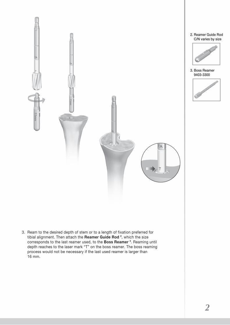
3. Ream to the desired depth of stem or to a length of fixation preferred for tibial alignment. Then attach the Reamer Guide Rod 2, which the size corresponds to the last reamer used, to the Boss Reamer 3. Reaming until depth reaches to the laser mark “T” on the boss reamer. The boss reaming process would not be necessary if the last used reamer is larger than 16 mm.
3. Boss Reamer 9403-3300
2. Reamer Guide Rod C/N varies by size

2.2 Proximal Tibial Resection
1. Attach the IM Guide Collar 5 to the Tibial IM Alignment Guide 6.
2. Slide the Tibial Resection Guide 7 onto the Tibial IM Alignment Guide 6.
3
5. IM Guide Collar 9403-2311 S 9403-2313 M 9403-2315 L
6. Tibial IM Alignment Guide 9403-2310
7. Tibial Resection Guide 9403-2321-RB Left 9403-2322-RB Right
U2 PSATM Revision Knee
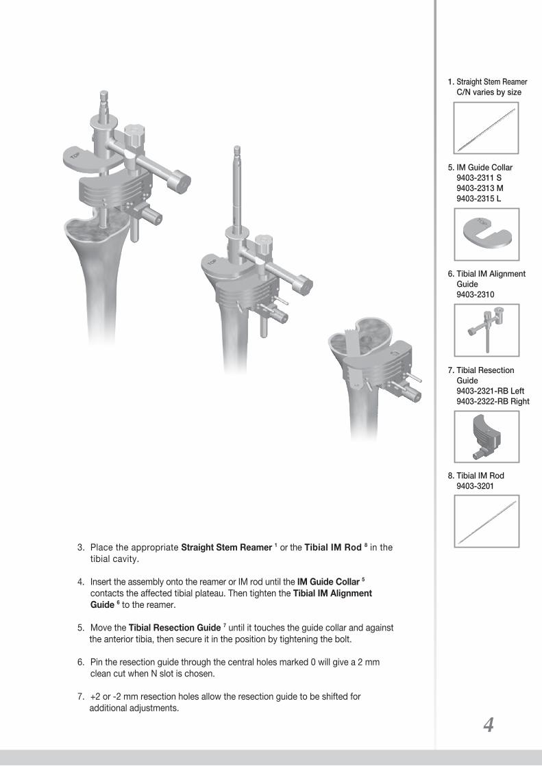
3. Place the appropriate Straight Stem Reamer 1 or the Tibial IM Rod 8 in the tibial cavity.
4. Insert the assembly onto the reamer or IM rod until the IM Guide Collar 5 contacts the affected tibial plateau. Then tighten the Tibial IM Alignment Guide 6 to the reamer.
5. Move the Tibial Resection Guide 7 until it touches the guide collar and against the anterior tibia, then secure it in the position by tightening the bolt.
6. Pin the resection guide through the central holes marked 0 will give a 2 mm clean cut when N slot is chosen.
7. +2 or -2 mm resection holes allow the resection guide to be shifted for additional adjustments.
4
1. Straight Stem Reamer C/N varies by size
5. IM Guide Collar 9403-2311 S 9403-2313 M 9403-2315 L
6. Tibial IM Alignment Guide 9403-2310
7. Tibial Resection Guide 9403-2321-RB Left 9403-2322-RB Right
8. Tibial IM Rod 9403-3201
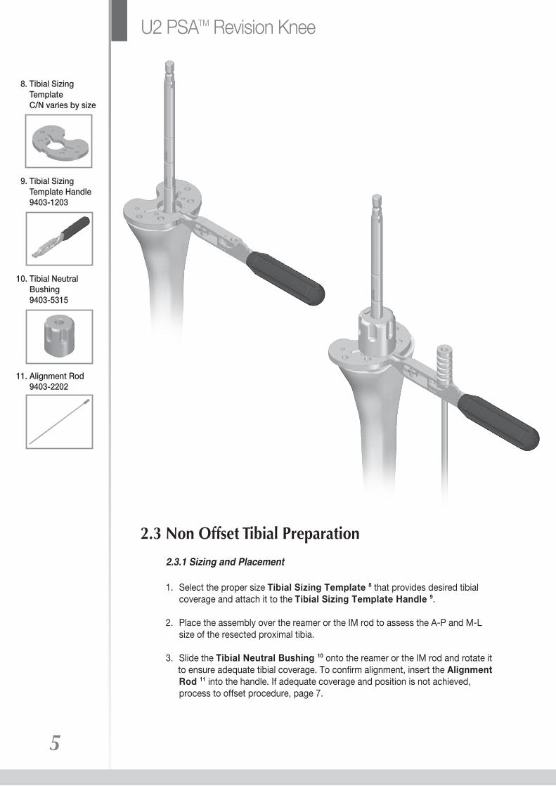
2.3.1 Sizing and Placement
1. Select the proper size Tibial Sizing Template 8 that provides desired tibial coverage and attach it to the Tibial Sizing Template Handle 9.
2. Place the assembly over the reamer or the IM rod to assess the A-P and M-L size of the resected proximal tibia.
3. Slide the Tibial Neutral Bushing 10 onto the reamer or the IM rod and rotate it to ensure adequate tibial coverage. To confirm alignment, insert the Alignment Rod 11 into the handle. If adequate coverage and position is not achieved, process to offset procedure, page 7.
5
U2 PSATM Revision Knee
2.3 Non Offset Tibial Preparation
8. Tibial Sizing Template C/N varies by size
9. Tibial Sizing Template Handle 9403-1203
10. Tibial Neutral Bushing 9403-5315
11. Alignment Rod 9403-2202
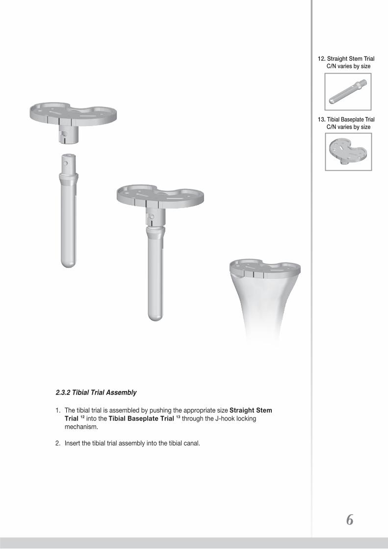
2.3.2 Tibial Trial Assembly
1. The tibial trial is assembled by pushing the appropriate size Straight Stem Trial 12 into the Tibial Baseplate Trial 13 through the J-hook locking mechanism.
2. Insert the tibial trial assembly into the tibial canal.
6
12. Straight Stem Trial C/N varies by size
13. Tibial Baseplate Trial C/N varies by size

7
U2 PSATM Revision Knee
2.4 Offset Tibial Trial Preparation
14. Tibial Offset Bushing 9403-5316 2 mm 9403-5317 4 mm
15. Offset Bushing Wrench 9403-5333
11. Alignment Rod 9403-2202
2.4.1 Offset Sizing and Placement
1. If the desired tibial coverage and adequate position was not achieved, offset procedure would be necessary.
2. Insert the 2 mm or 4 mm Tibial Offset Bushing 14 into the reamer and use the Offset Bushing Wrench 15 to rotate it until the proper tibial coverage is achieved. Use the Alignment Rod 11 to confirm alignment.
3. Make a note of the number on the offset bushing that lines to the laser mark on the Tibial Sizing Template 8. (eg. 5 o’clock position shown above)
8. Tibial Sizing Template C/N varies by size
5 o’clock direction

8
51. Tibial Stem Drill Guide 9403-2414
52. Tibial Stem Drill 9403-3314
2.4.2 Offset Tibial Canal Preparation
1. Fix the Tibial Sizing Template 8 with two pins. Assemble Tibial Stem Drill Guide 51 to the Tibial Sizing Template 8. Prepare the offset canal by applying Tibial Stem Drill 52 until the stopper attaches the drill guide.
8. Tibial Sizing Template C/N varies by size
Offset canal toward 5 o’clock direction
Original canal
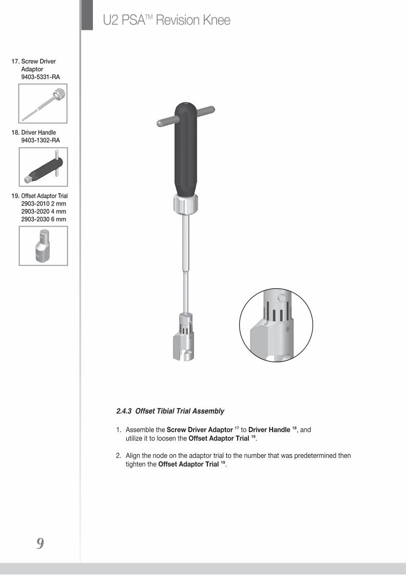
18. Driver Handle 9403-1302-RA
17. Screw Driver Adaptor 9403-5331-RA
2.4.3 Offset Tibial Trial Assembly
1. Assemble the Screw Driver Adaptor 17 to Driver Handle 18, and utilize it to loosen the Offset Adaptor Trial 19.
2. Align the node on the adaptor trial to the number that was predetermined then tighten the Offset Adaptor Trial 19.
9
U2 PSATM Revision Knee
19. Offset Adaptor Trial 2903-2010 2 mm 2903-2020 4 mm 2903-2030 6 mm
10
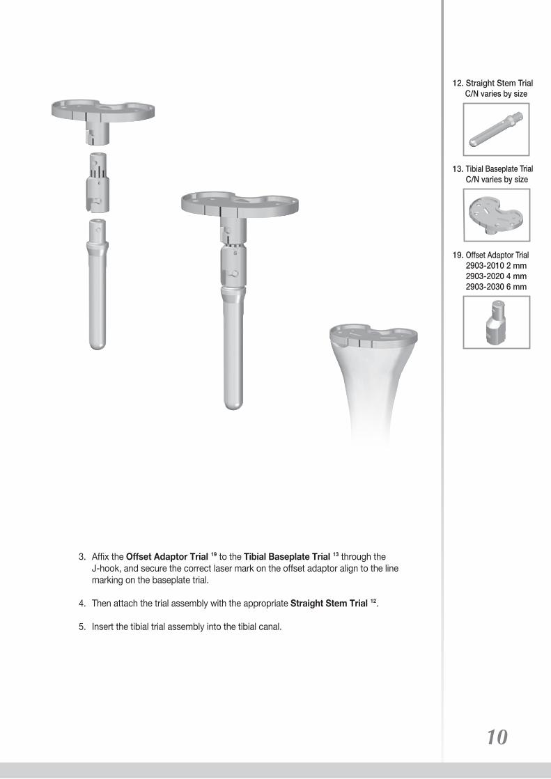
3. Affix the Offset Adaptor Trial 19 to the Tibial Baseplate Trial 13 through the J-hook, and secure the correct laser mark on the offset adaptor align to the line marking on the baseplate trial.
4. Then attach the trial assembly with the appropriate Straight Stem Trial 12.
5. Insert the tibial trial assembly into the tibial canal.
12. Straight Stem Trial C/N varies by size
13. Tibial Baseplate TrialC/N varies by size
19. Offset Adaptor Trial 2903-2010 2 mm 2903-2020 4 mm 2903-2030 6 mm
11
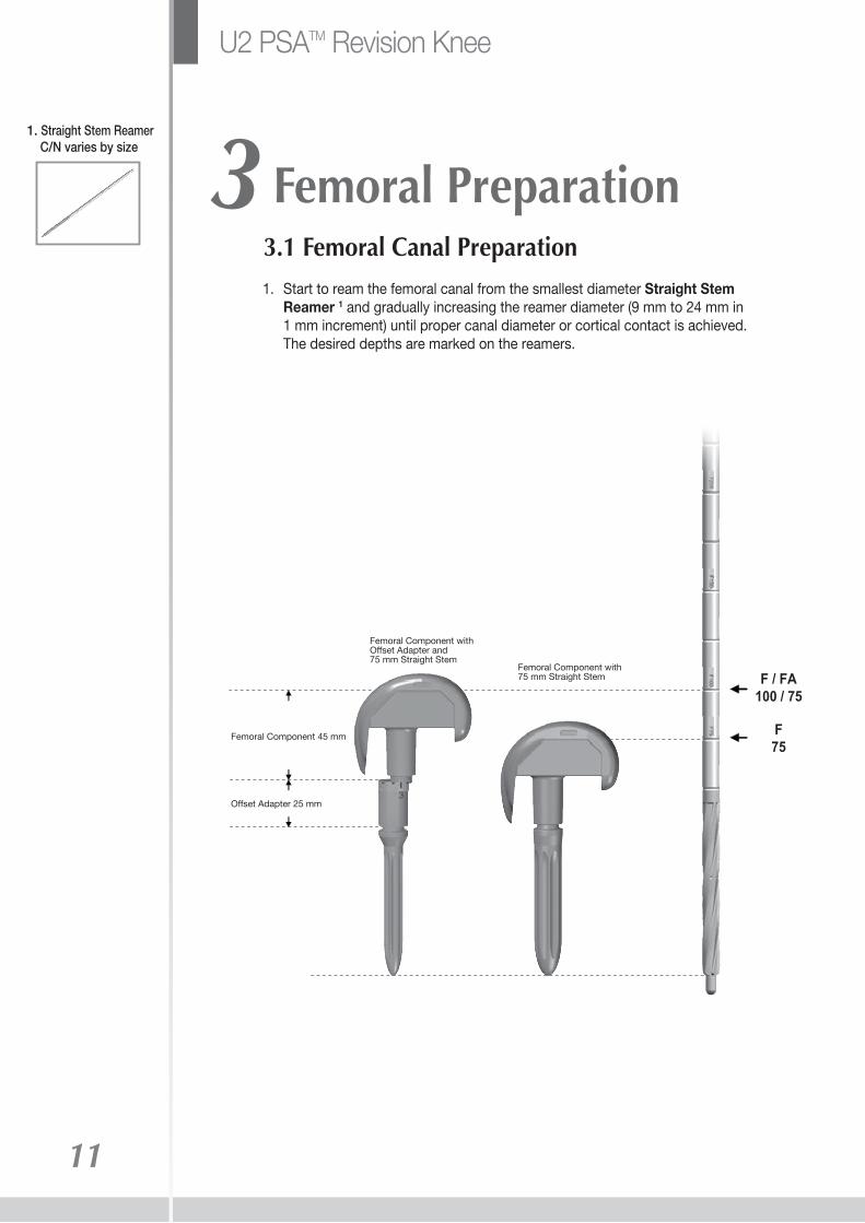
3 Femoral Preparation
1. Start to ream the femoral canal from the smallest diameter Straight Stem Reamer 1 and gradually increasing the reamer diameter (9 mm to 24 mm in 1 mm increment) until proper canal diameter or cortical contact is achieved. The desired depths are marked on the reamers.
3.1 Femoral Canal Preparation
1. Straight Stem Reamer C/N varies by size
Femoral Component withOffset Adapter and75 mm Straight Stem
Femoral Component 45 mm
Offset Adapter 25 mm
Femoral Component with75 mm Straight Stem F / FA
100 / 75
F75
U2 PSATM Revision Knee
12
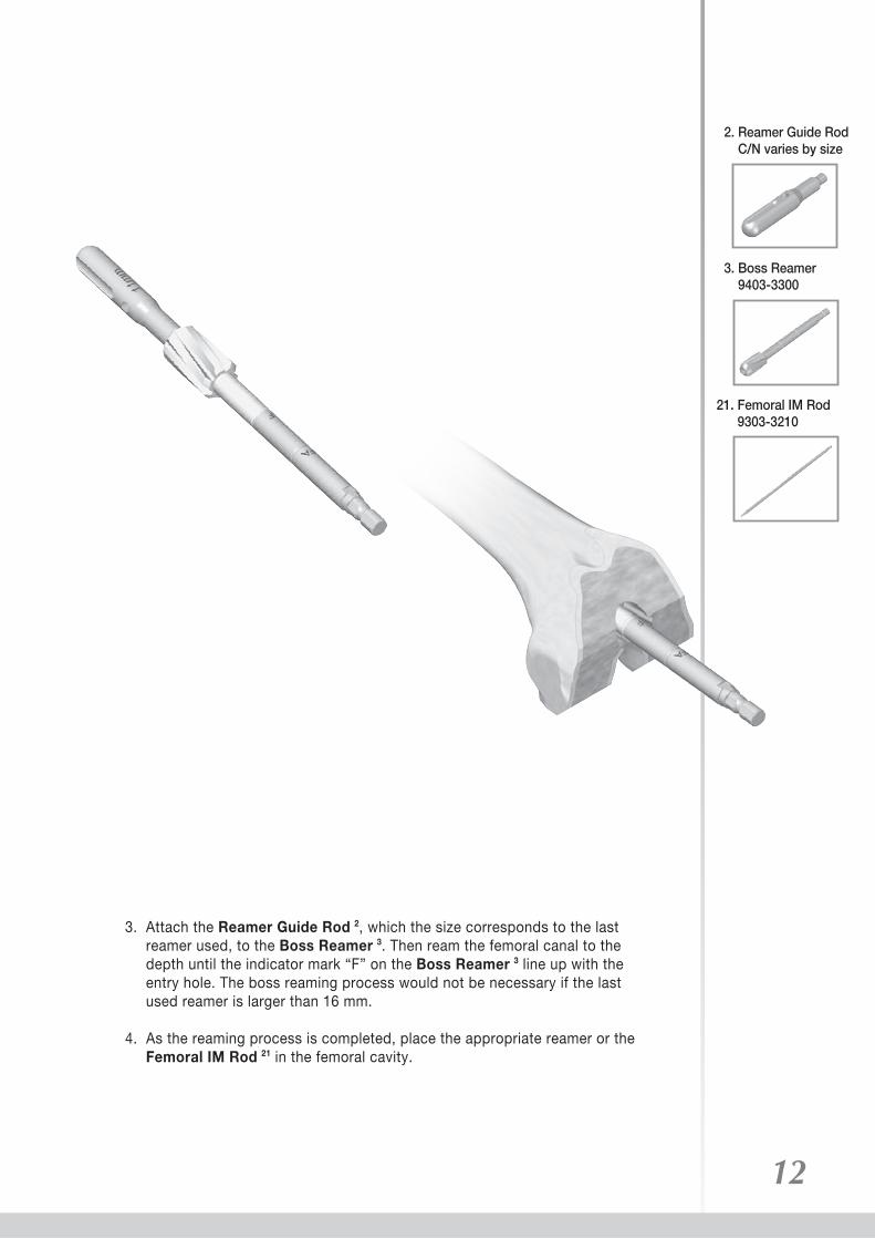
21. Femoral IM Rod 9303-3210
3. Attach the Reamer Guide Rod 2, which the size corresponds to the last reamer used, to the Boss Reamer 3. Then ream the femoral canal to the depth until the indicator mark “F” on the Boss Reamer 3 line up with the entry hole. The boss reaming process would not be necessary if the last used reamer is larger than 16 mm.
4. As the reaming process is completed, place the appropriate reamer or the Femoral IM Rod 21 in the femoral cavity.
3. Boss Reamer 9403-3300
2. Reamer Guide Rod C/N varies by size
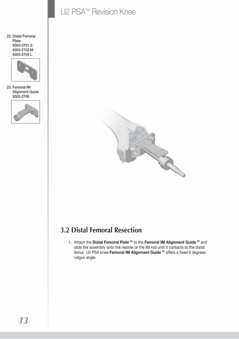
3.2 Distal Femoral Resection
1. Attach the Distal Femoral Plate 22 to the Femoral IM Alignment Guide 23 and slide the assembly onto the reamer or the IM rod until it contacts to the distal femur. U2 PSA knee Femoral IM Alignment Guide 23 offers a fixed 6 degrees valgus angle.
13
22. Distal Femoral Plate 9303-2701 S 9303-2703 M 9303-2705 L
23. Femoral IM Alignment Guide 9303-2706
U2 PSATM Revision Knee

2. Attach the Distal Femoral Alignment Guide 24 to the Distal Femoral Resection Guide 25, and then slide the assembly onto the Femoral IM Alignment Guide 23.
3. Use Pins 26 to affix the Distal Femoral Resection Guide 25. Then remove the alignment guides assembly from the IM rod or the reamer.
4. A 2mm clean cut will achieve, when resecting through the “N” slot on the Distal Femoral Resection Guide 25.
NOTE: If adjustment for the resection is needed, utilize the +2 or +4 holes to relocate the Distal Femoral Resection Guide 25 accordingly.
14
24. Distal Femoral Alignment Guide 9303-2707
25. Distal Femoral Resection Guide 9303-2708-RB
26. Pin 9303-3207
23. Femoral IM Alignment Guide 9303-2706

3.3.1 Femoral Sizing Preparation
1. Assemble the Femoral Valgus Adaptor 27 to the appropriate size Straight Stem Trial 12.
2. Insert the Femoral Valgus Adaptor 27 onto the Femoral Sizing Template 28 and depress it until it is fully engaged to the sizing template.
3. Utilize the Screw Driver Adaptor 17 that assemble to the Driver Handle 18, to tighten the adaptor to the sizing template.
Note: If the adaptor cannot be pressed down to the position, check the set screw on the side of the sizing template and release it.
15
27. Femoral Valgus Adaptor 9303-5333-RA Left 9303-5334-RA Right
28. Femoral Sizing Template C/N varies by size
3.3 Non Offset Femoral Sizing and Placement
12. Straight Stem Trial C/N varies by size
18. Driver Handle 9403-1302-RA
17. Screw Driver Adaptor 9403-5331-RA
U2 PSATM Revision Knee

4. Insert the femoral sizing assembly into the canal and assess proper A-P / M-L size and position in relation to the femur.
16
17
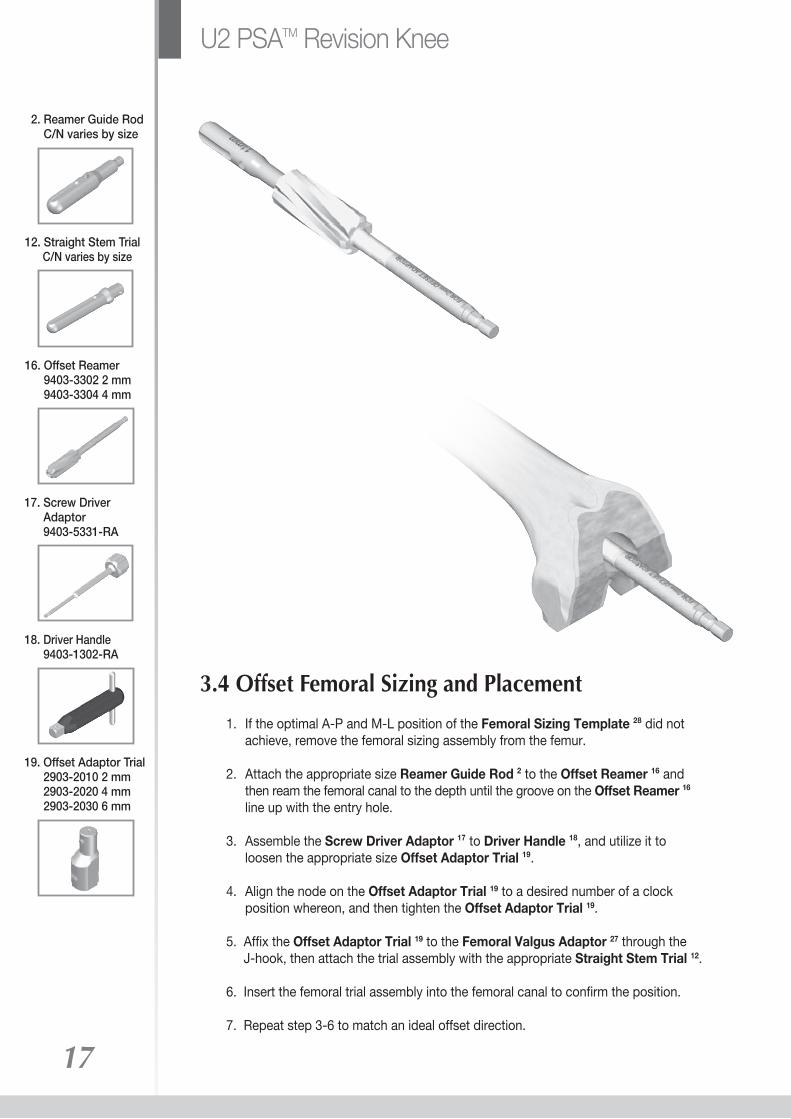
3.4 Offset Femoral Sizing and Placement
12. Straight Stem Trial C/N varies by size
2. Reamer Guide Rod C/N varies by size
16. Offset Reamer 9403-3302 2 mm 9403-3304 4 mm
18. Driver Handle 9403-1302-RA
19. Offset Adaptor Trial 2903-2010 2 mm 2903-2020 4 mm 2903-2030 6 mm
1. If the optimal A-P and M-L position of the Femoral Sizing Template 28 did not achieve, remove the femoral sizing assembly from the femur.
2. Attach the appropriate size Reamer Guide Rod 2 to the Offset Reamer 16 and then ream the femoral canal to the depth until the groove on the Offset Reamer 16 line up with the entry hole. 3. Assemble the Screw Driver Adaptor 17 to Driver Handle 18, and utilize it to loosen the appropriate size Offset Adaptor Trial 19.
4. Align the node on the Offset Adaptor Trial 19 to a desired number of a clock position whereon, and then tighten the Offset Adaptor Trial 19.
5. Affix the Offset Adaptor Trial 19 to the Femoral Valgus Adaptor 27 through the J-hook, then attach the trial assembly with the appropriate Straight Stem Trial 12.
6. Insert the femoral trial assembly into the femoral canal to confirm the position.
7. Repeat step 3-6 to match an ideal offset direction.
17. Screw Driver Adaptor 9403-5331-RA
U2 PSATM Revision Knee

18
1. Once A-P and M-L position of the femoral sizing assembly has determined,leaving femoral sizing assembly in the femur, and placing the proper size Tibial Spacer Base 29 on the tibial baseplate assembly with the appropriate thickness Tibial Spacer 30.
2. Perform the joint line evaluation. If the femoral sizing assembly did not contact to the distal end of the femur during the evaluation, the Femoral Distal Spacer 31
can be utilized as temporary augment.
3. After restoring appropriate joint line, establish stability in extension and flexion gap.
3.5 Joint Line Evaluation and Flexion/Extension Gap Balancing
28. Femoral Sizing Template C/N varies by size
29. Tibial Spacer Base C/N varies by size
30. Tibial Spacer C/N varies by size
31. Femoral Distal Spacer 9303-5202 2 mm 9303-5204 4 mm 9303-5206 6 mm 9303-5208 8 mm
27. Femoral Valgus Adaptor 9303-5333-RA Left 9303-5334-RA Right
19
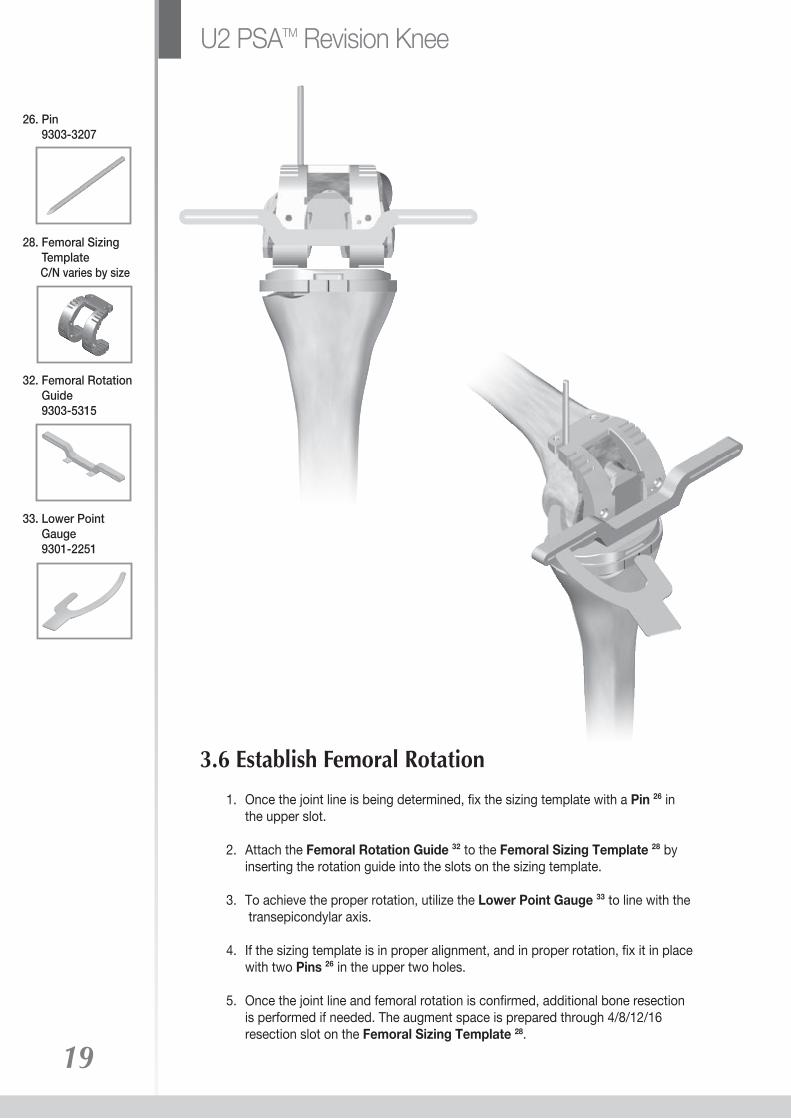
1. Once the joint line is being determined, fix the sizing template with a Pin 26 in the upper slot.
2. Attach the Femoral Rotation Guide 32 to the Femoral Sizing Template 28 by inserting the rotation guide into the slots on the sizing template.
3. To achieve the proper rotation, utilize the Lower Point Gauge 33 to line with the transepicondylar axis.
4. If the sizing template is in proper alignment, and in proper rotation, fix it in place with two Pins 26 in the upper two holes.
5. Once the joint line and femoral rotation is confirmed, additional bone resection is performed if needed. The augment space is prepared through 4/8/12/16 resection slot on the Femoral Sizing Template 28.
3.6 Establish Femoral Rotation
28. Femoral Sizing Template C/N varies by size
26. Pin 9303-3207
33. Lower Point Gauge 9301-2251
32. Femoral Rotation Guide 9303-5315
U2 PSATM Revision Knee

20
1. Use the saw blade to mark the femoral box location and then remove the femoral sizing assembly and pins.
2. Then complete the resection.
3.7 Femoral Box Preparation

21
34. Femoral Posterior Augment Trial C/N varies by size
35. Femoral Distal Augment Trial C/N varies by size
4 Final Trial Reduction
1. Attach the appropriate Femoral Posterior Augment Trial 34, and/or the Femoral Distal Augment Trial 35 to the proper Femoral Trial 36 by snapping into place.
2. Assemble the Femoral Trial 36 to the Straight Stem Trial 12 and the Offset Adaptor Trial 19, if desired.
4.1 Femoral Trial Preparation19. Offset Adaptor Trial 2903-2010 2 mm 2903-2020 4 mm 2903-2030 6 mm
12. Straight Stem Trial C/N varies by size
36. Femoral Trial C/N varies by size
U2 PSATM Revision Knee
22
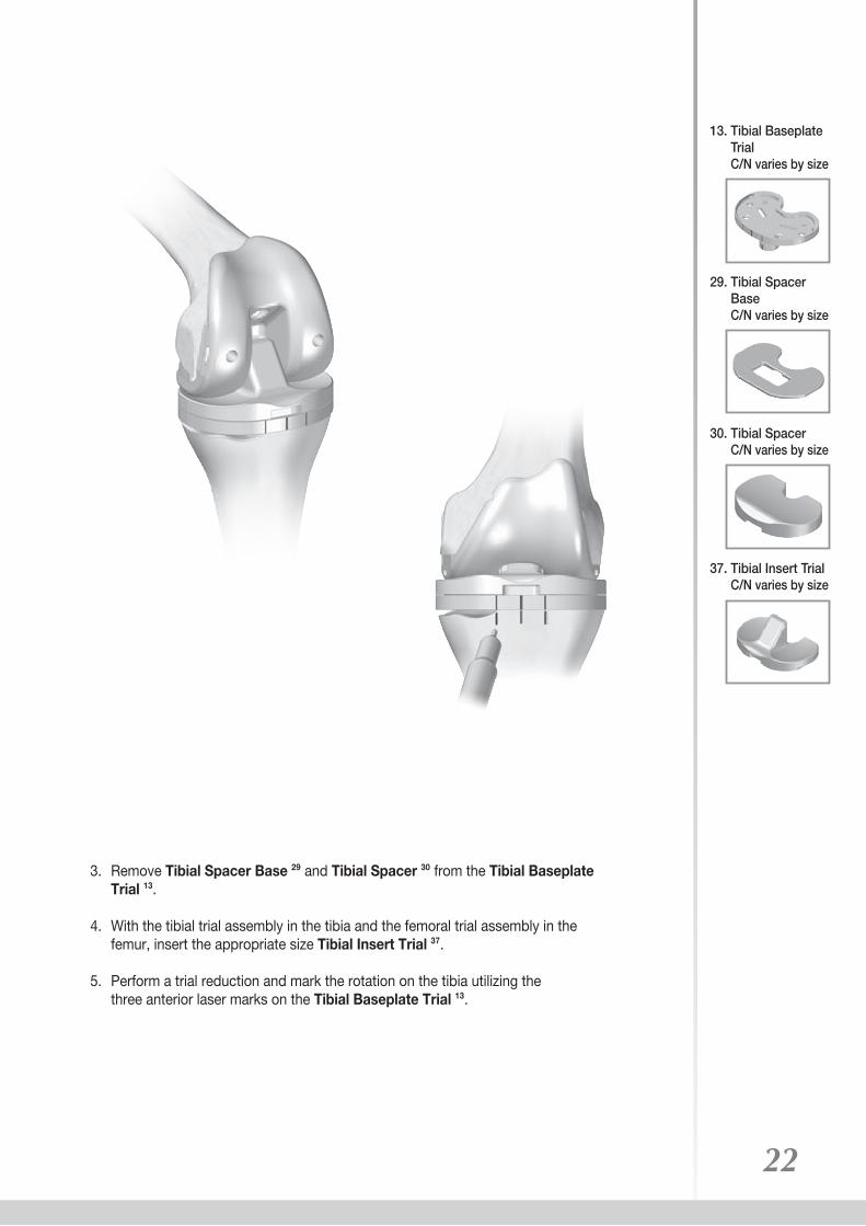
3. Remove Tibial Spacer Base 29 and Tibial Spacer 30 from the Tibial Baseplate Trial 13.
4. With the tibial trial assembly in the tibia and the femoral trial assembly in the femur, insert the appropriate size Tibial Insert Trial 37.
5. Perform a trial reduction and mark the rotation on the tibia utilizing the three anterior laser marks on the Tibial Baseplate Trial 13.
37. Tibial Insert Trial C/N varies by size
13. Tibial Baseplate Trial C/N varies by size
29. Tibial Spacer Base C/N varies by size
30. Tibial Spacer C/N varies by size

4.2 Final Tibial Preparation 4.2.1 Tibial Augment Resection
1. If the tibial augments are needed, use two Pins 26 through the Tibial Baseplate Trial 13 and pin the baseplate trial into the proximal tibia to lock the rotational orientation.
2. Remove the tibial trial, and place the proper Tibial Sizing Template 8 on the tibial plateau through the pins. Make sure the laser marks on the sizing template align to the marks on the anterior tibia. Then attach the Tibial Alignment Sleeve 38 on the top of the template.
3. Reposition the tibial resection assembly and fix it with two Pins 26 to the anterior tibia.
4. Remove the template/sleeve/alignment guide and leave the Tibial Resection Guide 7 in place and make the appropriate resections. 5, 10, and 15 mm tibial augments are available for bone lost cases. 23
38. Tibial Alignment Sleeve 9403-2316
8. Tibial Sizing Template C/N varies by size
7. Tibial Resection Guide 9403-2321-RB Left 9403-2322-RB Right
26. Pin 9303-3207
13. Tibial Baseplate Trial C/N varies by size
U2 PSATM Revision Knee
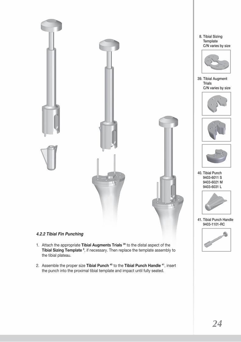
4.2.2 Tibial Fin Punching
1. Attach the appropriate Tibial Augments Trials 39 to the distal aspect of the Tibial Sizing Template 8, if necessary. Then replace the template assembly to the tibial plateau.
2. Assemble the proper size Tibial Punch 40 to the Tibial Punch Handle 41, insert the punch into the proximal tibial template and impact until fully seated.
24
40. Tibial Punch 9403-6011 S 9403-6021 M 9403-6031 L
41. Tibial Punch Handle 9403-1101-RC
8. Tibial Sizing Template C/N varies by size
39. Tibial Augment Trials C/N varies by size

4.2.3 Final Trial Reduction
1. Assemble the appropriate Tibial Baseplate Trial 13, Straight Stem Trial 12, Tibial Augment Trial 39, and/or Offset Adaptor Trial 19 for which the tibia has been prepared.
2. Insert the final assembly into the tibia and place the proper Tibial Insert Trial 37.
3. Check the range of motion, joint stability and any necessary soft tissue releases.
25
19. Offset Adaptor Trial 2903-2010 2 mm 2903-2020 4 mm 2903-2030 6 mm
12. Straight Stem Trial C/N varies by size
13. Tibial Baseplate Trial C/N varies by size
37. Tibial Insert Trial C/N varies by size
39. Tibial Augment Trial C/N varies by size
U2 PSATM Revision Knee

DevotedOrthopedics
to
27
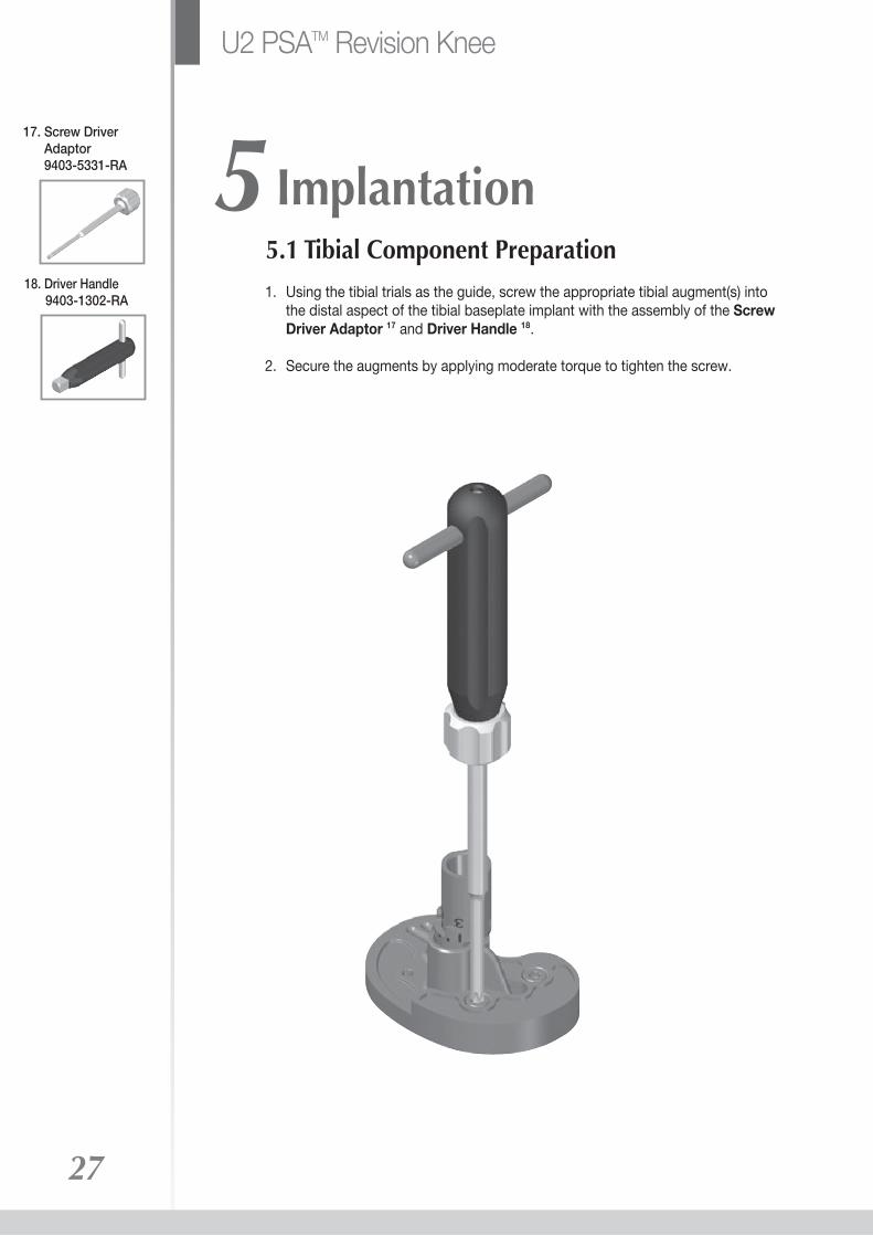
5 Implantation
1. Using the tibial trials as the guide, screw the appropriate tibial augment(s) into the distal aspect of the tibial baseplate implant with the assembly of the Screw Driver Adaptor 17 and Driver Handle 18.
2. Secure the augments by applying moderate torque to tighten the screw.
5.1 Tibial Component Preparation 18. Driver Handle 9403-1302-RA
17. Screw Driver Adaptor 9403-5331-RA
U2 PSATM Revision Knee
28
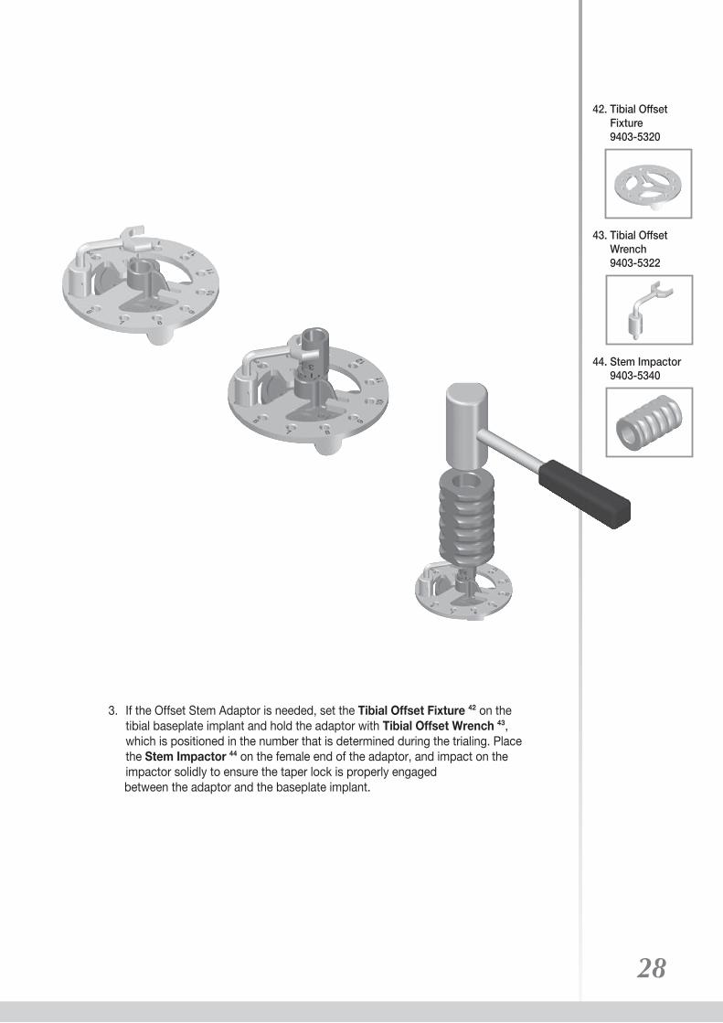
3. If the Offset Stem Adaptor is needed, set the Tibial Offset Fixture 42 on the tibial baseplate implant and hold the adaptor with Tibial Offset Wrench 43, which is positioned in the number that is determined during the trialing. Place the Stem Impactor 44 on the female end of the adaptor, and impact on the impactor solidly to ensure the taper lock is properly engaged between the adaptor and the baseplate implant.
43. Tibial Offset Wrench 9403-5322
42. Tibial Offset Fixture 9403-5320
44. Stem Impactor 9403-5340

4. Select the appropriate length and diameter stem that was used for the tibial trial.
5. Insert the stem extension implant into the offset adaptor and/or the tibial baseplate implant, and protect the stem by placing the Stem Impactor 44 on the tip of the stem.
6. Impact on the impactor solidly to ensure the taper lock is properly engaged.
29
44. Stem Impactor 9403-5340
U2 PSATM Revision Knee
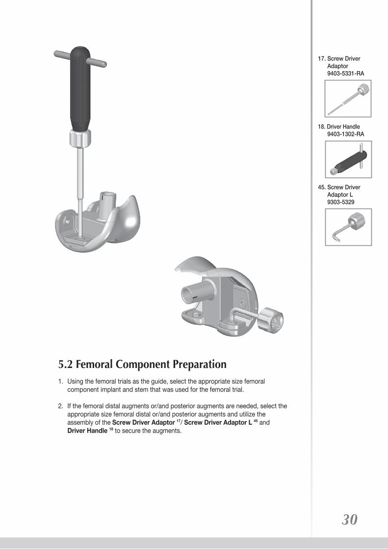
1. Using the femoral trials as the guide, select the appropriate size femoral component implant and stem that was used for the femoral trial.
2. If the femoral distal augments or/and posterior augments are needed, select the appropriate size femoral distal or/and posterior augments and utilize the assembly of the Screw Driver Adaptor 17/ Screw Driver Adaptor L 45 and Driver Handle 18 to secure the augments.
5.2 Femoral Component Preparation
30
45. Screw Driver Adaptor L 9303-5329
18. Driver Handle 9403-1302-RA
17. Screw Driver Adaptor 9403-5331-RA
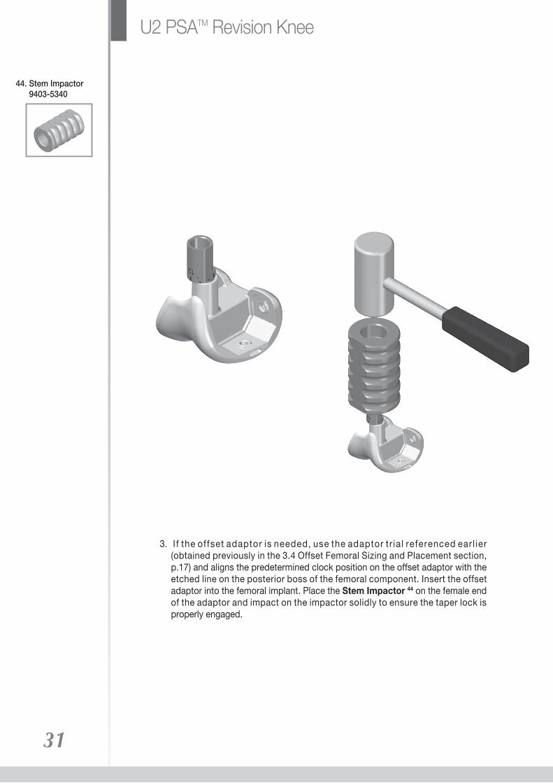
3. I f the offset adaptor is needed, use the adaptor tr ial referenced earl ier (obtained previously in the 3.4 Offset Femoral Sizing and Placement section, p.17) and aligns the predetermined clock position on the offset adaptor with the etched line on the posterior boss of the femoral component. Insert the offset adaptor into the femoral implant. Place the Stem Impactor 44 on the female end of the adaptor and impact on the impactor solidly to ensure the taper lock is properly engaged.
31
44. Stem Impactor 9403-5340
U2 PSATM Revision Knee

4. Select the appropriate length and diameter stem that was used for the femoral trial.
5. Insert the stem extension implant into the offset adaptor and/or femoral component implant, and protect the stem by placing the Stem Impactor 44 on the tip of the stem.
6. Impact on the impactor solidly two times to ensure the taper lock is properly engaged.
7. After the stem has been impacted into the femoral component, insert the femoral screw into the intercondylar hole. 8. Utilize the assembly of the Screw Driver Adaptor 17 and Driver Handle 18, then apply moderate torque to tighten the femoral screw to the femoral component and the stem/offset adaptor.
32
18. Driver Handle 9403-1302-RA
17. Screw Driver Adaptor 9403-5331-RA
44. Stem Impactor 9403-5340
33
46. Tibial Baseplate Driver 9403-5101-RC
47. Tibial Baseplate Impactor 9403-5102-RF
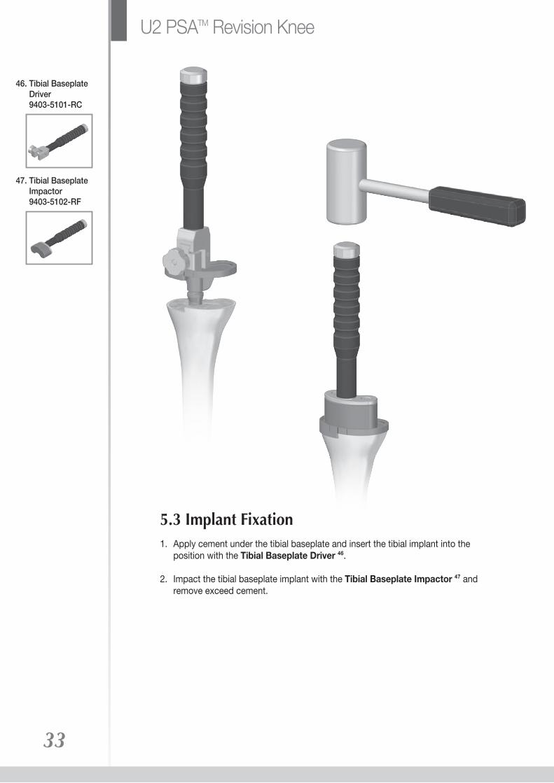
1. Apply cement under the tibial baseplate and insert the tibial implant into the position with the Tibial Baseplate Driver 46.
2. Impact the tibial baseplate implant with the Tibial Baseplate Impactor 47 and remove exceed cement.
5.3 Implant Fixation
U2 PSATM Revision Knee

3. Place cement onto the surface of the femoral component implant and insert the implant into the position with the Femoral Driver 48.
4. Impact the implant with the Femoral Impactor 49 and remove exceed cement.
34
49. Femoral Impactor 9303-5103-RB
48. Femoral Driver 9303-5110

5. Place the appropriate size tibial insert on the tibial baseplate and use the Universal Impactor 50 to fully seat the insert.
35
50. Universal Impactor 9303-5119-RB
U2 PSATM Revision Knee
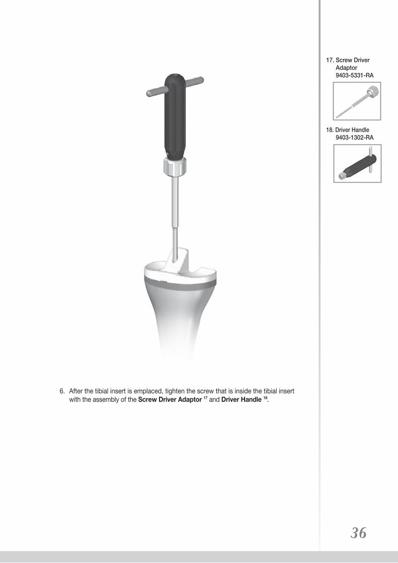
6. After the tibial insert is emplaced, tighten the screw that is inside the tibial insert with the assembly of the Screw Driver Adaptor 17 and Driver Handle 18.
36
18. Driver Handle 9403-1302-RA
17. Screw Driver Adaptor 9403-5331-RA

Number Description
U2 PSATM Component
Femoral Component
Tibial Baseplate
Tibial Insert Assembly
2103 - 5110 Left #12103 - 5120 Left #22103 - 5130 Left #32103 - 5140 Left #42103 - 5150 Left #52103 - 5160 Left #6
Number Description
Number Description
2103 - 5210 Right #12103 - 5220 Right #22103 - 5230 Right #32103 - 5240 Right #42103 - 5250 Right #52103 - 5260 Right #6
Number Description
2203 - 5210 #12203 - 5220 #22203 - 5230 #3
2203 - 5240 #42203 - 5250 #52203 - 5260 #6
Number DescriptionNumber Description
2303 - 5011 #1 9 mm2303 - 5012 #1 11 mm2303 - 5013 #1 13 mm2303 - 5014 #1 15 mm2303 - 5015 #1 18 mm2303 - 5016 #1 21 mm2303 - 5017 #1 25 mm2303 - 5018 #1 30 mm
2303 - 5021 #2 9 mm2303 - 5022 #2 11 mm2303 - 5023 #2 13 mm2303 - 5024 #2 15 mm2303 - 5025 #2 18 mm2303 - 5026 #2 21 mm2303 - 5027 #2 25 mm2303 - 5028 #2 30 mm
2303 - 5031 #3 9 mm2303 - 5032 #3 11 mm2303 - 5033 #3 13 mm2303 - 5034 #3 15 mm2303 - 5035 #3 18 mm2303 - 5036 #3 21 mm2303 - 5037 #3 25 mm2303 - 5038 #3 30 mm
2303 - 5041 #4 9 mm2303 - 5042 #4 11 mm2303 - 5043 #4 13 mm2303 - 5044 #4 15 mm2303 - 5045 #4 18 mm2303 - 5046 #4 21 mm2303 - 5047 #4 25 mm2303 - 5048 #4 30 mm
2303 - 5051 #5 9 mm2303 - 5052 #5 11 mm2303 - 5053 #5 13 mm2303 - 5054 #5 15 mm2303 - 5055 #5 18 mm2303 - 5056 #5 21 mm2303 - 5057 #5 25 mm2303 - 5058 #5 30 mm
2303 - 5061 #6 9 mm2303 - 5062 #6 11 mm2303 - 5063 #6 13 mm2303 - 5064 #6 15 mm2303 - 5065 #6 18 mm2303 - 5066 #6 21 mm2303 - 5067 #6 25 mm2303 - 5068 #6 30 mm37
Special Order Items

U2 PSATM Component
Femoral Augment Assembly
38
2603 - 5011 Posterior #1 4 mm2603 - 5021 Posterior #2 4 mm2603 - 5031 Posterior #3 4 mm2603 - 5041 Posterior #4 4 mm2603 - 5051 Posterior #5 4 mm2603 - 5061 Posterior #6 4 mm2603 - 5012 Posterior #1 8 mm2603 - 5022 Posterior #2 8 mm2603 - 5032 Posterior #3 8 mm2603 - 5042 Posterior #4 8 mm2603 - 5052 Posterior #5 8 mm2603 - 5062 Posterior #6 8 mm 2603 - 5111 Distal L.M. / R.L. #1 4 mm2603 - 5121 Distal L.M. / R.L. #2 4 mm2603 - 5131 Distal L.M. / R.L. #3 4 mm2603 - 5141 Distal L.M. / R.L. #4 4 mm2603 - 5151 Distal L.M. / R.L. #5 4 mm2603 - 5161 Distal L.M. / R.L. #6 4 mm2603 - 5112 Distal L.M. / R.L. #1 8 mm2603 - 5122 Distal L.M. / R.L. #2 8 mm2603 - 5132 Distal L.M. / R.L. #3 8 mm2603 - 5142 Distal L.M. / R.L. #4 8 mm2603 - 5152 Distal L.M. / R.L. #5 8 mm2603 - 5162 Distal L.M. / R.L. #6 8 mm2603 - 5211 Distal L.L. / R.M. #1 4 mm2603 - 5221 Distal L.L. / R.M. #2 4 mm2603 - 5231 Distal L.L. / R.M. #3 4 mm2603 - 5241 Distal L.L. / R.M. #4 4 mm2603 - 5251 Distal L.L. / R.M. #5 4 mm2603 - 5261 Distal L.L. / R.M. #6 4 mm2603 - 5212 Distal L.L. / R.M. #1 8 mm2603 - 5222 Distal L.L. / R.M. #2 8 mm2603 - 5232 Distal L.L. / R.M. #3 8 mm2603 - 5242 Distal L.L. / R.M. #4 8 mm2603 - 5252 Distal L.L. / R.M. #5 8 mm2603 - 5262 Distal L.L. / R.M. #6 8 mm 2603 - 5313 Distal #1 12 mm2603 - 5323 Distal #2 12 mm2603 - 5333 Distal #3 12 mm2603 - 5343 Distal #4 12 mm2603 - 5353 Distal #5 12 mm2603 - 5363 Distal #6 12 mm2603 - 5314 Distal #1 16 mm2603 - 5324 Distal #2 16 mm2603 - 5334 Distal #3 16 mm2603 - 5344 Distal #4 16 mm2603 - 5354 Distal #5 16 mm2603 - 5364 Distal #6 16 mm
Number Description
U2 PSATM Component
Straight Stem
39
Number Description Number Description
Special Order Items
2703 - 5003 Ø 14 x 30 mm
2703 - 5011 Ø 10 x 75 mm2703 - 5012 Ø 12 x 75 mm2703 - 5013 Ø 14 x 75 mm2703 - 5014 Ø 16 x 75 mm2703 - 5015 Ø 18 x 75 mm2703 - 5016 Ø 20 x 75 mm
2703 - 5051 Ø 10 x 150 mm2703 - 5052 Ø 12 x 150 mm2703 - 5053 Ø 14 x 150 mm2703 - 5054 Ø 16 x 150 mm2703 - 5055 Ø 18 x 150 mm2703 - 5056 Ø 20 x 150 mm2703 - 5057 Ø 22 x 150 mm
2703 - 5021 Ø 10 x 100 mm2703 - 5022 Ø 12 x 100 mm2703 - 5023 Ø 14 x 100 mm2703 - 5024 Ø 16 x 100 mm2703 - 5025 Ø 18 x 100 mm2703 - 5026 Ø 20 x 100 mm
2703 - 5061 Ø 10 x 200 mm2703 - 5062 Ø 12 x 200 mm2703 - 5063 Ø 14 x 200 mm2703 - 5064 Ø 16 x 200 mm2703 - 5065 Ø 18 x 200 mm2703 - 5066 Ø 20 x 200 mm2703 - 5067 Ø 22 x 200 mm
Curved StemNumber Description
2703 - 5031 Ø 10 x 150 mm2703 - 5032 Ø 12 x 150 mm2703 - 5033 Ø 14 x 150 mm2703 - 5034 Ø 16 x 150 mm2703 - 5035 Ø 18 x 150 mm2703 - 5036 Ø 20 x 150 mm2703 - 5037 Ø 22 x 150 mm
2703 - 5041 Ø 10 x 200 mm2703 - 5042 Ø 12 x 200 mm2703 - 5043 Ø 14 x 200 mm2703 - 5044 Ø 16 x 200 mm2703 - 5045 Ø 18 x 200 mm2703 - 5046 Ø 20 x 200 mm2703 - 5047 Ø 22 x 200 mm

U2 PSATM Component
40
Tibial AugmentNumber Description
2803 - 5211 #1 5 mm2803 - 5221 #2 5 mm2803 - 5231 #3 5 mm2803 - 5241 #4 5 mm2803 - 5251 #5 5 mm2803 - 5261 #6 5 mm2803 - 5212 #1 10 mm2803 - 5222 #2 10 mm2803 - 5232 #3 10 mm2803 - 5242 #4 10 mm2803 - 5252 #5 10 mm2803 - 5262 #6 10 mm 2803 - 5113 L.M. / R.L. #1 15 mm2803 - 5123 L.M. / R.L. #2 15 mm2803 - 5133 L.M. / R.L. #3 15 mm2803 - 5143 L.M. / R.L. #4 15 mm2803 - 5153 L.M. / R.L. #5 15 mm2803 - 5163 L.M. / R.L. #6 15 mm2803 - 5213 R.M. / L.L. #1 15 mm2803 - 5223 R.M. / L.L. #2 15 mm2803 - 5233 R.M. / L.L. #3 15 mm2803 - 5243 R.M. / L.L. #4 15 mm2803 - 5253 R.M. / L.L. #5 15 mm2803 - 5263 R.M. / L.L. #6 15 mm
Femoral ScrewNumber Description
2903 - 1014 M5 x 14 mm
Offset Stem AdaptorNumber Description
2903 - 3010 2 mm2903 - 3020 4 mm2903 - 3030 6 mm

2103 - 6110 left #1
2103 - 6120 left #2
2103 - 6130 left #3
2103 - 6140 left #4
2103 - 6150 left #5
2103 - 6160 left #6
2103 - 6210 right #1
2103 - 6220 right #2
2103 - 6230 right #3
2103 - 6240 right #4
2103 - 6250 right #5
2103 - 6260 right #6
Number Description
2203 - 6010 #1
2203 - 6020 #2
2203 - 6030 #3
2203 - 6040 #4
2203 - 6050 #5
2203 - 6060 #6
Number Description
41
U2 PSATM Instrument
Femoral Trial
Tibial Baseplate Trial

42
2303 - 6011 #1 9 mm2303 - 6012 #1 11 mm2303 - 6013 #1 13 mm2303 - 6014 #1 15 mm2303 - 6015 #1 18 mm2303 - 6016 #1 21 mm2303 - 6017 #1 25 mm2303 - 6018 #1 30 mm
2303 - 6021 #2 9 mm2303 - 6022 #2 11 mm2303 - 6023 #2 13 mm2303 - 6024 #2 15 mm2303 - 6025 #2 18 mm2303 - 6026 #2 21 mm2303 - 6027 #2 25 mm2303 - 6028 #2 30 mm
2303 - 6031 #3 9 mm2303 - 6032 #3 11 mm2303 - 6033 #3 13 mm2303 - 6034 #3 15 mm2303 - 6035 #3 18 mm2303 - 6036 #3 21 mm2303 - 6037 #3 25 mm2303 - 6038 #3 30 mm
Special Optional Items
Number Description
2303 - 6041 #4 9 mm2303 - 6042 #4 11 mm2303 - 6043 #4 13 mm2303 - 6044 #4 15 mm2303 - 6045 #4 18 mm2303 - 6046 #4 21 mm2303 - 6047 #4 25 mm2303 - 6048 #4 30 mm
2303 - 6051 #5 9 mm2303 - 6052 #5 11 mm2303 - 6053 #5 13 mm2303 - 6054 #5 15 mm2303 - 6055 #5 18 mm2303 - 6056 #5 21 mm2303 - 6057 #5 25 mm2303 - 6058 #5 30 mm
2303 - 6061 #6 9 mm2303 - 6062 #6 11 mm2303 - 6063 #6 13 mm2303 - 6064 #6 15 mm2303 - 6065 #6 18 mm2303 - 6066 #6 21 mm2303 - 6067 #6 25 mm2303 - 6068 #6 30 mm
Number Description
U2 PSATM Instrument
Tibial Insert Trial
2603 - 6011 #1 4 mm2603 - 6021 #2 4 mm2603 - 6031 #3 4 mm2603 - 6041 #4 4 mm2603 - 6051 #5 4 mm2603 - 6061 #6 4 mm
2603 - 6012 #1 8 mm2603 - 6022 #2 8 mm2603 - 6032 #3 8 mm2603 - 6042 #4 8 mm2603 - 6052 #5 8 mm2603 - 6062 #6 8 mm
Number Description
Femoral Posterior Augment Trial
Special Order Items
Femoral Distal Augment Trial
43
2603 - 6111 L.M. / R.L. #1 4 mm2603 - 6121 L.M. / R.L. #2 4 mm2603 - 6131 L.M. / R.L. #3 4 mm2603 - 6141 L.M. / R.L. #4 4 mm2603 - 6151 L.M. / R.L. #5 4 mm2603 - 6161 L.M. / R.L. #6 4 mm
2603 - 6112 L.M. / R.L. #1 8 mm2603 - 6122 L.M. / R.L. #2 8 mm2603 - 6132 L.M. / R.L. #3 8 mm2603 - 6142 L.M. / R.L. #4 8 mm2603 - 6152 L.M. / R.L. #5 8 mm2603 - 6162 L.M. / R.L. #6 8 mm
2603 - 6211 R.M. / L.L. #1 4 mm2603 - 6221 R.M. / L.L. #2 4 mm2603 - 6231 R.M. / L.L. #3 4 mm2603 - 6241 R.M. / L.L. #4 4 mm2603 - 6251 R.M. / L.L. #5 4 mm2603 - 6261 R.M. / L.L. #6 4 mm
2603 - 6212 R.M. / L.L. #1 8 mm2603 - 6222 R.M. / L.L. #2 8 mm2603 - 6232 R.M. / L.L. #3 8 mm2603 - 6242 R.M. / L.L. #4 8 mm2603 - 6252 R.M. / L.L. #5 8 mm2603 - 6262 R.M. / L.L. #6 8 mm
2603 - 6313 #1 12 mm2603 - 6323 #2 12 mm2603 - 6333 #3 12 mm2603 - 6343 #4 12 mm2603 - 6353 #5 12 mm2603 - 6363 #6 12 mm
2603 - 6314 #1 16 mm2603 - 6324 #2 16 mm2603 - 6334 #3 16 mm2603 - 6344 #4 16 mm2603 - 6354 #5 16 mm2603 - 6364 #6 16 mm
Number Description
U2 PSATM Instrument
U2 PSATM Instrument
Straight Stem TrialNumber Description
44
Special Order Items
2703 - 6003 Ø 14 x 30 mm 2703 - 6011 Ø 10 x 75 mm2703 - 6012 Ø 12 x 75 mm2703 - 6013 Ø 14 x 75 mm2703 - 6014 Ø 16 x 75 mm2703 - 6015 Ø 18 x 75 mm2703 - 6016 Ø 20 x 75 mm 2703 - 6021 Ø 10 x 100 mm2703 - 6022 Ø 12 x 100 mm2703 - 6023 Ø 14 x 100 mm2703 - 6024 Ø 16 x 100 mm2703 - 6025 Ø 18 x 100 mm2703 - 6026 Ø 20 x 100 mm 2703 - 6051 Ø 10 x 150 mm2703 - 6052 Ø 12 x 150 mm2703 - 6053 Ø 14 x 150 mm2703 - 6054 Ø 16 x 150 mm2703 - 6055 Ø 18 x 150 mm2703 - 6056 Ø 20 x 150 mm2703 - 6057 Ø 22 x 150 mm2703 - 6058 Ø 24 x 150 mm 2703 - 6061 Ø 10 x 200 mm2703 - 6062 Ø 12 x 200 mm2703 - 6063 Ø 14 x 200 mm2703 - 6064 Ø 16 x 200 mm2703 - 6065 Ø 18 x 200 mm2703 - 6066 Ø 20 x 200 mm2703 - 6067 Ø 22 x 200 mm2703 - 6068 Ø 24 x 200 mm
Number Description
45
2703 - 6031 Ø 10 x 150 mm2703 - 6032 Ø 12 x 150 mm2703 - 6033 Ø 14 x 150 mm2703 - 6034 Ø 16 x 150 mm2703 - 6035 Ø 18 x 150 mm2703 - 6036 Ø 20 x 150 mm2703 - 6037 Ø 22 x 150 mm2703 - 6038 Ø 24 x 150 mm 2703 - 6041 Ø 10 x 200 mm2703 - 6042 Ø 12 x 200 mm2703 - 6043 Ø 14 x 200 mm2703 - 6044 Ø 16 x 200 mm2703 - 6045 Ø 18 x 200 mm2703 - 6046 Ø 20 x 200 mm2703 - 6047 Ø 22 x 200 mm2703 - 6048 Ø 24 x 200 mm
U2 PSATM Instrument
Curved Stem Trial
Number Description
2903 - 2010 2 mm 2903 - 2020 4 mm2903 - 2030 6 mm
Offset Adaptor Trial
Special Order Items

Number Description2803 - 6111 left #1 5 mm2803 - 6121 left #2 5 mm2803 - 6131 left #3 5 mm2803 - 6141 left #4 5 mm2803 - 6151 left #5 5 mm2803 - 6161 left #6 5 mm
2803 - 6112 left #1 10 mm2803 - 6122 left #2 10 mm2803 - 6132 left #3 10 mm2803 - 6142 left #4 10 mm2803 - 6152 left #5 10 mm2803 - 6162 left #6 10 mm
2803 - 6113 L.M. / R.L. #1 15 mm2803 - 6123 L.M. / R.L. #2 15 mm2803 - 6133 L.M. / R.L. #3 15 mm2803 - 6143 L.M. / R.L. #4 15 mm2803 - 6153 L.M. / R.L. #5 15 mm2803 - 6163 L.M. / R.L. #6 15 mm 2803 - 6211 right #1 5 mm2803 - 6221 right #2 5 mm2803 - 6231 right #3 5 mm2803 - 6241 right #4 5 mm2803 - 6251 right #5 5 mm2803 - 6261 right #6 5 mm
2803 - 6212 right #1 10 mm2803 - 6222 right #2 10 mm2803 - 6232 right #3 10 mm2803 - 6242 right #4 10 mm2803 - 6252 right #5 10 mm2803 - 6262 right #6 10 mm
2803 - 6213 R.M. / L.L. #1 15 mm2803 - 6223 R.M. / L.L. #2 15 mm2803 - 6233 R.M. / L.L. #3 15 mm2803 - 6243 R.M. / L.L. #4 15 mm2803 - 6253 R.M. / L.L. #5 15 mm2803 - 6263 R.M. / L.L. #6 15 mm
46
U2 PSATM Instrument
Tibial Augment Trial
Number Description
Number Description
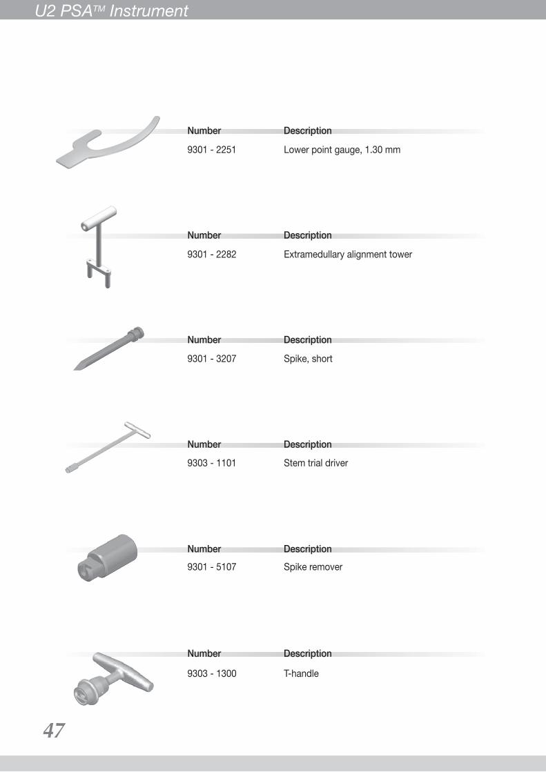
9301 - 2251 Lower point gauge, 1.30 mm
Number Description
9301 - 2282 Extramedullary alignment tower
Number Description
9303 - 1101 Stem trial driver
9303 - 1300 T-handle
Number Description9301 - 5107 Spike remover
Number Description
9301 - 3207 Spike, short
47
U2 PSATM Instrument
48
Number Description
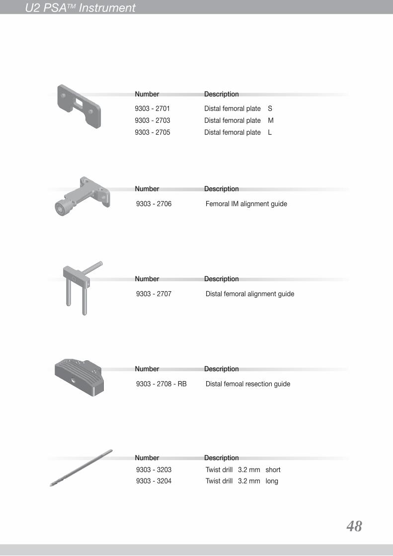
9303 - 2701 Distal femoral plate S 9303 - 2703 Distal femoral plate M 9303 - 2705 Distal femoral plate L
Number Description9303 - 3203 Twist drill 3.2 mm short 9303 - 3204 Twist drill 3.2 mm long
Number Description
9303 - 2707 Distal femoral alignment guide
Number Description
9303 - 2706 Femoral IM alignment guide
U2 PSATM Instrument
Number Description
9303 - 2708 - RB Distal femoal resection guide
49
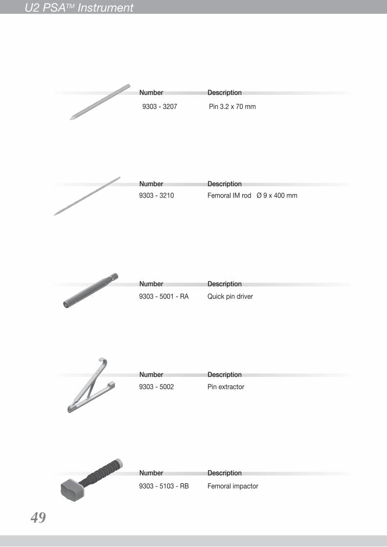
Number Description9303 - 3210 Femoral IM rod Ø 9 x 400 mm
Number Description9303 - 5001 - RA Quick pin driver
Number Description9303 - 5002 Pin extractor
Number Description
9303 - 5103 - RB Femoral impactor
Number Description
9303 - 3207 Pin 3.2 x 70 mm
U2 PSATM Instrument

Number Description9303 - 5119 - RB Universal impactor
Number Description9303 - 5202 Femoral distal spacer 2 mm9303 - 5204 Femoral distal spacer 4 mm9303 - 5206 Femoral distal spacer 6 mm9303 - 5208 Femoral distal spacer 8 mm
Number Description9303 - 5311 Sliding hammer
9303 - 5315 Femoral rotation guide Number Description
9303 - 5329 Screw driver adaptor LNumber Description
Number Description
9303 - 5110 Femoral driver
50
U2 PSATM Instrument

Number Description
Number Description
9303 - 7311 - RA Femoral sizing template #1 9303 - 7312 - RA Femoral sizing template #2 9303 - 7313 - RA Femoral sizing template #3 9303 - 7314 - RA Femoral sizing template #4 9303 - 7315 - RA Femoral sizing template #5 9303 - 7316 - RA Femoral sizing template #6
9303 - 8071 - RA U2 Knee PSA case #1 9303 - 8072 U2 Knee PSA case #2 9303 - 8073 U2 Knee PSA case #3 9303 - 8074 U2 Knee PSA case #4 9303 - 8075 U2 Knee PSA case #5
Number Description
9403 - 1101 - RC Tibial punch handle CM
Number Description9403 - 1203 Tibial sizing template handle
Number Description
9303 - 5333 - RA Femoral valgus adaptor left 9303 - 5334 - RA Femoral valgus adaptor right
51
U2 PSATM Instrument
Number Description
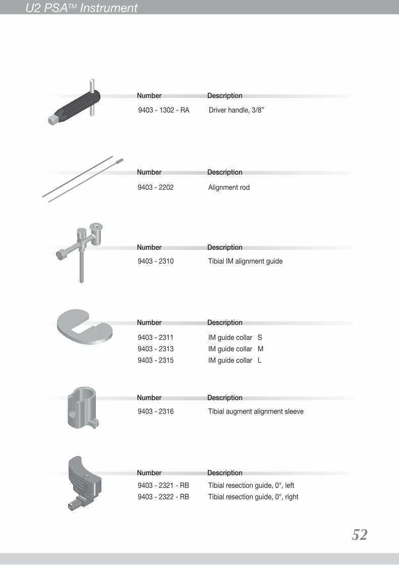
9403 - 2202 Alignment rod
Number Description
9403 - 2310 Tibial IM alignment guide
Number Description
9403 - 2311 IM guide collar S 9403 - 2313 IM guide collar M 9403 - 2315 IM guide collar L
Number Description
Number Description
9403 - 2316 Tibial augment alignment sleeve
9403 - 2321 - RB Tibial resection guide, 0°, left 9403 - 2322 - RB Tibial resection guide, 0°, right
Number Description
9403 - 1302 - RA Driver handle, 3/8”
52
U2 PSATM Instrument

Number Description
9403 - 3009 - RB Straight stem reamer Ø 9 mm9403 - 3010 - RB Straight stem reamer Ø 10 mm9403 - 3011 - RB Straight stem reamer Ø 11 mm9403 - 3012 - RB Straight stem reamer Ø 12 mm9403 - 3013 - RB Straight stem reamer Ø 13 mm9403 - 3014 - RB Straight stem reamer Ø 14 mm9403 - 3015 - RB Straight stem reamer Ø 15 mm9403 - 3016 - RB Straight stem reamer Ø 16 mm9403 - 3017 - RB Straight stem reamer Ø 17 mm9403 - 3018 - RB Straight stem reamer Ø 18 mm9403 - 3019 - RB Straight stem reamer Ø 19 mm9403 - 3020 - RB Straight stem reamer Ø 20 mm9403 - 3021 - RB Straight stem reamer Ø 21 mm9403 - 3022 - RB Straight stem reamer Ø 22 mm9403 - 3023 - RB Straight stem reamer Ø 23 mm9403 - 3024 - RB Straight stem reamer Ø 24 mm
Number Description
9403 - 3201 Tibial IM rod Ø 9 x 430 mm
Number Description
9403 - 3300 Boss reamer
Number Description
9403 - 3302 Offset reamer 2 mm 9403 - 3304 Offset reamer 4 mm
Number Description
9403 - 2414 Tibial stem drill guide, Ø 14 mm
53
U2 PSATM Instrument

Number Description
Number Description
Number Description
Number Description
Number Description
9403 - 3314 Tibial stem drill Ø 14 mm
9403 - 5101 - RC Tibial baseplate driver
9403 - 5102 - RF Tibial baseplate impactor
9403 - 5104 Tibial insert extractor
9403 - 5315 Tibial neutral bushing
Number Description
9403 - 5316 Tibial offset bushing 2 mm 9403 - 5317 Tibial offset bushing 4 mm
54
U2 PSATM Instrument

Number Description
9403 - 5320 Tibial offset fixture
Number Description
9403 - 5322 Tibial offset wrench
Number Description
9403 - 5331 - RA Screw driver adaptor
Number Description
9403 - 5333 Offset bushing wrench
Number Description
9403 - 5334 Stem trial remover
55
U2 PSATM Instrument

Number Description
Number Description
9403 - 5352 Stem extractor adaptor
Number Description
9403 - 5353 Tibial Insert screw holder
Number Description
9403 - 5340 Stem impactor
9403 - 5361 Reamer guide rod Ø 9 mm9403 - 5362 Reamer guide rod Ø 10 mm9403 - 5363 Reamer guide rod Ø 11 mm9403 - 5364 Reamer guide rod Ø 12 mm9403 - 5365 Reamer guide rod Ø 13 mm9403 - 5366 Reamer guide rod Ø 14 mm9403 - 5367 Reamer guide rod Ø 15 mm9403 - 5368 Reamer guide rod Ø 16 mm9403 - 5369 Reamer guide rod Ø 17 mm9403 - 5370 Reamer guide rod Ø 18 mm9403 - 5371 Reamer guide rod Ø 19 mm
56
U2 PSATM Instrument
Special Order Items
Number Description
Number Description
Number Description
Number Description
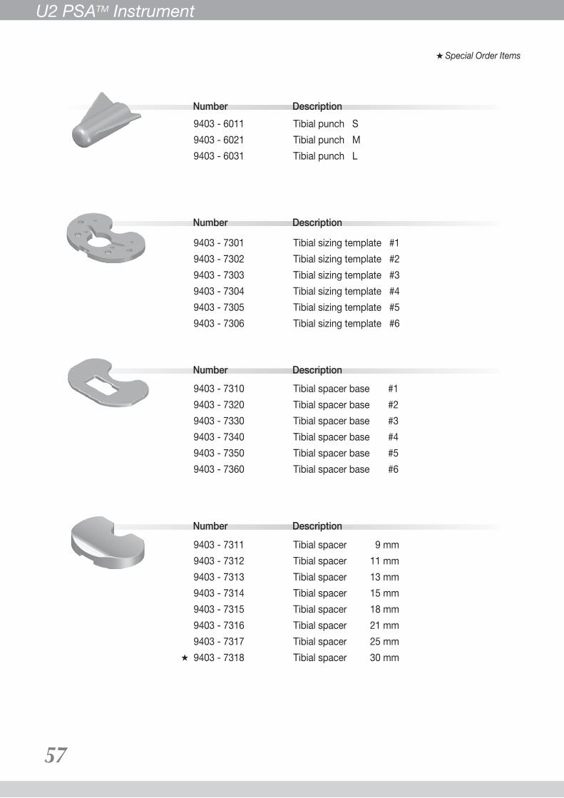
9403 - 6011 Tibial punch S 9403 - 6021 Tibial punch M 9403 - 6031 Tibial punch L
9403 - 7301 Tibial sizing template #1 9403 - 7302 Tibial sizing template #2 9403 - 7303 Tibial sizing template #3 9403 - 7304 Tibial sizing template #4 9403 - 7305 Tibial sizing template #5 9403 - 7306 Tibial sizing template #6
9403 - 7310 Tibial spacer base #19403 - 7320 Tibial spacer base #29403 - 7330 Tibial spacer base #39403 - 7340 Tibial spacer base #49403 - 7350 Tibial spacer base #59403 - 7360 Tibial spacer base #6
9403 - 7311 Tibial spacer 9 mm9403 - 7312 Tibial spacer 11 mm9403 - 7313 Tibial spacer 13 mm9403 - 7314 Tibial spacer 15 mm9403 - 7315 Tibial spacer 18 mm9403 - 7316 Tibial spacer 21 mm9403 - 7317 Tibial spacer 25 mm9403 - 7318 Tibial spacer 30 mm
57
U2 PSATM Instrument
Special Order Items

Safety Statement - U2TM Total Knee System – PSATM Type
58
DESCRIPTION“UNITED” U2 Total Knee System – Posterior Stabilized Augmentable (PSA) type is an extended design of “UNITED” U2 Total Knee system. It is a Patellofemorotibia, polymer / metal / polymer, semi-constrained, cemented knee prosthesis, which has a cobalt-chromium-molybenum (Co-Cr-Mo) alloy femoral component and a tibial component composed of a polyethylene insert machined from compressed molded UHMWPE and a Ti-6Al-4V metallic tibial baseplate. This system is intended for use in patients who require augmentation and/or stem extensions due to inadequate bone stock. There are a variety of components including femoral augment set, tibial augment, stem extension and offset stem adapter that provide more choices for surgeon to treat their patients. In addition, this system provides more stability for patients with inadequate mediolateral, anterioposterior or varus-valgus soft tissue imbalance. For total knee replacement, “UNITED” patella components are intended to be used with U2 Total Knee System – PSA Type. The components of U2 Total Knee system-PSA Type are listed as below.
MATERIALSASTM F75 Co-Cr-Mo alloy Femoral componentASTM F1537/ASTM F75 Co-Cr-Mo alloy Femoral augment set ASTM F136/ISO 5832-3 Ti-6Al-4V ELI alloy Tibial baseplate, Femoral augment set, Tibial augment, Offset stem adapter, Femoral screw, StemASTM F648/ISO 5834 UHMWPE Tibial insertASTM F1580 Titanium Metallic powder for Ti plasma spray
INDICATIONSThis device is indicated in knee arthroplasty in skeletally mature patients with severe knee pain and disability due to rheumatoid arthritis, osteoarthritis, primary and secondary traumatic arthritis, polyarthritis, collagen disorders, avascular necrosis of the femoral condyle or pseudogout, posttraumatic loss of joint configuration, particularly when there is patellofemoral erosion, dysfunction or prior patellectomy, moderate valgus, varus, or flexion contraction. This device is intended for use in patients who require augmentation and/or stem extensions due to inadequate bone stock and/or require increased stabilization for tibiofemoral joint due to soft tissue imbalance. The femoral and tibial augments are to be attached to their respective components with a fixation screw or screws. Note: In the US, this device is for cemented use only.
CONTRAINDICATIONSThe U2 Total Knee System is contraindicated in patients who with:−any active or suspected latent of infection in the affected joint. −skeletal immaturity.−either mental or neuromuscular disorders which would create an unacceptable risk of prosthesis instability or complications in postoperative care.−rheumatoid arthritis and an ulcer of the skin or a history of recurrent−breakdown of the skin.
ADVERSE EFFECTS Potential adverse effects include infection, loosening of the components, breakage or bending of the components, or change in position of the components. Dislocation can occur due to inappropriate patient activity, trauma or other biomechanical considerations. Loosening may result from inadequate initial fixation, latent infection, premature loading of the prosthesis, component malalignment, osteolysis or trauma. Breakage or bending may result due to inadequate support of the component by the underlying bone or poor component fixation. Wear of polyethylene components has occurred and literature reports have associated its occurrence with bone resorption, loosening and infection. Other potential adverse effects of total knee surgery include genitourinary disorders; gastrointestinal disorders; neurovascular damage, thromboembolic disease, myocardial infarction and other less common adverse effects. Adverse effects may necessitate reoperation, revision, arthrodesis of the involved joint, and/or amputation of the limb. Due to the many biological, mechanical and physicochemical factors which affect these devices, the components cannot be expected to indefinitely withstand the activity level and loads of normal healthy bone.
WARNINGS AND PRECAUTIONS Familiarity with and attention to appropriate surgical technique for total knee arthroplasty and the U2 Total Knee System – PSA Type is essential for success of the total knee procedure. Only surgeons who have reviewed the literature regarding total knee surgery and have been training in the technique should utilize the device. Patients should be instructed the limitations of the prosthesis, including, but not limited to, the impact of excessive loading through patient weight or activity, and be taught to govern their activities accordingly. If the patient is involved in an occupation or activity which includes substantial walking, running, lifting, or muscle strain, the resultant forces can cause failure of the fixation, the device, or both. The prosthesis will not restore function to the level expected with normal healthy bone, and the patient should not have unrealistic functional expectations.AAccordingly, strict adherence to the indications, contraindications, precaution and warnings for this product is essential to potentially maximize service life. Appropriate selection, placement and fixation of the total knee components are critical factors that affect implant service life. As in the case of all prosthetic implants, the durability of these components is affected by numerous biologic biomechanic and other extrinsic factors, which limit their service life. The surgeon must not allow damage to polished bearing surfaces because this may accelerate wear of the components. Discard all damaged or mishandled implants. Keep bearing areas clean and free of debris prior to assembly. The tibial augment is only to be used with bone cement. Components of the U2 Total Knee System – PSA Type should not be used with those of another manufacturer's total knee component since articular and dimensional compatibility cannot be assured. Femoral component and tibial insert should belong to the one single system; therefore, femoral component of U2 Total Knee System – PSA Type cannot be coupled with tibial insert of U2 Total Knee System, vice versa. Intentional removal of the plastic tibial insert after its assembly into the tibial tray results in the destruction of the plastic insert. Care should be taken not to nick or notch the surface of the tibial tray during insert removal. Return all packages with flaws in the sterile barrier to the supplier. This device is for single use only. Do not reuse and Do not resterilize. Reuse of this product will cause the risk of cross infection and unpredictable health threat.
UTILIZATION AND IMPLANTATIONSelection of the U2 Total Knee System – PSA Type depends on the requirement of the patient. The surgeon should become thoroughly familiar with the technique of implantation of the prostheses by: (1) appropriate reading of the literature and (2) training in the operative skills and techniques required for total knee arthroplasty surgery. The trial components should be used for size determination, trial reduction and range of motion evaluation. Radiographic templates are available to assist in the preoperative prediction component size and style.
PACKAGING, LABELING AND STERILIZATIONThis device has been sterilized by gamma radiation. The packaging of all sterile products should be inspected for their integrity and should be accepted only with proper packaging and labeling intact. Care should be taken to prevent contamination of the component. In the event of contamination, this product must be discarded. If the package is opened, but the product is not used, the component must not be resterilized and must be discarded or returned to the supplier.
IMPORTANT FOR OPENED COMPONENTSThe plastic components, if opened, are not permitted be re-sterilization by any method. The metal components, if opened, please return to United Orthopedic Corporation. A suitable handing in cleaning (if necessary), packaging and gamma radiation will be done.
SAFETY INFORMATION IN THE MAGNETIC RESONANCE (MR) ENVIONMENTThe U2 Total Knee System–PSA type has not been evaluated for safety and compatibility in the MR environment. The U2 Total Knee System–PSA type has not been tested for heating or migration in the MR environment.

12F., No. 80, Sec. 1, Chenggong Rd., Yonghe Dist., New Taipei City 23452, TaiwanTel: +886 2 2929-4567 Fax: +886 2 2922-4567
www.uoc.com.tw

For our valued distribution partners, you can reach our customer service associates at [email protected] For assistance on general and/or product related inquiries, please email us at [email protected]
0299-S-05-04-US
All Rights Reserved, 2014 United Orthopedic Corp.www.uocusa.com
Please refer to the product-specific package inserts for important information, including indications, contraindications, warnings, precautions, and potential adverse effects.
20 Fairbanks, Suite 173Irvine, CA 92618Tel: (949) 328-3366Fax: (949) 328-3367