type test certificate, reb670 ansi 1.2 (english - abb ltd · disclaimer the data, examples and...
TRANSCRIPT
Relion® 670 series
Busbar protection REB670 ANSIType test certificate

Document ID: 1MRK505212-TUSIssued: February 2015
Revision: DProduct version: 1.2
© Copyright 2012 ABB. All rights reserved
CopyrightThis document and parts thereof must not be reproduced or copied without writtenpermission from ABB, and the contents thereof must not be imparted to a third party,nor used for any unauthorized purpose.
The software and hardware described in this document is furnished under a license andmay be used or disclosed only in accordance with the terms of such license.
TrademarksABB and Relion are registered trademarks of the ABB Group. All other brand orproduct names mentioned in this document may be trademarks or registeredtrademarks of their respective holders.
WarrantyPlease inquire about the terms of warranty from your nearest ABB representative.
ABB Inc.
1021 Main Campus Drive
Raleigh, NC 27606, USA
Toll Free: 1-800-HELP-365, menu option #8
ABB Inc.
3450 Harvester Road
Burlington, ON L7N 3W5, Canada
Toll Free: 1-800-HELP-365, menu option #8
ABB Mexico S.A. de C.V.
Paseo de las Americas No. 31 Lomas Verdes 3a secc.
53125, Naucalpan, Estado De Mexico, MEXICO
Phone: (+1) 440-585-7804, menu option #8
DisclaimerThe data, examples and diagrams in this manual are included solely for the concept orproduct description and are not to be deemed as a statement of guaranteed properties.All persons responsible for applying the equipment addressed in this manual mustsatisfy themselves that each intended application is suitable and acceptable, includingthat any applicable safety or other operational requirements are complied with. Inparticular, any risks in applications where a system failure and/or product failure wouldcreate a risk for harm to property or persons (including but not limited to personalinjuries or death) shall be the sole responsibility of the person or entity applying theequipment, and those so responsible are hereby requested to ensure that all measuresare taken to exclude or mitigate such risks.
This document has been carefully checked by ABB but deviations cannot becompletely ruled out. In case any errors are detected, the reader is kindly requested tonotify the manufacturer. Other than under explicit contractual commitments, in noevent shall ABB be responsible or liable for any loss or damage resulting from the useof this manual or the application of the equipment.
ConformityThis product complies with the directive of the Council of the European Communitieson the approximation of the laws of the Member States relating to electromagneticcompatibility (EMC Directive 2004/108/EC) and concerning electrical equipment foruse within specified voltage limits (Low-voltage directive 2006/95/EC). Thisconformity is the result of tests conducted by ABB in accordance with the productstandards EN 50263 and EN 60255-26 for the EMC directive, and with the productstandards EN 60255-1 and EN 60255-27 for the low voltage directive. The product isdesigned in accordance with the international standards of the IEC 60255 series andANSI C37.90.
Table of contents
Section 1 General..................................................................................3Definitions.................................................................................................4
Section 2 Energizing quantities, rated values and limits.......................5Analog inputs............................................................................................5Auxiliary DC voltage.................................................................................6Binary inputs and outputs.........................................................................6Influencing factors...................................................................................12
Section 3 Type tests according to standards......................................13
Section 4 Differential protection..........................................................15
Section 5 Current protection................................................................17
Section 6 Voltage protection...............................................................21
Section 7 Frequency protection...........................................................23
Section 8 Multipurpose protection.......................................................25
Section 9 Secondary system supervision............................................27
Section 10 Control.................................................................................29
Section 11 Logic....................................................................................31
Section 12 Monitoring............................................................................33
Section 13 Metering..............................................................................37
Section 14 Station communication........................................................39
Section 15 Remote communication.......................................................41
Section 16 Hardware.............................................................................43IED..........................................................................................................43Connection system.................................................................................43
Section 17 Basic IED functions.............................................................45
Table of contents
1Type test certificate

Section 18 Inverse characteristics.........................................................47
Table of contents
2Type test certificate
Section 1 General
1.1 Type test data
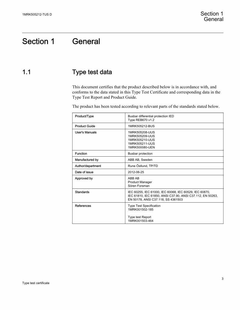
This document certifies that the product described below is in accordance with, andconforms to the data stated in this Type Test Certificate and corresponding data in theType Test Report and Product Guide.
The product has been tested according to relevant parts of the standards stated below.
Product/Type Busbar differential protection IEDType REB670 v1.2
Product Guide 1MRK505212-BUS
User's Manuals 1MRK505208-UUS1MRK505209-UUS1MRK505210-UUS1MRK505211-UUS1MRK500080-UEN
Function Busbar protection
Manufactured by ABB AB, Sweden
Author/department Rune Östlund, TP/TD
Date of issue 2012-06-25
Approved by ABB ABProduct ManagerSören Forsman
Standards IEC 60255, IEC 61000, IEC 60068, IEC 60529, IEC 60870,IEC 61810, IEC 61850, ANSI C37.90, ANSI C37.112, EN 50263,EN 50178, ANSI C37.118, SS 4361503
References Type Test Specification1MRK001502-185 Type test Report1MRK001503-464
1MRK505212-TUS D Section 1General
3Type test certificate
1.2 Definitions
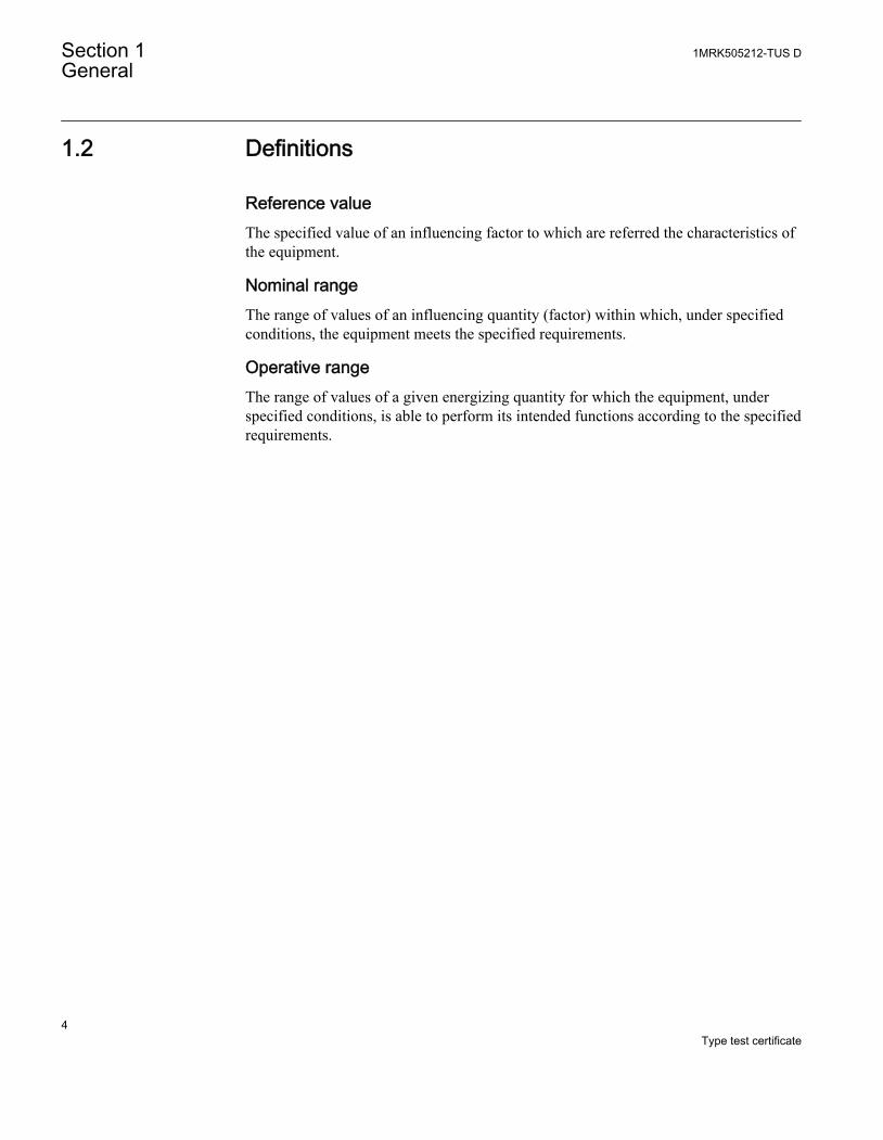
Reference valueThe specified value of an influencing factor to which are referred the characteristics ofthe equipment.
Nominal rangeThe range of values of an influencing quantity (factor) within which, under specifiedconditions, the equipment meets the specified requirements.
Operative rangeThe range of values of a given energizing quantity for which the equipment, underspecified conditions, is able to perform its intended functions according to the specifiedrequirements.
Section 1 1MRK505212-TUS DGeneral
4Type test certificate
Section 2 Energizing quantities, rated values andlimits
2.1 Analog inputs
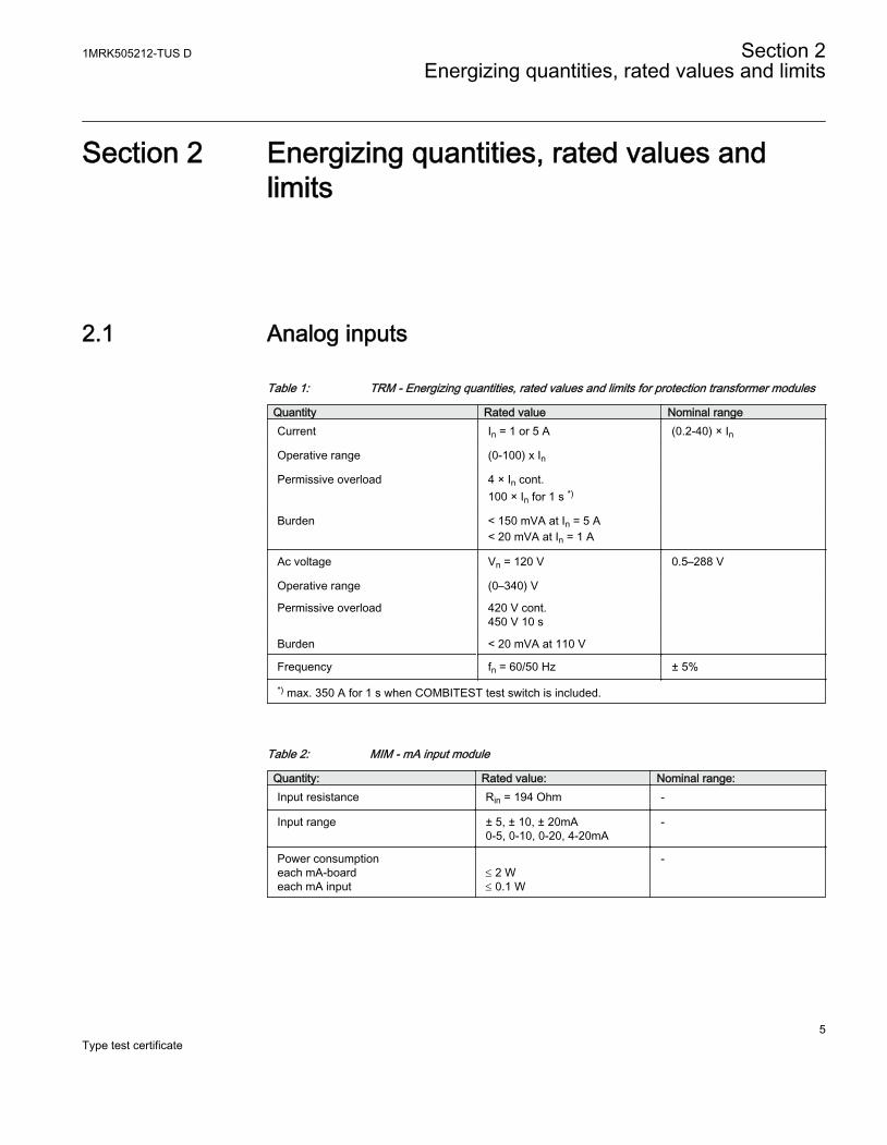
Table 1: TRM - Energizing quantities, rated values and limits for protection transformer modules
Quantity Rated value Nominal rangeCurrent In = 1 or 5 A (0.2-40) × In
Operative range (0-100) x In
Permissive overload 4 × In cont.100 × In for 1 s *)
Burden < 150 mVA at In = 5 A< 20 mVA at In = 1 A
Ac voltage Vn = 120 V 0.5–288 V
Operative range (0–340) V
Permissive overload 420 V cont.450 V 10 s
Burden < 20 mVA at 110 V
Frequency fn = 60/50 Hz ± 5%
*) max. 350 A for 1 s when COMBITEST test switch is included.
Table 2: MIM - mA input module
Quantity: Rated value: Nominal range:Input resistance Rin = 194 Ohm -
Input range ± 5, ± 10, ± 20mA0-5, 0-10, 0-20, 4-20mA
-
Power consumptioneach mA-boardeach mA input
£ 2 W£ 0.1 W
-
1MRK505212-TUS D Section 2Energizing quantities, rated values and limits
5Type test certificate
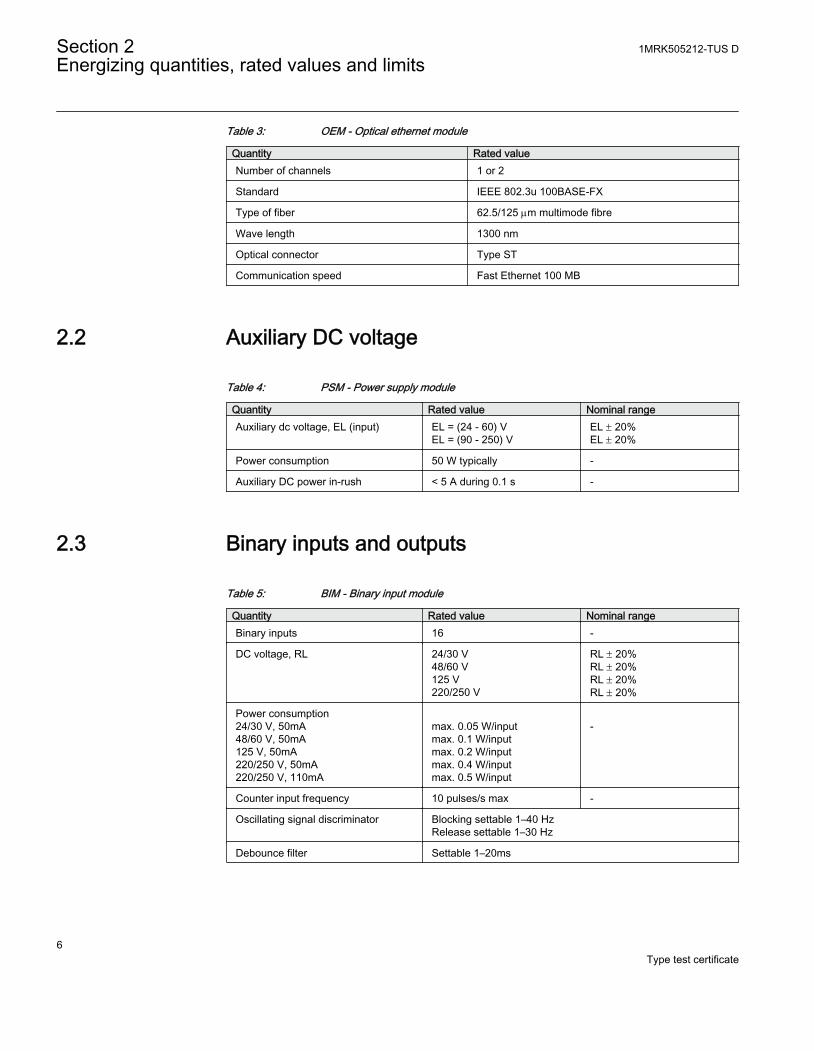
Table 3: OEM - Optical ethernet module
Quantity Rated valueNumber of channels 1 or 2
Standard IEEE 802.3u 100BASE-FX
Type of fiber 62.5/125 mm multimode fibre
Wave length 1300 nm
Optical connector Type ST
Communication speed Fast Ethernet 100 MB
2.2 Auxiliary DC voltage
Table 4: PSM - Power supply module
Quantity Rated value Nominal rangeAuxiliary dc voltage, EL (input) EL = (24 - 60) V
EL = (90 - 250) VEL ± 20%EL ± 20%
Power consumption 50 W typically -
Auxiliary DC power in-rush < 5 A during 0.1 s -
2.3 Binary inputs and outputs
Table 5: BIM - Binary input module
Quantity Rated value Nominal rangeBinary inputs 16 -
DC voltage, RL 24/30 V48/60 V125 V220/250 V
RL ± 20%RL ± 20%RL ± 20%RL ± 20%
Power consumption24/30 V, 50mA48/60 V, 50mA125 V, 50mA220/250 V, 50mA220/250 V, 110mA
max. 0.05 W/inputmax. 0.1 W/inputmax. 0.2 W/inputmax. 0.4 W/inputmax. 0.5 W/input
-
Counter input frequency 10 pulses/s max -
Oscillating signal discriminator Blocking settable 1–40 HzRelease settable 1–30 Hz
Debounce filter Settable 1–20ms
Section 2 1MRK505212-TUS DEnergizing quantities, rated values and limits
6Type test certificate
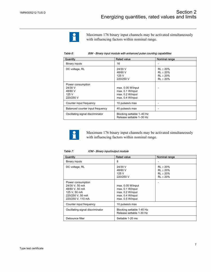
Maximum 176 binary input channels may be activated simultaneouslywith influencing factors within nominal range.
Table 6: BIM - Binary input module with enhanced pulse counting capabilities
Quantity Rated value Nominal rangeBinary inputs 16 -
DC voltage, RL 24/30 V48/60 V125 V220/250 V
RL ± 20%RL ± 20%RL ± 20%RL ± 20%
Power consumption24/30 V48/60 V125 V220/250 V
max. 0.05 W/inputmax. 0.1 W/inputmax. 0.2 W/inputmax. 0.4 W/input
-
Counter input frequency 10 pulses/s max -
Balanced counter input frequency 40 pulses/s max -
Oscillating signal discriminator Blocking settable 1–40 HzRelease settable 1–30 Hz
Maximum 176 binary input channels may be activated simultaneouslywith influencing factors within nominal range.
Table 7: IOM - Binary input/output module
Quantity Rated value Nominal rangeBinary inputs 8 -
DC voltage, RL 24/30 V48/60 V125 V220/250 V
RL ± 20%RL ± 20%RL ± 20%RL ± 20%
Power consumption24/30 V, 50 mA48/60 V, 50 mA125 V, 50 mA220/250 V, 50 mA220/250 V, 110 mA
max. 0.05 W/inputmax. 0.1 W/inputmax. 0.2 W/inputmax. 0.4 W/inputmax. 0.5 W/input
-
Counter input frequency 10 pulses/s max
Oscillating signal discriminator Blocking settable 1-40 HzRelease settable 1-30 Hz
Debounce filter Settable 1-20 ms
1MRK505212-TUS D Section 2Energizing quantities, rated values and limits
7Type test certificate
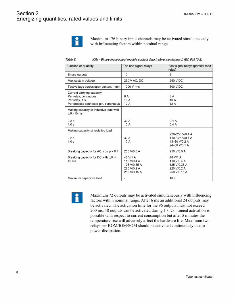
Maximum 176 binary input channels may be activated simultaneouslywith influencing factors within nominal range.
Table 8: IOM - Binary input/output module contact data (reference standard: IEC 61810-2)
Function or quantity Trip and signal relays Fast signal relays (parallel reedrelay)
Binary outputs 10 2
Max system voltage 250 V AC, DC 250 V DC
Test voltage across open contact, 1 min 1000 V rms 800 V DC
Current carrying capacityPer relay, continuousPer relay, 1 sPer process connector pin, continuous
8 A10 A12 A
8 A10 A12 A
Making capacity at inductive load withL/R>10 ms 0.2 s1.0 s
30 A10 A
0.4 A0.4 A
Making capacity at resistive load 0.2 s1.0 s
30 A10 A
220–250 V/0.4 A110–125 V/0.4 A48–60 V/0.2 A24–30 V/0.1 A
Breaking capacity for AC, cos φ > 0.4 250 V/8.0 A 250 V/8.0 A
Breaking capacity for DC with L/R <40 ms
48 V/1 A110 V/0.4 A125 V/0.35 A220 V/0.2 A250 V/0.15 A
48 V/1 A110 V/0.4 A125 V/0.35 A220 V/0.2 A250 V/0.15 A
Maximum capacitive load - 10 nF
Maximum 72 outputs may be activated simultaneously with influencingfactors within nominal range. After 6 ms an additional 24 outputs maybe activated. The activation time for the 96 outputs must not exceed200 ms. 48 outputs can be activated during 1 s. Continued activation ispossible with respect to current consumption but after 5 minutes thetemperature rise will adversely affect the hardware life. Maximum tworelays per BOM/IOM/SOM should be activated continuously due topower dissipation.
Section 2 1MRK505212-TUS DEnergizing quantities, rated values and limits
8Type test certificate
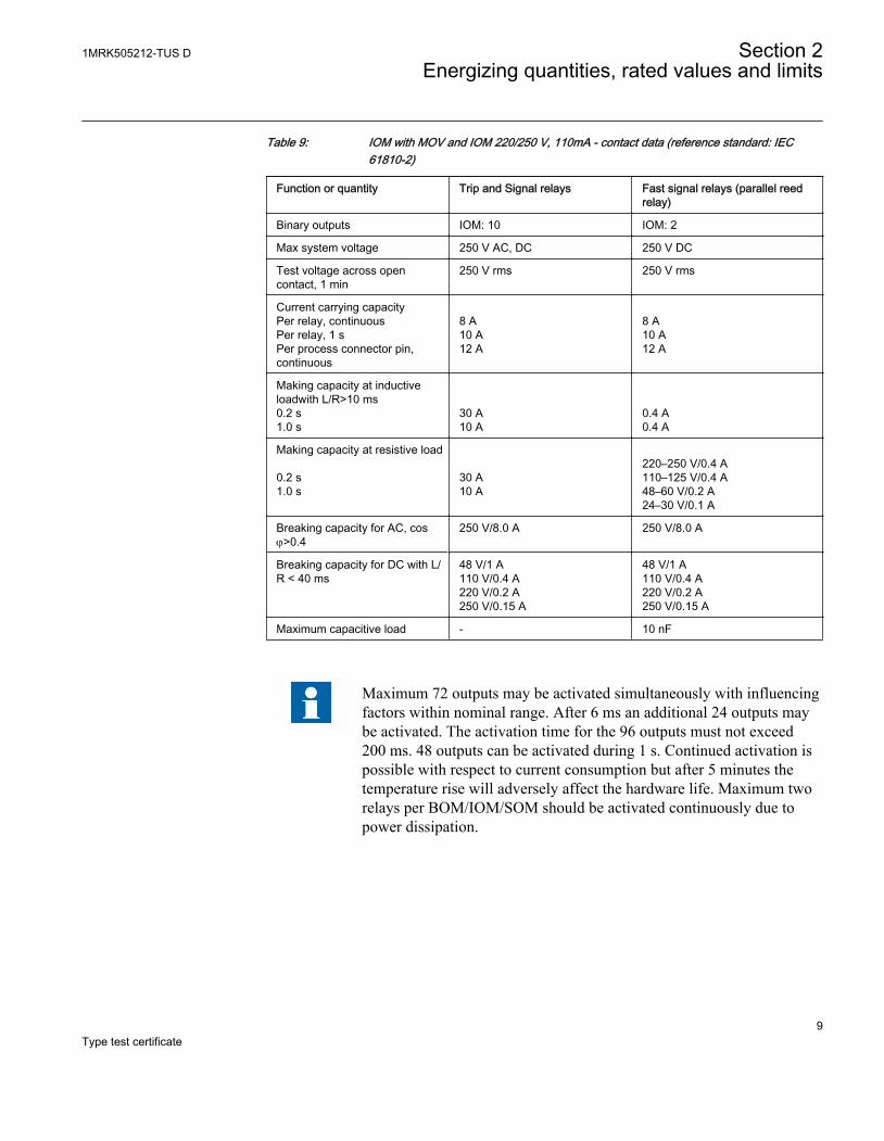
Table 9: IOM with MOV and IOM 220/250 V, 110mA - contact data (reference standard: IEC61810-2)
Function or quantity Trip and Signal relays Fast signal relays (parallel reedrelay)
Binary outputs IOM: 10 IOM: 2
Max system voltage 250 V AC, DC 250 V DC
Test voltage across opencontact, 1 min
250 V rms 250 V rms
Current carrying capacityPer relay, continuousPer relay, 1 sPer process connector pin,continuous
8 A10 A12 A
8 A10 A12 A
Making capacity at inductiveloadwith L/R>10 ms0.2 s1.0 s
30 A10 A
0.4 A0.4 A
Making capacity at resistive load 0.2 s1.0 s
30 A10 A
220–250 V/0.4 A110–125 V/0.4 A48–60 V/0.2 A24–30 V/0.1 A
Breaking capacity for AC, cosj>0.4
250 V/8.0 A 250 V/8.0 A
Breaking capacity for DC with L/R < 40 ms
48 V/1 A110 V/0.4 A220 V/0.2 A250 V/0.15 A
48 V/1 A110 V/0.4 A220 V/0.2 A250 V/0.15 A
Maximum capacitive load - 10 nF
Maximum 72 outputs may be activated simultaneously with influencingfactors within nominal range. After 6 ms an additional 24 outputs maybe activated. The activation time for the 96 outputs must not exceed200 ms. 48 outputs can be activated during 1 s. Continued activation ispossible with respect to current consumption but after 5 minutes thetemperature rise will adversely affect the hardware life. Maximum tworelays per BOM/IOM/SOM should be activated continuously due topower dissipation.
1MRK505212-TUS D Section 2Energizing quantities, rated values and limits
9Type test certificate
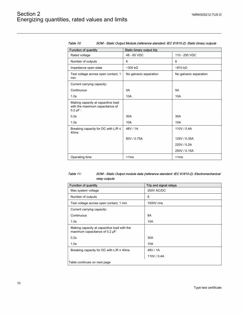
Table 10: SOM - Static Output Module (reference standard: IEC 61810-2): Static binary outputs
Function of quantity Static binary output tripRated voltage 48 - 60 VDC 110 - 250 VDC
Number of outputs 6 6
Impedance open state ~300 kΩ ~810 kΩ
Test voltage across open contact, 1min
No galvanic separation No galvanic separation
Current carrying capacity:
Continuous 5A 5A
1.0s 10A 10A
Making capacity at capacitive loadwith the maximum capacitance of0.2 μF :
0.2s 30A 30A
1.0s 10A 10A
Breaking capacity for DC with L/R ≤40ms
48V / 1A 110V / 0.4A
60V / 0.75A 125V / 0.35A
220V / 0.2A
250V / 0.15A
Operating time <1ms <1ms
Table 11: SOM - Static Output module data (reference standard: IEC 61810-2): Electromechanicalrelay outputs
Function of quantity Trip and signal relaysMax system voltage 250V AC/DC
Number of outputs 6
Test voltage across open contact, 1 min 1000V rms
Current carrying capacity:
Continuous 8A
1.0s 10A
Making capacity at capacitive load with themaximum capacitance of 0.2 μF:
0.2s 30A
1.0s 10A
Breaking capacity for DC with L/R ≤ 40ms 48V / 1A
110V / 0.4A
Table continues on next page
Section 2 1MRK505212-TUS DEnergizing quantities, rated values and limits
10Type test certificate
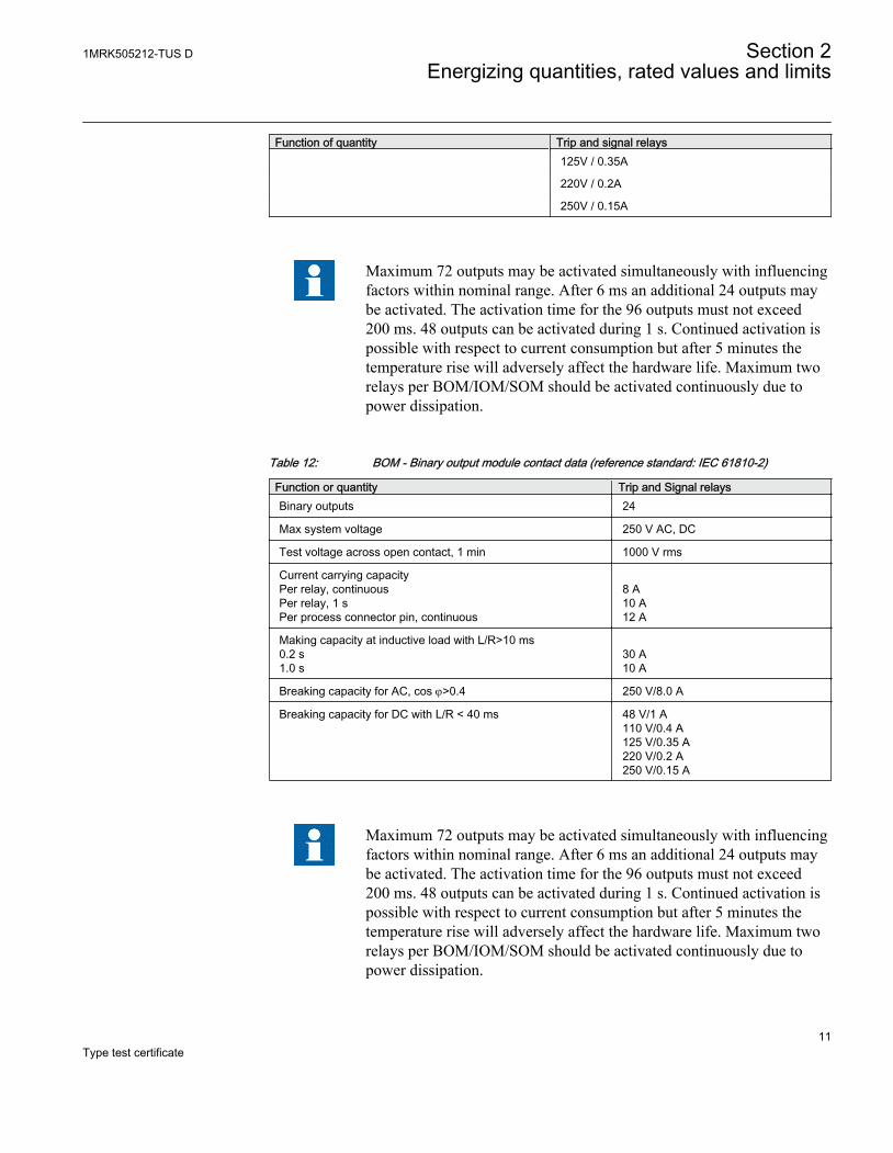
Function of quantity Trip and signal relays 125V / 0.35A
220V / 0.2A
250V / 0.15A
Maximum 72 outputs may be activated simultaneously with influencingfactors within nominal range. After 6 ms an additional 24 outputs maybe activated. The activation time for the 96 outputs must not exceed200 ms. 48 outputs can be activated during 1 s. Continued activation ispossible with respect to current consumption but after 5 minutes thetemperature rise will adversely affect the hardware life. Maximum tworelays per BOM/IOM/SOM should be activated continuously due topower dissipation.
Table 12: BOM - Binary output module contact data (reference standard: IEC 61810-2)
Function or quantity Trip and Signal relaysBinary outputs 24
Max system voltage 250 V AC, DC
Test voltage across open contact, 1 min 1000 V rms
Current carrying capacityPer relay, continuousPer relay, 1 sPer process connector pin, continuous
8 A10 A12 A
Making capacity at inductive load with L/R>10 ms0.2 s1.0 s
30 A10 A
Breaking capacity for AC, cos j>0.4 250 V/8.0 A
Breaking capacity for DC with L/R < 40 ms 48 V/1 A110 V/0.4 A125 V/0.35 A220 V/0.2 A250 V/0.15 A
Maximum 72 outputs may be activated simultaneously with influencingfactors within nominal range. After 6 ms an additional 24 outputs maybe activated. The activation time for the 96 outputs must not exceed200 ms. 48 outputs can be activated during 1 s. Continued activation ispossible with respect to current consumption but after 5 minutes thetemperature rise will adversely affect the hardware life. Maximum tworelays per BOM/IOM/SOM should be activated continuously due topower dissipation.
1MRK505212-TUS D Section 2Energizing quantities, rated values and limits
11Type test certificate
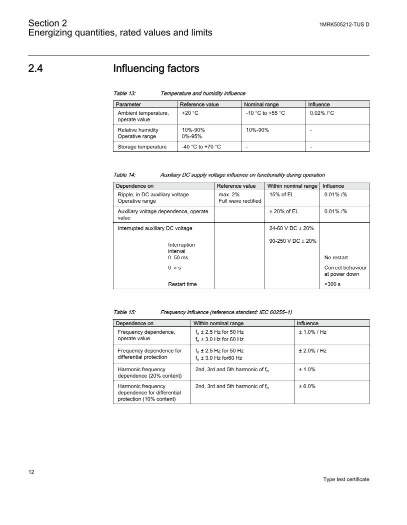
2.4 Influencing factors
Table 13: Temperature and humidity influence
Parameter Reference value Nominal range InfluenceAmbient temperature,operate value
+20 °C -10 °C to +55 °C 0.02% /°C
Relative humidityOperative range
10%-90%0%-95%
10%-90% -
Storage temperature -40 °C to +70 °C - -
Table 14: Auxiliary DC supply voltage influence on functionality during operation
Dependence on Reference value Within nominal range InfluenceRipple, in DC auxiliary voltageOperative range
max. 2%Full wave rectified
15% of EL 0.01% /%
Auxiliary voltage dependence, operatevalue
± 20% of EL 0.01% /%
Interrupted auxiliary DC voltage
24-60 V DC ± 20% 90-250 V DC ± 20%
Interruptioninterval0–50 ms
No restart
0–∞ s Correct behaviourat power down
Restart time <300 s
Table 15: Frequency influence (reference standard: IEC 60255–1)
Dependence on Within nominal range InfluenceFrequency dependence,operate value
fn ± 2.5 Hz for 50 Hzfn ± 3.0 Hz for 60 Hz
± 1.0% / Hz
Frequency dependence fordifferential protection
fn ± 2.5 Hz for 50 Hzfn ± 3.0 Hz for60 Hz
± 2.0% / Hz
Harmonic frequencydependence (20% content)
2nd, 3rd and 5th harmonic of fn ± 1.0%
Harmonic frequencydependence for differentialprotection (10% content)
2nd, 3rd and 5th harmonic of fn ± 6.0%
Section 2 1MRK505212-TUS DEnergizing quantities, rated values and limits
12Type test certificate
Section 3 Type tests according to standards
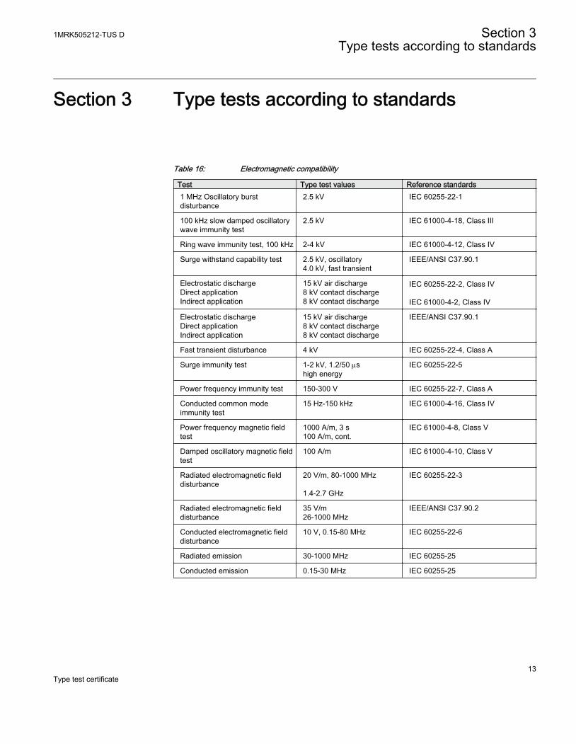
Table 16: Electromagnetic compatibility
Test Type test values Reference standards1 MHz Oscillatory burstdisturbance
2.5 kV IEC 60255-22-1
100 kHz slow damped oscillatorywave immunity test
2.5 kV IEC 61000-4-18, Class III
Ring wave immunity test, 100 kHz 2-4 kV IEC 61000-4-12, Class IV
Surge withstand capability test 2.5 kV, oscillatory4.0 kV, fast transient
IEEE/ANSI C37.90.1
Electrostatic dischargeDirect applicationIndirect application
15 kV air discharge8 kV contact discharge8 kV contact discharge
IEC 60255-22-2, Class IV IEC 61000-4-2, Class IV
Electrostatic dischargeDirect applicationIndirect application
15 kV air discharge8 kV contact discharge8 kV contact discharge
IEEE/ANSI C37.90.1
Fast transient disturbance 4 kV IEC 60255-22-4, Class A
Surge immunity test 1-2 kV, 1.2/50 mshigh energy
IEC 60255-22-5
Power frequency immunity test 150-300 V IEC 60255-22-7, Class A
Conducted common modeimmunity test
15 Hz-150 kHz IEC 61000-4-16, Class IV
Power frequency magnetic fieldtest
1000 A/m, 3 s100 A/m, cont.
IEC 61000-4-8, Class V
Damped oscillatory magnetic fieldtest
100 A/m IEC 61000-4-10, Class V
Radiated electromagnetic fielddisturbance
20 V/m, 80-1000 MHz 1.4-2.7 GHz
IEC 60255-22-3
Radiated electromagnetic fielddisturbance
35 V/m26-1000 MHz
IEEE/ANSI C37.90.2
Conducted electromagnetic fielddisturbance
10 V, 0.15-80 MHz IEC 60255-22-6
Radiated emission 30-1000 MHz IEC 60255-25
Conducted emission 0.15-30 MHz IEC 60255-25
1MRK505212-TUS D Section 3Type tests according to standards
13Type test certificate
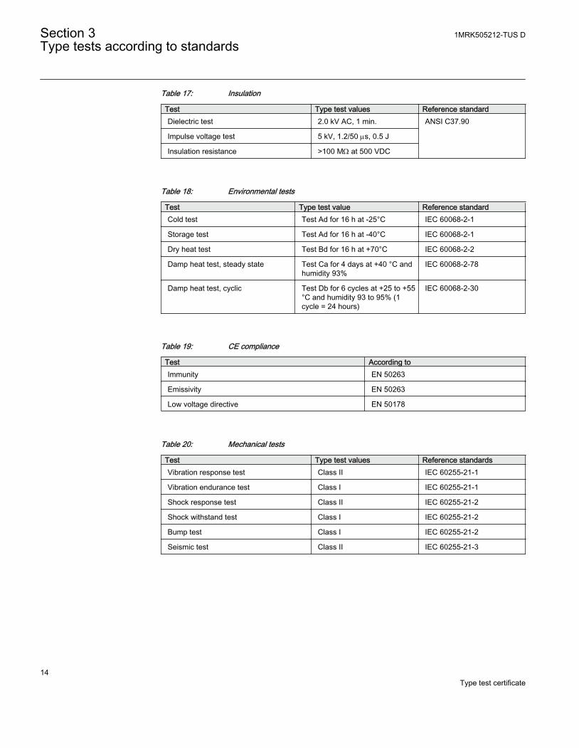
Table 17: Insulation
Test Type test values Reference standardDielectric test 2.0 kV AC, 1 min. ANSI C37.90
Impulse voltage test 5 kV, 1.2/50 ms, 0.5 J
Insulation resistance >100 MW at 500 VDC
Table 18: Environmental tests
Test Type test value Reference standardCold test Test Ad for 16 h at -25°C IEC 60068-2-1
Storage test Test Ad for 16 h at -40°C IEC 60068-2-1
Dry heat test Test Bd for 16 h at +70°C IEC 60068-2-2
Damp heat test, steady state Test Ca for 4 days at +40 °C andhumidity 93%
IEC 60068-2-78
Damp heat test, cyclic Test Db for 6 cycles at +25 to +55°C and humidity 93 to 95% (1cycle = 24 hours)
IEC 60068-2-30
Table 19: CE compliance
Test According toImmunity EN 50263
Emissivity EN 50263
Low voltage directive EN 50178
Table 20: Mechanical tests
Test Type test values Reference standardsVibration response test Class II IEC 60255-21-1
Vibration endurance test Class I IEC 60255-21-1
Shock response test Class II IEC 60255-21-2
Shock withstand test Class I IEC 60255-21-2
Bump test Class I IEC 60255-21-2
Seismic test Class II IEC 60255-21-3
Section 3 1MRK505212-TUS DType tests according to standards
14Type test certificate
Section 4 Differential protection
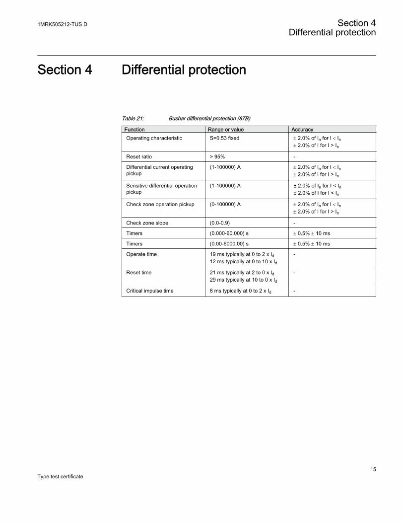
Table 21: Busbar differential protection (87B)
Function Range or value AccuracyOperating characteristic S=0.53 fixed ± 2.0% of In for I < In
± 2.0% of I for I > In
Reset ratio > 95% -
Differential current operatingpickup
(1-100000) A ± 2.0% of In for I < In± 2.0% of I for I > In
Sensitive differential operationpickup
(1-100000) A ± 2.0% of In for I < In± 2.0% of I for I < In
Check zone operation pickup (0-100000) A ± 2.0% of In for I < In± 2.0% of I for I > In
Check zone slope (0.0-0.9) -
Timers (0.000-60.000) s ± 0.5% ± 10 ms
Timers (0.00-6000.00) s ± 0.5% ± 10 ms
Operate time 19 ms typically at 0 to 2 x Id12 ms typically at 0 to 10 x Id
-
Reset time 21 ms typically at 2 to 0 x Id29 ms typically at 10 to 0 x Id
-
Critical impulse time 8 ms typically at 0 to 2 x Id -
1MRK505212-TUS D Section 4Differential protection
15Type test certificate

16
Section 5 Current protection
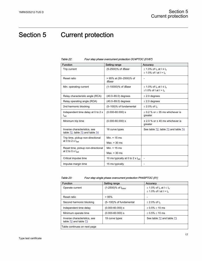
Table 22: Four step phase overcurrent protection OC4PTOC (51/67)
Function Setting range AccuracyTrip current (5-2500)% of lBase ± 1.0% of In at I ≤ In
± 1.0% of I at I > In
Reset ratio > 95% at (50–2500)% oflBase
-
Min. operating current (1-10000)% of lBase ± 1.0% of In at I ≤ In±1.0% of I at I > In
Relay characteristic angle (RCA) (40.0–65.0) degrees ± 2.0 degrees
Relay operating angle (ROA) (40.0–89.0) degrees ± 2.0 degrees
2nd harmonic blocking (5–100)% of fundamental ± 2.0% of In
Independent time delay at 0 to 2 xIset
(0.000-60.000) s ± 0.2 % or ± 35 ms whichever isgreater
Minimum trip time (0.000-60.000) s ± 2.0 % or ± 40 ms whichever isgreater
Inverse characteristics, seetable 72, table 73 and table 74
16 curve types See table 72, table 73 and table 74
Trip time, pickup non-directionalat 0 to 2 x Iset
Min. = 15 ms
Max. = 30 ms
Reset time, pickup non-directionalat 2 to 0 x Iset
Min. = 15 ms
Max. = 30 ms
Critical impulse time 10 ms typically at 0 to 2 x Iset -
Impulse margin time 15 ms typically -
Table 23: Four step single phase overcurrent protection PH4SPTOC (51)
Function Setting range AccuracyOperate current (1-2500)% of lbase ± 1.0% of In at I £ In
± 1.0% of I at I > In
Reset ratio > 95% -
Second harmonic blocking (5–100)% of fundamental ± 2.0% of In
Independent time delay (0.000-60.000) s ± 0.5% ± 10 ms
Minimum operate time (0.000-60.000) s ± 0.5% ± 10 ms
Inverse characteristics, seetable 72 and table 73
19 curve types See table 72 and table 73
Table continues on next page
1MRK505212-TUS D Section 5Current protection
17Type test certificate
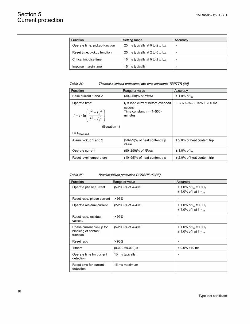
Function Setting range AccuracyOperate time, pickup function 25 ms typically at 0 to 2 x Iset -
Reset time, pickup function 25 ms typically at 2 to 0 x Iset -
Critical impulse time 10 ms typically at 0 to 2 x Iset -
Impulse margin time 15 ms typically -
Table 24: Thermal overload protection, two time constants TRPTTR (49)
Function Range or value AccuracyBase current 1 and 2 (30–250)% of IBase ± 1.0% of In
Operate time:
2 2
2 2ln p
b
I It
I It
æ ö-ç ÷= ×ç ÷-è ø
EQUATION1356 V1 EN (Equation 1)
I = Imeasured
Ip = load current before overloadoccursTime constant τ = (1–500)minutes
IEC 60255–8, ±5% + 200 ms
Alarm pickup 1 and 2 (50–99)% of heat content tripvalue
± 2.0% of heat content trip
Operate current (50–250)% of IBase ± 1.0% of In
Reset level temperature (10–95)% of heat content trip ± 2.0% of heat content trip
Table 25: Breaker failure protection CCRBRF (50BF)
Function Range or value AccuracyOperate phase current (5-200)% of lBase ± 1.0% of In at I £ In
± 1.0% of I at I > In
Reset ratio, phase current > 95% -
Operate residual current (2-200)% of lBase ± 1.0% of In at I £ In± 1.0% of I at I > In
Reset ratio, residualcurrent
> 95% -
Phase current pickup forblocking of contactfunction
(5-200)% of lBase ± 1.0% of In at I £ In± 1.0% of I at I > In
Reset ratio > 95% -
Timers (0.000-60.000) s ± 0.5% ±10 ms
Operate time for currentdetection
10 ms typically -
Reset time for currentdetection
15 ms maximum -
Section 5 1MRK505212-TUS DCurrent protection
18Type test certificate
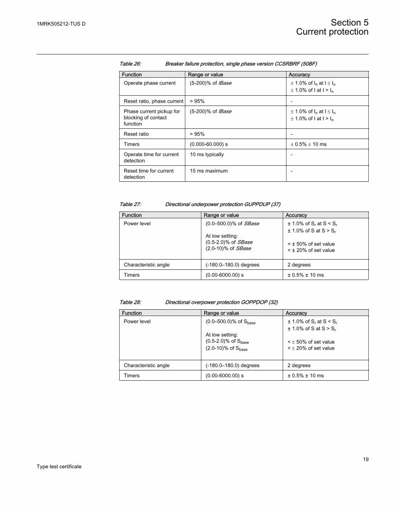
Table 26: Breaker failure protection, single phase version CCSRBRF (50BF)
Function Range or value AccuracyOperate phase current (5-200)% of lBase ± 1.0% of In at I £ In
± 1.0% of I at I > In
Reset ratio, phase current > 95% -
Phase current pickup forblocking of contactfunction
(5-200)% of lBase ± 1.0% of In at I £ In± 1.0% of I at I > In
Reset ratio > 95% -
Timers (0.000-60.000) s ± 0.5% ± 10 ms
Operate time for currentdetection
10 ms typically -
Reset time for currentdetection
15 ms maximum -
Table 27: Directional underpower protection GUPPDUP (37)
Function Range or value AccuracyPower level (0.0–500.0)% of SBase
At low setting:(0.5-2.0)% of SBase(2.0-10)% of SBase
± 1.0% of Sr at S < Sr± 1.0% of S at S > Sr < ± 50% of set value< ± 20% of set value
Characteristic angle (-180.0–180.0) degrees 2 degrees
Timers (0.00-6000.00) s ± 0.5% ± 10 ms
Table 28: Directional overpower protection GOPPDOP (32)
Function Range or value AccuracyPower level (0.0–500.0)% of Sbase
At low setting:(0.5-2.0)% of Sbase(2.0-10)% of Sbase
± 1.0% of Sr at S < Sr± 1.0% of S at S > Sr < ± 50% of set value< ± 20% of set value
Characteristic angle (-180.0–180.0) degrees 2 degrees
Timers (0.00-6000.00) s ± 0.5% ± 10 ms
1MRK505212-TUS D Section 5Current protection
19Type test certificate
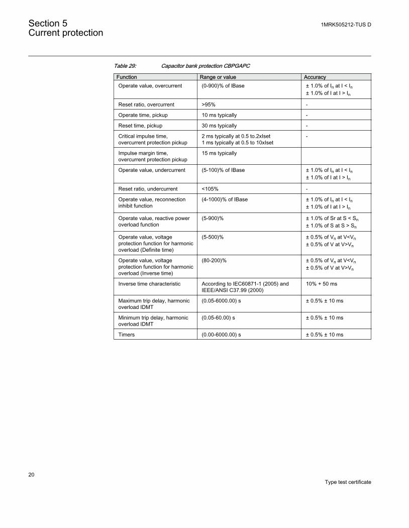
Table 29: Capacitor bank protection CBPGAPC
Function Range or value AccuracyOperate value, overcurrent (0-900)% of lBase ± 1.0% of In at I < In
± 1.0% of I at I > In
Reset ratio, overcurrent >95% -
Operate time, pickup 10 ms typically -
Reset time, pickup 30 ms typically -
Critical impulse time,overcurrent protection pickup
2 ms typically at 0.5 to.2xIset1 ms typically at 0.5 to 10xIset
-
Impulse margin time,overcurrent protection pickup
15 ms typically
Operate value, undercurrent (5-100)% of IBase ± 1.0% of In at I < In± 1.0% of I at I > In
Reset ratio, undercurrent <105% -
Operate value, reconnectioninhibit function
(4-1000)% of IBase ± 1.0% of In at I < In± 1.0% of I at I > In
Operate value, reactive poweroverload function
(5-900)% ± 1.0% of Sr at S < Sn± 1.0% of S at S > Sn
Operate value, voltageprotection function for harmonicoverload (Definite time)
(5-500)% ± 0.5% of Vn at V<Vn± 0.5% of V at V>Vn
Operate value, voltageprotection function for harmonicoverload (Inverse time)
(80-200)% ± 0.5% of Vn at V<Vn± 0.5% of V at V>Vn
Inverse time characteristic According to IEC60871-1 (2005) andIEEE/ANSI C37.99 (2000)
10% + 50 ms
Maximum trip delay, harmonicoverload IDMT
(0.05-6000.00) s ± 0.5% ± 10 ms
Minimum trip delay, harmonicoverload IDMT
(0.05-60.00) s ± 0.5% ± 10 ms
Timers (0.00-6000.00) s ± 0.5% ± 10 ms
Section 5 1MRK505212-TUS DCurrent protection
20Type test certificate
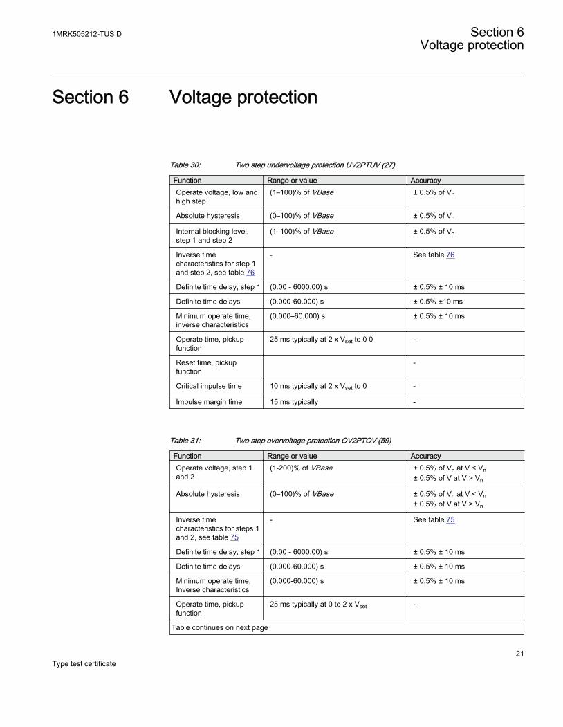
Section 6 Voltage protection
Table 30: Two step undervoltage protection UV2PTUV (27)
Function Range or value AccuracyOperate voltage, low andhigh step
(1–100)% of VBase ± 0.5% of Vn
Absolute hysteresis (0–100)% of VBase ± 0.5% of Vn
Internal blocking level,step 1 and step 2
(1–100)% of VBase ± 0.5% of Vn
Inverse timecharacteristics for step 1and step 2, see table 76
- See table 76
Definite time delay, step 1 (0.00 - 6000.00) s ± 0.5% ± 10 ms
Definite time delays (0.000-60.000) s ± 0.5% ±10 ms
Minimum operate time,inverse characteristics
(0.000–60.000) s ± 0.5% ± 10 ms
Operate time, pickupfunction
25 ms typically at 2 x Vset to 0 0 -
Reset time, pickupfunction
-
Critical impulse time 10 ms typically at 2 x Vset to 0 -
Impulse margin time 15 ms typically -
Table 31: Two step overvoltage protection OV2PTOV (59)
Function Range or value AccuracyOperate voltage, step 1and 2
(1-200)% of VBase ± 0.5% of Vn at V < Vn± 0.5% of V at V > Vn
Absolute hysteresis (0–100)% of VBase ± 0.5% of Vn at V < Vn± 0.5% of V at V > Vn
Inverse timecharacteristics for steps 1and 2, see table 75
- See table 75
Definite time delay, step 1 (0.00 - 6000.00) s ± 0.5% ± 10 ms
Definite time delays (0.000-60.000) s ± 0.5% ± 10 ms
Minimum operate time,Inverse characteristics
(0.000-60.000) s ± 0.5% ± 10 ms
Operate time, pickupfunction
25 ms typically at 0 to 2 x Vset -
Table continues on next page
1MRK505212-TUS D Section 6Voltage protection
21Type test certificate
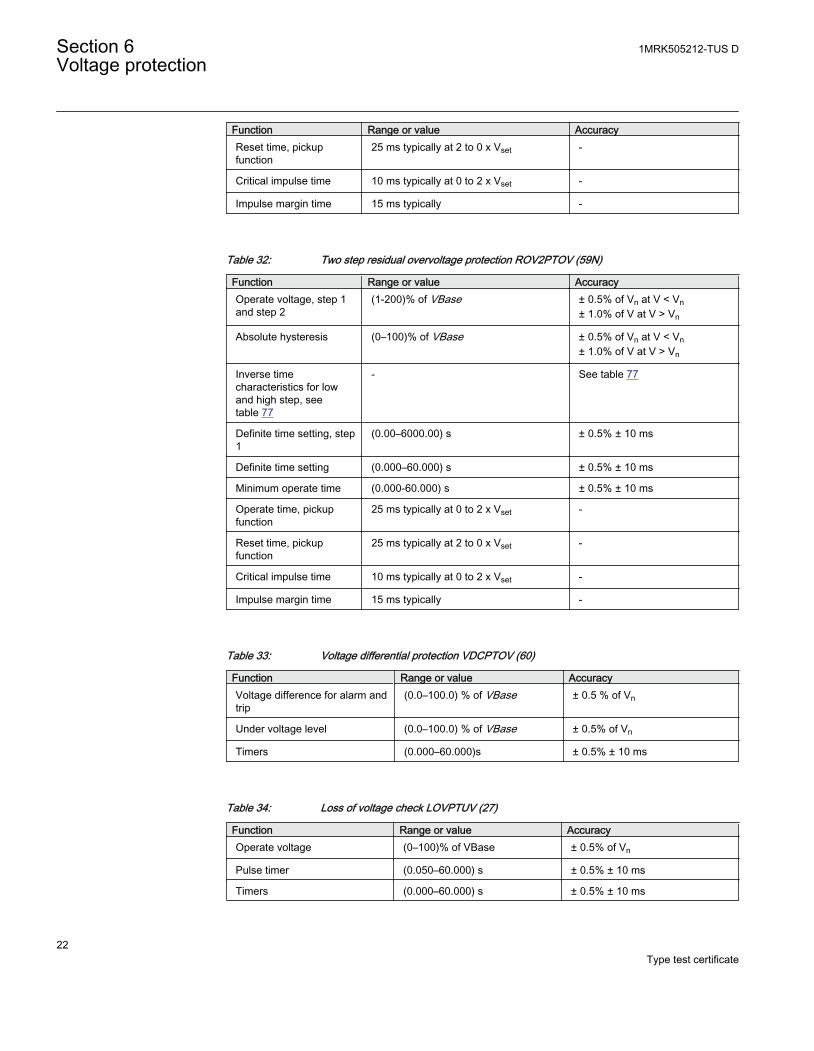
Function Range or value AccuracyReset time, pickupfunction
25 ms typically at 2 to 0 x Vset -
Critical impulse time 10 ms typically at 0 to 2 x Vset -
Impulse margin time 15 ms typically -
Table 32: Two step residual overvoltage protection ROV2PTOV (59N)
Function Range or value AccuracyOperate voltage, step 1and step 2
(1-200)% of VBase ± 0.5% of Vn at V < Vn± 1.0% of V at V > Vn
Absolute hysteresis (0–100)% of VBase ± 0.5% of Vn at V < Vn± 1.0% of V at V > Vn
Inverse timecharacteristics for lowand high step, seetable 77
- See table 77
Definite time setting, step1
(0.00–6000.00) s ± 0.5% ± 10 ms
Definite time setting (0.000–60.000) s ± 0.5% ± 10 ms
Minimum operate time (0.000-60.000) s ± 0.5% ± 10 ms
Operate time, pickupfunction
25 ms typically at 0 to 2 x Vset -
Reset time, pickupfunction
25 ms typically at 2 to 0 x Vset -
Critical impulse time 10 ms typically at 0 to 2 x Vset -
Impulse margin time 15 ms typically -
Table 33: Voltage differential protection VDCPTOV (60)
Function Range or value AccuracyVoltage difference for alarm andtrip
(0.0–100.0) % of VBase ± 0.5 % of Vn
Under voltage level (0.0–100.0) % of VBase ± 0.5% of Vn
Timers (0.000–60.000)s ± 0.5% ± 10 ms
Table 34: Loss of voltage check LOVPTUV (27)
Function Range or value AccuracyOperate voltage (0–100)% of VBase ± 0.5% of Vn
Pulse timer (0.050–60.000) s ± 0.5% ± 10 ms
Timers (0.000–60.000) s ± 0.5% ± 10 ms
Section 6 1MRK505212-TUS DVoltage protection
22Type test certificate
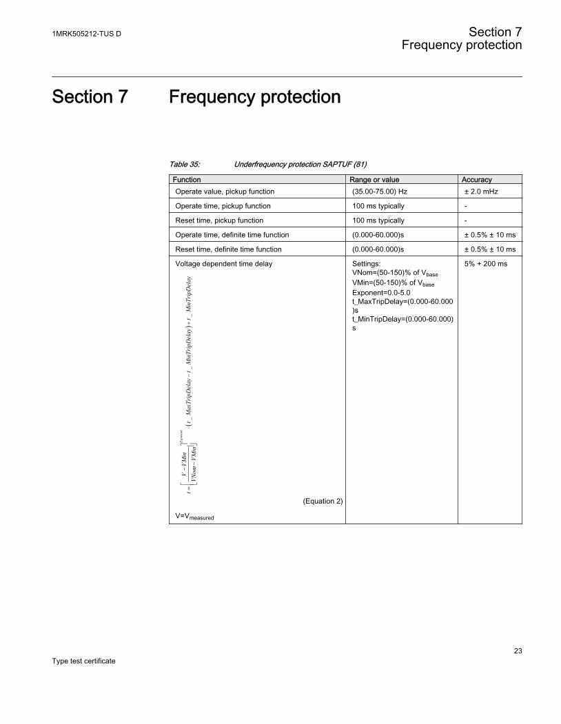
Section 7 Frequency protection
Table 35: Underfrequency protection SAPTUF (81)
Function Range or value AccuracyOperate value, pickup function (35.00-75.00) Hz ± 2.0 mHz
Operate time, pickup function 100 ms typically -
Reset time, pickup function 100 ms typically -
Operate time, definite time function (0.000-60.000)s ± 0.5% ± 10 ms
Reset time, definite time function (0.000-60.000)s ± 0.5% ± 10 ms
Voltage dependent time delay
()
__
_Exponent
VVM
int
tMaxTripDelay
tMinTripDelay
tMinTripDelay
VNom
VMin
-=
×-
+-
éù
êú
ëû
EQUATION1559 V1 EN (Equation 2)
V=Vmeasured
Settings:VNom=(50-150)% of VbaseVMin=(50-150)% of VbaseExponent=0.0-5.0t_MaxTripDelay=(0.000-60.000)st_MinTripDelay=(0.000-60.000)s
5% + 200 ms
1MRK505212-TUS D Section 7Frequency protection
23Type test certificate
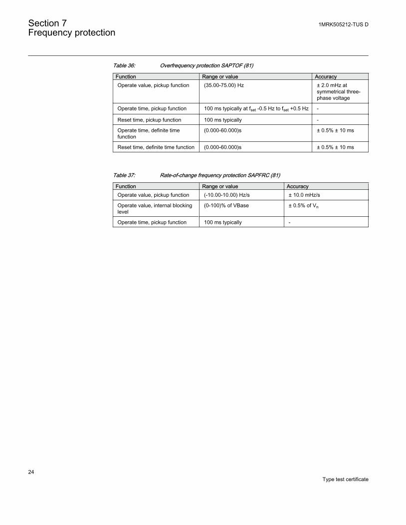
Table 36: Overfrequency protection SAPTOF (81)
Function Range or value AccuracyOperate value, pickup function (35.00-75.00) Hz ± 2.0 mHz at
symmetrical three-phase voltage
Operate time, pickup function 100 ms typically at fset -0.5 Hz to fset +0.5 Hz -
Reset time, pickup function 100 ms typically -
Operate time, definite timefunction
(0.000-60.000)s ± 0.5% ± 10 ms
Reset time, definite time function (0.000-60.000)s ± 0.5% ± 10 ms
Table 37: Rate-of-change frequency protection SAPFRC (81)
Function Range or value AccuracyOperate value, pickup function (-10.00-10.00) Hz/s ± 10.0 mHz/s
Operate value, internal blockinglevel
(0-100)% of VBase ± 0.5% of Vn
Operate time, pickup function 100 ms typically -
Section 7 1MRK505212-TUS DFrequency protection
24Type test certificate
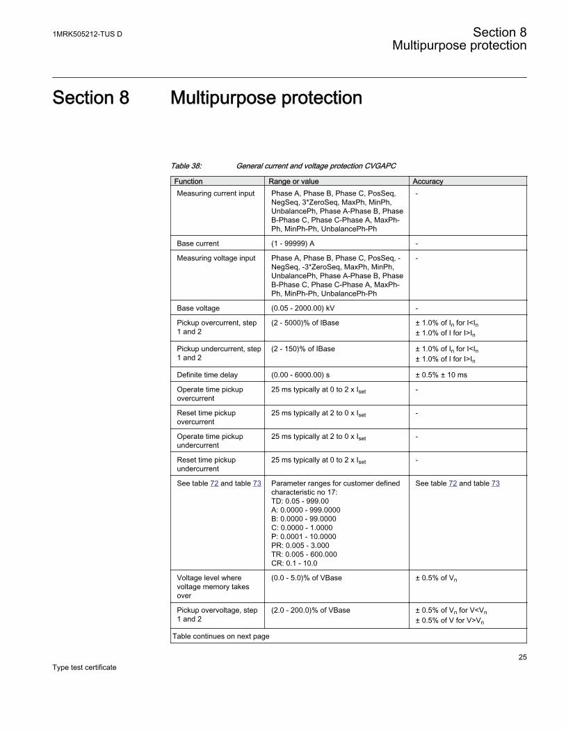
Section 8 Multipurpose protection
Table 38: General current and voltage protection CVGAPC
Function Range or value AccuracyMeasuring current input Phase A, Phase B, Phase C, PosSeq,
NegSeq, 3*ZeroSeq, MaxPh, MinPh,UnbalancePh, Phase A-Phase B, PhaseB-Phase C, Phase C-Phase A, MaxPh-Ph, MinPh-Ph, UnbalancePh-Ph
-
Base current (1 - 99999) A -
Measuring voltage input Phase A, Phase B, Phase C, PosSeq, -NegSeq, -3*ZeroSeq, MaxPh, MinPh,UnbalancePh, Phase A-Phase B, PhaseB-Phase C, Phase C-Phase A, MaxPh-Ph, MinPh-Ph, UnbalancePh-Ph
-
Base voltage (0.05 - 2000.00) kV -
Pickup overcurrent, step1 and 2
(2 - 5000)% of IBase ± 1.0% of In for I<In± 1.0% of I for I>In
Pickup undercurrent, step1 and 2
(2 - 150)% of IBase ± 1.0% of In for I<In± 1.0% of I for I>In
Definite time delay (0.00 - 6000.00) s ± 0.5% ± 10 ms
Operate time pickupovercurrent
25 ms typically at 0 to 2 x Iset -
Reset time pickupovercurrent
25 ms typically at 2 to 0 x Iset -
Operate time pickupundercurrent
25 ms typically at 2 to 0 x Iset -
Reset time pickupundercurrent
25 ms typically at 0 to 2 x Iset -
See table 72 and table 73 Parameter ranges for customer definedcharacteristic no 17:TD: 0.05 - 999.00A: 0.0000 - 999.0000B: 0.0000 - 99.0000C: 0.0000 - 1.0000P: 0.0001 - 10.0000PR: 0.005 - 3.000TR: 0.005 - 600.000CR: 0.1 - 10.0
See table 72 and table 73
Voltage level wherevoltage memory takesover
(0.0 - 5.0)% of VBase ± 0.5% of Vn
Pickup overvoltage, step1 and 2
(2.0 - 200.0)% of VBase ± 0.5% of Vn for V<Vn± 0.5% of V for V>Vn
Table continues on next page
1MRK505212-TUS D Section 8Multipurpose protection
25Type test certificate
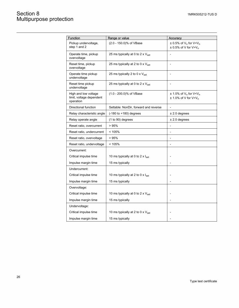
Function Range or value AccuracyPickup undervoltage,step 1 and 2
(2.0 - 150.0)% of VBase ± 0.5% of Vn for V<Vn± 0.5% of V for V>Vn
Operate time, pickupovervoltage
25 ms typically at 0 to 2 x Vset -
Reset time, pickupovervoltage
25 ms typically at 2 to 0 x Vset -
Operate time pickupundervoltage
25 ms typically 2 to 0 x Vset -
Reset time pickupundervoltage
25 ms typically at 0 to 2 x Vset -
High and low voltagelimit, voltage dependentoperation
(1.0 - 200.0)% of VBase ± 1.0% of Vn for V<Vn± 1.0% of V for V>Vn
Directional function Settable: NonDir, forward and reverse -
Relay characteristic angle (-180 to +180) degrees ± 2.0 degrees
Relay operate angle (1 to 90) degrees ± 2.0 degrees
Reset ratio, overcurrent > 95% -
Reset ratio, undercurrent < 105% -
Reset ratio, overvoltage > 95% -
Reset ratio, undervoltage < 105% -
Overcurrent:
Critical impulse time 10 ms typically at 0 to 2 x Iset -
Impulse margin time 15 ms typically -
Undercurrent:
Critical impulse time 10 ms typically at 2 to 0 x Iset -
Impulse margin time 15 ms typically -
Overvoltage:
Critical impulse time 10 ms typically at 0 to 2 x Vset -
Impulse margin time 15 ms typically -
Undervoltage:
Critical impulse time 10 ms typically at 2 to 0 x Vset -
Impulse margin time 15 ms typically -
Section 8 1MRK505212-TUS DMultipurpose protection
26Type test certificate
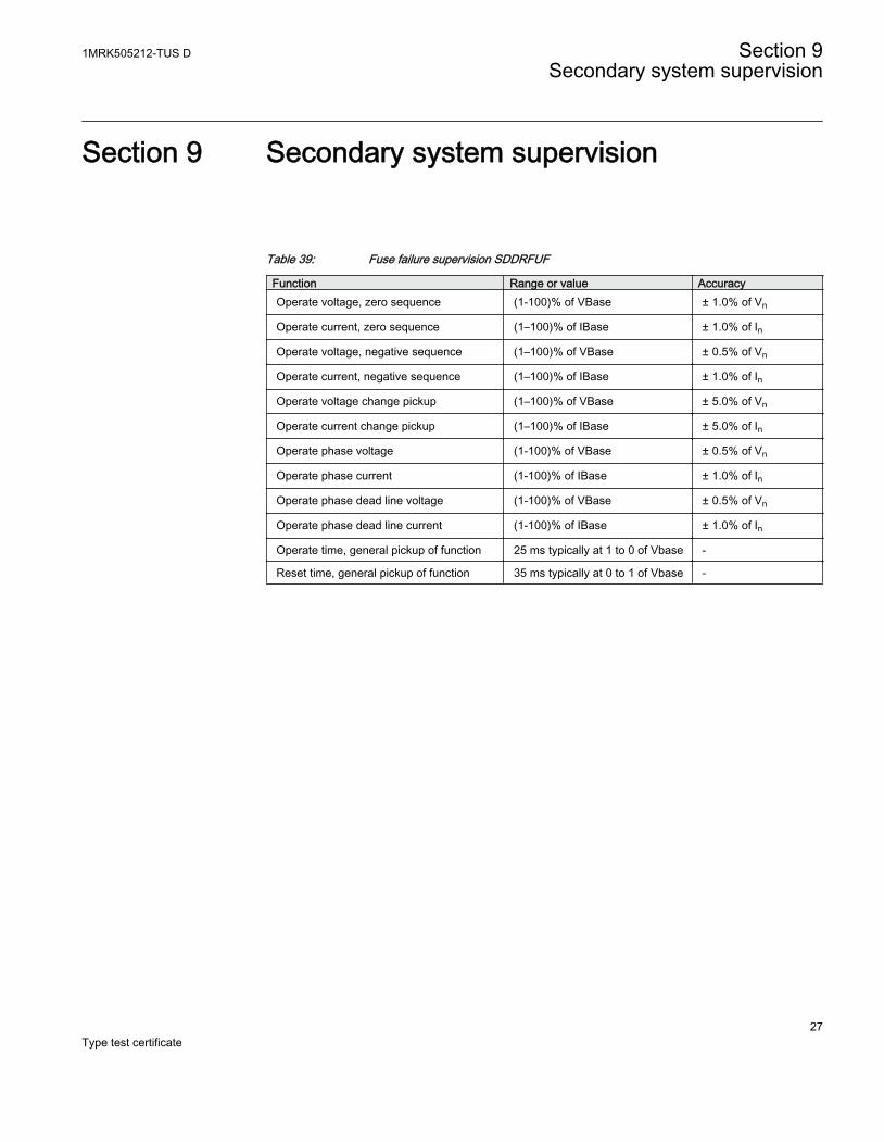
Section 9 Secondary system supervision
Table 39: Fuse failure supervision SDDRFUF
Function Range or value AccuracyOperate voltage, zero sequence (1-100)% of VBase ± 1.0% of Vn
Operate current, zero sequence (1–100)% of IBase ± 1.0% of In
Operate voltage, negative sequence (1–100)% of VBase ± 0.5% of Vn
Operate current, negative sequence (1–100)% of IBase ± 1.0% of In
Operate voltage change pickup (1–100)% of VBase ± 5.0% of Vn
Operate current change pickup (1–100)% of IBase ± 5.0% of In
Operate phase voltage (1-100)% of VBase ± 0.5% of Vn
Operate phase current (1-100)% of IBase ± 1.0% of In
Operate phase dead line voltage (1-100)% of VBase ± 0.5% of Vn
Operate phase dead line current (1-100)% of IBase ± 1.0% of In
Operate time, general pickup of function 25 ms typically at 1 to 0 of Vbase -
Reset time, general pickup of function 35 ms typically at 0 to 1 of Vbase -
1MRK505212-TUS D Section 9Secondary system supervision
27Type test certificate

28
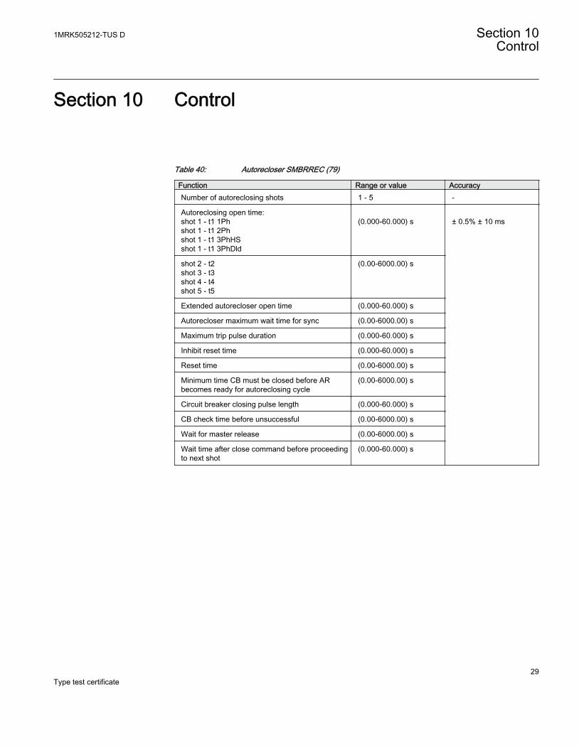
Section 10 Control
Table 40: Autorecloser SMBRREC (79)
Function Range or value AccuracyNumber of autoreclosing shots 1 - 5 -
Autoreclosing open time:shot 1 - t1 1Phshot 1 - t1 2Phshot 1 - t1 3PhHSshot 1 - t1 3PhDld
(0.000-60.000) s
± 0.5% ± 10 ms
shot 2 - t2shot 3 - t3shot 4 - t4shot 5 - t5
(0.00-6000.00) s
Extended autorecloser open time (0.000-60.000) s
Autorecloser maximum wait time for sync (0.00-6000.00) s
Maximum trip pulse duration (0.000-60.000) s
Inhibit reset time (0.000-60.000) s
Reset time (0.00-6000.00) s
Minimum time CB must be closed before ARbecomes ready for autoreclosing cycle
(0.00-6000.00) s
Circuit breaker closing pulse length (0.000-60.000) s
CB check time before unsuccessful (0.00-6000.00) s
Wait for master release (0.00-6000.00) s
Wait time after close command before proceedingto next shot
(0.000-60.000) s
1MRK505212-TUS D Section 10Control
29Type test certificate

30
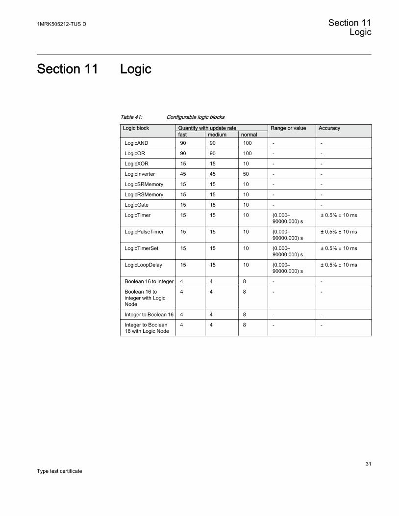
Section 11 Logic
Table 41: Configurable logic blocks
Logic block Quantity with update rate Range or value Accuracyfast medium normal
LogicAND 90 90 100 - -
LogicOR 90 90 100 - -
LogicXOR 15 15 10 - -
LogicInverter 45 45 50 - -
LogicSRMemory 15 15 10 - -
LogicRSMemory 15 15 10 - -
LogicGate 15 15 10 - -
LogicTimer 15 15 10 (0.000–90000.000) s
± 0.5% ± 10 ms
LogicPulseTimer 15 15 10 (0.000–90000.000) s
± 0.5% ± 10 ms
LogicTimerSet 15 15 10 (0.000–90000.000) s
± 0.5% ± 10 ms
LogicLoopDelay 15 15 10 (0.000–90000.000) s
± 0.5% ± 10 ms
Boolean 16 to Integer 4 4 8 - -
Boolean 16 tointeger with LogicNode
4 4 8 - -
Integer to Boolean 16 4 4 8 - -
Integer to Boolean16 with Logic Node
4 4 8 - -
1MRK505212-TUS D Section 11Logic
31Type test certificate

32
Section 12 Monitoring
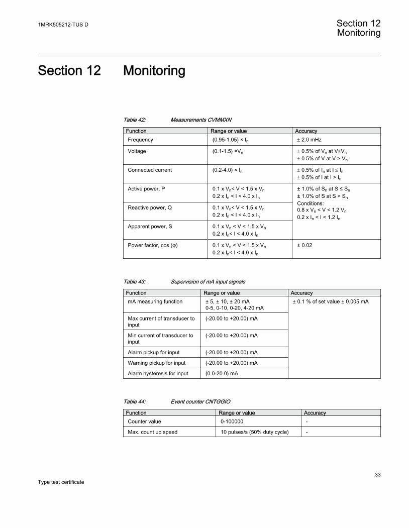
Table 42: Measurements CVMMXN
Function Range or value AccuracyFrequency (0.95-1.05) × fn ± 2.0 mHz
Voltage (0.1-1.5) ×Vn ± 0.5% of Vn at V£Vn± 0.5% of V at V > Vn
Connected current (0.2-4.0) × In ± 0.5% of In at I £ In± 0.5% of I at I > In
Active power, P 0.1 x Vn< V < 1.5 x Vn0.2 x In < I < 4.0 x In
± 1.0% of Sn at S ≤ Sn± 1.0% of S at S > SnConditions:0.8 x Vn < V < 1.2 Vn0.2 x In < I < 1.2 In
Reactive power, Q 0.1 x Vn< V < 1.5 x Vn0.2 x In < I < 4.0 x In
Apparent power, S 0.1 x Vn < V < 1.5 x Vn0.2 x In< I < 4.0 x In
Power factor, cos (φ) 0.1 x Vn < V < 1.5 x Vn0.2 x In< I < 4.0 x In
± 0.02
Table 43: Supervision of mA input signals
Function Range or value AccuracymA measuring function ± 5, ± 10, ± 20 mA
0-5, 0-10, 0-20, 4-20 mA± 0.1 % of set value ± 0.005 mA
Max current of transducer toinput
(-20.00 to +20.00) mA
Min current of transducer toinput
(-20.00 to +20.00) mA
Alarm pickup for input (-20.00 to +20.00) mA
Warning pickup for input (-20.00 to +20.00) mA
Alarm hysteresis for input (0.0-20.0) mA
Table 44: Event counter CNTGGIO
Function Range or value AccuracyCounter value 0-100000 -
Max. count up speed 10 pulses/s (50% duty cycle) -
1MRK505212-TUS D Section 12Monitoring
33Type test certificate
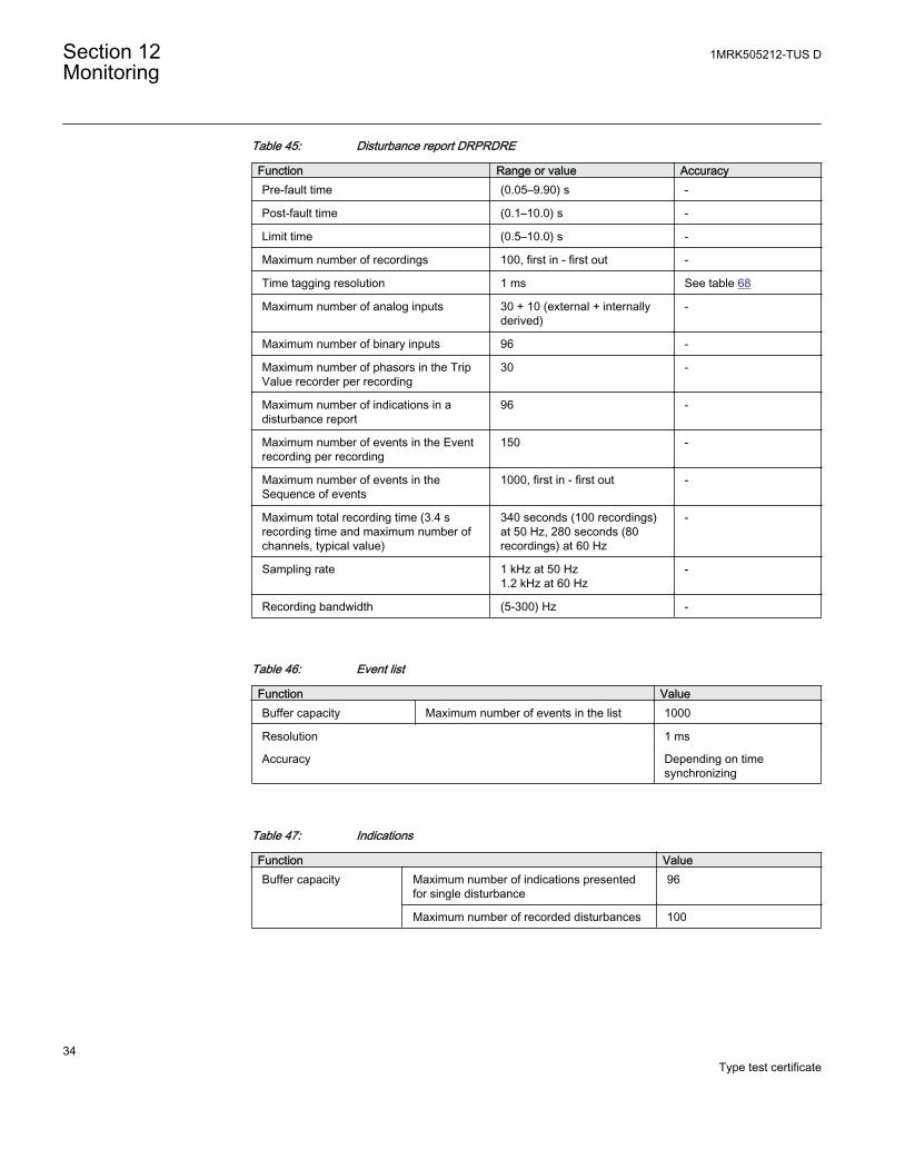
Table 45: Disturbance report DRPRDRE
Function Range or value AccuracyPre-fault time (0.05–9.90) s -
Post-fault time (0.1–10.0) s -
Limit time (0.5–10.0) s -
Maximum number of recordings 100, first in - first out -
Time tagging resolution 1 ms See table 68
Maximum number of analog inputs 30 + 10 (external + internallyderived)
-
Maximum number of binary inputs 96 -
Maximum number of phasors in the TripValue recorder per recording
30 -
Maximum number of indications in adisturbance report
96 -
Maximum number of events in the Eventrecording per recording
150 -
Maximum number of events in theSequence of events
1000, first in - first out -
Maximum total recording time (3.4 srecording time and maximum number ofchannels, typical value)
340 seconds (100 recordings)at 50 Hz, 280 seconds (80recordings) at 60 Hz
-
Sampling rate 1 kHz at 50 Hz1.2 kHz at 60 Hz
-
Recording bandwidth (5-300) Hz -
Table 46: Event list
Function ValueBuffer capacity Maximum number of events in the list 1000
Resolution 1 ms
Accuracy Depending on timesynchronizing
Table 47: Indications
Function ValueBuffer capacity Maximum number of indications presented
for single disturbance96
Maximum number of recorded disturbances 100
Section 12 1MRK505212-TUS DMonitoring
34Type test certificate
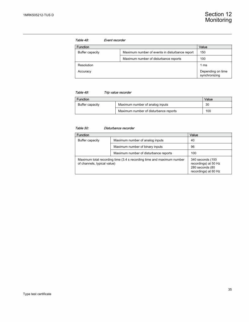
Table 48: Event recorder
Function ValueBuffer capacity Maximum number of events in disturbance report 150
Maximum number of disturbance reports 100
Resolution 1 ms
Accuracy Depending on timesynchronizing
Table 49: Trip value recorder
Function ValueBuffer capacity
Maximum number of analog inputs 30
Maximum number of disturbance reports 100
Table 50: Disturbance recorder
Function ValueBuffer capacity Maximum number of analog inputs 40
Maximum number of binary inputs 96
Maximum number of disturbance reports 100
Maximum total recording time (3.4 s recording time and maximum numberof channels, typical value)
340 seconds (100recordings) at 50 Hz280 seconds (80recordings) at 60 Hz
1MRK505212-TUS D Section 12Monitoring
35Type test certificate

36
Section 13 Metering
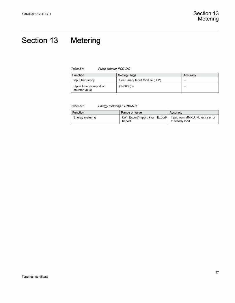
Table 51: Pulse counter PCGGIO
Function Setting range AccuracyInput frequency See Binary Input Module (BIM) -
Cycle time for report ofcounter value
(1–3600) s -
Table 52: Energy metering ETPMMTR
Function Range or value AccuracyEnergy metering kWh Export/Import, kvarh Export/
ImportInput from MMXU. No extra errorat steady load
1MRK505212-TUS D Section 13Metering
37Type test certificate

38
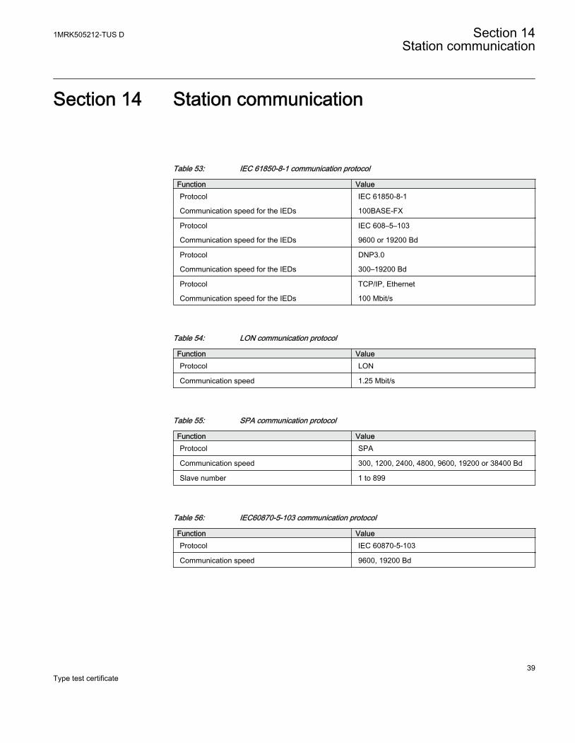
Section 14 Station communication
Table 53: IEC 61850-8-1 communication protocol
Function ValueProtocol IEC 61850-8-1
Communication speed for the IEDs 100BASE-FX
Protocol IEC 608–5–103
Communication speed for the IEDs 9600 or 19200 Bd
Protocol DNP3.0
Communication speed for the IEDs 300–19200 Bd
Protocol TCP/IP, Ethernet
Communication speed for the IEDs 100 Mbit/s
Table 54: LON communication protocol
Function ValueProtocol LON
Communication speed 1.25 Mbit/s
Table 55: SPA communication protocol
Function ValueProtocol SPA
Communication speed 300, 1200, 2400, 4800, 9600, 19200 or 38400 Bd
Slave number 1 to 899
Table 56: IEC60870-5-103 communication protocol
Function ValueProtocol IEC 60870-5-103
Communication speed 9600, 19200 Bd
1MRK505212-TUS D Section 14Station communication
39Type test certificate
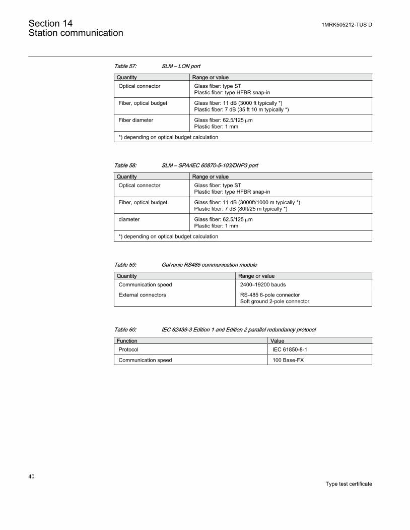
Table 57: SLM – LON port
Quantity Range or valueOptical connector Glass fiber: type ST
Plastic fiber: type HFBR snap-in
Fiber, optical budget Glass fiber: 11 dB (3000 ft typically *)Plastic fiber: 7 dB (35 ft 10 m typically *)
Fiber diameter Glass fiber: 62.5/125 mmPlastic fiber: 1 mm
*) depending on optical budget calculation
Table 58: SLM – SPA/IEC 60870-5-103/DNP3 port
Quantity Range or valueOptical connector Glass fiber: type ST
Plastic fiber: type HFBR snap-in
Fiber, optical budget Glass fiber: 11 dB (3000ft/1000 m typically *)Plastic fiber: 7 dB (80ft/25 m typically *)
diameter Glass fiber: 62.5/125 mmPlastic fiber: 1 mm
*) depending on optical budget calculation
Table 59: Galvanic RS485 communication module
Quantity Range or valueCommunication speed 2400–19200 bauds
External connectors RS-485 6-pole connectorSoft ground 2-pole connector
Table 60: IEC 62439-3 Edition 1 and Edition 2 parallel redundancy protocol
Function ValueProtocol IEC 61850-8-1
Communication speed 100 Base-FX
Section 14 1MRK505212-TUS DStation communication
40Type test certificate
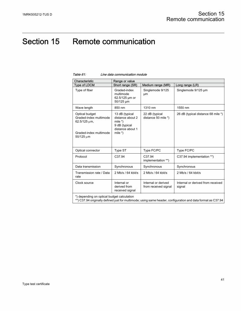
Section 15 Remote communication
Table 61: Line data communication module
Characteristic Range or valueType of LDCM Short range (SR) Medium range (MR) Long range (LR)Type of fiber Graded-index
multimode62.5/125 µm or50/125 µm
Singlemode 9/125µm
Singlemode 9/125 µm
Wave length 850 nm 1310 nm 1550 nm
Optical budgetGraded-index multimode62.5/125 mm, Graded-index multimode50/125 mm
13 dB (typicaldistance about 2mile *)9 dB (typicaldistance about 1mile *)
22 dB (typicaldistance 50 mile *)
26 dB (typical distance 68 mile *)
Optical connector Type ST Type FC/PC Type FC/PC
Protocol C37.94 C37.94implementation **)
C37.94 implementation **)
Data transmission Synchronous Synchronous Synchronous
Transmission rate / Datarate
2 Mb/s / 64 kbit/s 2 Mb/s / 64 kbit/s 2 Mb/s / 64 kbit/s
Clock source Internal orderived fromreceived signal
Internal or derivedfrom received signal
Internal or derived from receivedsignal
*) depending on optical budget calculation**) C37.94 originally defined just for multimode; using same header, configuration and data format as C37.94
1MRK505212-TUS D Section 15Remote communication
41Type test certificate

42
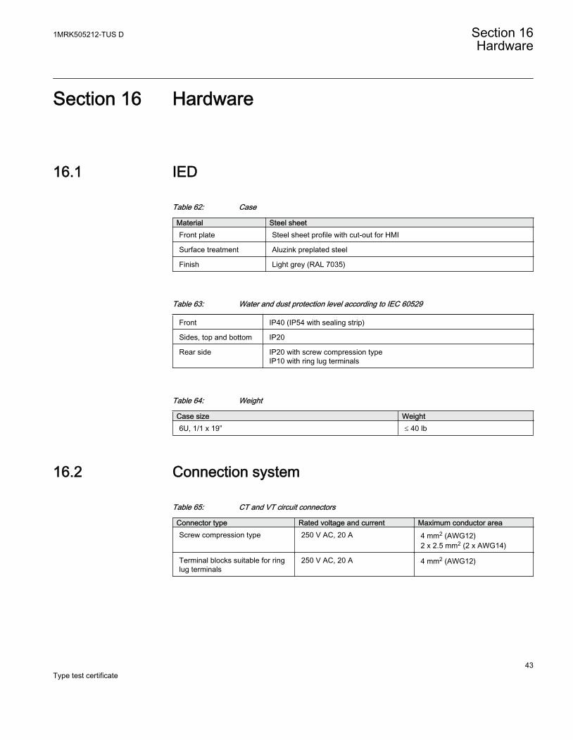
Section 16 Hardware
16.1 IED
Table 62: Case
Material Steel sheetFront plate Steel sheet profile with cut-out for HMI
Surface treatment Aluzink preplated steel
Finish Light grey (RAL 7035)
Table 63: Water and dust protection level according to IEC 60529
Front IP40 (IP54 with sealing strip)
Sides, top and bottom IP20
Rear side IP20 with screw compression typeIP10 with ring lug terminals
Table 64: Weight
Case size Weight6U, 1/1 x 19” £ 40 lb
16.2 Connection system
Table 65: CT and VT circuit connectors
Connector type Rated voltage and current Maximum conductor areaScrew compression type 250 V AC, 20 A 4 mm2 (AWG12)
2 x 2.5 mm2 (2 x AWG14)
Terminal blocks suitable for ringlug terminals
250 V AC, 20 A 4 mm2 (AWG12)
1MRK505212-TUS D Section 16Hardware
43Type test certificate
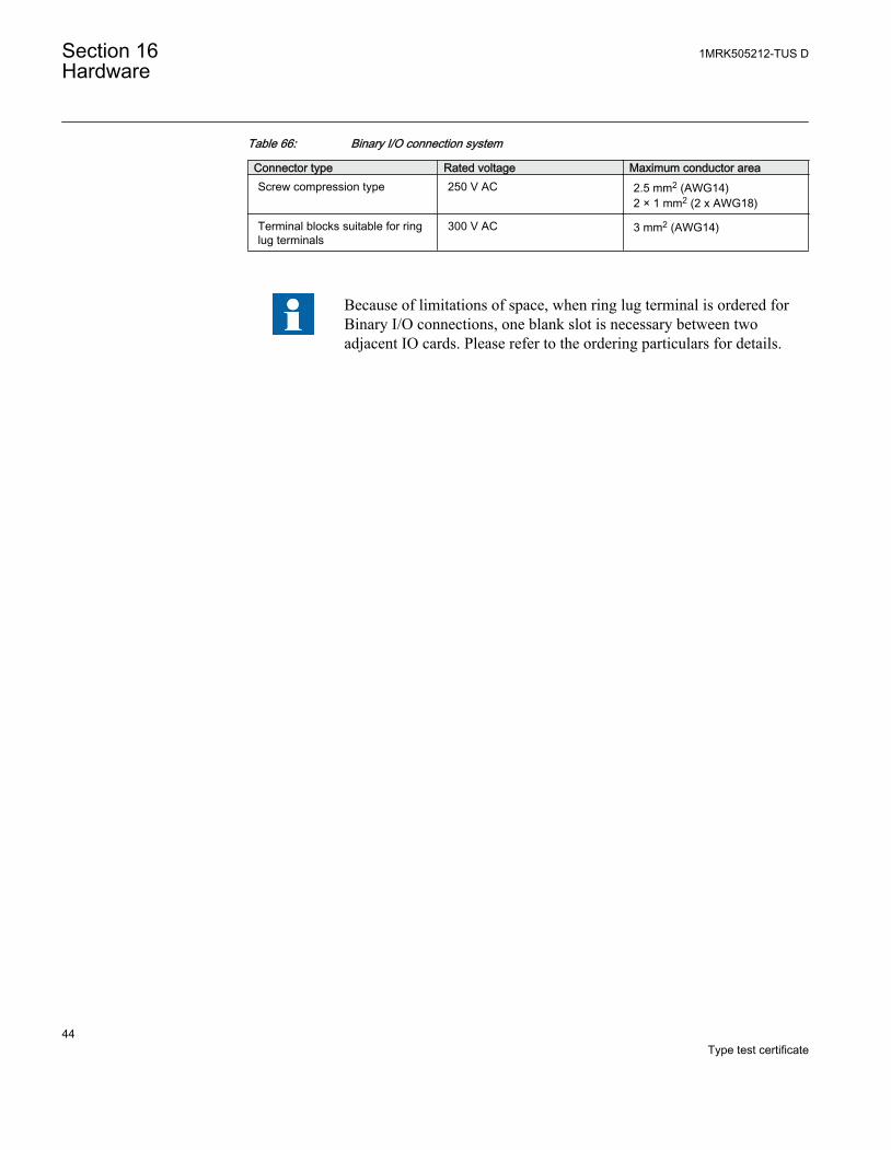
Table 66: Binary I/O connection system
Connector type Rated voltage Maximum conductor areaScrew compression type 250 V AC 2.5 mm2 (AWG14)
2 × 1 mm2 (2 x AWG18)
Terminal blocks suitable for ringlug terminals
300 V AC 3 mm2 (AWG14)
Because of limitations of space, when ring lug terminal is ordered forBinary I/O connections, one blank slot is necessary between twoadjacent IO cards. Please refer to the ordering particulars for details.
Section 16 1MRK505212-TUS DHardware
44Type test certificate
Section 17 Basic IED functions
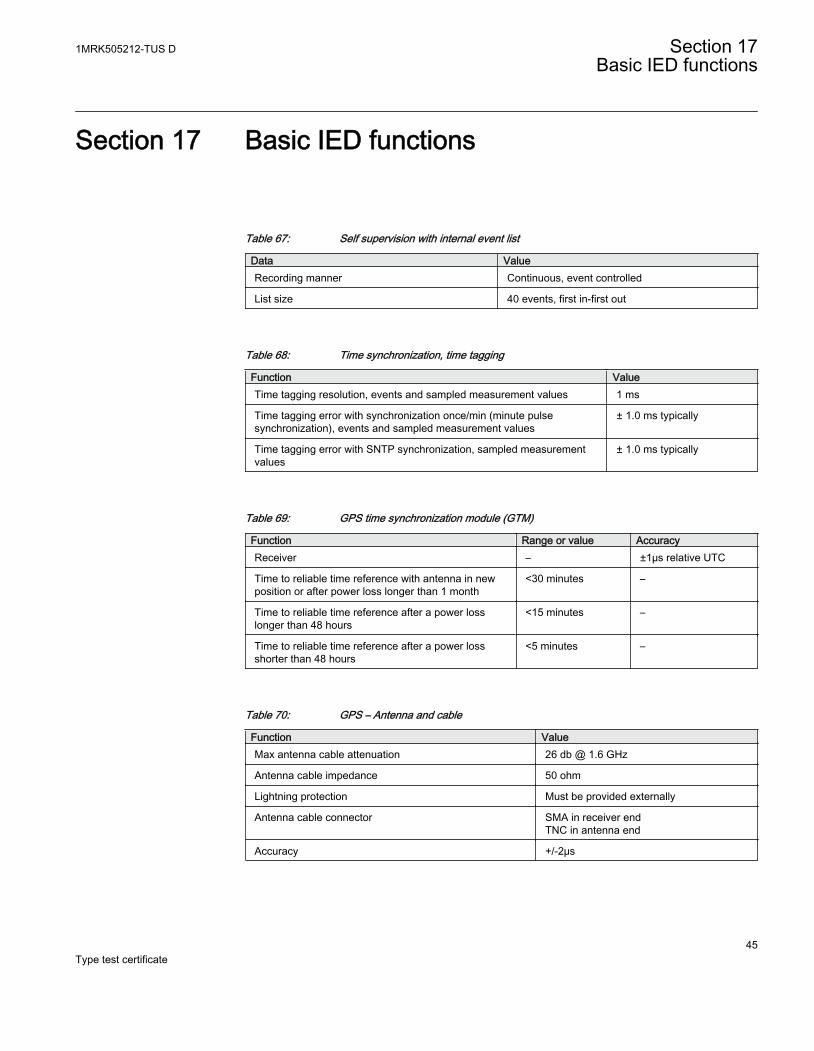
Table 67: Self supervision with internal event list
Data ValueRecording manner Continuous, event controlled
List size 40 events, first in-first out
Table 68: Time synchronization, time tagging
Function ValueTime tagging resolution, events and sampled measurement values 1 ms
Time tagging error with synchronization once/min (minute pulsesynchronization), events and sampled measurement values
± 1.0 ms typically
Time tagging error with SNTP synchronization, sampled measurementvalues
± 1.0 ms typically
Table 69: GPS time synchronization module (GTM)
Function Range or value AccuracyReceiver – ±1µs relative UTC
Time to reliable time reference with antenna in newposition or after power loss longer than 1 month
<30 minutes –
Time to reliable time reference after a power losslonger than 48 hours
<15 minutes –
Time to reliable time reference after a power lossshorter than 48 hours
<5 minutes –
Table 70: GPS – Antenna and cable
Function ValueMax antenna cable attenuation 26 db @ 1.6 GHz
Antenna cable impedance 50 ohm
Lightning protection Must be provided externally
Antenna cable connector SMA in receiver endTNC in antenna end
Accuracy +/-2μs
1MRK505212-TUS D Section 17Basic IED functions
45Type test certificate
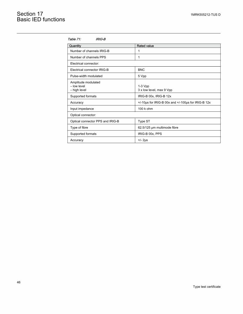
Table 71: IRIG-B
Quantity Rated valueNumber of channels IRIG-B 1
Number of channels PPS 1
Electrical connector:
Electrical connector IRIG-B BNC
Pulse-width modulated 5 Vpp
Amplitude modulated– low level– high level
1-3 Vpp3 x low level, max 9 Vpp
Supported formats IRIG-B 00x, IRIG-B 12x
Accuracy +/-10μs for IRIG-B 00x and +/-100μs for IRIG-B 12x
Input impedance 100 k ohm
Optical connector:
Optical connector PPS and IRIG-B Type ST
Type of fibre 62.5/125 μm multimode fibre
Supported formats IRIG-B 00x, PPS
Accuracy +/- 2μs
Section 17 1MRK505212-TUS DBasic IED functions
46Type test certificate
Section 18 Inverse characteristics
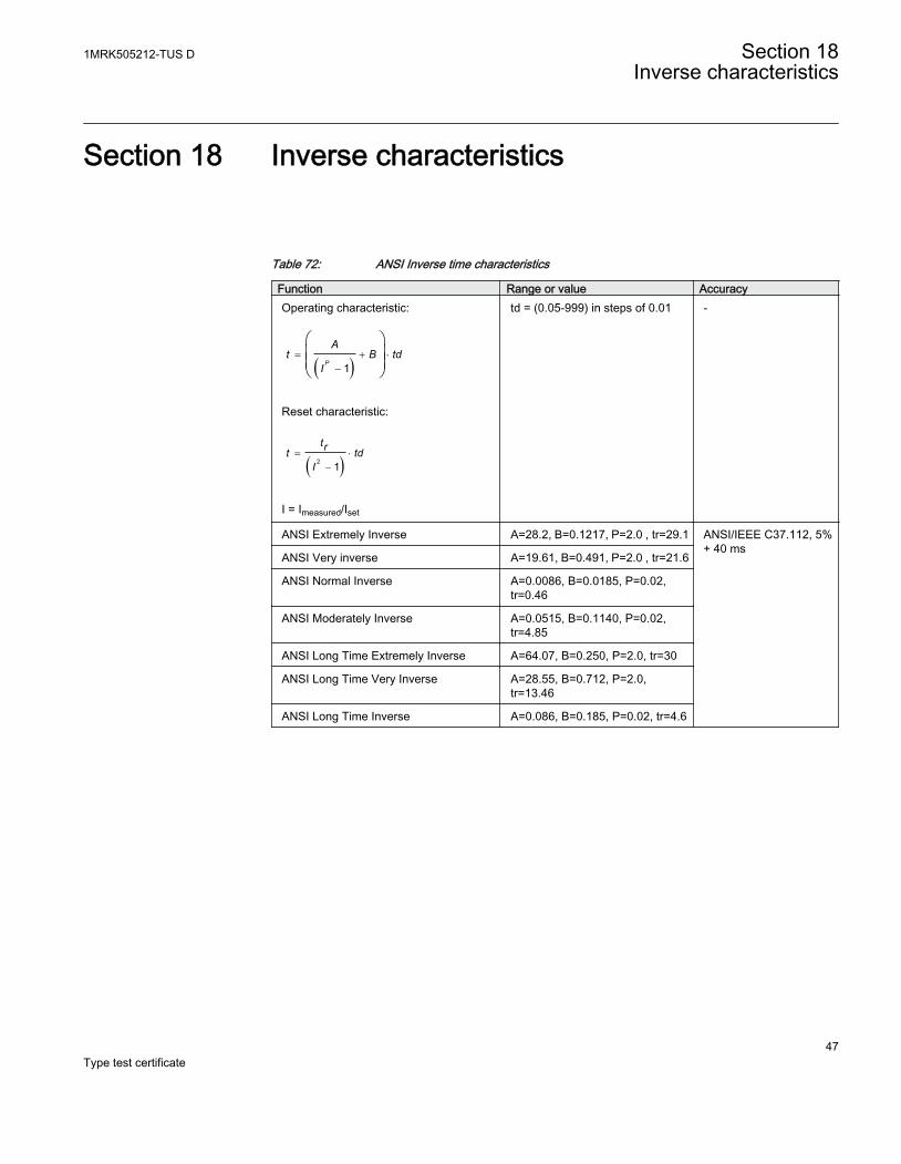
Table 72: ANSI Inverse time characteristics
Function Range or value AccuracyOperating characteristic:
( )= + ×
-
æ öç ÷ç ÷è ø1P
At B td
I
EQUATION1651 V1 EN
Reset characteristic:
( )= ×
-2 1
trt tdI
EQUATION1652 V1 EN
I = Imeasured/Iset
td = (0.05-999) in steps of 0.01 -
ANSI Extremely Inverse A=28.2, B=0.1217, P=2.0 , tr=29.1 ANSI/IEEE C37.112, 5%+ 40 ms
ANSI Very inverse A=19.61, B=0.491, P=2.0 , tr=21.6
ANSI Normal Inverse A=0.0086, B=0.0185, P=0.02,tr=0.46
ANSI Moderately Inverse A=0.0515, B=0.1140, P=0.02,tr=4.85
ANSI Long Time Extremely Inverse A=64.07, B=0.250, P=2.0, tr=30
ANSI Long Time Very Inverse A=28.55, B=0.712, P=2.0,tr=13.46
ANSI Long Time Inverse A=0.086, B=0.185, P=0.02, tr=4.6
1MRK505212-TUS D Section 18Inverse characteristics
47Type test certificate
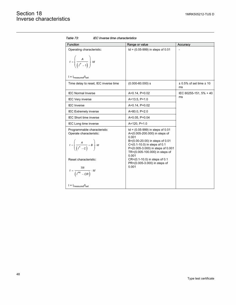
Table 73: IEC Inverse time characteristics
Function Range or value AccuracyOperating characteristic:
( )= ×
-
æ öç ÷ç ÷è ø1P
At td
I
EQUATION1653 V1 EN
I = Imeasured/Iset
td = (0.05-999) in steps of 0.01 -
Time delay to reset, IEC inverse time (0.000-60.000) s ± 0.5% of set time ± 10ms
IEC Normal Inverse A=0.14, P=0.02 IEC 60255-151, 5% + 40ms
IEC Very inverse A=13.5, P=1.0
IEC Inverse A=0.14, P=0.02
IEC Extremely inverse A=80.0, P=2.0
IEC Short time inverse A=0.05, P=0.04
IEC Long time inverse A=120, P=1.0
Programmable characteristicOperate characteristic:
( )= + ×
-
æ öç ÷ç ÷è ø
P
At B td
I C
EQUATION1654 V1 EN
Reset characteristic:
( )= ×
-PR
TRt td
I CR
EQUATION1655 V1 EN
I = Imeasured/Iset
td = (0.05-999) in steps of 0.01A=(0.005-200.000) in steps of0.001B=(0.00-20.00) in steps of 0.01C=(0.1-10.0) in steps of 0.1P=(0.005-3.000) in steps of 0.001TR=(0.005-100.000) in steps of0.001CR=(0.1-10.0) in steps of 0.1PR=(0.005-3.000) in steps of0.001
Section 18 1MRK505212-TUS DInverse characteristics
48Type test certificate
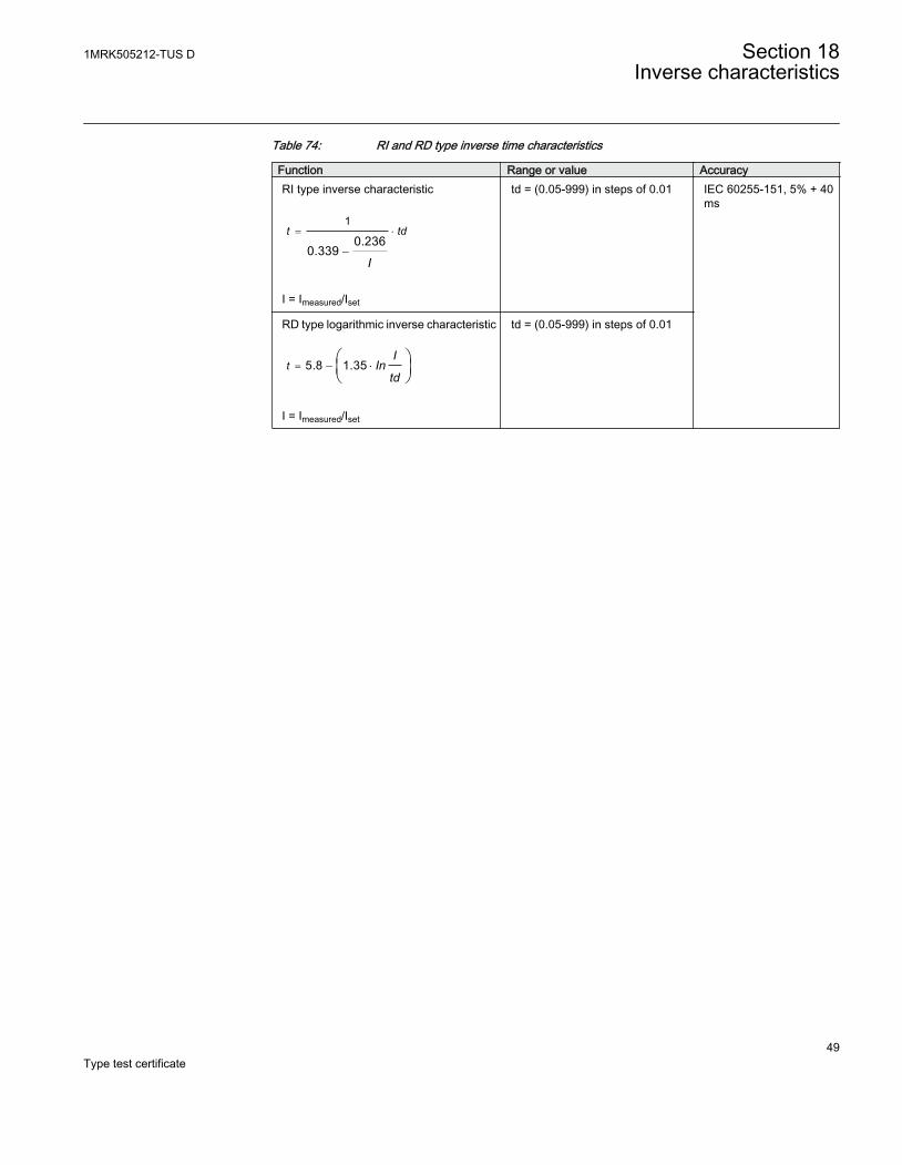
Table 74: RI and RD type inverse time characteristics
Function Range or value AccuracyRI type inverse characteristic
= ×
-
1
0.2360.339
t td
IEQUATION1656 V1 EN
I = Imeasured/Iset
td = (0.05-999) in steps of 0.01 IEC 60255-151, 5% + 40ms
RD type logarithmic inverse characteristic
= - ×æ öç ÷è ø
5.8 1.35tI
Intd
EQUATION1657 V1 EN
I = Imeasured/Iset
td = (0.05-999) in steps of 0.01
1MRK505212-TUS D Section 18Inverse characteristics
49Type test certificate
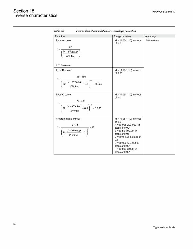
Table 75: Inverse time characteristics for overvoltage protection
Function Range or value AccuracyType A curve:
=-æ ö
ç ÷è ø
ttd
V VPickup
VPickupEQUATION1661 V1 EN
V = Vmeasured
td = (0.05-1.10) in stepsof 0.01
5% +40 ms
Type B curve:
=×
-× - -
æ öç ÷è ø
2.0
480
32 0.5 0.035
ttd
V VPickup
VPickupEQUATION1662 V1 EN
td = (0.05-1.10) in stepsof 0.01
Type C curve:
=×
-× - -
æ öç ÷è ø
3.0
480
32 0.5 0.035
ttd
V VPickup
VPickupEQUATION1663 V1 EN
td = (0.05-1.10) in stepsof 0.01
Programmable curve:
×= +
-× -
æ öç ÷è ø
P
td At D
V VPickupB C
VPickupEQUATION1664 V1 EN
td = (0.05-1.10) in stepsof 0.01A = (0.005-200.000) insteps of 0.001B = (0.50-100.00) insteps of 0.01C = (0.0-1.0) in steps of0.1D = (0.000-60.000) insteps of 0.001P = (0.000-3.000) insteps of 0.001
Section 18 1MRK505212-TUS DInverse characteristics
50Type test certificate
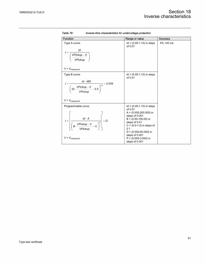
Table 76: Inverse time characteristics for undervoltage protection
Function Range or value AccuracyType A curve:
=-æ ö
ç ÷è ø
tdt
VPickup V
VPickupEQUATION1658 V1 EN
V = Vmeasured
td = (0.05-1.10) in stepsof 0.01
5% +40 ms
Type B curve:
×= +
-× -
æ öç ÷è ø
2.0
4800.055
32 0.5
tdt
VPickup V
VPickupEQUATION1659 V1 EN
V = Vmeasured
td = (0.05-1.10) in stepsof 0.01
Programmable curve:
×= +
-× -
é ùê úê úê úæ öê úç ÷ëè ø û
P
td At D
VPickup VB C
VPickupEQUATION1660 V1 EN
V = Vmeasured
td = (0.05-1.10) in stepsof 0.01A = (0.005-200.000) insteps of 0.001B = (0.50-100.00) insteps of 0.01C = (0.0-1.0) in steps of0.1D = (0.000-60.000) insteps of 0.001P = (0.000-3.000) insteps of 0.001
1MRK505212-TUS D Section 18Inverse characteristics
51Type test certificate
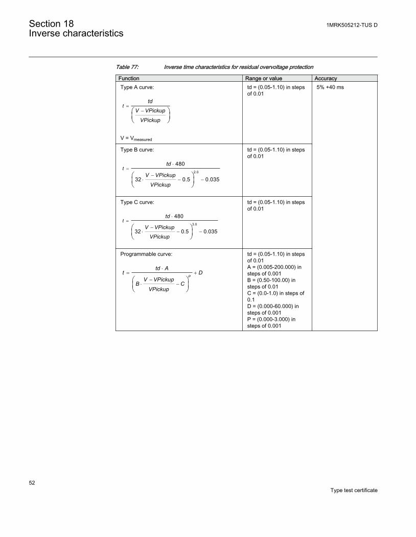
Table 77: Inverse time characteristics for residual overvoltage protection
Function Range or value AccuracyType A curve:
=-æ ö
ç ÷è ø
ttd
V VPickup
VPickupEQUATION1661 V1 EN
V = Vmeasured
td = (0.05-1.10) in stepsof 0.01
5% +40 ms
Type B curve:
=×
-× - -
æ öç ÷è ø
2.0
480
32 0.5 0.035
ttd
V VPickup
VPickupEQUATION1662 V1 EN
td = (0.05-1.10) in stepsof 0.01
Type C curve:
=×
-× - -
æ öç ÷è ø
3.0
480
32 0.5 0.035
ttd
V VPickup
VPickupEQUATION1663 V1 EN
td = (0.05-1.10) in stepsof 0.01
Programmable curve:
×= +
-× -
æ öç ÷è ø
P
td At D
V VPickupB C
VPickupEQUATION1664 V1 EN
td = (0.05-1.10) in stepsof 0.01A = (0.005-200.000) insteps of 0.001B = (0.50-100.00) insteps of 0.01C = (0.0-1.0) in steps of0.1D = (0.000-60.000) insteps of 0.001P = (0.000-3.000) insteps of 0.001
Section 18 1MRK505212-TUS DInverse characteristics
52Type test certificate

53
Contact us
ABB Inc.1021 Main Campus DriveRaleigh, NC 27606, USAPhone Toll Free: 1-800-HELP-365,menu option #8
ABB Inc.3450 Harvester RoadBurlington, ON L7N 3W5, CanadaPhone Toll Free: 1-800-HELP-365,menu option #8
ABB Mexico S.A. de C.V.Paseo de las Americas No. 31 LomasVerdes 3a secc.53125, Naucalpan, Estado De Mexico,MEXICOPhone (+1) 440-585-7804, menuoption #8
1MR
K50
5212
-TU
S D
© C
opyr
ight
201
2 A
BB
. All
right
s re
serv
ed.