type 444 din packed lever h4 closed bonnet conventional ... · packed lever h4 closed bonnet...
TRANSCRIPT

04/01LWN 482.01-E
Typ
e 44
4 D
IN
Type 444 DINPacked lever H4
Closed bonnetConventional design
Contents Chapter/Page
Flanged Safety Relief Valves – spring loaded
Materials • Conventional design 04/02
How to order
• Numbering system 04/04 • Article numbers 04/06
Dimensions and weights • Metric Units 04/07 • US Units 04/07
Pressure temperature ratings • Metric Units 04/08 • US Units 04/08
Flange drillings and facings 04/09 Order information – Spare parts 04/10 Available options 04/11 Approvals 04/12
Capacities • Steam [Metric Units + US Units] 04/13 • Air [Metric Units + US Units] 04/14 • Water [Metric Units + US Units] 04/15 Determination of coefficient 04/16 of discharge Kdr /αw
Type 444 DINType 444 DIN

How to order – Article numbers
04/06 LWN 482.01-E
Typ
e 44
4 D
IN
Type 444 DINType 444 DIN
Article numbers
DNI 25 25 50 65 80 80 DNo 50 80 80 100 100 100
Actual Orifi ce diameter d0 [mm] 23 37 46 60 74 74
Actual Orifi ce area A0 [mm2] 416 1075 1662 2827 4301 4301
Set pressure range S/G/L [barg]see page 04/08
0,1 – 6,8 6,81 – 16 Set pressure range S/G/L [psig] 1,5 – 98,6 98,61 – 232
Body material: 1.4404 (316L)Bonnet H2 Art.-No. 4444. 3642 3662 3672 3682 3692 3702closed H4 Art.-No. 4444. 3644 3664 3674 3684 3694 3704
Type 444Cap H2
Closed bonnetConventional design Type 444
Packed lever H4Closed bonnet
Conventional design

Conventional design
04/02 LWN 482.01-E
Typ
e 44
4 D
IN
Type 444 DINType 444 DIN
40 Cap H2
18 Adjusting screw
19 Lock nut
16 Upper spring plate
54 Spring
12 Spindle
9 Bonnet
14 Split ring
17 Lower spring plate
8 Guide with bushing
67 O-ring
60 O-ring
22 Lift stopper
61 Ball
7 Disc
5 Seat
1 Body
68 Clamp
57 Pin

Conventional design
04/03LWN 482.01-E
Typ
e 44
4 D
IN
Type 444 DINType 444 DIN
Please notice:
– Modifications reserved by LESER.– LESER can upgrade materials without notice.– Every part can be replaced by other material acc. to customer specification.
Materials
Item Component Type 4444 DIN
1 Body 1.4404 316L
5 Seat 1.4404 316L
7 Disc 1.4404 316L
8 Guide
1.4404 316L
with bushing PTFE +15% Glas
-"-
9 Bonnet 1.4404 316L
12 Spindle 1.4404 316L
14 Split ring 1.4404 316L
16 / 17 Spring plate 1.4404 316L
18Adjusting screw
with bushing 1.4404, PTFE + 15% Glas 316L, PTFE + 15% Glas
19 Lock nut 1.4404 316L
22 Lift stopper 1.4404 316L
40 Cap H2 1.4404 316L
54 Spring 1.4310
Stainless steel
57 Pin 1.4310
302
60 O-ring EPDM-FDA
-"-
61 Ball 1.4401
316
67 O-ring EPDM-FDA
-"-
68 Clamp 1.4401
316

Dimensions and weights
04/07LWN 482.01-E
Typ
e 44
4 D
IN
Type 444 DINType 444 DIN
Conventional design
Metric UnitsDNI 25 40 50 65 80 80
DNo 50 80 80 100 100 100
Actual Orifi ce diameter d0 [mm] 23 37 46 60 74 74
Actual Orifi ce area A0 [mm2] 416 1075 1662 2827 4301 4301
Set pressure range S/G/L [barg] see page 04/08 0,1 – 6,8 6,81 – 16
Weight [kg] 7 13 14 23 24 24
Center to face Inlet a 85 110 110 125 125 125[mm] Outlet b 90 128 128 160 160 160
Height (H4) [mm] Standard H max. 308 519 519 631 631 631
Body material: 1.4404 (316L) DIN Flange Inlet PN 16
Outlet PN 16
US UnitsDNI 25 40 50 65 80 80
DNo 50 80 80 100 100 100
Actual Orifi ce diameter d0 [inch] 0,91 1,46 1,81 2,36 2,91 2,91
Actual Orifi ce area A0 inch2] 0,644 1,667 2,576 4,383 6,666 6,666
Set pressure range S/G/L [psig] see page 04/08 1,5 – 98,6 98,61 – 232
Weight [Ibs] 16 29 31 51 53 53
Center to face Inlet a 33/8 45/16 45/16 415/16 415/16 415/16[inch] Outlet b 31/2 51/16 51/16 65/16 65/16 65/16
Height (H4) [inch] Standard H max. 121/8 207/16 207/16 2013/16 2013/16 2013/16
Body material: 1.4404 (316L) DIN Flange Inlet PN 16
Outlet PN 16

Pressure temperature ratings
04/08 LWN 482.01-E
Typ
e 44
4 D
IN
Type 444 DINType 444 DIN
Metric Units
DNI 25 40 50 65 80 80
DNO 50 80 80 100 100 100
Actual Orifi ce diameter d0 [mm] 23 37 46 60 74 74
Actual Orifi ce area A0 [mm2] 416 1075 1662 2827 4301 4301
Body material: 1.4404 (316L)
DIN Flange Inlet PN 16Outlet PN 16
Minimump [barg] S/G/L 0,1 0,1 0,1 0,1 0,1 6,81set pressure
Maximump [barg] S/G/L 16 16 16 16 6,8 16set pressure
Temperature min. [°C] -45acc. to DIN EN max. [°C] +200
Temperature min. [°C] -45acc. to ASME max. [°C] +200
US Units
DNI 25 40 50 65 80 80
DNO 50 80 80 100 100 100
Actual Orifi ce diameter d0 [inch] 0,91 1,46 1,81 2,36 2,91 2,91 Actual Orifi ce area A0 [inch2] 0,644 1,667 2,576 4,383 6,666 6,666
Body material: 1.4404 (316L)
DIN Flange Inlet PN 16Outlet PN 16
Minimump [psig] S/G/L 1,5 1,5 1,5 1,5 1,5 98,61set pressure
Maximump [psig] S/G/L 232 232 232 232 98,6 232set pressure
Temperature min. [°F] -49acc. to DIN EN max. [°F] +392
Temperature min. [°F] -49acc. to ASME max. [°F] +392

Flange drillings and facings
04/09LWN 482.01-E
Typ
e 44
4 D
IN
Type 444 DINType 444 DIN
Flange drillings DNI 25 40 50 65 80
DNO 50 80 80 100 100
Valve size 1" x 2" 11/2" x 3" 2" x 3" 21/2" x 4" 3" x 4"
Actual Orifi ce diameter d0 [mm] 23 37 46 60 74
Actual Orifi ce area A0 [mm2] 416 1075 1662 2827 4301
Body material: 1.4404 (316L)
Inlet
DIN EN 1092
PN 10 – – – – –
PN 16 * * * * * PN 25 – – – – –
PN 40 – – – – –
ASME B16.5 CL150
CL 300
Outlet
DIN EN 1092
PN 10 – – – – –
PN 16 * * * * * PN 25 – – – – –
PN 40 – – – – –
ASME B16.5 CL150
CL300
Please use Type 444 ANSI
Please use Type 444 ANSI
Flange facingsIndication Standard Inlet Outlet Remark
General
Flange undrilled – H38 H39
Lens seal form L(without sealing lens)
DIN 2696LWN 313.35
J11 J12
Acc. to DIN EN
Flange facing Inlet Outlet Remark
DIN EN 1092 (new) DIN 2526(old) PN 10 – PN 40 PN 10 – PN 40
Rz-data according to
DIN EN 1092 in µmsee also LWN 313.40)
Raised faceType B1
Type C
* * Facing: Rz = 12,5 – 50Type D
Type B2 Type E L36 L38 Facing: Rz = 3,2 – 12,5
Ste
el f
lang
es o
nlyTongue face C1) Tongue face F H94 H92
Groove face D1) Groove face N H93 H91
Male face E Male face V13 H96 H98
Female face F Female face R13 H97 H99
O-ring male face G Male face V14 J01 J02
O-ring female face H Female face R14 J03 J04
1) According to DIN EN 1092 groove depths and tongue heights increased compared to the formerly valid DIN (refer to LWN 313.40). LESER manufactures the groove at flanged valves by milling. If a customer demands a turned surface in the soil of the groove according to DIN 2512 and/or DIN EN 1092-1 an additional option code is necessary: “S01: bottom of the groove drilled”. Groove and tongue for PN160 flanges refer to DIN 2512/LWN 313.32.2) Smooth finish is not defined in the effective standards. For L ESER‘s definition for smooth finish see page 00/07.
For signs and symbols refer to page 00/07Note: Flange drillings and facings meet always the requirements of mentioned flange standards. Flange thickness and outer diameter may vary from flange standard.
Acc. to ASME B16.5
Please use Type 444 ANSI

04/12 LWN 482.01-E
Approvals
Typ
e 44
4 D
IN
Type 444 DINType 444 DIN
Approvals DNI 25 40 50 65 80 80
DNO 50 80 80 100 100 100
Actual Orifi ce diameter d0 [mm] 23 37 46 60 74 74
Actual Orifi ce area A0 [mm2] 416 1075 1662 2827 4301 4301
Set pressure range S/G/L [barg]see page 04/08
0,1 – 6,8 6,81 – 16
Set pressure range S/G/L [psig] 1,5 – 98,6 98,61 – 232
Europe Coefficient of discharge Kdr
DIN EN ISO 4126-1 Approval No. 072020111Z0008/0/08-2 S/G 0,7 0,55
L 0,48 0,48
Germany Coefficient of discharge αw
AD 2000-Merkblatt A2 Approval No. TÜV SV 576S/G 0,7 0,55
L 0,48 0,48
United States Coefficient of discharge KASME Sec. VIII Approval No. M37044 –
S/G 0,699 –Approval No. M37055 M37055
L 0,521 0,521
Canada Coefficient of discharge KCanada: CRN Approval No. OG1182.9C
S/G 0,699 –L 0,521 0,521
China Coefficient of discharge αw
CSBQTS Approval No.
S/G 0,7 0,55L 0,48 0,48
Russia Coefficient of discharge αw
GGTN/GOSGOTECHNADZORGOST R
Approval No. PPC 00-18458
S/G 0,7 0,55L 0,48 0,48
Classification societies
on request

04/13LWN 482.01-E
Typ
e 44
4 D
IN
Type 444 DINType 444 DIN Capacities – Steam
Capacities for saturated steam according to AD 2000-Merkblatt A2,based on set pressure plus 10 % overpressure.Capacities at 1 bar (14,5 psig) and below are based on 0,1 bar(1,45 psig) overpressure.
Metric Units AD 2000-Merkblatt A2 [kg/h]
DNI 25 40 50 65 80 80
DNO 50 80 80 100 100 100
Act. Orifice dia. d0 [mm] 23 37 46 60 74 74
Act. Orifice area A0 [mm2] 416 1075 1662 2827 4301 4301
LEOS/G*) [inch2] 0,462 1,195 1,847 3,142 4,779 4,779
Set pressure S/G [barg] 0,1–6,8 6,81–16
Set pressure [bar] Capacities [kg/h]
0,1 112 274 405 720 1093
0,2 144 353 524 927 1417
0,5 223 546 822 1434 2221
1 324 790 1209 2086 3262
2 529 1285 2002 3413 5377
3 699 1761 2770 4695 7237
4 872 2256 3487 5932 9023
5 1043 2700 4174 7101 10801
6 1215 3143 4858 8266 12573
7 1382 3575 5526 9402 11237
8 1552 4015 6206 10559 12619
9 1721 4455 6885 11714 14000
10 1891 4894 7564 12868 15380
12 2230 5772 8922 15179 18141
14 2562 6631 10249 17437 20840
16 2901 7507 11603 19740 23593
*) LEO S/G = LESER Effective Orifice steam/gas please refer to page 00/11How to use capacity-sheets refer to page 00/09
Capacities for saturated steam according to ASME Section VIII (UV),based on set pressure plus 10% overpressure.Capacities at 2,07 bar (30 psig) and below are based on 0,207 bar(3 psig) overpressure.
US Units ASME Section VIII [lb/h]
DNI 25 40 50 65 80 80
DNO 50 80 80 100 100 100
Act. Orifice dia. d0 [inch] 0,91 1,46 1,81 2,36 2,91 2,91
Act. Orifice area A0 [inch2] 0,644 1,667 2,576 4,383 6,666 6,666
LEOS/G*) [inch2] 0,462 1,195 1,847 3,142 4,779 4,779
Set pressure S/G [psig] 1,5–98,6 98,61–232
Set pressure [psig] Capacities [lb/h]
15 758 1962 3032 5159 7847
20 874 2262 3496 5948 9047
30 1106 2862 4423 7525 11447
40 1361 3522 5443 9261 14087
50 1616 4182 6463 10996 16726
60 1871 4842 7483 12732 19366
70 2126 5501 8503 14467 22006
80 2381 6161 9523 16202 24646
90 2636 6821 10543 17938 27285
100 2891 7481 11563 19673 29925
120 3401 8801 13604 23144 35205
140 3911 10121 15644 26615 40484
160 4421 11441 17684 30086 45764
180 4931 12761 19724 33557 51043
200 5441 14081 21764 37027 56323
220 5951 15401 23804 40498 61602
230 6206 16060 24824 42234 64242

04/14 LWN 482.01-E
Capacities – Air
Typ
e 44
4 D
IN
Type 444 DINType 444 DIN
Capacities for air according to AD 2000-Merkblatt A2, based on set pressure plus 10 % overpressure at 0 °C and 1013 mbar. Capacities at 1 bar (14,5 psig) and below are based on 0,1 bar (1,45 psig) overpressure.
Metric Units AD 2000-Merkblatt A2 [mn3/h]
DNI 25 40 50 65 80 80
DNO 50 80 80 100 100 100
Act. Orifice dia. d0 [mm] 23 37 46 60 74 74
Act. Orifice area A0 [mm2] 416 661 1075 1662 2827 6648
LEOS/G*) [inch2] 0,462 1,195 1,847 3,142 4,779 4,779
Set pressure S/G [barg] 0,1–6,8 6,81–16
Set pressure [bar] Capacities [mn3/h]
0,1 129 316 466 829 1257
0,2 167 409 607 1073 1640
0,5 262 640 964 1683 2607
1 386 941 1440 2484 3884
2 639 1551 2416 4119 6489
3 853 2150 3382 5732 8835
4 1071 2772 4284 7289 11088
5 1289 3335 5155 8771 13341
6 1506 3899 6026 10252 15594
7 1724 4462 6897 11733 14023
8 1942 5025 7767 13214 15793
9 2159 5588 8638 14696 17564
10 2377 6152 9509 16177 19334
12 2812 7278 11250 19140 22875
14 3248 8405 12991 22102 26416
16 3683 9532 14733 25065 29956
*) LEO S/G = LESER Effective Orifice steam/gas please refer to page 00/11How to use capacity-sheets refer to page 00/09
Capacities for air according to ASME Section VIII (UV),based on set pressure plus 10 % overpressure at 16 °C (60 °F).Capacities at 2,07 bar (30 psig) and below are based on 0,207 bar (3 psig) overpressure.
US Units ASME Section VIII [S.C.F.M.]
DNI 25 40 50 65 80 80
DNO 50 80 80 100 100 100
Act. Orifice dia. d0 [inch] 0,91 1,46 1,81 2,36 2,91 2,91
Act. Orifice area A0 [inch2] 0,644 1,667 2,576 4,383 6,666 6,666
LEOS/G*) [inch2] 0,462 1,195 1,847 3,142 4,779 4,779
Set pressure S/G [psig] 1,5–98,6 98,61–232
Set pressure [psig] Capacities [S.C.F.M.]
15 269 697 1077 1832 2786
20 310 803 1241 2112 3212
30 393 1016 1571 2672 4064
40 483 1250 1933 3288 5002
50 574 1485 2295 3904 5939
60 664 1719 2657 4521 6876
70 755 1953 3019 5137 7814
80 845 2188 3381 5753 8751
90 936 2422 3744 6369 9688
100 1026 2656 4106 6985 10625
120 1208 3125 4830 8218 12500
140 1389 3594 5555 9450 14375
160 1570 4062 6279 10682 16249
180 1751 4531 7003 11915 18124
200 1932 5000 7728 13147 19998
220 2113 5468 8452 14380 21873
230 2204 5703 8814 14996 22810

Capacities – Water
04/15LWN 482.01-E
Typ
e 44
4 D
IN
Type 444 DINType 444 DIN
Capacities for water according to AD 2000-Merkblatt A2, based on set pressure plus 10 % overpressure at 20 °C (68 °F).Capacities at 1 bar (14,5 psig) and below are based on 0,1 bar (1,45 psig) overpressure.
Metric Units AD 2000-Merkblatt A2 [103kg/h]
DNI 25 40 50 65 80 80
DNO 50 80 80 100 100 100
Act. Orifice dia. d0 [mm] 23 37 46 60 74 74
Act. Orifice area A0 [mm2] 416 1075 1662 2827 4301 4301
LEOL*) [inch2] 0,516 1,336 2,065 3,513 5,343 5,343
Set pressure L [barg] 0,1–6,8 6,81–16
Set pressure [bar] Capacities [103kg/h]
0,1 4,54 11,8 18,2 30,9 47
0,2 5,56 14,4 22,2 37,8 57,6
0,5 7,87 20,4 31,5 53,5 81,4
1 10,6 27,6 42,6 72,5 110
2 15,1 39 60,2 102 156
3 18,4 47,7 73,8 126 191
4 21,3 55,1 85,2 145 220
5 23,8 61,6 95,3 162 246
6 26,1 67,5 104 178 270
7 28,2 72,9 113 192 292
8 30,1 77,9 120 205 312
9 31,9 82,7 128 217 331
10 33,7 87,2 135 229 349
12 36,9 95,5 148 251 382
14 39,8 103 159 271 412
16 42,6 110 170 290 441
*) LEO L = LESER Effective Orifice liquids please refer to page 00/12How to use capacity-sheets refer to page 00/09
Capacities for water according to ASME Section VIII (UV), based on set pressure plus 10 % overpressure at 21 °C (70 °F).Capacities at 2,07 bar (30 psig) and below are based on 0,207 bar (3 psig) overpressure.
US Units ASME Section VIII [US-G.P.M.]
DNI 25 40 50 65 80 80
DNO 50 80 80 100 100 100
Act. Orifice dia. d0 [inch] 0,91 1,46 1,81 2,36 2,91 2,91
Act. Orifice area A0 [inch2] 0,644 1,667 2,576 4,383 6,666 6,666
LEOL*) [inch2] 0,516 1,336 2,065 3,513 5,343 5,343
Set pressure L [psig] 1,5–98,6 98,61–232
Set pressure [psig] Capacities [US-G.P.M.]
15 54,1 140 216 368 560
20 61,1 158 245 416 633
30 73,2 190 293 498 758
40 84,6 219 338 576 875
50 94,6 245 378 643 979
60 104 268 414 705 1072
70 112 290 447 761 1158
80 120 310 478 814 1238
90 127 328 507 863 1313
100 134 346 535 910 1384
120 146 379 586 997 1516
140 158 409 633 1077 1638
160 169 438 677 1151 1751
180 179 464 718 1221 1857
200 189 489 756 1287 1958
220 198 513 793 1350 2053
230 203 525 811 1380 2099

04/11LWN 482.01-E
Typ
e 44
4 D
IN
Type 444 DINType 444 DIN Available Options
Packed lever H4 H4
Lift indicator bonnet J38: Adaptor bonnet DN 25 J93: Lift indicator
Lift indicator H4 DN 40 to DN 80 J38: Adaptor H4 J93: Lift indicator
Screwed cap H2
For further information refer to“Accesoires and Options”, page 99/01
99/04 LWN 482.01-E
Op
tio
ns
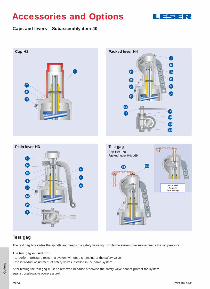
Caps and levers – Subassembly item 40
Accessories and OptionsAccessories and Options
Cap H2
2
23
24
25
Packed lever H4
1
12
1.5
13
3a
1.6
14
25
23
1.8
1.7
24
1.10
1.11
1.9
1.4
23
4
Plain lever H3
12
Test gag Cap H2: J70
Packed lever H4: J69
14
13
1
BLOCKEDRemove
after testing
93 93.5
6
3b
22
24
10
Test gag
The test gag blockades the spindle and keeps the safety valve tight while the system pressure exceeds the set pressure.
The test gag is used for: - to perform pressure tests in a system without dismantling of the safety valve- the individual adjustment of safety valves installed in the same system
After testing the test gag must be removed because otherwise the safety valve cannot protect the system against unallowable overpressure!