type 05 pneumatic actuator used with globe valves · type 05 pneumatic actuator used with globe...
TRANSCRIPT


Nor’ East
Type 05 Pneumatic Actuator Used With Globe Valves
D-Type05P © 2009 DeZURIK
Instructions
These instructions are intended for personnel who are responsible for installation, operation and maintenance of your DeZURIK Actuator.
Safety
Messages
All safety messages in the instructions are flagged with the word Caution, Warning or Danger. These messages must be followed exactly to avoid equipment damage, personal injury or death.
Safety label(s) on the product indicate hazards that can cause equipment damage, personal injury or death. If a safety label becomes difficult to see or read, or if a label has been removed, please contact DeZURIK for replacement label(s).
Personnel involved in the installation or maintenance of valves should be constantly alert to potential emission of pipeline material and take appropriate safety precautions. Always wear suitable protection when dealing with hazardous pipeline materials. Handle valves, which have been removed from service with suitable protection for any potential pipeline material in the valve.
Inspection Your DeZURIK Actuator has been packaged to provide protection during shipment. Carefully inspect the unit for damage upon arrival and file a claim with the carrier if damage is apparent.
Parts Order parts from your local sales representative, or directly from DeZURIK, as listed on the back cover. Recommended spare parts are listed on the assembly drawing. These parts should be stocked to minimize downtime.
DeZURIK
Service
DeZURIK service personnel are available to install, maintain and repair all DeZURIK products. DeZURIK also offers customized training programs and consultation services.
For more information, contact your local DeZURIK sales representative or visit our website at www.dezurik.com.

Nor’ East
Type 05 Pneumatic Actuator Used With Globe Valves
December 2010 Page 1 D-Type05P
Table of
Contents
Description
Action - - - - - - - - - - - - - - - - - - - - - - - - - - - - - - - - - - - - - - - -
Pressure and Travel - - - - - - - - - - - - - - - - - - - - - - - - - - - - - -
2
2
Maximum Allowable Air Pressure - - - - - - - - - - - - - - - - - - - - - - 3
Installation
Air Connections - - - - - - - - - - - - - - - - - - - - - - - - - - - - - - - - -
4
Parts Identification
Name Plate - - - - - - - - - - - - - - - - - - - - - - - - - - - - - - - - - - - -
4
Actuator Removal - - - - - - - - - - - - - - - - - - - - - - - - - - - - - - - - - 6
Diaphragm Replacement
Air-to-Close (Direct Acting) Actuator - - - - - - - - - - - - - - - - - - -
Air-to-Open (Reverse Acting) Actuator - - - - - - - - - - - - - - - - -
7
8
Mounting Actuator
Single and Double Seated Valves - - - - - - - - - - - - - - - - - - - -
Three-Way Valves - - - - - - - - - - - - - - - - - - - - - - - - - - - - - - -
9
10
Stem Adjustment
Air-to-Close (Direct Acting) Actuator and Valve - - - - - - - - - - -
Air-to-Open (Reverse Acting) Actuator and (Reverse Acting) Valve - - - - - - - - - - - - - - - - - - - - - - - - - - - - - - - - - - - - - - - - -
Air-to-Open (Reverse Acting) Actuator and (Direct Acting) Valve - - - - - - - - - - - - - - - - - - - - - - - - - - - - - - - - - - - - - - - - -
12
12
12
Spring Adjustment
Air-to-Close (Direct Acting) Actuator - - - - - - - - - - - - - - - - - - -
Air-to-Open (Reverse Acting) Actuator - - - - - - - - - - - - - - - - -
Three-Way Valves - - - - - - - - - - - - - - - - - - - - - - - - - - - - - - -
13
13
14
Troubleshooting - - - - - - - - - - - - - - - - - - - - - - - - - - - - - - - - - - - 14

Nor’ East
Type 05 Pneumatic Actuator Used With Globe Valves
D-Type05P Page 2 December 2010
Description The Type 05 Actuator is a long stroke, pneumatic diaphragm actuator with deep drawn aluminum case plates and rolling type diaphragm which provides increased sensitivity and maintains constant area throughout a full 1-1/2” stroke.
Action With Type 05 Actuators, two actions, direct and reverse provide the necessary valve operating force in either of two directions. When air is applied to the diaphragm, a direct acting actuator will push down - while a reverse actuator will push up. See Figure 1.
Figure 1 – Direct and Reverse Action
Pressure and Travel
Table A: Actuator Thrust (lbs)
Spring Range, psig 3-15 3-9 9-15 5-13 6-30 7-18
Stud Dia (Inches)
Actuator Action
Actuator Travel
Air Supply
psig Thrust (lbs)
1-3/8 or 1-7/8
Direct At Full Travel
18 120 360 120 300 - -
25 400 640 400 480 - 280
35 800 1040 800 880 200 680
Reverse At Zero Travel
0 115 115 340 190 - 250
2-1/4
Direct At Full Travel
18 120 360 120 200 - -
25 400 640 400 480 - 280
35 800 1040 800 880 200 680
50 1400 1640 1400 1480 800 1280
Reverse At Zero Travel
0 115 115 340 190 230 250
Table B: Available Spring Ranges
Spring Range psig
Actuator Travel (Inches)
1/4” 9/16” 3/4” 1” 1-1/8” 1-1/4” 1-1/2”
3-15 X X X X X X X
3-9 - X X - - - -
9-15 - X X - - - -
5-13 - - - - - - X
6-30 - - - - - X -
7-18 - - - - - - X
Nor’ East
Type 05 Pneumatic Actuator Used With Globe Valves
December 2010 Page 3 D-Type05P
Maximum
Allowable
Air
Pressure
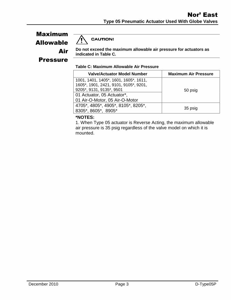
Do not exceed the maximum allowable air pressure for actuators as indicated in Table C.
Table C: Maximum Allowable Air Pressure
Valve/Actuator Model Number Maximum Air Pressure
1001, 1401, 1405*, 1601, 1605*, 1611, 1605*, 1901, 2421, 9101, 9105*, 9201, 9205*, 9131, 9135*, 9501 50 psig 01 Actuator, 05 Actuator*, 01 Air-O-Motor, 05 Air-O-Motor
4705*, 4805*, 4905*, 8105*, 8205*, 8305*, 8605*, 8905*
35 psig
*NOTES: 1. When Type 05 actuator is Reverse Acting, the maximum allowable air pressure is 35 psig regardless of the valve model on which it is mounted.

Nor’ East
Type 05 Pneumatic Actuator Used With Globe Valves
D-Type05P Page 4 December 2010
Installation
If valve is used in a water system, the water must be adequately treated to prevent the formation of rust, carbonates and other undesirable deposits on valve parts. Otherwise, deposit buildups can damage packing, seats or other internal valve parts.
For maximum efficiency and minimum wear, install valve in the vertical position with valve stem pointing up.
Be sure to leave a minimum of 4 inches clearance for actuator removal.
Before installing, be sure valve and pipeline are clean inside and free of scale, chips and welding spatter.
The valve must be installed with the fluid flow in the direction of the arrow on the valve body (pressure under plug). Pipes must be lined squarely with the valve at each connection. If they are forced into the valve, the body may become twisted, causing improper seating. Be sure there are no pockets in the line where condensate could accumulate and cause an undesirable water hammer.
Be sure that the flow medium and ambient temperature and the selected location will not exceed the maximum temperature limitations for the valve or actuator.
All air connections are 1/4-inch NPT. Corresponding size tubing and fittings are recommended for the rest of the lines.
Air Connections NOTE: Air supply must be filtered and should never exceed 345 kPa (50 psi). A minimum constant air pressure will increase diaphragm life.
Connect diaphragm case (“INSTRUMENT” Connection if positioner is used) to controller with 1/4-inch copper tubing.
Install air pressure regulator in supply line, when positioner is used, to maintain steady air pressure and protect the diaphragm.
With springless type actuators, connect supply line to air pressure regulator and gage (which should be piped to constant loading side of diaphragm).
Check all air Connections for leaks.
Parts
Identification
Nameplate Data
The nameplate gives vital information on valve construction and operation. Always reference the serial number when ordering spare parts.
The spring range (on spring diaphragm actuators) is factory set to specifications on the order. Note the type of trim material, packing and lubricant number (“NONE” means packing does not require lubrication.) Remember that a change in operating conditions may mean a change in trim material, packing and lubricant type. Keep a permanent record of all nameplate information.

Nor’ East
Type 05 Pneumatic Actuator Used With Globe Valves
December 2010 Page 5 D-Type05P
Parts Identification
(Continued)
Figure 2 – Typical Air-to-Close (Direct Acting) Actuator Assembly
Figure 3 – Typical Air-to-Open (Reverse Acting) Actuator Assembly
Nor’ East
Type 05 Pneumatic Actuator Used With Globe Valves
D-Type05P Page 6 December 2010
Actuator
Removal
Stop pipeline flow and completely release pipe line pressure.
This valve is a pressure vessel. The bonnet will blow off the actuator if the bonnet bolts are removed with pressure in the valve. Completely release pressure before disassembling the valve.
Disconnect and lock out the pneumatic or electrical power to prevent accidental operation of the actuator.
Moving parts from accidental operation of power actuator can cause personal injury or equipment damage. Disconnect and lock out power to actuator before removal.
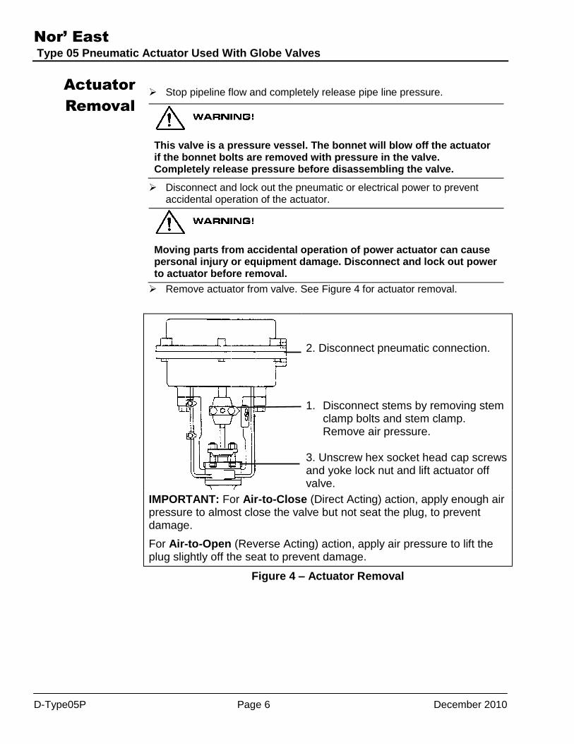
Remove actuator from valve. See Figure 4 for actuator removal.
2. Disconnect pneumatic connection.
1. Disconnect stems by removing stem
clamp bolts and stem clamp. Remove air pressure.
3. Unscrew hex socket head cap screws and yoke lock nut and lift actuator off valve.
IMPORTANT: For Air-to-Close (Direct Acting) action, apply enough air pressure to almost close the valve but not seat the plug, to prevent damage.
For Air-to-Open (Reverse Acting) action, apply air pressure to lift the plug slightly off the seat to prevent damage.
Figure 4 – Actuator Removal
Nor’ East
Type 05 Pneumatic Actuator Used With Globe Valves
December 2010 Page 7 D-Type05P
Diaphragm
Replacement
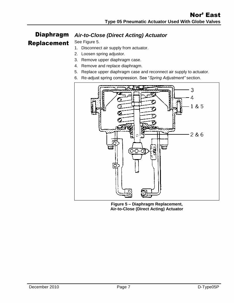
Air-to-Close (Direct Acting) Actuator See Figure 5.
1. Disconnect air supply from actuator.
2. Loosen spring adjustor.
3. Remove upper diaphragm case.
4. Remove and replace diaphragm.
5. Replace upper diaphragm case and reconnect air supply to actuator.
6. Re-adjust spring compression. See “Spring Adjustment” section.
Figure 5 – Diaphragm Replacement, Air-to-Close (Direct Acting) Actuator

Nor’ East
Type 05 Pneumatic Actuator Used With Globe Valves
D-Type05P Page 8 December 2010
Diaphragm Replacement
(Continued)
Air-to-Open (Reverse Acting) Actuator See Figure 6.
1. Disconnect air supply from actuator.
2. Loosen spring adjustor to relieve spring compression.
3. Remove stem clamp and disconnect actuator and valve stems.
4. Remove upper diaphragm case, spring flange (when provided) and spring.
5. Lift diaphragm plate, diaphragm and actuator stem out of lower case.
6. Remove the three diaphragm retainer screws and pull out the diaphragm retainer.
7. Place new diaphragm in lower diaphragm case so the center cylindrical section is up.
8. Pull center cylindrical section completely through hole in lower diaphragm case.
9. Wet the diaphragm retainer and insert it approximately 1/4 inch into the cylindrical section of the diaphragm.
10. Push diaphragm retainer up until flush with lower diaphragm case, making certain the beat is seated in the external groove on the diaphragm plate and a convolution is formed around the retainer on the inside. Secure with three diaphragm retainer screws.
11. Replace the diaphragm plate and actuator stem.
12. Replace spring and spring flange (when provided).
13. Replace upper case and secure with case bolts.
14. Connect actuator and valve stems. See Mounting Actuator section.
15. Reconnect air supply to actuator.
16. Re-adjust spring compression. See Spring Adjustment section.
Figure 6 – Diaphragm Replacement, Air-to-Open (Reverse Acting) Actuator

Nor’ East
Type 05 Pneumatic Actuator Used With Globe Valves
December 2010 Page 9 D-Type05P
Mounting
Actuator
Normally the valve and actuator are factory assembled and adjusted before shipment. If the actuator needs to be field mounted, use the following procedures for Reverse or Directing Acting actuator and valve combination.
Single and Double Seated Valves Air-to-Close Action (Direct Acting) Actuator and Valve
Stem Clamp Design
1. Mount actuator onto bonnet and lock in place.
2. With no air pressure on actuator, seat valve plug, raise stem and plug a distance equal to the travel specified on nameplate.
3. Lock valve stem to actuator stem with stem clamp.
Stem Head Design
1. Screw lock nut onto actuator stem.
2. Place stem connector onto stem head.
3. Mount actuator onto bonnet and lock in place.
4. Inset travel indicator, and raise valve stem to contact actuator stern.
5. Screw stem connector onto actuator stern until stem head is tight against actuator stem.
6. Hold stem connector with wrench, and tighten lock nut against travel indicator and stem connector.
Air-to-Open Action (Direct Acting) Actuator and (Reverse Acting) Valve
Stem Clamp Design
1. Mount actuator onto bonnet and lock in place.
2. Apply sufficient air pressure to actuator to lower actuator stem 1/16 inch.
3. Pull up valve stem and seat the plug. Lock valve stem to actuator stem with stem clamp.
Stem Head Design
1. Screw lock nut onto actuator stem.
2. Place stem connector onto stem head.
3. Mount actuator onto bonnet and lock in place.
4. Insert travel indicator and pull valve stem up to seat plug.
5. Apply sufficient air pressure to lower actuator stem; screw stem connector onto actuator stem until stem head is tight against actuator stem.
6. Tighten lock nut against travel indicator and stem connector.

Nor’ East
Type 05 Pneumatic Actuator Used With Globe Valves
D-Type05P Page 10 December 2010
Mounting Actuator
(Continued)
Air-to-Open (Reverse Acting) Actuator and (Direct Acting) Valve
Stem Clamp Design
1. Push valve stem down and seat the plug.
2. Mount actuator onto bonnet and lock in place.
3. Apply sufficient air pressure to actuator to raise actuator stem 1/16 inch.
4. Lock valve stem to actuator stem with stem clamp.
Stem Head Design
1. Push valve stem down, and seat the plug.
2. Screw lock nut onto actuator stem.
3. Place stem connector onto stem head.
4. Mount actuator onto bonnet.
5. Insert travel indicator and screw stern connector onto actuator stem until stem head is tight against actuator stem.
NOTE: Be sure there is clearance between bottom of yoke and top of bonnet.
6. Tighten lock nut against travel indicator and stem connector.
7. Apply air pressure to raise stern and permit actuator to seat on bonnet.
8. Lock actuator in place.
Three-Way Valves Air-to-Close Action (Direct Acting) Actuator
Stem Clamp Design
1. Mount actuator onto bonnet and lock in place.
2. Apply sufficient air pressure to actuator to lower actuator stem 1/16 inch.
3. Pull valve stem up until valve plug seats.
4. Lock valve stem to actuator stem with stem clamp.
5. Reposition travel indicator scale if necessary.
Stem Head Design
1. Screw lock nut onto actuator stem.
2. Place stem connector onto stem head.
3. Mount actuator onto bonnet and lock in place.
4. Inset travel indicator, and raise valve stem to contact actuator stern.
5. Screw stem connector onto actuator stern until stem head is tight against actuator stem.
6. Hold stem connector with wrench, and tighten lock nut against travel indicator and stem connector.

Nor’ East
Type 05 Pneumatic Actuator Used With Globe Valves
December 2010 Page 11 D-Type05P
Mounting Actuator
(Continued)
Air-to-Open (Reverse Acting) Actuator
Stem Clamp Design
1. Push valve stem down until valve plug seats.
2. Mount actuator onto bonnet and lock in place.
3. Apply sufficient air pressure to actuator to raise actuator stem 1/16 inch.
4. Lock valve stem to actuator stem with stem clamp.
5. Reposition travel indicator scale if necessary.
Stem Head Design
1. Push valve stem down, and seat the plug.
2. Screw lock nut onto actuator stem.
3. Place stem connector onto stem head.
4. Mount actuator onto bonnet.
5. Insert travel indicator and screw stern connector onto actuator stem until stem head is tight against actuator stem.
NOTE: Be sure there is clearance between bottom of yoke and top of bonnet.
6. Tighten lock nut against travel indicator and stem connector.
7. Apply air pressure to raise stern and permit actuator to seat on bonnet.
8. Lock actuator in place.

Nor’ East
Type 05 Pneumatic Actuator Used With Globe Valves
D-Type05P Page 12 December 2010
Stem
Adjustment
Air-to-Close (Direct Acting) Actuator and Valve 1. With no air pressure in actuator, seat valve plug. Raise stem and plug a
distance equal to the travel specified on the nameplate.
2. Lock valve stem to actuator stem with stem clamp.
Note: lf necessary, loosen travel indicator scale screws and align scale to travel indicator set at “0”. See Figure 7.
Air-to-Open (Reverse Acting) Actuator and (Reverse Acting) Valve 1. Apply sufficient air pressure to actuator to lower actuator stem 1/16 inch.
2. Pull up valve stem and seat the plug. Lock valve stem to actuator stem with stem clamp.
Air-to-Open (Reverse Acting) Actuator and (Direct Acting) Valve 1. Apply sufficient air pressure to actuator to raise actuator stem 1/16 inch.
2. Lock valve stem to actuator stem with stem clamp.
Note: If necessary, loosen travel indicator scale screws and align scale to travel indicator set at “S”. See Figure 7.
Figure 7 – Travel Indicator and Scale Alignment

Nor’ East
Type 05 Pneumatic Actuator Used With Globe Valves
December 2010 Page 13 D-Type05P
Spring
Adjustment
Factory adjustment provides for a complete actuator stroke for a pressure change from 21 to 103 kPa (3 to 15 psi) or 41 to 207 kPa (6 to 30 psi) with heavier spring. The operating spring can be shifted up or down if necessary. The starting point, with no external load, should not be adjusted more than 34 kPa (5 psi), for a 21 to 103 kPa (3 to 15 psi) spring, or 69 kPa (10 psi), for a 41 to 207 kPa (6 to 30 psi) spring. Adjustment of less than 1 psi is not recommended.
Air-to-Close (Direct Acting) Actuator 1. Using a 0-60 psig air regulator and gage, gradually apply initial air
pressure to the actuator, (3 psig for 3-15 psig spring, 6 psig for 6-30 psig spring, etc.). Actuator stem will either move down or remain stationary.
2. If the actuator stem moves down, screw the spring adjustor into the lower case until stem starts to move up.
3. Keep turning adjustor until stem stops.
4. If stem remains stationary, unscrew spring adjustor until stem starts to move down.
5. Screw spring adjustor in, moving stem up until stem stops moving.
6. Gradually increase air pressure to maximum psig (15 psig for 3-15 psig spring, 30 psig for 6-30 psig spring, etc.). If actuator stem stops before reaching maximum psig, spring adjustor was not screwed up far enough on initial spring adjustment.
7. Adjust air regulator back to initial psig, and screw spring adjustor into lower case.
8. Reapply maximum psig. If stem stops at maximum psig, apply one more psig air to actuator.
NOTE: If actuator stem moves down, adjustor was screwed up too far on initial adjustment or there is too much overtravel; check stem adjustment. (See Stem Adjustment section for adjusting stem.)
9. Reset initial psig, unscrewing adjustor.
10. When stem stops at maximum psig (not before or after), this adjustment is complete.
Air-to-Open (Reverse Acting) Actuator 1. Using a 0-60 psig air regulator and gage, apply initial psig air pressure to
actuator actuator (3 psig for 3-15 psig spring, 6 psig for 6-30 psig spring, etc.). Actuator will either move up or remain stationary.
2. If the actuator stem moves up, turn the spring adjustor into the housing until the stem starts to move down.
3. Continue turning adjustor until stem stops.
4. If the actuator remains stationary, unscrew the spring adjustor until stem starts to move up.
5. Turn spring adjustor into upper case, moving stem down until stem stops moving.
Nor’ East
Type 05 Pneumatic Actuator Used With Globe Valves
D-Type05P Page 14 December 2010
Spring Adjustment
(Continued)
Three-Way Valves Direct Acting Actuator
1. Gradually increase air pressure to maximum psig (15 psig for 3-15 psig spring, 30 psig for 6-30 psig spring, etc.).
2. If actuator stem stops before valve travel is completed, spring adjustor was screwed in too far on initial spring adjustment. Adjust air regulator back to initial psig and turn spring adjustor out of yoke.
3. If valve travel s completed before maximum psig is applied, spring adjustor was not screwed in far enough on initial spring adjustment. Reset initial psig, screwing in adjustor.
Reverse Acting Actuator
1. Using a 0-60 psig air regulator and gage, apply initial air pressure to actuator (3 psig for 3-15 psig spring, 6 psig for 6-30 psig spring, etc.). Actuator stem will move up or remain stationary.
2. If the actuator stem moves up, turn spring adjustor into upper case until stem just starts to move down.
3. If the actuator stem remains stationary, unscrew spring adjustor until stem just starts to move up.
Trouble-
Shooting
If the actuator does not function properly, check the following points while the actuator is still in service.
1. Are air connections tight?
2. Are diaphragm case bolts tight?
3. Is actuator firmly fastened to yoke or base plate?

Nor’ East
Type 05 Pneumatic Actuator Used With Globe Valves
D-Type05P Page 15 December 2010
Guarantee
Products, auxiliaries and parts thereof, of Nor’East Controls’ manufacture, are guaranteed for a period of one year from the date of shipment against
defective workmanship and material only, when properly installed, operated and serviced in accordance with Nor’East Controls’ recommendations.
Replacement for items of Nor’East Controls’ manufacture will be made free of charge if proved to be defective within such time. No claim for special or consequential damages, transportation, or labor shall be allowed. Purchaser shall be solely responsible for determining suitability for use and in no event
shall Nor’East Controls be liable in this respect. Equipment or parts manufactured by others but furnished by Nor’East Controls will be repaired or replaced,
only to the extent provided in the original manufacturer’s warranty to Nor’East Controls. Nor’East Controls does not guarantee resistance to corrosion, erosion, abrasion or other sources of failure, nor does Nor’East Controls guarantee a minimum length of service. Failure of the purchaser to give prompt
written notice of any alleged defect under this guarantee forthwith upon its discovery, or use and possession thereof after an attempt has been made and
completed by someone other than Nor’East Controls or an authorized representative to remedy defects therein, or failure to return products or parts for replacement as herein provided, of failure to install, operate, and maintain said products or parts according to instructions provided by Nor’East Controls, of
failure to pay the entire contract price when due, shall be a waiver of all rights under these representations.
The foregoing guarantee shall be null and void, if, after shipment from our factory, the item is modified in any way or component of another manufacturer,
such as but not limited to; an actuator is attached to the item by valves & controls other than a Nor’East Controls
Factory Service Personnel. All orders accepted shall be deemed accepted subject to this guarantee, which shall be exclusive of any other previous guarantee,
and this shall be the only effective guarantee or warranty binding on Nor’East Controls, anything to the contrary contained in the purchase order, or
represented by any agent or employee of Nor’East Controls, in writing or otherwise, notwithstanding, including but not limited to implied warranties.
THE FOREGOING OBLIGATIONS ARE IN LIEU OF ALL OTHER OBLIGATIONS AND LIABILITIES INCLUDING
WARRANTIES OF FITNESS OR MERCHANTABILITY OR OTHERWISE, EXPRESSED OR IMPLIED IN FACT OR BY LAW,
AND STATE NOR’EAST CONTROLS AND EXCLUSIVE LIABILITY AND PURCHASER’S EXCLUSIVE REMEDY FOR ANY
CLAIM IN CONNECTION WITH THIS SALE OR FURNISHING OF SERVICES, GOODS, OR PARTS, THEIR OWN DESIGN,
SUITABILITY FOR USE, INSTALLATION OR OPERATION.
Limitation of Liability
In no event shall Nor’East Controls be liable for any direct, indirect, special or consequential damages whatsoever, and
Nor’East Controls’ liability, under no circumstances, will exceed the contract price for the goods and/or services for which
liability is claimed. Any action for breach of contract must be commenced within 1 year after the cause of the action has
occurred.
1000 Riverside Street, Portland, Maine 04103 Ph: 207-210-6633 Fax: 207-210-6634
Sales and Service
Nor’ East Controls representatives are located in major cities throughout the world.
For the name of the representative nearest you, contact:
Web site:www.allagashinternational.com E-Mail:[email protected]
Nor’ East reserves the right to incorporate our latest design and material changes without notice or
obligation. Design features, materials of construction and dimensional data, as described in this bulletin,
are provided for your information only and should not be relied upon unless confirmed in writing by
Nor’ East Controls. Certified drawings are available upon request.