turbomachines
DESCRIPTION
turbomachinesTRANSCRIPT

ROTOR DESIGN AND VIBRATION RESPONSE by
F. L. Weaver Manager of Engineering
De Laval Turbine, Inc. Trenton, New Jersey
Mr. Weaver holds the posztwn of Manager of Engineering, Turbine Division, DELAV AL Turbine Inc., Trenton, N. /. In this position he is responsible for the direction of all Product Engineering and all Design activities for this organization.
He holds Professional En[!ineers License for both the State of :lfassa· chusetts and the State of l\'eu· Jersey. He is active in technical societies
and is a member of The Society of .l/echanical En{!ineers. Society of 1\'az·al Engineers, and the Society of .\'anti Architects and Marine Engineers.
His undergraduate 1eork u·as taken at Roanoke College where he receil·ed a R.S. Degree majoring in .1/athematics. He subsequently attended the .llassachuse/ls Institute of Technology and obtained Bachelor of Science and a Master of Science Degree in Electrical Engineering.
Mr. Weaver R'as associated tdth the General Electric Company during the period from 19.17 through 1%7, and held various positions of Engineering responsibility in the Medium Steam Turbine and Small Steam Turbine Departments of that Company, and teas Mana{!er for Industrial, Nary and Marine Turbine En[!ineering for this latter Department until joining DELAVAL in Sep· tember 1967.
He is married, and has a son and daughter, both of which are married, U'ith one grandson and one granddaughter.
ABSTRACT
A study is presented of a simple shaft confip:uration. This studv shows the relath·e effect of variables of weight distri
.lmtion and support stiffness on the re
sponse of the rotor. In particular. these \·ariahles are related to alternating load at the bearings due to an unbalance in the rotor. Comparisons are drawn between the study results and construction details in order that qualitative judgments may be made.
INTRODUCTION
The smoothness of operation of a rotor is of interest to all people concerned with the design, purchase or use of the rotor. The values of critical speeds, or the speed ranges in which critical speeds are prohibited are commonly specified in machinery purchase orders. It is the purpose of this paper to present performance data on a simple shaft which will lead to better fundamental understanding of the various factors affecting rotor performance and their relative value or influence.
142
MID SPA� WEIGHT
Figure 1 illustrates the effect of 11ei�ht di!'tribution in the mid span of the rotor. All critical speed \·alues are for a 12" long ln 6" diameter !'haft on 1en stiff supports ha\'inp: a
L sp
.rinp: :,rrad ient of 10!' pounds per
inch. The results for the uniform shaft. Fip:ure 1-a. p:i1·es a value of the ratio of serond to first critical of -LO. This is the true 1·alue of this ratio for anv size uniform shaft on ri�id supports. Howe\·er. it ca� be radicalh· different for various \Ieight distributions within the
· rotor span.
'
A sinp:le wheel located at the shaft mid span. Fi:,rure 1-h. will ha\'e maximum effed in lowerin:,r the first critical speed. hut 11 ill ha1·e n�inimal effect on the second critical speed since the 11llt'el i" locilted at the �haft node for the second criticaL Tl�e ratio of "econd to first critical is S.62. for the 21:0 pound 11 ei�ht 11 hid1 ha>' hef'n used in this example. The chan�e in "P�"ed ratio from LO to 5.62 is due to reduction in fir>'! critical alone since
there 11as no chan�e in second critical. This simple case assumed a dimensionless point 11 ei:,rht for the wheel at mid span. It is apparent from this example that by changing the amount of 11eip:ht at center span it is theoretically possible to make the ratios of second to first critical any desired value greater than LO.
Two equal weip:hts placed at one-third span, Fi:,rure 1-c, ha\·e approximately the same effect on hoth first and second criticals !'O that the ratio of second to first critical remains approximately constant at -LO regardle!'s of the amount of 11eight which is placed equally at these two locations.
The last example. Figure 1-d, illustrates the effect of locating equal weights at one quarter span. This is
MID SPAN WEIGHT 1-o----72' --------1 6' dia. r-------------�_i AJi Jr-.
280 lbs. j--36 =±=36 .__, BJT k
140 lbs. 140 lbs. r-24 t24 :t24 -j CJT Tb 140 lbs. 140 lbs.
412t=48 ==112-r-o,t J,_
Critical Speeds lsi RPM 2nd RPM Ratio 2nd! lsi
5,516 22.058 4.00
3,921 22.057 5.62
4,194 16,670 3.98
4,943 16.677 3.38
Figure 1. Effect of Mid Span Weight Location on Critical Speed.

�WTOR DESIGN AND VIBRATION RESPONSE 14:1
the anti-node location for the shaft second critical and weight placed at this location has maximum effect in reducing (he second critical speed relati\·e to the reduction in first critical speed. Equal weights at this location gi,·e the smallest ratio of second to first critical.
In the practical design of most rotors, both the weight and location of the \1 heels on the shaft are deter· mined by other considerations than critical speed place· ment. The examples which ha,·e been :ri,·en are to demonstrate the types of chanl!es in critical speed relationships that can be produced by ,-ariation in weight size and location between the two bearing supports.
OVERHl'NG \\-EIGHT
Whereas the mid span \\·eight may either raise or lower the ratio of second to first critical. the effect of the overhung weight is only to reduce this
. ratio. Figure
2 illustrates the effect of a -l.-0 pound weight overhung various amounts on the same shaft and supports used in Figure l. \\'ith increased m·erhang. there is significant reduction in first critical �peed. such that with a 2-J.." overhang the ratio of second to first critical has dropped from -!..0 to a \·alue of only 2.21. A large part of this effect is due not only to the -W pound weight, but also to the very substantial O\-erhung weight of the shaft extension itself. Inertial or gyroscopic effects of the wheel have not been included in this calculation. This can have a significant effect to raise the critical speeds if the inertia of the o\·erhung weight is large compared to the shaft stiffness. It is apparent that overhung weights can be a major factor in depressing the second critical speed. In t_he design of high speed machinery the amount, location and possible unbalance of the over· hung weight are important considerations in the design of the rotor.
SHAFT MODE FOR:\'IS
Figures 3 and -� show the critical speeds and mode forms for the simple uniform shaft and for the uniform shaft with a -1.0 pound weight on a 2-l.-" long overhang. This information is given not only for a very stiff support having a spring constant, K, equal to lQB pounds per inch, but also for a very soft support having K equal to 1011 pounds per inch.
OVERHUNG WEIGHT Criticaf Speeds "'-1•---72 --��a. lsi RPM 2nd RPM Ratio 2ndtlst
A ��----t..Jl4 40 lbs.
81 t B L��r------,r' rlfr TffT
40 lbs. "'i 18 t c b...��r------,�
rlfr 7ftT
5,516
5,443
4,977
40 lbs. r-24 j 4,404
TffT
22,058 4.00
21,000 3.86
13,050 2.62
10,028 2.27
Figure 2. Effect of Overhung Weight on Critical Speed.
MODE FORM K = 100
<"> ........ __ ... .. ... 5,516 rpm
00 ' . 22,058 rpm
(jJ) ' ' - -
49,598 rpm
87,750 rpm
137,850 rpm --72"--
First
Second
Third
Fourth
Fifth
K = � --
-----�---3,921 rpm
X -5,884 rpm
XX ,.' · .. 14,108 rpm
)<><\ ' 33,938 rpm
'x:;O::J I ' � \ 65,569 rpm ' :------72" .,
Figure 3. Mode Shapes for Simple Uniform Shaft for Both Stiff and Soft Supports.
In comparing Figure 3 and -l.-, it should be noted that the fifth critical of the overhung shaft, Figure 4, very closely resembles the fourth critical of the simple shaft, Figure 3, both in mode form and in value of critical speed. In fact, this same relation holds true for all the higher mode forms involving substantial bending in the shaft. At the higher mode forms, the extra length of the overhang begins to participate in the same general manner that it would if it had been included between the bearing supports.
This relationship becomes less obvious with decreas· ing critical speed where the shaft has less bending. The two lowest criticals, for both the simple shaft and for the shaft with the 2-l" overhung weight, have minimum bending curvature in the shaft. In particular for softer supports, the shaft at the first two criticals tends to act as a rigid body with very little bending in the shaft; that is, the value of the critical speeds approach that of
K= 10' MODE FORM ex
6" ------ -72"---L TJi<
--4,404 rpm
<>< 40 lb. 10,028 rpm
' --24"-
;
91,000 rpm -72"-24"-, I
First
Second
Third
Fourth
Fifth
K = 105
� 2,520 rpm
=x -3,259 rpm
'><=>< -- ' 7,997 rpm
'>c;<)< ' 18,481 rpm
\,-, ,......._ _,..., / ,\_./, __ .,,/\ I -35,206 rpm 1-- 72" �24"r
Figure 4. Mode Shapes for Shaft with Overhung Weight for Both Stiff and Soft Supports.

144 PROCEEDINGS OF THE FIRST TCRBOMACHINERY SYMPOSIUM
a simple mass on supporting springs. It could, therefore, be expected that the value of these two lower criticals would be especially susceptible to support stiffness. Likewise, it can be expected that changing shaft stiffness will have minimum effect on the first two critical speeds if the support structure is very soft.
SCPPORT STIFF::\'ESS-SPR I::\'G GRADIENT
Figure 5 shows the relation of critical speeds to support stiffness for the simple uniform shaft. This curve illustrates the fact deduced from the mode shapes; namely, that the first two criticals are much more strongly influenced by support stiffness than are the higher criticals "hieh im·olve greater bending curvature in the shaft. The support stiffness is expressed as an equivalent spring with a spring gradient of K pounds/inch, at each bearing location. In the case of an actual rotor, the equivalent support stiffness, K, is influenced by both bearing oil film stiffness and the stiffness of the supporting structure.
Typical \·alues of spring gradient of the oil film of a pivoted shoe journal bearing are given in Figure 6. The oil film spring ;rradient is a function of details of bearing design. speed, oil \·iscosity and bearing loading. For other \·ariables held constant. which is usually the case in machinery design, the spring gradient of the oil film increases markedly as the loading on the bearing is increased from 50 psi to 250 psi on bearing projected area. Approximatelv a 5 to 1 increase in bearing oil film stiffness is obtained for a given bearing design simply by increasing the bearing loading from 50 psi to 1.50 psi. A further increase in loading to 250 psi would gain about 2 to 1 more in oil film stiffness. Most high speed machinery design is faced with the problem of trying to increase, rather than decrease, rotor critical speeds. The curve in Figure 6 indicates that maximum values of oil film stiffness and, therefore, of rotor critical speeds are obtainable at the higher bearing loadings.
The stiffness of supporting structures is usually obtainable only by complex analysis or by direct measurement. However, in order to give an order of magnitude feel for the meaning of the spring gradients which may
SPRING GRADIENT
6�r-- 72 -
·1 1
3rd 4th Critical
5th
Figure 5. Effect of Support Spring Gradient on Critical Speeds.
0
PIVOTED SHOE JOURNAL BEARING
100 Bearing Loading - psi
Oil: 150 SSU @ 100" F Speed: 10,000 rpm
200 300
Figure 6. Typical Spring Gradients for a Pivoted Shoe Journal Bearing at 10,000 RPM.
be used in rotor response calculations, simple examples are given in Figures 7 and 8. Figure 7 shows spring gradients for .t different diameter solid steel cylinders resting on infinitely stiff supports. It is apparent from the 30" high solid steel cylinders in Figure 7 that a spring gradient as high as K = 10!' lb. in. or as low as K = 10�· lb. /in. are not likely to be found in practical construction. Figure 8 indicates that a 36" x 12" x 10 foot long wide flange beam weighing l !J.t pounds per foot and resting on an infinitely stiff foundation would have a spring gradient of only approximately 107 lb. in. An 18" x So/!" wide flange would have a spring gradient of 1011 lb./in. and a 10" x 5%" wide flange would have a gradient of only 10·; lb. in. These numbers are indicative of the problem of designing steel supporting structures to give good operating machinery. They also indicate one reason why the machinery manufacturer always expresses a preference for a reinforced concrete foundation. These examples, of course, greatly oversimplify the real life problem of structures in order to illustrate the general significance of spring gradient numbers.
SPRING GRADIENT --
d-ia_.=J
T 30"
K = lO'Ib.tin.
1 r- 3.6·· dia. �1 -1�� ·
1
" d�r-.36"' dia. 30
" i 1 l r 30"
K = 1071b.tin. _l l K = Hl' lb.tin.
K = 105 lb.tin.
Figure 7. Spring Gradients for 30" Tall Solid Cylinders of Steel on an Infinitely Stiff Support.

ROTOR DESIGN AND VIBRATION RESPONSE 145
SPRING GRADIENT
36 X 12 Wide Flange
194 pounds/foot
18' x 8'4 Wide Flange @ 77 lbs.ifoot 10 x 5'4 Wide Flange @ 25 lbs.ifoot K = 10• lb.ift. K = 10' lb.! in.
Figure 8. Spring Gradients for 10 Foot Long Wide Flange Beams on an Infinitely Stiff Support.
ROTOR RESPONSE
The latest design tool for rotors is the analytical ability to predict the response of a rotating rotor to the influence of an unbalance. Figure 9 shows, for a simple uniform rotor, a plot against speed of alternating force at the bearing nearest the unbalance. In this example, the unbalance is placed at the quarter point between the supports in order to effectively excite the first and second criticals and somewhat less effectively excite higher criticals. The alternating bearing loading is shown for three different values of support stiffness, K. All cases are for the same damping, C = 1 70 lb.-sec./in. This damping value is considerably lower than will be found in normal design, and was chosen so that the unbalance effect at the resonant speeds would be amplified more than normal for this study.
This plot, showing alternating load on the bearing, is indicative not only of the duty imposed on the bearing but it is also an indirect measure of the forces which may be transmitted to other parts of the machine and its supporting structure. The plot also contains the infor-
ROTOR RESPONSE
1.28 oz.- in. -!..-18
Jic cj} "A" "B"
C = 170 lb.- sec. lin. K = lb.iin. Shaft dia. = 6
10,000�
"' 'g � 1,000-
! .� � 100-
\11
Centrifugal force of the unbalance
/
\ " L" ,. / / /
0 4 8 12 16 20 Speed, 1000 rpm
Figure 9. Unbalance Response of a Uniform Simple Shaft Excited at Quarter Point.
mation for vibration amplitude, which is a more common form of shafting performance e\·aluation. Rearing loading is equal to the \·ectorial sum of damping force, plus spring force. For a first approximation it is sufficient to consider only the spring force. In which case. bearing loading is approximately equal to the product of vibration amplitude and spring gradient. It is, therefore, possible to have an evaluation of vibration amplitude from the curves which give bearing loading. For example, at the first critical speed of Figure 9, the shaft ,·ihration amplitude with the softest spring support is almost 5 times as much as with the stiffest spring support even though the alternating bearing loadings are about the same for either of the spring gradients.
A dotted line is shown on Figure 9 to represent the centrifugal force due to the unbalance. The degree of sensitivity to unbalance of a given design can be evaluated not only in terms of the bearing loading but also in terms of amplification of the loading. For example, with the 0. 7 x 10° spring gradient the amplification at the second critical is only 1.26, which is very low value. With the 2.0 x 10¹¹ spring gradient the amplification is 6.8, indicating a somewhat sensitive rotor when operating at the resonant speed. The amplification at first critical is about lO which indicates an even greater response to unbalance. These relatively high amplifications are to be expected, however, because of the low value of damping used for these calculations.
A similar type example is given in Figure 10 for the simple shaft with the 40 pound weight on the 2-J." long overhang. In this case the same unbalance, as used in the previous case, is assumed to be at the end of the shaft overhang. The bearing loadings and particularly the amplification is worse at the second critical speeds than in the previous case. This demonstrates in a different manner the importance of the overhung weight, not only in its effect on the location of the second and higher criticals, but also it indicates the additional vibration amplitude that may be generated by alternating forces at this location, not only by unbalance but also by other alternating forces such as those that might be due to coupling misalignment.
ROTOR RESPONSE
K c c::u;K , "A" "8" 1.28
C = 170 lb. -sec./in. K =lb.! in. Shaft dia. = 6
oz.- in.
K = 4.0 X 100
10•000! K=2.0x 100
.. § K = � 1,000.-
0.7 )( 100
'i I .3
·!' ! \II 100r
0 4 8 12 16 20 Speed, 1000 rpm
Figure 10. Unbalance Response of a Shaft with Overhung Weight Excited at the Overhang.
146 PROCEEDINGS OF THE FIRST TCRBOMACHINERY SYMPOSICM
ROTOR RESPONSE
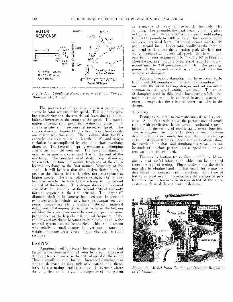
40 lb. �-- 72" --1 .... 12 �· ------bP-Ji !1 ;'d
"A" "8" 1.28
C = 340 lb.- sec. lin. K = 2.0 x 10' lb.! in. Shaft dia. = 6'
oz. in.
10,000·
.. ... c � 1,000·
� .. c ·;:: � 100·
�
0 Speed, 1000 rpm
Figure 11. Unbalance Response of a Shaft for Various Diameter Overhangs.
The previous examples ha1·e shown a general increase in rotor response with speed. This is not surprising considering that the centrifugal force due to the unbalance increases as the square of the speed. The examination of actual rotor performance does not always indicate a greater rotor response at increased speed. The curves shown on Figure 11 ha1·e been drawn to illustrate one reason why this is so. The o1·erhung shaft for this example has been reduced in length to 12", and design variation is accomplished by changing shaft overhang diameter. The factors of spring constant and damping coefficient are. held constant. The same unbalance is used as in previous cases and it is at the end of the overhang. The smallest sized shaft, l-1.-:" diameter, was selected to tune the natural frequencv of the cantilevered overhang to the first natural frequency of the shaft. It will be seen that this design shows a major peak at the first critical with below normal response at higher speeds. The intermediate size shaft, 31,4" diameter, was selected to tune the overhang to the second critical of the system. This design shows an increased sensitivity and response at the second critical and only normal response at the first critical. The larger 6" diameter shaft is the same as has been used in previous examples and is included as a base for comparison purposes. Since there is little damping in the rotor material itself, and all damping is assumed to be in the bearing oil film, the system responses become sharper and more pronounced as the hypothetical natural frequency of the cantilevered overhang becomes more closely tuned to the over-all system natural frequencies. This is one reason why relatively small changes in overhang distance or weight in some cases cause major changes in rotor response.
DAMPING
Damping in oil lubricated bearings is an important factor in the consideration of rotor behavior. Increased damping tends to increase the critical speed of the rotor. This is usually a small factor. Increased damping also tends to decrease the amplitude of vibration, and, therefore, the alternating bearing loading. In systems where the amplification is large, the response of the system
at resonance \1 ill Yary approximately im·ersely with damping. For example. the peak beat·ing loading given in Figure <) for K = 2.0 x 1 0'; pounds inch 11 ould reduce from .J.<>OO pounds to 2-1.00 pounds if the hearing damping were increased from 170 pound-second inch to 3.J.O pound-second inch. l'nder some conditions the damping will tend to eliminate the \'ibration peak which is normally associated 11ith a critical �peed. This is 11 hat happens to the rotor response for K = 0. 7 x 10n in Figure 9 when the bearing damping is increased from l 70 poundsecond 'inch to 3-W pound-second inch. The peak �esponse at the second critical is eliminated with this increase in damping.
Values of hearing damping may he expected to he from about 300 pound-second inch to noo pound-second /
inch with the usual hearing designs and oil 1·iscosities common to high speed rotating equipment. The Yalues of damping used in this stud� ha1·e purposefully been made lower than \1 ould be expected in actual practice in order to emphasize the effect of other 1·ariables in the design.
TESTING Testing is required to correlate anal�·sis with experi
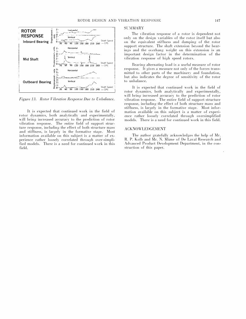
ence. Although correlation of the performance of actual rotors with predictions is the most meaningful type of information, the testing of models has a ll"eiu! function. The arrangement in Figure 12 shows a steam turbine driving a high speed model test rotor through a step up gear. Instrumentation is placed at fire locations along the length of the shaft and simultaneous recordings can be made of the shaft performance as speed or other system variables are changed.
The speed-vibration traces sho\\11 in Figure 13 are one type of useful information 1\hich can he obtained from this type of testing. Phase angles along the shaft may also be obtained and the shaft mode forms may be determined to compare 11ith prediction. This type of testing is most useful in comparing differences of performance for differences in design detail of the rotor system, such as different bearing designs.
Figure 12. Model Rotor Testing for Dynamic Response to Unbalance.
ROTOR DESIGN AND VIBRATION RESPONSE 147
ROTOR RESPONSE
Inboard Bearing
Mid Shaft
I 2> l lt ��0���------------� � ·e 2' Vertical r a. 1 .. � ShaftSpeed S O 30 60 90 120 150 180 210 240 -CPS
� 2 �- Horizontal
� J: /':---� 23' �Vertical � . � 11-g 0 3o 90 120
Horizontal
�
� Shaft Speed 150 180 210 240 -CPS
� Outboard Bearing Vertical L Shaf!Speed 120 150 180 210 240 -CPS
Figure 13. Rotor Vibration Response Due to Unbalance.
It is expected that continued work in the field of rotor dynamics, both analytically and experimentally, will bring increased accuracy to the prediction of rotor vibration response. The entire field of support structure response, including the effect of both structure mass and stiffness, is largely in the formative stage. Most information available on this subject is a matter of experience rather loosely correlated through over-simplified models. There is a need for continued work in this field.
SL\IMARY
The dbration response of a rotor is dependent not only on the design variables of the rotor itself but also on the equivalent stiffness and damping of the rotor support structure. The shaft extension beyond the bearings and the o\·erhang weight on this extension is an important design factor in the determination of the vibration response of high speed rotors.
Bearing alternating load is a useful measure of rotor response. It gives a measure not only of the forces transmitted to other parts of the machinery and foundation, but also indicates the degree of sensitivity of the rotor to unbalance.
It is expected that continued work in the field of rotor dynamics, both analytically and experimentally, will bring increased accuracy to the prediction of rotor vibration response. The entire field of support structure response, including the effect of both structure mass and stiffness, is largely in the formative stage. Most information available on this subject is a matter of experience rather loosely correlated through oversimplified models. There is a need for continued work in this field.
ACKNOWLEDGEMENT
The author gratefully acknowledges the help of Mr. R. P. Kolb and Mr. N. Mizne of De Laval Research and Advanced Product Development Department, in the construction of this paper.