trw space & defense one space park redondo beach, …€¦ · · 2015-10-02systems 1391 rev....
TRANSCRIPT
SYSTEMS 1391 REV. 7-90
TRW Space & Defense One Space ParkRedondo Beach, CA 90278
CAGE CODE NO. 11982
TITLE
PACKAGING SPECIFICATION
PACKAGING OF ELECTROSTATIC DISCHARGE SENSITIVEELECTRONIC PARTS AND COMPONENT ASSEMBLIES
DATE 18 May 2001 NO. PK4-35REV. G
SUPERSEDING: PK4-35F
1 December 1999
PREPARED BY: R.L. Billett/M. Feeney/E.V. Laguette
APPROVAL SIGNATURES:
R.L. Billett 8/30/84 B.B. Evans 8/30/84DATE DATE
C.J. Holzbauer 9/5/84 D.J. Bigelow 9/6/84DATE DATE
W.B. Hallmark 9/5/84 J.A. Morrow 9/6/84DATE DATE
DATE DATE
ORIGINAL PDMO RELEASE:
PD
MOPK
4-35
, G. P
DMO
Rel
ease
d: 2
001-
05-2
1 (V
ERIF
Y RE
VISI
ON
STAT
US).
Page
: 1

TRW Space & Defense One Space ParkRedondo Beach, CA 90278
REVISION/CHANGE RECORD FOR DOCUMENT NO. PK4-35G
SYSTEMS 1391 REV. 7-90
SYMBOL DOCUMENTDATE
AUTHORIZATION / DATE REVISION / CHANGE DESCRIPTION PAGESAFFECTED
--- 9/1/84 See Title Page Initial Release All
A1 12/12/84 Prep. R.L. Billett
Appv. B.B. Evans
Appv. D. Ayala forC.J. Holzbauer
Revised upper resistivity limit in 3.1.5.1 (a).Revised 3.4 for clarification.Revised 6.4.Replace pages 2, 5, and 7
257
A 2/17/89 Prep. R.L. Billett
Appv. B.B. Evans
Appv. C.J. Holzbauer
Added Table of Contents. Numerouschanges to format and requirements inSection 3 effecting lead shorting, carbon-loaded materials, Class 1A parts, RF devicesand semiconductor wafers. Added Figure 11and 12. Revised paragraph 4.4
All
B1 10/19/90 Prep. R.L. Billett
Appv. R.L. Billett
CADMREL.: J. Kroll
Added 1.2. Revised 3.3 to clarify the use ofTable 1. Revised 3.3.9 to provide guidelinefor the use of Figure 9 package. Revised6.5.
1, 2, 6, 7, 11
B 8/12/93 Prep. R.L. Billett
Appv. R.L. Billett
CADMREL.: Signature in file
In paragraphs 2. And 6.2 MIL-STD-1676 wasDOD-STD-1676. In paragraph 3.1.5.1 upperresistivity limit 1 x 10¹² was 1 x 10¹⁴.Paragraph 3.1.5.6 Carbon Loaded Materials,deleted and paragraphs 3.1.5.7 and 3.1.5.8renumbered as 3.1.5.6 and 3.1.5.7.Paragraph 6.4 Resistivity, deleted andparagraph 6.5 renumbered as 6.4.
All
C1 9/17/93 Prep. R.L. Billett
Appv. R.L. Billett
CADMREL.: Signature in file
Added subparagraph (e) under paragraph3.1.5.5.Deleted references to Figure 7 in Table I.Deleted paragraph 3.3.7. Figure 7 is not tobe used as an approved packaging method.
4
67
C 12/7/94 Prep. R.L. Billett
Appv. R.L. Billett
CADMREL.: Signature in file
Revised Table I to add references to Figure7. Added paragraph 3.3.7. Revised Figure 7to depict the description in paragraph 3.3.7.Incorporated SCN C1.
All
PD
MOPK
4-35
, G. P
DMO
Rel
ease
d: 2
001-
05-2
1 (V
ERIF
Y RE
VISI
ON
STAT
US).
Page
: 2
TRW Space & Defense One Space ParkRedondo Beach, CA 90278
REVISION/CHANGE RECORD FOR DOCUMENT NO. PK4-35G
SYSTEMS 1392 REV. 7-90 (FILE DIRECTLY AFTER COVER SHEET)
SYMBOL DOCUMENTDATE
AUTHORIZATION / DATE REVISION / CHANGE DESCRIPTION PAGESAFFECTED
D 12/22/97 Prep. R.L. Billett
Appv. R.L. Billett
CADMREL.: Signature in file
Revised para. 3.1.5.5 to allow the use ofcarbon loaded polyethylene foam and toclarify prohibited materials. Added para.3.1.5.8 to define insulating materials.Revised para. 3.6.4 to add reference to EIAStandard RS-471 for label. Changedreferences from anti-static materials to staticdissipative materials in a number ofparagraphs to conform to current industrypractice. Minor non-technical editorialchanges in a number of paragraphs.
All
E 7/13/99 Prep: R. L. Billett Materials Technology & Engineering
Appv: B. JW. Brooks Materials Technology & Engineering
Cover Sheet and RCR Pages are electronicreproductions of the originals.
Made minor editorial changes.
Broadened document applicability in 1.1 toinclude parts not susceptible to damage fromESD, but used in areas controlling ESD.
Added EIA-625 to 6.2. Added ESD S11.11 toSection 2 and to 3.1.5.1.
Changed 3.1.8 from Class 1A Parts to HighlySensitive Parts.
Changed 3.1.8.1 from Static DissipativeMaterials to Static Shielded Bags. Removedreference to static dissipative materials andASTM D257.
Added, “as provided in paragraph 3.1.3” to3.2.1.
Deleted “maximum quantity of 20 parts perunit package” from 3.2.1.
Removed requirement for placing staticdissipative plastic film over cavities beforeclosing carrier in 3.3.4, now optional.
Added, “To simplify future handling…” to3.3.4.
Added (f), Lot Number or Date Code to 3.6.2for intermediate containers.
Removed 6.4.
Cover Sheet,RCR Pages
All
1
3
5
5
5
5
7
7
8
9
PD
MOPK
4-35
, G. P
DMO
Rel
ease
d: 2
001-
05-2
1 (V
ERIF
Y RE
VISI
ON
STAT
US).
Page
: 3
TRW Space & Defense One Space ParkRedondo Beach, CA 90278
REVISION/CHANGE RECORD FOR DOCUMENT NO. PK4-35G
SYSTEMS 1392 REV. 7-90 (FILE DIRECTLY AFTER COVER SHEET)
SYMBOL DOCUMENTDATE
AUTHORIZATION / DATE REVISION / CHANGE DESCRIPTION PAGESAFFECTED
F 12/1/99 Prep: R. L. Billett Materials Technology & Engineering
Appv: B. JW. Brooks Materials Technology & Engineering
In paragraph 3.1.5.1(b), “static decay time”was “static decay rate”.
Added paragraph 3.1.5.5 (g) to prohibit theuse of PVC plastics.
Added paragraph 6.4.
4
5
9
G 5/18/01 Prep: R. L. Billett Materials Technology & Engineering
Appv: B. JW. Brooks Materials Technology & Engineering
1.1 Added voltage criteria to define ESDsensitivity and deleted reference to TRWdrawing M283308.2. Added TRW Specifications PK4-17, PK4-20, & PK4-21 and deleted NASA test methodMMA-1985-79 and TRW Drawing M283308in Applicable Documents section.3.1.5.5 Revised to add description andguidance for prohibited materials.3.1.5.5 (e) Added materials which containamines and amides to prohibited items.3.1.5.5 (g) Deleted prohibition of chloridecontaining plastics except forpolyvinylchloride.Added 3.1.5.5.(h) to prohibit certain types ofplastic bags and film.Deleted paragraphs 3.1.8, 3.1.8.1, & 3.1.8.2which provided additional packagingrequirements for highly sensitive parts.Added 3.1.8 to provide for additionalrequirements imposed by procurementdocuments.3.3.4 Revised to delete recommendation forthe maximum parts per carrier.Minor editorial changes in a number oflocations.
1
2,3
5
5
5
5
5
5
7
PD
MOPK
4-35
, G. P
DMO
Rel
ease
d: 2
001-
05-2
1 (V
ERIF
Y RE
VISI
ON
STAT
US).
Page
: 4
PK4-35G18 May 2001
i
TABLE OF CONTENTS
Page
1. SCOPE ......................................................................................................... 11.1 Scope ......................................................................................................... 11.2 Purpose ......................................................................................................... 1
2. APPLICABLE DOCUMENTS ......................................................................................... 2
3. REQUIREMENTS ......................................................................................................... 43.1 General ......................................................................................................... 4
3.1.1 Processes .......................................................................................... 43.1.2 Cleaning............................................................................................. 43.1.3 Pairs, Sets, and Kits........................................................................... 43.1.4 Hardware ........................................................................................... 43.1.5 Packaging Materials........................................................................... 4
3.1.5.1 Anti-Static Materials............................................................. 43.1.5.2 Shielding Materials .............................................................. 43.1.5.3 Lead Shorting ...................................................................... 43.1.5.4 Static Shielded Bags............................................................ 43.1.5.5 Prohibited Materials ............................................................. 53.1.5.6 Corrosivity............................................................................ 53.1.5.7 Solderability ......................................................................... 53.1.5.8 Insulating Materials.............................................................. 5
3.1.6 Electrostatic Discharge (ESD) Protection ........................................... 53.1.7 Connectors......................................................................................... 53.1.8 Procurement Documentation.............................................................. 5
3.2 Unit Package Design ........................................................................................ 63.2.1 Quantity.............................................................................................. 63.2.2 Physical Protection............................................................................. 63.2.3 Removal and Replacement Capability................................................ 63.2.4 Documentation ................................................................................... 6
3.3 Unit Package Selection..................................................................................... 63.3.1 Figure 1.............................................................................................. 63.3.2 Figure 2.............................................................................................. 73.3.3 Figure 3.............................................................................................. 73.3.4 Figure 4.............................................................................................. 73.3.5 Figure 5.............................................................................................. 73.3.6 Figure 6.............................................................................................. 73.3.7 Figure 7.............................................................................................. 73.3.8 Figure 8.............................................................................................. 73.3.9 Figure 9.............................................................................................. 73.3.10 Figure 10.......................................................................................... 73.3.11 Figure 11.......................................................................................... 83.3.12 Figure 12.......................................................................................... 8
3.4 Intermediate Container ..................................................................................... 83.5 Shipping Containers ......................................................................................... 8
PD
MOPK
4-35
, G. P
DMO
Rel
ease
d: 2
001-
05-2
1 (V
ERIF
Y RE
VISI
ON
STAT
US).
Page
: 5

PK4-35G18 May 2001
ii
TABLE OF CONTENTS (Continued)
Page
3.6 Marking ......................................................................................................... 83.6.1 Unit Packages.................................................................................... 83.6.2 Intermediate Containers ..................................................................... 83.6.3 Shipping Containers........................................................................... 93.6.4 Electrostatic Discharge Sensitive Marking.......................................... 9
3.7 Workmanship ................................................................................................... 9
4. QUALITY ASSURANCE PROVISIONS.........................................................................104.1 Inspection Responsibility .................................................................................104.2 Acceptance Inspection Procedures..................................................................104.3 Visual Examination ..........................................................................................104.4 Certification......................................................................................................10
5. PREPARATION FOR DELIVERY..................................................................................10
6. NOTES ........................................................................................................................106.1 Intended Use ...................................................................................................106.2 ESD Control Programs ....................................................................................106.3 Topical Antistats ..............................................................................................106.4 Changes from Previous Issue..........................................................................10
Table
TABLE I - UNIT PACKAGE SELECTION GUIDE................................................................ 6
Figures
Figure 1 ............................................................................................................................11Figure 2 ............................................................................................................................11Figure 3 ............................................................................................................................12Figure 4 ............................................................................................................................12Figure 5 ............................................................................................................................13Figure 6 ............................................................................................................................13Figure 7 ............................................................................................................................14Figure 8 ............................................................................................................................14Figure 9 ............................................................................................................................15Figure 10............................................................................................................................15Figure 11............................................................................................................................16Figure 12............................................................................................................................16
PD
MOPK
4-35
, G. P
DMO
Rel
ease
d: 2
001-
05-2
1 (V
ERIF
Y RE
VISI
ON
STAT
US).
Page
: 6
PK4-35G18 May 2001
1
PACKAGING SPECIFICATION
PACKAGING OF ELECTROSTATIC DISCHARGE SENSITIVEELECTRONIC PARTS AND COMPONENT ASSEMBLIES
1.0 SCOPE
1.1 Scope. This specification establishes requirements for the preservation,packaging, electrostatic discharge protection, packing and container marking forelectronic parts and component assemblies which are subject to damage fromelectrostatic discharge (ESD). These items are referred to herein as parts. The partsapplicable to this specification are those susceptible to damage or degradation fromESD voltages of less than 16,000 volts. This specification may also apply to parts whichare not susceptible to damage from ESD but which are used in areas requiring controlof ESD.
1.2 Purpose. The purpose of this specification is to provide requirements andguidance for the application of protective packaging to electronic parts, which will besuitable for the protection of such parts during initial shipment. In addition, it is intendedthat the packaging will be compatible with subsequent internal handling andtransportation operations of receiving, inspection, testing, storage, kitting and issue tomanufacturing for assembly.
G
PD
MOPK
4-35
, G. P
DMO
Rel
ease
d: 2
001-
05-2
1 (V
ERIF
Y RE
VISI
ON
STAT
US).
Page
: 7
PK4-35G18 May 2001
2
2. APPLICABLE DOCUMENTS
The following documents form a part of this specification to the extent specified herein.Unless otherwise specified in the issue in effect on the date of procurement placementshall apply.
STANDARDS
Federal
Federal Test MethodStandard 101
Test Procedures for Packaging Materials
Military
MIL-HDBK-1547 Parts, Materials and Processes forSpace & Launch Vehicles, TechnicalRequirements for
MIL-STD-129 Marking for Shipment and Storage
MIL-STD-1686 Electrostatic Discharge Control Programfor Protection of Electrical and ElectronicParts, Assemblies & Equipment
American Society for Testing and Materials (ASTM)
ASTM D257 D-C Resistance or Conductance ofInsulating Materials
ASTM D991 Volume Resistivity of ElectricallyConductive and Anti-Static Products
Electronics Industries Association
EIA-625 Requirements for Handling ElectrostaticDischarge Sensitive (ESDS) Devices
RS-471 Symbol and Label for ElectrostaticSensitive Items
Electrical Overstress/Electrostatic Discharge Association (EOS/ESD)
ESD S11.11 Surface Resistance Measurement ofStatic Dissipative Planar Materials
PD
MOPK
4-35
, G. P
DMO
Rel
ease
d: 2
001-
05-2
1 (V
ERIF
Y RE
VISI
ON
STAT
US).
Page
: 8
PK4-35G18 May 2001
3
SPECIFICATIONS
TRW Space & Electronics Group
PK4-17 Packaging of Small Electronic Parts inWaffle Packs
PK4-20 Packaging of Small Electronic Partson Tape and Reel Packages forAutomated Assembly
PK4-21 Packaging of Small Electronic Parts inMatrix Trays
G
PD
MOPK
4-35
, G. P
DMO
Rel
ease
d: 2
001-
05-2
1 (V
ERIF
Y RE
VISI
ON
STAT
US).
Page
: 9
PK4-35G18 May 2001
4
3. REQUIREMENTS
3.1 General.
3.1.1 Processes. All packaging and related activities including cleaning,preservation, packaging and packing shall be conducted in a manner to insure thatthere is no degradation or physical damage including electrostatic discharge damage tothe parts (see 6.2).
3.1.2 Cleaning. Parts shall be clean prior to packaging. When cleaning isrequired it shall be accomplished by a process or combination of processes, which willremove contaminants without causing degradation or damage including electrostaticdischarge damage.
3.1.3 Pairs, Sets, and Kits. Parts furnished in pairs, sets, or kits under one partidentification number shall be unit packaged as one pair, one set, or one kit, asapplicable. The package design shall prevent part damage from contact with otherparts contained in the same package.
3.1.4 Hardware. Hardware accompanying a part (brackets, screws, etc.) shallbe protected and enclosed within the unit package in a manner that will not damage thepart or package. When practical, the hardware shall be mounted on the part. Thepackage design shall prevent part damage from contact with other parts contained inthe same package.
3.1.5 Packaging Materials. All packaging materials shall be clean, dry andchemically inert and shall maintain their required properties including static dissipativeproperties throughout normal storage, handling and usage.
3.1.5.1 Static Dissipative Materials. Static dissipative materials used for the unitpackages and in intimate contact with the part shall conform to the following:
(a) Surface resistivity equal to or greater than 1 X 10⁵ but not greater than 1 X10¹² ohms/square in accordance with ASTM D257 or ESD S11.11.
(b) Static decay time of less than 2 seconds in accordance with Federal TestMethod Standard 101 Method 4046.
(c) The material shall be capable of dissipating static charges when groundedwithout the production of a spark.
3.1.5.2 Shielding Materials. Conductive materials used for shielding shall havea surface resistivity of less than 1 X 10⁵ ohms/square in accordance with ASTM D991.
3.1.5.3 Lead Shorting. Material, when used for shorting or shunting of partleads to each other, shall be a conductive material having a direct resistance of 200ohms or less when measured with an ohmmeter with test probes approximately 3/4 inchapart.
3.1.5.4 Static Shielding Bags. Static shielding bags as specified in the unitpackage descriptions shall consist of three (3) layers or laminations with a staticdissipative inner layer and one of the following options:
(1) A continuous conductive exterior layer and an insulating intermediate layer or
(2) A static dissipative exterior layer and a continuous conductive intermediatelayer.
Heat sealed bags shall be of a size to permit opening and resealing a minimum of two(2) times.
PD
MOPK
4-35
, G. P
DMO
Rel
ease
d: 2
001-
05-2
1 (V
ERIF
Y RE
VISI
ON
STAT
US).
Page
: 10

PK4-35G18 May 2001
5
3.1.5.5 Prohibited Materials. Packaging materials that may contaminate,damage, or degrade parts by chemical degradation, outgassing, particle shedding, ordiffusion during long term storage shall not be used in unit packages. Materialsprohibited in unit packages include:
(a) Carbon loaded plastic film except as the conductive layer or lamination withina static shielding bag as described in paragraph 3.1.5.4.
(b) Carbon loaded polyurethane foam. Cross linked polyethylene foam whichcontains carbon is acceptable.
NOTE: Carbon loaded plastic foams can generally beidentified by their dark black color.
(c) Materials which will easily shed conductive particles.
(d) Materials which have been treated with a topical antistat. (See 6.3)
(e) Materials which contain amines, amides, or n-octanoic acid or its precursor.
(f) Fiberboard or paperboard products which are in direct or intimate contact withthe part contained.
(g) Polyvinylchloride (PVC) plastics.
(h) Surfactant added plastic bags or film materials commonly known as pinkpoly.
3.1.5.6 Corrosivity. Materials used for or within unit packages shall be non-corrosive in accordance with Federal Test Method Standard 101 Method 3005.
3.1.5.7 Solderability. Materials used shall not affect part solderability as definedin the applicable part specification.
3.1.5.8 Insulating Materials. Packaging materials identified herein as insulatingshall have a surface resistivity greater than 1 X 10¹² ohms/square in accordance withASTM D257.
3.1.6 Electrostatic Discharge (ESD) Protection. All parts shall be provided withprotection from ESD as described herein. ESD protection shall be provided by the useof a combination of static dissipative packaging materials to prevent the generation ofelectrostatic charges and conductive materials for shielding which provides acontinuous conductive shield enclosing the part.
3.1.7 Connectors. Parts (RF Devices) that have coaxial connectors shall haveconnector covers made from a static dissipative plastic material installed on allconnectors.
3.1.8 Procurement Documentation. In addition to the requirements containedherein, packaging shall conform to specific requirements contained within theprocurement documentation (part specifications, purchase order statement of work,etc.) when those requirements are more specific than the requirements containedherein. When packaging specification PK4-17, PK4-20, or PK4-21 is specified in theprocurement documentation (to support automated assembly equipment), thatspecification shall take precedence over the requirements in this specification andconformance to PK4-17, PK4-20, or PK4-21 as applicable, shall be used as criteria foracceptance.
G
G
G
G
PD
MOPK
4-35
, G. P
DMO
Rel
ease
d: 2
001-
05-2
1 (V
ERIF
Y RE
VISI
ON
STAT
US).
Page
: 11
PK4-35G18 May 2001
6
3.2 Unit Package Design
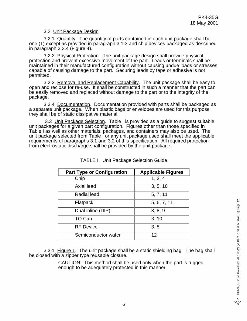
3.2.1 Quantity. The quantity of parts contained in each unit package shall beone (1) except as provided in paragraph 3.1.3 and chip devices packaged as describedin paragraph 3.3.4 (Figure 4).
3.2.2 Physical Protection. The unit package design shall provide physicalprotection and prevent excessive movement of the part. Leads or terminals shall bemaintained in their manufactured configuration without causing undue loads or stressescapable of causing damage to the part. Securing leads by tape or adhesive is notpermitted.
3.2.3 Removal and Replacement Capability. The unit package shall be easy toopen and reclose for re-use. It shall be constructed in such a manner that the part canbe easily removed and replaced without damage to the part or to the integrity of thepackage.
3.2.4 Documentation. Documentation provided with parts shall be packaged asa separate unit package. When plastic bags or envelopes are used for this purposethey shall be of static dissipative material.
3.3 Unit Package Selection. Table I is provided as a guide to suggest suitableunit packages for a given part configuration. Figures other than those specified inTable I as well as other materials, packages, and containers may also be used. Theunit package selected from Table I or any unit package used shall meet the applicablerequirements of paragraphs 3.1 and 3.2 of this specification. All required protectionfrom electrostatic discharge shall be provided by the unit package.
TABLE I. Unit Package Selection Guide
Part Type or Configuration Applicable FiguresChip 1, 2, 4
Axial lead 3, 5, 10
Radial lead 5, 7, 11
Flatpack 5, 6, 7, 11
Dual inline (DIP) 3, 8, 9
TO Can 3, 10
RF Device 3, 5
Semiconductor wafer 12
3.3.1 Figure 1. The unit package shall be a static shielding bag. The bag shallbe closed with a zipper type reusable closure.
CAUTION: This method shall be used only when the part is ruggedenough to be adequately protected in this manner.
PD
MOPK
4-35
, G. P
DMO
Rel
ease
d: 2
001-
05-2
1 (V
ERIF
Y RE
VISI
ON
STAT
US).
Page
: 12

PK4-35G18 May 2001
7
3.3.2 Figure 2. The unit package shall be a static shielding bag. The bag shallbe closed by a heat seal or other suitable means.
CAUTION: This method shall be used only when the part is ruggedenough to be adequately protected in this manner.
3.3.3 Figure 3. The unit package shall be 2-piece molded static dissipativeholding device that incorporates a blister cavity or compartment to provide partprotection. Closure of the holding device shall be by friction locks or similar means thatmeet the requirements of paragraph 3.2.3. Each holding device shall be placed in anindividual heat-sealed or zipper sealed static shielding bag.
3.3.4 Figure 4. The unit package shall be a two-piece, dustproof carrier madefrom conductive or static dissipative material formed with individual cavities. No morethan one part shall be placed into each cavity. A sheet of static dissipative plastic filmor other suitable material may be placed over the cavities before closing the carrier.The closure shall be by friction locks, clips or similar means. Each carrier shall beplaced in a static shielding bag.
3.3.5 Figure 5. The unit package shall be a rigid or semi-rigid static dissipativeplastic box with preformed 2 or 3-piece static dissipate cushioning inserts. Each boxshall be placed in an individual static shielding bag.
3.3.6 Figure 6. The unit package shall be a suitable rigid static dissipativecarrier that protects and maintains lead configuration. A clip or other holding deviceshall secure the part in the carrier. Each carrier shall be placed in an individual staticshielding bag.
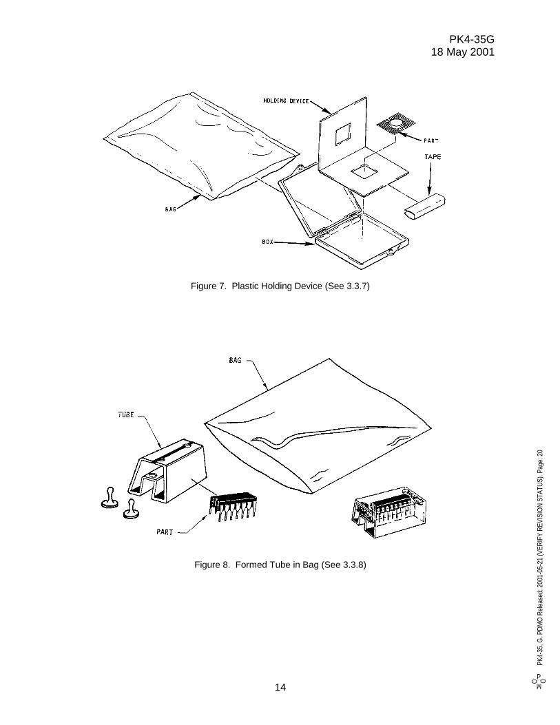
3.3.7 Figure 7. The unit package shall consist of a holding device made from arigid static dissipative plastic material, folded or hinged in half. Cut outs shall beprovided in the holding device for the body of the part. The two halves shall be securedin a closed position using static dissipative pressure sensitive tape. The materialselected and the design of the holding device shall protect the leads and body of thedevice from damage. Each holding device shall be placed in a rigid or semi-rigid staticdissipative plastic box. Each plastic box shall be placed in an individual static shieldingbag.
3.3.8 Figure 8. The unit package shall be a conductive or static dissipative tube(rail) formed to provide physical protection to the part. The part shall be secured in thetube by plugs, pins, static dissipative foam or other means. Each tube shall be placedin an individual static shielding bag. NOTE: Only one part shall be packaged in eachtube and bag combination.
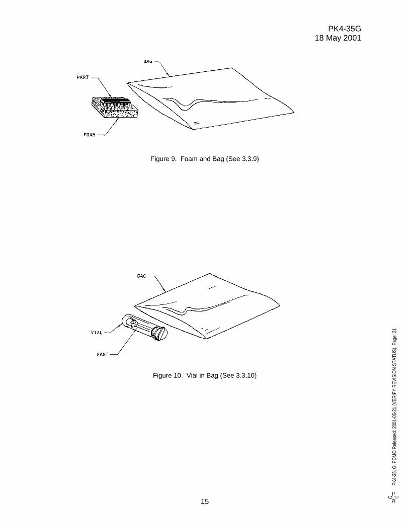
3.3.9 Figure 9. The unit package shall consist of a piece of static dissipativefoam into which the part leads are inserted. Each part with foam shall be placed in anindividual static-shielding bag.
CAUTION: This method shall only be used for parts which have leadsrugged enough to withstand insertion and removal from the foam withoutdamage and which have cases rugged enough to be properly protected inthis manner. As a guideline, this packaging method should not be usedfor parts with leads that project more than 0.5 inch from the part body.
3.3.10 Figure 10. The unit package shall be a static dissipative tube or vial intowhich the part is placed with static dissipative cushioning inserts to secure the part.Each tube or vial shall be placed in an individual static shielding bag.
G
PD
MOPK
4-35
, G. P
DMO
Rel
ease
d: 2
001-
05-2
1 (V
ERIF
Y RE
VISI
ON
STAT
US).
Page
: 13
PK4-35G18 May 2001
8
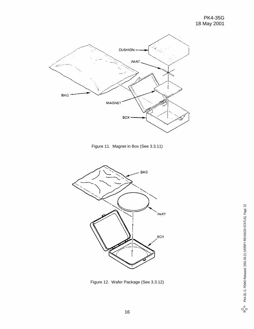
3.3.11 Figure 11. The unit package shall be a static dissipative plastic box witha rubber permanent magnet secured to the inside bottom of the box that holds the partin place. Each closed plastic box shall be placed into an individual static shielding bag.
CAUTION: This method shall be used only with lightweight parts that willbe adequately secured by the magnet. A static dissipative foam-cushioning padmay be used to help hold the part in place.
3.3.12 Figure 12. The unit package shall be a static dissipative plastic box thatholds the part in a manner to prevent movement and protect critical surfaces. Eachclosed plastic box shall be placed in an individual static shielding bag.
3.4 Intermediate Container. The use of intermediate containers for partspackaged in unit containers in accordance with paragraph 3.3, is optional except thatthey are required whenever different part numbers are consolidated for one shipment.Unit packages containing identical parts shall be uniformly loaded into a paperboard orfiberboard folding or setup box. Voids shall be filled using a clean, non-dusting, andchemically neutral cushioning material. Plastic materials in direct contact with the unitpackages shall be static dissipative. Gross packed weight for paperboard or fiberboardintermediate containers shall not exceed their design specification.
3.5 Shipping Containers. Only fiberboard boxes bearing the boxmaker’scertificate in accordance with applicable freight classifications shall be used as exteriorshipping containers. The gross weight limit indicated in the box certificate shall not beexceeded.
3.6 Marking. All containers shall be legibly and durably labeled, tagged, ormarked to show the information specified in the following paragraphs. It is notnecessary to duplicate marking on the unit package when it is clearly visible on the partwithout opening the package.
3.6.1 Unit Packages. Unit packages shall show the following information:
(a) TRW Part Identification Number
(b) Manufacturer’s Name, Initials, or Trademark
(c) Nomenclature
(d) Electrostatic-Sensitive Device Label (see paragraph 3.6.4)
Special marking, when applicable, shall include:
(e) Serial Number
(f) Lot Number or Date Code
(g) Electrical Rating
3.6.2 Intermediate Containers. Intermediate containers (when used) shall showthe following information:
(a) TRW Part Identification Number
(b) Purchase Order or Contract Number
(c) Nomenclature
(d) Quantity of parts contained
(e) Electrostatic-Sensitive Device Label (see paragraph 3.6.4)
(f) Lot Number or Date Code
PD
MOPK
4-35
, G. P
DMO
Rel
ease
d: 2
001-
05-2
1 (V
ERIF
Y RE
VISI
ON
STAT
US).
Page
: 14
PK4-35G18 May 2001
9
3.6.3 Shipping Containers. Shipping containers shall show the followinginformation:
(a) TRW Purchase Order or Contract Number
(b) Manufacturer’s Name and Identifying Code
(c) Electrostatic-Sensitive Device Label (see paragraph 3.6.4)
(d) Shipping documentation (packing slips) shall indicate the quantity of eachpart number contained in the shipment if not included in the shippingcontainer marking.
3.6.4 Electrostatic Discharge Sensitive Marking. Marking and labeling shallclearly show the sensitive nature of the parts contained. The applicable labelrequirements of MIL-STD-129 or EIA Standard RS-471 are preferred; however, otherdistinctive labels of a similar nature are acceptable.
3.7 Workmanship. The packaging, packing, electrostatic discharge protection,and marking shall be of uniform good quality and free from defects that will impairservice life and appearance.
PD
MOPK
4-35
, G. P
DMO
Rel
ease
d: 2
001-
05-2
1 (V
ERIF
Y RE
VISI
ON
STAT
US).
Page
: 15

PK4-35G18 May 2001
10
4. QUALITY ASSURANCE PROVISIONS
4.1 Inspection Responsibility. The supplier is responsible for the performance ofall inspection requirements as necessary to ensure conformance to this specification.TRW reserves the right to perform any inspection where such inspections are deemednecessary to assure that materials and processes conform to prescribed requirements.
4.2 Acceptance Inspection Procedures. Inspection shall be as specified herein.Shipments that do not conform to the requirements specified herein shall be rejected.
4.3 Visual Examination. Packages shall be examined to verify that the package,packaging materials, orientation of parts, and container markings are in accordancewith the requirements specified in Section 3 of this specification.
4.4 Certification. The supplier shall provide certification that the packagingmethods and materials used for providing electrostatic discharge protection conform tothe requirements of this specification. The supplier’s standard certificate of complianceissued with each product shipment will be interpreted to include compliance to therequirements of this specification.
5. PREPARATION FOR DELIVERY
Not applicable
6. NOTES
6.1 Intended Use. This specification is intended for use by manufacturers andsuppliers of electrostatic discharge sensitive electronic parts to TRW as generalrequirements for packaging.
6.2 ESD Control Programs. Additional information and guidance in establishingand maintaining an ESD control program including processes, handling and packagingcan be found in MIL-HDBK-1547 , EIA-625, and MIL-STD-1686.
6.3 Topical Antistats. Topical antistats as referred to herein are those materialsapplied to the surfaces by brushing, dipping or spraying. They generally consist of aliquid solvent carrier and a primary material that is deposited on the surface to performa static control function.
6.4 Changes from Previous Issue. A vertical line in the right hand margin isused in this revision to identify changes with respect to the previous issue.
PD
MOPK
4-35
, G. P
DMO
Rel
ease
d: 2
001-
05-2
1 (V
ERIF
Y RE
VISI
ON
STAT
US).
Page
: 16

PK4-35G18 May 2001
11
Figure 1. Reclosable Bag (See 3.3.1)
Figure 2. Bag (See 3.3.2)
PD
MOPK
4-35
, G. P
DMO
Rel
ease
d: 2
001-
05-2
1 (V
ERIF
Y RE
VISI
ON
STAT
US).
Page
: 17

PK4-35G18 May 2001
12
Figure 3. Holding Device in Bag (See 3.3.3)
Figure 4. Chip Carrier (See 3.3.4)
PD
MOPK
4-35
, G. P
DMO
Rel
ease
d: 2
001-
05-2
1 (V
ERIF
Y RE
VISI
ON
STAT
US).
Page
: 18

PK4-35G18 May 2001
13
Figure 5. Cushioned Box in Bag (See 3.3.5)
Figure 6. Carrier in Bag (See 3.3.6)
PD
MOPK
4-35
, G. P
DMO
Rel
ease
d: 2
001-
05-2
1 (V
ERIF
Y RE
VISI
ON
STAT
US).
Page
: 19
PK4-35G18 May 2001
14
Figure 7. Plastic Holding Device (See 3.3.7)
Figure 8. Formed Tube in Bag (See 3.3.8)
PD
MOPK
4-35
, G. P
DMO
Rel
ease
d: 2
001-
05-2
1 (V
ERIF
Y RE
VISI
ON
STAT
US).
Page
: 20
PK4-35G18 May 2001
15
Figure 9. Foam and Bag (See 3.3.9)
Figure 10. Vial in Bag (See 3.3.10)
PD
MOPK
4-35
, G. P
DMO
Rel
ease
d: 2
001-
05-2
1 (V
ERIF
Y RE
VISI
ON
STAT
US).
Page
: 21
PK4-35G18 May 2001
16
Figure 11. Magnet in Box (See 3.3.11)
Figure 12. Wafer Package (See 3.3.12)
PD
MOPK
4-35
, G. P
DMO
Rel
ease
d: 2
001-
05-2
1 (V
ERIF
Y RE
VISI
ON
STAT
US).
Page
: 22