trike conversion installation guide indian...
TRANSCRIPT

Trike Conversion Installation Guide
Indian Chieftain/Roadmaster/Classic/Vintage 2014+
Independent Suspension Rev. 3 – March 11, 2016
CAUTION: -Failure to make the proper adjustments will potentially lead to serious personal injury and/or property damage and may void the warranty. -Champion does not guarantee fit form or function to any of their trike kits if altered or aftermarket components were added to the original bike design. -All dealers or installers should make proper adjustments with the customer before delivery. Champion is not responsible for additional adjustments made under warranty.
Champion Motorcycle Accessories International, Inc.
dba Champion Sidecars
11841 Monarch Street, CA 92841 (800) 875-0949 (714) 847-0949 Fax (714) 847-1539
www.championtrikes.com

INDIAN TRIKE CONVERSION
CHAMPION TRIKES
Installation Guide – Indian 2014+ Page 2 of 27 Rev 2
Contents
1 General Information .............................................................................................................................................3 1.1 Installation Information ................................................................................................................................3 1.2 Altered or Changed from OEM Warning .....................................................................................................3 1.3 For Your Safety ...........................................................................................................................................3 1.4 Make sure the engine is turned off before you begin work. ........................................................................3 1.5 Trike Specifications .....................................................................................................................................4
2 Removal of Original Parts ...................................................................................................................................5 3 Installing Trike .....................................................................................................................................................6
3.1 Indian Sub Frame Modification ...................................................................................................................6 3.2 Install Top Frame ........................................................................................................................................6 3.3 Install Rear End ..........................................................................................................................................7 3.4 Install Swing Arm and Body Frame ............................................................................................................8 3.5 Install Support Frame and Struts ............................................................................................................. 10
4 Align and Tension Drive Belt ............................................................................................................................ 13 5 Anti-Roll Bar Installation ................................................................................................................................... 14
5.1 Standard Roll Bar Installation .................................................................................................................. 14 6 Brake System Installation ................................................................................................................................. 15 7 Exhaust System Installation ............................................................................................................................. 15 8 Exhaust Cover Installation ................................................................................................................................ 17 9 Side Cover Installation ..................................................................................................................................... 18 10 E-Brake Installation ...................................................................................................................................... 19 11 Body Installation .......................................................................................................................................... 20 12 Seat Installation ........................................................................................................................................... 20 13 Tour Box/Back Rest Installation .................................................................................................................. 22
13.1 Chieftain/Roadmaster Tour Box Installation ............................................................................................ 22 13.2 Chieftain Back Rest Installation ............................................................................................................... 24 13.3 Classic/Vintage Top Box Installation ....................................................................................................... 24 13.4 Classic/Vintage Back Rest Installation .................................................................................................... 24
14 Wheel and Tire Installation .......................................................................................................................... 25 15 Antenna Placement ..................................................................................................................................... 25 16 Install Trailer Hitch Receiver (Optional Accessory) ..................................................................................... 25 17 Shock Adjustment ........................................................................................................................................ 26
17.1 Adjusting Shock Preload.......................................................................................................................... 26

INDIAN TRIKE CONVERSION
CHAMPION TRIKES
Installation Guide – Indian 2014+ Page 3 of 27 Rev 2
1 General Information
The Champion Trike Conversion Kit is designed with the utmost consideration for safety, quality and ease of installation. The kit comes complete with all necessary hardware and fasteners. It is recommended that the installer obtain an OEM service manual for the vehicle on which the Trike kit is to be installed. Please review the installation instructions before installing the kit.
1.1 Installation Information
The information contained in this installation guide is intended for use by technicians of advanced to professional skill levels. Attempting installation without the proper training, tools and equipment may result in damage to the vehicle, cause unsafe conditions, or cause personal injury to you and/or others.
1.2 Altered or Changed from OEM Warning
CAUTION: Champion trike kits are designed for installation on unmodified motorcycles as from the OEM. Champion does not guarantee fit, form, or function, on any of their trike kits if installed with altered or aftermarket parts differing from the original bike design.
1.3 For Your Safety
Because this guide is intended for technicians of advanced to professional skill levels, we do not provide warnings about many basic shop safety practices. If you have not received shop safety training or do not feel confident about your knowledge of safety practices, we recommend that you do not attempt to perform the procedures described in this guide.
Some of the most important general safety precautions are given below. Champion Trikes cannot warn you of every conceivable hazard that can arise. Only you can decide whether or not you should perform a given task. Important Safety Precautions Make sure you have a clear understanding of all basic shop safety practices and that you wear appropriate clothing and use safety equipment. Be especially careful of the following:
Read all directions before you begin, and make sure you have the tools, the parts and the skills required to perform the tasks safely and completely.
Protect your eyes by using proper safety glasses, goggles or face shields anytime you hammer, drill, grind, pry or work around pressurized air or liquids, and springs or other stored-energy components.
Use other protective wear when necessary, for example gloves or safety shoes. Handling hot or sharp parts can cause severe burns or cuts.
Protect yourself and others when you have a vehicle up in the air. Anytime you lift a vehicle, either by hoist or a jack, make sure that it is securely supported.
1.4 Make sure the engine is turned off before you begin work.
Carbon Monoxide poisoning from exhaust gases: Be sure there is adequate ventilation whenever you run the engine.
Burns from hot parts: Let the engine and exhaust system cool before working on those areas.

INDIAN TRIKE CONVERSION
CHAMPION TRIKES
Installation Guide – Indian 2014+ Page 4 of 27 Rev 2
Injury from moving parts: If running the engine, keep hands, fingers and clothing away from moving/rotating parts.
Gasoline vapor and hydrogen gases from batteries are explosive. To reduce the possibility of fire or explosion, be careful when working near gasoline and batteries.
Use only nonflammable solvent, not gasoline, to clean parts
Never drain or store gasoline in an open container.
Keep all cigarettes, sparks or flame away from the battery and all fuel related parts.
1.5 Trike Specifications
Overall Length: 109.5”
Overall Width: 59.5”
Wheel Base: 69”
Max Load Capacity: 600 lbs
Tire Size (15”): 205 / 70 / R15
Wheel Size (15”) (4 lug) Offset +35 mm 15x7JJ 4x4.5
Tire Pressure: 22-25 PSI
Suspension: Double A-Arm Suspension
Rear Belt Champion supplied 165 tooth belt- Part # CH-IN0-009
Rear Axle/Differential: Custom-built rear differential utilizing Supplied 165 tooth drive belt
Brakes: Original front plus 2 high performance disc brakes at rear
Storage Capacity: 5.75 cubic feet ( full-face helmet plus additional storage)

INDIAN TRIKE CONVERSION
CHAMPION TRIKES
Installation Guide – Indian 2014+ Page 5 of 27 Rev 2
2 Removal of Original Parts
Champion does not change components that will affect or change the emission characteristics of the motorcycle. - Secure and raise motorcycle at least 10 inches. - Remove the following from the vehicle for installation. See OEM manual for detailed instructions.
a. Seat (both front and rear)
b. Disconnect battery leads
c. Top Box (if equipped)
d. Saddle Bags
e. Mufflers (and chrome covers over muffler joints if needed)
f. Saddlebag Rails (if so equipped)
g. Top Box Frame and Chrome Covers (if equipped)
h. Passenger Foot Rests
i. Side Body Panels
j. Rear End
Rear Wheel
Swing Arm
Rear Shock
Rear Caliper
NOTE: Prior to disconnecting the line at the caliper, depress the foot brake and secure it in the down position (zip-tie to floor board). This will prevent fluid flow when the rear brake caliper is removed.
k. Disconnect radio antenna in front of gas tank on LH side. Pull cable out from under tank towards the rear of the bike.
l. Rear Fender (Remove the passenger seat catch with bolts from the fender)
m. Remove OEM Drive Belt
- Indentify and label OEM hardware. OEM hardware will be reused for this conversion and is referenced in the following instructions.
INDIAN TRIKE CONVERSION
CHAMPION TRIKES
Installation Guide – Indian 2014+ Page 6 of 27 Rev 2
3 Installing Trike
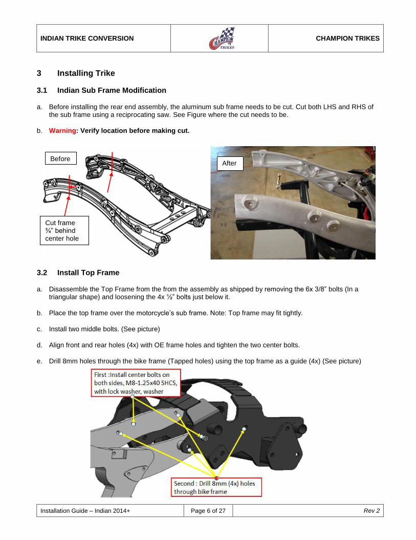
3.1 Indian Sub Frame Modification
a. Before installing the rear end assembly, the aluminum sub frame needs to be cut. Cut both LHS and RHS of the sub frame using a reciprocating saw. See Figure where the cut needs to be.
b. Warning: Verify location before making cut.
3.2 Install Top Frame
a. Disassemble the Top Frame from the from the assembly as shipped by removing the 6x 3/8” bolts (In a triangular shape) and loosening the 4x ½” bolts just below it.
b. Place the top frame over the motorcycle’s sub frame. Note: Top frame may fit tightly.
c. Install two middle bolts. (See picture)
d. Align front and rear holes (4x) with OE frame holes and tighten the two center bolts.
e. Drill 8mm holes through the bike frame (Tapped holes) using the top frame as a guide (4x) (See picture)
Cut frame ¾” behind center hole
Before After

INDIAN TRIKE CONVERSION
CHAMPION TRIKES
Installation Guide – Indian 2014+ Page 7 of 27 Rev 2
f. Install M8 bolts (4x) in the front and rear holes. (See picture)
g. Torque all 6 bolts to 18 ft-lbs
3.3 Install Rear End
a. Remove Swing Arm from rear end and body frame (As shipped) by removing 4x ½”x3/4” Bolts.
b. Install the rear end to the top frame.
c. Use the 3/8-16x1.25 HHCS, w/washers, and nylock nuts. Keep bolts loosely tighteneg for alignment purposes later.
d. Make sure the ½” bolts (4x) are also loose for future belt adjustment.
e. Wrap the belt around the motorcycle front drive pulley.

INDIAN TRIKE CONVERSION
CHAMPION TRIKES
Installation Guide – Indian 2014+ Page 8 of 27 Rev 2
3.4 Install Swing Arm and Body Frame
a. Slide the swing arm between the motorcycle frame and Champion rear end assembly. Warning – Be careful when inserting the swing arm. Avoid bumping the sensors and fittings on the bike. Keep swing arm supported at all times.
b. Insert the pivot bolt (without Jam nut) from the RHS. Use the OEM sleeve.from LHS. (See the cut through picture below – Viewed from the front of the bike)
c. Support swing arm from the Rear End with a ½” 3-3/4” bolt that was previously removed when the swing arm and body frame were removed from the rear end. (As shipped).(See picture below)
d. Tighten Pivot bolt until resistance is being felt (It is bottoming out on Nylon – Be careful) (See picture above)
e. Thread on the OEM nylock nut onto the LHS and torque to 65 ft-lbs.
f. Thread on Jam Nut on the RHS and torque to 75 ft-lbs

INDIAN TRIKE CONVERSION
CHAMPION TRIKES
Installation Guide – Indian 2014+ Page 9 of 27 Rev 2
g. Strap the swing arm to the bike framem, remove the support bolt, and lower the swing arm about 3” at the back end. This allows for easy fitment of the body frame to the swing arm. Warning –Do not let the swing arm drop. Serious damage can be done to the fittings and sensors just below the swing arm pivot bolt.
h. Place the body frame inside of the swing arm and push the1/2-13x3-3/4” HHCS,(4x) bolts and washers through the swing arm and body frame until flush with inside of body frame to secure the body frame to the swing arm.
i. Lift the swing arm and body frame combination and align the four ½” bolts with the slots on the rear end and push bolts (4x) through to secure the swing arm/body frame to the rear end. Add washers and nuts and tighten hardware just enough to allow rear end to move for belt adjustment.
j. Attach the RHS belt adjuster bracket to the swing arm and torque hardware to 26 ft-lbs.
k. Note: For newer models the LHS belt adjuster bracket has been redesigned. Mount the new LHS adjuster bolt bracket onto the swing arm by using a 1/4-20x5/8” HHCS w/washers and nylock nut. Face the bracket towards the rear end and use the 3/8-16x1” HHCS w/washers and nylock nut. Torque the 1/4" bolt to 7ft-lbs and torque the 3/8” bolt to 26ft-lbs. See the figure below.

INDIAN TRIKE CONVERSION
CHAMPION TRIKES
Installation Guide – Indian 2014+ Page 10 of 27 Rev 2
3.5 Install Support Frame and Struts
a. Slide the support frame onto the four tabs of OEM motorcycle frame. Line up the hole of the support frame to the tapped holes. (See pictures)
b. Using the support frame as a template drill an 8mm hole through a tab. Install the correct bolt in the hole to keep the frame from moving and continue with the same process for the other three holes.
c. For the next steps, start on the RHS
d. Warning - When installing the M8 bolt into the Side Panel Pin, It is possible for bolt to “bottom out” before the required clamping between the Bike frame and Support frame is achieved. Install enough M8 washers (supplied) on the inside to make sure to prevent this.

INDIAN TRIKE CONVERSION
CHAMPION TRIKES
Installation Guide – Indian 2014+ Page 11 of 27 Rev 2
e. For the RHS use the M08x1.25x30 SHCS, with (enough) washers, and split washer on the head side. Use the Side Panel Pins that will hold the side panel with a washer and torque to 12 ft-lbs.(2x)
f. For the LHS, use the indicated hardware below and torque to 18 ft-lbs.
g. Install struts from the support frame to the top frame. Using the indicated hardware below, torque all bolts to 40 ft-lbs.
LH Side

INDIAN TRIKE CONVERSION
CHAMPION TRIKES
Installation Guide – Indian 2014+ Page 12 of 27 Rev 2
RH Side

INDIAN TRIKE CONVERSION
CHAMPION TRIKES
Installation Guide – Indian 2014+ Page 13 of 27 Rev 2
4 Align and Tension Drive Belt
a. Set the belt tension and alignment by moving the independent drive train unit forward or rearward as necessary using the adjuster bolts. Belt tension can be measured by total vertical movement and should be approximately ¾”-1” with a new belt.
b. To check the alignment, turn the sprocket by hand in the forward direction, noting if the belt runs in the center of the pulley. If the pulley runs on the right side plate of the pulley, use the right hand adjuster bolts to move the right wheel rearward until the belt runs in the center. If the belt runs on the left side plate of the pulley, use the left adjuster bolts to move the left wheel rearward. Make small adjustments and recheck the alignment.
c. Once the belt is aligned, torque the four front 1/2" fasteners to 70 ft-lbs and double check belt alignment. If alignment is off, please repeat alignment process.
d. Tighten all fasteners left loose for belt adjustment. Torque the four rear ½” fasteners to 70 ft-lbs.
e. Torque the Side Body Mount brackets to Top Frame 3/8-24x1.25” HHCS to 45ft-lbs.Torque the OEM pivot bolt nut to 80 ft-lbs. Recheck belt tension and alignment after tightening the fasteners.
f. If belt is off to the right or left go back to (b).

INDIAN TRIKE CONVERSION
CHAMPION TRIKES
Installation Guide – Indian 2014+ Page 14 of 27 Rev 2
5 Anti-Roll Bar Installation
5.1 Standard Roll Bar Installation
a. Install the four 3/8-24x1” HHCS, w/washers and nuts through anti-roll bar housing onto front frame. Position the anti-roll bar on the frame so that the rod ends will be close to vertical when attached to the control arms.
b. Torque hardware to 45 ft-lbs.
c. Attach rod-end to right control arm with the included hardware in the following order: 3/8-24x2.25” bolt, washer, rod-end, washer, control arm, washer, and then nut. Torque to 45 ft-lbs.
d. Adjust left side rod-end until it aligns with the left control arm mounting hole.
e. Tighten jam nut on the left side rod end assembly.
f. Attach rod end to left control arm just as was done to right control arm. Torque to 45 ft-lbs.
INDIAN TRIKE CONVERSION
CHAMPION TRIKES
Installation Guide – Indian 2014+ Page 15 of 27 Rev 2
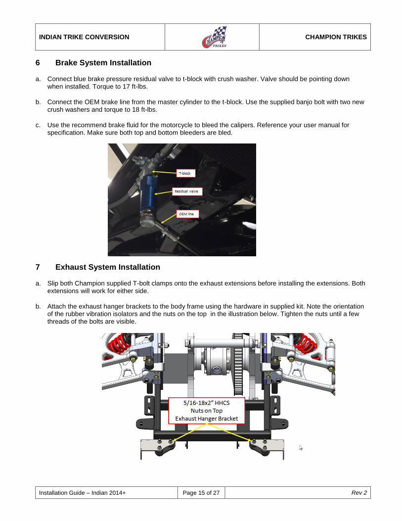
6 Brake System Installation
a. Connect blue brake pressure residual valve to t-block with crush washer. Valve should be pointing down when installed. Torque to 17 ft-lbs.
b. Connect the OEM brake line from the master cylinder to the t-block. Use the supplied banjo bolt with two new crush washers and torque to 18 ft-lbs.
c. Use the recommend brake fluid for the motorcycle to bleed the calipers. Reference your user manual for specification. Make sure both top and bottom bleeders are bled.
7 Exhaust System Installation
a. Slip both Champion supplied T-bolt clamps onto the exhaust extensions before installing the extensions. Both extensions will work for either side.
b. Attach the exhaust hanger brackets to the body frame using the hardware in supplied kit. Note the orientation of the rubber vibration isolators and the nuts on the top in the illustration below. Tighten the nuts until a few threads of the bolts are visible.

INDIAN TRIKE CONVERSION
CHAMPION TRIKES
Installation Guide – Indian 2014+ Page 16 of 27 Rev 2
c. Slide on the OEM exhaust clamps onto both exhaust pipes and connect the exhaust extensions to them. Connect the assembly to the header pipes on both sides. Attach the exhaust pipes to the hanger brackets using the OEM hardware. Torque the OEM hardware to 20 ft-lbs. Torque the T-bolts to 18 ft-lbs. Torque the OEM clamps to 35 ft-lbs .
d. Attach the rubber mounts onto both tabs and torque to 17 ft-lbs.

INDIAN TRIKE CONVERSION
CHAMPION TRIKES
Installation Guide – Indian 2014+ Page 17 of 27 Rev 2
8 Exhaust Cover Installation
a. On the LHS, pull out the OEM hose clamp within the heat shield and guide the 2” (#24) hose clamp. Install the heat shield. Reuse the other clamp and torque both clamps to 48 in-lbs.
b. For the RHS, pull out the OEM hose clamp within the heat shield and guide the supplied 4” (#56) hose clamp.
c. Place the heat shield spacer onto the exhaust extension’s expand section. This would after the OEM clamp that was used to hold the extension in place. Use a 2-3/4” (#36) hose clamp and tighten but keep loose.
d. Place the RHS heat shield over the spacer for fitment. Verify that the spacer will not hit the two weld pieces inside the heat shield.
e. Torque all three clamps to 48 in-lbs.

INDIAN TRIKE CONVERSION
CHAMPION TRIKES
Installation Guide – Indian 2014+ Page 18 of 27 Rev 2
9 Side Cover Installation
a. On the RHS, install bottom side panel. Then attach the RHS footpeg using the OEM hardware. Torque to 35 ft-lbs.
b. For the LHS, drill a 7/16” hole into the lower side panel. Install the lower panel by using the OEM hardware for M8 screw and torque to 18 ft-lbs.

INDIAN TRIKE CONVERSION
CHAMPION TRIKES
Installation Guide – Indian 2014+ Page 19 of 27 Rev 2
10 E-Brake Installation
a. The Emergency brake calipers, balancing bar and cables are pre-installed and adjusted in the factory.
b. Install the E brake onto the (LHS) bike frame using the supplied hardware which is indicated below. Torque the M8 screw to 18 ft-lbs and M6 screw to 8 ft-lbs.
c. Use a zip tie around the body frame to hold down the RHS cable. Use two zip ties to hold the pull cable onto the control arm mount. Note: Make sure the pull cable is not touching the arms or shock.
d. Slip the boot over the hand lever and mounting bracket.
e. Install the LHS passenger footpeg. Torque 35 ft-lbs.

INDIAN TRIKE CONVERSION
CHAMPION TRIKES
Installation Guide – Indian 2014+ Page 20 of 27 Rev 2
11 Body Installation
a. Make sure the two rear rubber mounts are attached to the rear frame and are loose.
b. Place trike body, with front four rubber mounts attached, onto all six mounting locations.
c. Install the hardware as it came shipped and keep loose.
d. Position the trike body to best fit both the rear wheels and bike frame.
e. Only drill or slot the two rear holes in the body larger if necessary.
f. Tighten all six 3/8-16 short nylock nuts to 17 ft. lbs.
g. Connect Champion wire harness to body harness.
h. Connect Champion wire harness to OEM motorcycle wire harness.
12 Seat Installation
a. Turn over the seat and remove the staples near the seat tab. Use a 1/4” drill to drill out both rivets. Remove the destroyed rivets from the seat.
b. Insert the supplied bracket in between the cushion and the seat plate.
Note: The installation/alignment of the body is an iterative process to find the correct position of body in relation to the wheels. The six holes already in the body are primarily for shipping purposes. These holes may line up with the pre-drilled body frame holes when the body is fitted, but may need to be elongated to align body.

INDIAN TRIKE CONVERSION
CHAMPION TRIKES
Installation Guide – Indian 2014+ Page 21 of 27 Rev 2
c. Place the Champion seat tab onto the plastic seat plate. Line up the holes and use two 1/4-20x3/4” BHCS. Torque to 5 ft-lbs.
d. Staple the seat cloth onto the plastic seat plate.
e. Slide the seat onto the trike and using the OEM hardware, torque both side of the seat to 18 ft-lbs.
f. Attach OEM seat using the OEM decorative BHCS and torque to 13 ft-lbs.
INDIAN TRIKE CONVERSION
CHAMPION TRIKES
Installation Guide – Indian 2014+ Page 22 of 27 Rev 2
13 Tour Box/Back Rest Installation
13.1 Chieftain/Roadmaster Tour Box Installation
Note: The Chieftain does not come standard with a Tour Box. To add a Tour Box to a Chieftain purchase the parts in step a) For the Roadmaster model skip to step (b).
a. For the Chieftain purchase the entire tour box package but exclude Indian part # 1020539-156 (ASM., Trunk Side Plate RH, Chrome) and part # 1020538-156 (ASM., Trunk Side Plate RH, Chrome) if possible. Make sure you have both lock lever grips (Indian part #5414785) and both front isolators (Indian part # 5414784). See a local Indian dealership for pricing and availability.
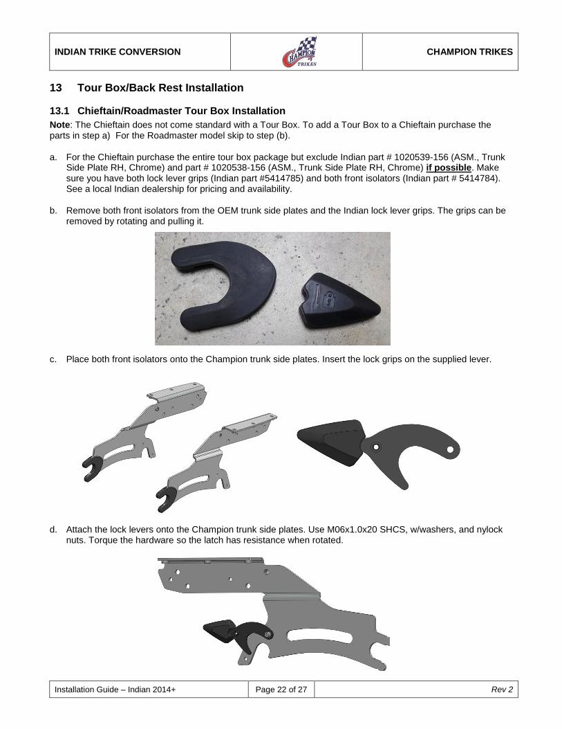
b. Remove both front isolators from the OEM trunk side plates and the Indian lock lever grips. The grips can be removed by rotating and pulling it.
c. Place both front isolators onto the Champion trunk side plates. Insert the lock grips on the supplied lever.
d. Attach the lock levers onto the Champion trunk side plates. Use M06x1.0x20 SHCS, w/washers, and nylock nuts. Torque the hardware so the latch has resistance when rotated.

INDIAN TRIKE CONVERSION
CHAMPION TRIKES
Installation Guide – Indian 2014+ Page 23 of 27 Rev 2
e. Slide the Indian plastic sleeves over the Champion supplied aluminum sleeves. Slide the parts onto the top frame bosses. Apply aggressive adhesive onto plastic cap and snap it into each hole. See Figure.
f. Remove the OEM center support from the top box and attach it onto the Champion trunk side plates. Use the OEM hardware and torque to 18 ft-lbs.
g. Guide the assembly through the body and snapping the back into position. Rotate the locking latches into the locking position.

INDIAN TRIKE CONVERSION
CHAMPION TRIKES
Installation Guide – Indian 2014+ Page 24 of 27 Rev 2
h. Use the supplied M06x1.0x16 HHCS, w/lock washer, and washer. Torque to 8.5 ft-lbs. NOTE: Failure to use the supplied hardware may result in the top box to release when operating the trike.
13.2 Chieftain Back Rest Installation
a. Slide the Indian plastic sleeves over the supplied Champion aluminum sleeves. Slide the parts onto the top frame bosses. Snap in the plastic caps into each hole.
b. Guide the back rest through the body and snap the back into position. Use the Indian hardware to lock the locking latch.
13.3 Classic/Vintage Top Box Installation
a. Follow the Chieftain/Roadmaster tour box.
13.4 Classic/Vintage Back Rest Installation
a. The Indian plastic sleeves need to be modified by 0.10”. Each sleeve should measure roughly to an overall length of 0.94”.

INDIAN TRIKE CONVERSION
CHAMPION TRIKES
Installation Guide – Indian 2014+ Page 25 of 27 Rev 2
b. Slide all four modified sleeves onto the top frame and snap in the plastic caps.
c. Guide the back rest through the body and snap the back into position. Use the Indian hardware to lock the locking latch.
14 Wheel and Tire Installation
a. Install wheels and torque nuts to 75 ft. lbs.
b. Set tire pressure to 22-25 psi
15 Antenna Placement
a. Measuring from the trunk, drill two 3/16” holes into the RHS of the body. See the below figure.
b. Place OEM antenna with rubber seal.
c. Attach OEM wiring to the antenna from the inside of the trunk.
d. Tighten the antenna down to body.
16 Install Trailer Hitch Receiver (Optional Accessory)
a. Install hitch receiver to trike body frame with supplied hardware.
Qty Description
8 5/16"-18 x 1 hex bolts
8 5/16” SAE flat washers.

INDIAN TRIKE CONVERSION
CHAMPION TRIKES
Installation Guide – Indian 2014+ Page 26 of 27 Rev 2
b. Electrical wiring for the trailer is located on the underside of the trike body at the rear. Electrical connectors not supplied. Mounting tab for connector socket is located on hitch receiver.
c. Color code for wiring as follows: (Confirm by testing)
Function Color
Running lights BROWN
Brake lights RED
Turn signal, right GREEN
Turn signal, left YELLOW
Accessory BLUE
Ground BLACK
17 Shock Adjustment
17.1 Adjusting Shock Preload
a. The preload adjuster is factory-set at the softest level for a plush ride. Increasing preload may be advisable if needed for additional weight.
b. To adjust the preload, turn the black collar located on the bottom of the spring just as you would with a fastener with right handed thread. See recommended tool below for adjusting the preload.
Note: Both shock absorbers must be adjusted equally resulting in the equal spring preload. Not having equal adjustments will affect handling that could lead to potential harm.

INDIAN TRIKE CONVERSION
CHAMPION TRIKES
Installation Guide – Indian 2014+ Page 27 of 27 Rev 2
More Preload = Stiffer Ride Less Preload = Softer Ride
c. Recommended spring preload from softest setting as follows:
+1/4” up to 200 lbs.
+1/2” up to 400 lbs.
+5/8” with trailer
d. Champion recommends using a shortened #2 Phillips head screwdriver to adjust spring preload. Tool tip diameter needs to be ¼”.