trapping in two-phase flow in porous media
TRANSCRIPT
V. Joekar-Niasar; F. Doster; J. M. Nordbotten; M. A. Celia
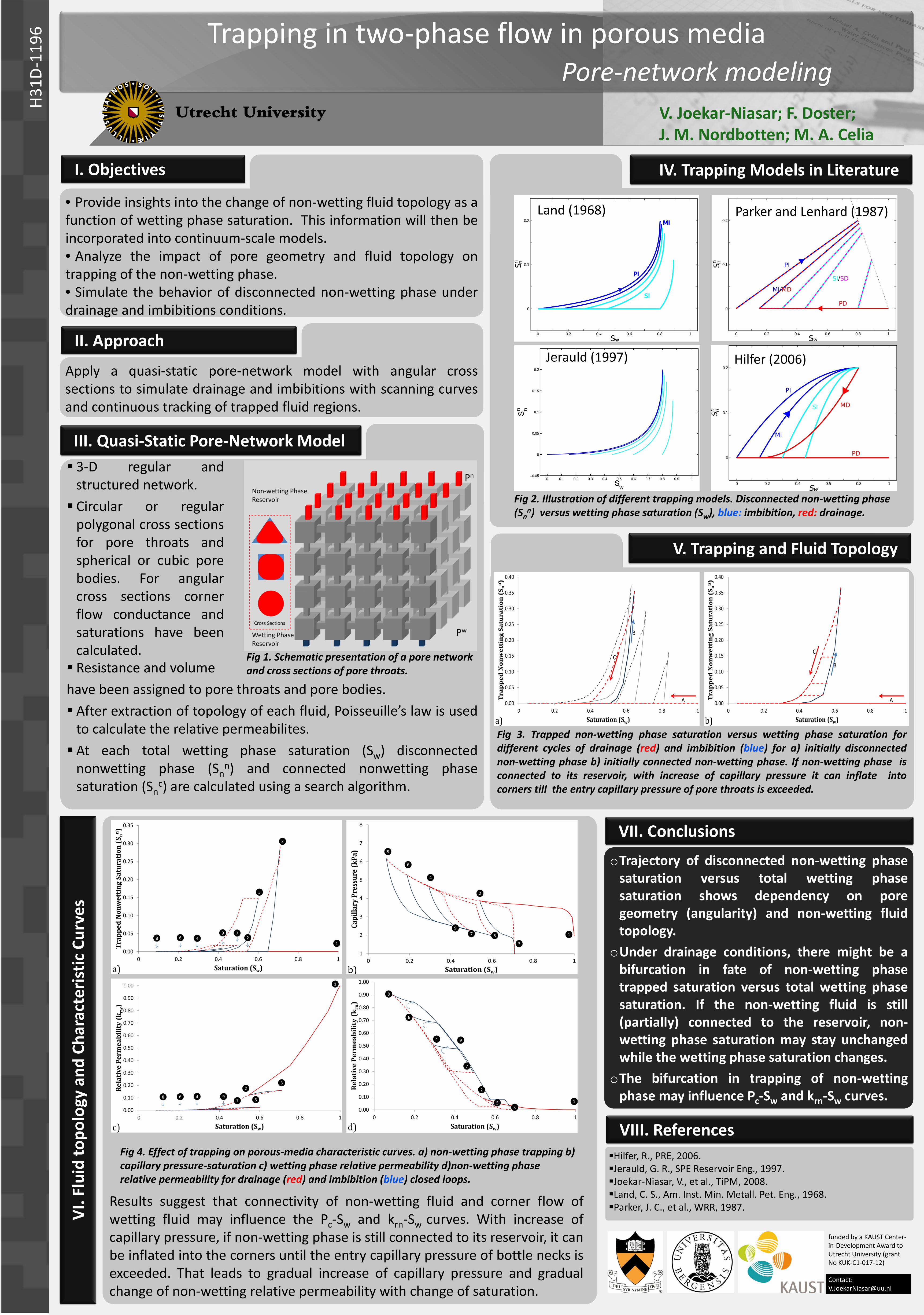
Trapping in two-phase flow in porous media Pore-network modeling
I. Objectives
• Provide insights into the change of non-wetting fluid topology as a function of wetting phase saturation. This information will then be incorporated into continuum-scale models. • Analyze the impact of pore geometry and fluid topology on trapping of the non-wetting phase. • Simulate the behavior of disconnected non-wetting phase under drainage and imbibitions conditions.
II. Approach
Apply a quasi-static pore-network model with angular cross sections to simulate drainage and imbibitions with scanning curves and continuous tracking of trapped fluid regions.
III. Quasi-Static Pore-Network Model
Resistance and volume have been assigned to pore throats and pore bodies. After extraction of topology of each fluid, Poisseuille’s law is used
to calculate the relative permeabilites. At each total wetting phase saturation (Sw) disconnected
nonwetting phase (Snn) and connected nonwetting phase
saturation (Snc) are calculated using a search algorithm.
IV. Trapping Models in Literature
VI. F
luid
topo
logy
and
Cha
ract
erist
ic C
urve
s
VII. Conclusions
oTrajectory of disconnected non-wetting phase saturation versus total wetting phase saturation shows dependency on pore geometry (angularity) and non-wetting fluid topology.
oUnder drainage conditions, there might be a bifurcation in fate of non-wetting phase trapped saturation versus total wetting phase saturation. If the non-wetting fluid is still (partially) connected to the reservoir, non-wetting phase saturation may stay unchanged while the wetting phase saturation changes.
oThe bifurcation in trapping of non-wetting phase may influence Pc-Sw and krn-Sw curves.
H31D
-119
6
3-D regular and structured network. Circular or regular
polygonal cross sections for pore throats and spherical or cubic pore bodies. For angular cross sections corner flow conductance and saturations have been calculated.
Land (1968) Parker and Lenhard (1987)
Hilfer (2006) Jerauld (1997)
Fig 2. Illustration of different trapping models. Disconnected non-wetting phase (Sn
n) versus wetting phase saturation (Sw), blue: imbibition, red: drainage.
V. Trapping and Fluid Topology
Fig 3. Trapped non-wetting phase saturation versus wetting phase saturation for different cycles of drainage (red) and imbibition (blue) for a) initially disconnected non-wetting phase b) initially connected non-wetting phase. If non-wetting phase is connected to its reservoir, with increase of capillary pressure it can inflate into corners till the entry capillary pressure of pore throats is exceeded.
Fig 4. Effect of trapping on porous-media characteristic curves. a) non-wetting phase trapping b) capillary pressure-saturation c) wetting phase relative permeability d)non-wetting phase relative permeability for drainage (red) and imbibition (blue) closed loops.
Results suggest that connectivity of non-wetting fluid and corner flow of wetting fluid may influence the Pc-Sw and krn-Sw curves. With increase of capillary pressure, if non-wetting phase is still connected to its reservoir, it can be inflated into the corners until the entry capillary pressure of bottle necks is exceeded. That leads to gradual increase of capillary pressure and gradual change of non-wetting relative permeability with change of saturation.
Fig 1. Schematic presentation of a pore network and cross sections of pore throats.
VIII. References Hilfer, R., PRE, 2006. Jerauld, G. R., SPE Reservoir Eng., 1997. Joekar-Niasar, V., et al., TiPM, 2008. Land, C. S., Am. Inst. Min. Metall. Pet. Eng., 1968. Parker, J. C., et al., WRR, 1987.
funded by a KAUST Center-in-Development Award to Utrecht University (grant No KUK-C1-017-12)
Contact: [email protected]