transform waste energy into profit in recycling plant
TRANSCRIPT

By
D.D.Sharma
Fluid-O-MaticB-24, Sector-60, Noida, U.P. (India)
Email: [email protected]
Transform Waste Energy into PROFIT
in Lead Recycling Plant
A guide to Earn more with experienced knowledge
• The lead-acid batteries have been widely used as secondary sources of energy for
almost 150 years. High specific energy, high-rate discharge capacity, low cost in both
manufacturing and recycling and finally high energy density is the most important
characteristics of this kind of batteries resulting into their growing usage.
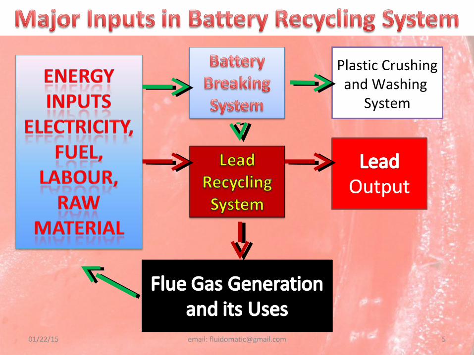
• The recycling process of lead-acid battery starts at the point where old battery is
returned to the Battery Recycler. Lead acid batteries recycling processes are very simple.
The sequential steps are normally the acid removal, separation of plastic case, metallic
lead and paste separation, reduction, refining and casting. Acid, polypropylene and lead
are recovered in the recycling process.
01/22/15 email: [email protected] 2
• Here, in part of world, we have been doing this over a long period. It simple axes the
battery, and lead bearing materials smelt in Mandir Bhatti. Over a period, fuel cost is rising
day by day, labour cost has also been on rising front. Scrap battery rates are also gone
rocketing high due to our own competition and inefficiencies.
• With the progress day by day, we need mechanized system to do the Lead Recycling,
Which should be Environment Friendly, Energy Efficient and Increase our PROFIT too.
01/22/15 email: [email protected] 3
01/22/15 email: [email protected] 6
Plastic Crushing and
Washing System
Plastic Crushing and
Washing System
Battery Parts Segregation and De-Sulphation Plant
Battery Parts Segregation and De-Sulphation Plant
Battery CrusherBattery Crusher
Battery SlicerBattery Slicer
Battery SplitterBattery Splitter
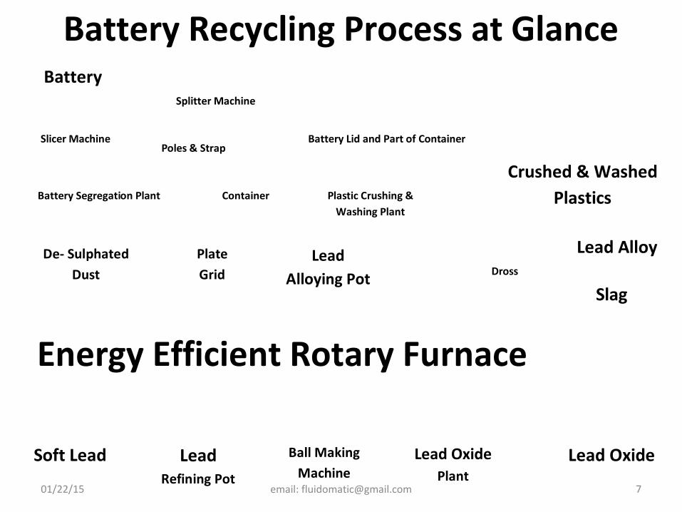
Battery Recycling Process at Glance
01/22/15 email: [email protected] 7
Battery
Slicer Machine
Crushed & Washed Plastics
Plate Grid
Battery Lid and Part of Container
De- Sulphated Dust
Plastic Crushing & Washing Plant
Container Battery Segregation Plant
Splitter Machine
Poles & Strap
Lead Alloying Pot
Lead Alloy Dross
Energy Efficient Rotary Furnace
Slag
Lead
Refining Pot
Soft Lead Ball Making Machine
Lead Oxide Plant
Lead Oxide
01/22/15 email: [email protected] 8
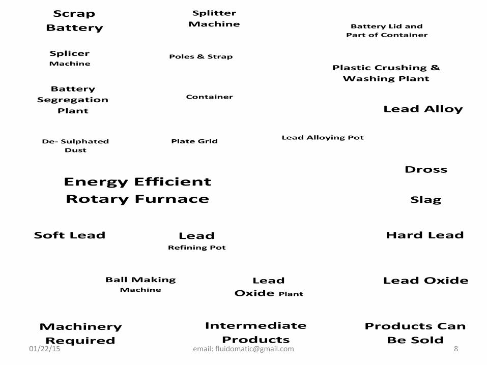
Processes at Glance
Scrap Battery
Splicer Machine
Plate Grid
Battery Lid and Part of Container
De- Sulphated Dust
Plastic Crushing & Washing Plant
Container Battery
Segregation Plant
Splitter Machine
Poles & Strap
Lead Alloying Pot
Lead Alloy
Dross Energy Efficient Rotary Furnace Slag
Lead
Refining Pot
Soft Lead Hard Lead
Ball Making Machine
Lead Oxide Plant
Lead Oxide
Machinery Required
Products Can Be Sold
Intermediate Products
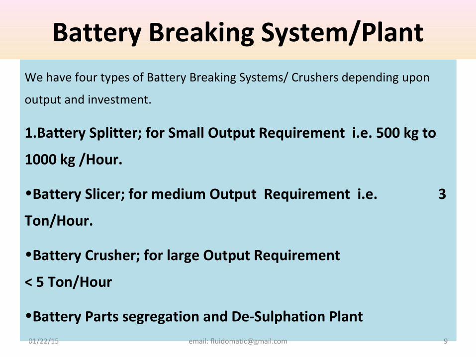
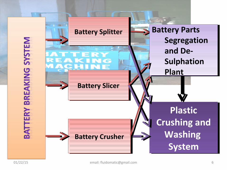
Battery Breaking System/PlantWe have four types of Battery Breaking Systems/ Crushers depending upon
output and investment.
1.Battery Splitter; for Small Output Requirement i.e. 500 kg to
1000 kg /Hour.
•Battery Slicer; for medium Output Requirement i.e. 3
Ton/Hour.
•Battery Crusher; for large Output Requirement
< 5 Ton/Hour
•Battery Parts segregation and De-Sulphation Plant01/22/15 email: [email protected] 9
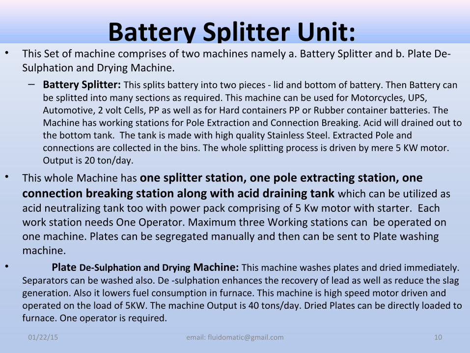
Battery Splitter Unit: • This Set of machine comprises of two machines namely a. Battery Splitter and b. Plate De-
Sulphation and Drying Machine.– Battery Splitter: This splits battery into two pieces - lid and bottom of battery. Then Battery can
be splitted into many sections as required. This machine can be used for Motorcycles, UPS, Automotive, 2 volt Cells, PP as well as for Hard containers PP or Rubber container batteries. The Machine has working stations for Pole Extraction and Connection Breaking. Acid will drained out to the bottom tank. The tank is made with high quality Stainless Steel. Extracted Pole and connections are collected in the bins. The whole splitting process is driven by mere 5 KW motor. Output is 20 ton/day.
• This whole Machine has one splitter station, one pole extracting station, one connection breaking station along with acid draining tank which can be utilized as acid neutralizing tank too with power pack comprising of 5 Kw motor with starter. Each work station needs One Operator. Maximum three Working stations can be operated on one machine. Plates can be segregated manually and then can be sent to Plate washing machine.
• Plate De-Sulphation and Drying Machine: This machine washes plates and dried immediately. Separators can be washed also. De -sulphation enhances the recovery of lead as well as reduce the slag generation. Also it lowers fuel consumption in furnace. This machine is high speed motor driven and operated on the load of 5KW. The machine Output is 40 tons/day. Dried Plates can be directly loaded to furnace. One operator is required.
01/22/15 email: [email protected] 10
01/22/15 email: [email protected] 11
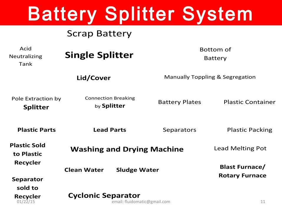
Battery Splitter System
Scrap Battery
Single Splitter
Lid/Cover
Plastic Parts Lead Parts
Connection Breaking
by Splitter
Pole Extraction by
Splitter
Bottom of Battery
Plastic Sold to Plastic Recycler
Blast Furnace/ Rotary Furnace
Washing and Drying Machine
Separator sold to
Recycler
Lead Melting Pot
Acid Neutralizing
Tank
Cyclonic Separator
Sludge Water Clean Water Sludge
Plastic Container Battery Plates
Manually Toppling & Segregation
Separators Plastic Packing
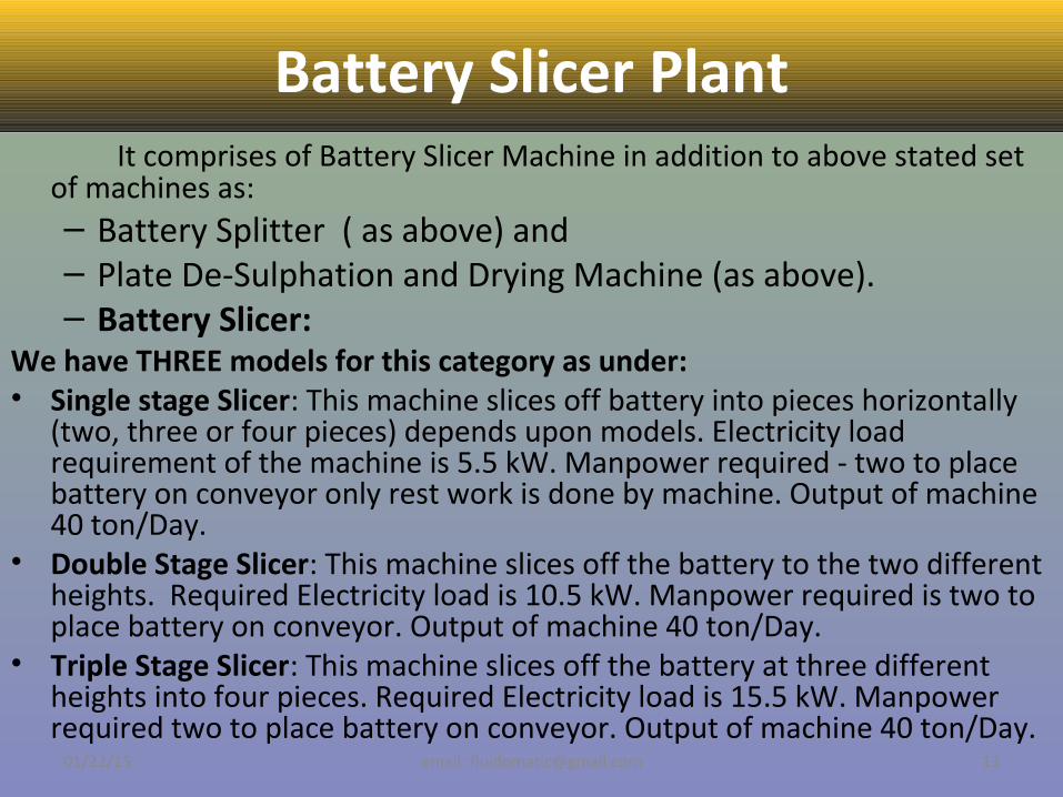
Battery Slicer PlantIt comprises of Battery Slicer Machine in addition to above stated set
of machines as:– Battery Splitter ( as above) and – Plate De-Sulphation and Drying Machine (as above).– Battery Slicer:
We have THREE models for this category as under:• Single stage Slicer: This machine slices off battery into pieces horizontally
(two, three or four pieces) depends upon models. Electricity load requirement of the machine is 5.5 kW. Manpower required - two to place battery on conveyor only rest work is done by machine. Output of machine 40 ton/Day.
• Double Stage Slicer: This machine slices off the battery to the two different heights. Required Electricity load is 10.5 kW. Manpower required is two to place battery on conveyor. Output of machine 40 ton/Day.
• Triple Stage Slicer: This machine slices off the battery at three different heights into four pieces. Required Electricity load is 15.5 kW. Manpower required two to place battery on conveyor. Output of machine 40 ton/Day.
01/22/15 email: [email protected] 13
01/22/15 email: [email protected] 14
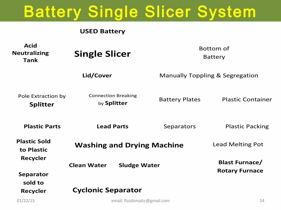
Battery Single Slicer System
USED Battery
Single Slicer
Lid/Cover
Plastic Parts Lead Parts
Connection Breaking
by Splitter
Pole Extraction by
Splitter
Bottom of Battery
Plastic Sold to Plastic Recycler
Blast Furnace/ Rotary Furnace
Washing and Drying Machine
Separator sold to
Recycler
Lead Melting Pot
Acid Neutralizing
Tank
Cyclonic Separator
Sludge Water Clean Water Sludge
Plastic Container Battery Plates
Manually Toppling & Segregation
Separators Plastic Packing
01/22/15 email: [email protected] 15
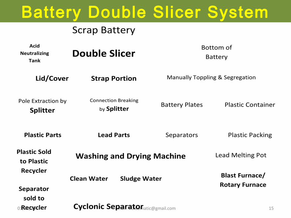
Battery Double Slicer System
Scrap Battery
Double Slicer
Lid/Cover
Plastic Parts Lead Parts
Connection Breaking
by Splitter
Pole Extraction by
Splitter
Bottom of Battery
Plastic Sold to Plastic Recycler
Blast Furnace/ Rotary Furnace
Washing and Drying Machine
Separator sold to
Recycler
Lead Melting Pot
Acid Neutralizing
Tank
Cyclonic Separator
Sludge Water Clean Water Sludge
Plastic Container Battery Plates
Manually Toppling & Segregation
Separators Plastic Packing
Strap Portion
01/22/15 email: [email protected] 16
01/22/15 email: [email protected] 17
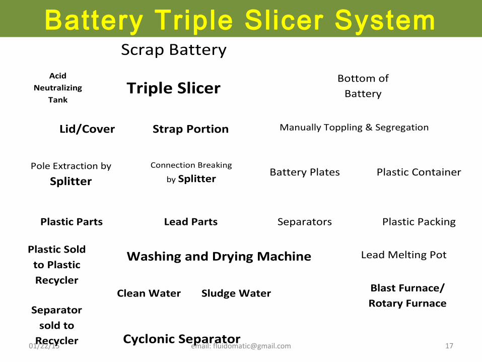
Battery Triple Slicer System
Scrap Battery
Triple Slicer
Strap Portion
Plastic Parts Lead Parts
Connection Breaking
by Splitter
Pole Extraction by
Splitter
Bottom of Battery
Plastic Sold to Plastic Recycler
Blast Furnace/ Rotary Furnace
Washing and Drying Machine
Separator sold to
Recycler
Lead Melting Pot
Acid Neutralizing
Tank
Cyclonic Separator
Sludge Water Clean Water Sludge
Plastic Container Battery Plates
Manually Toppling & Segregation
Separators Plastic Packing
Lid/Cover
01/22/15 email: [email protected] 18
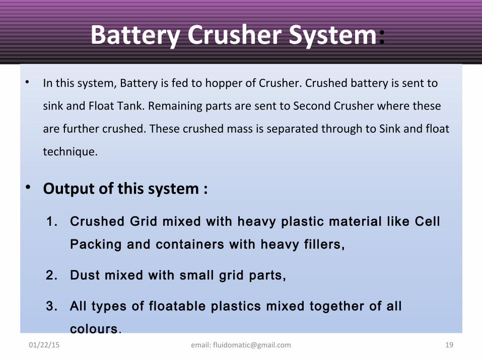
Battery Crusher System:
• In this system, Battery is fed to hopper of Crusher. Crushed battery is sent to
sink and Float Tank. Remaining parts are sent to Second Crusher where these
are further crushed. These crushed mass is separated through to Sink and float
technique.
• Output of this system :
1. Crushed Grid mixed with heavy plastic material l ike Cell
Packing and containers with heavy fi l lers,
2. Dust mixed with small grid parts,
3. All types of f loatable plastics mixed together of all
colours.01/22/15 email: [email protected] 19
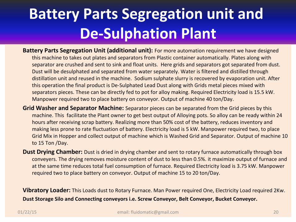
Battery Parts Segregation unit and De-Sulphation Plant
Battery Parts Segregation Unit (additional unit): For more automation requirement we have designed this machine to takes out plates and separators from Plastic container automatically. Plates along with separator are crushed and sent to sink and float units. Here grids and separators got separated from dust. Dust will be desulphated and separated from water separately. Water is filtered and distilled through distillation unit and reused in the machine. Sodium sulphate slurry is recovered by evaporation unit. After this operation the final product is De-Sulphated Lead Dust along with Grids metal pieces mixed with separators pieces. These can be directly fed to pot for alloy making. Required Electricity load is 15.5 kW. Manpower required two to place battery on conveyor. Output of machine 40 ton/Day.
Grid Washer and Separator Machine: Separator pieces can be separated from the Grid pieces by this machine. This facilitate the Plant owner to get best output of Alloying pots. So alloy can be ready within 24 hours after receiving scrap battery. Realizing more than 50% cost of the battery, reduces inventory and making less prone to rate fluctuation of battery. Electricity load is 5 kW. Manpower required two, to place Grid Mix in Hopper and collect output of machine which is Washed Grid and Separator. Output of machine 10 to 15 Ton /Day.
Dust Drying Chamber: Dust is dried in drying chamber and sent to rotary furnace automatically through box conveyers. The drying removes moisture content of dust to less than 0.5%. it maximize output of furnace and at the same time reduces total fuel consumption of furnace. Required Electricity load is 3.75 kW. Manpower required two to place battery on conveyor. Output of machine 15 to 20 ton/Day.
Vibratory Loader: This Loads dust to Rotary Furnace. Man Power required One, Electricity Load required 2Kw.
Dust Storage Silo and Connecting conveyors i.e. Screw Conveyor, Belt Conveyor, Bucket Conveyor.
01/22/15 email: [email protected] 20

Battery Parts Segregation unit and De-Sulphation Plant
01/22/15 email: [email protected] 21
Battery Container with Plate
Battery Segregation
Machine
Battery Plate with Separator
Battery Container
Dust De-Sulphation Plant
De-Sulphated Dust
Plastic Crushing & Washing Plant
Dust Drying Chamber
Moisture free De-Sulphated Dust
Crushed and Washed Plastic
Plate Crushing Machine
Grid and Separator Machine
Grid & Separator Washing Machine
Grid and Pieces of Separator
Blast Furnace/ Rotary Furnace
Alloying Pot
Soft Lead
Lead Alloy
Effluent Treatment
Plant Water Distillation Plant
Sodium Sulphate Lye
01/22/15 email: [email protected] 22
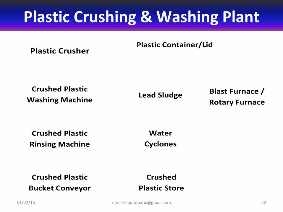
Plastic Container/Lid Plastic Crusher
Crushed Plastic Washing Machine
Crushed Plastic Rinsing Machine
Lead Sludge
Crushed Plastic Bucket Conveyor
Crushed Plastic Store
Blast Furnace / Rotary Furnace
Water Cyclones
Plastic Crushing & Washing Plant
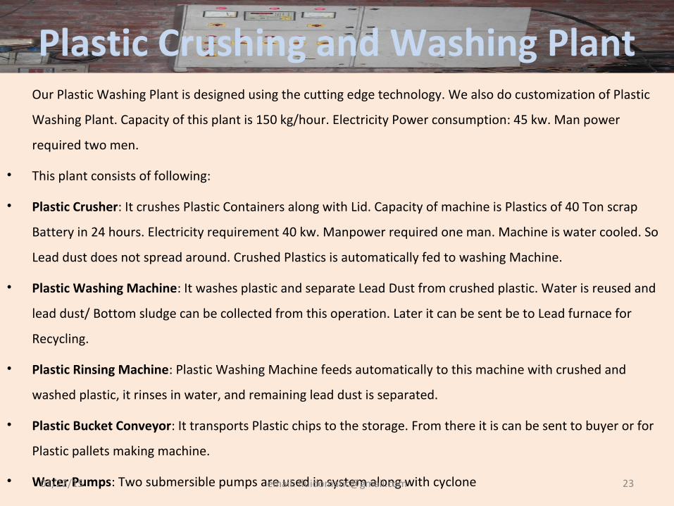
Plastic Crushing and Washing PlantOur Plastic Washing Plant is designed using the cutting edge technology. We also do customization of Plastic
Washing Plant. Capacity of this plant is 150 kg/hour. Electricity Power consumption: 45 kw. Man power
required two men.
• This plant consists of following:
• Plastic Crusher: It crushes Plastic Containers along with Lid. Capacity of machine is Plastics of 40 Ton scrap
Battery in 24 hours. Electricity requirement 40 kw. Manpower required one man. Machine is water cooled. So
Lead dust does not spread around. Crushed Plastics is automatically fed to washing Machine.
• Plastic Washing Machine: It washes plastic and separate Lead Dust from crushed plastic. Water is reused and
lead dust/ Bottom sludge can be collected from this operation. Later it can be sent be to Lead furnace for
Recycling.
• Plastic Rinsing Machine: Plastic Washing Machine feeds automatically to this machine with crushed and
washed plastic, it rinses in water, and remaining lead dust is separated.
• Plastic Bucket Conveyor: It transports Plastic chips to the storage. From there it is can be sent to buyer or for
Plastic pallets making machine.
• Water Pumps: Two submersible pumps are used in system along with cyclone01/22/15 email: [email protected] 23
Lead Recycling PlantWe also required Lead Recycling Plant which should have followings:
(1) To reduce the energy consumption of furnace by improving the heat
transfer mechanism and reducing heat losses and better mechanical stability
and durability with reduce energy consumption and maintenance.
(2) To reduce the emission levels of SPM, SO2, CO2, CO etc. and make furnace
more eco-friendly. The input parameters are optimized to achieve the above
objectives.
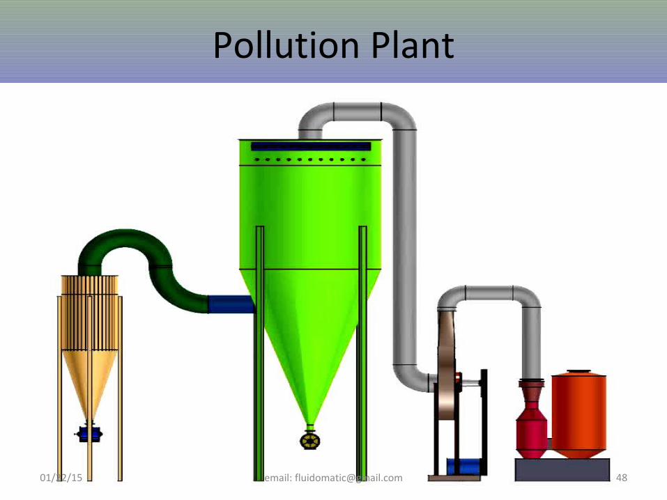
We divide this plant into two sub-systems
• Rotary Plant
• Pollution Control Plant01/22/15 email: [email protected] 24
Identified parameters in the performance of Rotary Furnace to Increase outputs
• Shape of Rotary Furnace
• Sizes of Rotary Furnace as per charge material and its behavior during smelting
• L/D Ratio of Furnace, not just increase diameter of rotary Furnace for more charge which saves lot of material and labour to manufactures of Rotary Furnace. We thought being a foundation of process, it should be as per requirement of process not just a inefficient tool to make profit by machine manufacturers
• Insulation of Rotary furnace
• Drive Mechanism of Rotary Furnace
• Sizes of Tyres i.e. Breadth and Thickness and material and their contact Line to Drive Rollers
• Drive Rollers size and contact line area and variability with load and life complete load of Rotary Furnace, including Shell, Linings, and Charged Material tends to deformation of Tyres and Rollers subsequently early deterioration, due to fatigue, Roller failure/deformation is the result. So Rollers were Redesigned
• Drive Rollers, Chain and ratio to Tyres of Rotary Furnace
• Pillow Blocks were modified to give continuous lubrications to bearings
• Drive Gear Box Life and maintenance cost to be incurred by user
• Ratio and sizes of pulley to maximize the transfer of energy
• Ambient atmosphere of Rotary Furnace
• Mechanical stability of Rotary Furnace01/22/15 email: [email protected] 25
Lead Recycling Plant:
01/22/15 email: [email protected] 26
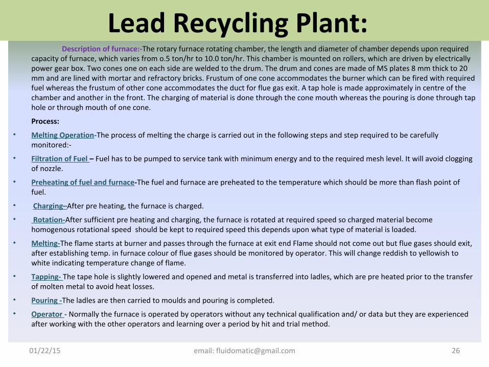
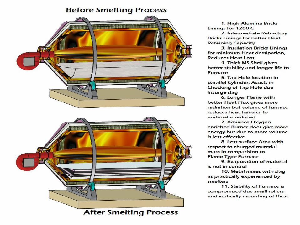
Description of furnace:-The rotary furnace rotating chamber, the length and diameter of chamber depends upon required capacity of furnace, which varies from o.5 ton/hr to 10.0 ton/hr. This chamber is mounted on rollers, which are driven by electrically power gear box. Two cones one on each side are welded to the drum. The drum and cones are made of MS plates 8 mm thick to 20 mm and are lined with mortar and refractory bricks. Frustum of one cone accommodates the burner which can be fired with required fuel whereas the frustum of other cone accommodates the duct for flue gas exit. A tap hole is made approximately in centre of the chamber and another in the front. The charging of material is done through the cone mouth whereas the pouring is done through tap hole or through mouth of one cone.
Process:
• Melting Operation-The process of melting the charge is carried out in the following steps and step required to be carefully monitored:-
• Filtration of Fuel – Fuel has to be pumped to service tank with minimum energy and to the required mesh level. It will avoid clogging of nozzle.
• Preheating of fuel and furnace-The fuel and furnace are preheated to the temperature which should be more than flash point of fuel.
• Charging–After pre heating, the furnace is charged.
• Rotation-After sufficient pre heating and charging, the furnace is rotated at required speed so charged material become homogenous rotational speed should be kept to required speed this depends upon what type of material is loaded.
• Melting-The flame starts at burner and passes through the furnace at exit end Flame should not come out but flue gases should exit, after establishing temp. in furnace colour of flue gases should be monitored by operator. This will change reddish to yellowish to white indicating temperature change of flame.
• Tapping- The tape hole is slightly lowered and opened and metal is transferred into ladles, which are pre heated prior to the transfer of molten metal to avoid heat losses.
• Pouring -The ladles are then carried to moulds and pouring is completed.
• Operator - Normally the furnace is operated by operators without any technical qualification and/ or data but they are experienced after working with the other operators and learning over a period by hit and trial method.
Rotary Furnace for Lead
01/22/15 email: [email protected] 27
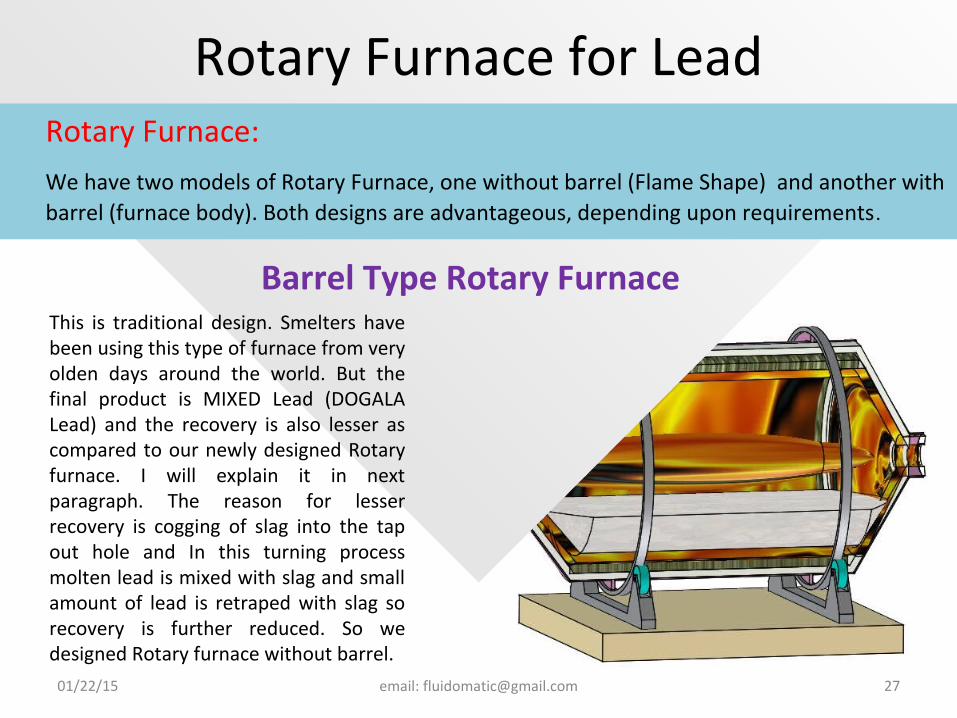
This is traditional design. Smelters have been using this type of furnace from very olden days around the world. But the final product is MIXED Lead (DOGALA Lead) and the recovery is also lesser as compared to our newly designed Rotary furnace. I will explain it in next paragraph. The reason for lesser recovery is cogging of slag into the tap out hole and In this turning process molten lead is mixed with slag and small amount of lead is retraped with slag so recovery is further reduced. So we designed Rotary furnace without barrel.
Rotary Furnace:
We have two models of Rotary Furnace, one without barrel (Flame Shape) and another with barrel (furnace body). Both designs are advantageous, depending upon requirements.
Barrel Type Rotary Furnace
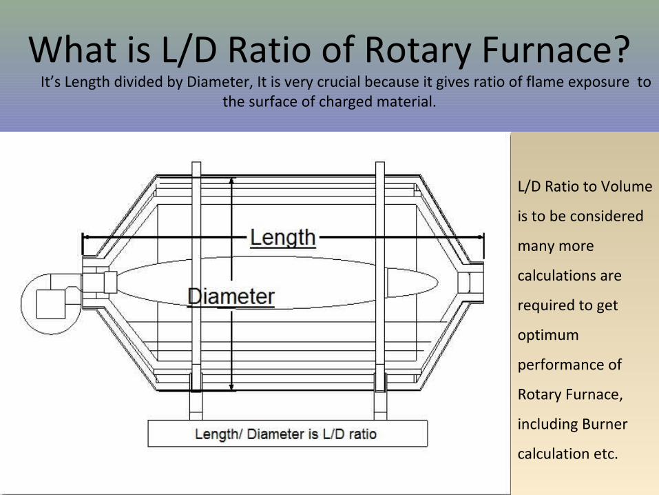
What is L/D Ratio of Rotary Furnace? It’s Length divided by Diameter, It is very crucial because it gives ratio of flame exposure to
the surface of charged material.
01/22/15 email: [email protected] 28
L/D Ratio to Volume
is to be considered
many more
calculations are
required to get
optimum
performance of
Rotary Furnace,
including Burner
calculation etc.
Rotary Furnace for Lead
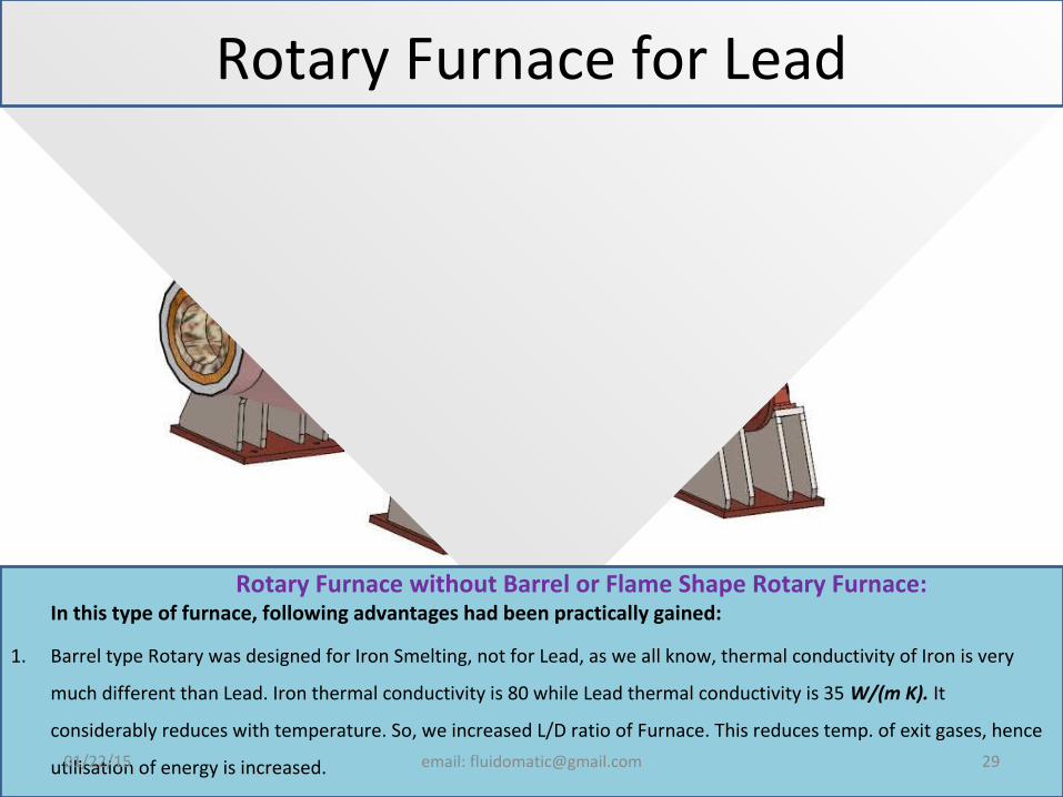
Rotary Furnace without Barrel or Flame Shape Rotary Furnace: In this type of furnace, following advantages had been practically gained:
1. Barrel type Rotary was designed for Iron Smelting, not for Lead, as we all know, thermal conductivity of Iron is very
much different than Lead. Iron thermal conductivity is 80 while Lead thermal conductivity is 35 W/(m K). It
considerably reduces with temperature. So, we increased L/D ratio of Furnace. This reduces temp. of exit gases, hence
utilisation of energy is increased.01/22/15 email: [email protected] 29
01/22/15 email: [email protected] 30
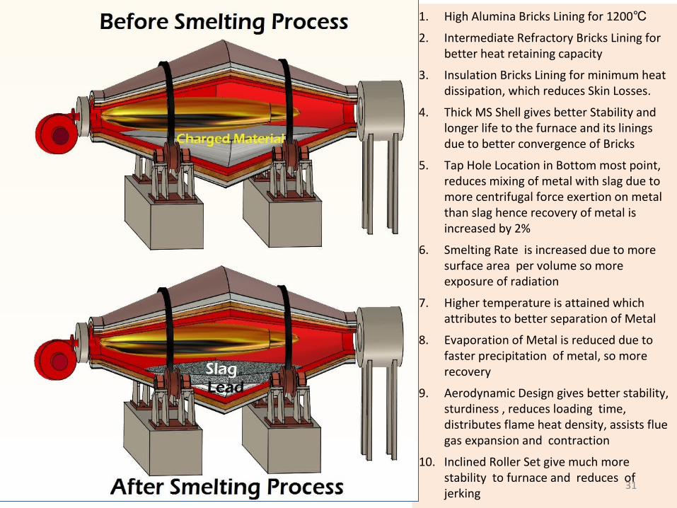
1. High Alumina Bricks Lining for 1200℃2. Intermediate Refractory Bricks Lining for
better heat retaining capacity
3. Insulation Bricks Lining for minimum heat dissipation, which reduces Skin Losses.
4. Thick MS Shell gives better Stability and longer life to the furnace and its linings due to better convergence of Bricks
5. Tap Hole Location in Bottom most point, reduces mixing of metal with slag due to more centrifugal force exertion on metal than slag hence recovery of metal is increased by 2%
6. Smelting Rate is increased due to more surface area per volume so more exposure of radiation
7. Higher temperature is attained which attributes to better separation of Metal
8. Evaporation of Metal is reduced due to faster precipitation of metal, so more recovery
9. Aerodynamic Design gives better stability, sturdiness , reduces loading time, distributes flame heat density, assists flue gas expansion and contraction
10. Inclined Roller Set give much more stability to furnace and reduces of jerking
01/22/15 email: [email protected] 31
Advantages of Flame Type Rotary Furnace
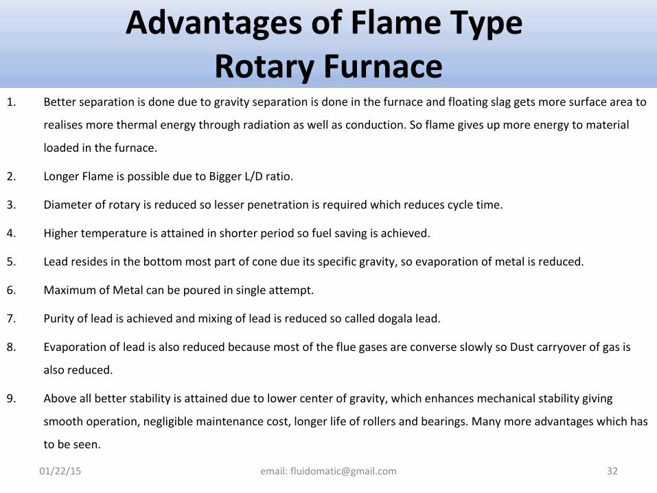
1. Better separation is done due to gravity separation is done in the furnace and floating slag gets more surface area to
realises more thermal energy through radiation as well as conduction. So flame gives up more energy to material
loaded in the furnace.
2. Longer Flame is possible due to Bigger L/D ratio.
3. Diameter of rotary is reduced so lesser penetration is required which reduces cycle time.
4. Higher temperature is attained in shorter period so fuel saving is achieved.
5. Lead resides in the bottom most part of cone due its specific gravity, so evaporation of metal is reduced.
6. Maximum of Metal can be poured in single attempt.
7. Purity of lead is achieved and mixing of lead is reduced so called dogala lead.
8. Evaporation of lead is also reduced because most of the flue gases are converse slowly so Dust carryover of gas is
also reduced.
9. Above all better stability is attained due to lower center of gravity, which enhances mechanical stability giving
smooth operation, negligible maintenance cost, longer life of rollers and bearings. Many more advantages which has
to be seen.
01/22/15 email: [email protected] 32
01/22/15 email: [email protected] 33
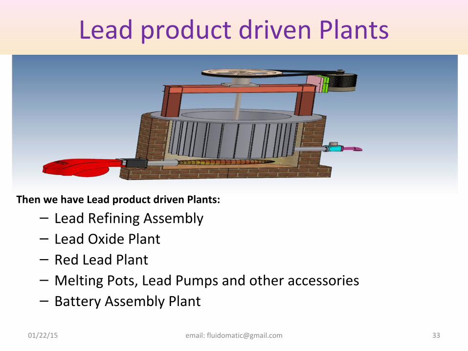
Then we have Lead product driven Plants:
– Lead Refining Assembly– Lead Oxide Plant– Red Lead Plant– Melting Pots, Lead Pumps and other accessories– Battery Assembly Plant
Lead product driven Plants
01/22/15 email: [email protected] 34
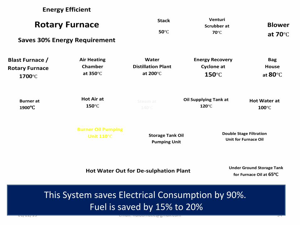
Double Stage Filtration Unit for Furnace Oil
Stack
50℃
Air Heating Chamber at 350℃
Blast Furnace / Rotary Furnace
1700℃
Energy Efficient
Rotary Furnace
Saves 30% Energy Requirement
Water Distillation Plant
at 200℃
Venturi Scrubber at
70℃
Blower at 70℃
Bag House
at 80℃
Energy Recovery Cyclone at
150℃
Burner Oil Pumping Unit 110℃
Under Ground Storage Tank
for Furnace Oil at 65℃ Hot Water Out for De-sulphation Plant
Storage Tank Oil Pumping Unit
Burner at
1900℃
Hot Air at 150℃
Steam at 140℃
Hot Water at 100℃
Oil Supplying Tank at 120℃
This System saves Electrical Consumption by 90%. Fuel is saved by 15% to 20%
Energy Saving Burner System: What is Burner?
• Burner is a device which mixes fuel into a required ratio so it burn and gives out final product as heat and gases. Now, burning is done in non adjustable manner. Fuel flow and Oxygen/Air flow with required pressure is achieved with adjustable controls of both inputs.
What is Burning?
• Burning is uncontrolled process, where any of fuel oxidizes in air or in oxygen. It gives out heat, light and flue gases. As hydrogen in oxygen atmosphere oxidizes and water droplets is formed. Carbon oxidizes with oxygen and carbon dioxide or carbon monoxide is formed. There can be mixture of both the gases as output gases or any of gas can be formed, but Carbon Monoxide gives out lesser heat energy whereas carbon dioxide gives out more energy.
What is Combustion?
• Fuel has to be combusted. Here, it converts chemical energy into heat energy in a sensible and efficient manner; it is required to be combusted. So To ensure complete combustion of the fuel used, combustion chambers are supplied with required air. But it is not possible to supply exact amount of air so we supply excess air. Excess air increases the amount of oxygen and the probability of complete combustion of fuel. When fuel and oxygen in the air are in perfectly balance, the combustion is said to be stoichiometric combustion. Output heat has to convert to sensible heat and in a controlled manner. 01/22/15 email: [email protected] 36
How Efficient Combustion is achieved?
• Oxidation reaction of fuel takes place rapidly. It depends upon surface area
of fuel and contact area of that surface with oxygen, present in air which is
21% approx., and pressure of air. Heat is delivered to the material present
in the chamber through Radiation, Convection and Conduction.
• But flue gas being output of reaction of Fuel and Oxygen, flue gases acts as
medium of transportation of heat too but at the same time it has to be
removed immediately so that next process can takes place. So while
leaving, it also heats up during reaction and takes away a large amount of
heat with it. This is called flue gases losses, amounts to 50% approx.
01/22/15 email: [email protected] 37
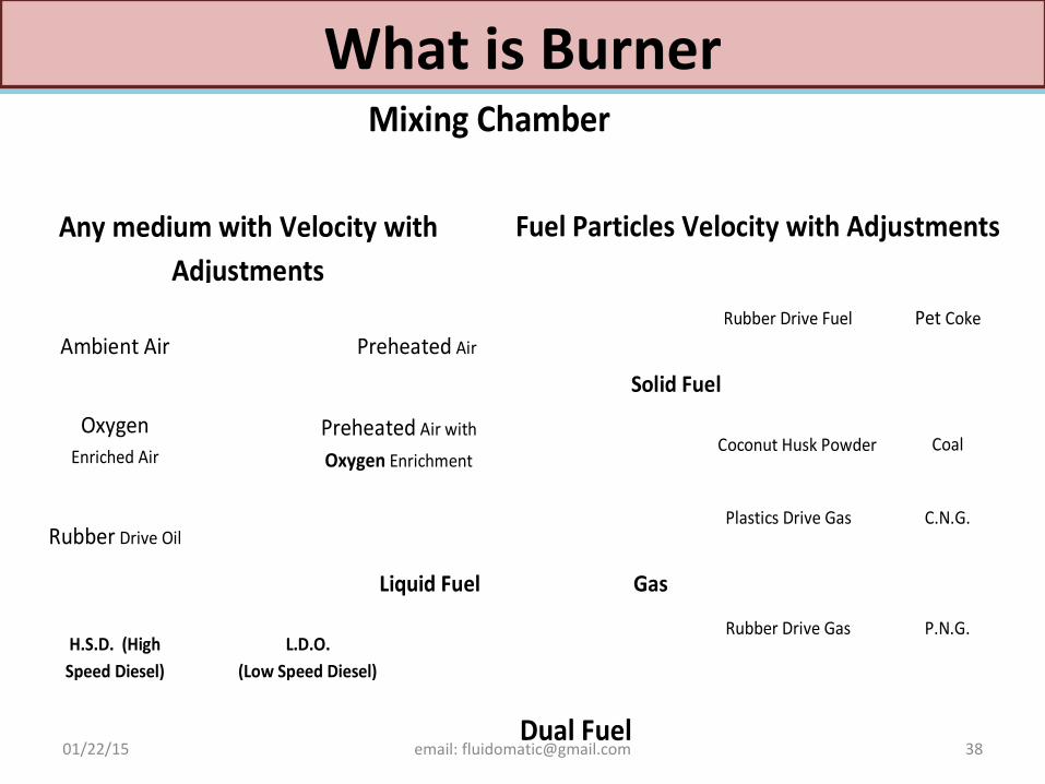
What is BurnerWhat is Burner
01/22/15 email: [email protected] 38
Mixing Chamber
Preheated Air
Preheated Air with
Oxygen Enrichment
Any medium with Velocity with Adjustments
Ambient Air
Oxygen
Enriched Air
Fuel Particles Velocity with Adjustments
H.S.D. (High Speed Diesel)
L.D.O. (Low Speed Diesel)
Liquid Fuel
Rubber Drive Oil Furnace Oil
Rubber Drive Fuel
Solid Fuel
Coal
Pet Coke
Coconut Husk Powder
Plastics Drive Gas
Rubber Drive Gas
Gas
P.N.G.
C.N.G.
Dual Fuel
01/22/15 email: [email protected] 40
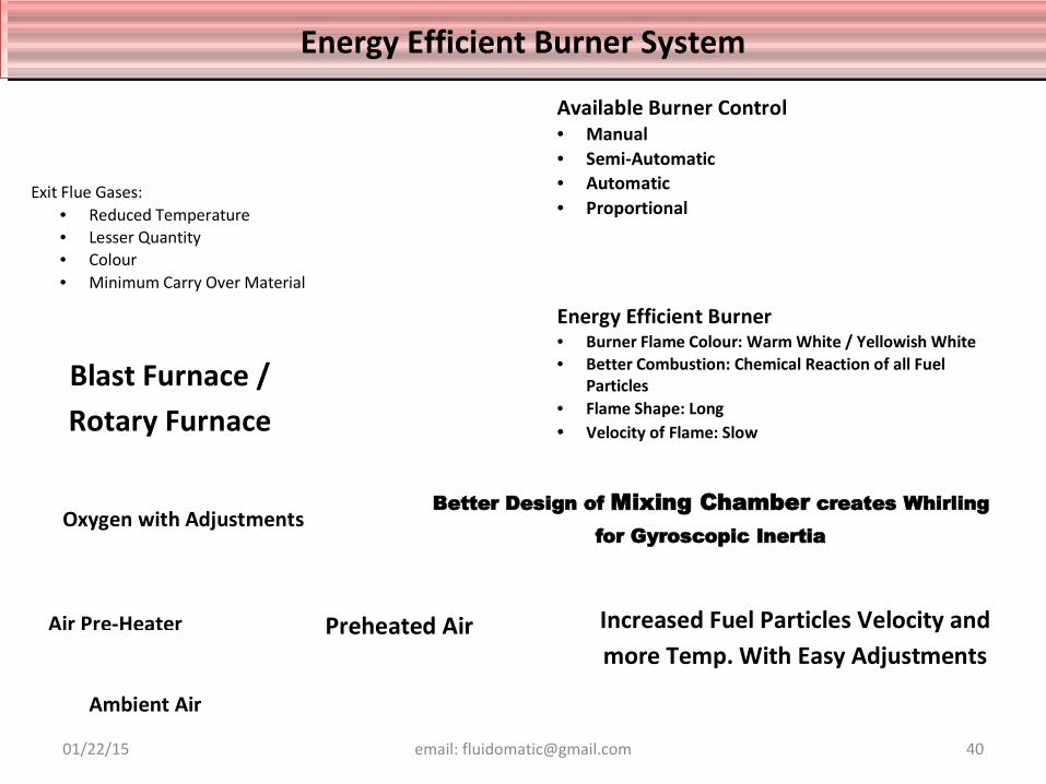
Energy Efficient Burner • Burner Flame Colour: Warm White / Yellowish White • Better Combustion: Chemical Reaction of all Fuel
Particles • Flame Shape: Long • Velocity of Flame: Slow
Blast Furnace / Rotary Furnace
Exit Flue Gases: • Reduced Temperature • Lesser Quantity • Colour • Minimum Carry Over Material
Available Burner Control • Manual • Semi-Automatic • Automatic • Proportional
Increased Fuel Particles Velocity and more Temp. With Easy Adjustments
Better Design of Mixing Chamber creates Whirling for Gyroscopic Inertia
Air Pre-Heater
Oxygen with Adjustments
Ambient Air
Preheated Air
Energy Efficient Burner SystemEnergy Efficient Burner System
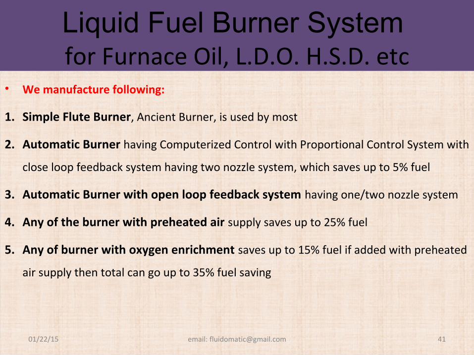
Liquid Fuel Burner System for Furnace Oil, L.D.O. H.S.D. etc
• We manufacture following:
1. Simple Flute Burner, Ancient Burner, is used by most
2. Automatic Burner having Computerized Control with Proportional Control System with
close loop feedback system having two nozzle system, which saves up to 5% fuel
3. Automatic Burner with open loop feedback system having one/two nozzle system
4. Any of the burner with preheated air supply saves up to 25% fuel
5. Any of burner with oxygen enrichment saves up to 15% fuel if added with preheated
air supply then total can go up to 35% fuel saving
01/22/15 email: [email protected] 41
Solid Fuel Burners• Solid Fuel Burners with/without preheated air supply and/or oxygen
enrichment system.
• Coal Burner
• Pet Coke Burner
• RDF Burner
• Charcoal Burner
• All these burners either with Oxygen enriched air or preheated air or with both
will save up to 35% and 2% more recovery of Lead.
01/22/15 email: [email protected] 42
Gas Fuel Burners• Gas Fuel Burners with/without preheated air supply and/or oxygen enrichment system.
• Pressurised Natural Gas shortly known as P.N.G. or PNG
• Compressed Natural Gas shortly known as C.N.G. or CNG
01/22/15 email: [email protected] 43
Duel Fuel Burners i.e. abovementioned any of solid fuel with gas or liquid fuel so in case any
of the fuel is available, system is ON even for preheating furnace. This burner is most
advantageous. It gives edge during fuel prices fluctuation and readiness.
• All the burners with preprogrammed PLC system are available with us.
Duel Fuel Burners
How to maximize temperature of flame and gain maximum heat transfer?
Values of the predicted adiabatic flame temperature for hydrocarbon fuels are affected by the following factors:
1. The calorific value (and chemical composition) of the fuel
2. The air-to-fuel ratio at which combustion takes place
3. The initial temperature (preheat) of the air and fuel
• How flame transfers maximum heat energy to furnace and charge material ?Transfer of heat is depends upon following:
1) Difference of Temp.
2) Area of exposure.
3) Transfer rate of medium
4) Heat coefficient of material
5) Pressure in furnace
6) After heat transfer, product of combustion has to be replaced for new reaction.01/22/15 email: [email protected] 44
Journey of flue gas and release of its energy
Once Flue Gases have released their sufficient energy to the furnace, it has to be released to
atmosphere in environmentally friendly way and after getting maximum energy as input.
We release these gases.
01/22/15 email: [email protected] 45
What are the ingredients are in flue gases? • Flue Gases contain Heat energy with SPM, SO2, CO2, CO, NOx etc.
• SPM is the reactant of charged material with gases and evaporated particles
of the same.
• SO2 is reactant of sulphur present Charged material.
• CO2, CO are product of reactant of carbon with oxygen.
• Nox is products of reactant of nitrogen with oxygen.
Equipments used to guide flue gases to Stack so these can be released to atmosphere in eco-friendly way.
01/22/15 email: [email protected] 46
End BlockIt direct flue gases to settling chamber. It is round or square shape
which houses refractory bricks to minimize heat dissipation in it. It
should be easily slide able so having access for cleaning in case of
molten material settling on the way to settling chamber. It can be
mechanically /electrically powered for shifting.
Settling ChamberIt is a chamber made with Red bricks or Refractory bricks to pass flue gases which give stability of temperature and reduces radiation losses of furnace. It slow down velocity of flue gases so larger particles settles due to gravity. Its efficiency depends upon residence time with lowering velocity of flue gas stream. It lowers velocity of flue gases, this helps to drop larger particles (SPM) with the help of gravitational force, which gives residence time to flue gas more residence time, more droppage of SPM, lowers velocity, lowers volume of flue gases.Advantages of Settling Chamber:
• Low capital Cost• No visible energy cost but very low energy cost in term of loading of I/D Fan.• No moving Parts, practically very low maintenance cost• Excellent reliability• Low pressure drop• Provide cooling of Flue gases• Temperature Limitation is dependent on type of construction material
Area of improvement in Designing of Settling Chamber:• Base area and height of chamber depends upon what temperature drop, SPM drop required
with minimum pressure drop• Heat Recovery equipment can be installed or connected to it• It can have vertical partition to drop more SPM so load on other equipment can be reduced.• There are two models in this Settling chamber or gravity settling chamber.• If Temperature is dropped rapidly, it will also increase its efficiency01/22/15 email: [email protected] 47
Cyclone• It a equipment to separate any particle suspended in the stream of fluid it may be water or gases with
any filter. It does this by exerting centrifugal force with the help of pressure difference. Size of particle
depends upon its design parameter whether it is dust particle or liquid mist. The polluted gas stream is
forced into a vortex.
Principle of operation:
• The motion of the gas exerts a centrifugal force on the particles, and this force depends upon size and
mass of particles. There particles go to outer periphery and get deposited on the inner surface of the
cyclones, Here these are dropped due to gravitational force. The movement of particles is in spiral path
so once stream of fluid leaves and proceeds towards outlet through the vortex cleaner stream of fluid
proceeds towards outlet and heavy particles remain at the bottom and ultimately fall out.
• Efficiency Improvement Depends:
• Efficiency of Cyclone depends upon Density of Fluid, Particle sizes, Fluid flow Rate, Fluid Viscosity, Dust
Loading. Efficiency of cyclone increases with increases in Fluid flow rate, Particle sizes, Density and
decrease in fluid viscosity.
• We have designed three types of cyclones:
01/22/15 email: [email protected] 49
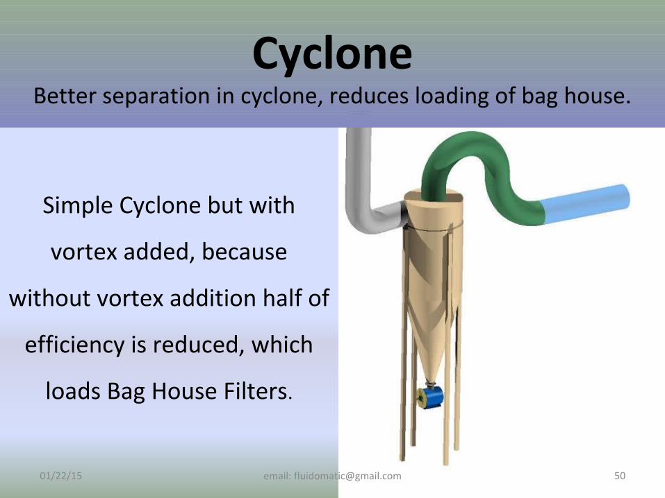
Simple Cyclone but with
vortex added, because
without vortex addition half of
efficiency is reduced, which
loads Bag House Filters.
01/22/15 email: [email protected] 50
CycloneBetter separation in cyclone, reduces loading of bag house.
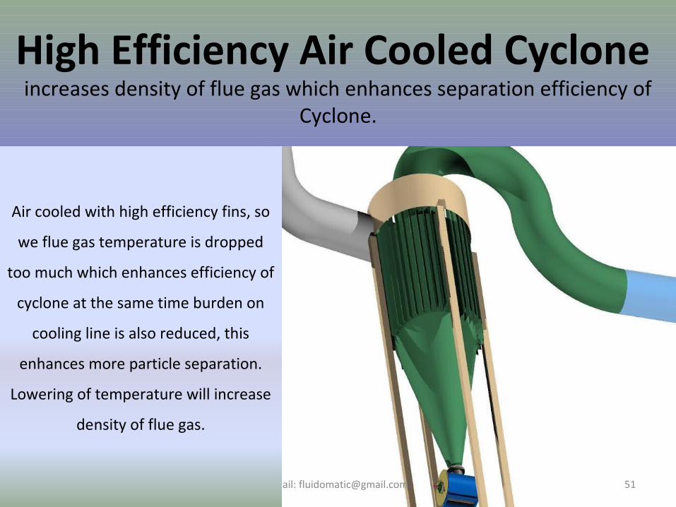
High Efficiency Air Cooled Cyclone increases density of flue gas which enhances separation efficiency of
Cyclone.
01/22/15 email: [email protected] 51
Air cooled with high efficiency fins, so
we flue gas temperature is dropped
too much which enhances efficiency of
cyclone at the same time burden on
cooling line is also reduced, this
enhances more particle separation.
Lowering of temperature will increase
density of flue gas.
01/22/15 email: [email protected] 52
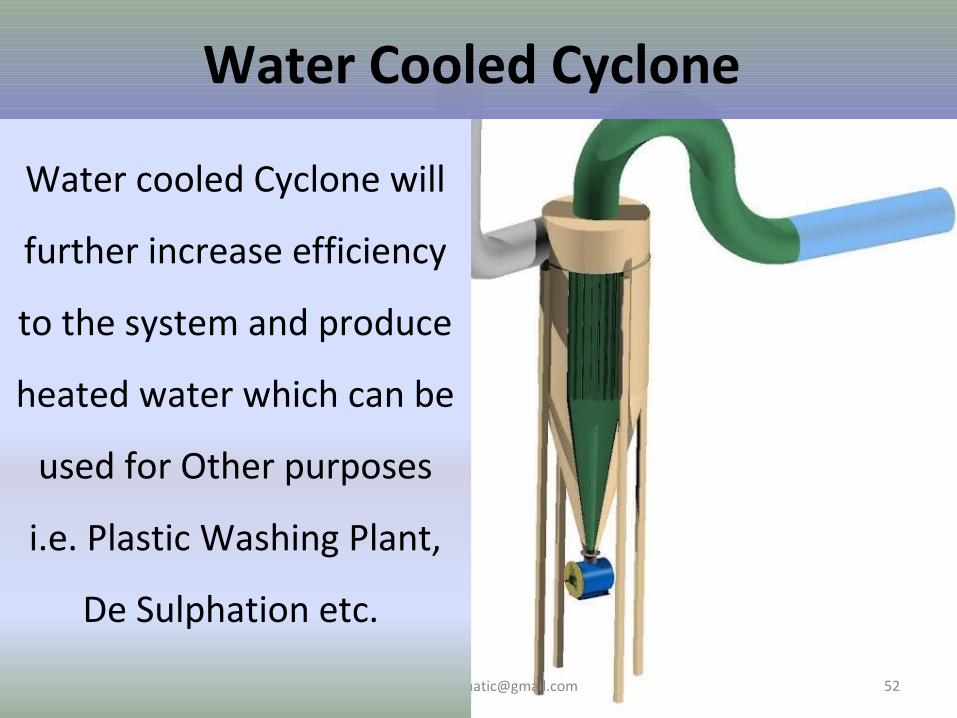
Water cooled Cyclone will
further increase efficiency
to the system and produce
heated water which can be
used for Other purposes
i.e. Plastic Washing Plant,
De Sulphation etc.
Water Cooled Cyclone
Bag House or Bag Filter House • Bag House or Bag Filter House is equipment which houses filter bags. It has two
compartments separated by filter bags in such a manner that any of air stream passes
through one compartment to another, that has to pass through Fabric Bag. One
compartment is connected to in stream of flue gases and another to the inlet of Blower.
Energy on the particles is exerted by pressure difference of both the compartments and flow
of gases is created by Blower. Pressure drop in Bag House will depend upon Dust particle
accumulated on the surface of bag fabric and no. of we have Bag House in cyclonic shape as
well Rectangular Shape. Cyclonic Shape gives added advantage of filtration through fabric
filters as well cyclonic separation. It reduces loading on Fabric Filter Bags.
• Type of fabric depends upon particle and temperature. The filters retain particles larger than
the mesh size. Air and most of the smaller particles flow through. Some of the smaller
particles are retained due to interception and diffusion. The retained particles cause a
reduction in the mesh size. The primary collection is on the layer of previously deposited
particles. Pressure drop will depends upon no. of bags. Higher no. of bags higher the
filtration area, so lesser pressure drop is exerted.01/22/15 email: [email protected] 53
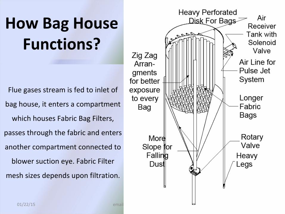
Flue gases stream is fed to inlet of
bag house, it enters a compartment
which houses Fabric Bag Filters,
passes through the fabric and enters
another compartment connected to
blower suction eye. Fabric Filter
mesh sizes depends upon filtration.
01/22/15 email: [email protected] 54
How Bag House Functions?
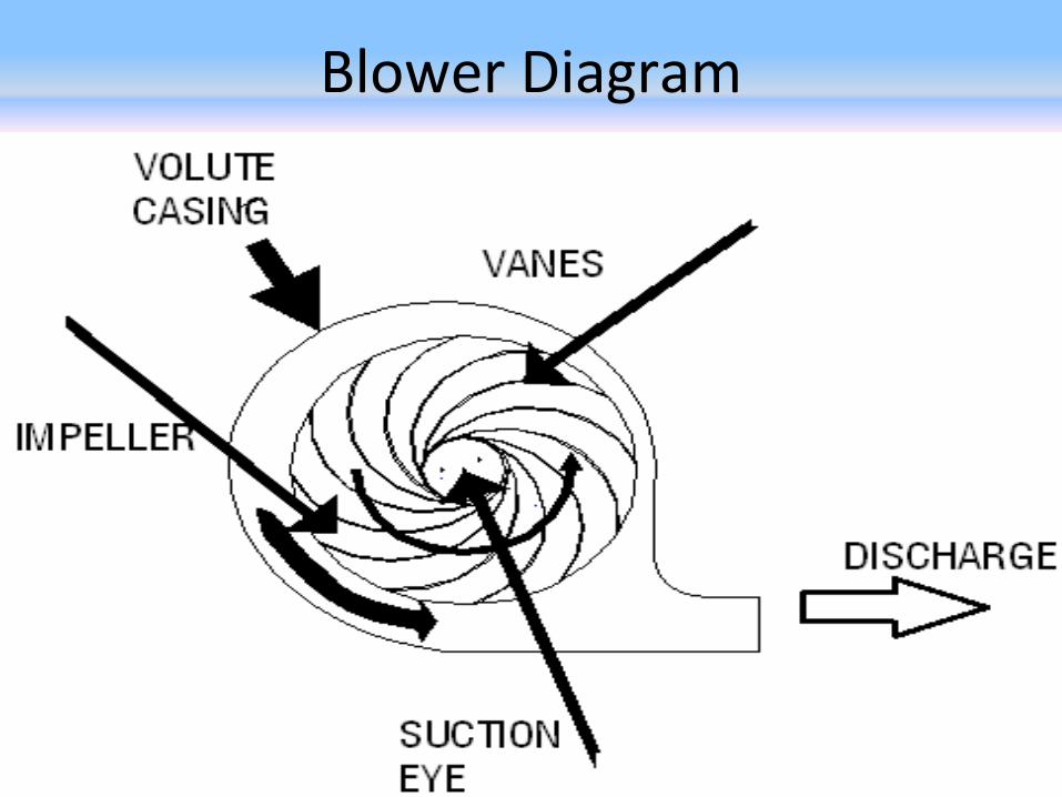
Fan and BlowerWhat is difference between Fan and Blower?
• Fan has lower specific ratio in term of pressure (mm Wg) but more flow in term of CFM (cubic foot per minute volume) whereas blower has more specific ratio (mm in Water Gauge) but lesser flow in volume (CFM).
What is difference between I/D fan/blower and F/D fan/blower?
01/22/15 email: [email protected] 56
I/D fan/blower sucks air/gas flow whereas F/D fan/blower forces air/gases.
I/D (Induced Draft) Blower: We have to flow air/ flue gases out of Furnace. So some force is required to
move flue gases through the Settling Chamber, Cyclones, Cooling Lines and bag house. This force is
induced by the Blower on flue gases.
Blowers/ Fans exert a pressure to move air (or gases) against a resistance caused by ducts, dampers, or
other system components
in a gas flow system. The fan/blower rotor/impeller receives torque from a rotating shaft of electric
motor or some other driver. Impeller of fan/blower forces gases through the system.
F/D Blower: When air/gas has to be forced to the system then force has to be exerted on air/gas by
rotating impeller in the volute casing. It is shown in diagram.
How to get better efficiency out of Blowers?
As RPM is increased for more flow, power is increased cubically whereas if diameter is
increased then power is only doubled, so bigger size of blower is more useful at lesser RPM
than smaller size blower at more RPM.
Blowers are sold on H.P. Load so it is better for blower manufacturer to give smaller blower
at higher RPM whereas process requirement is bigger size of blower at lesser RPM with
properly designed impeller and volute casing with minimal noise and drag.
Basic requirement for both types of blower are following:
1. Air Volume, this depends upon fuel consumption in the system and required pressure
in the furnace.
2. Drive type, Direct driven / indirect driven / Direct coupled.
3. Operating Temperature.
4. Blower RPM will make less/ more Motor H.P.
5. Construction material, depends upon flue gas01/22/15 email: [email protected] 58
Wet Scrubber• This equipment is used to remove SPM of finer sizes those have passed through Fabric Filters by
spraying fine liquid droplets. This equipment can also treat flue gas stream for its chemically contamination by adding some chemical in liquid so chemically charged liquid can react with the stream gases and making some other compound which can also precipitate with SPM. It reduces toxicity of stream within permissible limit. Liquid is subsequently removed for treatment.
• Advantages of Wet Scrubbers
– Wet Scrubbers can handle incoming streams at high temperature, thus removing the need for temperature control equipment.
– Wet scrubbers can handle high particle loading.
– Loading fluctuations do not affect the removal efficiency.
– They can handle explosive gases with little risk.
– Gas adsorption and dust collection are handled in one unit.
– Corrosive gases and dusts are neutralized.
• Disadvantages of Wet Scrubbers
– High potential for corrosive problems
– Effluent scrubbing liquid poses a water pollution problem.
– It loads flue gases with fine liquid droplets which corrodes Chimney/Stack.
01/22/15 email: [email protected] 59
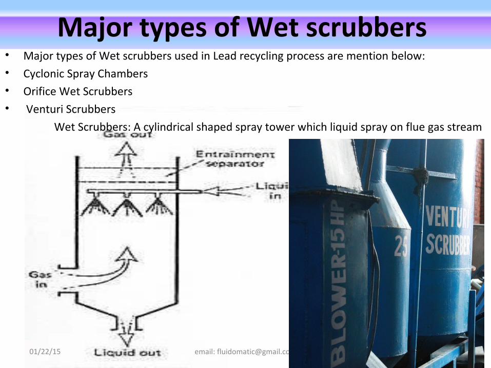
Major types of Wet scrubbers • Major types of Wet scrubbers used in Lead recycling process are mention below:• Cyclonic Spray Chambers• Orifice Wet Scrubbers• Venturi Scrubbers
Wet Scrubbers: A cylindrical shaped spray tower which liquid spray on flue gas stream
01/22/15 email: [email protected] 60
Stack
• Stack (Chimney): Stack is a vertical pipe, which guides flow of Flue gase to upper layer. Required Height is as per CPCB.
• Stack has foundation strong enough to support the structure in case of wind flow, stress created by nature including minor tremors, cyclones etc.
• It has higher ambient pressure at the bottom and lower pressure at
top which creates draft inside the stack, this assist to flow flue gases to the atmosphere.
01/22/15 email: [email protected] 61
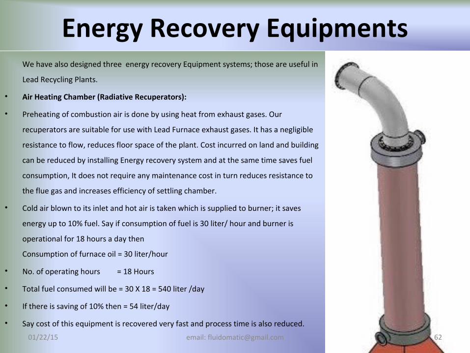
Energy Recovery EquipmentsWe have also designed three energy recovery Equipment systems; those are useful in
Lead Recycling Plants.
• Air Heating Chamber (Radiative Recuperators):
• Preheating of combustion air is done by using heat from exhaust gases. Our
recuperators are suitable for use with Lead Furnace exhaust gases. It has a negligible
resistance to flow, reduces floor space of the plant. Cost incurred on land and building
can be reduced by installing Energy recovery system and at the same time saves fuel
consumption, It does not require any maintenance cost in turn reduces resistance to
the flue gas and increases efficiency of settling chamber.
• Cold air blown to its inlet and hot air is taken which is supplied to burner; it saves
energy up to 10% fuel. Say if consumption of fuel is 30 liter/ hour and burner is
operational for 18 hours a day then
Consumption of furnace oil = 30 liter/hour
• No. of operating hours = 18 Hours
• Total fuel consumed will be = 30 X 18 = 540 liter /day
• If there is saving of 10% then = 54 liter/day
• Say cost of this equipment is recovered very fast and process time is also reduced.
01/22/15 email: [email protected] 62
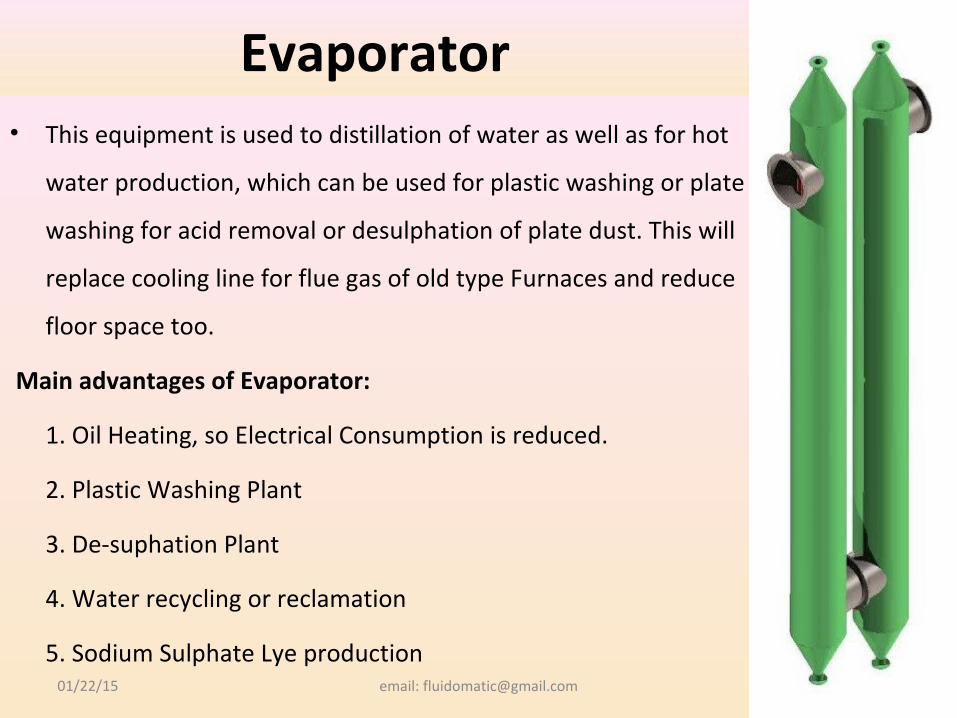
Evaporator• This equipment is used to distillation of water as well as for hot
water production, which can be used for plastic washing or plate
washing for acid removal or desulphation of plate dust. This will
replace cooling line for flue gas of old type Furnaces and reduce
floor space too.
Main advantages of Evaporator:
1. Oil Heating, so Electrical Consumption is reduced.
2. Plastic Washing Plant
3. De-suphation Plant
4. Water recycling or reclamation
5. Sodium Sulphate Lye production01/22/15 email: [email protected] 63
01/22/15 email: [email protected] 64
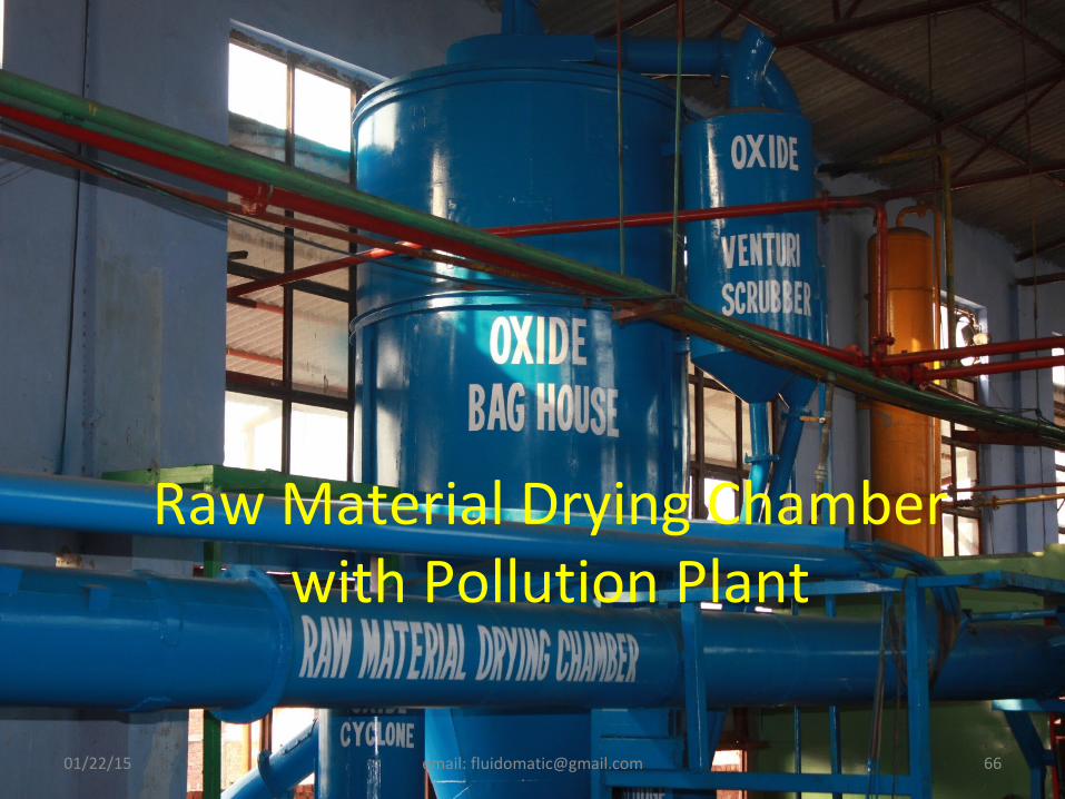
Raw Material Drying Chamber• Raw material to be charged to Rotary Furnace, in our case it is Battery Plates or
Plate Dust, if it is preheated to the temperature, then water will vaporized so heat
required to vaporized will be reduce, there it will be vapourised to super heated
steam in comparison to ambient vapour. Super heated steam will require more
energy to ambient vapour. At the same it removes sulphate vapour, and transform
to Lead Oxide, reducing charged weight to furnace. This reduces sulphur dioxide
emission in furnace.
• It will lower smelting temperature of charged material. Slag fluidization will be
better which gives more recovery of lead. It also reduce Lead content in slag.
01/22/15 email: [email protected] 65
01/22/15 email: [email protected] 67
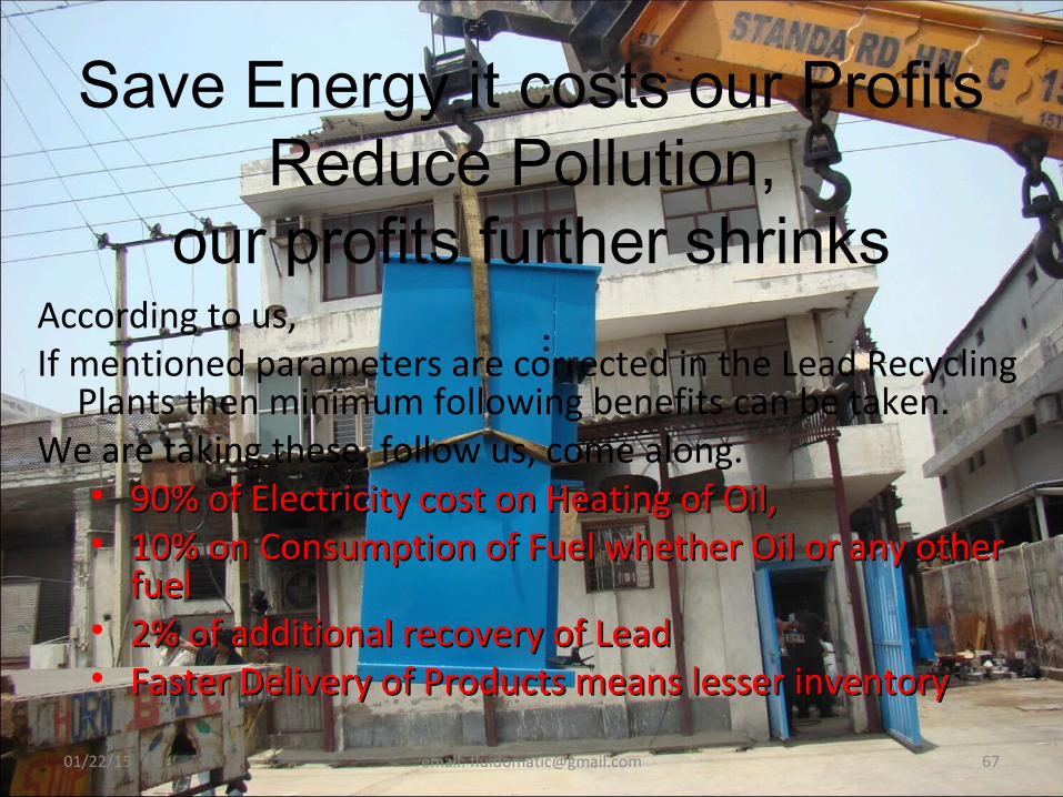
Save Energy it costs our ProfitsReduce Pollution,
our profits further shrinksAccording to us, If mentioned parameters are corrected in the Lead Recycling
Plants then minimum following benefits can be taken. We are taking these, follow us, come along.• 90% of Electricity cost on Heating of Oil,90% of Electricity cost on Heating of Oil,• 10% on Consumption of Fuel whether Oil or any other 10% on Consumption of Fuel whether Oil or any other
fuelfuel• 2% of additional recovery of Lead2% of additional recovery of Lead• Faster Delivery of Products means lesser inventoryFaster Delivery of Products means lesser inventory

01/22/15 email: [email protected] 68
You may contact us for any
assistance/consultation/product at
Fluid-O-Maticat B-24, Sector-60, Noida
or at our Website: www.fluidomatic.netor by email at [email protected]