tr 101 130 - v01.01.01 - electromagnetic compatibility and ... · f-06921 sophia antipolis cedex...
TRANSCRIPT
European Telecommunications Standards Institute
TR 101 130 V1.1.1 (1997-11)Technical Report
Electromagnetic compatibilityand Radio spectrum Matters (ERM);
Study of the feasibility for standardizingSelf-organizing Time Division Multiple Access (STDMA)
system requirements

TR 101 130 V1.1.1 (1997-11)2
ReferenceDTR/ERM-RP05-008 (ago00ics.PDF)
KeywordsAeronautical, mobile
ETSI Secretariat
Postal addressF-06921 Sophia Antipolis Cedex - FRANCE
Office address650 Route des Lucioles - Sophia Antipolis
Valbonne - FRANCETel.: +33 4 92 94 42 00 Fax: +33 4 93 65 47 16
Siret N° 348 623 562 00017 - NAF 742 CAssociation à but non lucratif enregistrée à laSous-Préfecture de Grasse (06) N° 7803/88
X.400c= fr; a=atlas; p=etsi; s=secretariat
[email protected]://www.etsi.fr
Copyright Notification
No part may be reproduced except as authorized by written permission.The copyright and the foregoing restriction extend to reproduction in all media.
© European Telecommunications Standards Institute 1997.All rights reserved.
TR 101 130 V1.1.1 (1997-11)3
Contents
Intellectual Property Rights................................................................................................................................6
Foreword ............................................................................................................................................................6
1 Scope........................................................................................................................................................71.1 Background ........................................................................................................................................................71.2 Organization of the report ..................................................................................................................................7
2 References................................................................................................................................................8
3 Symbols and abbreviations ......................................................................................................................93.1 Symbols..............................................................................................................................................................93.2 Abbreviations .....................................................................................................................................................9
4 Summary of STDMA.............................................................................................................................104.1 Introduction ......................................................................................................................................................104.2 System requirements.........................................................................................................................................104.3 Candidate data link technologies......................................................................................................................134.4 Key features of STDMA ..................................................................................................................................134.5 STDMA system concept...................................................................................................................................14
5 Approach to the review of STDMA.......................................................................................................15
6 Results of the review of STDMA ..........................................................................................................156.1 Introduction ......................................................................................................................................................156.2 The need for STDMA ......................................................................................................................................166.2.1 Market need ................................................................................................................................................166.2.2 Technical need............................................................................................................................................166.2.3 Current progress towards standardization...................................................................................................176.2.4 Ongoing trials projects................................................................................................................................186.2.5 Summary.....................................................................................................................................................186.3 Procedural issues ..............................................................................................................................................196.4 Standardization issues ......................................................................................................................................206.4.1 Introduction ................................................................................................................................................206.4.2 The need for a clear system concept ...........................................................................................................206.4.2.1 The need for clear interfaces .................................................................................................................206.4.2.2 Clear boundaries for the system ............................................................................................................206.4.2.3 Clear mode of operation in the given spectrum.....................................................................................216.4.3 The reliability issue.....................................................................................................................................216.4.4 Structure and presentation of the standard..................................................................................................216.5 Technical issues................................................................................................................................................216.5.1 The missing procedures ..............................................................................................................................216.5.1.1 Secondary timing and positioning protocol...........................................................................................216.5.1.2 Channel management ............................................................................................................................226.5.1.3 High priority reservation pre-emption protocol.....................................................................................226.5.2 The optimization parameters.......................................................................................................................226.5.3 The system enhancements...........................................................................................................................226.5.3.1 Superframe parameters..........................................................................................................................226.5.3.2 Warming up procedures ........................................................................................................................226.5.3.3 Slot reuse and Co-Channel Interference (CCI) conditions ....................................................................226.5.3.4 Distributed clock software synchronization ..........................................................................................226.5.3.5 Reaction to long jamming periods.........................................................................................................226.5.4 Viability check and performance study.......................................................................................................236.5.4.1 Modulation choice.................................................................................................................................236.5.4.2 The slot reuse and broadcast reliability.................................................................................................236.5.4.3 Remote and hidden node management ..................................................................................................23
7 Proposed work plan for STDMA standardization..................................................................................237.1 Introduction ......................................................................................................................................................237.2 Key issues and recommended approach ...........................................................................................................23

TR 101 130 V1.1.1 (1997-11)4
7.3 Organization of the work..................................................................................................................................237.4 Timescales for the work ...................................................................................................................................257.5 Estimated resource requirements......................................................................................................................25
8 Conclusions and recommendations........................................................................................................25
Annex A: Design principles of STDMA...............................................................................................28
A.1 Functions and traffic requirement addressed by STDMA .....................................................................28
A.2 STDMA system concepts and frequency allocation ..............................................................................28A.2.1 Introduction ......................................................................................................................................................28A.2.2 System concept.................................................................................................................................................29A.2.3 Frequency allocation ........................................................................................................................................29
A.3 STDMA modulation scheme and physical layer ...................................................................................30
A.4 STDMA Access protocols .....................................................................................................................30
A.5 STDMA interoperability with other standards ......................................................................................31
Annex B: Procedural issues ..................................................................................................................32
B.1 Introduction............................................................................................................................................32
B.2 Relationship to and co-ordination with other standards ........................................................................32B.2.1 ICAO - International Civil Aviation Organization ...........................................................................................32B.2.2 RTCA - Radio Technical Commission for Aeronautics ...................................................................................33B.2.3 EUROCAE - European Organization for Civil Aviation Electronics...............................................................33B.2.4 AEEC Airline Electronic Engineering Committee ...........................................................................................33
B.3 Selection of standardization route..........................................................................................................34B.3.1 ETSI documents and procedures ......................................................................................................................34B.3.2 Proposed approach to the work ........................................................................................................................34B.3.3 Physical layer work ..........................................................................................................................................34B.3.4 LLC and network layer approach .....................................................................................................................35B.3.5 Phased approach to standard production and proposed timescales for the work..............................................36
Annex C: Standardization issues..........................................................................................................38
C.1 Introduction............................................................................................................................................38
C.2 ETSI requirements for a clear standard..................................................................................................38C.2.1 The need for clear interfaces ............................................................................................................................38C.2.2 Clear boundaries for the system .......................................................................................................................39C.2.3 Clear mode of operation in the given spectrum................................................................................................39C.2.4 The reliability issue ..........................................................................................................................................39C.2.5 Structure and presentation of the standard........................................................................................................40
C.3 Illustration of previous points on the current ICAO standard................................................................40C.3.1 Clear interfaces.................................................................................................................................................40C.3.2 The system boundary........................................................................................................................................41C.3.3 Reliability procedures.......................................................................................................................................41C.3.4 Structure and presentation of the standard........................................................................................................41
Annex D: Technical issues.....................................................................................................................43
D.1 Introduction............................................................................................................................................43
D.2 Missing specifications............................................................................................................................43D.2.1 Secondary timing and positioning protocols specification ...............................................................................43D.2.2 Channel management........................................................................................................................................44D.2.3 High priority pre-emption procedure................................................................................................................45
D.3 System optimization...............................................................................................................................45D.3.1 Physical layer ...................................................................................................................................................45D.3.2 Link layer .........................................................................................................................................................45
TR 101 130 V1.1.1 (1997-11)5
D.3.3 Summary..........................................................................................................................................................45
D.4 System enhancements ............................................................................................................................45D.4.1 Physical layer ...................................................................................................................................................45D.4.2 Link layer .........................................................................................................................................................46D.4.2.1 Superframe parameters ...............................................................................................................................46D.4.2.2 Warming up procedure ...............................................................................................................................46D.4.2.3 Slot reuse ....................................................................................................................................................46D.4.2.3.1 Superframe multiple slot reuse..............................................................................................................46D.4.2.3.2 RSSI based slot reuse versus position based slot reuse .........................................................................46D.4.2.4 Distributed software clock synchronization................................................................................................47D.4.3 Reaction to long jamming periods....................................................................................................................48
D.5 Viability check and performance studies...............................................................................................48D.5.1 Choice of the modulation scheme.....................................................................................................................48D.5.2 Impact on performance of CCI conditions .......................................................................................................49D.5.3 Broadcast range and reliability.........................................................................................................................49D.5.3.1 The α attenuation model .............................................................................................................................50D.5.3.2 The free space propagation with horizon....................................................................................................53D.5.3.3 Conclusion of the model .............................................................................................................................55D.5.4 The effect and management of remote and hidden terminals ...........................................................................56
History ..............................................................................................................................................................57

TR 101 130 V1.1.1 (1997-11)6
Intellectual Property RightsIPRs essential or potentially essential to the present document may have been declared to ETSI. The informationpertaining to these essential IPRs, if any, is publicly available for ETSI members and non-members, and can be foundin ETR 314: "Intellectual Property Rights (IPRs); Essential, or potentially Essential, IPRs notified to ETSI in respect ofETSI standards", which is available free of charge from the ETSI Secretariat. Latest updates are available on the ETSIWeb server (http://www.etsi.fr/ipr).
Pursuant to the ETSI Interim IPR Policy, no investigation, including IPR searches, has been carried out by ETSI. Noguarantee can be given as to the existence of other IPRs not referenced in ETR 314 (or the updates onhttp://www.etsi.fr/ipr) which are, or may be, or may become, essential to the present document.
ForewordThis Technical Report (TR) has been produced by ETSI Technical Committee Electromagnetic compatibility and Radiospectrum Matters (ERM).
TR 101 130 V1.1.1 (1997-11)7
1 Scope
1.1 BackgroundCE Mandate M/239 [8] was accepted in principle by TA 25 in October 1996 and the Terms of Reference of SpecialTask Force (STF) 109 [9] were agreed by Board Number 6 (B6(97)08). Under the mandate CEN/CENELEC/ETSI havebeen asked to draw up a programme of standards to complement Eurocontrol's programme of technical specifications.The present document has been produced by a STF that was set up to deal with one of the items given in an annex to themandate.
The purpose of the STF was to carry out a study on the feasibility of standardizing Self-organizing Time DivisionMultiple Access (STDMA) mode 4 and to identify possible requirements for future activity. The overall strategy is todevelop a standard in Europe for STDMA to be installed on aircraft, initially on a voluntary basis.
The ETSI standard would be derived from and, wherever possible, maintain compatibility with, the draft Standards andRecommended Practices (SARPs) being developed by the International Civil Aviation Organization (ICAO) for VHFDigital Link (VDL) mode 4 (the ICAO term for STDMA). These ICAO standards will be referred to throughout thisdocument as "VDL mode 4 draft SARPs".
It should be noted that the European Commission is funding the STF work (100 %) because it wishes to speed up thestandardization process for STDMA. The Commission is anxious to determine if the standard can be progressed and thepredicted timescales for it to become an ETSI European Norm (EN).
The aim of the work was to analyse the available technical specification and produce recommendations for what actionsETSI should take to:
• transfer the technical specification into a standard;
• complete all the required interfaces;
• identify areas needing particular attention;
• define the appropriate time schedule for any future work.
The present document reports the results of the work.
1.2 Organization of the reportThe present document is organized as follows:
• Clause 2 lists the references.
• Clause 3 lists definitions, symbols and abbreviations.
• Clause 4 provides a summary of STDMA, describing the system requirements, the main features of the systemand the system concept.
• Clause 5 describes the approach that was taken by the STF in the review of STDMA.
• Clause 6 presents the results of the review. It contains the following subclauses:
• a summary of the perceived need for an STDMA standard;
• a summary of procedural issues that will have to be addressed to achieve standardization, including therelation to other standards activities and the possible ETSI process that could be used to produce standardsmaterial;
• a summary of the standardization issues that will have to be addressed to improve the presentation of theexisting ICAO standard in order to bring it into line with ETSI best practice;

TR 101 130 V1.1.1 (1997-11)8
• a summary of the technical issues that will have to be addressed to complete the technical specification of theexisting system.
• Clause 7 presents a proposed work plan for STDMA standardization.
• Clause 8 presents the conclusions and recommendations of the study.
More detailed information on the design principles of STDMA, the procedural issues, the standardization issues and thetechnical issues are presented in annex A, B, C and D respectively.
2 ReferencesReferences may be made to:
a) specific versions of publications (identified by date of publication, edition number, version number, etc.), inwhich case, subsequent revisions to the referenced document do not apply; or
b) all versions up to and including the identified version (identified by "up to and including" before the versionidentity); or
c) all versions subsequent to and including the identified version (identified by "onwards" following the versionidentity); or
d) publications without mention of a specific version, in which case the latest version applies.
A non-specific reference to an ETS shall also be taken to refer to later versions published as an EN with the samenumber.
[1] "VDL mode 4 Standards and Recommended Practices - DRAFT", Version 5.4, 21 March 1997 forpresentation to Aeronautical Mobile Communication Panel (AMCP), Working Group D, SeventhMeeting, Madrid, Spain, 8 - 17 April 1997.
[2] "VDL mode 4 Manual - DRAFT", Version 1.0, 21 March 1997 for presentation to AeronauticalMobile Communication Panel (AMCP), Working Group D, Seventh Meeting, Madrid, Spain,8 - 17 April 1997.
[3] "Changes to VDL mode 4 SARPs in version. 5.4 with respect to version 4.0", Information paper,21 March 1997 for presentation to Aeronautical Mobile Communication Panel (AMCP), WorkingGroup D, Seventh Meeting, Madrid, Spain, 8 - 17 April 1997.
[4] "A proposal for ATN over VDL mode 4", Information paper, 21 March 1997 for presentation toAeronautical Mobile Communication Panel (AMCP), Working Group D, Seventh Meeting,Madrid, Spain, 8 - 17 April 1997.
[5] "The choice of modulation scheme for VHF NABS: A comparison of GFSK and D8PSK", paperpresented by H Westermark to WG-D of GNSSP 4th meeting, Australia 17 - 28 February 1997.
[6] "Spectrum requirements for a VHF navigation augmentation broadcast system (NABS) for D8PSKand GFSK modulation schemes", paper presented by H Westermark to WG-D of GNSSP 4thmeeting, Australia 17 - 28 February 1997.
[7] "Flight trials of GFSK 19.2kbps radios", paper presented by H Westermark to WG-D of GNSSP5th meeting, Montreal 26 May - 6 June 1997.
[8] Commission mandate M/239: "Mandate to CEN/CENELEC/ETSI for standardization, and a study,in the field of Air Traffic Management Equipment and Systems", 5 September 1996.
[9] "Terms of reference for STF ER on Self organizing time division multiple access system(STDMA) for Aeronautical VHF communications" as agreed by Board 6 (B6(97)08).
TR 101 130 V1.1.1 (1997-11)9
[10] "Enhanced TDMA for a VHF Datalink System matching the future European Air TrafficManagement System requirements (E-TDMA): Report on System Requirements (WP1)"CEC DGXIII TREATY 8 report, 28 April 1997.
[11] "Maintaining the Time in a Distributed System", Keith Marzullo. 2nd ACM Symposium onPrinciples of Distributed Computing. Montreal, August 1983 pp 295-305.
[12] "Fault-Tolerance Clock Synchronization", Joseph Halpern, Barbara Simons, Ray Strong. 3rd ACMSymposium on Principles of Distributed Computing Systems. Vancouver, Canada, August 1984,pp 68-74.
[13] "Byzantine Clock Synchronization", Leslie Lamport, P. M. Melliar-Smith, 3rd ACM Symposiumon Principles of Distributed Computing Systems. Vancouver, Canada, August 1984, pp 68-74.
[14] "Understanding protocols for Byzantine clock Synchronization", F Schneider. Technical Report87-859, Dep of Computer Science, Cornell University, August 1987.
[15] "Integrating External and Internal Clock Synchronization", Christof Fetzer, Falviu Christian. 15thInternational Conference on Distributed Systems, Vancouver, Canada May 1995.
[16] "An optimal Internal Clock Synchronization Algorithm", Christof Fetzer and Flaviu Christian. 10thAnnual IEEE Conference on Computer Assurance, Gaitersburg, MD, June, 1995.
[17] "Lower Bounds for Function Based Clock Synchronization", Christof Fetzer and Flaviu Christian.14th ACM Symposium on Principles of Distributed Computing, Ottowa, CA, August 1995.
[18] "Minutes of Airline Workshop, 18-19 December 1996 in Saltsjöbaden, Stockholm", Informationpaper, 21 March 1997 presentation to Aeronautical Mobile Communication Panel (AMCP),Working Group D, Seventh Meeting, Madrid, Spain, 8 - 17 April 1997.
[19] ISO 8208 (1995): " Information technology - Data communications - X.25 Packet Layer Protocolfor Data Terminal Equipment".
3 Symbols and abbreviations
3.1 SymbolsFor the purposes of the present document, the following symbols apply:
dBm dB relative to 1 mWkbps kilo bits per second. (unit of transmission rate)kHz kilo Hertz (frequency unit)nmi nautical mile. (distance unit equal to 1 832 metres)
3.2 AbbreviationsFor the purposes of the present document, the following abbreviations apply:
ACAS Airborne Collision Avoidance SystemADS-B Automatic Dependent Surveillance BroadcastADS-C Automatic Dependent Surveillance ContractADSP Automatic Dependant Surveillance PanelAOC Airline Operators CommunicationsASAS Airborne Separation AssuranceATC Air Traffic ControlATM Air Traffic Management
TR 101 130 V1.1.1 (1997-11)10
ATN Aeronautical Telecommunication NetworkAWOP All Weather Operation PanelCCI Co-Channel InterferenceCDTI Cockpit Display of Traffic InformationCFP Cellular Frequency PlanningCPDLC Controller pilot data link communicationCNS Communication, Navigation and SurveillanceD8PSK Differentially Encoded 8 Phase Shift KeyingDLS Data Link ServiceDME Distance Measuring EquipmentDoS Directory of ServiceFIS Flight Information ServiceGA General AviationGFSK Gaussian Filtered Frequency Shift KeyingGNSS Global Navigation Satellite SystemGNSSP Global Navigation Satellites Systems PanelGSC Global Signalling ChannelHF High FrequencyLLC Logical Link ControlLME Link Management EntityMAC Media Access ControlMASPS Minimum Aviation System Performance StandardsMOPS Minimum Operational Performance SpecificationNEAN North European ADS-B NetworkNEAP North European CNS/ATM Applications ProjectRFP Reuse Frequency PlanningRSSI Received Signal Strength IndicationSARPs Standards and Recommended PracticesSICASP Secondary Surveillance Radar Improvements and Collision Avoidance Systems PanelSMGCS Surface Movement Guidance and Control SystemSNR Signal to Noise RatioSTDMA Self-organizing Time Division Multiple AccessSTF Special Task ForceT The baud period or 1/baud rateTC Technical CommitteeTIS Traffic Information ServiceTDMA Time Division Multiple AccessUTC Universal Co-ordinated TimeVDL VHF Digital LinkVHF Very High FrequencyVSS VDL mode 4 Specific Services
4 Summary of STDMA
4.1 IntroductionThis subclause sets provides a summary of STDMA, describing the system requirements, the main features of the systemand the system concept. This subclause is based on the material provided in references [1], [2], [3] and [10].
4.2 System requirementsSTDMA is designed to meet a system requirement that is to provide a data link technology that enables a range of AirTraffic Management (ATM) applications, including:
• Automatic Dependent Surveillance-Broadcast (ADS-B): In ADS-B an aircraft broadcasts its position andother related data, such as ground speed and track, to all other mobile and ground based users in the vicinity.ADS-B potentially enables many new user applications including Cockpit Display of Traffic Information (CDTI),

TR 101 130 V1.1.1 (1997-11)11
station keeping (i.e. one aircraft following another at a certain distance), augmented Air Traffic Control (ATC)surveillance and airborne separation maintenance. ADS-B is the primary application of STDMA. Note that thereis another type of ADS system, known as ADS-contract (ADS-C), in which position reports are set up andtransmitted using two-way point-to-point communication links.
• Differential Global Navigation Satellite System (GNSS) augmentation: When using GNSS data fornavigation or surveillance, a GNSS augmentation system may be used to ensure the quality of the position data.An uplink broadcast data link is one way to provide GNSS augmentation signals, which provide information onthe quality of the GNSS signals and correction data to overcome errors and inaccuracies in the signals from thesatellites.
• Surface Movement Guidance and Control System (SMGCS): SMGCSs provide surveillance of ground trafficat airports. The traffic may include ground vehicles and taxiing or parked aircraft. The application requires theexchange of surveillance and other types of data between all users in the vicinity of the airport. SMGCS isessentially a ground-based application of ADS-B.
• Controller pilot data link communication (CPDLC): CPDLC provides pilot-controller digital communicationsfor future applications. CPDLC requires a two way data link system for its operation. Such a data link could alsosupport other point to point applications such as Airline Operators Communications (AOC) providinginformation exchange between aircraft and airlines. CPDLC is an application of the AeronauticalTelecommunications Network (ATN). The VDL mode 4 draft SARPs define functions that could support ATN-compliant point-to-point communication and hence, if these functions are incorporated into the ETSI standard,STDMA could become a mobile subnetwork of the ATN which allows it to support CPDLC and other ATNapplications.
• Uplink broadcast information: STDMA can be used to provided uplinked information on, for example,meteorological data, Flight Information Services (FIS), Traffic Information Services (TIS) and other broadcastinformation. Broadcast applications are provided outside of the framework of the ATN.
Wherever possible, these applications should be supported in a variety of airspace conditions such as busy continentalregions and low density oceanic airspace.
The exact system requirements for a data link system are difficult to define for a variety of reasons including:
• Many of the application requirements are not well defined and the subject of ongoing debate.
• The mix of data link technologies required to provide a "system solution" to the application requirements, takingaccount of such factors as:
• safety and certification requirements (which may lead to the requirement to distribute different applicationsover a number of physically independent data links);
• cost (which may lead to the requirement to reduce the number of data link technologies for which aircraftmust be equipped),
is not determined and could probably only be finalized once the application requirements are finalized.
Hence, system requirements can currently only be specified against example operational scenarios. For the purposes ofdiscussing the requirements for STDMA, it will be assumed that STDMA will support an "ADS-B rich" scenario inwhich repetitive broadcast of position information is the dominant data link load. The DGXIII TREATY 8 report [10]derives an example scenario, which also includes applications which give rise to a small point-to-point data load.Typical message transfer requirements based on the DGXIII TREATY 8 report [10] for an en-route scenario arecontained in table 1.

TR 101 130 V1.1.1 (1997-11)12
Table 1: Typical message transfer requirements for an en-route traffic scenario
Message length Quality of Service Priority Message Frequency(messages per hour)
Message type
Short Low Routine 456 Point-to-pointMedium Routine 912 Point-to-pointHigh Critical
Routine5 4723 648
Point-to-pointPoint-to-point
Very high Critical 194 940 BroadcastMedium Low Routine 3 648 Point-to-point
High CriticalRoutine
456456
Point-to-pointPoint-to-point
Very high Critical 10 620 BroadcastLong Low Routine 2 280 Point-to-point
High Routine 2 736 Point-to-pointVery long High Routine 456 Point-to-point
In table 1, the terms have the following meanings:
• Message length:
• short: less than 20 octets;
• medium: between 20 and 200 octets;
• long: between 200 and 3 000 octets;
• very long: over 3 000 octets.
• Quality of service:
• low: message delivery time greater than 20s;
• medium: message delivery time between 10 and 20s;
• high: message delivery time between 5 and 10s;
• very high: message delivery time less than 5s.
• Priority:
• Critical: relates to emergencies and flight safety;
• Routine: other essential messages.
The data in the table assumes that there are 570 aircraft in an area defined by a circle of radius 160 nautical miles(typical of traffic densities predicted for core European airspace in 2005).
There is great potential for different system requirements than those set out above. In particular:
• the communications load requirements will fall substantially over oceanic and non-core continental airspacebecause the traffic density is lower;
• it would be possible to envisage a scenario that has a low ADS-B requirement but which provides a high level ofpoint-to-point communications.
If possible, the data link solution should be flexible enough to meet these extremes.

TR 101 130 V1.1.1 (1997-11)13
4.3 Candidate data link technologiesThere are a number of data link technologies that could individually, or in combination, meet some or all of therequirements outlined in subclause 4.2. These include:
• VDL mode 2, which provides a ground/air Very High Frequency (VHF) link using CSMA protocols. It has beenstandardized by ICAO, is targeted at applications for AOC and is not expected to be suitable for safety criticalcommunications. VDL mode 2 provides ATN data communications only.
• VDL mode 3, which has been developed as a possible extension of the VDL to provide Time Division MultipleAccess (TDMA) channel access for ground/air ATN data and voice communication.
• VDL mode 4 (the ICAO term for STDMA), which has been developed to provide support to ADS-B and to alsosupport data communications. VDL mode 4 provides ATN and non-ATN data communications.
• Mode S squitter. This L-band system was originally developed to support Airborne Collision Avoidance System(ACAS) applications but is also has the potential to support ADS-B applications.
STDMA is the subject of the present document. However, standardization of STDMA needs to be justified against abackground of technologies that might provide alternative routes for meeting the system requirements set out insubclause 4.2.
4.4 Key features of STDMASTDMA is a mode for Communication, Navigation and Surveillance (CNS) systems using either a DifferentiallyEncoded 8 Phase Shift Keying (D8PSK) or a Gaussian Filtered Frequency Shift Keying (GFSK) modulation scheme onstandard 25 kHz VHF radio channels and a Self-organizing Time Division Multiple Access (STDMA) scheme . TheSTDMA technology was invented in Sweden.
This data link has been designed to support repetitive short air-to-air position report broadcasts (ADS-B) as well as tosupport long and non-repetitive transmissions and ATN services. STDMA has the potential to cover a wide variety ofdata exchanges applications (ADS-B, Differential GNSS, ATN, CPDLC, FIS-broadcast, AOC, CDTI, etc.).
Figure 1 illustrates the services and applications that could be provided by STDMA (based on functions included inVDL mode 4 draft SARPs [1]):
STDMAServices
ATN services VDL Mode 4 specific
Core functionssupported by
VDL Mode 4
Userapplications
ADS-BGNSS-PATN
Databroadcast
ground-air air-airPosition
broadcast
ground-air air-air
End-to-endcommunications
ground-air
Cockpit Display of TrafficInformation (CDTI)
Separation assurancePrecision approach monitor
Surface movementsurveillance
Secondary navigation
Flight InformationService broadcast
(FIS-B)Traffic InformationService - broadcast
(TIS-B)Precisionnavigation
Air-aircommunications
Air-airtrajectory
negociation
Non-ATNground-air
communications
Controller Pilot DataLink Communication
(CPDLC)ADS contract
(ADS-C)
End-to-endcommunications
ground-air air-air
Figure 1: STDMA communications services and example applications

TR 101 130 V1.1.1 (1997-11)14
The main concepts of STDMA are:
• A TDMA media access system using a large number of short time-slots.
• Distributed time synchronization: Universal Co-ordinated Time (UTC) time (provided by GNSS receivers orother means) is used to synchronize to the time-slots.
• Managed access to the time-slots: each user maintains information on the planned usage of all timeslots. Thisinformation is initially gathered by listening to the channels before attempting to access the data link, andthereafter it is constantly updated. The information is used to decide the time-slots in which a station will transmitdata. The intention to use one or more slots for data transmissions is announced using slot reservation protocols.Decisions to transmit data may be made by a mobile user operating autonomously or under the direction of aground station.
• Adaptive slot selection mechanism: for some types of applications, each user applies an algorithm to avoid long-term slot collisions (i.e. the same slot selected for transmissions by several users). This enables applications suchas ADS-B to operate without the presence of a ground infrastructure.
• Position reports broadcast: each user regularly transmits its identity and position (position may be provided by aGNSS receiver or other means) in a synchronization burst. This information is required for communicationsmanagement, e.g. to provide connectivity information for air-to-air communications.
4.5 STDMA system conceptEach STDMA user may tune to any of the 25 kHz frequency channels from 108 to 136,975 MHz for receiving data, andfrom 112 to 136,975 MHz for transmitting or receiving data. The band from 108 to 112 MHz is reserved for groundtransmissions only. The band from 112 to 136,975 MHz may be used for ground or airborne transmissions.
It is envisaged that two 25 kHz channels, to be known as Global Signalling Channels (GSC), will be assigned a priori toSTDMA. These channels will be used by ground stations for system management, by transmitting Directory of Service(DoS) messages. DoS messages announce the availability of services on different channels. The channels may also beused to support some uplink broadcasts applications and ADS-B reporting by some aircraft. The use of two channels (asopposed to one) is proposed to allow continued operation in the case of unintentional jamming or blocking of one of thechannels. One GSC channel has been proposed as 136,95 MHz, but the other is not defined.
The following airborne architectures of STDMA have been proposed:
• Commercial air transport: Aircraft has capability to receive on three channels and transmit on one. Two of thechannels are assigned to the GSCs and the third to data communications.
• General aviation aircraft: Aircraft has capability to receive on two channels and transmit on one. The twochannels are assigned to the GSCs and the aircraft does not have a data capacity.
These architectures define minimum levels of functionality for different users with different requirements. A higher levelof functionality may be present on an aircraft and, for example, figure 2 shows a possible architecture that supportsreception on four channels and transmission on two.
Rx Rx Tx
Equipment 1
Rx Rx Tx
Equipment 2
Figure 2: Possible airborne architecture for commercial aircraft
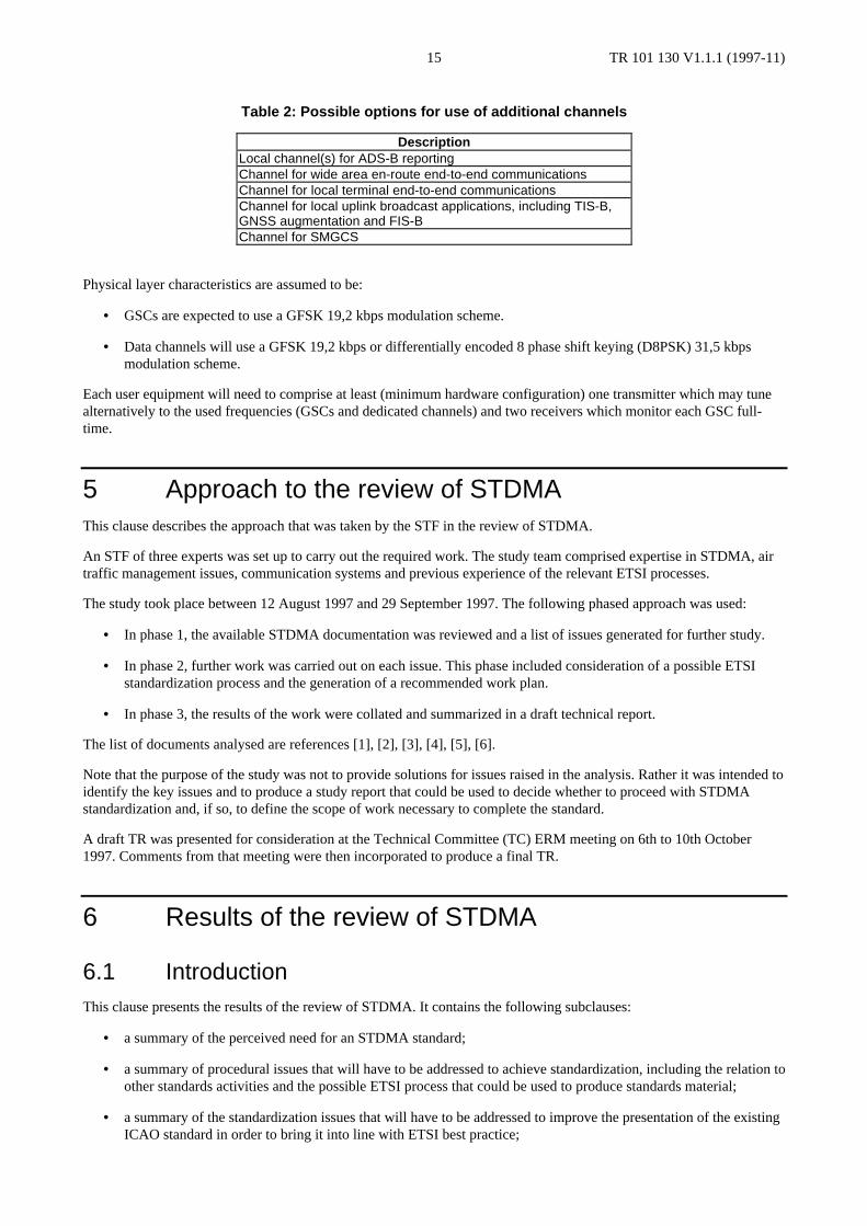
Additional channels may be employed specifically for a particular application, or group of applications. A number ofoptions are possible as illustrated in table 2. These options may be applied individually, or in combination, recognizingthe limited number of receivers available on aircraft.
TR 101 130 V1.1.1 (1997-11)15
Table 2: Possible options for use of additional channels
DescriptionLocal channel(s) for ADS-B reportingChannel for wide area en-route end-to-end communicationsChannel for local terminal end-to-end communicationsChannel for local uplink broadcast applications, including TIS-B,GNSS augmentation and FIS-BChannel for SMGCS
Physical layer characteristics are assumed to be:
• GSCs are expected to use a GFSK 19,2 kbps modulation scheme.
• Data channels will use a GFSK 19,2 kbps or differentially encoded 8 phase shift keying (D8PSK) 31,5 kbpsmodulation scheme.
Each user equipment will need to comprise at least (minimum hardware configuration) one transmitter which may tunealternatively to the used frequencies (GSCs and dedicated channels) and two receivers which monitor each GSC full-time.
5 Approach to the review of STDMAThis clause describes the approach that was taken by the STF in the review of STDMA.
An STF of three experts was set up to carry out the required work. The study team comprised expertise in STDMA, airtraffic management issues, communication systems and previous experience of the relevant ETSI processes.
The study took place between 12 August 1997 and 29 September 1997. The following phased approach was used:
• In phase 1, the available STDMA documentation was reviewed and a list of issues generated for further study.
• In phase 2, further work was carried out on each issue. This phase included consideration of a possible ETSIstandardization process and the generation of a recommended work plan.
• In phase 3, the results of the work were collated and summarized in a draft technical report.
The list of documents analysed are references [1], [2], [3], [4], [5], [6].
Note that the purpose of the study was not to provide solutions for issues raised in the analysis. Rather it was intended toidentify the key issues and to produce a study report that could be used to decide whether to proceed with STDMAstandardization and, if so, to define the scope of work necessary to complete the standard.
A draft TR was presented for consideration at the Technical Committee (TC) ERM meeting on 6th to 10th October1997. Comments from that meeting were then incorporated to produce a final TR.
6 Results of the review of STDMA
6.1 IntroductionThis clause presents the results of the review of STDMA. It contains the following subclauses:
• a summary of the perceived need for an STDMA standard;
• a summary of procedural issues that will have to be addressed to achieve standardization, including the relation toother standards activities and the possible ETSI process that could be used to produce standards material;
• a summary of the standardization issues that will have to be addressed to improve the presentation of the existingICAO standard in order to bring it into line with ETSI best practice;
TR 101 130 V1.1.1 (1997-11)16
• a summary of the technical issues that will have to be addressed to complete the specification of the existingsystem.
6.2 The need for STDMA
6.2.1 Market need
Some airlines have expressed a need for the applications supported by STDMA (see "Minutes of AirlineWorkshop" [18]), establishing a market need for the system. In addition, the system has the potential to offer a low costdata link supporting a range of applications that is affordable by General Aviation users.
6.2.2 Technical need
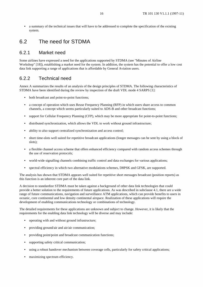
Annex A summarizes the results of an analysis of the design principles of STDMA. The following characteristics ofSTDMA have been identified during the review by inspection of the draft VDL mode 4 SARPS [1]:
• both broadcast and point-to-point functions;
• a concept of operation which uses Reuse Frequency Planning (RFP) in which users share access to commonchannels, a concept which seems particularly suited to ADS-B and other broadcast functions;
• support for Cellular Frequency Planning (CFP), which may be more appropriate for point-to-point functions;
• distributed synchronization, which allows the VDL to work without ground infrastructure;
• ability to also support centralized synchronization and access control;
• short time-slots well suited for repetitive broadcast applications (longer messages can be sent by using a block ofslots);
• a flexible channel access scheme that offers enhanced efficiency compared with random access schemes throughthe use of reservation protocols;
• world-wide signalling channels combining traffic control and data exchanges for various applications;
• spectral efficiency in which two alternative modulations schemes, D8PSK and GFSK, are supported.
The analysis has shown that STDMA appears well suited for repetitive short messages broadcast (position reports) asthis function is an inherent core part of the data link.
A decision to standardize STDMA must be taken against a background of other data link technologies that couldprovide a better solution to the requirements of future applications. As was described in subclause 4.1, there are a widerange of future communications, navigation and surveillance ATM applications, which can provide benefits to users inoceanic, core continental and low density continental airspace. Realization of these applications will require thedevelopment of enabling communications technology or combinations of technology.
The detailed requirements for these applications are unknown and subject to change. However, it is likely that therequirements for the enabling data link technology will be diverse and may include:
• operating with and without ground infrastructure;
• providing ground/air and air/air communication;
• providing point/point and broadcast communication functions;
• supporting safety critical communication;
• using a robust handover mechanism between coverage cells, particularly for safety critical applications;
• maximizing spectrum efficiency.

TR 101 130 V1.1.1 (1997-11)17
The capability of VDL modes 2, 3 and 4 and mode S squitter to support the applications listed in subclause 4.2 is asubject of debate. STDMA has certain features that are not provided by any other proposed VHF data link in ICAO.These unique functions include:
• operation with no ground infrastructure;
• air-to-air communications, both with and without the presence of ground stations;
• broadcast communications, both from ground and airborne users.
Note also that this review has not attempted a detailed comparison of how well VDL modes 2, 3 and 4 support end-to-end applications such as AOC, FIS etc. Hence, although STDMA as defined in Draft VDL mode 4 SARPs claims [2] thepotential to offer an improved throughput compared with mode 2 because of the use of reservation protocols, there areas yet no model results to support this claim. Similarly, the reviewers have not found any side by side comparisons ofmode 3 and mode 4 performance.
The reviewers have recommended that any future STDMA standard should be developed in two stages(see subclause 6.3). The first stage would develop the part of the system that would support ADS-B and would enable aside by side comparison with the mode S squitter technology. End-to-end communication would be added in the secondstage and it is recommended that a comparison between the VHF modes is made during this stage and, if possible, themode 4 protocols optimized using experience gained from modes 2 and 3. If possible, opportunities to provideinteroperability and transition paths between the different VDL modes should be identified and exploited.
6.2.3 Current progress towards standardization
The most recent ICAO activity relevant to VDL standardization was the AMCP Working Group D (WGD) seventhmeeting in Madrid from 8 - 17 April 1997. The key results of the meeting were:
• Mode 3 VDL standardization: A key service supported by mode 3 is voice communication. Difficulties havebeen encountered in proving the operation of the vocoder, which is required to provide voice services. Thedifficulties relate to achieving acceptable discrimination and clarity of voice communication against the highlevels of background noise encountered in the cockpit. It was accepted at the meeting that the problems with thevocoder would probably delay the completion of the validation process for mode 3 by at least two years. Notethat the development of the data functions of mode 3 have been influenced greatly by the need to provideintegrated voice and data. Without the vocoder, it is still possible to standardize VDL mode 3 as an ATN datacommunications system with higher performance than VDL mode2.
• VDL mode 4 (ICAO term for STDMA): The latest version of the SARPs were presented [3]. Discussions wereheld to decide if mode 4 could enter a validation phase. Objections to the operation of mode 4 were raised on thegrounds that the algorithms for frequency sharing were not proven. It should be noted that overall acceptance ofmode 4 is hampered by its possible use for ADS-B. Some states, particularly the USA, are committed to usingmode S for ADS-B and are unconvinced by the need to consider alternative systems.
There is therefore considerable uncertainty as to the way forward for data link standardization within ICAO and this ishampering progress with the development of VDL mode 4:
• From a technical viewpoint, it may be better to proceed with standardization in order to provide a stable andvalidated reference system which can then be considered against evolving operational requirements. Since futurerequirements will be quite hard to determine in detail for any system considered for standardization, a key featureshould therefore be flexibility and growth potential.
• On the other hand, an alternative approach is to wait until there is a stable operational requirement beforeproceeding with standardization activity. This approach would cause significant delay to the progress of VDLmode 4 and greatly reduce its chances of gaining world-wide acceptance. According to current ICAO plans, VDLmode 4 is unlikely to be standardized before 2000.

TR 101 130 V1.1.1 (1997-11)18
6.2.4 Ongoing trials projects
There are many tests and evaluation projects involving STDMA (note that the equipment used in these trials is based onan early STDMA specification which pre-dates the VDL mode 4 draft SARPs upon which the proposed ETSI standardwould be based). Some are finished and some have not yet started, but some of the most relevant ones that are presentlyongoing are described below:
• NEAN (sponsored by EC DG VII) The largest European STDMA activity is known as the North EuropeanADS-B Network (NEAN). Under NEAN, an ADS-B capability is being created through a network of groundstations and mobile STDMA equipment that is compliant with the emerging VDL mode 4 draft SARPs and whichis being installed in commercial aircraft and airport vehicles. The network spans Germany, Denmark andSweden, and once position reports are received by a ground station they are then distributed throughout thenetwork to air traffic control and other users. There will be 15 ground stations in the NEAN project and 16aircraft equipped including four 747s, two DC9s, two F28s and a helicopter involved in North Sea operations.Around 30 ground-vehicles will also be equipped. NEAN is a collaborative venture between the German, Danishand Swedish Civil Aviation Administrations and the following aircraft operators: Lufthansa, SAS, OLT, MaerskHelicopters and Golden Air. The UK CAA is leading the certification and validation parts of the project. TheNEAN ground network was completed in May 1997 and airborne installations will be completed by the secondhalf of 1997.
• NEAP (sponsored by EC DGVII) The North European CNS/ATM Applications Project (NEAP) is a sisterproject to the NEAN, with the same participants. Using the infrastructure implemented in the NEAN, the NEAPwill develop and demonstrate end-to-end (airborne and ground based) applications using the VDLmode 4/STDMA data link. The applications to be investigated in NEAP include: enhanced ATC surveillance(both while airborne and on the ground); uplinked support information for pilots, e.g. TIS data; uplinkeddifferential GNSS corrections and integrity data.
• FARAWAY ( sponsored by EC DG XIII) The objective of FARAWAY is to investigate the enhancedoperational performance of ground surveillance and aircraft navigation made possible through fusion of radar andADS-B data. The Faraway project is co-ordinated by Alenia Spa, Italy and involves ATM service providers andairlines in Germany, Italy and Sweden. Initially three Alitalia MD-82 will be equipped with STDMA and cockpitdisplay equipment and one ground station will be installed at Ciampino airport, Rome. The FARAWAY trialswill run from October 1997 to March 1998.
• MAGNET B ( sponsored by EC DG XIII) The objectives of Magnet B are to develop GNSS1 user segments, toassess their capability to meet the most demanding aviation requirements and to evaluate the benefits that userscan achieve from the integration of GNSS1 with a two-way data link. The Magnet B project is co-ordinated byDassault Electronique, France and includes participants from Germany, UK, Norway, the Netherlands andSweden. When practical trials start, it is expected that STDMA will be installed in an NLR aircraft in Hollandand a base station also located there.
• PETAL II (sponsored by EUROCONTROL) PETAL-II is a Eurocontrol project to investigate use of air-grounddata link to perform real-time CPDLCs. Petal II is using the two-way data link capability of STDMA to providethis application. STDMA ground stations were installed at the Maastricht Centre and at the EurocontrolExperimental Centre during March/April 1997.
These trials programmes have provided early demonstration of the use of STDMA for ADS-B applications. There is thepotential for integrating VDL mode 4 draft SARPs or ETSI standard compliant equipment with these trials in 1998 inorder to provide an extensive test bed for the validation of the VDL mode 4 draft SARPs or ETSI standard. The earlyestablishment of an ETSI standard is therefore desirable to provide a stable reference specification for development ofthis equipment.
6.2.5 Summary
In deciding whether to standardize STDMA, the main evidence to be taken account of is therefore:
• a requirement for STDMA has been expressed by some airlines;

TR 101 130 V1.1.1 (1997-11)19
• the ability of STDMA to offer a flexible communication system and, in particular, its ability to providecommunication functions that are not currently supported by other VDL modes:
• operation does not require ground infrastructure;
• air-to-air communications, both with and without the presence of ground stations;
• broadcast communications, both from ground and airborne users.
• its ability to offer a solution for ADS-B applications;
• progress of the STDMA standard within the ICAO forum is slow and there is no prospect of achieving an earlystandard.
ETSI can provide a rapid route for standardization through its flexible standards development process:
• making possible the establishment of a regional standard;
• providing a benchmark for Commission funded trials activity;
• promoting the development of the operational uses of STDMA.
ETSI can therefore provide a path to promote a system being developed by European industry.
In developing a possible standard, account should be taken of the development of other standards, notably:
• Mode S squitter as an alternative ADS-B enabling technology;
• VDL modes 2 and 3, taking opportunities, wherever possible, to unify the point-to-point functions of the threemodes.
6.3 Procedural issuesThe production of an ETSI standard must take account of and, wherever possible, co-ordinate with other standardsactivities related to STDMA. The necessary activities identified in the study include:
• co-ordination with standards being developed by ICAO AMCP, possibly through exchange of change requests;
• taking account of emerging standards for ADS-B being produced by Radio Technical Commission forAeronautics (RTCA);
• co-ordination (and potential resource sharing) with VDL mode 4 Minimum Operational PerformanceSpecifications (MOPS) being developed by European Organization for Civil Aviation Electronics (EUROCAE)WG-51;
• information sharing with the Airline Electronic Engineering Committee (AEEC) in order to encourage AEEC todevelop common interface standards;
• co-ordination with groups developing STDMA-derived standards in other application areas, notably land andmaritime.
As a result of the analysis of the VDL mode 4 standards material upon which an ETSI standard would be based, it hasbeen concluded by the STF that it will take approximately one year to produce an ETSI standard with the sameboundaries as the current ICAO standard, followed by a further 6 months to produce an approval and protocolconformance specification. Since there is an urgent need to produce a standard to support trials activity carried out in1998, a phased approach is recommend in which:
• An initial TS (TS1) is produced which will define a system targeted at ADS-B applications and is the mostnatural extension of the STDMA system. It is estimated that such a TS could be produced after 6 months work.
• A second TS (TS2) is produced which will define an enhancement to support point-to-point communication. Thiscould be completed after a further 6 months work.
TR 101 130 V1.1.1 (1997-11)20
• A third TS (TS3) is produced to contain the approval and protocol conformance specification. An initial versionof this would be produced after the first 6 months in order to support the trials use of the system defined by TS1.There would be a later extension produced after the completion of TS2 to define the full approval and protocolconformance specification for an operational system based on the combined TS1 and TS2. Note that it might bepreferable to separate TS3 into two TS's, corresponding to conformance specifications for TS1 and TS2respectively.
• Once TS1 and TS2 are complete, it is proposed that they are submitted for formal approval to produce an EN.
• It is proposed that the required work is carried out by two sub groups:
• The first one will work on the physical layer;
• The second one will work on the Logical Link Control (LLC) and network layer, which, in ICAO SARPsterminology includes the link layer (Media Access Control (MAC) sublayer, VDL mode 4 Specific Services(VSS) sublayer, Data Link Service (DLS) sublayer, Link Management Entity (LME) sublayer) and thesubnetwork layer.
It will be necessary to set up a liaison activity between the two groups to define the interfaces between the two layersand to liaise with other standards activities. This interface will probably evolve with the technical work within the twosubgroups.
More detail on the procedural issues relevant to the standardization of STDMA is contained in annex B.
6.4 Standardization issues
6.4.1 Introduction
The standardization of STDMA will have to follow the usual methodology:
• define precisely the needs and the requirements that this standard will have to satisfy;
• choose the technical solutions that will permit to offer solutions to the previously identified needs andrequirements;
• write a standard which clearly and unambiguously reflects the solutions adopted in the standard.
The issues raised by the review process are discussed in this subclause. More detail on STDMA standardization issues iscontained in annex C.
6.4.2 The need for a clear system concept
6.4.2.1 The need for clear interfaces
It is necessary to summarize the various functions that STDMA will have to support. Considering that STDMA isintended to support a lot of different interfaces, it may be necessary to organize the offered functions in relation to theirmain characteristics e.g. connection or connection-less oriented. The defined interfaces will have to be complete withnot only the parameters of the requirement but also with the indications returned in case of failure or impossibility tosatisfy the service.
6.4.2.2 Clear boundaries for the system
Clear boundaries of the system will have to be defined. These boundaries concern the channel management and the waythe functions are supported. One may distinguish between three main approaches to this problem:
• To define a very simple communication system operating on a frequency. This frequency may vary in a givenfrequency bandwidth.
• To define in addition to the previous communication system tools which may make it possible to manage variouschannels and to organize various functions sharing a same resource.

TR 101 130 V1.1.1 (1997-11)21
• To build a fully integrated telecommunication system capable of taking into account the various servicesrequirement, their need of bandwidth and possible competition between these requirements.
This problem has technical implications. The solution chosen will impact greatly on the architecture of the standard.Because the detailed requirements for services are not yet fully defined (see subclause 6.2.2), it is felt that the third ofthese approaches is unlikely to be practical. Instead it is recommended that a flexible standard is produced through acombination of the first and second approaches.
6.4.2.3 Clear mode of operation in the given spectrum
The availability of the targeted spectrum has to be clearly identified as well as the possible constraints. One may be invarious scenarios ranging from the exclusive use of the bandwidth to the coexistence or inter operation with othersystems. As a priority, the standardization work should consider this issue and provide a resolution to it.
6.4.3 The reliability issue
Concerning a telecommunication standard in the aeronautical field, STDMA will have to address the reliability issue. Inthe DGXIII Treaty 8 report [10], the functions described have an associated reliability requirements. These requirementswill have consequences on the design of the STDMA standard.
The reliability issue may be addressed throughout all the whole STDMA standard. For instance the reservation schemewhich is a corner stone of the STDMA draft standard will have to address with this concern.
Moreover the reliability issue imposes that a conformance testing specification will be worked out to ensure a properoperation of the system.
6.4.4 Structure and presentation of the standard
The standard will be written in accordance with the chosen architecture and in accordance with ETSI best practice.
6.5 Technical issuesThis subclause describes the technical issues that will require investigation during the standardization process. There arefour kinds of technical issues:
• provision of procedures which are not yet specified in the draft standard;
• the optimization of the parameters which are used in the standards;
• the possible enhancement of the system;
• the validation of performance with respect to requirements.
The level of effort required to resolve these issues varies between topics. Some will require substantial effort.
More detail on the technical issues relevant to the standardization of STDMA is contained in annex D.
6.5.1 The missing procedures
6.5.1.1 Secondary timing and positioning protocol
The timing and positioning recovery procedure when local UTC source fails is mentioned in the draft but is notspecified. A clone of the GNSS procedure based on position broadcast of remote aircraft and tracking of their burstsynchronization may suffice. The main difficulties are in the definition of hardware and software timing requirements forthis purpose and in providing tests to demonstrate compliance.

TR 101 130 V1.1.1 (1997-11)22
6.5.1.2 Channel management
The set of channel management procedures is very important. If the committee plans to include them in the draftstandard then there will be the need to specify numerous protocols for dynamic channel assignment and for dealing withpossible erroneous behaviours of the system in case of protocol failure.
6.5.1.3 High priority reservation pre-emption protocol
This procedure is mentioned in the ICAO standard but not yet specified. Algorithms exist in case of a centralizedprotocol where a central agent rules the medium access. In a distributed protocol such as that used for STDMA, theproblem might be less easy since the pre-emption poses problems in the case of contention between different priorities.
6.5.2 The optimization parameters
Optimization of parameters in the ICAO standard should not require too much resource, provided the committee has thetechnical expertise to achieve it, or can rely on technical database and simulation tools. A number of STDMA simulationand modelling studies are currently in progress as part of the ICAO process and it is hoped that this expertise can bedrawn upon to carry out the work.
6.5.3 The system enhancements
6.5.3.1 Superframe parameters
Some clarification is required of the superframe parameters. This is not expected to require significant resource to solve.
6.5.3.2 Warming up procedures
The system recovery after a long channel failure or when an aircraft first enters STDMA coverage may be consideredtoo slow, although this may not prove to be operationally significant. A study must be carried out to investigate thisissue and possibly to propose an enhancement to the standard.
6.5.3.3 Slot reuse and Co-Channel Interference (CCI) conditions
The CCI condition for slot reuse may be incomplete since it considers only one transmitter per slot, while severaltransmitters are possible. In this case the CCI conditions may need to be adapted and the resulting broadcast conditionmay be more complicated. CCI conditions based on Received Signal Strength Indication (RSSI) power measurementinstead of position estimate may prove to be an interesting alternative to the currently proposed scheme. It may bepossible that CCI conditions and broadcast conditions could be simplified and merged to a single condition based onRSSI with negligible performance degradation. The issue of slot re-use therefore needs substantial study and validationthrough modelling. Once again, existing simulation work could be used to assist this work.
6.5.3.4 Distributed clock software synchronization
A timing mechanism that does not rely on an external source might be investigated to increase the integrity of thesystem. Software synchronization mechanisms provide interesting results but require a priori a communication whosereliability is independent of clock synchronization, see references [11], [12], [13]. Investigations to find possible lessdemanding protocols are recommended.
6.5.3.5 Reaction to long jamming periods
Procedures to deal with jamming and other persistent noise events need to be investigated.

TR 101 130 V1.1.1 (1997-11)23
6.5.4 Viability check and performance study
6.5.4.1 Modulation choice
STDMA is sufficiently flexible to support two modulation types. The choice of modulation type may need further study.However for ADS-B and Differential GNSS (NABS) applications, it is expected that GFSK will prove to offer the bestsystem performance (see reference [5]). A study needs to be carried out to investigate the relative advantages anddisadvantages of the possible modulation types and to make recommendations for the best scheme as a function ofservice provided.
6.5.4.2 The slot reuse and broadcast reliability
The periodic broadcast is the most demanding function in STDMA. The access protocol needs to guarantee, withsufficient reliability, the performance of the network in the case of heavy traffic, or any other critical conditions againstwhich STDMA needs to be tailored. For example the E-TDMA study (see reference [10]) outlines a worst case en-routesituation of 570 aircraft in a radius of 160 nmi, each aircraft broadcasting its position every six seconds. In this very caseit is necessary to check that the broadcast transmissions are received with enough range and enough reliability. Amodelling and simulation effort is required and an example is given in annex D. Reuse factor, average reception areaand reliability estimates are the parameters which should be derived as a result of this study and the result should beused to further develop the system concept including consideration of number of channels required, use of GSCs etc.
6.5.4.3 Remote and hidden node management
One should check under which conditions an aircraft could be visible for a second station and not for a third one. Onecase is the ground effect on ground stations. The committee should investigate the way to cope with this problem whichmay affect ground control.
7 Proposed work plan for STDMA standardization
7.1 IntroductionThis subclause presents a proposed work plan for STDMA standardization.
7.2 Key issues and recommended approachThe European Commission has indicated that it is desirable to produce an EN for STDMA. This is desirable because itadds force of European Law to the standard and will have most influence on the ICAO process. However, the procedurefor achieving an EN will result in delay which may not enable the full impact on the ICAO process to be realized. Asdescribed in subclause 6.3, the STF recommend that the development work is divided into three TSs. The first two ofthese TSs would then be submitted to the full voting procedure to produce an EN. This approach results in the earlyavailability of TC approved standards which can then be converted to EN status in the fullness of time.
7.3 Organization of the workThe recommendation derived from this study is to carry out the development work using the following procedure:
• build a set of functions and associated requirements that STDMA will offer;
• develop a clear system concept and architecture for the system;
• break the committee in charge of the standardization into two subgroups: The Transmission Techniques Groupand Protocol Design Group.
The Transmission Techniques Group should study the following points:
• determining an appropriate choice of modulation;
TR 101 130 V1.1.1 (1997-11)24
• specification of parameters concerning power limits, switching times, etc.;
• ensuring the interoperability with VDL mode 2 and other media such as ACARS VHF, voice VHF, navigationaids etc.;
• defining antenna requirements to ensure a nearly isotropic radiation;
• defining requirements and suitable techniques for timing synchronization.
The Protocol Design Group should study the following points:
• functions to be offered by STDMA and related interfaces;
• system concept definition, channel management and function management;
• timing synchronization for example, what form of distributed algorithm will be used to synchronize clocks);
• slot reuse algorithms;
• reliability issues in the STDMA functionality.
The two sub-groups will focus on the production of the following deliverables:
• An initial TS (TS1), which will define a system targeted at ADS-B applications and is the most natural extensionof the STDMA system. It is estimated that such a TS could be produced after 6 months.
• A second TS (TS2), which will define an enhancement to support point-to-point communication. This could becompleted after a further 6 months.
• A third TS (TS3) to contain the approval and protocol conformance specification. An initial version of this wouldbe produced after the first 6 months in order to support the trials use of the system defined by TS1. There wouldbe a later extension produced after the completion of TS2 to define the full approval and protocol conformancespecification for an operational system based on the combined TS1 and TS2. Note that it might be preferable toseparate TS3 into two TSs, corresponding to conformance specifications for TS1 and TS2 respectively.
In addition, the committee should consider whether a TR deliverable detailing the functions and facilities of the systemand the services and applications to be supported should be produced as an aid to explaining the purpose, interfaces andboundaries of the system. The TR should also specify the type approval requirements for the system so as to define thelevel of conformance testing necessary. Such a document could be produced at the start of the recommended work as ameans of providing a reference work for the study.
The committee will need to provide control and co-ordination of the overall activity. This will include:
• defining the terms of reference of each sub-group and ensuring that there is no duplication of effort;
• providing editorial control over the production of the TS document;
• providing liaison support with other standards bodies, notably ICAO, EUROCAE and International MaritimeOrganization (IMO).
Note that technical constraints may impose that TS1 and TS2 be within the same document (see subclauses B.3.5 andC.2.2).
As was discussed in subclause 6.2, account should be taken of the development of other standards, particularly VDLmodes 2 and 3, taking opportunities, wherever possible, to unify the point-to-point functions of the three modes. It isrecommended that a review of the current state of standardization of these standards is carried out prior to starting workon TS2 in order to decide on the need for TS2 and the required content of this part of the standard.

TR 101 130 V1.1.1 (1997-11)25
7.4 Timescales for the workIt is estimated that it will take 6 months to one year to complete the functional specification work. An additional 8months will be necessary to perform the radio approval and protocol testing. An initial timing chart is provided infigure 3 showing approximate timescales. It is recommended that a detailed planning activity is carried out at the start ofthe study. It may be necessary to increase the time taken to carry out the production of TS1, leading to slippage of thedelivery date. This will depend both on available resource and on the time taken to complete the first task (production ofthe TR). If additional time is necessary, it may be possible to reduce the time taken to produce TS2 so as to keep to theoverall planned timescales. The detailed planning must also take account of the timing of TC ERM meetings,particularly as a decision to proceed with the production of TS2 will have to be taken by that committee after thecompletion of TS1.
ID Task Name1 Clarify functions and facilities to be supported by STDMA
2 Technical Report
3 Develop and specify broadcast functions for STDMA
4 Technical Specfication 1 (TS1)
5 Develop and specify point to point functions
6 Technical specification 2 (TS2)
7 Develop conformance tests to support trials activities
8 Initial version of TS3
9 Develop conformance test to support operational system
10 Technical specificaiton TS3
11 Voting process for EN based on TS1/TS2
12 EN for STDMA
28-01
17-06
02-12
02-12
14-07
14-07
Jan Feb Mar Apr May Jun Jul Aug Sep Oct Nov Dec Jan Feb Mar Apr May Jun Jul Aug Sep Oct Nov Dec1st Quarter 2nd Quarter 3rd Quarter 4th Quarter 1st Quarter 2nd Quarter 3rd Quarter 4th Quarter
Figure 3: Initial study timescales (assuming start date 01/01/98)
7.5 Estimated resource requirementsAccording to the previous organization of the work and taking into account annex B, C and D for further refinement,one can estimate that a committee must be set up to cover a period of 20 months (in accordance with the timescales setout in figure 3). According to the initial timescales, this work can be divided between around 12 months for thefunctional specifications and around 8 months for the conformance testing issue. The exact number of meetingsnecessary is difficult to assess, but it could be assumed that the committees would have to meet at least every 2 months.Since it is probably unlikely that sufficient resources can be found within ETSI to enable the work to be carried outwholly by a committee, it is recommended that an STF is used to:
• carry out the bulk of the required work and provide specialist expertise in air traffic management and STDMA(estimated effort required is 14 man months, dependent on the level of expertise available within the committee);
• support the conception of the whole system including modelling and simulation of various possible approaches,dimensioning, ensuring reliability and performances of the system (estimated effort required is 6 man months);
• to carry out most of the work on the radio approval and conformance testing specification (estimated effortrequired is 10 man months).
Overall, therefore, it is recommended that over an elapsed period of 20 months, the effort required to carry out the workis estimated to be 30 months of contracted STF effort.
8 Conclusions and recommendationsIn accordance with CE Mandate M/239, a Special Task Force has carried out a study on the feasibility of standardizingself organized time division multiple access (STDMA) system requirements. The available specification material forSTDMA has been analysed to see what actions ETSI should take to:
• transfer the technical specification into a standard;
TR 101 130 V1.1.1 (1997-11)26
• complete all the required interfaces;
• identify areas needing particular attention;
• define the appropriate time schedule for any future work.
The following conclusions have been reached as a result of carrying out this review:
• STDMA appears to provide a flexible data link that has the potential to act as an enabling technology for a widerange of future Air Traffic Management applications. In particular, the system has been optimized to supportADS-B applications.
• There is a market requirement for the system.
• Although there are rival candidate systems for ADS-B, notably a system based on mode S squitter transmissions,there is, as yet, no international consensus on the eventual choice of data link for ADS-B and it is not certainwhen such a consensus could be reached.
• STDMA has a number of unique functions that differentiate it from other VDL standards, notably:
• operation with no ground infrastructure;
• air-to-air communications, both with and without the presence of ground stations;
• broadcast communications, both from ground and airborne users.
• Current trials activity urgently require the establishment of a standard in order to promote further understandingof the operational uses of STDMA.
• The current progress towards standardization of STDMA (known as VDL mode 4) within the ICAO forum isslow and there is no prospect of achieving an early standard.
• The current ICAO standards provide a reasonable starting point for ETSI standards but the review has identifieda number of presentational and technical issues that must be resolved before a standard can be produced. Theseissues include the need to:
• define clear interfaces, system boundaries and the mode of operation for the system;
• change the presentation of the standard to conform with ETSI best practice;
• define procedures that are currently absent from the standard including timing, channel management and pre-emption protocols;
• optimize certain parameters;
• consider possible system enhancements including alternative slot re-use algorithms based on RSSI andresistance to jamming and other interference sources.
• carry out system viability checks including modelling of broadcast delivery reliability and remote and hiddennode management.
The STF makes the following recommendations:
• A standardization activity for STDMA should be started within ETSI based on the existing ICAO standard. Theaims of the standardization activity should be to:
• respond to market need;
• support the development of the STDMA system, particularly the functions provided by system, namelybroadcast functions, air to air functions and operation without ground infrastructure, that are currently notsupported by any other VDL modes and which enable STDMA to support a wide range of applications and toprovide a data link in core continental, oceanic and low density continental airspace;
• provide a stable standard for trials assessment of ADS-B applications;

TR 101 130 V1.1.1 (1997-11)27
• provide extensions to the standard that are capable of supporting point-to-point communication.
• The deliverables for such an activity should consist of:
• An initial TS (TS1), which will define a system targeted at ADS-B applications and is the most naturalextension of the STDMA system. It is estimated that such a TS could be produced after 6 months.
• A second TS (TS2), which will define an enhancement to support point-to-point communication. This couldbe completed after a further 6 months.
• A third TS (TS3), which will contain the approval and protocol conformance specification. An initial versionof this would be produced after the first 6 months in order to support the trials use of the system defined byTS1. There would be a later extension produced after the completion of TS2 to define the full approval andprotocol conformance specification for an operational system based on the combined TS1 and TS2. Note thatit might be preferable to separate TS3 into two TS's, corresponding to conformance specifications for TS1and TS2 respectively.
• An EN based on TS1 and TS2. The voting process for this EN will start once both TS1 and TS2 arecomplete.
• In addition, consideration should be given to the production of a TR deliverable detailing the functions andfacilities of the system and the services and applications to be supported. This would be useful as an aid toexplaining the purpose, interfaces and boundaries of the system. The TR should also specify the type approvalrequirements for the system so as to define the level of conformance testing necessary. Such a documentcould be produced at the start of the recommended work as a means of providing a reference work for thestudy.
• The committee in charge of the standardization should be divided into two subgroups : The TransmissionTechniques Group and Protocol Design Group.
• Overall, therefore, it is recommended that over an elapsed period of 20 months, the effort required to carry outthe work is estimated to be 30 months of contracted STF effort.
• Development of STDMA should take account of activities in other standards bodies. In particular, accountshould be taken of:
• VDL mode 2 standards and the emerging VDL mode 3 standards within ICAO. Some functions provided bySTDMA are also provided by VDL mode 2 and mode 3 and any further development of these functionswithin STDMA should be fully justified in terms of operational advantage and user benefit. It isrecommended that a review of the current state of standardization of these standards is carried out prior tostarting work on TS2 in order to decide on the need for TS2 and the required content of this part of thestandard;
• emerging standards for ADS-B being produced by RTCA and also alternative ADS-B system solutions suchas mode S squitter;
• the need for co-ordination (and potential resource sharing) with VDL mode 4 MOPS being developed byEUROCAE WG-51;
• the potential benefits of information sharing with AEEC in order to encourage AEEC to develop commoninterface standards;
• the need for co-ordination with groups developing STDMA-derived standards in other application areas,notably land and maritime.

TR 101 130 V1.1.1 (1997-11)28
Annex A:Design principles of STDMA
A.1 Functions and traffic requirement addressed bySTDMA
Typical operational scenarios to be supported by STDMA mix broadcast applications (and, in particular, ADS-Bapplications) with point-to-point applications (CPDLC etc.).
ADS-B applications are expected to be the main traffic contributor to STDMA. ADS-B requires that aircraft positionparameters are periodically broadcast to other aircraft (air-air) and to ground stations (air-ground). The ADS-Boperational environment places special requirements on the design of a multiple access technique to be employed.
• Firstly, aircraft ADS-B transmitters are highly mobile such that the environment around any given surveillancereceiver is rapidly changing.
• Secondly, it is necessary that for air-air ADS-B applications, the system should be able to operate autonomouslywithout a central controller in many environments, including oceanic and low density continental airspace.
• Finally, ADS-B must appear seamless to an ADS-B surveillance receiver; i.e. an airborne sensor must always beable to hear all nearby aircraft reports regardless of their location with respect to any "cell" or "sector"boundaries.
Point-to-point functions are also important requirements in order to support ATN protocols and these could besupported by STDMA if the point-to-point functions defined within the ICAO VDL mode 4 draft SARPs areincorporated into the ETSI standard. However, its performance will need to be compared with that offered by otherVDL standards such as modes 2 and 3.
Note that in order to achieve optimum use of the data link, it may be necessary to partition the different applications onto different channels and to use different parameters (e.g. guard time, modulation scheme, slot length etc.) for eachchannel. Obviously, this increases the system complexity and is probably not desirable if it can be avoided.
Because ADS-B requirements dominate the expected operational scenario, it is expected that STDMA will be optimizedwith respect to this service. Also, because STDMA could support point-to-point communication (particularly if suchsupport is on a separate channel), it is expected that it will provide a potential solution for end-to-end applications.
A.2 STDMA system concepts and frequency allocation
A.2.1 IntroductionThe system concept should take account of the frequency shortage in Europe and elsewhere. A concept based on distinctcoverage cells relies on different frequency cells for data link activity and will probably have to use spectrum currentlyused for voice communication. There will therefore be difficult transition issues to solve. A possible solution in which afrequency for data link is assigned to each air traffic sector is probably not practical in the early days since there will beinsufficient spectrum (it is possible that the migration of voice to 8,33 kHz channels may free up some spectrum in thelonger term and if not limited to upper airspace only). A better approach may be to define a large region served by thesame frequency and which operates near to capacity in the early days, and to reduce the size of that region as the datalink load increases and as more spectrum becomes available. Alternatively, use of a system that allows re-use of thesame channel may be a better, more efficient approach. This subclause explores these issues in more detail.

TR 101 130 V1.1.1 (1997-11)29
A.2.2 System conceptCFP is a VHF coverage concept which is organized into distinct coverage cells, such that there is no overlappingcoverage between cells using the same frequency. RFP is a VHF coverage concept which allows the same frequency tobe used on adjacent cells, taking advantage of capture effect on packet reception.
The proposed STDMA concept uses RFP and does not require specific CFP. Note, however, that STDMA does notpreclude the use of CFP in its channel management architecture.
CFP has the advantage over RFP that it allows a very simple and centralized channel access management around everybase station. RFP needs more sophisticated distributed channel access which takes into account interference from remotestations and hidden nodes. However the RFP concept presents numerous advantages over CFP as listed below:
• CFP consumes greater frequency resource since strict cell mapping would require at least four distinct frequencysets (experience with GSM suggests that at lest six distinct frequency sets would be required). In theory RFPwould need only one set of frequencies. Furthermore frequency planning on empty areas (i.e. without groundstations) would be difficult to manage.
• In general CFP is difficult to manage in a dynamic configuration. For example as air traffic load increases it willbe difficult to add new frequencies in each cell or to reduce the size of cells. Adding extra frequencies in RFP istrivial. Note that, in RFP, a higher load on the same frequency may simply lead to smaller link range which maybe tolerable if the available range does not drop below critical values.
• RFP does not need a channel hand-over protocol between cells. In CFP, handover is a potentially weak part ofthe system since channel misallocation could disrupt the communication link. STDMA can use the same channelon two adjacent cells, thus neighbouring ground stations will be able to monitor the air traffic beyond their owncell boundary.
The system concept can have an important impact on the data link protocols. For example:
• Aircraft moving from one ground station to another in an RFP concept, require co-ordination of coverage inoverlapping regions to ensure that there is no channel contention. Such co-ordination could be provided by aground network (with resultant networking design, implementation and running costs) or (preferably) could beprovided by link management protocols defined as part of the data link standard.
• Aircraft moving from one cell to another in a concept using distinct coverage cells also require co-ordination. Forpoint-to-point communication, this involves maintaining peer-to-peer links and is achieved by ATN protocols.The situation is more difficult if ADS-B applications are being supported, since all aircraft in the overlappingregion needs to receive transmissions from all other aircraft in the region, some of which will be operating ondifferent channels. In this case, the data link protocols need to support parallel operation on more than onechannel.
Therefore ADS-B applications suggest the use of global channels, since otherwise, a non-trivial co-ordinationmechanism will be needed to maintain a full surveillance picture for all users in the transition region from one frequencyto another. In this case, RFP management, which is supported by STDMA, is expected to be a key for such anapplication. ADS-B ground-air applications could be implemented using a CFP concept with the transition from onefrequency to another controlled by the ground system. However, since ADS-B could be used to provide the groundbased surveillance service, the control mechanism would have to be of the highest integrity and could result in costlyground networking solutions.
Furthermore, local constraints may impose CFP for VDL. In this case, the STDMA concept does not preclude the use ofany particular channel management technique, with or without CFP in its channel architecture. STDMA will provide theelements needed for the implementation of the preferred management scheme.
A.2.3 Frequency allocationThe bands currently allocated to the aeronautical service by ITU and potentially available for data link are:
• VHF with 50 and 25 kHz channelization (currently used for navigation and VHF communications).
• L-band with 1 and 8 MHz channelization (currently used for navigation and secondary surveillance radar).

TR 101 130 V1.1.1 (1997-11)30
Both of these bands have advantages and disadvantages for use by an ADS-B system:
• Power requirements: Propagation path loss is proportional to the transmit frequency. This generally allowssystems operating in a lower frequency band to use less transmit power than a comparable system at a higherfrequency. Since the transmitters are airborne-based for this service the advantage of lower power could be animportant consideration, particularly for the General Aviation (GA) market.
• Spectrum availability: The VHF band is constrained due to current use world-wide. Given the current constraints,a system operating in this band must operate within the channelizations of 50 or 25 kHz to "fit in" amongstcurrent assignments. Currently VHF communications channels are in great demand. Therefore, initially findingand co-ordinating the international use of one or more of these channels solely for ADS-B may be difficult.However, depending on the actual installed implementation of navigational aids, there may exist the possibility tointermix ADS-B channels in that portion of the VHF band. In addition to the old 112,0-136,0 kHz band assignedby ITU for aeronautical functions there are also new 25 kHz channels assigned to aviation by ITU in the136,0-137,0 kHz band of which four of them have been designated by ICAO for data link functions. WithinL-band it may also be possible to co-ordinate a global channel due to the nature of the current ICAO band planfor Distance Measuring Equipment (DME) channel pairing, where one channel of the DME pair overlaps theSSR portion of the band. Since that DME channel pair cannot be used because of interference with secondarysurveillance radars, then one channel of the pair is for the most part unused and could provide a clear channel.
STDMA operates in the VHF band and therefore offers the potential for a low power and hence low cost data link.However, problems of VHF channel congestion will have to be solved to allow a suitable allocation to be made for itsuse.
A.3 STDMA modulation scheme and physical layer
STDMA is based on high speed (10 to 30 kbps) channels in order to satisfy the load needed by the traffic requirement.Among its optional scheme there is a modulation scheme GFSK at 19,2 kbps, which is resistant to noise (Signal to NoiseRatio (SNR) of 7 dB) which is needed for high link reliability. Furthermore it allows a good frequency reuse and isparticularly well adapted for RFP. In particular ADS-B applications would need the use of a global channel with thefollowing requirements:
• use of a modulation scheme that can tolerate CCI from other users on the same channel (this points towards lowerdata rate);
• a relatively large guard time to enable a user to receive transmissions from distant users (resulting in a reducedchannel capacity).
Point to point communications in ATN protocols would require:
• use of a modulation scheme that maximizes data rate (this may points towards schemes that have relatively poorCCI performance, which limits frequency reuse but ATN protocols could be implemented in CFP);
• a guard range targeted at the expected coverage range for each cell (probably results in a smaller guard time thanused for a concept that uses a global channel and therefore is a more optimum use of the channel leading tohigher capacity).
STDMA proposes an alternative modulation scheme which is D8PSK at 31,5 kbps.
A.4 STDMA Access protocolsGeneral access protocols for VDL need to be derived:
• VDL mode 2 uses random access on a shared channel for ground-air communication.
• VDL mode 3 uses ground controlled TDMA for ground-air communication.

TR 101 130 V1.1.1 (1997-11)31
• STDMA offers a slot reservation process which is particularly suited to meet the requirements for periodicbroadcast of short packet as specified in ADS-B. The channel access of STDMA is distributed which is importantto support RFP and does not need a centralized management (while not precluding it). It allows the system towork without ground control (opening up the possibility of air-air point-to-point communication).
STDMA therefore offers a flexible channel access scheme that offers enhanced efficiency through the use of reservationprotocols and distributed access.
A.5 STDMA interoperability with other standardsSTDMA, as defined in VDL mode 4 draft SARPs, will mandatorily be backward compatible with ICAO VDL mode 2.
TR 101 130 V1.1.1 (1997-11)32
Annex B:Procedural issues
B.1 IntroductionThis clause describes a number of procedural issues relevant to standardization of STDMA:
• the relationship to other standards;
• the selection of a standardization route.
B.2 Relationship to and co-ordination with otherstandards
This clause describes the various standardization activities relevant to STDMA.
B.2.1 ICAO - International Civil Aviation OrganizationGlobal standards for aviation are published as annexes to the Chicago Convention. In annex 10 SARPs for AeronauticalTelecommunications are published, where VDL is one part.
The SARPs material is prepared by ICAO panels of experts. Several different panels can be identified which have aninterest in the area of STDMA:
1) AMCP - Aeronautical Mobile Communications Panel: This panel has already published standards forsatellite communication and is currently working on High Frequency (HF) and VHF Digital Link (VDL)standards. Draft VDL mode 4 SARPs have been developed by the AMCP. The documentation consists of:
• draft SARPs version 5.4 [1] and [3];
• draft Manual version 1.0 [2].
There was reasonable expectation of published standards for VDL mode 4 in 2000 on the assumption that asuitable panel meeting is held in 1999). However, ICAO has just announced that the next panel meeting(AMCP/5) will be held in Spring 1998. This is likely to result in further delay for VDL mode 4 sinceacceptance would now have to wait until the next panel meeting (AMCP/6) which is now more likely to be heldlater than 1999 (probably 2000).
2) ADSP - Automatic Dependant Surveillance Panel: This sets requirements for ADS applications and thedeliberations of this panel will therefore impact on the potential surveillance uses of STDMA.
3) GNSSP - Global Navigation Satellites Systems Panel: This sets requirements for GNSS technology andapplications and the deliberations of this panel will therefore impact on the potential navigation uses ofSTDMA, particularly with respect to the use of STDMA for differential correction uplinks. GNSSP is expectedto choose a specific data link in the near future for GNSS augmentation signals - STDMA is a candidate forsuch a data link.
4) AWOP - All Weather Operation Panel: This sets requirements for applications to support poor weatherconditions (i.e. poor visibility on approach and taxiing) and the deliberations of this panel will therefore impacton the approach and ground movement uses of STDMA.
5) SICASP - SSR Improvements and Collision Avoidance Systems Panel: This sets requirements forsurveillance systems and applications and the deliberations of this panel will therefore impact on the potentialsurveillance uses of STDMA, in particular the use of ADS-B for Airborne Separation Assurance (ASAS). Thenext panel meeting, SICASP-7, will be held in 2000. Sub-group 2 looks at ACAS and ASAS.

TR 101 130 V1.1.1 (1997-11)33
It is important that standards activities undertaken by ETSI are co-ordinated wherever possible with those carried out byICAO to ensure that standards for mode 4 do not diverge. However, because the ETSI process is more efficient, ETSIcan provide support to the ICAO process by providing an early standard which can later become adopted as ICAOSARPs.
B.2.2 RTCA - Radio Technical Commission for AeronauticsRTCA is an organization formed by the US industry. Special Committees are formed to carry out particular tasks, e.g.:
• SC172 - VHF Digital Link (VDL);
• SC186 - Automatic Dependence Surveillance Broadcast (ADS-B).
RTCA is publishing Minimum Aviation System Performance Standards (MASPS) and MOPS for ADS-B. ETSI needsto take account of these emerging standards for ADS-B in optimizing the standards for STDMA.
B.2.3 EUROCAE - European Organization for Civil AviationElectronics
EUROCAE is the European equivalent to the RTCA in the US. To some extent these two bodies co-operate and sharetheir results. Working Groups are formed with special tasks:
• WG41 is working on advanced SMGCS.
• WG47 is working on MOPS for mode 1 and mode 2 VHF data links.
• WG51 is working on ADS-B. EUROCAE MOPS based on VDL mode 4 draft SARPs which will only deal withthose parts of the standard necessary to support ADS-B applications, although it has not yet been determined howto (or even whether it will be possible to) make a suitable partition of ICAO SARPs to reflect this. The issue ofpartition also needs to be addressed for the ETSI work (see subclause C.2.2). Note that MOPS depend on SARPsbut could be available earlier (therefore MOPS will really be draft only until SARPs is published).
• WG 53 is working on the definition at a system level of the future data link applications. Decisions made in thisgroup could influence the targeted availability of STDMA.
A key issue is to align the development of ETSI standards for mode 4 with the MOPS development process, so a toprevent duplication of work. It is expected that draft MOPS will be available in mid-1998 and hence this would fitreasonably well with the development of the first ETSI TS proposed in subclause B.3.5.
B.2.4 AEEC Airline Electronic Engineering CommitteeThe AEEC is an airline organization which is defining standards for how equipment physically should be designed.Purpose is to ensure common interface standards at the lowest level (form, fit and function). AEEC is organized anddriven by ARINC, who are a leading airline operators communications service provider. It is important to inform AEECof ETSI standards activities in STDMA and to encourage them to provide suitable AEEC standards.
TR 101 130 V1.1.1 (1997-11)34
B.3 Selection of standardization route
B.3.1 ETSI documents and proceduresETSI can produce three different kinds of standardization documents:
• Technical Specification (TS);
• ETSI Standard (ES);
• European Standard (Telecommunications series) (EN).
These documents correspond to three different procedures for the elaboration of the document:
• The technical specification reflects the work of a technical committee and its agreement on the obtained work.The document is formally approved after work in sub technical committee by the technical committee.
• The ETSI specification is obtained from a technical specification if this ES is voted by ETSI members. ETSI hasa formal voting procedure which takes 16 weeks. This vote is only between ETSI members.
• A TS or an ES can become an EN. The document has to follow the public enquiry procedure. After this period ofexamination the document receives comments explained by countries represented at ETSI. These comments arethen treated during a resolution meeting which provides a formal document which is then proposed to the vote.After the result of the vote the document is either accepted or rejected.
It is understood that the EC wants an EN and this is desirable because it adds force of European Law to standard andwill have most influence on ICAO process. However, the procedure for achieving an EN will result in delay which maynot enable full impact on ICAO. The members of STF 109 believe that the type of document (TS, ES, EN) which is tobe started by ETSI around STDMA is a committee choice. However, a set of recommended deliverables are presented insubclause B.3.5.
B.3.2 Proposed approach to the workIn the following we try to divide the remaining work to do to obtain an STDMA specification and to giverecommendations about the amount of effort that is required to obtain this specification.
As usual in a radio telecommunication system we can divide the standardization activity in two sub groups which canwork quite independently:
• The first one will work on the physical layer;
• The second one will work on the LLC and network layer, which, in ICAO SARPs terminology includes the linklayer (MAC sublayer, VSS sublayer, DLS sublayer, LME sublayer) and the subnetwork layer.
It will be necessary to set up a liaison activity between the two groups to define the interfaces between the two layersand to liaise with other standards activities. This interface will probably evolve with the technical work within the twosubgroups.
The STDMA specification will require, as described in the standardization issues in subclause B.3.5 an attachedspecification concerning the radio type approval and conformance testing. STF 109 advise that it is possible to carry outthis work after the STDMA functional specifications are complete and the results could be gathered into a separatedocument (probably a TR or EG). However the work for the technical specification needs to take into account the needto be able to test the radio protocols. This criteria will be very important in defining the technical specification.
B.3.3 Physical layer workThe work for the physical layer seems to be the simpler. Mainly we find the following remaining points to study:
• determining an appropriate choice of modulation;
TR 101 130 V1.1.1 (1997-11)35
• specification of parameters concerning power limits, switching times, etc.;
• ensuring the interoperability with VDL mode 2;
• defining antenna requirements to ensure a nearly isotropic radiation;
• defining requirements and suitable techniques for timing synchronization.
The following effort is foreseen for the tasks involved in this work:
• For the modulation choice, the missing figures and the check of the interoperability with VDL mode 2, one canforesee that these issues can be solved with two or three sub-group meetings if convenient inputs are given beforethe meeting.
• The definition of antennas to ensure a nearly isotropic radiation can probably be solved in one sub-groupmeeting.
• The timing synchronization is the most difficult part of the physical layer. It can be estimated that this work willrequire between two to four meetings depending on the complexity of the choices . Moreover it is possible that ifa synchronization algorithm based on packets exchange is used then this will mix deeply the physical layer andthe network layer.
These tasks could be carried out independently of each other.
B.3.4 LLC and network layer approachThe work for the network layer is more important and will depend on the technical choices that will be done during thecommittee work. The following points need to be covered:
• functions to be offered by STDMA and related interfaces;
• system concept definition, channel management and service management;
• timing synchronization for example, what form of distributed algorithm will be used to synchronize clocks);
• slot reuse algorithms;
• reliability issues in the STDMA functionality.
The following effort is foreseen for the tasks involved in this work:
• We can foresee that the discussion about the functions to be offered by the STDMA standard may be solved intwo meeting with proposals before the first meeting. The proposal will be discussed during the first meeting.Another meeting may be necessary if there is a lack of expertise in the aeronautical fields. With the selectedfunctions to be offered by STDMA we have to attach precise requirements. These requirements will deal withbandwidth, access delays, reliability . It could be useful if at the end of this work the committee will be able todefine a model for the traffic that STDMA will have to support. This model will be used to set up objectivecomparisons.
• The clear definition of the functions to be offered with their attached requirements will be the basis of thedefinition of the system concept. The channel management and quality of service management is deeply linkedwith the definition of the system concept. This work may call for modelling, simulations, objective comparisonsbetween various approaches. There may need to be a formal proof to ensure proper operation of the system. Onecan evaluate that this work will require between two to six meetings. It is likely that the time required to carry outthis work, which will probably require simulation and modelling, could be reduced with the help of an STF.
• The timing synchronization is an independent work that can be done independently of the previous two maintasks. Depending on the solution that will be chosen we can evaluate the amount of work between one to fourmeetings.
• The slot reuse is also an independent task. This work will require simulation and analytical models. This a verytechnical task where the help of a STF could be useful. The duration of this work can be evaluate between two tofour meetings.

TR 101 130 V1.1.1 (1997-11)36
• Reliability issues can be considered as a general task that is to be considered in all the procedures that will bedefined.
We can notice that in the physical layer the schedule is less tied than in the network layer. We have interaction betweenthe work in the physical group and the work in the network group especially one the following points: timingsynchronization, slot reuse and modulation choice. According to this division of the work one can see that the criticalpath is within the protocol work and mainly on the system concept definition and the corresponding procedures to offerthe functions.
B.3.5 Phased approach to standard production and proposedtimescales for the work
Actually it is possible that a further division in the standardization work can be introduced. This split comes from adivision between the functions offered by STDMA. These parts will be:
• a system targeted at ADS-B applications;
• enhancement of the system to support point-to-point communication and compatibility with modes 2 and 3.
The verification that such a split is possible should be an early sub-group task. Deliverables associated with each partare discussed below.
An initial TS (TS1) will define a system targeted at ADS-B applications and is the most natural extension of theSTDMA system. The TS would provide a stable baseline for equipment to be produced in mid-1998 to support trialsactivity.
The offered functions will be as follows:
• Autonomous scenario, consisting of:
• autonomous aircraft scenario (i.e. no ground station);
• periodic broadcast protocol;
• incremental broadcast protocol;
• combined incremental/periodic broadcast protocol;
• random access protocol;
• autonomous net entry;
• Ground station functions, consisting of:
• directed request protocol;
• procedures for ground directed control.
A next TS (TS2) will define an enhancement to support point-to-point communication. Although derivation of thenecessary functions could be based around the current draft ICAO SARPs [1, 2], the timescales for production of thisTS (say late 1998) would allow a detailed study of the usage of a separate data communication channel and thecompatibility with modes 2 and 3 to be examined in detail. Possible modifications to optimize the mode 4 standard fordata communications could be proposed at this stage.
The proposed functions of TS2 would be:
• End-to-end VSS protocols, consisting of:
• remaining VSS protocols to provide end-to-end VSS functions;
• unicasted protocol;
• information transfer protocol;

TR 101 130 V1.1.1 (1997-11)37
• DLS protocols, consisting of:
• build the DLS protocols on top of the VSS protocols in order to provide ISO 8208 [19] compatible data linkfunctions;
• DLS protocols will be restricted to ground/air communication only;
• connect to ATN using the existing mode 2 model functions wherever possible;
• Subnetwork layer functionality, consisting of:
• ATN connection;
• Air-air end-to-end communication;
• Multi-cell support.
It is proposed that TS1 and TS2 are then submitted as an EN, for agreement some time in 1999.
It is also possible that these two documents can not be separated. In that case a single document containing the wholesystem could produced for late 1998. This document could be submitted as EN, for agreement some time in 1999.
The standard concerning the functional specifications will have to be followed by another specification for radio typeapproval and protocol conformance specification. These conformance specifications can be gathered in an ETSIdocument TS3. The radio type approval and the protocol conformance testing can be worked out independently. Thiswork is extremely technical and does not generally generate long debate. One can estimate this testing work between sixto eighteen months depending on the complexity of the network protocols and the offered support to do this work.Companies can support this work but the past shows that this work is completed more rapidly by a dedicated STF. It canbe foreseen that this conformance document will be available in late 1999 and could submitted as EN for agreement in2000. It can be noticed that the conformance testing of corresponding to TS1 can be started at the end of TS1 allowingto have earlier TS1 with a conformance specification. If the alternative of two TSs (TS1 and TS2) is adopted, one mayenvision to have two TS for the conformance testing related respectively to TS1 and TS2.
In addition, the committee should consider whether a TR deliverable detailing the functions and facilities of the systemand the services and applications to be supported should be produced as an aid to explaining the purpose, interfaces andboundaries of the system. The TR should also specify the type approval requirements for the system so as to define thelevel of conformance testing necessary. Such a document could be produced at the start of the recommended work as ameans of providing a reference work for the study.
Account should be taken of the development of other standards, particularly VDL modes 2 and 3, taking opportunities,wherever possible, to unify the point-to-point functions of the three modes. It is recommended that a review of thecurrent state of standardization of these systems is carried out prior to starting work on TS2 in order to decide on theneed for TS2 and the required content of this part of the standard.

TR 101 130 V1.1.1 (1997-11)38
Annex C:Standardization issues
C.1 IntroductionThe standardization of STDMA should follow the rules that are common to the standardization of telecommunicationsystems:
• First, one has to define the need and requirements that this standard will satisfy (for example, to avoid the lack ofcapacity and services on the present systems). This exercise is important and not so easy because thecommunication system based on the standard will probably have a long lifetime. Therefore the need andrequirement shall take into account not only currently existing applications but also to forecast possible air trafficincreases and the coming of new applications.
• Second, one has to determine and define how these needs and requirements will be satisfied. Two areas must beinvestigated:
• The first one concerns the physical layer: how data will be coded, modulated and received.
• The second one concerns the network architecture: how the mobile stations will organize their access to themedium and how the services will be supported.
Sharing a communication medium organized in multiple access is a problem which has received intensive attention formore than 20 years and there are numerous classes of solutions which are well studied. The scheme proposed for thestandard is well documented in references [1] and [2] and belongs to the family of slotted reservation access. Since theradio spectrum resource is scarce, it is important to identify immediately the allocated frequencies and bandwidth andunder which conditions they will be used.
Last but not least, the protocols adopted in the standard need to be written in a way that removes all kinds of ambiguitieswhile keeping them in easily understandable clauses. This standard also needs to be produced by a convenientstandardization body. For STDMA this can be an issue since the standard is both within the telecommunication area andthe aeronautical area.
These issues are examined in more detail in this subclause.
C.2 ETSI requirements for a clear standard
C.2.1 The need for clear interfacesSTDMA is intended to support different services and applications. We find mainly: Automatic Dependent SurveillanceBroadcast (ADS-B), Differential GNSS, SMGCS, ATN. The standardization work will have to define clear interfacesbetween these services and applications and the STDMA communication system.
First one has to collect the various services that STDMA may be foreseen to support. To the previously mentionedservices one may add expected services to be supported in the future. For example, systems based on SDTMA arealready being developed to support maritime and land mobile applications and hence it is possible that STDMA mightalso need to support these applications. Precise requirements are to be defined encompassing size of packets, generationprocess, requested access delay, reliability requirement, distribution mode etc.
Second, these requirements are to be translated in well defined interfaces. Preferably one shall try to group the supportedfunctions in order to rationalize the interfaces. For example, one might make use of the well establishedtelecommunication characteristics:
• connected versus connection-less function;
• multipoint versus point-to-point function;

TR 101 130 V1.1.1 (1997-11)39
• periodic or asynchronous data transfers;
to simplify the various interfaces.
C.2.2 Clear boundaries for the systemApart from the crucial necessity to clearly define interfaces, one also needs to define exactly the system that we areaiming to standardize. This system may range from a simple VHF link operating on given frequencies within a givenfrequency band to a more complex system able to handle various frequencies. We may envision a system where thetelecommunication system will precisely handle the coexistence of many services using a same resource. Actually wecan distinguish roughly three main architectures:
• Architecture 1: The first way is to define a very simple communication system capable of supporting variousfunctions. This communication system will operate at a given frequency. This frequency may be within a givenfrequency window.
• Architecture 2: The second way is to define in addition to the above mentioned simple telecommunication systemadditional tools which make it possible to manage various frequencies and to organize various functions sharing asame resource. In other words, management tools should be defined which can be used in an upper layer tointegrate various functions.
• Architecture 3: The third way is to build a full system which will support various applications. This way willmake it possible to fully organize various functions sharing a same resource. For instance this approach willmanage possible competition between functions and will be likely to guarantee quality of services to the varioussupported applications. This approach is distinct from the second one in the sense that integration of the variousfunctions will be organized within the communication system itself; primitives and schemes which will handlethis system will likely be integrated in the low layers : LLC, MAC layers and even may be in the physical layer.
The choice between these various approaches will clearly be a committee choice. Among the points which can lead to achoice we may find:
• status of existing services and applications to be supported by STDMA;
• stability or possible evolution of these services and applications;
• reliability required by these services and applications;
• technical consideration about resource requirements of the various supported services;
• level of competition for the resource of the various service.
One may give simple hints to help this choice. If the service to be supported may change a lot that is in favour ofarchitecture 1 or 2. Conversely if the requirements of the services are very stringent this suggests the use ofarchitecture 3 since one will have a better control of the whole system. However a refined technical analysis willindicate if a precise control of the system is possible above the LLC layer.
C.2.3 Clear mode of operation in the given spectrumConcerning a radio telecommunication system, one has to define the available spectrum to support this application andthe acceptable out of band radiated power.
Another very important aspect is the way the spectrum will be used. Will STDMA be used in an exclusive way? WillSTDMA suffer from low power interferers? Will STDMA have to coexist or inter operate with another transmissionsystem? This needs to be carefully studied during the standardization process.
C.2.4 The reliability issueThe reliability issue is not usually a major point for a telecommunication system based on a shared medium. However,because of the particular integrity requirements in the aeronautical field, the reliability issue is certainly to be carefully
TR 101 130 V1.1.1 (1997-11)40
studied. This issue will have to be addressed throughout all the standard. However, the following precise examples aregiven for illustration:
The first example concerns the reservation scheme. First of all we can notice that the correct operation of STDMArequires that the reservations of slot are correctly and consistently registered. We then need this procedure to be tested toensure that all the STDMA equipment produced by different manufacturers respect minimum rules. These rules willensure that the system shows the required reliability.
The reliability issue means also that the system needs to be able to cope with faults. Let us try to illustrate this problemby different situations. In a first situation, we will have to react to possible intrusion or jamming in the system. In thiscase we will have to define special operational rules. For instance, after a long jamming on a channel, we will have torestart completely the access to this channel. Moreover, the way the nodes will access it will follow special rule to avoidcollisions. In a second situation, we may be in a situation where one station fails and transmits for a long period. Thistransmission does not correspond to real packet transmission but to a faulty operation of the system. In this case thestandard should mandate a procedure to stop this faulty behaviour (a similar procedure can be found in the currentaeronautical VHF voice communications system).
The third situation concerns the problem of the timing synchronization. Reference [2] proposes the use of more than onesource of time. Let us suppose that we have a primary and a secondary source of timing. Let us also assume(see annex D) that the primary source of time provides an absolutely synchronized timing as the secondary time sourceprovides a relatively synchronized time source. Then the following situation may occur if the primary timing fails butnon uniformly in the network. We have then nodes receiving both the primary and secondary timing sources and othernodes which will receive only the secondary timing source. There is an issue since the secondary source does meet therequirement of an absolutely synchronized timing. Therefore if the nodes do not uniformly use the secondary timingsource the requirement of a relative synchronization is not met. Therefore we will need special procedure to cope withthis case.
The reliability issue is of course linked to the ability to ensure the correct operation of the system. This is the area of theconformance testing. It will be necessary to produce conformance testing specification attached to the functionalspecifications. One can notice possible standardization difficulties. For instance, there is an issue on how the finalsystem would be tested. One may want to test the whole set (device plus antennas plus aircraft) since the proper protocoloperations needs a correct position estimate and an isotropic antenna coverage (in order to fit CCI conditions on slotpre-emption). Therefore there would be a need to specify an anisotropy radiation tolerance window.
C.2.5 Structure and presentation of the standardThe standard needs to be written in accordance with the chosen architecture. The selected interfaces need to be carefullydescribed. The organization of the document needs to reflect the architecture choices of the system in order to ease thecomprehension and to reduce the risk of misunderstanding. Moreover for the simplicity of the presentation basicprimitives need to be identified. This will reduce the size of the standard by reducing inappropriate repetitions. Thestandard will use also the ETSI presentation.
C.3 Illustration of previous points on the current ICAOstandard
C.3.1 Clear interfacesWe can not identify in the current draft ICAO standard clear and well defined interfaces. For instance although most ofthe necessary parameters of the functions are defined, the operation of the functions in case of failure is not described.For example, there is insufficient detail of the response if a function can not be provided or the response does not comein time. In addition the functions parameters are numerous and as are the number of functions described. One may thinkthat a simplification could be useful.

TR 101 130 V1.1.1 (1997-11)41
C.3.2 The system boundaryApparently the system defined by the current draft ICAO standard [1], [3] only specifies a simple communicationsystem. This is not in conformance with reference [2] (appendix B), where notions of channel management areintroduced. Moreover the functions described in the current ICAO standard [1], [3] (SARPs) are the basis of a multiapplication telecommunication system. But it is not described how these different functions can coexist. For instancewill they use the same channel or different channels? How will the quality of service be insured?
C.3.3 Reliability proceduresWe do not find in the current draft any procedures related to the reliability issue. For instance, if a node suffers from aclock failure, this failure may damage the framing structure and may spoil other node transmission. The STDMAstandard needs to take such situations into account by defining appropriate procedures to cover the most obvious case offailures leading to performance degradations.
We also note that there is no conformance test associated to the draft standard.
C.3.4 Structure and presentation of the standardThe presentation of the current draft standard does not satisfy the requirement of ETSI presentation. In an ETSI standardone first describe the conditions under which the procedure is invoked. Then the procedure itself is described. Moreoverto ease the understanding the notation takes into account the layer in which the procedure operates.
The same procedures are described many times.
The following illustration gives an example procedure in which the reservation is registered in the reservation table.
Reservation information recording:
This procedure is executed to record the reservation information of a received STMPDU in the local STM-entity'sreservation information base upon receipt of a STMPDU.
Procedure:
The STMPDU is received from a neighbouring STM-entity, which is identified by the source address parameter ofSTC–UNITDATA indication primitive delivering the received STMPDU. The destination STM-entity of the STMPDUis identified by the destination address parameter of the STC-UNITDATA indication primitive delivering the receivedSTMPDU. The number of the slot where the STMPDU has been received is identified by the slot number parameter ofthe STC-UNITDATA indication primitive delivering the STMPDU.
If the destination address parameter of the STC-UNITDATA indication primitive delivering the received STMPDU is aunicast address, then a new reservation entry is recorded in the local reservation information base for a holding timetRE, where:
• Rsource is set to the source address parameter of the STC-UNITDATA indication primitive; and
• Rdest is set to the destination address parameter of the STC-UNITDATA indication primitive; and
• Rslot is set to the slot number parameter of the STC-UNITDATA indication primitive delivering the receivedSTMPDU plus the reservation offset value of the received STMPDU reservation offset field modulo M1.
While recording this new reservation entry, an earlier reservation entry with the same Nsource and same Nslot, if itexists, is considered outdated and is replaced.
If the destination address of the STC-UNITDATA indication primitive delivering the received STMPDU is not a unicastaddress, then a new reservation entry is recorded in the local reservation information base for a holding time tRE, where:
• Rsource is set to the source address parameter of the STC-UNITDATA indication primitive; and
• Rdest is set to broadcast reserved destination address value; and
TR 101 130 V1.1.1 (1997-11)42
• Rslot is set to the slot number of the STC-UNITDATA indication primitive delivering the received STMPDUplus the reservation offset value of the received STMPDU reservation offset field modulo M1.
While recording this new reservation entry, an earlier reservation entry with the same Nsource and same Nslot, if itexists, is considered outdated and is replaced.

TR 101 130 V1.1.1 (1997-11)43
Annex D:Technical issues
D.1 IntroductionThe aim of this clause is to identify the potential technical issues that should be addressed in order to:
• specify the missing procedures in the current ICAO draft;
• fix the parameters in the standard in order to optimize the system;
• demonstrate that the system meets the system service requirement;
• check that the system is technically viable and to evaluate its performance.
D.2 Missing specifications
D.2.1 Secondary timing and positioning protocols specificationIt is said in the ICAO draft standard that a node can retrieve a slot synchronization and its position from the reception ofpackets from the other nodes. These procedures are not described in the draft standard.
Five techniques have been identified [2] to synchronize timing:
• nominally, independent users are synchronized by their local GNSS equipment, providing UTC time;
• synchronization from ground stations transmitting synchronization broadcast bursts;
• use of low-cost atomic clocks;
• synchronization from users transmitting synchronization broadcast bursts;
• a fallback synchronization mode called "floating network" in which each user synchronizes from the others.
Techniques 1 and 3 are related to primary timing, Technique 2 and 4 are secondary timing procedure.
Some of these techniques can also be used to derive secondary position estimates. Note that position information isrequired to support the slot-sharing algorithms in STDMA, although these algorithms probably only require crudeposition estimates, perhaps to 1 nmi accuracy. Secondary position estimation may however be important in backing upthe position estimates for ADS-B applications, and, for this reason, higher accuracy may be required. Notice thattechnique 3 does not provide a position estimate. Technique 2 will provide position estimate but in this case there shouldbe more than 3 ground stations in range. Technique 5 is related to distributed clock synchronization which will bediscussed in system enhancement subclause (see subclause D.4.2.4).
Below we discuss secondary timing and positioning. We basically focus on technique 4 since technique 2 is just a subsetof technique 4 restricted to ground stations.
If there are three or more remote stations in range (aircraft or ground stations), the unsynchronized station can make asecondary time estimate by using those remote stations as timing and positioning beacons. Indeed the remote stationsperiodically broadcast their respective positions. Upon reception the unsynchronized station can compute the deltas ofthe propagation delays from accurate measurement of the burst starting time at its own antenna. The delta estimatestogether with the position indication of the remote station will provide an estimate of the secondary timing and position.
In case there would be only two remote stations in range, the equation with the deltas contains an extra unknownparameter. To get rid of this unknown the unsynchronized station could use an RSSI estimate of the distance with theremote stations which will translate the measure of burst signal power at local antenna into metric distance to remotetransmitter.
TR 101 130 V1.1.1 (1997-11)44
In order to avoid "tertiary" timing being derived from a secondary timed station, with a resultant further reduction inaccuracy, it should be necessary that stations indicate in their position bursts the nature of its timing (secondary orprimary).
A study therefore needs to be carried out to address the timing and positioning recovery procedure when the local UTCsource fails. A clone of the GNSS procedure based on position broadcast of remote aircraft and tracking of their burstsynchronization may suffice. The main difficulty is in the definition of hardware and software timing requirements forthis purpose and in providing tests to demonstrate compliance.
D.2.2 Channel managementThe channel management is an important issue of the STDMA standard. Actually the offered bandwidth on a givenchannel is not sufficient to cover all the requirements that may be addressed to STDMA. Therefore it is necessary for thedifferent functions to be able to share different frequencies. This issue is of course linked to the clear definition of theSTDMA system concept.
Mainly we can distinguish between two approaches to this problem.
The first approach, which we call 'distributed approach', will be based on the main principle according to which thenodes will use an additional frequency when the load on the already occupied bandwidth has reached a given threshold.This approach requires that primitives providing the load status of the system be defined.
This approach has the following advantages:
• it is simple, the channel management is not directly tied with the access scheme;
• there is no need for a master station.
This approach has the following drawbacks:
• the distributed selection of the additional channel may cause the problem of coherency and fault tolerance;
• the primitive which will indicate if a new frequency is necessary may be complicated since the quality of servicerequirements are different for the various applications. For instance the ADS-B requirements are more stringentthan a simple packet exchange.
The second approach, which we call 'centralized approach', is based on the main principle according to a master nodewill control the use of the different channels. This node will have the knowledge of all the resources required by theother nodes and can therefore manage the various frequencies to satisfy the requests.
This approach has the following advantage:
• the master station having the knowledge of the whole system can use the frequencies very effectively;
• the management related to the quality of service can be more effective;
• there is no fault tolerance problem except the failure of the master station;
• it is easier to handle the coexistence with a ground control mode in that case.
This approach has the following drawbacks:
• it is rather complicated approach, the channel management will be mixed with the access scheme;
• how can we choose the master station? This station can be a ground station but in that case all the node of thenetwork must be within range. If more than one master station is needed, these stations must react coherently;
• cannot work over sea or areas without ground infrastructure.
Both of these approaches have to manage the problem of jamming on a given bandwidth. This problem can be difficultif the jamming is only local and not well spread on the network.

TR 101 130 V1.1.1 (1997-11)45
The set of channel management procedures is very important. If the committee plans to include them in the draftstandard then there will be the need to be study to specify numerous protocols for dynamic channel assignment and fordealing with possible erroneous behaviours of the system in case of protocol failure.
D.2.3 High priority pre-emption procedureA procedure that allows a station holding a high priority burst to steal the reservation slot of lower priority belonging toanother user is claimed but not yet described. Algorithms exist in case of a centralized protocol where a central agentrules the medium access. In a distributed protocol such as that used for STDMA, the problem might be less easy sincethe pre-emption poses problems in the case of contention between different priorities. This issue should be studiedduring the standardization work.
D.3 System optimization
D.3.1 Physical layerThe following issues need to be resolved:
• power limits for in band emission due to modulation and switching (in dBm versus distance to carrier frequency);
• power limits for out of band emissions;
• ramp-up and ramp-down timing tolerances (upper bound to be quantified, lower bound would come from in-bandand out-of band power limits requirement);
• receiver power threshold spacing (-87 dBm, -90 dBm, -92 dBm);
• limits of frequency change during emission.
D.3.2 Link layerThe following issues need to be resolved:
• maximum clock shift rate with respect to UTC;
• retransmission parameters;
• random access parameters.
D.3.3 SummaryOptimization of parameters in the draft ICAO standard should not require too much resource, provided the committeehas the technical expertise to achieve it, or can rely on technical database and simulation tools. A number of STDMAsimulation and modelling studies are currently in progress as part of the ICAO process and it is hoped that this expertisecan be drawn upon to carry out the work.
D.4 System enhancements
D.4.1 Physical layerNo significant issues were found during the review.

TR 101 130 V1.1.1 (1997-11)46
D.4.2 Link layer
D.4.2.1 Superframe parameters
Parameter M1 could be fixed in order to set superframe duration to exactly one minute. Doing so will relieve theambiguity about absolute numbering of slot and the fact that each beginning of M1/60 slots coincide with the start of anUTC second. In this case it will suffice to specify that that the start of any UTC second shall coincide with a beginningof slot as it is the case in the current STDMA draft.
Some clarification is therefore required of the superframe parameters. This is not expected to require significantresource to solve.
D.4.2.2 Warming up procedure
A system starting from scratch must wait for a superframe duration before getting any access right. This duration couldbe considered as being too long. Furthermore the process may not be efficient in case of many stations simultaneouslystarting from scratch. This could be case when the channel has been disabled after a long jamming period. A realimprovement of the system should be to find a faster warm up procedure in order to increase safety. A possible waymight be to specify a reservation map exchange procedure, or to reserve some slots in the channel for new aircraft toenter the system. However, it should be noted that most aircraft will enter the system during its start up procedure on theground, and hence the warming up time may not be significant.
A study needs to be carried out to investigate this issue and possibly to propose an enhancement to the standard.
D.4.2.3 Slot reuse
Slot reuse is when a new station can successfully transmit a burst on an already reserved slot without damaging thetransmission of the previous user. The draft standard allows slot reuse but the new station needs to compute both its ownsignal decays and signal decay of the other user in order to compare them at the antenna of the intended receiver of theother user. Then it needs to check that its own transmission will not prevent the correct reception from the other user onits intended receiver: i.e. to let the latter to receive the signal from the other user C times greater than the signal of thenew station. C is determined by the CCI conditions. When the user is transmitting in broadcast mode the condition isequivalent to guaranteeing a circle of correct reception around the transmitter. Therefore the worst case receiver will onthe circle on the segment between the new station and the other user.
D.4.2.3.1 Superframe multiple slot reuse
The draft standard specifies only the case when there is only one alternative user on the same slot. But since the protocolallows slot reuse and requires to track multiple reservations of the same slot, the CCI condition should also take intoconsideration the sum of all the simultaneous signals arriving on the receiver antenna, and not only make the comparisonwith only one targeted user. Notice that the case of broadcast may not reduce to simple distance ratios comparison.
D.4.2.3.2 RSSI based slot reuse versus position based slot reuse
The draft standard requires that stations use aircraft position broadcast and assumes isotropic antenna coverage and freespace propagation in order to compute signal decays. Therefore the CCI condition deals with distance ratios. Analternative procedure should be to use RSSI instead of position and free space propagation assumption. The stationwould maintain a RSSI table whose entry will be every neighbour stations and whose data would be the RSSI powermeasurement of the burst received from this neighbour.
The RSSI measurement is a good indication of distance to a remote transmitter, and if the reverse light path principleapplies, then it is a good estimate of the power at which the remote user would receive a signal from the host station. Ifthere would be a way to exchange such RSSI information, then the CCI condition will only consist to add and comparethe RSSI estimate on targeted receivers. For broadcast it would suffice to compare the RSSI of the burst in the currentreserved slot with a simple threshold.

TR 101 130 V1.1.1 (1997-11)47
The advantage of RSSI based reuse are as follows:
• it does not rely on position broadcast, since this position broadcast would rely on CCI condition it removes apotential vicious circle in reliability;
• it allows to simplify the problem of testing antenna isotropic coverage (with the difficulty of testing this on theaircraft itself);
• it simplifies the broadcast CCI condition;
• it makes it possible to cope with the problem of possible discrepancy between free space propagation and actualpropagation conditions, for example, in case of ground effects.
The drawbacks are as follow:
• The RSSI information table exchange may be costly (but is not needed for broadcast operation).
The issue of slot re-use therefore need substantial study and validation through modelling and should includeconsideration of an RSSI approach. Once again, existing simulation work could be used to assist this work.
D.4.2.4 Distributed software clock synchronization
A precise timing is a key point of the STDMA protocol. The issue of maintaining a synchronized timing in a distributedsystem is a classical problem [11]. There are two kind of clock synchronization requirements: the absolutesynchronization and the relative synchronization. In absolute synchronization there is an universal time, for instanceUTC, that every clock must indicate, within a specified tolerance window. In relative synchronization it is only requiredthat all clocks indicate the same time, whatever be this time, within a specified tolerance window. What is needed inSTDMA is relative synchronization but with absolute rate: i.e. the clock rates are aligned with UTC rate within atolerance window (see reference [15] for the formal definition of these two kinds of synchronization). In fact the relativesynchronization needed in STDMA should be weaker, since it suffices that all clocks indicate starts of slot at the sametime, regardless of the local number of this slot.
An absolute synchronization requires an absolute time source. This source may be given by a broadcast system forexample the GNSS or a set of ground stations having an absolute reference. The satellite system or the ground stationsystem periodically broadcasts the absolute time within the network. Every node accurately updates its local clockprovided it can infer its propagation delays. An absolute synchronization can also be achieved by independent localclock, for instance atomic clocks, if their rates are steady enough to keep the synchronization during long periods oftime. In this time atomic clocks should have to be re-synchronized before each flight.
A relative synchronization can be achieved with independent clocks even if their precision is not very high. This is aclassical problem in the field of distributed computing systems [12]. In that case one needs to implement asynchronization algorithm which will maintain the clocks synchronized. This algorithm will be based on the exchange ofsynchronization packets which, to simplify all the nodes, periodically broadcast their local time. This exchange ofpackets is called a round. At the end of each synchronization round each node reads the clocks of all processes and thenadjusts its clock value for the next round by applying a convergence function. With such algorithms, it is possible to geta precision in the synchronization which depends of the difference between the propagation delays, the time intervalbetween two successive rounds and maximum clock rate discrepancy. One can find academic works which describe howto cope with the case where clocks fail or if packets are lost [14]. It is also well studied how the function can be chosenin order to provide the better synchronization [16], [17].
The drawback of such algorithms is that they theoretically require that the medium access be independent of the slotsynchronization, which is not the case with STDMA which would need slot synchronization to communicate. A possibleshort-cut could be to allow STDMA to operate in degraded mode when there are clock synchronization problems.
There is also an issue if one has two timing sources and if the secondary timing source is only relatively synchronized. Inthat case the nodes of the network need to use consistently either the primary timing source or the secondary timingsource. Actually it is not obvious that the primary timing source will consistently disappear. We need to know whattiming source we use in the network.
Therefore, a timing mechanism that does not rely on an external source might be investigated to increase the integrity ofthe system. Software synchronization mechanisms provide interesting results but require a priori a communication
TR 101 130 V1.1.1 (1997-11)48
whose reliability is independent of clock synchronization. Investigations to find a possible less demanding protocol arerecommended.
D.4.3 Reaction to long jamming periodsThis is a priori a modulation issue, the modulation scheme needs to be resistant enough to cope with persistent noise.But if a persistent jamming occurs there would be a need to adjust the power threshold used for detecting idle/busy slotstatus. For example the threshold would rise when the minimum detect level during a long period is too high. Doing sowill always allow stations to transmit anyhow, maybe with a smaller efficient range.
If the jamming occurs at a high power level which is to high as to prevent correct reception of packets, then there will bethe need to fall back on an alternative channel. In this case a blind channel selection protocol should be specified as partof channel management. Of course this might not be sufficient if the jammer creates white noise with large bandwidth.
D.5 Viability check and performance studies
D.5.1 Choice of the modulation schemeARINC characteristic 750 is the proposed 31,5 kbps D8PSK solution for VDL modes 2 and 3. Its advantages are:
• relatively high data rate for a 25kHz channel, making it a good choice for point-to-point data link systems (notethat final validation of adjacent channel interference levels has not yet been satisfactorily demonstrated and hencethere is some doubt about whether D8PSK data can co-exist adjacent to current voice channels);
• active development in support of mode 2 and mode 3 equipment;
• adoption as the ICAO approved data link.
Its disadvantages are:
• poor CCI performance making it less well suited to single channel broadcast applications where frequency re-useis a fundamental issue;
• poor CCI also means that, even if distinct coverage cells are used, there is an increased distance between cellsusing the same frequency: this may become problematic in Europe given the shortage of frequencies;
• it is a complex modulation scheme whose realization requires relatively sophisticated processing. This increasesthe cost of the equipment and may be a barrier to General Aviation users;
• suspected poor linearity and thermal problems;
• not proven to fall within 25kHz channel.
An alternative to ARINC 750 is GFSK modulation at 19,2 kbs [7]. This is being proposed as one scheme supported bymode 4. The advantages of GFSK are:
• relatively good CCI performance (in theory, validation is not yet complete although tests are underway) whichmakes it more suitable for applications where frequency re-use is an issue (e.g. ADS-B and to a lesser extentpoint-to-point);
• because of its frequency re-use characteristics, it is claimed to be more spectrum efficient than D8PSK andtherefore to achieve a higher data rate over a large geographical area (see references [5] and [6]);
• it can be realized using simple and cheap hardware.
Its disadvantages are:
• lower data rate within a single cell making it less suitable for point-to-point applications if the system usesdistinct coverage cells;
TR 101 130 V1.1.1 (1997-11)49
• not an approved ICAO scheme.
A conclusion at the recent AMCP WGD meeting in Madrid was that D8PSK would not be a practical modulationscheme for ADS-B because of its poor CCI characteristics (the assumption here is that ADS-B would use globalchannels) but that it would probably be the best for point-to-point communications using distinct coverage cells. Thechoice of optimum scheme should therefore address the balance between the basic data rate at the physical layer and theability of the modulation scheme to support frequency sharing.
STDMA is sufficiently flexible to support two modulation types. The choice of modulation type may need further study.However for ADS-B and DGNSS (NABS) applications, it is expected that GFSK will prove the offer the best systemperformance. A study needs to be carried out to investigate the relative advantages and disadvantages of the possiblemodulation types and to make recommendations for the best scheme as a function of service provided.
D.5.2 Impact on performance of CCI conditionsThe distinction between broadcast and unicast for slot reuse may not be worthy in terms of performance. A simplerscheme based on power measurement and adaptive would probably provide similar performance(see subclause D.4.2.3).
D.5.3 Broadcast range and reliabilityIf we refer to E-TDMA study there is a need to guarantee a reliability and a minimal range for correct reception. Theserequirements would be necessary in order to use STDMA as basis of ADS-B application. The E-TDMA study [10]notices that the reliability should be higher than 1-10-6 for a maximum outage duration of 30 s. A minimal interpretationof this requirement could be that at least one position broadcast should be received in any random period of 30 s withprobability higher than 1-10-6.
The E-TDMA suggests the following worst case en-route scenario:
• a density of 570 air planes per 160 nmi radius air cylinder;
• a position broadcast period of 6 s per aircraft.
Using GFSK channel parameter (i.e. 75 slots per second), the position broadcast period corresponds to an averageindividual load of µ = 2,22 × 10 -3 per slot, considering one channel for ADS-B. For two channels this data should bedivided by two.
A first remark is that it is impossible to guarantee a minimal successful coverage for a broadcast burst. Indeed there is agracefully decreasing function p(r) which provides the probability of successful reception of a broadcast burst by arandom receiver at distance r. If p(r) <0,9 then it will mean that a minimum of six position broadcasts would be neededduring any period of 30 s in order to achieve the 1-10-6 reliability target, assuming the broadcasts are independent(i.e. include some randomness). Since the specified number of broadcast per 30 s is five the reliable range should be setat p(r) >0,94.
Function p(r) will decay as function of actual traffic load decreasing the broadcast reliability. From function p(r) onederives the average reception area σ per broadcast.
In the following we present a simple model as an example of study which could be carried out with respect to this topic.Of course this simple model relies on simple assumptions. A more accurate model would need much more involvement.
Simple model
We assume that a receiver receives successfully a burst when the signal of the latter is greater than C times thecumulated signal of the other simultaneous reception.
We assume that at each slot there is a Poisson density of transmitters of λ per unit area. If the area unit is the square nmithe E-TDMA worst case assumption [10] will lead to λ = 1,57 × 10⁻⁵. We neglect the propagation delays. Our aim is toderive an estimate of function p(r). From this quantity we can deduce the average area σ of reservation successfulreception:

TR 101 130 V1.1.1 (1997-11)50
σ π=∞
∫20
rp r dr( )
We investigate two propagation models: the α attenuation model and free space attenuation model with horizon.
D.5.3.1 The α attenuation model
In this model we assume that signal decays in r −α with distance r , with α greater than 2. Let W be the measure of thecumulated signals received by a random receiver on a random slot. Quantity W is a random variable, we define its
Laplace-Stieljes transform w(t) as the average value of e tW− . Assuming that the circles around the receiver areindependent:
w t tx xdx( ) exp( (exp( ) )= − −−∞
∫2 10
πλ α
easy calculations yield:
w t t( ) exp( ( ) )/= − −πλα
αΓ 12 2
where Γ(.) is Euler's Gamma function. This expression can be used to get asymptotic estimates of the function of
distribution of W. Let F(x) denotes the probability that W be greater than x, we have:
F(x)≈ − −− −λπ λ π πα α α
α αx x22
2 4
2
4 41
2/ /sin( ) ( ) ( )Γ Γ
Since p r FCr
C r( ) ( ) /= − ≈ −1 1 1 2 2α
αλπ
we obtain the asymptotic equivalent of p(r) when r tends to 0.
Figure D.1: p(r) as function of r for λ = 1,57 × 10⁻⁵, α = 2,7, C = 10, r in nmi
In the figure above we display a plot of function p(r) with the load conditions of E-TDMA scenario. We have alsoplotted the estimated threshold for the 1-10-6 reliability per 30 s target. Notice that it provides a reliable range of 14 nmi.
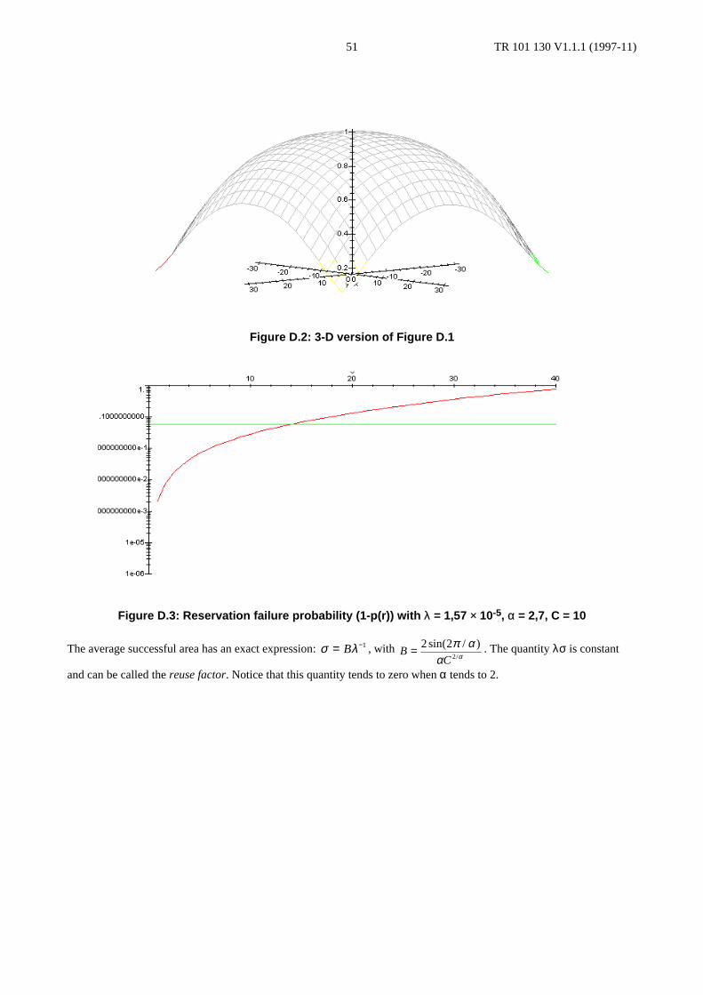
TR 101 130 V1.1.1 (1997-11)51
Figure D.2: 3-D version of Figure D.1
Figure D.3: Reservation failure probability (1-p(r)) with λ = 1,57 × 10⁻⁵, α = 2,7, C = 10
The average successful area has an exact expression: σ λ= −B 1 , with BC
= 2 22
sin( / )/
π αα α
. The quantity λσ is constant
and can be called the reuse factor. Notice that this quantity tends to zero when α tends to 2.
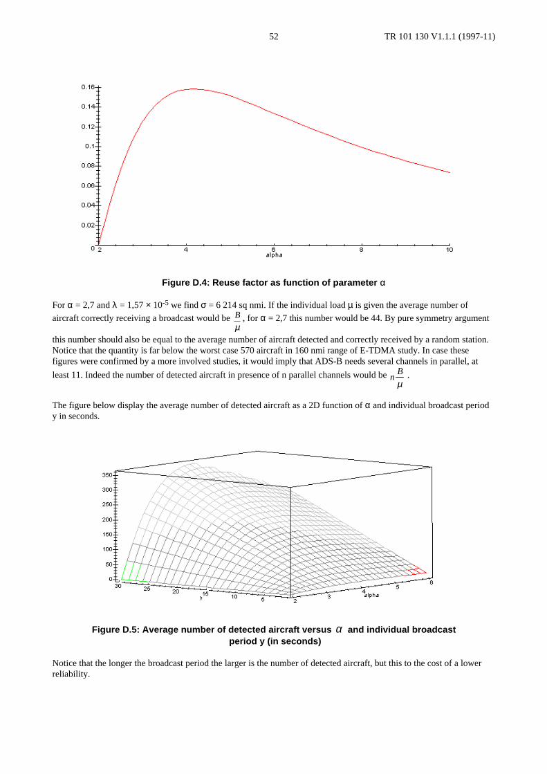
TR 101 130 V1.1.1 (1997-11)52
Figure D.4: Reuse factor as function of parameter α
For α = 2,7 and λ = 1,57 × 10⁻⁵ we find σ = 6 214 sq nmi. If the individual load µ is given the average number of
aircraft correctly receiving a broadcast would be B
µ, for α = 2,7 this number would be 44. By pure symmetry argument
this number should also be equal to the average number of aircraft detected and correctly received by a random station.Notice that the quantity is far below the worst case 570 aircraft in 160 nmi range of E-TDMA study. In case thesefigures were confirmed by a more involved studies, it would imply that ADS-B needs several channels in parallel, at
least 11. Indeed the number of detected aircraft in presence of n parallel channels would be nB
µ .
The figure below display the average number of detected aircraft as a 2D function of α and individual broadcast periody in seconds.
Figure D.5: Average number of detected aircraft versus α and individual broadcast period y (in seconds)
Notice that the longer the broadcast period the larger is the number of detected aircraft, but this to the cost of a lowerreliability.
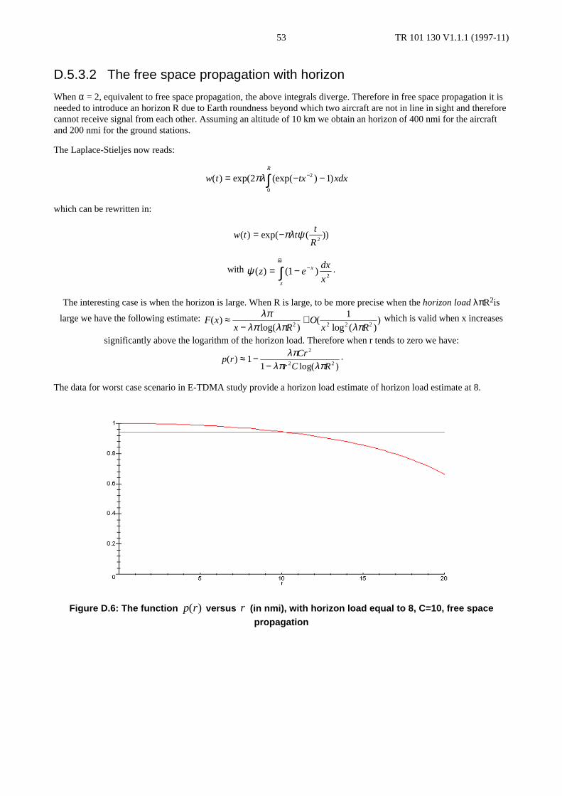
TR 101 130 V1.1.1 (1997-11)53
D.5.3.2 The free space propagation with horizon
When α = 2, equivalent to free space propagation, the above integrals diverge. Therefore in free space propagation it isneeded to introduce an horizon R due to Earth roundness beyond which two aircraft are not in line in sight and thereforecannot receive signal from each other. Assuming an altitude of 10 km we obtain an horizon of 400 nmi for the aircraftand 200 nmi for the ground stations.
The Laplace-Stieljes now reads:
w t tx xdxR
( ) exp( (exp( ) )= − −−∫2 12
0
πλ
which can be rewritten in:
w t tt
R( ) exp( ( ))= −πλ ψ
2
with ψ ( ) ( )z edx
xx
z
= − −+∞
∫ 12
.
The interesting case is when the horizon is large. When R is large, to be more precise when the horizon load λπR2is
large we have the following estimate: F xx R
Ox R
( )log( )
(log ( )
)≈−
+λπλπ λπ λπ2 2 2 2
1 which is valid when x increases
significantly above the logarithm of the horizon load. Therefore when r tends to zero we have:
p rCr
r C R( )
log( )≈ −
−1
1
2
2 2
λπλπ λπ
.
The data for worst case scenario in E-TDMA study provide a horizon load estimate of horizon load estimate at 8.
Figure D.6: The function p r( ) versus r (in nmi), with horizon load equal to 8, C=10, free spacepropagation

TR 101 130 V1.1.1 (1997-11)54
Figure D.7: 3-D version of Figure D.6
Figure D.8: Reservation failure probability (1-p(r)) versus in nmi, with horizon load equal to 8, C=10,free space propagation
Remark the above estimate provides a reliable range of 10 nmi.
The average successful reception area σ has an asymptotic expression which is:
σπ λ λπ λπ
≈ +1 12 2 2C R
ORlog ( )
(log ( )
)
the utilization factor can be derived as well. Notice that the reuse factor does not converge to a constant but decreaseswhen the horizon load increases.
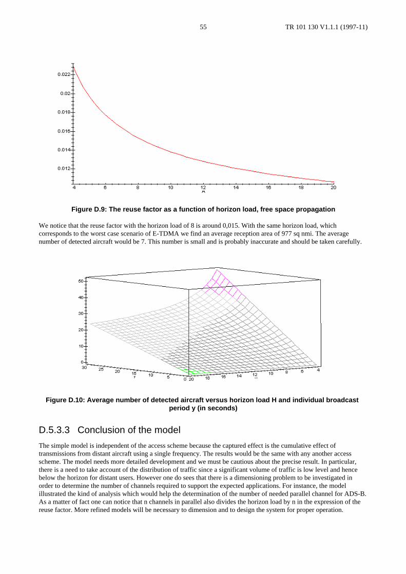
TR 101 130 V1.1.1 (1997-11)55
Figure D.9: The reuse factor as a function of horizon load, free space propagation
We notice that the reuse factor with the horizon load of 8 is around 0,015. With the same horizon load, whichcorresponds to the worst case scenario of E-TDMA we find an average reception area of 977 sq nmi. The averagenumber of detected aircraft would be 7. This number is small and is probably inaccurate and should be taken carefully.
Figure D.10: Average number of detected aircraft versus horizon load H and individual broadcastperiod y (in seconds)
D.5.3.3 Conclusion of the model
The simple model is independent of the access scheme because the captured effect is the cumulative effect oftransmissions from distant aircraft using a single frequency. The results would be the same with any another accessscheme. The model needs more detailed development and we must be cautious about the precise result. In particular,there is a need to take account of the distribution of traffic since a significant volume of traffic is low level and hencebelow the horizon for distant users. However one do sees that there is a dimensioning problem to be investigated inorder to determine the number of channels required to support the expected applications. For instance, the modelillustrated the kind of analysis which would help the determination of the number of needed parallel channel for ADS-B.As a matter of fact one can notice that n channels in parallel also divides the horizon load by n in the expression of thereuse factor. More refined models will be necessary to dimension and to design the system for proper operation.

TR 101 130 V1.1.1 (1997-11)56
D.5.4 The effect and management of remote and hidden terminalsWhen two stations are at distance greater than 300 km (160 nmi), the propagation delays exceed 1 ms and the bursts aremis-synchronized in such a way that they occupy two consecutive slots on the receiver side. Therefore a protocolmalfunction will occur that should be analysed since the load due to remote stations might be not negligible. MaybeD8PSK/GFSK guard times versus received power thresholds could be optimized.
For a system using global channels and providing ADS-B information it is necessary to co-ordinate the access to thechannel so as to prevent some users being unable to receive position information on other users. This "hidden terminal"problem arises when two users broadcast in the same slot with the result that other users receive a transmission fromonly one user, or in the worst extreme, neither user.
In a ground controlled system, it is relatively straightforward to define a co-ordination mechanism to ensure that allusers that can be heard by a ground station can also hear each other. However, this does not ensure that mobiles canreceive other mobiles that are not within reach of the same ground station and hence there is some risk to the integrity ofthe ADS-B air-air application. Note that mobiles are better placed to make decisions on channel usage since they receivetransmissions from the greatest number of transmitters, many of which are not received by the ground station because ofground shielding (which should be investigated in details).
STDMA uses a self-organizing access scheme that combines access control by mobiles with the option of groundcontrol where practical. The scheme has been demonstrated at low traffic levels but will probably require furtherrefinement to deal with higher traffic levels and to achieve high integrity performance. For example the possiblediscrepancies between airborne reservation map and ground station reservation map (leading to hidden nodes cases)could be removed if one allows aircraft to forward their own reservation map to the ground station. Alternatively, anaircraft at higher altitude than the hidden transmitters could notify those of the garbling situation and order some tochange slots.
The hidden node problem depends also of the required Signal over Noise ratio. The larger is the latter the higher will thecollision rates due to hidden nodes. In this perspective D8PSK would perform less than GFSK.
TR 101 130 V1.1.1 (1997-11)57
History
Document history
V1.1.1 November 1997 Publication
ISBN 2-7437-1798-XDépôt légal : Novembre 1997