en 301 199 - v01.01.01 - digital video broadcasting (dvb - etsi
TRANSCRIPT

EN 301 199 V1.1.1 (1998-11)European Standard (Telecommunications series)
Digital Video Broadcasting (DVB);Interaction channel for
Local Multi-point Distribution Systems (LMDS)

ETSI
EN 301 199 V1.1.1 (1998-11)2
ReferenceDEN/JTC-DVB-64 (b3o00ico.PDF)
KeywordsDVB, broadcasting, digital, video, TV
ETSI
Postal addressF-06921 Sophia Antipolis Cedex - FRANCE
Office address650 Route des Lucioles - Sophia Antipolis
Valbonne - FRANCETel.: +33 4 92 94 42 00 Fax: +33 4 93 65 47 16
Siret N° 348 623 562 00017 - NAF 742 CAssociation à but non lucratif enregistrée à laSous-Préfecture de Grasse (06) N° 7803/88
Individual copies of this ETSI deliverablecan be downloaded from
http://www.etsi.org
Copyright Notification
No part may be reproduced except as authorized by written permission.The copyright and the foregoing restriction extend to reproduction in all media.
© European Telecommunications Standards Institute 1998.All rights reserved.

ETSI
EN 301 199 V1.1.1 (1998-11)3
Contents
Intellectual Property Rights................................................................................................................................5
Foreword ............................................................................................................................................................5
1 Scope........................................................................................................................................................6
2 References................................................................................................................................................6
3 Abbreviations ...........................................................................................................................................6
4 Reference model ......................................................................................................................................74.1 Protocol stack model.......................................................................................................................................... 74.2 System model..................................................................................................................................................... 8
5 Interaction channel specification for LMDS networks..........................................................................105.1 System concept ................................................................................................................................................ 105.1.1 Out-of-Band (OOB) / In-Band (IB) principle ............................................................................................ 105.1.2 Intermediate Frequency (IF) spectrum allocation....................................................................................... 115.1.3 FDM/TDMA multiple access..................................................................................................................... 125.1.4 Bit rates and framing .................................................................................................................................. 135.2 Lower physical layer specification................................................................................................................... 135.2.1 Forward Interaction path (downstream OOB)............................................................................................ 155.2.1.1 Frequency range (downstream OOB) ................................................................................................... 155.2.1.2 Modulation and mapping (downstream OOB)...................................................................................... 155.2.1.3 Shaping filter (downstream OOB) ........................................................................................................ 165.2.1.4 Randomizer (downstream OOB) .......................................................................................................... 175.2.1.5 Bit rate (downstream OOB).................................................................................................................. 185.2.1.6 Receiver power level (downstream OOB) ............................................................................................ 185.2.1.7 Summary (downstream OOB) .............................................................................................................. 195.2.1.8 Bit error rate downstream OOB (informative)...................................................................................... 215.2.2 Forward Interaction path (downstream IB) ................................................................................................ 215.2.3 Return Interaction path (upstream)............................................................................................................. 215.2.3.1 IF range (upstream) .............................................................................................................................. 215.2.3.2 Modulation and mapping (upstream).................................................................................................... 215.2.3.3 Shaping filter (upstream) ...................................................................................................................... 225.2.3.4 Randomizer (upstream) ........................................................................................................................ 235.2.3.5 Bit rate (upstream)................................................................................................................................ 235.2.3.6 Transmit power level (upstream) .......................................................................................................... 235.2.3.7 Carrier suppression when idle (upstream) ............................................................................................ 235.2.3.8 Summary (upstream)............................................................................................................................. 245.3 Framing............................................................................................................................................................ 255.3.1 Forward Interaction path (downstream OOB)............................................................................................ 255.3.1.1 Signalling Link Extended Superframe (SL-ESF) framing format......................................................... 255.3.1.2 Frame overhead .................................................................................................................................... 265.3.1.3 Payload structure .................................................................................................................................. 275.3.2 Forward interaction path (downstream IB)................................................................................................. 325.3.3 Return interaction path (upstream)............................................................................................................. 345.3.3.1 Slot format ............................................................................................................................................ 345.4 Slot timing assignment..................................................................................................................................... 355.4.1 Downstream slot position reference (downstream OOB) ........................................................................... 355.4.2 Downstream slot position reference (downstream IB) ............................................................................... 365.4.3 Upstream slot positions .............................................................................................................................. 375.4.4 Slot position counter .................................................................................................................................. 385.5 MAC functionality ........................................................................................................................................... 395.5.1 MAC reference model ................................................................................................................................ 395.5.2 MAC concept ............................................................................................................................................. 405.5.2.1 Relationship between higher layers and MAC protocol ....................................................................... 405.5.2.2 Relationship between physical layer and MAC protocol ...................................................................... 41

ETSI
EN 301 199 V1.1.1 (1998-11)4
5.5.2.3 Relationship between physical layer slot position counter and MAC slot assignment.......................... 415.5.2.4 Access modes (contention/ranging/fixed rate/reservation) ................................................................... 415.5.2.5 MAC error handling procedures........................................................................................................... 425.5.2.6 MAC messages ..................................................................................................................................... 425.5.3 MAC initialization and provisioning.......................................................................................................... 455.5.3.1 <MAC> Provisioning channel message (Broadcast downstream)........................................................ 465.5.3.2 <MAC> Default configuration message (Broadcast downstream) ....................................................... 465.5.4 Sign-On and Calibration............................................................................................................................. 485.5.4.1 <MAC> Sign-On Request message (Broadcast downstream) .............................................................. 505.5.4.2 <MAC> Sign-On Response Message (Upstream Contention Ranging) ............................................... 515.5.4.3 <MAC> Range and Power Calibration Message (Singlecast downstream).......................................... 515.5.4.4 <MAC> Ranging and Power Calibration Response Message (Upstream reserved or contention
Ranging) ............................................................................................................................................... 525.5.4.5 <MAC> Initialization complete message (singlecast downstream) ...................................................... 535.5.5 Default connection establishment............................................................................................................... 535.5.5.1 <MAC> Connect message (Singlecast downstream)............................................................................ 545.5.5.2 <MAC> Connect response (upstream contention, reserved or fixed rate access)................................. 575.5.5.3 <MAC> Connect confirm (singlecast downstream) ............................................................................. 585.5.6 Data connections ........................................................................................................................................ 585.5.6.1 Fixed rate access................................................................................................................................... 595.5.6.2 Contention based access ....................................................................................................................... 595.5.6.3 Reservation access................................................................................................................................ 595.5.7 MAC link management .............................................................................................................................. 635.5.7.1 Power and timing management............................................................................................................. 635.5.7.2 TDMA allocation management............................................................................................................. 635.5.7.3 Channel error management ................................................................................................................... 665.5.7.4 Link management messages.................................................................................................................. 66
Bibliography.....................................................................................................................................................72
History..............................................................................................................................................................73

ETSI
EN 301 199 V1.1.1 (1998-11)5
Intellectual Property RightsIPRs essential or potentially essential to the present document may have been declared to ETSI. The informationpertaining to these essential IPRs, if any, is publicly available for ETSI members and non-members, and can be foundin SR 000 314: "Intellectual Property Rights (IPRs); Essential, or potentially Essential, IPRs notified to ETSI in respectof ETSI standards", which is available free of charge from the ETSI Secretariat. Latest updates are available on theETSI Web server (http://www.etsi.org/ipr).
Pursuant to the ETSI IPR Policy, no investigation, including IPR searches, has been carried out by ETSI. No guaranteecan be given as to the existence of other IPRs not referenced in SR 000 314 (or the updates on the ETSI Web server)which are, or may be, or may become, essential to the present document.
ForewordThis European Standard (Telecommunications series) has been produced by the Joint Technical Committee (JTC)Broadcast of the European Broadcasting Union (EBU), Comité Européen de Normalisation ELECtrotechnique(CENELEC) and the European Telecommunications Standards Institute (ETSI).
NOTE: The EBU/ETSI JTC Broadcast was established in 1990 to co-ordinate the drafting of standards in thespecific field of broadcasting and related fields. Since 1995 the JTC Broadcast became a tripartite bodyby including in the Memorandum of Understanding also CENELEC, which is responsible for thestandardization of radio and television receivers. The EBU is a professional association of broadcastingorganizations whose work includes the co-ordination of its members' activities in the technical, legal,programme-making and programme-exchange domains. The EBU has active members in about 60countries in the European broadcasting area; its headquarters is in Geneva.
European Broadcasting UnionCH-1218 GRAND SACONNEX (Geneva)SwitzerlandTel: +41 22 717 21 11Fax: +41 22 717 24 81
Digital Video Broadcasting (DVB) Project
Founded in September 1993, the DVB Project is a market-led consortium of public and private sector organizations inthe television industry. Its aim is to establish the framework for the introduction of MPEG-2 based digital televisionservices. Now comprising over 200 organizations from more than 25 countries around the world, DVB fostersmarket-led systems, which meet the real needs, and economic circumstances, of the consumer electronics and thebroadcast industry.
National transposition dates
Date of adoption of this EN: 18 September 1998
Date of latest announcement of this EN (doa): 31 December 1998
Date of latest publication of new National Standardor endorsement of this EN (dop/e): 30 June 1999
Date of withdrawal of any conflicting National Standard (dow): 30 June 1999

ETSI
EN 301 199 V1.1.1 (1998-11)6
1 ScopeThe present document is the baseline specification for the provision of interaction channel for Local Multi-pointDistribution Systems (LMDS) networks.
It is not intended to specify a return channel solution associated to each broadcast system because the inter-operability ofdifferent delivery media to transport the return channel is desirable.
The solutions provided in the present document for interaction channel for LMDS networks are a part of a wider set ofalternatives to implement interactive services for Digital Video Broadcasting (DVB) systems.
2 ReferencesThe following documents contain provisions which, through reference in this text, constitute provisions of the presentdocument.
• References are either specific (identified by date of publication, edition number, version number, etc.) ornon-specific.
• For a specific reference, subsequent revisions do not apply.
• For a non-specific reference, subsequent revisions do apply.
• A non-specific reference to an ETS shall also be taken to refer to later versions published as an EN with the samenumber.
[1] ETS 300 800: "Digital Video Broadcasting (DVB); Interaction channel for Cable TV distributionsystems (CATV)".
[2] ISO 13818-1: "Information technology - Generic coding of moving pictures and associated audioinformation - Systems".
[3] ETS 300 802: "Digital Video Broadcasting (DVB); Network-independent protocols for DVBinteractive services".
[4] EN 300 421: "Digital Video Broadcasting (DVB); Framing structure, channel coding andmodulation for 11/12 GHz satellite services".
[5] ITU-T Recommendation I.361: "B-ISDN ATM layer specification".
[6] ITU-T Recommendation I.363: "B-ISDN ATM Adaptation Layer (AAL) specification".
3 AbbreviationsFor the purposes of the present document, the following abbreviations apply:
AAL5 ATM Adaptation Layer 5ATM Asynchronous Transfer ModeBC Broadcast ChannelBIM Broadcast Interface ModuleBW BandWidthCRC Cyclic Redundancy CheckDAVIC Digital Audio - Visual CouncilDL Data LinkDVB Digital Video BroadcastingDVB-MS DVB - Microwave SatelliteFAS Frame Alignment SignalFDM Frequency Division Multiplex

ETSI
EN 301 199 V1.1.1 (1998-11)7
FEC Forward Error CorrectionFIFO First In First OutFIP Forward Interaction PathIB In-BandID IDentifierIEEE Institute of Electrical and Electronics Engineers (USA)IF Intermediate FrequencyIIM Interactive Interface ModuleINA Interactive Network AdapterIRD Integrated Receiver DecoderISDN Integrated Services Digital NetworkLFSR Linear Feedback Shift RegisterLMDS Local Multi-point Distribution SystemsMAC Media Access ControlMPEG Moving Picture Export GroupMS Microwave SatelliteMSB Most Significant BitNIU Network Interface UnitOH OverHeadOOB Out-Of-BandOSI Open Systems InterconnectionPID Packet IDendifierPM Phase ModulationPSK Phase Shift KeyingPSTN Public Switched Telephone NetworkQPSK Quaternary Phase Shift KeyingRF Radio FrequencyRIP Return Interaction PathRMS Root Mean SquareRS Reed SolomonSL-ESF Signalling Link Extended SuperframeSTB Set Top BoxSTU Set Top UnitTCP Transmission Control ProtocolTDMA Time Division Multiple AccessTS Transport StreamVCI Virtual Channel IdentifierVPI Virtual Path Identifier
4 Reference modelThis clause presents the reference model for system architecture of narrow-band interaction channels in a broadcastingscenario (asymmetric interactive services).
4.1 Protocol stack modelFor asymmetric interactive services supporting broadcast to the home with narrowband return channel, a simplecommunications model consists of the following layers:
- Physical layer: where all the physical (electrical) transmission parameters are defined.
- Transport layer: defines all the relevant data structures and communication protocols like data containers, etc.
- Application layer: is the interactive application software and runtime environments (e.g. home shoppingapplication, script interpreter, etc.).
The present document addresses the lower two layers (the physical and transport) leaving the application layer open tocompetitive market forces.

ETSI
EN 301 199 V1.1.1 (1998-11)8
A simplified model of the OSI layers was adopted to facilitate the production of specifications for these nodes. Figure 1points out the lower layers of the simplified model and identifies some of the key parameters for the lower two layers.Following the user requirements for interactive services, no attempt will be made to consider higher layers in the presentdocument.
Layer Structure for Generic System Reference Model
Modulat ionChannel coding
Freq. rangeFiltering
Equal isat ionPower
Accessmechan ism
Packet structure
Higher medium layers
Proprietarylayers
(Network Dependent
Protocols)
Network Independent
Protocols
Figure 1: Layer structure for generic system reference model
The present document addresses the PSTN/ISDN network specific aspects only. The network independent protocols willbe specified separately.
4.2 System modelFigure 2 shows the system model which is to be used within DVB for interactive services.
In the system model, two channels are established between the service provider and the user:
- Broadcast Channel (BC): a unidirectional broadband BC including video, audio and data. BC is establishedfrom the service provider to the users. It may include the Forward Interaction path.
- Interaction channel: a bi-directional interaction channel is established between the service provider and the userfor interaction purposes. It is formed by:
- Return interaction path (return channel): from the user to the service provider. It is used to make requeststo the service provider or to answer questions. It is a narrowband channel. Also commonly known as returnchannel.
- Forward interaction path: from the service provider to the user. It is used to provide some sort ofinformation by the service provider to the user and any other required communication for the interactiveservice provision. It may be embedded into the BC. It is possible that this channel is not required in somesimple implementations which make use of the BC for the carriage of data to the user.
The user terminal is formed by the Network Interface Unit (NIU) (consisting of the Broadcast Interface Module (BIM)and the Interactive Interface Module (IIM)) and the Set Top Unit (STU). The user terminal provides interface for bothbroadcast and interaction channels. The interface between the user terminal and the interaction network is via the IIM.

ETSI
EN 301 199 V1.1.1 (1998-11)9
Figure 2A: Generic system reference model for interactive systems

ETSI
EN 301 199 V1.1.1 (1998-11)10
RF/IF NIU STURF/IFINA
ON AIRTransmission
RF referencepoint
RF referencepoint
IF referencepoint
IF referencepoint
Figure 2B: Position of IF and RF reference points in the particular case of LMDS networks
5 Interaction channel specification for LMDS networksThe LMDS infrastructures can support the implementation of the return channel for interactive services suitable forDVB broadcasting systems.
LMDS can be used to implement interactive services in the DVB environment, providing a bi-directionalcommunication path between the user terminal and the service provider.
5.1 System conceptThe interactive system is composed of Forward Interaction path (downstream) and Return Interaction path (upstream).The general concept is to use downstream transmission from the INA to the NIUs to provide synchronization andinformation to all NIUs. This allows the NIUs to adapt to the network and send synchronies information upstream.
Upstream transmission is divided into time slots which can be used by different users, using the technique of TimeDivision Multiple Access (TDMA). One downstream channel is used to synchronies up to 8 upstream channels, whichare all divided into time slots. A counter at the INA is sent periodically to the NIUs, so that all NIUs work with the sameclock. This gives the opportunity to the INA to assign time slots to different users.
Three major access modes are provided with this system. The first one is based on contention access, which lets userssend information at any time with the risk to have a collision with other user's transmissions. The second and thirdmodes are contention-less based, where the INA either provides a finite amount of slots to a specific NIU, or a given bitrate requested by a NIU until the INA stops the connection on NIUs demand. These access modes are dynamicallyshared among time slots, which allows NIUs to know when contention based transmission is or is not allowed. This is toavoid a collision for the two contention-less based access modes.
Periodically, the INA will indicate to new users that they have the possibility to go through Sign-On procedure, in orderto give them the opportunity to synchronies their clock to the network clock, without risking collisions with alreadyactive users. This is done by leaving a larger time interval for new users to send their information, taking into accountthe propagation time required from the INA to the NIUs and back.
5.1.1 Out-of-Band (OOB) / In-Band (IB) principle
This interactive system is based either on OOB or IB downstream signalling. However, STBs do not need to supportboth systems.
In the case of OOB signalling, a Forward Interaction path is added. This path is reserved for interactivity data andcontrol information only. The presence of this added Forward Information path is in that case mandatory. However, it isalso possible to send higher bit rate downstream information through a DVB-MS channel whose frequency is indicatedin the forward information path.
ETSI
EN 301 199 V1.1.1 (1998-11)11
In the case of IB signalling, the Forward Information path is embedded into the MPEG2-TS of a DVB-MS channel. It isnot mandatory to include the Forward Information path in all DVB-MS channels.
Both systems can provide the same quality of service. However, the overall system architecture will differ betweennetworks using IB and OOB STBs. Both types of systems may exist on the same networks under the condition thatdifferent frequencies are used for each system.
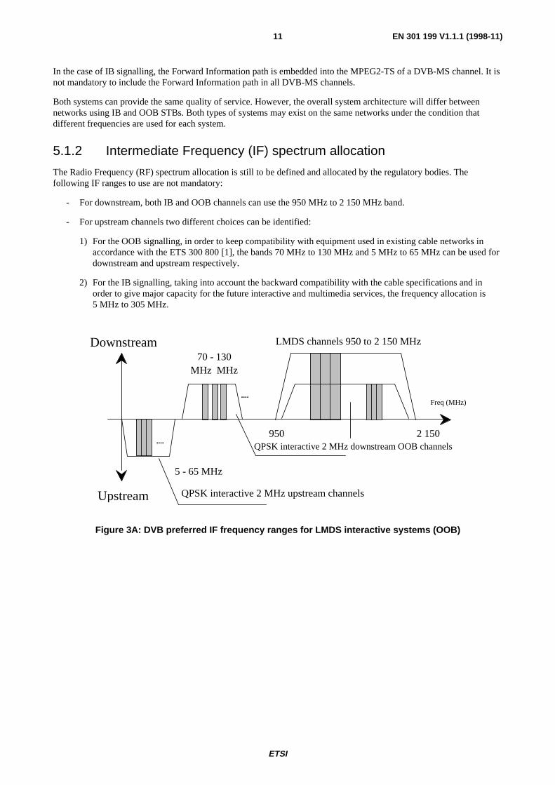
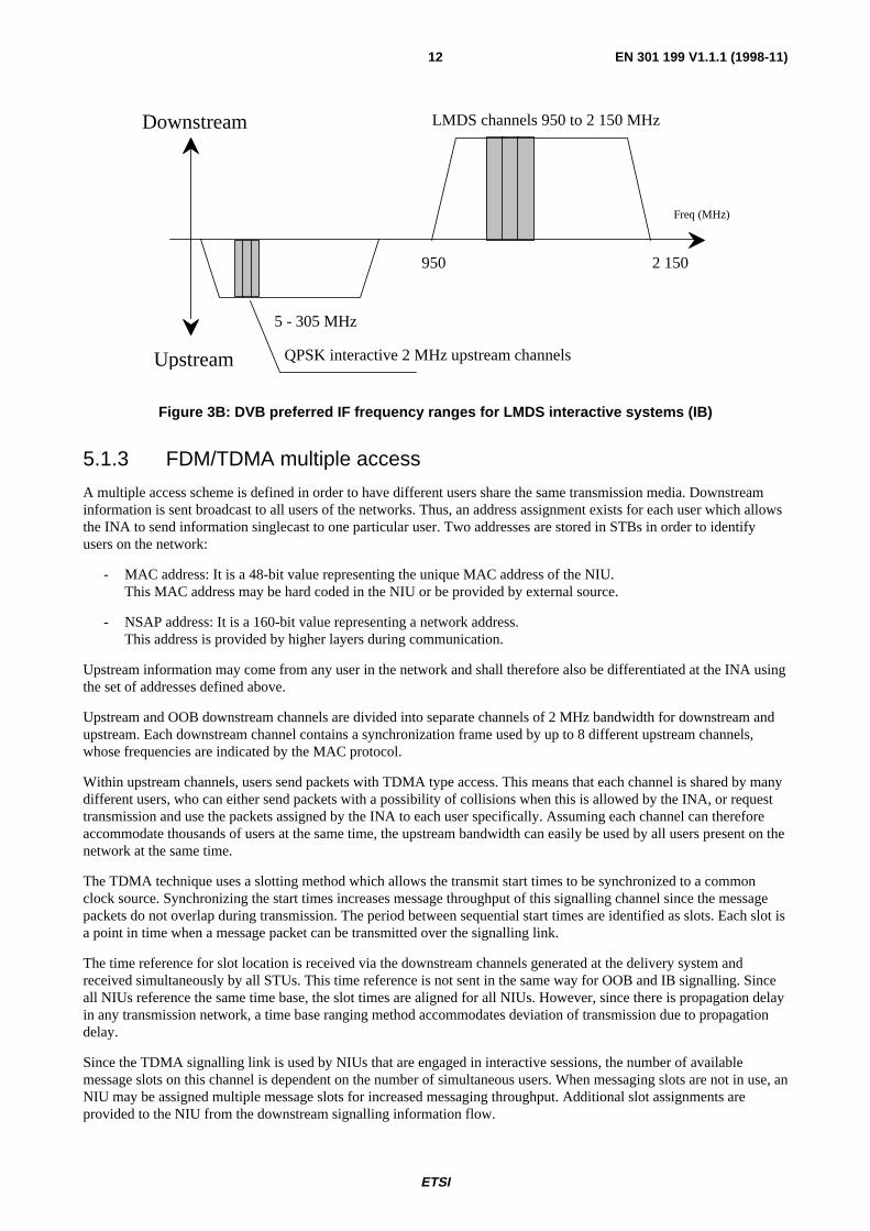
5.1.2 Intermediate Frequency (IF) spectrum allocation
The Radio Frequency (RF) spectrum allocation is still to be defined and allocated by the regulatory bodies. Thefollowing IF ranges to use are not mandatory:
- For downstream, both IB and OOB channels can use the 950 MHz to 2 150 MHz band.
- For upstream channels two different choices can be identified:
1) For the OOB signalling, in order to keep compatibility with equipment used in existing cable networks inaccordance with the ETS 300 800 [1], the bands 70 MHz to 130 MHz and 5 MHz to 65 MHz can be used fordownstream and upstream respectively.
2) For the IB signalling, taking into account the backward compatibility with the cable specifications and inorder to give major capacity for the future interactive and multimedia services, the frequency allocation is5 MHz to 305 MHz.
QPSK interactive 2 MHz downstream OOB channels
Freq (MHz)
Downstream
Upstream
....
....
QPSK interactive 2 MHz upstream channels
2 150
LMDS channels 950 to 2 150 MHz
70 - 130MHz MHz
5 - 65 MHz
950
Figure 3A: DVB preferred IF frequency ranges for LMDS interactive systems (OOB)
ETSI
EN 301 199 V1.1.1 (1998-11)12
Freq (MHz)
Downstream
Upstream QPSK interactive 2 MHz upstream channels
2 150
LMDS channels 950 to 2 150 MHz
5 - 305 MHz
950
Figure 3B: DVB preferred IF frequency ranges for LMDS interactive systems (IB)
5.1.3 FDM/TDMA multiple access
A multiple access scheme is defined in order to have different users share the same transmission media. Downstreaminformation is sent broadcast to all users of the networks. Thus, an address assignment exists for each user which allowsthe INA to send information singlecast to one particular user. Two addresses are stored in STBs in order to identifyusers on the network:
- MAC address: It is a 48-bit value representing the unique MAC address of the NIU.This MAC address may be hard coded in the NIU or be provided by external source.
- NSAP address: It is a 160-bit value representing a network address.This address is provided by higher layers during communication.
Upstream information may come from any user in the network and shall therefore also be differentiated at the INA usingthe set of addresses defined above.
Upstream and OOB downstream channels are divided into separate channels of 2 MHz bandwidth for downstream andupstream. Each downstream channel contains a synchronization frame used by up to 8 different upstream channels,whose frequencies are indicated by the MAC protocol.
Within upstream channels, users send packets with TDMA type access. This means that each channel is shared by manydifferent users, who can either send packets with a possibility of collisions when this is allowed by the INA, or requesttransmission and use the packets assigned by the INA to each user specifically. Assuming each channel can thereforeaccommodate thousands of users at the same time, the upstream bandwidth can easily be used by all users present on thenetwork at the same time.
The TDMA technique uses a slotting method which allows the transmit start times to be synchronized to a commonclock source. Synchronizing the start times increases message throughput of this signalling channel since the messagepackets do not overlap during transmission. The period between sequential start times are identified as slots. Each slot isa point in time when a message packet can be transmitted over the signalling link.
The time reference for slot location is received via the downstream channels generated at the delivery system andreceived simultaneously by all STUs. This time reference is not sent in the same way for OOB and IB signalling. Sinceall NIUs reference the same time base, the slot times are aligned for all NIUs. However, since there is propagation delayin any transmission network, a time base ranging method accommodates deviation of transmission due to propagationdelay.
Since the TDMA signalling link is used by NIUs that are engaged in interactive sessions, the number of availablemessage slots on this channel is dependent on the number of simultaneous users. When messaging slots are not in use, anNIU may be assigned multiple message slots for increased messaging throughput. Additional slot assignments areprovided to the NIU from the downstream signalling information flow.
ETSI
EN 301 199 V1.1.1 (1998-11)13
There are different access modes for the upstream slots:
- reserved slots with fixed rate reservation (Fixed rate access: the user has a reservation of one or several time slotsin each frame enabling, e.g. for voice, audio);
- reserved slots with dynamic reservation (Reservation access: the user sends control information announcing hisdemand for transmission capacity. He gets grants for the use of slots);
- contention based slots (These slots are accessible for every user. Collision is possible and solved by a contentionresolution protocol);
- ranging slots (these slots are used upstream to measure and adjust the time delay and the power).
These slots may be mixed on a single carrier to enable different services on one carrier only. If one carrier is assigned toone specific service, only those slot types will be used which are needed for this service. Therefore a terminal can besimplified to respond to only those slot types assigned to the service.
5.1.4 Bit rates and framing
For the interactive downstream OOB channel, a rate of 3,088 Mbit/s may be used. For downstream IB channels, noother constraints than those specified in the DVB-MS specifications exist, but a guideline would be to use ratesmultiples of 8 kbit/s.
Downstream OOB channels continuously transmit a frame based on T1 type framing, in which some information isprovided for synchronization of upstream slots. Downstream IB channels transmit some MPEG2-TS packets with aspecific PID for synchronization of upstream slots (at least one packet containing synchronization information shall besent in every period of 3 ms).
Upstream framing consists of packets of 512 bits (256 symbols) which are sent in a bursty mode from the different userspresent on the network. The upstream slot rates are 6 000 upstream slots/s.
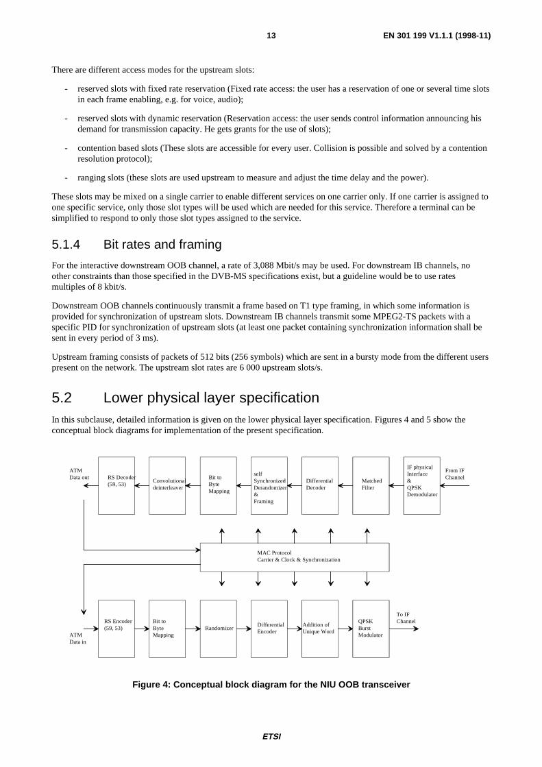
5.2 Lower physical layer specificationIn this subclause, detailed information is given on the lower physical layer specification. Figures 4 and 5 show theconceptual block diagrams for implementation of the present specification.
From IFChannel
IF physicalInterface&QPSKDemodulator
MatchedFilter
Differential Decoder
selfSynchronizedDerandomizer&Framing
Bit toByteMapping
Convolutionaldeinterleaver
RS Decoder(59, 53)
MAC ProtocolCarrier & Clock & Synchronization
ATMData out
ATMData in
RS Encoder(59, 53)
Bit toByteMapping
RandomizerDifferentialEncoder
Addition of Unique Word
QPSKBurstModulator
To IFChannel
Figure 4: Conceptual block diagram for the NIU OOB transceiver
ETSI
EN 301 199 V1.1.1 (1998-11)14
BBPhysicalInterface
ReedSolomonEncoder
Co
nvo
lutio
na
lIn
terl
ea
ver
Fra
min
g
Byte toBitMapping
Ra
nd
om
ize
r
Diff
ere
ntia
lE
nco
de
r
QP
SK
Mo
du
lato
r
To IFChannel
MAC Protocol managementcarrier & Clock & Synchronization Generator
DataATMin
Baseband interface to :Service provider sourceMultiplexers, etc.
DataATMout
RS Decoder(59, 53)
Bit toBytemapping
DerandomizerDifferentialencoder
QPSK burstDémodulator
From IFChannel
LMDS Head-end
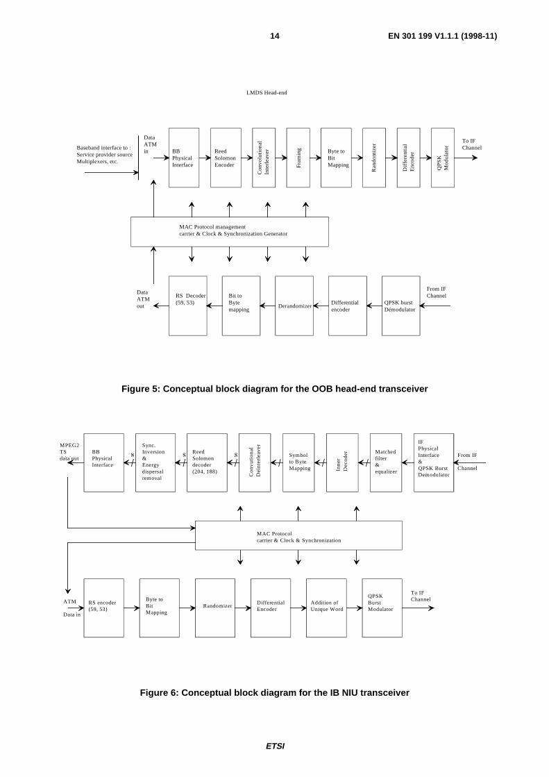
Figure 5: Conceptual block diagram for the OOB head-end transceiver
IFPhysicalInterface&QPSK BurstDemodulator
Matchedfilter&equalizerIn
ne
rD
eco
de
r
Symbolto ByteMapping
Co
nvu
tion
al
De
inte
rle
ave
r
ReedSolomondecoder(204, 188)
Sync.Inversion&Energydispersalremoval
BBPhysicalInterface
RS encoder(59, 53)
Byte toBitMapping
RandomizerDifferentialEncoder
Addition ofUnique Word
QPSKBurstModulator
To IFChannel
MAC Protocolcarrier & Clock & Synchronization
MPEG2TSdata out
ATM
Data in
From IF
Channel
Figure 6: Conceptual block diagram for the IB NIU transceiver

ETSI
EN 301 199 V1.1.1 (1998-11)15
QP
SK
Mo
du
lato
r&
IF P
hys
ica
l in
terf
ace
Inner coder
Puncturing& Mapping
RS encoder(204, 188)
BB
sh
apin
g
Co
nvo
lutio
na
lIn
terl
ea
ver
I= 1
2 B
yte
s
Syn
c in
vers
ion
&E
ne
rgy
dis
pe
rsa
l
BB
Ph
ysic
al
Inte
rfa
ce
MPEG2 - TSData in
MAC Protocol ManagementCarrier & Clock & Synchronisation
Baseband Interface to :Service Provider sourceMultiplexer, etc.
RS Decoder(59, 53) Bit to
Byte MappingDerandomizer
DifferentialDecoder
QPSKBurst
demodulator
ATM
data out
FromIF Channel
To IFChannel
Figure 7: Conceptual block diagram for the IB head-end transceiver
5.2.1 Forward Interaction path (downstream OOB)
5.2.1.1 Frequency range (downstream OOB)
See subclause 5.1.2.
5.2.1.2 Modulation and mapping (downstream OOB)
QPSK modulation is used as a means of encoding digital information over wireless or wireline transmission links. Themethod is a subset of Phase Shift Keying (PSK) which is a subset of Phase Modulation (PM). Specifically QPSK is afour level use of digital PM. Quadrature signal representations involve expressing an arbitrary phase sinusoidalwaveform as a linear combination of a cosine wave and a sine wave with zero starting phases.
QPSK systems require the use of differential encoding and corresponding differential detection. This is a result of thereceivers having no method of determining if a recovered reference is a sine reference or a cosine reference. In addition,the polarity of the recovered reference is uncertain.
Differential encoding transmits the information in encoded phase differences between the two successive signals.The modulator processes the digital binary symbols to achieve differential encoding and then transmits the absolutephases.
The differential encoding is implemented at the digital level.

ETSI
EN 301 199 V1.1.1 (1998-11)16
The differential encoder shall accept bits A, B in sequence, and generate phase changes as follows:
Table 1: Phase changes associated with bit A, B
A B Phase Change0 0 none0 1 +90°1 1 180°1 0 -90°
In serial mode, A arrives first. The outputs I, Q from the differential encoder map to the phase states as in figure 8.
I
Q
1101
1000
Figure 8: Mapping for the QPSK constellation (downstream OOB)
The phase changes can also be expressed by the following formulas (assuming the constellation is mapped from I and Qas shown in subclause 5.2.2.2):
A I Q Q Q I Q I I
B I Q I I I Q Q Qk k k k k k k k k
k k k k k k k k k
= ⊕ × ⊕ + ⊕ × ⊕= ⊕ × ⊕ + ⊕ × ⊕
− − − − −
− − − − −
( ) ( ) ( ) ( )
( ) ( ) ( ) ( )1 1 1 1 1
1 1 1 1 1,
where k is the time index.
I/Q amplitude imbalance shall be less than 1,0 dB, and phase imbalance less than 2,0°.
5.2.1.3 Shaping filter (downstream OOB)
The time-domain response of a square-root raised-cosine pulse with excess bandwidth parameter α is given by:
g t
tT
tT
tT
t
T
t
T
( )sin[ ( )] cos[ ( )]
[ ( ) ]=
− + +
−
π α α π α
π α
14
1
14 2
where T is the symbol period.
The output signal shall be defined as
S t I g t nT f t Q g t nT f tn c nn
c( ) [ ( ) cos( ) ( ) sin( )]= × − × −∑ × − ×2 2π π
with In and Qn equal to ± 1, independently from each other, and fc the QPSK modulator's carrier frequency.
The QPSK modulator divides the incoming bit stream so that bits are sent alternately to the in-phase modulator I and theout-of-phase modulator Q. These same bit streams appear at the output of the respective phase detectors in thedemodulator where they are interleaved back into a serial bit stream.

ETSI
EN 301 199 V1.1.1 (1998-11)17
The occupied bandwidth of a QPSK signal is given by the equation:
Bandwidth = f b
2 (1 + α )
fb = bit rate
α = excess bandwidth = 0,30
The spectral mask is the following:
Table 2: Spectral mask for QPSK modulated signal
BW (MHz) Response (dB)1 0 ± 0,25
1,544 -3 ± 0,252,0 -24 ± 3
2,16 < -363,08 < -403,6 < -50
Carrier suppression shall be greater than 30 dB.
5.2.1.4 Randomizer (downstream OOB)
After addition of the Forward Error Correction (FEC) bytes (see subclause 5.3), all of the 3,088 Mbit/s data is passedthrough a six register Linear Feedback Shift Register (LFSR) randomizer to ensure a random distribution of ones andzeroes.The generating polynomial is:
x x6 5 1+ + .
Byte/serial conversion shall be MSB first. A complementary self-synchronizing de-randomizer is used in the receiver torecover the data.
Serial Output
Serial Input
Figure 9: Randomizer

ETSI
EN 301 199 V1.1.1 (1998-11)18
Serial Input
Serial output
Figure 10: De-randomizer
5.2.1.5 Bit rate (downstream OOB)
The bit rate shall be 3,088 Mbit/s. Symbol rate accuracy should be within ± 50 ppm.
5.2.1.6 Receiver power level (downstream OOB)
The receiver power level shall be in the range 42 dBµV to 75 dBµV (RMS) (75 Ω) at the IF input point.

ETSI
EN 301 199 V1.1.1 (1998-11)19
5.2.1.7 Summary (downstream OOB)
Table 3: Summary (downstream)
Summary (downstream)Transmission rate 3,088 Mbit/sModulation Differentially encoded QPSK.Transmit filtering Filtering is α = 0,30 square root raised cosineChannel spacing 2 MHzFrequency step size 250 kHz (centre frequency granularity)Randomization After addition of the FEC bytes, all of the 3,088 Mbit/s data is passed through
a six register Linear Feedback Shift Register (LFSR) randomizer to ensure arandom distribution of ones and zeroes. The generating polynomial is:
x x6 5 1+ + .Byte/serial conversion shall be MSB first.A complementary self-synchronizing de-randomizer is used in the receiver torecover the data.
Differential encoding The differential encoder shall accept bits A, B in sequence, and generatephase changes as follows:
A B Phase change0 0 none0 1 +90°1 1 180°1 0 -90°
In serial mode, A arrives first.System phase noise max.:(phase noise includesboth IF and RF parts).
-41 dBc/Hz at 1 kHz-71 dBc/Hz at 10 kHz-92 dBc/Hz at 100 kHz
Signal constellation The outputs I, Q from the differential encoder map to the phase states as infigure 11.
I
Q
1101
1000
Figure 11
IF range (not mandatory) 950 - 2 150 MHz or 70 - 130 MHzFrequency stability ± 50 ppm measured at the upper limit of the IF rangeSymbol rate accuracy ± 50 ppmCarrier suppression > 30 dBI/Q amplitude imbalance < 1,0 dBI/Q phase imbalance < 2,0°Receive power level at IFreference point(downstream out-of-band)
42 - 75 dBµV (RMS) (75 Ω)

ETSI
EN 301 199 V1.1.1 (1998-11)20
Summary (downstream)Transmit spectral mask Bit rate = 3,088 Mbit/s
BW (MHz) Response (dB)1,0 0 ± 0,251,544 -3 ± 0,252,0 < -24 ± 32,16 < -363,088 < -40
0 dB rm
rN
Frequency MHz
H(f)
-3 dB
in-band ripple < 0,5 dBrm
out-of-bandrejection
> 40 dB
-24 dB
1,5441,0
rN < 0,5 dB
-40 dB
2,0 2,16
-36 dB
3,08
0 dB rm
rN
Frequency MHz
H(f)
-3 dB
in-band ripple < 0,5 dBrm
out-of-bandrejection
> 40 dB
-24 dB
1,5441,0
rN < 0,5 dB
-40 dB
2,0 2,16
-36 dB
3,08
0 dB rm
rN
Frequency MHz
H(f)
-3 dB
in-band ripple < 0,5 dBrm
out-of-bandrejection
> 40 dB
-24 dB
1,5441,0
rN < 0,5 dB
-40 dB
2,0 2,16
-36 dB
3,08
ETSI
EN 301 199 V1.1.1 (1998-11)21
5.2.1.8 Bit error rate downstream OOB (informative)
To be confirmed.
5.2.2 Forward Interaction path (downstream IB)
The IB Forward Interaction path shall use a MPEG2-TS stream with a modulated QPSK channel as defined inEN 300 421 [4]. Frequency range, channel spacing, and other lower physical layer parameters should followEN 300 421 [4].
5.2.3 Return Interaction path (upstream)
5.2.3.1 IF range (upstream)
The frequency range is not specified as mandatory although a guideline is provided to use the 5 to 65 MHz range.Frequency stability shall be in the range ± 50 ppm measured at the upper limit of the frequency range.
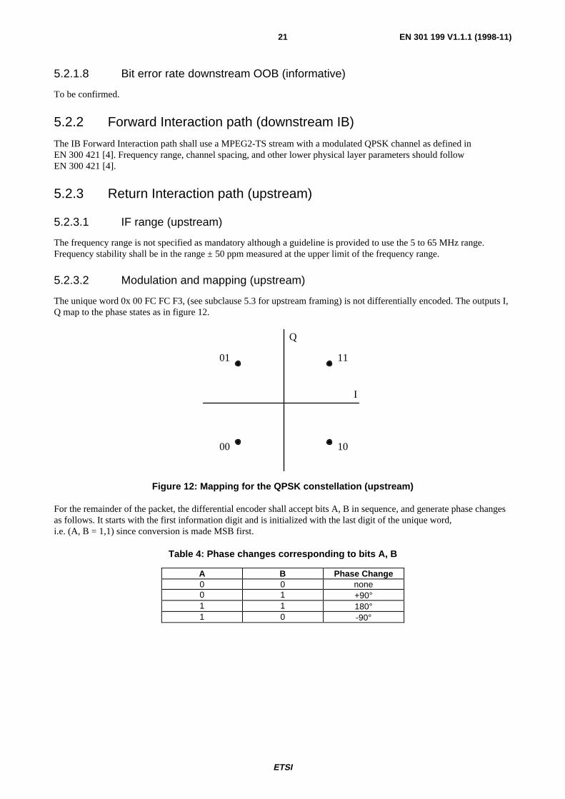
5.2.3.2 Modulation and mapping (upstream)
The unique word 0x 00 FC FC F3, (see subclause 5.3 for upstream framing) is not differentially encoded. The outputs I,Q map to the phase states as in figure 12.
I
Q
1101
1000
Figure 12: Mapping for the QPSK constellation (upstream)
For the remainder of the packet, the differential encoder shall accept bits A, B in sequence, and generate phase changesas follows. It starts with the first information digit and is initialized with the last digit of the unique word,i.e. (A, B = 1,1) since conversion is made MSB first.
Table 4: Phase changes corresponding to bits A, B
A B Phase Change0 0 none0 1 +90°1 1 180°1 0 -90°

ETSI
EN 301 199 V1.1.1 (1998-11)22
Phase changes correspond to the following formulas (assuming I and Q are mapped to the constellation as for the uniqueword):
A I Q Q Q I Q I I
B I Q I I I Q Q Qk k k k k k k k k
k k k k k k k k k
= ⊕ × ⊕ + ⊕ × ⊕= ⊕ × ⊕ + ⊕ × ⊕
− − − − −
− − − − −
( ) ( ) ( ) ( )
( ) ( ) ( ) ( )1 1 1 1 1
1 1 1 1 1,
where k is the time index.
I/Q amplitude imbalance shall be less than 1,0 dB, and phase imbalance less than 2,0°.
5.2.3.3 Shaping filter (upstream)
The time-domain response of a square-root raised-cosine pulse with excess bandwidth parameter α is given by:
g t
t
T
t
T
t
Tt
T
t
T
( )sin[ ( )] cos[ ( )]
[ ( ) ]=
− + +
−
π α α π α
π α
14
1
14 2
where T is the symbol period.
The output signal shall be defined as:
S t I g t n T f t Q g t n T f tn c nn
c( ) [ ( ) co s ( ) ( ) s in ( ) ]= × − × −∑ × − ×2 2π π
with In and Qn equal to ± 1, independently from each other, and fc the QPSK modulator's carrier frequency.
The QPSK modulator divides the incoming bit stream so that bits are sent alternately to the in-phase modulator I and theout-of-phase modulator Q. These same bit streams appear at the output of the respective phase detectors in thedemodulator where they are interleaved back into a serial bit stream.
The occupied bandwidth of a QPSK signal is given by the equation:
Bandwidth = f b
2 (1 + α )
fb = bit rate
α = excess bandwidth = 0,30
The spectral mask is given in table 5.
Table 5: Spectral mask for bit rate = 3,088 Mbit/s
BW (MHz) Response (dB)1,0 0 ± 0,25
1,544 -3 ± 0,252,0 -24 ± 3
2,16 < -363,088 < -40
3,6 < -50
Carrier suppression shall be greater than 30 dB.

ETSI
EN 301 199 V1.1.1 (1998-11)23
5.2.3.4 Randomizer (upstream)
The unique word shall be sent in clear (see subclause 5.3). After addition of the FEC bytes, randomization shall applyonly to the payload area and FEC bytes, with the randomizer performing modulo 2 addition of the data with a pseudo-random sequence. The generating polynomial is x6 + x5 + 1 with seed all ones. It is assumed that the first value comingout of the pseudo-random generator taken into account is 0. Byte/serial conversion shall be MSB first. The binarysequence generated by the shift register starts with 00000100...... The first "0" is to be added in the first bit after theunique word.
A complementary non self-synchronizing de-randomizer is used in the receiver to recover the data. The de-randomizershall be enabled after detection of the unique word.
Serial Input Serial Output
Figure 13: Randomizer
5.2.3.5 Bit rate (upstream)
The upstream bit rate is 3,088 Mb/s, which corresponds to 6 000 slots/s.
Symbol rate accuracy should be within ± 50 ppm.
5.2.3.6 Transmit power level (upstream)
At the IF output the transmit power level shall be in the range 85 dBµV to 113 dBµV (RMS) (75 Ω). This power shallbe adjusted by steps of 0,5 dB by MAC messages coming from the INA.
5.2.3.7 Carrier suppression when idle (upstream)
The carrier suppression shall be more than 60 dB below nominal power output level, over the entire power output range.A terminal is considered to be idle if it is 3 slots before an imminent transmission or 3 slots after its most recenttransmission.
ETSI
EN 301 199 V1.1.1 (1998-11)24
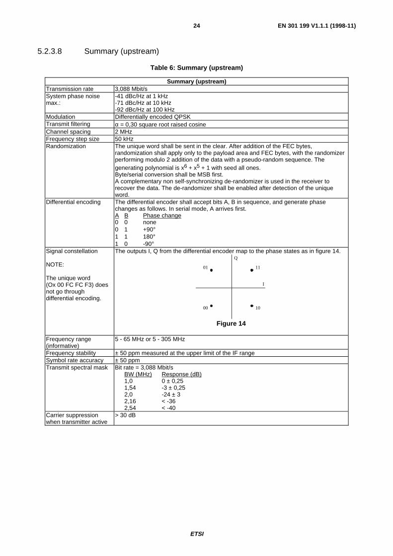
5.2.3.8 Summary (upstream)
Table 6: Summary (upstream)
Summary (upstream)Transmission rate 3,088 Mbit/sSystem phase noisemax.:
-41 dBc/Hz at 1 kHz-71 dBc/Hz at 10 kHz-92 dBc/Hz at 100 kHz
Modulation Differentially encoded QPSKTransmit filtering α = 0,30 square root raised cosineChannel spacing 2 MHzFrequency step size 50 kHzRandomization The unique word shall be sent in the clear. After addition of the FEC bytes,
randomization shall apply only to the payload area and FEC bytes, with the randomizerperforming modulo 2 addition of the data with a pseudo-random sequence. Thegenerating polynomial is x6 + x5 + 1 with seed all ones.Byte/serial conversion shall be MSB first.A complementary non self-synchronizing de-randomizer is used in the receiver torecover the data. The de-randomizer shall be enabled after detection of the uniqueword.
Differential encoding The differential encoder shall accept bits A, B in sequence, and generate phasechanges as follows. In serial mode, A arrives first.A B Phase change0 0 none0 1 +90°1 1 180°1 0 -90°
Signal constellation
NOTE:
The unique word(Ox 00 FC FC F3) doesnot go throughdifferential encoding.
The outputs I, Q from the differential encoder map to the phase states as in figure 14.
I
Q
1101
1000
Figure 14
Frequency range(informative)
5 - 65 MHz or 5 - 305 MHz
Frequency stability ± 50 ppm measured at the upper limit of the IF rangeSymbol rate accuracy ± 50 ppmTransmit spectral mask Bit rate = 3,088 Mbit/s
BW (MHz) Response (dB)1,0 0 ± 0,251,54 -3 ± 0,252,0 -24 ± 32,16 < -362,54 < -40
Carrier suppressionwhen transmitter active
> 30 dB

ETSI
EN 301 199 V1.1.1 (1998-11)25
Summary (upstream)Carrier suppressionwhen transmitter idle
The carrier suppression shall be more than 60 dB below nominal power output levelover the entire power output range (see [4] for details) and 30 dB right after or beforetransmission.Idle transmitter definition: A terminal is considered to be idle if it is 3 slots before animminent transmission or 3 slots after its most recent transmission.
I/Q amplitude imbalance < 1,0 dBI/Q phase imbalance < 2,0°Transmit power level atthe IF modulator output(upstream)
85 - 113 dBµV (RMS) (75 Ω).
5.3 Framing
5.3.1 Forward Interaction path (downstream OOB)
5.3.1.1 Signalling Link Extended Superframe (SL-ESF) framing format
The SL-ESF frame structure is shown in figure 15. The bit stream is partitioned into 4 632-bit Extended Superframes(ESF). Each ESF consists of 24 × 193-bit frames. Each frame consists of 1 Overhead (OH) bit and 24 bytes (192 bits) ofpayload.

ETSI
EN 301 199 V1.1.1 (1998-11)26
241 32 4 5 6 7 9 108 11 12 13 14 15 16 17 18 19 20 21 22 23
24 Frames
24 Frames x 193 bits = 4 632 bits
OH Payload
1 192 bits
Figure 15: SL-ESF frame structure
5.3.1.2 Frame overhead
There are 24 frame Overhead (OH) bits in the ESF which are divided into ESF Frame Alignment Signal (FAS) (F1-F6),Cyclic Redundancy Check (CRC) (C1-C6), and M-bit Data Link (DL) (M1-M12) as shown in table 7.
Table 7: Frame overhead
Frame Number Bit Number Overhead Bit Data (192 bits) 1 0 M1 2 193 C1 3 386 M2 4 579 F1 = 0 5 772 M3 6 965 C2 7 1 158 M4 8 1 351 F2 = 0 9 1 544 M5
10 1 737 C3 11 1 930 M6 12 2 123 F3 = 1 13 2 316 M7 14 2 509 C4 15 2 702 M8 16 2 895 F4 = 0 17 3 088 M9 18 3 281 C5 19 3 474 M10 20 3 667 F5 = 1 21 3 860 M11 22 4 053 C6 23 4 246 M12 24 4 439 F6 = 1
FAS: Frame Alignment Signal (F1 - F6)DL: Mbit Data Link (M1 - M12)CRC: Cyclic Redundancy Check (C1 - C6)
ETSI
EN 301 199 V1.1.1 (1998-11)27
ESF Frame Alignment Signal (FAS)
The ESF FAS is used to locate all 24 frames and overhead bit positions. The bit values of the FAS are defined asfollows:
F1 = 0, F2 = 0, F3 = 1, F4 = 0, F5 = 1, F6 = 1.
ESF Cyclic Redundancy Check (CRC)
The CRC field contains the CRC-6 check bits calculated over the previous ESF. CRC Message Block (CMB)size = 4 632 bits. Before calculation, all 24 frame Overhead (OH) bits are equal to "1". All information in the other bitpositions is unchanged. The check bit sequence C1-C6 is the remainder after multiplication by x6 and then division bythe generator polynomial x6 + x + 1 of the CMB. C1 is the MSB of the remainder. The initial remainder value is pre-setto all zeros.
ESF Mbit Data Link
The M-bits in the SL-ESF serve for slot timing assignment (see subclause 5.4).
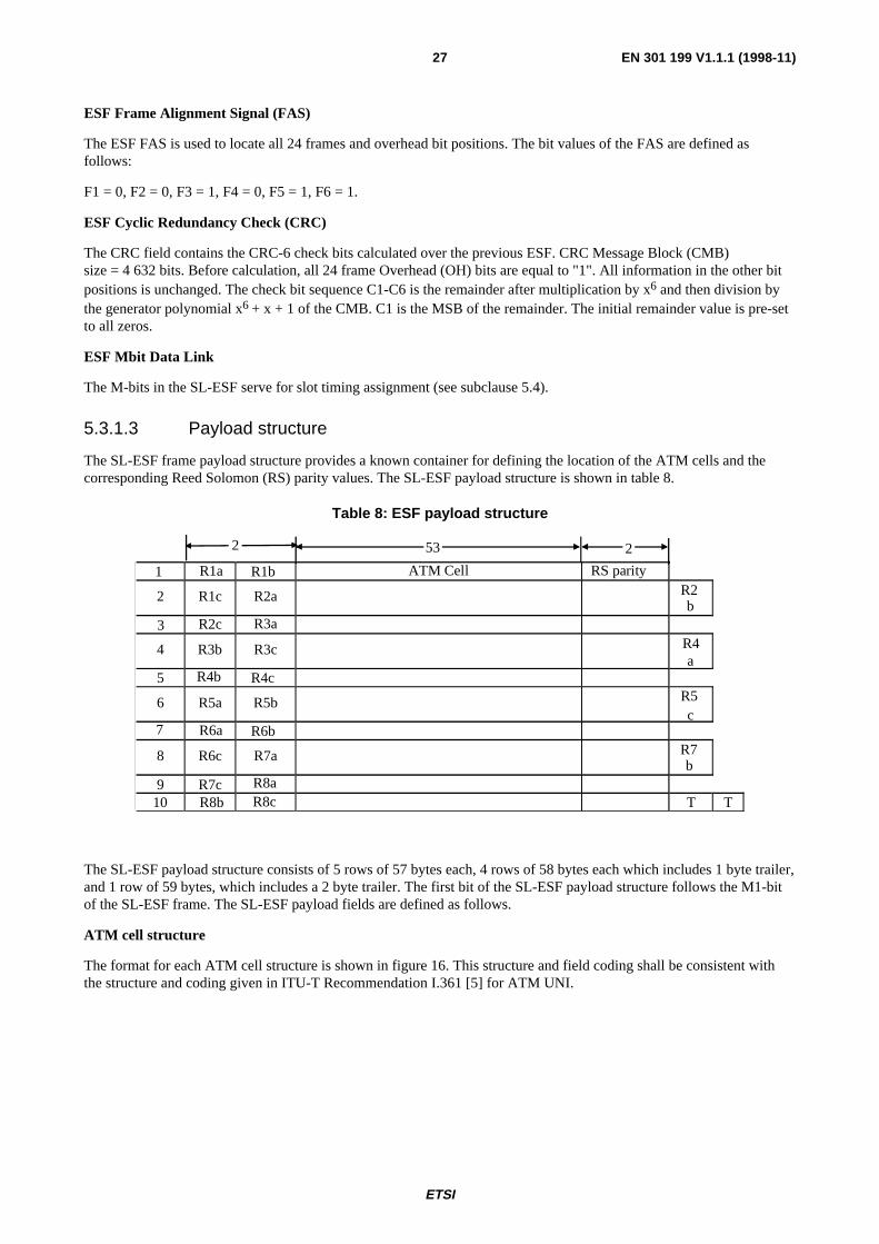
5.3.1.3 Payload structure
The SL-ESF frame payload structure provides a known container for defining the location of the ATM cells and thecorresponding Reed Solomon (RS) parity values. The SL-ESF payload structure is shown in table 8.
Table 8: ESF payload structure
1 R1a R1b ATM Cell RS parity
2 R1c R2a R2b
3 R2c R3a
4 R3b R3c R4a
5 R4b R4c
6 R5a R5b R5c
7 R6a R6b
8 R6c R7a R7b
9 R7c R8a10 R8b R8c T T
2 253
The SL-ESF payload structure consists of 5 rows of 57 bytes each, 4 rows of 58 bytes each which includes 1 byte trailer,and 1 row of 59 bytes, which includes a 2 byte trailer. The first bit of the SL-ESF payload structure follows the M1-bitof the SL-ESF frame. The SL-ESF payload fields are defined as follows.
ATM cell structure
The format for each ATM cell structure is shown in figure 16. This structure and field coding shall be consistent withthe structure and coding given in ITU-T Recommendation I.361 [5] for ATM UNI.

ETSI
EN 301 199 V1.1.1 (1998-11)28
Information PayloadHeader
384 bits40 bits
53 bytes
Figure 16: ATM cell format
Channel coding and interleaving
RS encoding with t = 1 shall be performed on each ATM cell. This means that 1 erroneous byte per ATM cell can becorrected. This process adds 2 parity bytes to the ATM cell to give a code word of (55,53).
The RS code shall have the following generator polynomials:
Code generator polynomial: g(x) = (x + µ0) (x + µ1), where µ = 02 hex
Field generator polynomial: p(x) = x8 + x4 + x3 + x2 + 1
Convolutional interleaving shall be applied to the ATM cells contained in the SL-ESF. The Rxa - Rxc bytes and the twoT bytes shall not be included in the interleaving process. Convolutional interleaving is applied by interleaving 5 lines of55 bytes.
Following the scheme in figure 17, convolutional interleaving shall be applied to the error protected packets. Theconvolutional interleaving process shall be based on the Forney approach, which is compatible with the Ramsey type IIIapproach, with I = 5. The interleaved frame shall be composed of overlapping error protected packets and a group of 10packets shall be delimited by the start of the SL-ESF.
The interleaver is composed of I branches, cyclically connected to the input byte-stream by the input switch. Eachbranch shall be a First In First Out (FIFO) shift register, with depth (M) cells (where M = N/I, N = 55 = error protectedframe length, I = interleaving depth). The input and output switches shall be synchronized.
For synchronization purposes, the first byte of each error protected packet shall be always routed into the branch "0" ofthe interleaver (corresponding to a null delay). The third byte of the SL-ESF payload (the byte immediately followingR1b) shall be aligned to the first byte of an error protected packet.
The de-interleaver is similar, in principle, to the interleaver, but the branch indexes are reversed (i.e. branch 0corresponds to the largest delay). The de-interleaver synchronization is achieved by routing the third data byte of theSL-ESF into the "0" branch.
0
M
M M
M M M
M M M M
M M M M
M M M
M M
M
0
0
2
1
3
4
0
2
1
3
4
IN OUT
CHANNEL
Figure 17: Interleaver and de-interleaver structures

ETSI
EN 301 199 V1.1.1 (1998-11)29
Reception indicator fields and slot boundary fields
Rxa-Rxc is a 24-bit field containing slot configuration information for the upstream channel "x" and is defined as:
Rxa = (b0 .....b7)
Rxb = (b8.....b15)
Rxc = (b16... b23)
= slot configuration information for the upstream channel "x" where "x" is indicated to the NIU in the"Flag set" given in MAC messages (Default Configuration Message, Connect Message, Transmission Controlmessage) corresponding to a particular upstream frequency. One channel requires two consecutive fields. "x"thus denotes first field used for a particular upstream frequency.
b0 = ranging control slot indicator for next superframe
b1-b6 = slot boundary definition field for next superframe
b7 = slot 1 reception indicator for second previous superframe
b8 = slot 2 reception indicator for second previous superframe
b9 = slot 3 reception indicator for second previous superframe
b10 = slot 4 reception indicator for second previous superframe
b11 = slot 5 reception indicator for second previous superframe
b12 = slot 6 reception indicator for second previous superframe
b13 = slot 7 reception indicator for second previous superframe
b14 = slot 8 reception indicator for second previous superframe
b15 = slot 9 reception indicator for second previous superframe
b16-17 = reservation control for next superframe
b18-b23 = CRC 6 parity
The 9 slots of this field and the 9 slots of the following field are valid.
Ranging control slot indicator (b0): when this bit is active (b0 = 1), the first three slots of upstream channel "x" whichcorrespond to the occurrence of the next superframe of the related downstream channel are designated as ranging controlslots. A ranging control message may be transmitted in the second ranging control slot, and the first and third rangingcontrol slots may not be used for transmission (guard band for ranging operations).
Slot boundary definition field (b1-b6): slot types are assigned to upstream slots using bits b0-b6. The slots aregrouped into regions within the SL-ESF such that slots of a similar type are contained within the same region. The orderof the regions is Ranging slot, Contention based slots, Reserved slots and Fixed rate based slots. If a ranging slot isavailable within a SL-ESF it will consist of the first three slot times in the SL-ESF. A ranging slot is indicated by b0 = 1.The boundaries between the remaining regions of the SL-ESF are defined by b1-b6. The boundaries are defined asshown in table 9.

ETSI
EN 301 199 V1.1.1 (1998-11)30
Table 9: Slot boundary definition field (b1-b6)
Boundary 0Boundary 1 slot 1Boundary 2 slot 2Boundary 3 slot 3Boundary 4 slot 4Boundary 5 slot 5Boundary 6 slot 6Boundary 7 slot 7Boundary 8 slot 8Boundary 9 slot 9
The boundary positions are defined by b1-b6 as shown in table 10.
Table 10: Boundary positions (b1-b6)
(note 1)(note 2)
0 1 2 3 4 5 6 7 8 9
0 (note 3) 0 1 2 3 4 5 6 7 8 9 1 (note 3) 10 11 12 13 14 15 16 17 18 2 (note 3) 19 20 21 22 23 24 25 26
3 27 28 29 30 31 32 33 4 34 35 36 37 38 39 5 40 41 42 43 44 6 45 46 47 48 7 49 50 51 8 52 53 9 54
NOTE 1: row = Contention based / Reserved region boundary.NOTE 2: column = Reserved packet /Fixed rate based region boundary.NOTE 3: When the ranging control slot indicator (b0) is set to "1", the
values in rows 0 - 2 are illegal values, and values in row 3 meansthat there are no aloha slots, because slots 1 - 3 are defined asranging control slots.
Example: b0 = 0, b1-b6 = 22: contention (1-2), reserved (3-5), fixed rate (6-9)
The remaining values of the slot boundary definition field are provided in table 11.
Table 11: Slot boundary definition field
b1-b6value
ranging controlslots
contention slots reservationslots
fixed rateslots
55 1-6 7-9 - -56 1-6 7-8 - 957 1-6 7 8-9 -58 1-6 7 8 959 1-6 7 - 8-960 1-6 - 7-8 961 1-6 - 7 8-962 1-6 - - 7-963 1-9 - - -

ETSI
EN 301 199 V1.1.1 (1998-11)31
For b1-b6 = 55 - 63, b0 shall be set to 1.
For b1-b6 between 55 and 62, two ranging slots are provided (2 and 5).
For b1-b6 = 63, three ranging slots are provided (2, 5, and 8).
The values in tables 11 to 13 are derived from b1-b6 in the following manner:
b1 + (b2 × 2) + (b3 × 4) + (b4 × 8) + (b5 × 16) + (b6 × 32)
Slot reception indicators (b7-b15): When a slot reception indicator is active ("1"), this indicates that a cell wasreceived without collision. The relationship between a given US slot and its indicator is shown in table 12. When theindicator is inactive ("0"), this indicates that either a collision was detected or no cell was received in the correspondingupstream slot.
Table 12: Relationship of US slot to DS indicator
1,544M downstream 3,088M downstream256k non applicable non applicable
1,544M non applicable non applicable3,088M non applicable
DS
US
I
9 slots
1 Frame
I indicates the DS slot in which Indicators are sent.These indicators are for the US slots in the shadedarea.
Reservation control (b16-b17): when the reservation control field has the value of 0, no reservation attempts areallowed to be transmitted on the corresponding QPSK upstream channel during the slot positions associated with thenext 3 ms period. When the reservation control field has the value of 1, reservation attempts can be made. The values 2and 3 are reserved.
CRC 6 parity (b18-b23): this field contain a CRC 6 parity value calculated over the previous 18 bits. The CRC 6 parityvalue is described in the SL-ESF frame format.
In the case where there is more than one OOB DS QPSK channel related to an upstream QPSK channel, the SL-ESFoverhead bits and the payload R-bytes shall be identical in those OOB DS channels, with the exception of the overheadCRC (C1-C6) bits, which are specific to each of those OOB DS channels. Such related DS channels shall besynchronized.
The MAC messages that are required to perform the MAC functions for the upstream channel shall be transmitted oneach of its related OOB DS channels.
Trailer bytes
These bytes are not used. They are equal to 0.

ETSI
EN 301 199 V1.1.1 (1998-11)32
5.3.2 Forward interaction path (downstream IB)
The structure that is utilized when the downstream QPSK channel is carrying MPEG2-TS packets is shown in figure 18.
4 3 2 3 26 26 40 40 40 4MPEGHeader
UpstrmMarker
SlotNumber
MAC FlgControl
MACFlags
Ext.Flags
MACmsg.
MAC msg. MAC msg. rsrvc
Figure 18: Frame structure (MPEG2-TS format)
where:
MPEG header is the 4 byte MPEG2-TS header as defined in ISO 13818-1 [2] with a specific PID designated for MACmessages.
upstream marker is a 24-bit field which provides upstream QPSK synchronization information. The definitionof the field is as follows:
bit 0: upstream marker enable (MSB)
When this field has the value "1", the slot marker pointer is valid. When this field has the value "0",the slot marker pointer is not valid.
bit 1 - 7: reserved
bit 8 - 23: upstream slot marker pointer
The slot marker pointer is a 16-bit integer which indicates the number of "symbol" clocks between thefirst symbol of the next sync byte and the next 3 ms marker.
slot number is a 16-bit field which is defined as follows:
bit 0: slot position register enable (MSB)
When this field has the value "1", the slot position register is valid. When this field has the value "0",the slot position register is not valid.
bit 1 - 3: reserved
bit 4 is set to the value "1". This bit is equivalent to M12 in the case of OOB downstream.
bit 5: odd parity
This bit provides odd parity for upstream slot position register. This bit is equivalent to M11 in thecase of OOB downstream.
bits 6 - 15: upstream slot position register
The upstream slot position register is a 10-bit counter which counts from 0 to n with bit 6 the MSB.These bits are equivalent to M10-M1 in the case of OOB downstream.
(see subclause 5.4 for more information on the functionality of the upstream slot position register)
ETSI
EN 301 199 V1.1.1 (1998-11)33
MAC Flag Control is a 24-bit field (b0, b1, b2...b23) which provides control information which is used inconjunction with the MAC flags and extension flags. The definition of the MAC flag control field is as follows:
b0-b2 channel 1 flag field control
b3-b5 channel 2 flag field control
b6-b8 channel 3 flag field control
b9-b11 channel 4 flag field control
b12-b14 channel 5 flag field control
b15-b17 channel 6 flag field control
b18-b20 channel 7 flag field control
b21-b23 channel 8 flag field control
Each of the above channel "x" flag field control fields are defined as follows:
channel x flag control (a, b, c)
bit a: 0 - channel x flag field disabled
1 - channel x flag field enabled
bit b, c: 00 - all flags valid for second previous 3 ms period
(out-of-band signalling equivalent)
01 - flags valid for 1st ms of previous 3 ms period
10 - flags valid for 2nd ms of previous 3 ms period
11 - flags valid for 3rd ms of previous 3 ms period
MAC Flags
MAC Flags is a 26-byte field containing 8 slot configuration fields (24 bits each) which contain slotconfiguration information for the related upstream channels followed by two reserved bytes. Thedefinition of each slot configuration field is defined as follows:
b0 = ranging control slot indicator for next 3 ms period (MSB)
b1-b6 = slot boundary definition field for next 3 ms period
b7 = slot 1 reception indicator for [second] previous 3 ms period
b8 = slot 2 reception indicator for [second] previous 3 ms period
b9 = slot 3 reception indicator for [second] previous 3 ms period
b10 = slot 4 reception indicator for [second] previous 3 ms period
b11 = slot 5 reception indicator for [second] previous 3 ms period
b12 = slot 6 reception indicator for [second] previous 3 ms period
b13 = slot 7 reception indicator for [second] previous 3 ms period
b14 = slot 8 reception indicator for [second] previous 3 ms period
b15 = slot 9 reception indicator for [second] previous 3 ms period
b16-17 = reservation control for next 3 ms period
b18-b23= CRC 6 parity
ETSI
EN 301 199 V1.1.1 (1998-11)34
The slot configuration fields are used in conjunction with the MAC flag control field defined above. When theMAC flag control field designates that a 1 ms flag update is enabled; (1) the reception indicators refer to theprevious 3 ms period (the bracketed term [second] is omitted from the definition), (2) only the receptionindicators which relate to slots which occur during the designated 1 ms period are valid, and (3) the rangingcontrol slot indicator, slot boundary definition field, and reservation control field are valid and consistentduring each 3 ms period.
MAC Message
The MAC Message field contains a 40-byte message, the general format defined in the subclause 5.5.
reserve field c is a 4-byte field reserved for future use.
5.3.3 Return interaction path (upstream)
5.3.3.1 Slot format
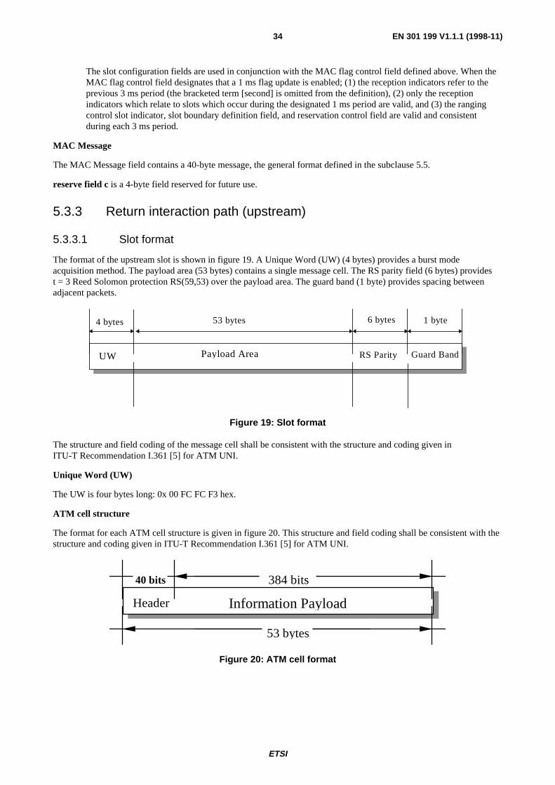
The format of the upstream slot is shown in figure 19. A Unique Word (UW) (4 bytes) provides a burst modeacquisition method. The payload area (53 bytes) contains a single message cell. The RS parity field (6 bytes) providest = 3 Reed Solomon protection RS(59,53) over the payload area. The guard band (1 byte) provides spacing betweenadjacent packets.
Payload Area Guard Band
53 bytes 1 byte
UW
4 bytes
RS Parity
6 bytes
Figure 19: Slot format
The structure and field coding of the message cell shall be consistent with the structure and coding given inITU-T Recommendation I.361 [5] for ATM UNI.
Unique Word (UW)
The UW is four bytes long: 0x 00 FC FC F3 hex.
ATM cell structure
The format for each ATM cell structure is given in figure 20. This structure and field coding shall be consistent with thestructure and coding given in ITU-T Recommendation I.361 [5] for ATM UNI.
Information PayloadHeader
384 bits40 bits
53 bytes
Figure 20: ATM cell format

ETSI
EN 301 199 V1.1.1 (1998-11)35
Channel coding
RS encoding shall be performed on each ATM cell with T = 3. This means that 3 erroneous byte per ATM cell can becorrected. This process adds 6 parity bytes to the ATM cell to give a code word of (59,53).
The RS code shall have the following generator polynomials:
Code generator polynomial:
g(x) = (x + µ0) (x + µ1) (x + µ2) ... (x + µ5),
where µ = 02 hex
Field generator polynomial:
p(x) = x8 + x4 + x3 + x2 + 1
Guard band
The guard band is 1-byte long (4 QPSK symbols). It provides some extra protection against synchronization errors.
5.4 Slot timing assignment
5.4.1 Downstream slot position reference (downstream OOB)
Upstream synchronization is derived from the downstream extended superframe (OOB) by noting the slot positions asshown in table 13.
Table 13: Downstream slot position reference
FrameNumber
BitNumber
OverheadBit
Slot positionreference
1 0 M1 ♦ Slot Position (note) 2 193 C1 3 386 M2 4 579 F1 = 0 5 772 M3 6 965 C2 7 1 158 M4 8 1 351 F2 = 0 9 1 544 M5 ♦ Slot Position
10 1 737 C3 11 1 930 M6 12 2 123 F3 = 1 13 2 316 M7 14 2 509 C4 15 2 702 M8 16 2 895 F4 = 0 17 3 088 M9 ♦ Slot Position 18 3 281 C5 19 3 474 M10 20 3 667 F5 = 1 21 3 860 M11 22 4 053 C6 23 4 246 M12 24 4 439 F6 = 1
NOTE: For the 3,088 Mbit/s rate downstream, the 3 ms time marker onlyappears once every two superframes. The M12 bit (see subclause 5.4)is used to differentiate between the two superframes.

ETSI
EN 301 199 V1.1.1 (1998-11)36
5.4.2 Downstream slot position reference (downstream IB)
Upstream synchronization is derived from the downstream extended superframe (IB) by noting the 3 ms time markerdownstream as shown in figure 21. From the bits of the upstream marker field contained in the MPEG2-TS packet, the3 ms time marker is obtained by counting a number of symbol clocks equal to (b23-b8). This marker is equivalent to thefirst slot position of the superframe for the OOB case.
Figure 21: Position of the 3 ms time marker for IB signalling
In order to describe how the upstream marker is derived from the location of the 3 ms marker, consider the followingsystem diagram.
D IB
d3D L + dL
D 2
D IA
D S D 1
H e a d e n d D e l a y s Da ta L inkDe lays
Se t top Box De lays
d v a d v b
Figure 22: System model for timing analysis
The delay between the location of the end of the upstream marker and the beginning of the next sync byte, designated asDS, is a constant value for each bit rate equal to the equivalent time of 194 bytes, or (194 × 8/2) symbol clocks.
There will be some processing delay in the head-end hardware between the location where the upstream marker isinserted in the MAC packet and the arrival of the data into the interleaver. This should be a constant delay, D1, which is
the same for every incoming byte, including the sync byte following the upstream marker.
The delay due to the interleaving process in the head-end is DIA and will be zero for each sync byte.
There is an additional delay, dva, due to the convolutional coding process if any; this delay will be code rate dependant,according to the DVB-MS specification (It is also design dependant).
There will be some processing delay in the head-end hardware between the output of the inner coder and the output ofthe QPSK modulator. This should be a constant delay, D2, for every byte in the outgoing stream.
The data link is composed of two delay values, DL, the constant link delay that every STU experiences, and dL, the
variable link delay for each STU which is due to the fact that each STU is located at a different distance from thehead-end.This variable link delay is compensated for by the ranging operation.

ETSI
EN 301 199 V1.1.1 (1998-11)37
There will be some processing delay in the STU hardware between the input of the QPSK demodulator and the input ofthe convolutional decoder. This delay is design dependent, d3, and may be a constant delay or a variable delay for each
byte in the data stream.
There is an additional delay, dvb, which is due to the convolutional decoder; this delay is code rate dependant,according to the DVB-MS specification. It is also design dependant.
The delay due to the de-interleaving process in the STU is DIB, and will be equal to the entire interleave delay for each
sync byte.
The total interleave delay, DI = DIA + DIB
will be constant for each byte. The value will be given by:
DI = 204 × 8 × interleave_depth / bit rate.
There will be some processing delay in the STU hardware between the output of the de-interleaver and the circuitry thatutilizes the upstream marker and following sync byte for generating the local 3 ms marker. This delay, which includesRS FEC, is design dependent, d4, and may be a constant delay or a variable delay for each byte in the data stream.
The accumulated delay in the data link is composed of a number of constant terms and variable terms. The constantterms will be identical for every STU that is utilizing a particular QPSK channel for in-band timing and thus becomes afixed offset between when the counter which is loading the upstream marker value and the actual location of the 3 msmarker at each STU. Each STU is responsible for compensating for the design dependent delays, before utilizing theupstream marker value for generating the 3 ms marker. The variable link delay, dL, will be compensated for via the
ranging algorithm, in the same way as performed when out-of-band signalling is employed.
5.4.3 Upstream slot positions
Transmission on each QPSK upstream channel is based on dividing access by multiple NIU units by utilizing anegotiated bandwidth allocation slot access method. A slotting methodology allows the transmit slot locations to besynchronies to a common slot position reference, which is provided via the related downstream MAC control channel.Synchronizing the slot locations increases message throughput of the upstream channels since the ATM cells do notoverlap during transmission.
The slot position reference for upstream slot locations is received via the related downstream MAC control channel byeach NIU. Since each NIU receives the downstream slot position reference at a slightly different time, due topropagation delay in the transmission network, slot position ranging is required to align the actual slot locations for eachrelated upstream channel. The upstream slot rates are 6 000 upstream slots/s.
The number of slots available in any one second is given by:
number of slots/s = upstream data rate / 512 + (extra guard band)
where extra guard band may be designated between groups of slots for alignment purposes. The M-bits in the SL-ESFserve two purposes:
- to mark the slot positions for the upstream contention based and contention-less based signalling links(see subclause 5.4.4);
- to provide slot count information for upstream message bandwidth allocation management in the NIU.
M-bits M1, M5, and M9 mark the start of an upstream slot position for upstream message transmission.
3 ms period
k k +
1
k +
2
k +
3
k +
4
k +
5
k +
6
k +
7
k +
8
k +
9
k +
10
k +
11
k +
12
k +
13
k +
14
k +
15
k +
16
k +
17
k +
18
k +
19

ETSI
EN 301 199 V1.1.1 (1998-11)38
As the downstream and upstream bit rates are 3,088 Mbit/s, there are 6 slot position references downstream during thetransmission of 18 upstream packets. In the case of IB downstream, packet "k" is sent when the 3 ms time marker isreceived.
The relationship between the received slot position reference and the actual slot transmit position is given by:
slot_transmit_position = slot_position_reference + slot_position_offset
where slot_position_offset is derived from the Time_Offset_Value provided via theRange_and_Power_Calibration_Message.
← slot_transmit_position
slot (j-1) slot (j)
Å slot_position_offset Æ
slot position reference (downstream)
The actual slot transmission locations are given by
slot_transmission_location (m) = slot_transmission_position + (m × 512);
where m = 0,1,2,3,4,5; is the position of the slot with respect to the slot_transmission_position
←slot_transmission_position ←slot_transmission_position
Å pos0
Å
pos 1
Å pos2
Å
pos 3
Å pos4
Å
pos 5
previous slot slot 0(m=0)
slot1(m=1)
slot 2(m=2)
slot 3(m=3)
slot 4(m=4)
slot 4(m=5)
next slot
512bits
512bits
512bits
512bits
512bits
512bits
16 bits
5.4.4 Slot position counter
Think of M-bits M10 - M1 as a register, called the upstream slot position register, which is used to generate an upstreamslot position counter, which counts from 0 to n, where n is an integer which indicates slot position cycle size (the valueof n is sent in the MAC default configuration message as Service_Channel_Last_Slot). The upstream slot positionregister indicates the upstream slot positions that will correspond to the next SL-ESF frame. Upstream slot positions arecounted from 0 to n. There are 6 upstream slots per millisecond. The corresponding upstream slot rates are, therefore,6 000 upstream slots/s when the upstream data rate is 3,088 Mbit/s. The algorithm to determine the upstream slotposition counter value is given below:

ETSI
EN 301 199 V1.1.1 (1998-11)39
n = 1;
upstream_slot_position_register = value of M-bits latched at bit_position M11 (M10 - M1)
m = 6;
if (bit_position==M1 and previous M12 ==1)
upstream_slot_position_counter = upstream_slot_register * 3 * m;
if (bit_position == M5)
if (previous M12 == 0) )
upstream_slot_position_counter =
upstream_slot_position_counter+m;
if (bit_position == M9)
if (previous M12 == 1) )
upstream_slot_position_counter = upstream_slot_position_counter + m;
if (bit_position == M11)
temp_upstream_slot_position_register = (M10, M9, M8, ...., M1);
if ( (bit_position == M12 and M12 == 1) )
upstream_slot_position = temp_upstream_slot_position_register;
where, the M-bits will be defined as follows:
M1 - M10 = 10-bit ESF counter which counts from 0 to n with M10 the MSB;
M11 = odd parity for the ESF counter, i.e., M11 = 1 if the ESF_value (M1-M10) has an evennumber of bits set to 1;
M12 = 1: ESF counter valid;
0: ESF counter not valid.
The values assigned to M12 are as follows:
The information is always transmitted in pairs of superframe, where superframe A is the first superframe in thepair, and superframe B is the second superframe in the pair. The M12 bit of superframe A is set to the value "0"and the M12 bit of superframe B is set to the value "1".
When the downstream channel is IB, M12 = 1.
5.5 MAC functionality
5.5.1 MAC reference model
This subclause is limited to the definition and specification of the MAC layer protocol. The detailed operations withinthe MAC layer are hidden from the above layers.
This subclause focuses on the required message flows between the INA and the NIU for MAC. These areas are dividedinto three categories:
1) initialization, provisioning and sign-on management;
2) connection management; and
3) link management.

ETSI
EN 301 199 V1.1.1 (1998-11)40
Higher Layers
Physical
Multicast Address Resolution
Singlecast Address Resolution
DataAdaptation MAC
Sublayer
MAC Signaling
ConnectionManagement
MAC Management Entit y
Initialization,Sign-On andProvisioningManagement
LinkManagement
Physical
MAC
LLC
IEEE 802 Reference Model
LowerLayerProtocols
Figure 23: MAC reference model
5.5.2 MAC concept
5.5.2.1 Relationship between higher layers and MAC protocol
The goal of the MAC protocol is to provide tools for higher layer protocols in order to transmit and receive datatransparently and independently of the physical layer. Higher layer services are provided by the INA to the STU. TheINA is thus responsible of indicating the transmission mode and rate to the MAC layer for each type of service.
Specifically, for each connection provided by higher layers on the INA side (VPI/VCI), a connection ID is associated atthe MAC layer. The maximum number of simultaneous connections that a NIU should support is defined as follows:
Grade A: Only one connection at a time can be handled by a NIU.
Grade B: As many connections as needed, defined dynamically by the INA, following higher layers requests.
However, bandwidth (time slots) does not need to be assigned immediately by the INA for a given connection. Thismeans that a connection ID may exist at the NIU side without associated slot numbers.
The INA is responsible of providing transmission bandwidth to the NIUs when needed by higher layers. However, sincethe NIU shall transmit all data from the STU, the NIU is also responsible for requesting for more bandwidth if notalready provided by the INA.
A default connection is initiated by the INA when STBs are first turned on. This connection can be used to send datafrom higher layers leading to further interactive connections. This connection can be associated to a zero transmissionrate (no initial bandwidth allocation).

ETSI
EN 301 199 V1.1.1 (1998-11)41
5.5.2.2 Relationship between physical layer and MAC protocol
Up to 8 QPSK Upstream channels can be related to each downstream channel which is designated as a MAC controlchannel. An example of frequency allocation is shown in the figure 24. This relationship consists of the following items:
1) Each of these related upstream channels share a common slot position. This reference is based on 1 ms timemarkers that are derived via information transmitted via the downstream MAC control channel.
2) Each of these related upstream channels derive slot numbers from information provided in the downstream MACcontrol channel.
3) The messaging needed to perform MAC functions for each of these related upstream channels is transmitted viathe downstream MAC control channel.
The MAC protocol supports multiple downstream channels. In instances where multiple channels are used, the INAshall specify a single OOB frequency called the Provisioning Channel, where NIUs perform Initialization andProvisioning Functions. In networks where IB NIUs exist, provisioning should be included in at least one IB channel.An aperiodic message is sent on each downstream control channel which points to the downstream ProvisioningChannel. In instances where only a single frequency is in use, the INA shall utilize that frequency for Initialization andProvisioning functions.
The MAC protocol supports multiple upstream channels. One of the upstream channels shall be designated the ServiceChannel. The Service Channel shall be used by NIUs entering the network via the Initialization and Provisioningprocedure. The remaining upstream channels shall be used for upstream data transmission. In cases where only oneupstream channel is utilized, the functions of the Service Channel shall reside in conjunction with regular upstream datatransmission.
Figure 24: Example of frequency allocation
5.5.2.3 Relationship between physical layer slot position counter and MAC slotassignment
M10 - M1 is a 10-bit superframe counter at the INA side, whereas the upstream slot position counter is an upstream slotcounter at the NIUs side. The NIU slot position counter (M10-M1 × 3 × m, where m = 6) may be implemented as a16-bit counter which is compared to the 16-bit slot numbers assigned by the INA in MAC messages (list assignment).When the counter value equals any assigned value, the NIU is allowed to send a packet upstream.
In the algorithm given in subclause 5.4.3, the counter value is refreshed every time M11 is received.
5.5.2.4 Access modes (contention/ranging/fixed rate/reservation)
Different access modes are provided to the NIUs within access regions specified by information contained in the slotboundary fields of the downstream superframes. The limits between access regions allow users to know when to senddata on contention without risks of collision with contentionless type data. The following rules define how to selectaccess modes:
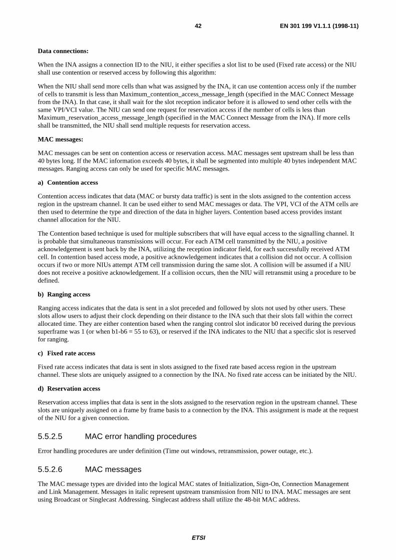
ETSI
EN 301 199 V1.1.1 (1998-11)42
Data connections:
When the INA assigns a connection ID to the NIU, it either specifies a slot list to be used (Fixed rate access) or the NIUshall use contention or reserved access by following this algorithm:
When the NIU shall send more cells than what was assigned by the INA, it can use contention access only if the numberof cells to transmit is less than Maximum_contention_access_message_length (specified in the MAC Connect Messagefrom the INA). In that case, it shall wait for the slot reception indicator before it is allowed to send other cells with thesame VPI/VCI value. The NIU can send one request for reservation access if the number of cells is less thanMaximum_reservation_access_message_length (specified in the MAC Connect Message from the INA). If more cellsshall be transmitted, the NIU shall send multiple requests for reservation access.
MAC messages:
MAC messages can be sent on contention access or reservation access. MAC messages sent upstream shall be less than40 bytes long. If the MAC information exceeds 40 bytes, it shall be segmented into multiple 40 bytes independent MACmessages. Ranging access can only be used for specific MAC messages.
a) Contention access
Contention access indicates that data (MAC or bursty data traffic) is sent in the slots assigned to the contention accessregion in the upstream channel. It can be used either to send MAC messages or data. The VPI, VCI of the ATM cells arethen used to determine the type and direction of the data in higher layers. Contention based access provides instantchannel allocation for the NIU.
The Contention based technique is used for multiple subscribers that will have equal access to the signalling channel. Itis probable that simultaneous transmissions will occur. For each ATM cell transmitted by the NIU, a positiveacknowledgement is sent back by the INA, utilizing the reception indicator field, for each successfully received ATMcell. In contention based access mode, a positive acknowledgement indicates that a collision did not occur. A collisionoccurs if two or more NIUs attempt ATM cell transmission during the same slot. A collision will be assumed if a NIUdoes not receive a positive acknowledgement. If a collision occurs, then the NIU will retransmit using a procedure to bedefined.
b) Ranging access
Ranging access indicates that the data is sent in a slot preceded and followed by slots not used by other users. Theseslots allow users to adjust their clock depending on their distance to the INA such that their slots fall within the correctallocated time. They are either contention based when the ranging control slot indicator b0 received during the previoussuperframe was 1 (or when b1-b6 = 55 to 63), or reserved if the INA indicates to the NIU that a specific slot is reservedfor ranging.
c) Fixed rate access
Fixed rate access indicates that data is sent in slots assigned to the fixed rate based access region in the upstreamchannel. These slots are uniquely assigned to a connection by the INA. No fixed rate access can be initiated by the NIU.
d) Reservation access
Reservation access implies that data is sent in the slots assigned to the reservation region in the upstream channel. Theseslots are uniquely assigned on a frame by frame basis to a connection by the INA. This assignment is made at the requestof the NIU for a given connection.
5.5.2.5 MAC error handling procedures
Error handling procedures are under definition (Time out windows, retransmission, power outage, etc.).
5.5.2.6 MAC messages
The MAC message types are divided into the logical MAC states of Initialization, Sign-On, Connection Managementand Link Management. Messages in italic represent upstream transmission from NIU to INA. MAC messages are sentusing Broadcast or Singlecast Addressing. Singlecast address shall utilize the 48-bit MAC address.

ETSI
EN 301 199 V1.1.1 (1998-11)43
Table 14: MAC messages
Message Type Value
Addressing Type
0x010x020x030x040x050x060x07
0x08-0x1F
MAC Initialization, Provisioning and Sign-On Message Provisioning Channel Message Default Configuration Message Sign-On Request Message Sign-On Response Message Ranging and Power Calibration Message Ranging and Power Calibration Response Message Initialization Complete Message [Reserved]
BroadcastBroadcastBroadcastSinglecastSinglecastSinglecastSinglecast
0x20-0x3F0x200x210x220x230x240x250x260x270x280x290x2A0x2B
0x2C-0x3F
MAC Connection Establishment and Termination Msgs Connect Message Connect Response Message Reservation Request Message Reservation Response Message Connect Confirm Message Release Message Release Response Message Idle Message Reservation Grant Message Reservation ID Assignment Reservation Status Request Reservation ID Response Message Reserved]
SinglecastSinglecastSinglecastBroadcastSinglecastSinglecastSinglecastSinglecastBroadcastSinglecastSinglecastSinglecast
0x270x400x410x420x430x44
0x45-0x5F
MAC Link Management Messages Idle Message Transmission Control Message Reprovision Message Link Management Response Message Status Request Message Status Response Message [Reserved]
SinglecastSinglecast or Broadcast
SinglecastSinglecastSinglecastSinglecast
To support the delivery of MAC related information to and from the NIU, a dedicated Virtual Channel shall be utilized.The VPI, VCI for this channel shall be 0x000,0x0021.
Upstream MAC messages:
AAL5 (as specified in ITU-T Recommendation I.363 [6]) adaptation shall be used to encapsulate each MAC PDU in anATM cell. Upstream MAC information should be single 40 bytes cell messages.
Downstream OOB MAC messages:
AAL5 (as specified in ITU-T Recommendation I.363 [6]) adaptation shall be used to encapsulate each MAC PDU in anATM cell. Downstream OOB MAC information may be longer than 40 bytes.
Downstream IB MAC messages:
Downstream IB MAC information is limited to 120-byte long messages (A procedure to be able to send longer messagesis under definition). No AAL5 layer is defined for MPEG2-TS cells. MAC messages shall therefore be sent as explainedin figure 25.

ETSI
EN 301 199 V1.1.1 (1998-11)44
Are the f i rs t two by tes o f MACmessage equa l to ze ro?
Y E S
N O
Check f i r s t MAC message f i e ld
Is the length of message in f i rs tf ie ld greater than 40 bytes ?
N O
Check second MAC message f i e l d
Are the f i rs t two by tes o f MACmessage equa l to ze ro?
S i n g l e M A Cmessagede tec ted
Y E S Is the length
o f the messagegreater than80 by tes ?
N o M A Cmessagesde tec ted
N O
Y E S
N O
Is the length o f message in secondf ie ld greater than 40 bytes ?
N O
T w o M A Cmessagesde tec ted
Y E S
Check th i rd MAC message f i e ld Check th i rd MAC message f i e ld
Are the f i rs t two bytes of theMAC message equa l t o ze ro?
Are the f i rs t two bytes o f theMAC message equa l t o ze ro?
T w o M A Cmessagesde tec ted
Y E S
O n e M A Cmessagede tec ted
N ON O
T h r e e M A Cmessagesde tec ted
Y E S
Y E S
Figure 25: Algorithm when MAC message are sent IB downstream
Since MAC related information is terminated at the NIU and INA a privately defined message structure will be utilized.The format of this message structure is illustrated in table 15. All messages are sent most significant bit first. Message0x23 is not used in the present release of the MAC protocol. When no MAC_Address is specified in the message, itmeans that the message is sent broadcast. (Syntax_indicator = 000).

ETSI
EN 301 199 V1.1.1 (1998-11)45
Table 15: MAC message structure
MAC_message() Bits Bytes Bit NumberDescription
Message_Configuration 8 1 Protocol_Version 5 Syntax_Indicator 3
Message_Type 8 1 if (syntax_indicator== 001) MAC_Address (48) (6) MAC_Information_Elements () N
Protocol Version
Protocol_Version is a 5-bit field used to identify the current MAC version. The value for this parameter is given intable 16.
Table 16: Protocol_version coding
Value Definition0-31 Reserved
Syntax Indicator
Syntax_Indicator is a 3-bit enumerated type that indicates the addressing type contained in the MAC message.
Table 17
Enum Syntax_Indicator No_MAC_Address, MAC_Address_Included, reserved2..7;
MAC Address
MAC_Address is a 48-bit value representing the unique MAC address of the NIU. This MAC address may be hardcoded in the NIU or be provided by external source.
5.5.3 MAC initialization and provisioning
This subclause defines the procedure for initialization and provisioning that the MAC shall perform during power on orreset.
1) Upon a NIU becoming active (i.e. powered up), it shall first find the current provisioning frequency. The NIUshall receive the <MAC> Provisioning Channel Message. This message shall be sent aperiodically on alldownstream OOB channels when there are multiple channels. In the case of only a single channel, the messageshall indicate the current channel is to be utilized for Provisioning. Upon receiving this message, the NIU shalltune to the Provisioning Channel.
2) After a valid lock indication on a Provisioning Channel, the NIU shall await the <MAC> DEFAULTCONFIGURATION MESSAGE . When received, the NIU shall configure its parameters as defined in thedefault configuration message. The Default Configuration Parameters shall include default timer values, defaultpower levels, default retry counts as well as other information related to the operation of the MAC protocol.

ETSI
EN 301 199 V1.1.1 (1998-11)46
Figure 26 shows the signalling sequence.
<MAC> DefaultConfiguration Message
NIU/STBINA
<MAC> ProvisioningChannel Message
Figure 26: Initialization and provisioning signalling
5.5.3.1 <MAC> Provisioning channel message (Broadcast downstream)
The <MAC> PROVISIONING CHANNEL MESSAGE is sent by the INA to direct the NIU to the proper OOBfrequency where provisioning is performed. The format of the message is shown in table 18.
Table 18: Provisioning channel message format
Provisioning_Channel_Message() Bits Bytes Bit Number /Description
Provisioning_Channel_Control_Field 8 1reserved 7 7-1:provisioning_frequency_included 1 0: no=0, yes=1
if (provisioning_frequency_included) Provisioning_Frequency (32) (4)
DownStream_Type 8 1
Provisioning Channel Control Field
Provisioning_Channel_Control_Field is used to specify the downstream frequency where the NIU will be provisioned.
Provisioning frequency included
Provisioning_frequency_included is a boolean when set, indicates that a downstream OOB IF frequency is specified thatthe NIU should tune to begin the provisioning process. When cleared, indicates that the current downstream IFfrequency is the provisioning frequency.
Provisioning frequency
Provisioning_frequency is a 32-bit unsigned integer representing the OOB IF frequency in which NIU provisioningoccurs. The unit of measure is Hz.
Downstream Type
DownStream_Type is an 8-bit enumerated type indicating the modulation format for the down stream connection.reserved, reserved, QPSK_3,088, 3..255 reserved
5.5.3.2 <MAC> Default configuration message (Broadcast downstream)
The <MAC> DEFAULT CONFIGURATION MESSAGE is sent by the INA to the NIU. The message provides defaultparameter and configuration information to the NIU. The format of the message is shown in table 19.
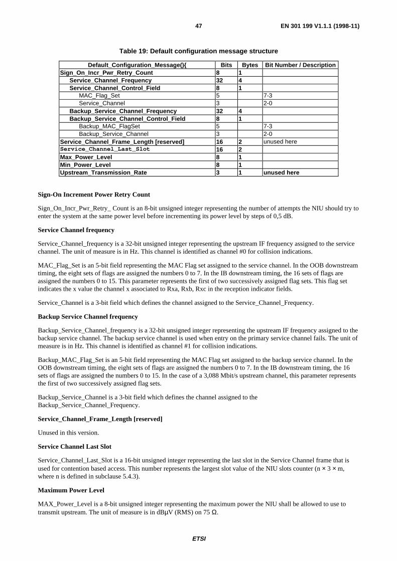
ETSI
EN 301 199 V1.1.1 (1998-11)47
Table 19: Default configuration message structure
Default_Configuration_Message() Bits Bytes Bit Number / DescriptionSign_On_Incr_Pwr_Retry_Count 8 1
Service_Channel_Frequency 32 4Service_Channel_Control_Field 8 1
MAC_Flag_Set 5 7-3Service_Channel 3 2-0
Backup_Service_Channel_Frequency 32 4Backup_Service_Channel_Control_Field 8 1
Backup_MAC_FlagSet 5 7-3Backup_Service_Channel 3 2-0
Service_Channel_Frame_Length [reserved] 16 2 unused hereService_Channel_Last_Slot 16 2Max_Power_Level 8 1Min_Power_Level 8 1Upstream_Transmission_Rate 3 1 unused here
Sign-On Increment Power Retry Count
Sign_On_Incr_Pwr_Retry_ Count is an 8-bit unsigned integer representing the number of attempts the NIU should try toenter the system at the same power level before incrementing its power level by steps of 0,5 dB.
Service Channel frequency
Service_Channel_frequency is a 32-bit unsigned integer representing the upstream IF frequency assigned to the servicechannel. The unit of measure is in Hz. This channel is identified as channel #0 for collision indications.
MAC_Flag_Set is an 5-bit field representing the MAC Flag set assigned to the service channel. In the OOB downstreamtiming, the eight sets of flags are assigned the numbers 0 to 7. In the IB downstream timing, the 16 sets of flags areassigned the numbers 0 to 15. This parameter represents the first of two successively assigned flag sets. This flag setindicates the x value the channel x associated to Rxa, Rxb, Rxc in the reception indicator fields.
Service_Channel is a 3-bit field which defines the channel assigned to the Service_Channel_Frequency.
Backup Service Channel frequency
Backup_Service_Channel_frequency is a 32-bit unsigned integer representing the upstream IF frequency assigned to thebackup service channel. The backup service channel is used when entry on the primary service channel fails. The unit ofmeasure is in Hz. This channel is identified as channel #1 for collision indications.
Backup_MAC_Flag_Set is an 5-bit field representing the MAC Flag set assigned to the backup service channel. In theOOB downstream timing, the eight sets of flags are assigned the numbers 0 to 7. In the IB downstream timing, the 16sets of flags are assigned the numbers 0 to 15. In the case of a 3,088 Mbit/s upstream channel, this parameter representsthe first of two successively assigned flag sets.
Backup_Service_Channel is a 3-bit field which defines the channel assigned to theBackup_Service_Channel_Frequency.
Service_Channel_Frame_Length [reserved]
Unused in this version.
Service Channel Last Slot
Service_Channel_Last_Slot is a 16-bit unsigned integer representing the last slot in the Service Channel frame that isused for contention based access. This number represents the largest slot value of the NIU slots counter (n × 3 × m,where n is defined in subclause 5.4.3).
Maximum Power Level
MAX_Power_Level is a 8-bit unsigned integer representing the maximum power the NIU shall be allowed to use totransmit upstream. The unit of measure is in dBµV (RMS) on 75 Ω.

ETSI
EN 301 199 V1.1.1 (1998-11)48
Minimum Power Level
MIN_Power_Level is an 8-bit unsigned integer representing the minimum power the NIU shall be allowed to use totransmit upstream. The unit of measure is in dBµV (RMS) on 75 Ω.
Upstream Transmission Rate
Upstream_Transmission_Rate is a 3-bit enumerated type that indicates the upstream transmission rate.
enum Upstream_Transmission_Rate _reserved, reserved, Upstream_3-088Mb/s, reserved..7;
5.5.4 Sign-On and Calibration
The NIU shall sign on via the Sign-On Procedure. The signalling flow for Sign-On is described below.
- The NIU shall tune to the downstream Provisioning channel and the upstream service channel with theinformation provided in the Initialization and Provisioning sequence.
- The NIU shall await the <MAC> Sign-On Message from the INA Entity. The NIU shall utilize Contentionbased entry on the service channel to access the network.
- Upon receiving the <MAC> Sign-On Message, the NIU shall respond with the <MAC> Sign-On ResponseMessage. The Sign-On Response Message shall be transmitted on a Ranging Control Slot.
- The INA, upon receiving the Sign-On Response Message shall validate the NIU and send the <MAC> Rangingand Power Calibration Message.
- The NIU shall respond to the <MAC> Ranging and Power Calibration Message with the <MAC> Rangingand Power Calibration Response Message. The <MAC> Ranging and Power Calibration ResponseMessage shall be transmitted on a Ranging Control Slot.
- The INA shall send the <MAC> Initialization Complete Message when the NIU is calibrated. The NIU isassumed to be calibrated if the message arrives within a window of 1,5 symbols (upstream rate) and a powerwithin a window of 1,5 dB from their optimal value.
<MAC>Sign-OnResponse Message
NIU/STBINA
<MAC>Sign-OnMessage
<MAC> Ranging andPower Calibration
Message
<MAC> Ranging andPower Calibration
Response Message
<MAC> InitializationComplete
Figure 27: Ranging and calibration signalling

ETSI
EN 301 199 V1.1.1 (1998-11)49
The state diagram in figure 28 details the procedure described above.
Figure 28: State diagram for ranging and calibration

ETSI
EN 301 199 V1.1.1 (1998-11)50
5.5.4.1 <MAC> Sign-On Request message (Broadcast downstream)
The <MAC> SIGN-ON REQUEST message is issued periodically by the INA to allow a NIU to indicate its presence inthe network. The format of this subcommand is shown in table 20.
Table 20: Sign-On Message structure
Sign-On_Request_Message() Bits Bytes Bit Number / DescriptionSign-On_Control_Field 8 1Reserved 7 7-1Address_Filter_Params_Included 1 0: no,yesResponse_Collection_Time_Window 16 2if (Sign-On_Control_Field= Address_Filter_Params_Included Address_Position_Mask (8) (1)Address_Comparison_Value (8) (1)
Sign-On Control Field
Sign-On_Control_Field specifies what parameters are included in the SIGN-ON REQUEST
Address filter parameters included
address_filter_params_included is a boolean, when set, indicates that the NIU should respond to the SIGN-ONREQUEST only if its address matches the filter requirements specified in the message.
Response Collection Time Window
Response_Collection_Time_Window is a 16-bit unsigned integer that specifies the duration of time the NIU has torespond to the SIGN-ON REQUEST. The unit of measure is the millisecond (ms).
Address Position Mask
Address_Position_Mask is an 8-bit unsigned integer that indicates the bit positions in the NIU MAC address that areused for address filtering comparison. The bit positions are comprised between bit number 2Mask and 2Mask + 7.Mask = 0 corresponds to the 8 LSBs of the address, i.e., it represents the number of bits shifted to the left. Themaximum value is 40.
Address Comparison Value
Address_Comparison_Value is an 8-bit unsigned integer that specifies the value that the NIU should use for MACaddress comparison.
A ddress_P os ition_M ask
A ddress com parisonva lue (8 b its )
M S B
M ask
6 bytes = 48 b its
LS B
M A C address
2
Figure 29: Position of mask in MAC address

ETSI
EN 301 199 V1.1.1 (1998-11)51
5.5.4.2 <MAC> Sign-On Response Message (Upstream Contention Ranging)
The <MAC> Sign-On Response Message is sent by the NIU in response to the <MAC> Sign-On Request Messageissued by the INA Entity. The NIU shall wait for a random time less than Response_Collection_Time_Window to sendthis message.
Table 21: Sign-On response message structure
Sign-On_Response_Message() Bits Bytes Bit Number /Description
[reserved] 32 4[reserved] 16 2Retry_Count 8 1
Retry Count
Retry_Count is a 8-bit unsigned integer that indicates the number of transmissions of the <MAC> Sign-On Response.This field is always included in the response to the <MAC> Sign-On Request.
5.5.4.3 <MAC> Range and Power Calibration Message (Singlecast downstream)
The <MAC> RANGE AND POWER CALIBRATION MESSAGE is sent by the INA to the NIU to adjust the powerlevel or time offset the NIU is using for upstream transmission. The format of this message is shown in table 22.
Table 22: Range and Power Calibration Message structure
Range_and_Power_Calibration_Message() Bits Bytes Bit Number / DescriptionRange_Power_Control_Field 8 1
reserved 5 7-3:ranging_slot_included 1 2: no, yestime_adjustment_included 1 1: no, yes
power_ajustment_included 1 0: no, yesif (range_power_control_field == time_adjustment_included )
Time_Offset_Value (16) (2)if (range_power_control_field ==power_adjustment_included )
Power_Control_Setting (8) (1)if (range_power_control_field ==ranging_slot_included)
Ranging_Slot_Number (16) (2)if (range_frequency_control-field = =frequency_adjustement_included)
Frequency_Offset_Value (32) (4)

ETSI
EN 301 199 V1.1.1 (1998-11)52
Range and Power Control Field
Range_Power_Control_Field specifies which Range and Power Control parameters are included in the message.
Time adjustment included
time_adjustment_included is a boolean when set, indicates that a relative time offset value is included that the NIUshould use to adjust its upstream fixed rate based reference.
Power adjust included
power_adjust_included is a boolean when set, indicates that a relative Power Control setting is included in the message.
Ranging Slot Included
Ranging_Slot_Included is a boolean when set, indicates the calibration slot available.
Time Offset Value
Time_Offset_Value is a 16-bit short integer representing a relative offset of the upstream transmission timing.A negative value indicates an adjustment forward in time. A positive value indicates an adjustment back in time. Theunit of measure is 100 ns (The NIU will adjust approximately its time offset to the closest value indicated by theTime_Offset_Value parameter, which implies that no extra clock is needed to adjust to the correct offset).
Frequency Offset Value
Frequency_Offset_Value is a 32 bit signed integer representing the upstream carrier offset frequency compared thecentre IF frequency. The unit measure is in Hz.
Power Control Setting
Power_Control_Setting is an 8-bit signed integer to be used to set the new power level of the NIU (A positive valuerepresents an increase of the output power level).
New output_power_level = current output_power_level + power_control_setting × 0,5 dB
Ranging Slot Number
Ranging_Slot_Number is a 16-bit unsigned integer that represents the reserved access Slot Number assigned forRanging the NIU.
5.5.4.4 <MAC> Ranging and Power Calibration Response Message (Upstreamreserved or contention Ranging)
The <MAC> RANGING AND POWER CALIBRATION RESPONSE Message is sent by the NIU to the INA inresponse to the <MAC> RANGING AND POWER CALIBRATION MESSAGE. The format of the message is shownin table 23.
Table 23: Range Response Message format
Ranging_Power_Response_Message() Bits Bytes Bit Number / DescriptionPower_Control_Setting 8 1
Power Control Setting
Power_Control_Setting is an 8-bit signed integer representing the upstream power level used by the NIU. It is a copy ofthe power control setting parameter received from INA.

ETSI
EN 301 199 V1.1.1 (1998-11)53
5.5.4.5 <MAC> Initialization complete message (singlecast downstream)
This message has no message body. It indicates the end of the MAC Sign-On and Provisioning procedure.
5.5.5 Default connection establishment
Once a NIU has completed the Calibration State, it shall enter the Connection State. A low bit rate permanentconnection is assigned to a NIU by the INA. After the initial calibration procedure, the INA provides a DefaultConnection to the NIU that the NIU shall utilize to communicate to the network. The message flow for such ConnectionEstablishment is shown below.
1) After Initialization, Provisioning and Sign-On procedures are complete, the INA shall assign a default upstreamand downstream connection to the NIU. This connection can be assigned on any of the upstream channels exceptthe upstream service channel ranging area. The INA shall assign the default connection by sending the <MAC>Connect Message to the NIU. This message shall contain the upstream connection parameters and downstreamIF frequency on which the default connection is to reside.
2) The NIU, upon receiving the <MAC> Connect Message shall tune to the required upstream and downstreamfrequencies and send the <MAC> Connect Response Message confirming receipt of the message.
3) Upon receipt of the <MAC> Connect Response Message, the INA shall confirm the new connection to proceedby sending the <MAC> Connect Confirm Message.
<MAC>Connect Message
NIU/STBINA
<MAC>Connect Response
<MAC> ConnectConfirm
Figure 30: Connection signalling

ETSI
EN 301 199 V1.1.1 (1998-11)54
5.5.5.1 <MAC> Connect message (Singlecast downstream)
Table 24: Connect message structure
Connect_Message () Bits Bytes Bit Num ber/ DescriptionConnection_ID 32 4Session_Number 32 4Resource_Number 16 2Connection_Control_Field 8 1
Descriptor_Type 3Upstream_Channel_Number 3MAC_Control_Parameters 2
Frame_Length (16) (2)Maximum_Contention_Access_Message_Length (8) (1)Maximum_Reservation_Access_Message_Length (8) (1)if(Descriptor_Type == DS_ATM_CBD)
Downstream_ATM_CBD() (64) (8)if(Descriptor_Type == DS_CBD_MPEG)
Downstream_CBD_MPEG() (48) (6)if(Descriptor_Type == US_ATM_Included)
Upstream_ATM_CBD() (64) (8)
if(MAC_Control_Params == slot_list_assignment) Fixed Rate AccessNumber_Slots_Defined (8) (1)
for (i=0;i<Number_Slots_Assigned; i++Slot_Number (16) (2)
if (MAC_Control_Params == cyclic_Assignment) Fixed Rate Access
Fixedrate_Start (16) (2)Fixedrate_Dist (16) (2)Fixedrate_End (16) (2)
Connection ID
Connection_ID is a 32-bit unsigned integer representing a connection Identifier for the NIU dynamic connection.
Session Number
Session_Number is a 32-bit unsigned integer representing the session that the connection parameters are associated.
Resource Number
Resource_Number is a 16-bit unsigned integer providing a unique number to the resource defined in the message.
Connection Control Field
Connection_Control_Field is an 8-bit unsigned integer that defines parameters and control for Descriptor_Type,Upstream_Channel_Number and MAC_Control_Parameters. This is partitioned across the 8-bits as shown in table 25.
Table 25: Connection control field substructure
Bit 7 6 5 4 3 2 1 0Descriptor_Type Upstream_Channel_Number MAC_Ctrl_Params

ETSI
EN 301 199 V1.1.1 (1998-11)55
Descriptor Type
Descriptor_Type is a 3-bit unsigned integer that represents the connection descriptors present within the message. Thevalues are defined in table 26.
Table 26: Descriptor type substructure
Bit Number Definition7 When set indicates that upstream ATM Descriptor is present in the message6 When set indicates that downstream MPEG Descriptor is present in the message5 When set indicates that downstream ATM Descriptor is present in the message.
Upstream Channel Number
Upstream_Channel_Number is a 3-bit unsigned integer that provides an identifier for the upstream channel.
MAC Control Parameters
MAC_Control_Parameters is a 2-bit unsigned integer that indicates the type of upstream resources assigned in theconnection.
Table 27: Control parameter substructure
MAC_Control_Parameters Definition10 indicates a slot list is included01 indicates a cyclical assignment00 indicates contention based access only11 [Reserved]
Frame length
Frame_length - This 16-bit unsigned number represents the number of successive slots in the contentionless accessregion that associated with each contentionless slot assignment. In the slot_list method of allocating slots it representsthe number of successive slots associated with each element in the list. In the cyclic method of allocating slots itrepresents the number of successive slots associated with the Fixedrate_Start_slot and those which are multiples ofFixedrate_Distance from the Fixedrate_Start_slot within the Fixed rate access region.
Maximum contention access message length
Maximum_contention_access_message_length is an 8-bit number representing the maximum length of a message inATM sized cells that may be transmitted using contention access. Any message greater than this should use reservationaccess.
Maximum reservation access message length
Maximum_reservation_access_message_length is an 8-bit number representing the maximum length of a message inATM sized cells that may be transmitted using a single reservation access. Any message greater than this should betransmitted by making multiple reservation requests.
Downstream ATM connection block descriptor
Table 28: ATM connection block descriptor substructure
Downstream_ATM_CBD() Bits Bytes Bit Number / Description Downstream_Frequency 32 4 Downstream_VPI 8 1 Downstream_VCI 16 2 Downstream_Type 8 1

ETSI
EN 301 199 V1.1.1 (1998-11)56
Downstream Frequency
Downstream_Frequency is a 32-bit unsigned integer representing the IF frequency where the connection resides.The unit of measure is in Hz.
Downstream Virtual Path Identifier (VPI)
Downstream_VPI is an 8-bit unsigned integer representing the ATM VPI that is used for downstream transmission overthe dynamic connection.
Downstream Virtual Channel Identifier (VCI)
Downstream_VCI is an 16-bit unsigned integer representing the ATM VCI that is used for downstream transmissionover the dynamic connection.
DownStream_Type
DownStream_Type is an 8-bit enumerated type indicating the modulation format for the down stream connection.QPSK_in_band, reserved, QPSK_3,088, 3..255 reserved.
Downstream MPEG connection block descriptor
Table 29: Downstream_CBD_MPEG substructure
Downstream_CBD_MPEG() Bits Bytes Bit Number / Description Downstream_Frequency 32 4 Program Number 16 2
Downstream Frequency
Downstream_Frequency is a 32-bit unsigned integer representing the IF frequency where the connection resides.The unit of measure is in Hz.
Program Number
Program_Number is a 16-bit unsigned integer uniquely referencing the downstream virtual connection assignment.
Upstream ATM connection block descriptor
Table 30: Upstream_CBD substructure
Upstream_ATM_CBD Bits Bytes Bit Number / Description Upstream_Frequency 32 4 Upstream_VPI 8 1 Upstream_VCI 16 2 MAC_Flag_Set 5 1 7:3Upstream_Rate 3 2:0
Upstream Frequency
Upstream_Frequency is a 32-bit unsigned integer representing the channel on assigned to the connection. The unit ofmeasure is in Hz.
Upstream VPI
Upstream_VPI is an 8-bit unsigned integer representing the ATM VPI that is used for upstream transmission over thedynamic connection.
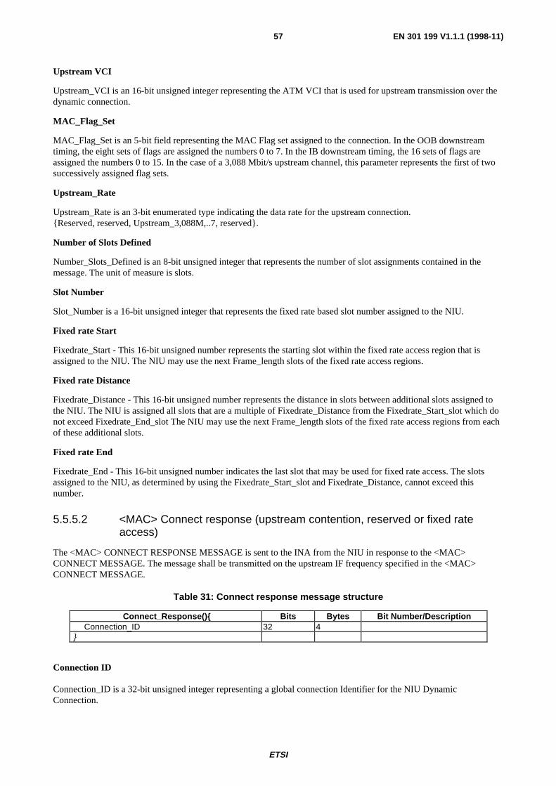
ETSI
EN 301 199 V1.1.1 (1998-11)57
Upstream VCI
Upstream_VCI is an 16-bit unsigned integer representing the ATM VCI that is used for upstream transmission over thedynamic connection.
MAC_Flag_Set
MAC_Flag_Set is an 5-bit field representing the MAC Flag set assigned to the connection. In the OOB downstreamtiming, the eight sets of flags are assigned the numbers 0 to 7. In the IB downstream timing, the 16 sets of flags areassigned the numbers 0 to 15. In the case of a 3,088 Mbit/s upstream channel, this parameter represents the first of twosuccessively assigned flag sets.
Upstream_Rate
Upstream_Rate is an 3-bit enumerated type indicating the data rate for the upstream connection.Reserved, reserved, Upstream_3,088M,..7, reserved.
Number of Slots Defined
Number_Slots_Defined is an 8-bit unsigned integer that represents the number of slot assignments contained in themessage. The unit of measure is slots.
Slot Number
Slot_Number is a 16-bit unsigned integer that represents the fixed rate based slot number assigned to the NIU.
Fixed rate Start
Fixedrate_Start - This 16-bit unsigned number represents the starting slot within the fixed rate access region that isassigned to the NIU. The NIU may use the next Frame_length slots of the fixed rate access regions.
Fixed rate Distance
Fixedrate_Distance - This 16-bit unsigned number represents the distance in slots between additional slots assigned tothe NIU. The NIU is assigned all slots that are a multiple of Fixedrate_Distance from the Fixedrate_Start_slot which donot exceed Fixedrate_End_slot The NIU may use the next Frame_length slots of the fixed rate access regions from eachof these additional slots.
Fixed rate End
Fixedrate_End - This 16-bit unsigned number indicates the last slot that may be used for fixed rate access. The slotsassigned to the NIU, as determined by using the Fixedrate_Start_slot and Fixedrate_Distance, cannot exceed thisnumber.
5.5.5.2 <MAC> Connect response (upstream contention, reserved or fixed rateaccess)
The <MAC> CONNECT RESPONSE MESSAGE is sent to the INA from the NIU in response to the <MAC>CONNECT MESSAGE. The message shall be transmitted on the upstream IF frequency specified in the <MAC>CONNECT MESSAGE.
Table 31: Connect response message structure
Connect_Response() Bits Bytes Bit Number/DescriptionConnection_ID 32 4
Connection ID
Connection_ID is a 32-bit unsigned integer representing a global connection Identifier for the NIU DynamicConnection.

ETSI
EN 301 199 V1.1.1 (1998-11)58
5.5.5.3 <MAC> Connect confirm (singlecast downstream)
The <MAC> Connect Confirm message is sent from the INA to the NIU. Its usage is recommended when INAvalidation of new connection is required.
Table 32: Connect confirm message structure
Connect_Confirm() Bits Bytes Bit Number / DescriptionConnection_ID 32 4
Connection ID
Connection_ID is a 32-bit unsigned integer representing a global connection Identifier for the NIU DynamicConnection.
5.5.6 Data connections
A connection is initiated by the INA using the <MAC> Connect Message explained in subclause 5.5.5.1. This messageis either used to immediately assign time slots for a fixed rate connection or just to assign a connection ID and relatedparameters without time slot assignment. In particular, for reservation or contention access, no time slots are assigned inthe Connect Message, but the connection ID shall be used in requests for slots by the NIU.
Connection assignment
The INA can assign other connections by using the <MAC> Connect message described previously. The NIU cannotrequest a connection, it shall be initiated by higher layers.
Connection release
This subclause defines the MAC signalling requirements for connection release. The figure below displays the signallingflow for releasing a connection. The NIU cannot release a connection, this shall be initiated by higher layers. Thismessage is thus initiated by the INA only.
1) Upon receiving the <MAC> Release Message from the INA, the NIU shall teardown the upstream connectionestablished for the particular.
2) Upon teardown of the upstream connection, the NIU shall send the <MAC> Release Response Message on thedefault upstream channel.
<MAC> ReleaseMessage
N R C
<MAC> ReleaseResponse
NIU/STB
Figure 31: Connection release signalling
<MAC> Release Message (Singlecast downstream)
The <MAC> Release Message is sent from the INA to the NIU to terminate a previously established connection.
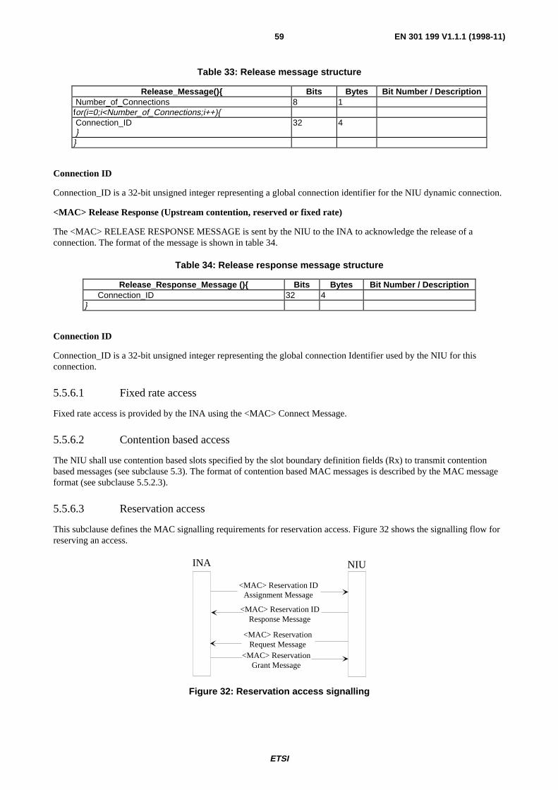
ETSI
EN 301 199 V1.1.1 (1998-11)59
Table 33: Release message structure
Release_Message() Bits Bytes Bit Number / Description Number_of_Connections 8 1for(i=0;i<Number_of_Connections;i++) Connection_ID
32 4
Connection ID
Connection_ID is a 32-bit unsigned integer representing a global connection identifier for the NIU dynamic connection.
<MAC> Release Response (Upstream contention, reserved or fixed rate)
The <MAC> RELEASE RESPONSE MESSAGE is sent by the NIU to the INA to acknowledge the release of aconnection. The format of the message is shown in table 34.
Table 34: Release response message structure
Release_Response_Message () Bits Bytes Bit Number / DescriptionConnection_ID 32 4
Connection ID
Connection_ID is a 32-bit unsigned integer representing the global connection Identifier used by the NIU for thisconnection.
5.5.6.1 Fixed rate access
Fixed rate access is provided by the INA using the <MAC> Connect Message.
5.5.6.2 Contention based access
The NIU shall use contention based slots specified by the slot boundary definition fields (Rx) to transmit contentionbased messages (see subclause 5.3). The format of contention based MAC messages is described by the MAC messageformat (see subclause 5.5.2.3).
5.5.6.3 Reservation access
This subclause defines the MAC signalling requirements for reservation access. Figure 32 shows the signalling flow forreserving an access.
INA NIU
<MAC> Reservation IDAssignment Message
<MAC> Reservation Request Message
<MAC> ReservationGrant Message
<MAC> Reservation IDResponse Message
Figure 32: Reservation access signalling
ETSI
EN 301 199 V1.1.1 (1998-11)60
1) The NIU shall wait for a <MAC> Reservation ID Assignment Message from the INA before it can requestreservation access. It shall respond with a <MAC> Reservation ID response Message.
2) At any time when needed after receiving the reservation ID, the NIU can request a certain number of slots to theINA using the <MAC> Reservation Request Message.
3) The INA shall respond to that message using the <MAC> Reservation Grant Message.
4) If the NIU has not received the <MAC> Reservation Grant Message before the Grant_Protocol_Timeout, it shallsend a <MAC> Reservation Status Request to the INA. This leads back to 3.
<MAC> Reservation ID assignment message (singlecast downstream)
The <MAC> Reservation ID Assignment Message is used to assign the NIU a Reservation_ID. The NIU identifies itsentry in the Reservation_grant_message by comparing the Reservation_ID assigned to it by theReservation_ID_assignment_message and the entries in the Reservation_Grant_message.
The format of the message is given in table 35.
Table 35: Reservation ID assignment message structure
Reservation_ID_assignment_Message () Bits Bytes Bit Number / DescriptionConnection_ID 32 4Reservation_ID 16 2Grant_protocol_timeout 16 2
Connection ID
Connection_ID is a 32-bit unsigned integer representing a global connection identifier for the NIU dynamic connection.
Reservation_ID
Reservation_ID is a 16-bit unsigned number representing a locally assigned identifier for the connection. This is used asa short identifier by the NIU to identify the appropriate Reservation_Grant_Messages.
Grant_protocol_timeout
Grant_protocol_timeout is a 16-bit unsigned number representing the time in milliseconds that the NIU should waitbefore verifying the status of pending grants. This parameter specifies the time that the NIU should wait after receivingthe last Reservation_grant_message, with an entry addressed to the NIU, before initiating a reservation status request. Ifthe NIU has pending grants and the timeout occurs, it should send the Reservation_status_request message to the INA.The INA will respond with the Reservation_grant_message (probably without granting any slots) to inform the NIU ofany remaining slots left to be granted. This allows the NIU to correct any problems should they exist such as issuing anadditional request for slots or waiting patiently for additional grants.
<MAC> Reservation ID Response Message
The MAC reservation ID response Message is used to acknowledge the receipt of the <MAC>Reservation_ID_Assignment message. The format of the message is given in table 36.
Table 36: Reservation ID Response Message
Reservation_ID_Response_Message () Bits Bytes Bit Number / DescriptionConnection_ID 32 4Reservation_ID 16 2
Connection_ID
Connection_ID is a 32-bit unsigned integer representing a global connection identifier for the NIU/STB dynamicconnection.

ETSI
EN 301 199 V1.1.1 (1998-11)61
Reservation_ID
Reservation_ID is a 16-bit unsigned number representing a locally assigned identifier for the connection. This is used asa short identifier by the NIU/STB to identify the appropriate Reservation_Grant_Messages.
<MAC> Reservation request message (upstream contention, fixed rate or reserved)
Table 37: Reservation request message structure
Reservation_Request_message () Bits Bytes Bit Number / DescriptionReservation_ID 16 2Reservation_request_slot_count 8 1
This message is sent from the NIU to the INA.
Reservation_ID
Reservation_ID is a 16-bit unsigned number representing a locally assigned identifier for the connection. This is used asa short identifier by the NIU to identify the appropriate Reservation_Grant_Messages.
Reservation Request Slot Count
Reservation_request_slot_count is an 8-bit unsigned number representing the number of slots requested by the NIU.This is the number of sequential slots that will be allocated in the reservation region of the upstream channel. The INAwill respond with the Reservation_Grant message granting the request.
<MAC> Reservation grant message (broadcast downstream)
The <MAC> RESERVATION GRANT MESSAGE is used to indicate to the NIU which slots have been allocated inresponse to the Reservation Request message. The NIU identifies its entry in the Reservation_grant_message bycomparing the Reservation_ID assigned to it by the Reservation_ID_assignment_message and the entries in theReservation_Grant_message.
The format of the message is given in table 38.
Table 38: Reservation grant message structure
Reservation_grant_message () Bits Bit Number/ DescriptionReference_slot 16Number_grants 8for (I=1; I<=Number_grants; I++)Reservation_ID 16Grant_Slot_count 4Remaining_slot_count 5Grant_control 2Grant_slot_offset 5
Reference_slot
Reference_slot is an 16-bit unsigned number indicating the reference point for the remaining parameters of this message.This represents a physical slot of the upstream channel. Since the upstream and downstream slots are not aligned, theINA shall send this message in a downstream slot such that it is received by the NIU before the Reference_slot exists onthe upstream channel.
Number_grants
Number_grants is an 8-bit unsigned number representing the number of grants contained within this message.

ETSI
EN 301 199 V1.1.1 (1998-11)62
Reservation_ID
Reservation_ID is a 16-bit unsigned number representing a locally assigned identifier for the connection. This is used asa short identifier by the NIU to identify the appropriate Reservation_Grant_Messages.
Grant_slot_count
Grant_slot_count is an 4-bit unsigned number representing the number of sequential slots currently granted for theupstream burst. Upon receipt of this message the NIU is assigned Grant_slot_count sequential slots in the reservationaccess region of the upstream channel starting at the position indicated by the Reference_slot and Grant_slot_offsetvalues. A value of zero indicates that no slots are being granted. This would typically be the case in a response to aReservation_status_request message.
Remaining_slot_count
Remaining_slot_count is a 5-bit unsigned number representing the remaining slots to be granted by the INA withsubsequent grant messages. A value of 0x1f indicates that 31 or more slots will be made available in the future. A valueof 0x0 indicates that no additional slots will be granted in the future and that the slots granted in this message representthe only remaining slots available for the connection. The NIU should monitor this count to determine if sufficient slotsremain to satisfy current needs. Should additional slots be required because of lost grant messages or additional demand,additional slots should be requested using the Reservation_request_message. Additional Reservation_request_messagesshall be sent only when the Remaining_slot_count is less than 15. To minimize contention on the upstream channel, theReservation_request_message may be sent in one of the slots granted by the Reservation_Grant_Message.
Grant_slot_offset
Grant_slot_offset is an 5-bit unsigned number representing the starting slot to be used for the upstream burst. Thisnumber is added to the Reference slot to determine the actual physical slot. Upon receipt of this message the NIU isassigned Grant_slot_count sequential slots in the reservation access region of the upstream channel.
<MAC> Reservation Status Request (Upstream contention, fixed rate or reserved)
The <MAC> RESERVATION STATUS REQUEST Message is used to determine the status of the outstanding grantsto be assigned by the INA. This message is only sent after the Grant protocol time-out is exceeded. The INA willrespond with the Reservation_grant_message (possibly without granting any slots) to inform the NIU of any remainingslots left to be granted. This allows the NIU to correct any problems should they exist such as issuing an additionalrequest for slots or waiting patiently for additional grants.
The format of the message is given in table 39.
Table 39: Reservation status request message structure
Reservation_Status_Request_Message () Bits Bytes Bit Number / DescriptionReservation_ID 16 2Remaining_request_slot_count 8 1
Reservation_ID
Reservation_ID is a 16-bit unsigned number representing a locally assigned identifier for the connection. This is used asa short identifier by the NIU to identify the appropriate Reservation_Grant_Messages.
Remaining_request_slot_count
Remaining_request_slot_count is an 8-bit unsigned number representing the number of slots that the NIU is expecting tobe granted.

ETSI
EN 301 199 V1.1.1 (1998-11)63
5.5.7 MAC link management
The MAC link management tasks provide continuous monitoring and optimization of upstream resources. Thesefunctions include:
- power and timing management;
- fixed rate allocation management;
- channel error management.
5.5.7.1 Power and timing management
Power and timing management shall provide continuous monitoring of upstream transmission from the NIU. The<MAC> Ranging and Power Calibration Message is used to maintain a NIU within predefined thresholds of powerand time.
The upstream burst demodulator shall continuously monitor the upstream burst transmissions from an NIU. Upondetection of an NIU outside the predefined range, the INA shall send the <MAC> Ranging and Power CalibrationMessage to the NIU.
5.5.7.2 TDMA allocation management
To ensure optimum assignment of TDMA resources, the INA shall ensure the upstream allocation of TDMA resourcesfor various connections remain intact when allocating resources to a new connection. However, in the event thatreconfiguration is required to minimize fragmentation of resources, then the INA shall dynamically reconfigure theupstream TDMA assignments to a NIU or group of NIUs. The <MAC> Reprovision Message is utilized to changepreviously established connection parameters.
<MAC> Reprovision message (singlecast downstream)
The <MAC> REPROVISION MESSAGE is sent by the INA to the NIU to reassign upstream resources (maintaining theoriginally requested QoS parameters at the establishment of the connection.) This message is intended for fixed ratebased channel maintenance by the INA to redistribute or reassign resources allocated to a NIU.

ETSI
EN 301 199 V1.1.1 (1998-11)64
Table 40: Reprovision message structure
Reprovision_Message () Bits Bytes Bit Number / Description Reprovision_Control_Field 8 1 Reserved 2 7-6 New_Downstream_IB_Frequency 1 5: no,yes New_Downstream_OOB_Frequency 1 4: no,yes New_Upstream_Frequency_Included 1 3: no,yes New_Frame_Length_Included 1 2: no,yes New_Cyclical_Assignment_Included 1 1: no,yes New_Slot_List_Included 1 0: no,yes if (Reprovision_Control_Field= New_Downstream_OOB_Frequency) New_Downstream_IB_Frequency (32) (4) if (Reprovision_Control_Field= New_Downstream_OOB_Frequency)
New_Downstream_OOB_Frequency (32) (4) DownStream_Type 8 1 New_Downstream_OOB_Frequency (32) (4) if (Reprovision_Control_Field= New_Frequency_Included)
New_Upstream_Frequency (32) (4) New_Upstream_Channel_Number 3 1 7:5 reserved 2 4:3 Upstream_Rate 3 2:0 MAC_Flag_Set 5 1 7:3 Reserved 3 2:0 New_Upstream_Frequency (32) (4) if (Connection_Control_Field= New_Frame_Size_Included) New_Frame_Length (16) (2) 9-0:
Unsigned if (Reprovision_Control_Field= New_Slot_List) Number_of_Connections (8) (1) for(i=0;i<Number_of_Connections;i++) Connection_ID (32) (1)if(Reprovision_Control_Field == new_slot_list_included)
Fixed Rate Access
Number_Slots_Defined (8) (1) for(i=0;i<Number_Slots_Assigned;i++) Slot_Number (16) (2) if (Reprovision_Control_Field ==new_cyclic_Assignment_included)
Fixed Rate Access
Fixedrate_Start (16) (2) Fixedrate_Dist (16) (2) Fixedrate_End (16) (2)
Reprovision Control Field
Reprovision_Control_Field specifies what modifications to upstream resources are included.
New Downstream OOB frequency
New_Upstream_OOB_Frequency is a boolean that indicates that a new downstream OOB IF frequency is specified inthe message.
New Downstream IB frequency
New_Upstream_IB_Frequency is a boolean that indicates that a new downstream IB IF frequency is specified in themessage.

ETSI
EN 301 199 V1.1.1 (1998-11)65
New Upstream frequency Included
New_Upstream_Frequency_Include is a boolean that indicates that a new upstream IF frequency is specified in themessage.
New Frame Length Included
New_Frame_Length_Include is a boolean that indicates that a new upstream frame is specified in the message.
New Slot List Included
New_Slot_List_Include is a boolean that indicates that a new slot list is specified in the message.
New Cyclical Assignment Included
New_Cyclical_Assignment_Include is a boolean that indicates that a new cyclical assignment is specified in themessage.
New Downstream Frequency
New_Downstream_IB_Frequency is a 32-bit unsigned integer representing the reassigned downstream IB carrier centrefrequency. The unit of measure is Hz.
New Downstream OOB Frequency
New_Downstream_OOB_Frequency is a 32-bit unsigned integer representing the reassigned downstream OOB carriercentre frequency. The unit of measure is Hz.
DownStream_Type is an 8-bit enumerated type indicating the modulation format for the down stream connection.reserved, reserved, QPSK_3,088, 3..255 reserved.
New Upstream Frequency
New_Upstream_Frequency is a 32-bit unsigned integer representing the reassigned upstream carrier centre IF frequency.The unit of measure is Hz.
UpstreamStream_Rate is an 3-bit enumerated type indicating the data rate for the upstream connection. Reserved,Reserved, Upstream_3,088M, 3..7 reserved.
MAC_Flag_Set is an 5-bit field representing the MAC Flag set assigned to the connection. In the OOB downstreamtiming, the eight sets of flags are assigned the numbers 0 to 7. In the IB downstream timing, the 16 sets of flags areassigned the numbers 0 to 15. This parameter represents the first of two successively assigned flag sets.
New Frame Length
New_Frame_Length is a 16-bit unsigned integer representing the size of the reassigned upstream Fixed rate basedframe. The unit of measure is in slots.
Number of Slots Defined
Number_Slots_Defined is an 8-bit unsigned integer that represents the number of slot assignments contained in themessage. The unit of measure is slots.
Slot Number
Slot_Number is a 16-bit unsigned integer that represents the fixed rate based slot number assigned to the NIU.

ETSI
EN 301 199 V1.1.1 (1998-11)66
5.5.7.3 Channel error management
During periods of connection inactivity, the NIU shall enter an idle mode. Idle mode is characterized by periodictransmission by the NIU of a <MAC> Idle Message. The idle mode transmission shall occur at a periodic rate sufficientfor the INA to establish Packet Error Rate statistics.
<MAC> Idle Message (Upstream fixed rate or reserved)
The <MAC> Idle Message is sent by the NIU within the STB to the INA at predefined intervals (between 1 and 10minutes) when upstream connection buffers are empty.
Table 41: Idle message structure
Idle_Message() Bits Bytes Bit Number / DescriptionIdle_Sequence_Count 8 1
Power_Control_Setting 8 1
Idle Sequence Count
Idle_Sequence_Count is a 8-bit unsigned integer representing the count of <MAC> IDLE MESSAGES transmittedwhile the NIU is Idle.
Power Control Setting
Power_Control_Setting is a 8-bit unsigned integer representing the absolute power attenuation that the NIU is using forupstream transmission.
5.5.7.4 Link management messages
<MAC> Transmission control message (singlecast or broadcast downstream)
The <MAC> TRANSMISSION CONTROL MESSAGE is sent to the NIU from the INA to control several aspects ofthe upstream transmission. This includes stopping upstream transmission, re-enabling transmission from a NIU or groupof NIUs and rapidly changing the upstream IF frequency being used by a NIU or group of NIUs. To identify a group ofNIUs for switching frequencies, the <MAC> TRANSMISSION CONTROL MESSAGE is sent in broadcast mode withthe Old_IF frequency included in the message. When broadcast with the Old_Frequency, the NIU shall compare itscurrent IF frequency value to Old_Frequency. When unequal, the NIU shall switch to the new IF frequency specified inthe message. When equal, the NIU shall ignore the new IF frequency and remain on its current channel.

ETSI
EN 301 199 V1.1.1 (1998-11)67
Table 42: Transmission control message structure
Transmission_Control_Message() Bits Bytes Bit Number / Description Transmission_Control_Field 8reserved 3 7-5:
Stop_Upstream_Transmission 1 4: no, yes Start_Upstream_Transmission 1 3: no, yes Old_Frequency_Included 1 2: no, yes Switch_Downstream_OOB_Frequency 1 1: no, yes Switch_Upstream_Frequency 1 0: no, yesif (Transmission_Control_Field==Switch_Upstream_Frequency &&Old_Frequency_Included) Old_Upstream_Frequency (32) (4)if (Transmission_Control_Field==Switch_Upstream_Frequency)
New_Upstream_Frequency (32) (4)New_Upstream_Channel_Number 3 1 7:5reserved 2 4:3Upstream_Rate 3 2:0MAC_Flag_Set 5 1 7:3Reserved 3 2:0New_Upstream_Frequency (32) (4)
if (Transmission_Control_Field==Switch_Downstream_OOB_Frequency &&Old_Frequency_Included)
Old_Downstream__OOB_Frequency (32) (4)if (Transmission_Control_Field== Switch_Downstream_OOB_Frequency)
New_Downstream_OOB_Frequency (32) (4)DownStream_Type 8 1
Transmission Control Field
Transmission_Control_Field specifies the control being asserted on the upstream channel.
Stop Upstream Transmission
stop_upstream_transmission is a boolean when set indicates that the NIU should halt its upstream transmission.
Start Upstream Transmission
start_upstream_transmission is a boolean when set indicates that the Network Interface Unit should resume transmissionon its upstream channel. The NIU shall respond to the ranging and power calibration message regardless of the setting ofthe start_upstream_transmission bit.
Old Frequency Included
Old_Frequency_Included is a boolean when set indicates that the Old IF frequency value is included in the message andshould be used to determine if a switch in IF frequency is necessary
Switch Downstream OOB Frequency
switch_downstream_OOB_frequency is a boolean when set indicates that a new downstream OOB IF frequency isincluded in the message.

ETSI
EN 301 199 V1.1.1 (1998-11)68
Switch Upstream Frequency
switch_upstream_frequency is a boolean when set indicates that a new upstream IF frequency is included in themessage. Typically, the switch_upstream_frequency and the stop_upstream_transmission are set simultaneously to allowthe NIU to stop transmission and change channel. This would be followed by the <MAC> TRANSMISSIONCONTROL MESSAGE with the start_upstream_transmission bit set.
Old Upstream Frequency
Old_Upstream_Frequency is a 32-bit unsigned integer representing the IF frequency that should be used by the NIU tocompare with its current IF frequency to determine if a change in channel is required.
New Upstream Frequency
New_Upstream_Frequency is a 32-bit unsigned integer representing the reassigned upstream IF carrier centre frequency.The unit of measure is Hz.
MAC_Flag_Set is an 5-bit field representing the MAC Flag set assigned to the connection. In the OOB downstreamtiming, the eight sets of flags are assigned the numbers 0 to 7. In the IB downstream timing, the 16 sets of flags areassigned the numbers 0 to 15. In the case of a 3,088 Mbit/s upstream channel, this parameter represents the first of twosuccessively assigned flag sets.
Upstream Stream_Rate is an 3-bit enumerated byte indicating the data rate for the upstream connection.reserved, reserved, Upstream_3,088M, 3..7 reserved.
Old downstream OOB Frequency
Old_Downstream_OOB_Frequency is a 32-bit unsigned integer representing the IF frequency that should be used by theNIU to compare with its current IF frequency to determine if a change in channel is required.
New downstream OOB Frequency
New_Downstream_OOB_Frequency is a 32-bit unsigned integer representing the reassigned downstream OOB carriercentre IF frequency. The unit of measure is Hz.
DownStream_Type is an 8-bit enumerated type indicating the modulation format for the down stream connection.reserved, reserved, QPSK_3,088, 3..255 reserved.
Link Management Response Message (Upstream contention, fixed rate or reserved)
The <MAC> LINK MANAGEMENT RESPONSE MESSAGE is sent by the NIU to the INA to indicate reception andprocessing of the previously sent Link Management Message. The format of the message is shown in table 43.
Table 43: Link management acknowledge message format
Link_Management_Acknowledge() Bits Bytes Bit Number / DescriptionLink_Management_Msg_Number 16 2
Link Management Message Number
Link_Management_Msg_Number is a 16-bit unsigned integer representing the previously received link managementmessage. The valid values for Link_Management_Msg_Number are shown in table 44.
Table 44: Link management message number
Message Name Link_Management_Msg_NumberTransmission Control Message Transmission Control Message Type ValueReprovision Message Reprovision Message Type Value

ETSI
EN 301 199 V1.1.1 (1998-11)69
<MAC> Status Request Message (downstream Singlecast)
The STATUS REQUEST message is sent by the INA to the NIU to retrieve information about the NIUs health,connection information and error states. The INA can request either the address parameters, error information,connection parameters or physical layer parameters from the NIU. The INA can only request one parameter type at atime to a particular NIU.
Table 45: Status request message structure
Status_Request() Bits Bytes Bit Number / Description Status_Control_Field 8 1 reserved 5 3-7: Status_Type 3 0-2: enum type
Status Control Field
Status_Control_Field is a 3-bit enumerated type that indicates the status information the NIU should return
enum Status_Control_Field Address_Params, Error_Params, Connection_Params, Physical_Layer_Params,reserved4..7;
<MAC> Status response message (upstream contention, fixed rate or reserved)
The <MAC> STATUS RESPONSE MESSAGE is sent by the NIU in response to the <MAC> STATUS REQUESTMESSAGE issued by the INA. The contents of the information provided in this message will vary depending on therequest made by the INA and the state of the NIU. The message shall be dissociated into separate messages if theresulting length of the message exceeds 40 bytes.

ETSI
EN 301 199 V1.1.1 (1998-11)70
Table 46: Status response message structure
Status_Response() Bits Bytes Bit Number/ Description NIU_Status 32 4 Response_Fields_Included 8 1 reserved 4 4-7: Address_Params_Included 1 3: no,yes Error_Information_Included 1 2: no,yes Connection_Params_Included 1 1: no,yes Physical_Layer_Params_Included 1 0: no,yes if (Response_Fields_Included == Address_Params_Included) NSAP_Address (160) (20) MAC_Address (48) (6) if (Response_Fields_Included == Error_Information_Included) Number_Error_Codes_Included (8) (1) for(i=0;i<Number_Error_Codes_Included; i++) Error_Param_code (8) (1) Error_Param_Value (16) (2) if (Response_Fields_Included == Connection_Params_Included) Number_of_Connections (8) (1) for(i=0;i<Number_of_Connections;i++) Connection_ID (32) (4) if (Response_Fields_Included == Physical_Layer_Params_Included) Power_Control_Setting (8) (1) Time_Offset_Value (32) (4) Upstream_Frequency (32) (4) Downstream_Frequency (32) (4)
NIU Status
NIU_Status is a 32-bit unsigned integer that indicates the current state of the NIU.
NIU_Status Calibration_Operation_Complete,Default_Connection_Established,
Network_Address_Registered,reserved;
Response Fields Included
Response_Fields_Included is an 8-bit unsigned integer that indicates what parameters are contained in the upstreamstatus response.
NSAP Address
NSAP_Address is a 20 byte address assigned to the NIU.
MAC Address
MAC_Address is a 6 byte address assigned to the NIU.

ETSI
EN 301 199 V1.1.1 (1998-11)71
Number of Error Codes Included
Number_Error_Codes_Included is an 8-bit unsigned integer that indicates the number of error codes are contained in theresponse.
Error Parameter Code
Error_Parameter_Code is a 8-bit unsigned integers representing the type of error reported by the NIU.
Table 47: Error Parameter Code
Error Parameter Code Name Error Parameter CodeFraming_Bit_Error_Count 0x00Slot_Configuration_CRC_Error_Count 0x01Reed_Solomon_Error_Count 0x02ATM_Packet_Loss_Count 0x03
Error Parameter Value
Error_Parameter_Value is an 16-bit unsigned integers representing error counts detected by the NIU.
Number of Connections
Number_of_Connections is an 8-bit unsigned integer that indicates the number of connections that are specified in theresponse. Specifically, if the number of connections is too large to have a MAC message with less than 40 bytes, it ispossible to send separate messages with only the number of connections indicated in each message.
Connection ID
Connection_ID is a 32-bit unsigned integer representing the global connection Identifier used by the NIU for thisconnection.
Power Control Setting
Power_Control_Setting is a 8-bit unsigned integer representing the absolute power attenuation that the NIU is using forupstream transmission.
Time Offset Value
Time_Offset_Value is a 16-bit short integer representing a relative offset of the upstream transmission timing. Anegative value indicates an adjustment forward in time. A positive value indicates an adjustment back in time. The unitof measure is 100 ns.
Upstream Frequency
Upstream_Frequency is a 32-bit unsigned integer representing the IF frequency assigned to the connection. The unit ofmeasure is in Hz.
Downstream Frequency
Downstream_Frequency is a 32-bit unsigned integer representing the IF frequency where the connection resides.The unit of measure is in Hz.

ETSI
EN 301 199 V1.1.1 (1998-11)72
BibliographyThe following material, though not specifically referenced in the body of the present document, gives supportinginformation.
DVB-A008: "Commercial requirements for asymmetric interactive services supporting broadcast to the home withnarrow-band return channels".
DAVIC 1.0 Specification: "DAVIC System Reference Model".

ETSI
EN 301 199 V1.1.1 (1998-11)73
History
Document history
V1.1.1 January 1998 Public Enquiry PE 9820: 1998-01-16 to 1998-05-15
V1.1.1 June 1998 Vote V 9837: 1998-07-14 to 1998-09-11
V1.1.1 November 1998 Publication
ISBN 2-7437-2546-XDépôt légal : Novembre 1998