tps especificacoes bosch sensors_throttleposition
TRANSCRIPT

8/17/2019 TPS Especificacoes BOSCH Sensors_throttleposition
http://slidepdf.com/reader/full/tps-especificacoes-bosch-sensorsthrottleposition 1/3
BB14 MOTORSPORT COMPONENTS
THROTTLE POSITION SENSORS
THROTTLE POSITION SENSOR TECHNICAL DATA
Purpose and Function.
Modern engine management systems require detailed information aboutthrottle position and rate of change. As many vehicle systems are influencedby throttle activity including fuelling requirements, transmission controlstrategy and accessories such as air conditioning accurate data is essen-tial, a simple switch cannot provide this detail.The sensors described below are full range sensors capable of operat-ing in clockwise or anti-clockwise directions and are compact for fitment inrestricted spaces.
For more detailed information about these products refer to our website
www.bosch.com.au
Electrical Direction
Measurement Operating Drive of Max. Circuit
Part Number Range Voltage Connector Type Rotation Current Figure
0 280 122 001 < 86º 5.0 1 237 000 039 "D" Optional < 18 uA A
0 261 211 003 < 93º 5.0 Non-Bosch Dual "V" C/Clockwise < 10 mA B
0 261 211 004 < 93º 5.0 Non-Bosch Dual "V" Clockwise < 10 mA B
Details of sensor 0 280 122 001 (fig. A)
Characteristic curve 1.A Internal stop, L Positional tolerance of the wiper whenfitted, N Nominal characteristic curve, T Tolerance limit.
Image of sensor 0 261 211 003 / 4 (fig. B)

8/17/2019 TPS Especificacoes BOSCH Sensors_throttleposition
http://slidepdf.com/reader/full/tps-especificacoes-bosch-sensorsthrottleposition 2/3
8 Angular-position sensors A B
Throttle-valve angular-position sensorMeasurement of angles up to 88°
00
0,05
0,941,00
Angle of rotationϕ
V o l t a g e r a t i o
N
T
1096
100°
w
A A
L
U A
U V
ϕ
Angle of rotationϕ
wϕ 30 60 90°230
00,05
0,40
0,60
0,80
0,91251,00
0,20
A A
V o l t a g e r a t i o
U A
U V
2 3
88
Characteristic curve 1.A Internal stop, L Positional tolerance of the
wiper when fitted, N Nominal characteristic
curve, T Tolerance limit,
W Electrically usable angular range.
Characteristic curves 2 and 3.A Internal stop,
W Electrically usable angular range.
Technical data / Range
Part number 0 280 122 001 0 280 122 201Diagram 1; 2 3Useful electrical angular range Degree ≤ 86 ≤ 88Useful mechanical angular range Degree ≤ 86 ≤ 92
Angle between the internal stops(must not be contacted whensensor installed) Degree ≥ 95 –
Direction of rotation Optional CounterclockwiseTotal resistance (Terms. 1–2) kΩ 2 ±20 % –Wiper protective resistor (wiper
in zero setting, Terms. 2–3) Ω 710...1380 –Operating voltage U V V 5 5Electrical loading Ohmic resistance Ohmic resistancePermissible wiper current µA ≤ 18 ≤ 20Voltage ratio from stop to stop
Chara. curve 1 0.04 ≤ U A/U V ≤ 0.96 –Voltage ratio in area 0...88 °C
Chara. curve 2 – 0.05 ≤ U A2/U V ≤ 0.985Chara. curve 3 – 0.05 ≤ U A3/U V ≤ 0.970
Slope of the nominal characteristic curve deg–1
0.00927 –Operating temperature °C –40...+130 –40...+85Guide value for permissible vibration
acceleration m · s–2 ≤ 700 ≤ 300Service life (operating cycles) Mio 2 1.2
ApplicationThese sensors are used in automotiveapplications for measuring the angle ofrotation of the throttle valve. Since thesesensors are directly attached to the throttle-valve housing at the end of the throttle-shaft extension, they are subject to ex-tremely hostile underhood operating con-ditions. To remain fully operational, theymust be resistant to fuels, oils, saline fog,and industrial climate.
Design and functionThe throttle-valve angular-position sensoris a potentiometric sensor with a linearcharacteristic curve. In electronic fuelinjection (EFI) engines it generates avoltage ratio which is proportional to thethrottle valve’s angle of rotation. Thesensor’s rotor is attached to the throttle-valve shaft, and when the throttle valvemoves, the sensor’s special wipers moveover their resistance tracks so that thethrottle’s angular position is transformedinto a voltage ratio. The throttle-valveangular-position sensor’s are not providedwith return springs.
DesignThe position sensor 0 280 122 001 hasone linear characteristic curve.The position sensor 0 280 122 201 hastwo linear characteristic curves.This permits particularly good resolution inthe angular range 0°...23°.
Explanation of symbolsU A Output voltageU V Supply voltage Angle of rotationU A2 Output voltage, characteristic curve 2U A3 Output voltage, characteristic curve 3
Accessories for 0 280 122 001Connector 1 237 000 039
Accessories for 0 280 122 201Plug housing 1 284 485 118Receptacles, 5 per pack,Qty. required: 4 1 284 477 121Protective cap, 5 per pack,Qty. required: 1 1 280 703 023
R
Potentiometic angular-position sensor with linearcharacteristic curve. Sturdy construction forextreme loading. Very compact.
8/17/2019 TPS Especificacoes BOSCH Sensors_throttleposition
http://slidepdf.com/reader/full/tps-especificacoes-bosch-sensorsthrottleposition 3/3
1 1
6 -0,1
0 , 5 1
3 , 5
+ 1
- 0 , 3
M4
0,130,5 ± 0,124,5 ±
M42,3
m i n . ø
2 1
176° ±2°
2
- 0 , 1
0
+ 0 , 0
2
4,5± 0,1 5
R 6 , 5
3
8
1 6
ø 1 5 , 1
3 5
1 3
55 ±0,2
68
ø 1 5 , 1
D 1 0
ø 8
- 0 , 0
5
13
+ 0 , 2
- 0 , 1 x 4 5 °
± 0 , 5
55±0,2
9 0 ° ± 2 °
A
B
C
D E
Ö Ö
Ö
2 M 4
9 0 ° ± 2
, 8 °
1
2,5 -0,5
7,5
8,5
3 0 °
ø 2 5 m i n .
1+0,2
4,5
ø 2 0 , 5
ø 2 1
7,5
R 4
4,8+ 0,3
1 4 ° + 2 °
- 1 °
10,5
5 9
±
0 , 3
h 1 0
±0,3
5 4
7
22
2 0
3 9
6
7
85
70 ± 0,2
ø 2 1 D 1 0
ø 8
- 0 , 0
5
4
± 0 , 0
5
± 0 , 2 x 4 5 °
70 ± 0,2
F
G
H
I
4321
L
X
K
X
1 °
7 ° ±
M 4
9,7
±0,1
3 5
3 0 , 5
± 0 , 1
2 ± 0,2
4,6 ±0,3
16
A
B
31 2
B A Angular-position sensors 9
3 2 1( - )( + )
3 2 1( - ) ( + )
S2 S1
4 3 2 1
( ) ( )
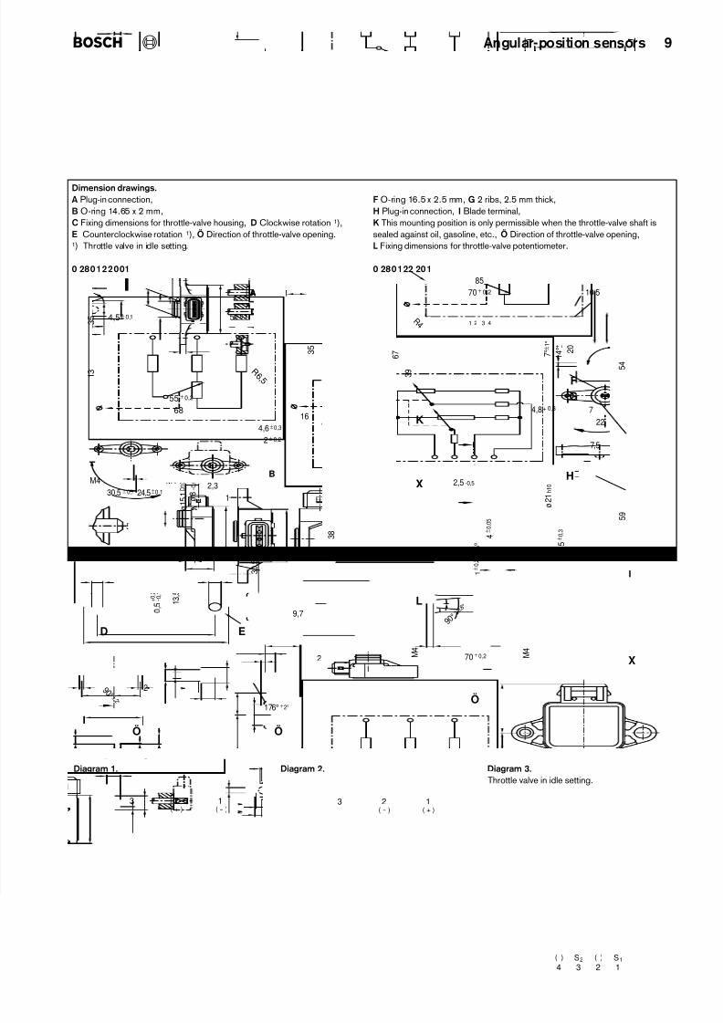
Dimension drawings.A Plug-in connection,
B O-ring 14.65 x 2 mm,
C Fixing dimensions for throttle-valve housing, D Clockwise rotation 1),
E Counterclockwise rotation 1), Ö Direction of throttle-valve opening.1) Throttle valve in idle setting.
0 280122001
F O-ring 16.5 x 2.5 mm, G 2 ribs, 2.5 mm thick,
H Plug-in connection, I Blade terminal,
K This mounting position is only permissible when the throttle-valve shaft is
sealed against oil, gasoline, etc., Ö Direction of throttle-valve opening,
L Fixing dimensions for throttle-valve potentiometer.
0 280122 201
Diagram 1. Diagram 2. Diagram 3.Throttle valve in idle setting.