touch through metal · 2011-02-23 · metal flashing on the underside of the plastic cover. this...
TRANSCRIPT
1
© 2010 Microchip Technology Incorporated. All Rights Reserved. Touc h Through Metal Slide 1
Touch Through Metal
mTouch™ Metal Over Capacitive Technology
Part 1
Hello and welcome to Microchip’s Touch Through Metal presentation, part 1.
2
© 2010 Microchip Technology Incorporated. All Rights Reserved. Touc h Through Metal Slide 2
Introduction & Agenda
� Presenter− Keith Curtis Technical Staff Engineer
� Subject− Implementing capacitive touch through a
metal cover� Approximately 25 minutes � This presentation is an introduction to
metal over capacitive� This presentation includes the
mechanical design section
My name is Keith Curtis and I am a Technical Staff Engineer for Microchip.
Today we will be talking about implementing a capacitive touch system that operates through a metal cover.
We will be talking approximately 25 minutes about both the basic system overview and the requirements for a successful mechanical design.
Part 2 of the presentation will cover the electrical and firmware portion of the design.
3
© 2010 Microchip Technology Incorporated. All Rights Reserved. Touc h Through Metal Slide 3
Training Objectives
At the end of the presentation, the student should:• Understand the strengths of different
methods for detecting a user's touch through metal
• Understand the basic principals behind a metal over Capacitive touch system
• Understand the requirements for a successful mechanical design
Our first objective today will be explaining the various touch through metal technologies available today, and their strengths and their limitations.
Next we will discuss the basic principals behind Microchip’s Metal over Capacitive touch system.
And, finally, we will discuss the requirements for a successful mechanical design.

4
© 2010 Microchip Technology Incorporated. All Rights Reserved. Touc h Through Metal Slide 4
Why Touch Through Metal?
� Easy to Clean− Medical & Food Prep
� Sealed User Interface− Dust, Moisture, & Chemicals
� Wear Resistance & Reliability � Requires an Actuation Force
− Gloves, Fingernails, Braille & Stylus� Stylish Look & Feel
The first question that is typically asked, is “why touch through metal?”
Well, there are several good reasons:
1. It is very easy to clean, making it a preferred interface option for both medical and food preparation.
2. It is sealed so dust, moisture, and chemicals are locked out of sensitive internal electronics.
3. The interface is very robust with both exceptional reliability and wear resistance.
4. The requirement for an actual actuation force, rather than just the presence of the user’s finger, opens up the interface for gloves, fingernails, and a stylus for actuation the button.This also allows the system to be used in Braille applications for visually impaired users.
5. Finally, the stylish look and feel of a metal finish for the user interface is visually appealing to customers.

5
© 2010 Microchip Technology Incorporated. All Rights Reserved. Touc h Through Metal Slide 5
Competing Technology 1
� Piezo Sensors− First touch through metal
technology− Custom Piezo sensors− Requires analog front end
� Challenges− Sensor cost − Interface complexity− Adhering sensors to metal
OK, so touch through metal has several advantages, but aren’t there other technologies that accomplish the same thing?
Yes, there are couple of alternatives. One is Piezo sensors which mount behind the front panel. These sensors generate a positive pulse when the sensor is flexed by the user’s press, and a negative pulse when released.
While these were the first sensors designed to work through metal, they do have some limitations and challenges in their implementation:
1. The sensor cost is significant.
2. The analog circuitry to monitor the sensors is complex.
3. Adhesion of the sensors to the metal cover requires a special adhesive.
4. The sensors do not provide steady state information on the press of the sensor.
6
© 2010 Microchip Technology Incorporated. All Rights Reserved. Touc h Through Metal Slide 6
Competing Technology 2
� Inductive Touch − Second touch through
metal technology− Simple spiral inductor
sensors− Requires analog front end
� Challenges− Current consumption− Interface complexity− Mechanical design
The next alternative is Microchip’s inductive touch technology. This technology uses an inductive coil sensor behind the metal cover, sensing then the spacing between the cover and the coil changes due to deflection from a user’s press.
It does have an advantage over the Piezo system in that the sensors are significantly less expensive than the Piezo system. It also provides a steady state indication of the deflection in the metal cover.
However, the system still requires a fairly complex analog front end and special adhesives to bond the sensor PCB to the metal cover.
In addition, the sensing circuitry does draw 10s of milli amps to sense the movement of the metal cover.

7
© 2010 Microchip Technology Incorporated. All Rights Reserved. Touc h Through Metal Slide 7
Competing Technology 3
� Metal Over Capacitive− Third touch through metal
technology− Simple pad sensor− Requires simple
ADC/CVD/CTMU interface− Low power
� Challenges− Mechanical design
Microchip’s Metal over Capacitive actually requires very little in the way of interface electronics, requiring only an ADC or CTMU to perform the actual conversion on the sensor.
The sensor design is just a button shaped pad suspended below the metal cover, and the power requirements are only minimally higher than a traditional capacitive touch system.
The system does require careful mechanical design to achieve low button press pressures; however, the design is not any more complex than the Piezo or Inductive touch system.

8
© 2010 Microchip Technology Incorporated. All Rights Reserved. Touc h Through Metal Slide 8
Theory of Operation
Let’s talk now about the actual operation of the metal over capacitive touch system.
9
© 2010 Microchip Technology Incorporated. All Rights Reserved. Touc h Through Metal Slide 9
Theory of Operation
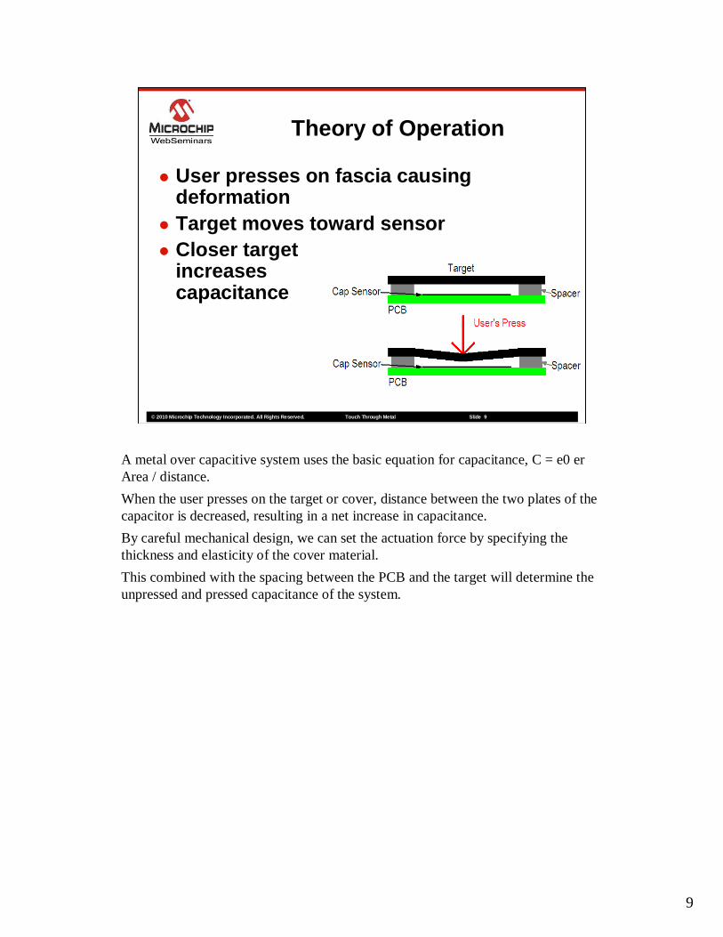
� User presses on fascia causing deformation
� Target moves toward sensor� Closer target
increases capacitance
A metal over capacitive system uses the basic equation for capacitance, C = e0 er Area / distance.
When the user presses on the target or cover, distance between the two plates of the capacitor is decreased, resulting in a net increase in capacitance.
By careful mechanical design, we can set the actuation force by specifying the thickness and elasticity of the cover material.
This combined with the spacing between the PCB and the target will determine the unpressed and pressed capacitance of the system.
10
© 2010 Microchip Technology Incorporated. All Rights Reserved. Touc h Through Metal Slide 10
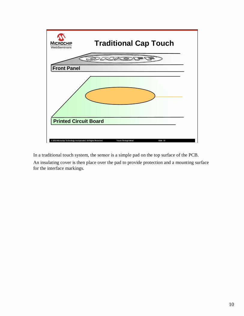
Traditional Cap Touch
Printed Circuit Board
Front Panel
In a traditional touch system, the sensor is a simple pad on the top surface of the PCB.
An insulating cover is then place over the pad to provide protection and a mounting surface for the interface markings.
11
© 2010 Microchip Technology Incorporated. All Rights Reserved. Touc h Through Metal Slide 11
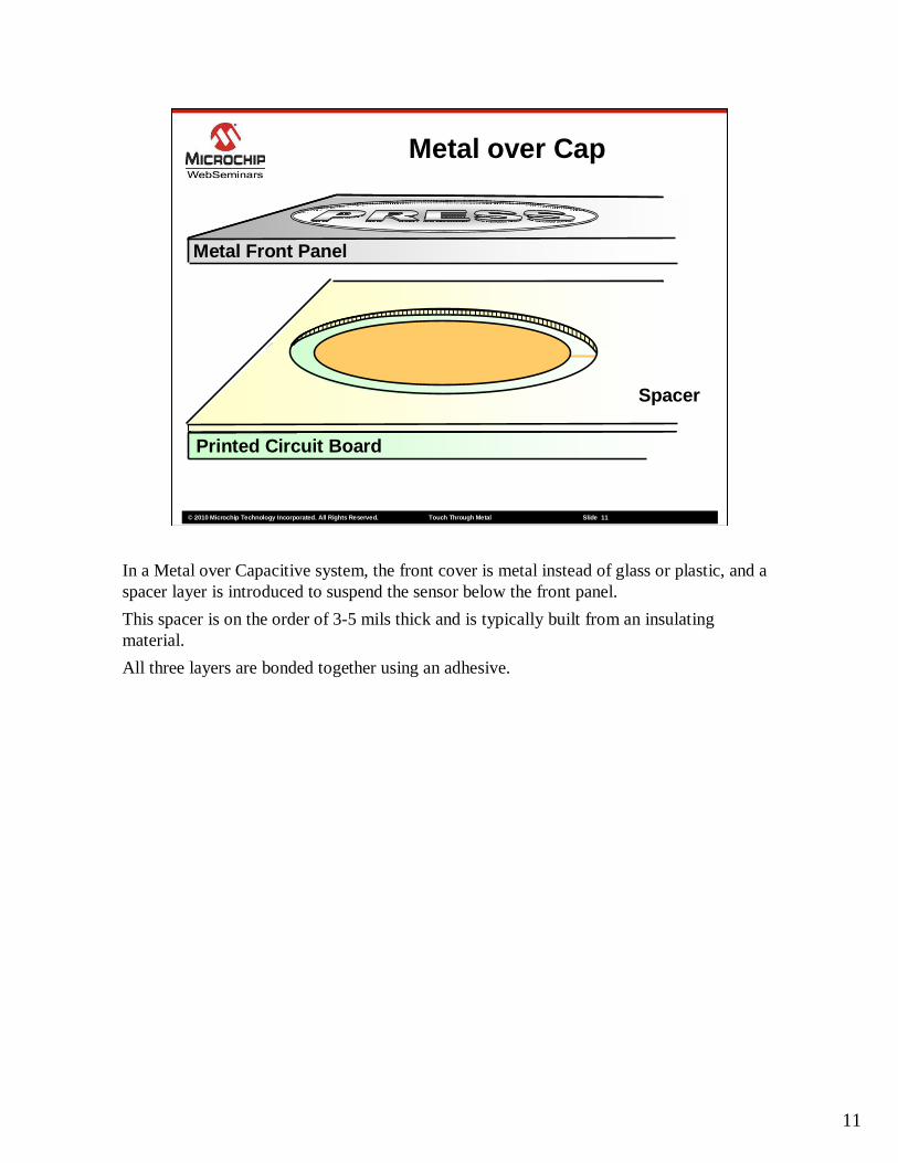
Metal over Cap
Printed Circuit Board
Spacer
Metal Front Panel
In a Metal over Capacitive system, the front cover is metal instead of glass or plastic, and a spacer layer is introduced to suspend the sensor below the front panel.
This spacer is on the order of 3-5 mils thick and is typically built from an insulating material.
All three layers are bonded together using an adhesive.
12
© 2010 Microchip Technology Incorporated. All Rights Reserved. Touc h Through Metal Slide 12
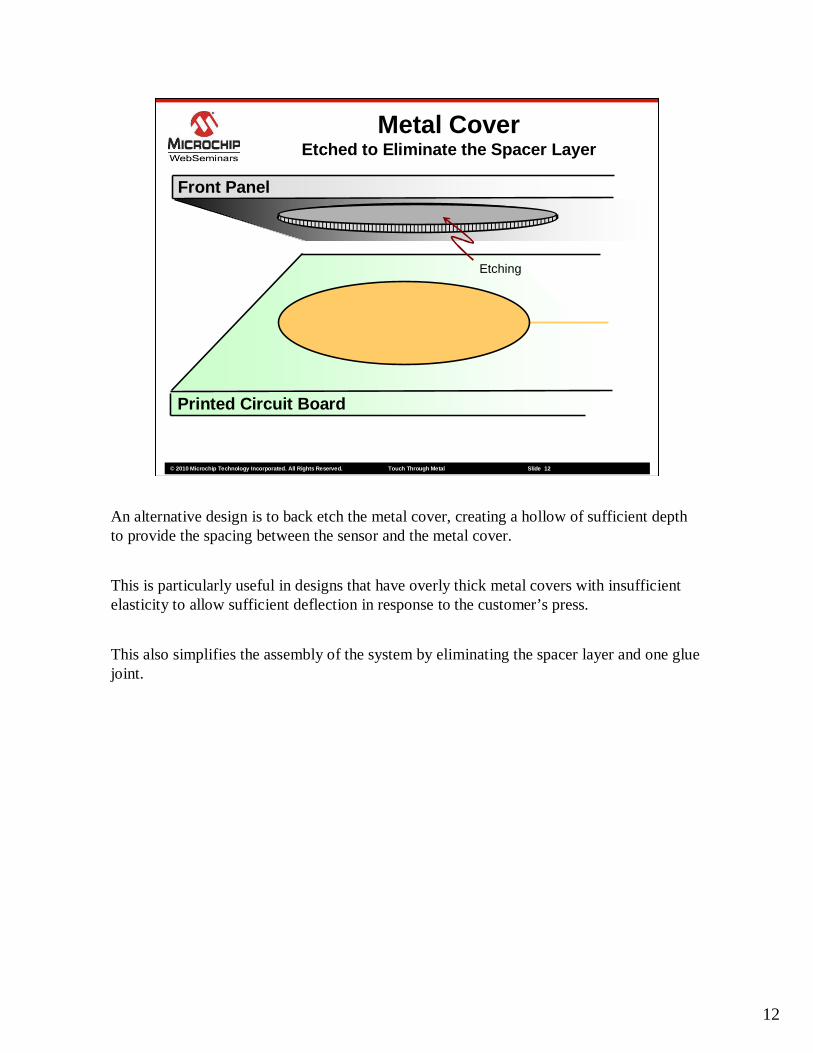
Metal CoverEtched to Eliminate the Spacer Layer
Printed Circuit Board
Front Panel
Etching
An alternative design is to back etch the metal cover, creating a hollow of sufficient depth to provide the spacing between the sensor and the metal cover.
This is particularly useful in designs that have overly thick metal covers with insufficient elasticity to allow sufficient deflection in response to the customer’s press.
This also simplifies the assembly of the system by eliminating the spacer layer and one glue joint.
13
© 2010 Microchip Technology Incorporated. All Rights Reserved. Touc h Through Metal Slide 13
Plastic CoverSpacer Part of the Molding
Printed Circuit Board
Front Panel
Metal Flashing
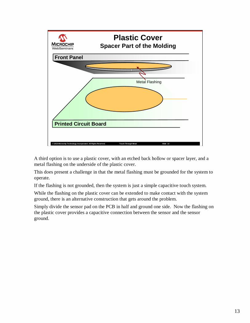
A third option is to use a plastic cover, with an etched back hollow or spacer layer, and a metal flashing on the underside of the plastic cover.
This does present a challenge in that the metal flashing must be grounded for the system to operate.
If the flashing is not grounded, then the system is just a simple capacitive touch system.
While the flashing on the plastic cover can be extended to make contact with the system ground, there is an alternative construction that gets around the problem.
Simply divide the sensor pad on the PCB in half and ground one side. Now the flashing on the plastic cover provides a capacitive connection between the sensor and the sensor ground.
14
© 2010 Microchip Technology Incorporated. All Rights Reserved. Touc h Through Metal Slide 14
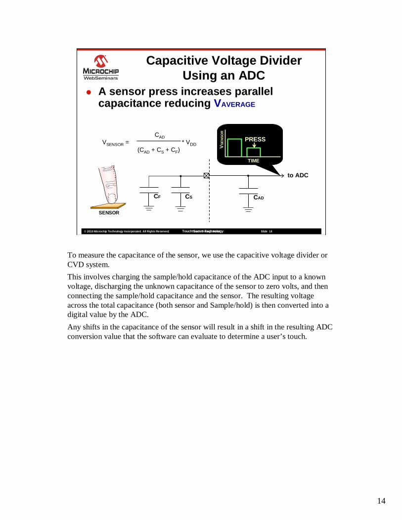
� A sensor press increases parallel capacitance reducing VAVERAGE
Capacitive Voltage Divider Using an ADC
CADVSENSOR = * VDD
(CAD + CS + CF)
SENSOR
CSCF CAD
to ADC
TIME
VS
EN
SO
R
PRESS
Touch Sense Technology
To measure the capacitance of the sensor, we use the capacitive voltage divider or CVD system.
This involves charging the sample/hold capacitance of the ADC input to a known voltage, discharging the unknown capacitance of the sensor to zero volts, and then connecting the sample/hold capacitance and the sensor. The resulting voltage across the total capacitance (both sensor and Sample/hold) is then converted into a digital value by the ADC.
Any shifts in the capacitance of the sensor will result in a shift in the resulting ADC conversion value that the software can evaluate to determine a user’s touch.
15
© 2010 Microchip Technology Incorporated. All Rights Reserved. Touc h Through Metal Slide 15
The Mechanical Design
As we mentioned earlier, this first presentation will also include the requirements for a successful mechanical design for a metal over capacitice touch system.

16
© 2010 Microchip Technology Incorporated. All Rights Reserved. Touc h Through Metal Slide 16
Mechanical Deflection
Second Moment of Area (I) = (L x T 3)/12Deflection (D) = (W x L 3 x K1)/(192 x E x I)Young’s Modulus (E) Etching Factor K1
Stainless 2.0 x 10 11 No Etch 1.225Aluminum 7.0 x 10 10 Spiral 3.370Mild Steel 2.1 x 10 11 Showerhead 22.000Polycarbonate 2.8 x 10 9 Pattern 3.550ABS plastic 2.4 x 10 9 (33% skin thickness)
A metal over capacitive touch system relies on the sufficient deflection of the cover material to cause a measurable shift in capacitance.
Typically the deviation must be a minimum of 5 microns for accurate touch detection.
To create a button with the right actuation force, it is necessary to understand the physics behind the deflection of the cover.
If we consider a circular section of the metal cover, which is the diameter of the opening spacer layer, we can model the deflection using the equations shown here.
The amount of force required to create a deflection of 5 microns is determined by:
1. The dimensions of the plate, both the diameter L and the thickness T
2. The Young’s modulus of the material
3. And, any etching on the backside of the plate.
The first value is the second moment of area, which is determined by the physical size and shape of the cover.
The second value is the actual deflection in response to touch pressure by the user. This is determined by the Second Moment of are, the Young’s modulus of the material, back etching and a proportionality constant of 192, which is determined by the shape of the section. 192 is the constant for a circular section and is the only practical shape for a simple analysis.
17
© 2010 Microchip Technology Incorporated. All Rights Reserved. Touch Thr ough Metal Slide 17
Elasticity of the Target
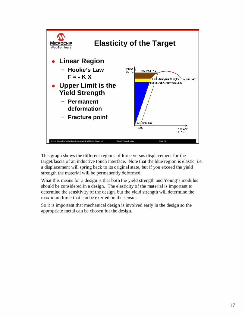
� Linear Region− Hooke’s Law
F = - K X
� Upper Limit is the Yield Strength− Permanent
deformation− Fracture point
This graph shows the different regions of force versus displacement for the target/fascia of an inductive touch interface. Note that the blue region is elastic, i.e. a displacement will spring back to its original state, but if you exceed the yield strength the material will be permanently deformed.
What this means for a design is that both the yield strength and Young’s modulus should be considered in a design. The elasticity of the material is important to determine the sensitivity of the design, but the yield strength will determine the maximum force that can be exerted on the sensor.
So it is important that mechanical design is involved early in the design so the appropriate metal can be chosen for the design.
© 2010 Microchip Technology Incorporated. All Rights Reserved. Touc h Through Metal Slide 18
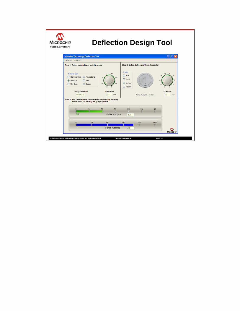
Deflection Design Tool

© 2010 Microchip Technology Incorporated. All Rights Reserved. Touc h Through Metal Slide 19
15mm Sensor Versus Spacer Thickness
Capacitance 15mm
0
50
100
150
200
250
300
3505 15 25 35 45 55 65 75 85 95 105
115
125
135
145
155
165
175
185
195
205
Capacitance in pF
Spacer Thickness in um
© 2010 Microchip Technology Incorporated. All Rights Reserved. Touc h Through Metal Slide 20
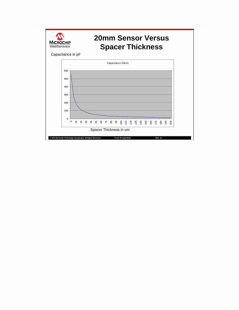
20mm Sensor Versus Spacer Thickness
Capacitance in pF
Spacer Thickness in um
Capacitance 20mm
0
100
200
300
400
500
6005 15 25 35 45 55 65 75 85 95 105
115
125
135
145
155
165
175
185
195
205
© 2010 Microchip Technology Incorporated. All Rights Reserved. Touc h Through Metal Slide 21
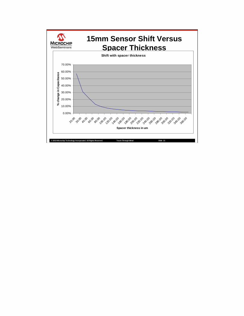
15mm Sensor Shift Versus Spacer Thickness
Spacer thickness in um
Shift with spacer thickness
0.00%
10.00%
20.00%
30.00%
40.00%
50.00%
60.00%
70.00%
20.00
30.0
040
.00
60.0
080
.00
100.0
0
120.0
0
140.0
0
160.0
0
180.0
0
200.0
0
220.0
0
240.0
0
260.0
0
280.0
0
300.0
0
320.0
0
340.0
0
360.0
0
Spacer thickness in um
% c
hang
e in
Cap
aci
tanc
e
22
What if not possible???

© 2010 Microchip Technology Incorporated. All Rights Reserved. Touc h Through Metal Slide 23
Continued in Part 2
� Implementing a capacitive touch through a metal cover hardware solution
� Implementing a capacitive touch through a metal cover software solution
� Handling noise considerations in the electrical and software design
© 2010 Microchip Technology Incorporated. All Rights Reserved. Touc h Through Metal Slide 24
Summary
� This presentation provided a general overview of metal over capacitive
� This presentation also covered the mechanical design of a metal over capacitive system
� This presentation is continued in the next metal over capacitive webinar
� Please provide feedback on this training session through Microchip’s website
© 2010 Microchip Technology Incorporated. All Rights Reserved. Touc h Through Metal Slide 25
Where to Get More Information
� Weblinks− mTouch™ Design Center
www.microchip.com/mTouch
� Application Notes− AN1325 - mTouch Metal Over Cap
Technology − AN1298 - Capacitive Touch Using Only an
ADC (CVD)

© 2010 Microchip Technology Incorporated. All Rights Reserved. Touc h Through Metal Slide 26
Trademarks
The Microchip name and logo, the Microchip logo, ds PIC, KeeLoq, KeeLoq logo, MPLAB, PIC, PICmicro, PICSTART, PIC 32 logo, rfPIC and UNI/O are registered trademarks of Microchip Technology Incorporated in the U.S.A. and other countries.FilterLab, Hampshire, HI-TECH C, Linear Active Ther mistor, MXDEV, MXLAB, SEEVAL and The Embedded Control Solutions Company a re registeredtrademarks of Microchip Technology Incorporated in the U.S.A.Analog-for-the-Digital Age, Application Maestro, Co deGuard, dsPICDEM, dsPICDEM.net, dsPICworks, dsSPEAK, ECAN, ECONOMONIT OR, FanSense, HI-TIDE, In-Circuit Serial Programming, ICSP, Mindi, M iWi, MPASM, MPLAB Certified logo, MPLIB, MPLINK, mTouch, Octopus, Omniscient Co de Generation, PICC, PICC-18, PICDEM, PICDEM.net, PICkit, PICtail, REAL ICE, rfLAB, Select Mode, Total Endurance, TSHARC, UniWinDriver, WiperLock an d ZENA are trademarks of Microchip Technology Incorporated in the U.S.A. and other countries.SQTP is a service mark of Microchip Technology Inco rporated in the U.S.A.All other trademarks mentioned herein are property of their respective companies.© 2010, Microchip Technology Incorporated, All Right s Reserved.