addendum #1 - sjeccd 1 artik... · end of addendum #1 addendum #2. artik art & architecture 07...
TRANSCRIPT

ARTIK ART AND ARCHITECTURE ADDENDUM #1 May 14, 2015
PAGE 1 OF 3
ADDENDUM #1
SAN JOSE CITY COLLEGE BLDG. 200 ALTERATION
IRONWORKER’S TRAINING CENTER
FOR
SAN JOSE-EVERGREEN COMMUNITY COLLEGE DISTRICT
Prepared by Architect
Artik Art and Architecture 394-A Umbarger Road
San Jose, Ca 95127 (408) 224-9890
This Addendum forms a part of the Contract Documents and modifies the original bidding documents dated February 18, 2014, as noted below. Bidders must acknowledge receipt of this Addendum in the space provided on the Bid Form. Failure to do so may subject the Bidder to disqualification.
CHANGES TO THE SPECIFICATIONS
Item 10 Section 06 41 16 PLASTIC-LAMINATE-FACED ARCHITECTURAL CABINETS A. Delete section in its entirety.
Item 11 Add Section 07 62 00 SHEET METAL FLASHING AND TRIM attached to his
addendum.
Item 12 Add Section 09 52 13 RESILIENT BASE AND ACCESSORIES attached to this addendum.
Item 13 Add Section 09 65 19 RESILIENT TILE FLOORING attached to this addendum.
Item 14 Section 09 68 13 TILE CARPETING
A. Replace Part 2.1B with the following: “B. Color: Olive (#7191).”
CHANGES TO THE DRAWINGS Architectural:
Item 6 Drawing A3.01 A. Add walk-off carpet tiles at Door 206L.3, see AD1-A1. B. Shift location of east side of Lay Down & Assembly Area Fence by 10’-0”, see AD1-
A2. C. Change Sheet Note 24, see AD1-A3.
Addendum #2

ARTIK ART AND ARCHITECTURE ADDENDUM #1 May 14, 2015
PAGE 2 OF 3
Item 7 Drawing A8.03 A. Delete casework at 206 Work Experience Office, see AD1-A4.
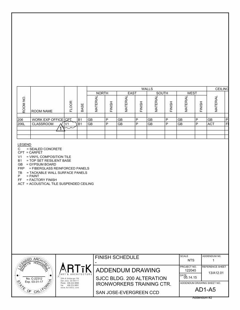
Item 8 Drawing A12.01, Detail 13 Finish Schedule A. Change flooring in 206L Classroom to Vinyl Composition Tile, see AD1-A5.
Item 9 Drawing A12.02 Details – Add Detail 20, see AD1-A6.
Item 10 Drawing A12.04 Interior Details – delete Details 5, 6, 8, 13 & 14.
Item 11 Add Details AD1-A6 and AD1-A7 addressing the duct penetration to the roof attached to
this addendum.
Mechanical:
Item 12 Drawing M2.1, Floor Plan A. New duct sizes provided for supply air out of existing furnace. B. Point of connection for new compressed air to existing CA located. C. Modify Sheet Note 1; add Sheet Note 11.
Item 13 Drawing M4.1, Schedules
A. Remove (REFERENCE ONLY) from the Exhaust Fan Schedule title. B. Modify Note 4 in the Split System Fan Coil Unit Schedule.
Item 14 Drawing M6.1, Details – Detail 1, Roof penetration portion of detail modified.
. Electrical:
Item 15 Drawing E2.0, Demolition Plan A. Revise Panel “A2” to be removed, not relocated. B. Revised Sheet Note 5.
Item 16 Drawing E2.2, Power & Signal Plan
A. Added ceiling power outlet and data outlet for window display. B. Panel “A2” to be new, not relocated.
Item 17 Drawing E2.3, Power Distribution Plan - Added notation for extension of existing
conduit unistrut support.
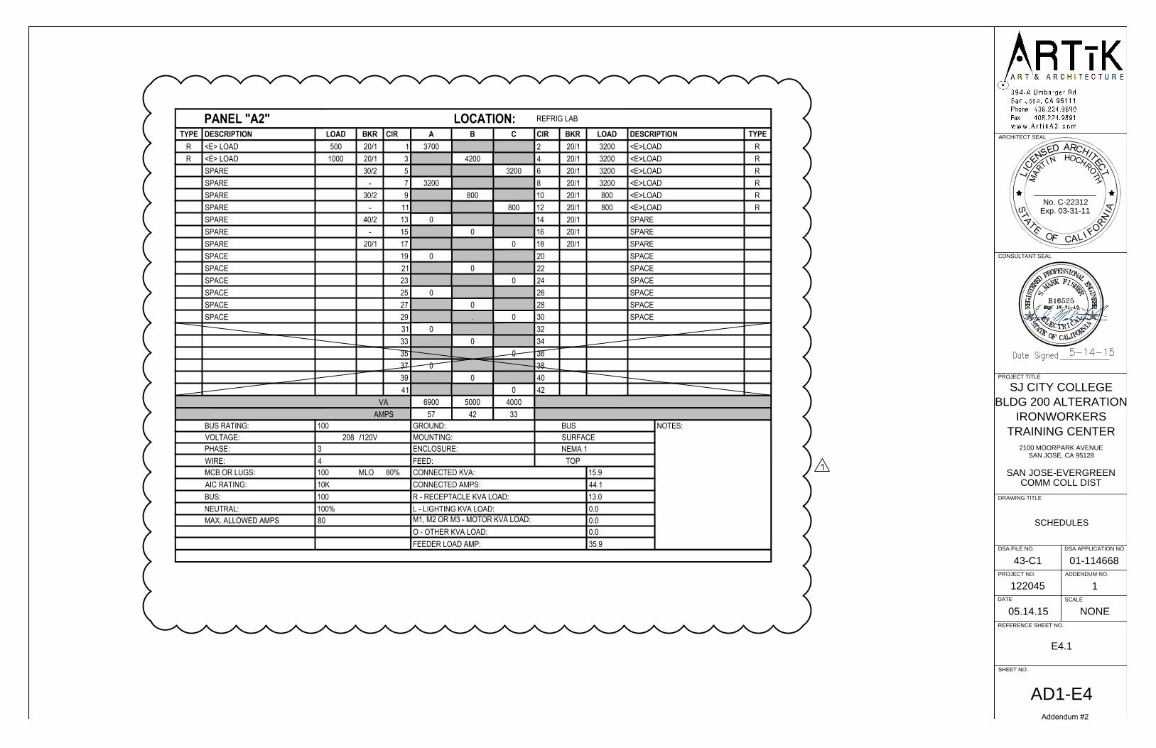
Item 18 Drawing E4.1 Schedules - Added “A2” panel schedule
RESPONSE TO CONTRACTOR QUESTIONS
Item 19 Pre-Bid RFI:
Question: Drawing M6.1, Detail 1 refers to architectural and structural drawings for roof penetration details. None are shown on architectural drawings.
Response: Detail M6.1 I snow deleted. Refer to Details AD1-A6 and AD1-A7 attached to this addendum.
Addendum #2

ARTIK ART AND ARCHITECTURE ADDENDUM #1 May 14, 2015
PAGE 3 OF 3
Item 20 Pre-Bid RFI:
Question: Drawing M2.1, Column Lines 13 and E make no reference to rectangular duct size and if it is new work.
Response: Drawing has been revised with duct sizing.
Item 21 Pre-Bid RFI:
Question: Reference Drawing M2.1 – Where is the location of existing compressed air pipe? Response: Drawing has been revised showing compressed air pipe location.
Item 22 Pre-Bid RFI:
Question: Drawing M4.1 exhaust fan schedule indicates “Reference Only”. Spec Section 23 34 16 and 23 34 22 calls to furnish and install exhaust fan. Please clarify.
Response: Notation “Reference Only” has been deleted. The Contractor will be required to furnish and install the exhaust fan and all other components and equipment for the Fume Extraction System as per Specification Sections 23 34 16 and 23 34 23.
Item 23 Pre-Bid RFI:
Question: On the schedule for the Split System Fan Coil Units, note 4 states “All controls will
be by the EMS contractor”. There is no specification for controls. We would need to know who the vendor is for this as well.
Response: This note is to be disregarded. The control of the system is integral to the specified components. The Contractor is to provide the control wiring between the condenser and fan coil unit.
Item 24 Pre-Bid RFI:
Question: On the Exhaust Fan schedule, it states for reference only. Is this fan existing? If so,
there is a filter bank that is by the same manufacturer as shown on sheet note 9/M2.1. Is the filter bank existing as well?
Response: Notation “Reference Only” has been deleted. The Contractor will be required to furnish and install the exhaust fan and all other components and equipment for the Fume Extraction System as per Specification Sections 23 34 16 and 23 34 23.
Attachments: Specification Section 07 60 00 Sheet Metal Flashing & Trim Specification Section 09 65 13 Resilient Base and Accessories Specification Section 09 65 19 Resilient Tile Flooring AD1-A1 through AD1-A7 AD1-M1 through AD1-M4 AD1-E1 through AD1-E4
END OF ADDENDUM #1
Addendum #2
ARTIK ART & ARCHITECTURE 07 62 00 SHEET METAL FLASHING AND TRIM
PAGE 1
SECTION 07 62 00 - SHEET METAL FLASHING AND TRIM
PART 1 - GENERAL
1.1 RELATED DOCUMENTS
A. Drawings and general provisions of the Contract, including General and Supplementary Conditions and Division 01 Specification Sections, apply to this Section.
1.2 SUMMARY
A. Section Includes:
1. Formed steep-slope roof sheet metal fabrications.
B. Related Requirements:
1. Section 06 10 53 "Miscellaneous Rough Carpentry" for wood nailers, curbs, and blocking.
1.3 COORDINATION
A. Coordinate sheet metal flashing and trim layout and seams with sizes and locations of penetrations to be flashed, and joints and seams in adjacent materials.
B. Coordinate sheet metal flashing and trim installation with adjoining roofing and wall materials, joints, and seams to provide leakproof, secure, and noncorrosive installation.
1.4 ACTION SUBMITTALS
A. Product Data: For each type of product.
1. Include construction details, material descriptions, dimensions of individual components and profiles, and finishes for each manufactured product and accessory.
B. Shop Drawings: For sheet metal flashing and trim.
1. Include plans, elevations, sections, and attachment details. 2. Detail fabrication and installation layouts, expansion-joint locations, and keyed details.
Distinguish between shop- and field-assembled work. 3. Include identification of material, thickness, weight, and finish for each item and location
in Project. 4. Include details for forming, including profiles, shapes, seams, and dimensions. 5. Include details for joining, supporting, and securing, including layout and spacing of
fasteners, cleats, clips, and other attachments. Include pattern of seams. 6. Include details of termination points and assemblies.
Addendum #2

ARTIK ART & ARCHITECTURE 07 62 00 SHEET METAL FLASHING AND TRIM
PAGE 2
7. Include details of roof-penetration flashing. 8. Include details of edge conditions, including eaves, ridges, valleys, rakes, crickets, and
counterflashings as applicable. 9. Include details of special conditions. 10. Include details of connections to adjoining work.
1.5 INFORMATIONAL SUBMITTALS
A. Qualification Data: For fabricator.
1.6 CLOSEOUT SUBMITTALS
A. Maintenance Data: For sheet metal flashing and trim, and its accessories, to include in maintenance manuals.
1.7 QUALITY ASSURANCE
A. Fabricator Qualifications: Employs skilled workers who custom fabricate sheet metal flashing and trim similar to that required for this Project and whose products have a record of successful in-service performance.
1.8 DELIVERY, STORAGE, AND HANDLING
A. Do not store sheet metal flashing and trim materials in contact with other materials that might cause staining, denting, or other surface damage. Store sheet metal flashing and trim materials away from uncured concrete and masonry.
B. Protect strippable protective covering on sheet metal flashing and trim from exposure to sunlight and high humidity, except to extent necessary for period of sheet metal flashing and trim installation.
PART 2 - PRODUCTS
2.1 PERFORMANCE REQUIREMENTS
A. General: Sheet metal flashing and trim assemblies shall withstand wind loads, structural movement, thermally induced movement, and exposure to weather without failure due to defective manufacture, fabrication, installation, or other defects in construction. Completed sheet metal flashing and trim shall not rattle, leak, or loosen, and shall remain watertight.
B. Sheet Metal Standard for Flashing and Trim: Comply with NRCA's "The NRCA Roofing Manual" and SMACNA's "Architectural Sheet Metal Manual" requirements for dimensions and profiles shown unless more stringent requirements are indicated.
C. Thermal Movements: Allow for thermal movements from ambient and surface temperature changes to prevent buckling, opening of joints, overstressing of components, failure of joint
Addendum #2

ARTIK ART & ARCHITECTURE 07 62 00 SHEET METAL FLASHING AND TRIM
PAGE 3
sealants, failure of connections, and other detrimental effects. Base calculations on surface temperatures of materials due to both solar heat gain and nighttime-sky heat loss.
1. Temperature Change: 120 deg F, ambient; 180 deg F, material surfaces.
2.2 SHEET METALS
A. General: Protect mechanical and other finishes on exposed surfaces from damage by applying strippable, temporary protective film before shipping.
B. Metallic-Coated Steel Sheet: Provide zinc-coated (galvanized) steel sheet according to ASTM A 653/A 653M, G90 coating designation.
1. Surface: Smooth, flat and mill phosphatized for field painting.
2.3 UNDERLAYMENT MATERIALS
A. Felt: ASTM D 226/D 226M, Type II (No. 30), asphalt-saturated organic felt; nonperforated.
B. Slip Sheet: Rosin-sized building paper, 3 lb/100 sq. ft. minimum.
2.4 MISCELLANEOUS MATERIALS
A. General: Provide materials and types of fasteners, solder, protective coatings, sealants, and other miscellaneous items as required for complete sheet metal flashing and trim installation and as recommended by manufacturer of primary sheet metal unless otherwise indicated.
B. Fasteners: Wood screws, annular threaded nails, self-tapping screws, self-locking rivets and bolts, and other suitable fasteners designed to withstand design loads and recommended by manufacturer of primary sheet metal.
1. General: Blind fasteners or self-drilling screws, gasketed, with hex-washer head.
a. Exposed Fasteners: Heads matching color of sheet metal using plastic caps or factory-applied coating. Provide metal-backed EPDM or PVC sealing washers under heads of exposed fasteners bearing on weather side of metal.
2. Fasteners for Zinc-Coated (Galvanized) Steel Sheet: Series 300 stainless steel or hot-dip galvanized steel according to ASTM A 153/A 153M or ASTM F 2329.
C. Solder:
1. For Zinc-Coated (Galvanized) Steel: ASTM B 32, Grade Sn50, 50 percent tin and 50 percent lead or Grade Sn60, 60 percent tin and 40 percent lead.
D. Sealant Tape: Pressure-sensitive, 100 percent solids, polyisobutylene compound sealant tape with release-paper backing. Provide permanently elastic, nonsag, nontoxic, nonstaining tape 1/2 inch wide and 1/8 inch thick.
Addendum #2

ARTIK ART & ARCHITECTURE 07 62 00 SHEET METAL FLASHING AND TRIM
PAGE 4
E. Elastomeric Sealant: ASTM C 920, elastomeric polyurethane polymer sealant; of type, grade, class, and use classifications required to seal joints in sheet metal flashing and trim and remain watertight.
2.5 FABRICATION, GENERAL
A. General: Custom fabricate sheet metal flashing and trim to comply with details shown and recommendations in cited sheet metal standard that apply to design, dimensions, geometry, metal thickness, and other characteristics of item required. Fabricate sheet metal flashing and trim in shop to greatest extent possible.
1. Fabricate sheet metal flashing and trim in thickness or weight needed to comply with performance requirements, but not less than that specified for each application and metal.
2. Obtain field measurements for accurate fit before shop fabrication. 3. Form sheet metal flashing and trim to fit substrates without excessive oil canning,
buckling, and tool marks; true to line, levels, and slopes; and with exposed edges folded back to form hems.
B. Fabrication Tolerances: Fabricate sheet metal flashing and trim that is capable of installation to a tolerance of 1/4 inch in 20 feet on slope and location lines indicated on Drawings and within 1/8-inch offset of adjoining faces and of alignment of matching profiles.
C. Expansion Provisions: Form metal for thermal expansion of exposed flashing and trim.
D. Sealant Joints: Where movable, nonexpansion-type joints are required, form metal to provide for proper installation of elastomeric sealant according to cited sheet metal standard.
E. Seams: Fabricate nonmoving seams with flat-lock seams. Tin edges to be seamed, form seams, and solder.
F. Do not use graphite pencils to mark metal surfaces.
2.6 STEEP-SLOPE ROOF SHEET METAL FABRICATIONS
A. Roof-Penetration Flashing: Fabricate from the following materials:
1. Galvanized Steel: 24 gauge thick.
PART 3 - EXECUTION
3.1 EXAMINATION
A. Examine substrates, areas, and conditions, with Installer present, for compliance with requirements for installation tolerances, substrate, and other conditions affecting performance of the Work.
1. Verify compliance with requirements for installation tolerances of substrates.
Addendum #2
ARTIK ART & ARCHITECTURE 07 62 00 SHEET METAL FLASHING AND TRIM
PAGE 5
2. Verify that substrate is sound, dry, smooth, clean, sloped for drainage, and securely anchored.
3. Verify that air- or water-resistant barriers have been installed over sheathing or backing substrate to prevent air infiltration or water penetration.
B. Proceed with installation only after unsatisfactory conditions have been corrected.
3.2 UNDERLAYMENT INSTALLATION
A. Felt Underlayment: Install felt underlayment, wrinkle free, using adhesive to minimize use of mechanical fasteners under sheet metal flashing and trim. Apply in shingle fashion to shed water, with lapped joints of not less than 2 inches.
B. Apply slip sheet, wrinkle free, over underlayment before installing sheet metal flashing and trim.
3.3 INSTALLATION, GENERAL
A. General: Anchor sheet metal flashing and trim and other components of the Work securely in place, with provisions for thermal and structural movement. Use fasteners, solder, protective coatings, separators, sealants, and other miscellaneous items as required to complete sheet metal flashing and trim system.
1. Install sheet metal flashing and trim true to line, levels, and slopes. Provide uniform, neat seams with minimum exposure of solder, welds, and sealant.
2. Install sheet metal flashing and trim to fit substrates and to result in watertight performance. Verify shapes and dimensions of surfaces to be covered before fabricating sheet metal.
3. Install exposed sheet metal flashing and trim with limited oil canning, and free of buckling and tool marks.
4. Torch cutting of sheet metal flashing and trim is not permitted. 5. Do not use graphite pencils to mark metal surfaces.
B. Metal Protection: Where dissimilar metals contact each other, or where metal contacts pressure-treated wood or other corrosive substrates, protect against galvanic action or corrosion by painting contact surfaces with bituminous coating or by other permanent separation as recommended by sheet metal manufacturer or cited sheet metal standard.
1. Underlayment: Where installing sheet metal flashing and trim directly on cementitious or wood substrates, install underlayment and cover with slip sheet.
C. Expansion Provisions: Provide for thermal expansion of exposed flashing and trim. Space movement joints at maximum of 10 feet with no joints within 24 inches of corner or intersection.
D. Fasteners: Use fastener sizes that penetrate wood blocking or sheathing not less than 1-1/4 inches for nails and not less than 3/4 inch for wood screws.
Addendum #2
ARTIK ART & ARCHITECTURE 07 62 00 SHEET METAL FLASHING AND TRIM
PAGE 6
E. Conceal fasteners and expansion provisions where possible in exposed work and locate to minimize possibility of leakage. Cover and seal fasteners and anchors as required for a tight installation.
F. Seal joints as required for watertight construction.
1. Use sealant-filled joints unless otherwise indicated. Embed hooked flanges of joint members not less than 1 inch into sealant. Form joints to completely conceal sealant. When ambient temperature at time of installation is between 40 and 70 deg F, set joint members for 50 percent movement each way. Adjust setting proportionately for installation at higher ambient temperatures. Do not install sealant-type joints at temperatures below 40 deg F.
G. Soldered Joints: Clean surfaces to be soldered, removing oils and foreign matter. Pre-tin edges of sheets with solder to width of 1-1/2 inches; however, reduce pre-tinning where pre-tinned surface would show in completed Work.
1. Do not use torches for soldering. 2. Heat surfaces to receive solder, and flow solder into joint. Fill joint completely.
Completely remove flux and spatter from exposed surfaces.
3.4 ROOF FLASHING INSTALLATION
A. General: Install sheet metal flashing and trim to comply with performance requirements and cited sheet metal standard. Provide concealed fasteners where possible, and set units true to line, levels, and slopes. Install work with laps, joints, and seams that are permanently watertight and weather resistant.
B. Roof-Penetration Flashing: Coordinate installation of roof-penetration flashing with installation of roofing and other items penetrating roof. Seal with elastomeric sealant and clamp flashing to pipes that penetrate roof.
3.5 MISCELLANEOUS FLASHING INSTALLATION
A. Equipment Support Flashing: Coordinate installation of equipment support flashing with installation of roofing and equipment. Weld or seal flashing with elastomeric sealant to equipment support member.
3.6 ERECTION TOLERANCES
A. Installation Tolerances: Shim and align sheet metal flashing and trim within installed tolerance of 1/4 inch in 20 feet on slope and location lines indicated on Drawings and within 1/8-inch offset of adjoining faces and of alignment of matching profiles.
3.7 CLEANING AND PROTECTION
A. Clean and neutralize flux materials. Clean off excess solder.
Addendum #2
ARTIK ART & ARCHITECTURE 07 62 00 SHEET METAL FLASHING AND TRIM
PAGE 7
B. Clean off excess sealants.
C. Remove temporary protective coverings and strippable films as sheet metal flashing and trim are installed unless otherwise indicated in manufacturer's written installation instructions. On completion of sheet metal flashing and trim installation, remove unused materials and clean finished surfaces as recommended by sheet metal flashing and trim manufacturer. Maintain sheet metal flashing and trim in clean condition during construction.
D. Replace sheet metal flashing and trim that have been damaged or that have deteriorated beyond successful repair by finish touchup or similar minor repair procedures.
END OF SECTION 07 62 00
Addendum #2

ARTIK ART & ARCHITECTURE 09 65 13 RESILIENT BASE AND ACCESSORIES
PAGE 1
SECTION 09 65 13 - RESILIENT BASE AND ACCESSORIES
PART 1 - GENERAL
1.1 RELATED DOCUMENTS
A. Drawings and general provisions of the Contract, including General and Supplementary Conditions and Division 01 Specification Sections, apply to this Section.
1.2 SUMMARY
A. Section Includes:
1. Resilient base. 2. Resilient molding accessories.
1.3 ACTION SUBMITTALS
A. Product Data: For each type of product.
B. Samples: For each exposed product and for each color and texture specified, not less than 12 inches long.
C. Samples for Verification: For each type of product indicated and for each color, texture, and pattern required in manufacturer's standard-size Samples, but not less than 12 inches long.
1.4 MAINTENANCE MATERIAL SUBMITTALS
A. Furnish extra materials that match products installed and that are packaged with protective covering for storage and identified with labels describing contents.
1. Furnish not less than 1 coil for every 500 linear feet or fraction thereof, of each type, color, pattern, and size of resilient product installed.
1.5 QUALITY ASSURANCE
A. Mockups: Build mockups to verify selections made under Sample submittals and to demonstrate aesthetic effects and set quality standards for materials and execution.
1. Coordinate mockups in this Section with mockups specified in other Sections.
Addendum #2

ARTIK ART & ARCHITECTURE 09 65 13 RESILIENT BASE AND ACCESSORIES
PAGE 2
1.6 DELIVERY, STORAGE, AND HANDLING
A. Store resilient products and installation materials in dry spaces protected from the weather, with ambient temperatures maintained within range recommended by manufacturer, but not less than 50 deg F or more than 90 deg F.
1.7 FIELD CONDITIONS
A. Maintain ambient temperatures within range recommended by manufacturer, but not less than 70 deg F or more than 95 deg F, in spaces to receive resilient products during the following time periods:
1. 48 hours before installation. 2. During installation. 3. 48 hours after installation.
B. After installation and until Substantial Completion, maintain ambient temperatures within range recommended by manufacturer, but not less than 55 deg F or more than 95 deg F.
C. Install resilient products after other finishing operations, including painting, have been completed.
PART 2 - PRODUCTS
2.1 VINYL BASE
A. Manufacturers: Subject to compliance with requirements, provide products by one of the following:
1. Armstrong World Industries, Inc. 2. Burke Mercer Flooring Products; a division of Burke Industries Inc. 3. Johnsonite; A Tarkett Company. 4. Or equal.
B. Product Standard: ASTM F 1861, Type TV (vinyl, thermoplastic).
1. Group: I (solid, homogeneous). 2. Style and Location:
a. Style A, Straight: Provide in areas with carpet. b. Style B, Cove: Provide in areas with resilient flooring.
C. Minimum Thickness: 0.125 inch.
D. Height: 6 inches.
E. Lengths: Coils in manufacturer's standard length.
F. Outside Corners: Job formed.
Addendum #2

ARTIK ART & ARCHITECTURE 09 65 13 RESILIENT BASE AND ACCESSORIES
PAGE 3
G. Inside Corners: Job formed.
H. Colors and Patterns: Black.
2.2 VINYL MOLDING ACCESSORY
A. Description: Vinyl nosing for carpet nosing and resilient flooring, reducer strip for resilient flooring, and carpet transition strips.
B. Locations: At material transitions.
C. Colors and Patterns: Black.
2.3 INSTALLATION MATERIALS
A. Trowelable Leveling and Patching Compounds: Latex-modified, portland cement based or blended hydraulic-cement-based formulation provided or approved by resilient-product manufacturer for applications indicated.
B. Adhesives: Water-resistant type recommended by resilient-product manufacturer for resilient products and substrate conditions indicated.
PART 3 - EXECUTION
3.1 EXAMINATION
A. Examine substrates, with Installer present, for compliance with requirements for maximum moisture content and other conditions affecting performance of the Work.
1. Verify that finishes of substrates comply with tolerances and other requirements specified in other Sections and that substrates are free of cracks, ridges, depressions, scale, and foreign deposits that might interfere with adhesion of resilient products.
B. Proceed with installation only after unsatisfactory conditions have been corrected.
1. Installation of resilient products indicates acceptance of surfaces and conditions.
3.2 PREPARATION
A. Prepare substrates according to manufacturer's written instructions to ensure adhesion of resilient products.
B. Fill cracks, holes, and depressions in substrates with trowelable leveling and patching compound; remove bumps and ridges to produce a uniform and smooth substrate.
C. Do not install resilient products until they are the same temperature as the space where they are to be installed.
Addendum #2

ARTIK ART & ARCHITECTURE 09 65 13 RESILIENT BASE AND ACCESSORIES
PAGE 4
1. At least 48 hours in advance of installation, move resilient products and installation materials into spaces where they will be installed.
D. Immediately before installation, sweep and vacuum clean substrates to be covered by resilient products.
3.3 RESILIENT BASE INSTALLATION
A. Comply with manufacturer's written instructions for installing resilient base.
B. Apply resilient base to walls, columns, pilasters, casework and cabinets in toe spaces, and other permanent fixtures in rooms and areas where base is required.
C. Install resilient base in lengths as long as practical without gaps at seams and with tops of adjacent pieces aligned.
D. Tightly adhere resilient base to substrate throughout length of each piece, with base in continuous contact with horizontal and vertical substrates.
E. Do not stretch resilient base during installation.
F. On masonry surfaces or other similar irregular substrates, fill voids along top edge of resilient base with manufacturer's recommended adhesive filler material.
G. Job-Formed Corners:
1. Outside Corners: Use straight pieces of maximum lengths possible and form with returns not less than 12 inches in length.
a. Form without producing discoloration (whitening) at bends.
2. Inside Corners: Use straight pieces of maximum lengths possible and form with returns not less than 12 inches in length.
a. Miter or cope corners to minimize open joints.
H. Do not use last 12 inches of coils without approval of Architect due to excessive curling.
3.4 RESILIENT ACCESSORY INSTALLATION
A. Comply with manufacturer's written instructions for installing resilient accessories.
B. Resilient Molding Accessories: Butt to adjacent materials and tightly adhere to substrates throughout length of each piece. Install reducer strips at edges of floor covering that would otherwise be exposed.
3.5 CLEANING AND PROTECTION
A. Comply with manufacturer's written instructions for cleaning and protecting resilient products.
Addendum #2

ARTIK ART & ARCHITECTURE 09 65 13 RESILIENT BASE AND ACCESSORIES
PAGE 5
B. Perform the following operations immediately after completing resilient-product installation:
1. Remove adhesive and other blemishes from exposed surfaces.
C. Protect resilient products from mars, marks, indentations, and other damage from construction operations and placement of equipment and fixtures during remainder of construction period.
D. Floor Polish: Remove soil, visible adhesive, and surface blemishes from resilient stair treads before applying liquid floor polish.
1. Apply six coat(s).
E. Cover resilient products subject to wear and foot traffic until Substantial Completion.
END OF SECTION 09 65 13
Addendum #2

ARTIK ART & ARCHITECTURE 09 65 19 RESILIENT TILE FLOORING
PAGE 1
SECTION 09 65 19 - RESILIENT TILE FLOORING
PART 1 - GENERAL
1.1 RELATED DOCUMENTS
A. Drawings and general provisions of the Contract, including General and Supplementary Conditions and Division 01 Specification Sections, apply to this Section.
1.2 SUMMARY
A. Section Includes:
1. Vinyl composition floor tile.
1.3 ACTION SUBMITTALS
A. Product Data: For each type of product.
B. Samples for Initial Selection: For each type of floor tile indicated.
1.4 INFORMATIONAL SUBMITTALS
A. Qualification Data: For Installer.
1.5 CLOSEOUT SUBMITTALS
A. Maintenance Data: For each type of floor tile to include in maintenance manuals.
1.6 MAINTENANCE MATERIAL SUBMITTALS
A. Furnish extra materials that match products installed and that are packaged with protective covering for storage and identified with labels describing contents.
1. Floor Tile: Furnish one box for every 50 boxes or fraction thereof, of each type, color, and pattern of floor tile installed.
1.7 QUALITY ASSURANCE
A. Installer Qualifications: A qualified installer who employs workers for this Project who are competent in techniques required by manufacturer for floor tile installation and seaming method indicated.
Addendum #2

ARTIK ART & ARCHITECTURE 09 65 19 RESILIENT TILE FLOORING
PAGE 2
B. Mockups: Build mockups to verify selections made under Sample submittals and to demonstrate aesthetic effects and set quality standards for materials and execution.
1. Build mockups for floor tile including resilient base and accessories.
a. Size: Minimum 100 sq. ft. for each type, color, and pattern in locations directed by Architect.
2. Approval of mockups does not constitute approval of deviations from the Contract Documents contained in mockups unless Architect specifically approves such deviations in writing.
3. Subject to compliance with requirements, approved mockups may become part of the completed Work if undisturbed at time of Substantial Completion.
1.8 DELIVERY, STORAGE, AND HANDLING
A. Store floor tile and installation materials in dry spaces protected from the weather, with ambient temperatures maintained within range recommended by manufacturer, but not less than 50 deg F or more than 90 deg F. Store floor tiles on flat surfaces.
1.9 FIELD CONDITIONS
A. Maintain ambient temperatures within range recommended by manufacturer, but not less than 70 deg F or more than 95 deg F, in spaces to receive floor tile during the following time periods:
1. 48 hours before installation. 2. During installation. 3. 48 hours after installation.
B. After installation and until Substantial Completion, maintain ambient temperatures within range recommended by manufacturer, but not less than 55 deg F or more than 95 deg F.
C. Close spaces to traffic during floor tile installation.
D. Close spaces to traffic for 48 hours after floor tile installation.
E. Install floor tile after other finishing operations, including painting, have been completed.
PART 2 - PRODUCTS
2.1 PERFORMANCE REQUIREMENTS
A. Fire-Test-Response Characteristics: For resilient tile flooring, as determined by testing identical products according to ASTM E 648 or NFPA 253 by a qualified testing agency.
1. Critical Radiant Flux Classification: Class I, not less than 0.45 W/sq. cm.
Addendum #2

ARTIK ART & ARCHITECTURE 09 65 19 RESILIENT TILE FLOORING
PAGE 3
2.2 VINYL COMPOSITION FLOOR TILE
A. Manufacturers: Subject to compliance with requirements, provide products by one of the following:
1. Armstrong World Industries, Inc. 2. Congoleum Corporation. 3. Or equal.
B. Tile Standard: ASTM F 1066, Class 1, solid-color tile.
C. Wearing Surface: Smooth.
D. Thickness: 0.125 inch.
E. Size: 12 by 12 inches.
F. Colors and Patterns: As selected by Architect from full range of industry colors.
1. Classroom: three colors in pattern to be provided by Architect.
2.3 INSTALLATION MATERIALS
A. Trowelable Leveling and Patching Compounds: Latex-modified, portland cement based or blended hydraulic-cement-based formulation provided or approved by floor tile manufacturer for applications indicated.
B. Adhesives: Water-resistant type recommended by floor tile and adhesive manufacturers to suit floor tile and substrate conditions indicated.
C. Floor Polish: Provide protective, liquid floor-polish products recommended by floor tile manufacturer.
PART 3 - EXECUTION
3.1 EXAMINATION
A. Examine substrates, with Installer present, for compliance with requirements for maximum moisture content and other conditions affecting performance of the Work.
1. Verify that finishes of substrates comply with tolerances and other requirements specified in other Sections and that substrates are free of cracks, ridges, depressions, scale, and foreign deposits that might interfere with adhesion of floor tile.
B. Proceed with installation only after unsatisfactory conditions have been corrected.
Addendum #2

ARTIK ART & ARCHITECTURE 09 65 19 RESILIENT TILE FLOORING
PAGE 4
3.2 PREPARATION
A. Prepare substrates according to floor tile manufacturer's written instructions to ensure adhesion of resilient products.
B. Concrete Substrates: Prepare according to ASTM F 710.
1. Verify that substrates are dry and free of curing compounds, sealers, and hardeners. 2. Remove substrate coatings and other substances that are incompatible with adhesives and
that contain soap, wax, oil, or silicone, using mechanical methods recommended by floor tile manufacturer. Do not use solvents.
3. Alkalinity and Adhesion Testing: Perform tests recommended by floor tile manufacturer. Proceed with installation only after substrate alkalinity falls within range on pH scale recommended by manufacturer in writing, but not less than 5 or more than 10 pH.
4. Moisture Testing: Proceed with installation only after substrates pass testing according to floor tile manufacturer's written recommendations, but not less stringent than the following:
a. Perform anhydrous calcium chloride test according to ASTM F 1869. Proceed with installation only after substrates have maximum moisture-vapor-emission rate of 3 lb of water/1000 sq. ft. in 24 hours.
b. Perform relative humidity test using in situ probes according to ASTM F 2170. Proceed with installation only after substrates have a maximum 75 percent relative humidity level.
C. Fill cracks, holes, and depressions in substrates with trowelable leveling and patching compound; remove bumps and ridges to produce a uniform and smooth substrate.
D. Do not install floor tiles until they are the same temperature as the space where they are to be installed.
1. At least 48 hours in advance of installation, move resilient floor tile and installation materials into spaces where they will be installed.
E. Immediately before installation, sweep and vacuum clean substrates to be covered by resilient floor tile.
3.3 FLOOR TILE INSTALLATION
A. Comply with manufacturer's written instructions for installing floor tile.
B. Lay out floor tiles from center marks established with principal walls, discounting minor offsets, so tiles at opposite edges of room are of equal width. Adjust as necessary to avoid using cut widths that equal less than one-half tile at perimeter.
1. Lay tiles square with room axis in pattern provide by Architect.
C. Match floor tiles for color and pattern by selecting tiles from cartons in the same sequence as manufactured and packaged, if so numbered. Discard broken, cracked, chipped, or deformed tiles.
Addendum #2

ARTIK ART & ARCHITECTURE 09 65 19 RESILIENT TILE FLOORING
PAGE 5
1. Lay tiles with grain direction alternating in adjacent tiles (basket-weave pattern) in pattern of colors provided by Architect.
D. Scribe, cut, and fit floor tiles to butt neatly and tightly to vertical surfaces and permanent fixtures including built-in furniture, cabinets, pipes, outlets, and door frames.
E. Extend floor tiles into toe spaces, door reveals, closets, and similar openings. Extend floor tiles to center of door openings.
F. Maintain reference markers, holes, and openings that are in place or marked for future cutting by repeating on floor tiles as marked on substrates. Use chalk or other nonpermanent marking device.
G. Adhere floor tiles to flooring substrates using a full spread of adhesive applied to substrate to produce a completed installation without open cracks, voids, raising and puckering at joints, telegraphing of adhesive spreader marks, and other surface imperfections.
3.4 CLEANING AND PROTECTION
A. Comply with manufacturer's written instructions for cleaning and protecting floor tile.
B. Perform the following operations immediately after completing floor tile installation:
1. Remove adhesive and other blemishes from exposed surfaces. 2. Sweep and vacuum surfaces thoroughly. 3. Damp-mop surfaces to remove marks and soil.
C. Protect floor tile from mars, marks, indentations, and other damage from construction operations and placement of equipment and fixtures during remainder of construction period.
D. Floor Polish: Remove soil, adhesive, and blemishes from floor tile surfaces before applying liquid floor polish.
1. Apply six coat(s).
E. Cover floor tile until Substantial Completion.
END OF SECTION 09 65 19
Addendum #2

A R T & A R C H I T E C T U R E
Addendum #2

A R T & A R C H I T E C T U R E
Addendum #2

A R T & A R C H I T E C T U R E
Addendum #2

A R T & A R C H I T E C T U R E
Addendum #2
A R T & A R C H I T E C T U R E
Addendum #2

A R T & A R C H I T E C T U R E
Addendum #2

A R T & A R C H I T E C T U R E
Addendum #2

E
D
E
D
207L
206
19,20/A8.01
WORK EXPERIENCE
OFFICE
207I
STORAGE
207E
OFFICE
207F
STORAGE
207J
CLASSROOM
206L.1
MECH
CARPET
12 13 14 15 16 17 1812 13 14 15 16 17 18
ASSEMBLY AREA
MECHANICAL PLANSHEET NO.
SJ CITY COLLEGE
SCALE
REFERENCE SHEET NO.
ADDENDUM NO.PROJECT NO.
43-C1
DATE
122045
SAN JOSE-EVERGREEN
SAN JOSE, CA 95128
2100 MOORPARK AVENUE
BLDG 200 ALTERATION
DRAWING TITLE
PROJECT TITLE
CONSULTANT SEAL
ARCHITECT SEAL
COMM COLL DIST
DSA APPLICATION NO.DSA FILE NO.
01-114668
IRONWORKERS
TRAINING CENTER
T
A
I
C
S
L
No. C-22312
Exp. 03-31-17
L
E
F
O
AC
T
F
I
N
R
O
I
A
C
E
E
N
S
D
RA
E
T
C
T
I
H
H
M
H
R
O
O
C
N
I
T
A
R
H
T
MECHANICAL PLAN
05.14.15
1
1/8"=1'-0"
M2.1
AD1-M1
Addendum #2

SHEET NO.
SJ CITY COLLEGE
SCALE
REFERENCE SHEET NO.
ADDENDUM NO.PROJECT NO.
43-C1
DATE
122045
SAN JOSE-EVERGREEN
SAN JOSE, CA 95128
2100 MOORPARK AVENUE
BLDG 200 ALTERATION
DRAWING TITLE
PROJECT TITLE
CONSULTANT SEAL
ARCHITECT SEAL
COMM COLL DIST
DSA APPLICATION NO.DSA FILE NO.
01-114668
IRONWORKERS
TRAINING CENTER
T
A
I
C
S
L
No. C-22312
Exp. 03-31-17
L
E
F
O
AC
T
F
I
N
R
O
I
A
C
E
E
N
S
D
RA
E
T
C
T
I
H
H
M
H
R
O
O
C
N
I
T
A
R
H
T
MECHANICAL PLAN
05.14.15
1
NA
M2.1
AD1-M2
Addendum #2

EXHAUST FAN SCHEDULE
CF:CEILING FAN IF:INLINE FAN
RE:ROOF EXHAUST UB:UP BLAST
MARK MFR MODEL
FAN
TYPE
CFM
FAN
SPEED
(RPM)
S.P. IN
"WG
ENCLOSURE
DRIVE
TYPE
ELECTRICAL OPERATING
WEIGHT
LBS.
MOUNTING
DETAIL
HP FLA VOLTS/ Ф
EF/1 LINCOLN ELECTRIC SQBI-300 13000 - 12.0 D 40 208/3 1700 -
NOTES:
1. PROVIDE WITH VFD (CONTROLLED BY SYSTEM PRESSURE) & VIBRATION ISOLATATORS.
SPLIT SYSTEM FAN COIL UNIT SCHEDULE
MARK SERVES MFR MODEL TONS
SUPPLY FAN ELECTRICAL DATA
OPR
WEIGHT
NOTES:
CFM MIN O.A. PHASE MCA MOCP
FC/1 OFFICE MITSUBISHIMSZ-GE18NA
1 1/2 340 60 208/1 1.0 0.76 301, 2, 3, 4, 5, 6
NOTES:
1. PROVIDE WITH FACTORY SUPPLIED CONDENSATE PUMP. CONDENSATE PUMP POWER SUPPLY TO BE TAPPED FROM INDOOR UNIT.
2. PROVIDE WITH WALL THERMOSTAT OPTION.
3. PROVIDE WITH R-410A REFRIGERANT
4. PROVIDE UNIT WITH THERMOSTAT CONTROL INTERFACE THAT WILL ALLOW MONITORING BY THE (E) EMS.
5. INDOOR UNIT RECEIVES POWER FROM OUTDOOR CONDENSING UNIT
NOTES
1UB
FC/2 CLASSROOM MITSUBISHI
FC/3 CLASSROOM MITSUBISHI
CONDENSING
UNIT
CU/1
CU/2
CU/3
FILTER TYPE
WASHABLE
WASHABLE
WASHABLE
HEATING
CAPACITY
MBH
21.6
COOLING
CAPACITY
TOT. MBH
17.2
MSZ-GE18NA1 1/2 340 75 21.617.2
MSZ-GE18NA1 1/2 340 75 21.617.2
208/1 1.0 0.76 30
208/1 1.0 0.76 30
6. REFER TO 4/M6.1 FOR MOUNTING DETAIL
1, 2, 3, 4, 5, 6
1, 2, 3, 4, 5, 6
- -
SHEET NO.
SJ CITY COLLEGE
SCALE
REFERENCE SHEET NO.
ADDENDUM NO.PROJECT NO.
43-C1
DATE
122045
SAN JOSE-EVERGREEN
SAN JOSE, CA 95128
2100 MOORPARK AVENUE
BLDG 200 ALTERATION
DRAWING TITLE
PROJECT TITLE
CONSULTANT SEAL
ARCHITECT SEAL
COMM COLL DIST
DSA APPLICATION NO.DSA FILE NO.
01-114668
IRONWORKERS
TRAINING CENTER
T
A
I
C
S
L
No. C-22312
Exp. 03-31-17
L
E
F
O
AC
T
F
I
N
R
O
I
A
C
E
E
N
S
D
RA
E
T
C
T
I
H
H
M
H
R
O
O
C
N
I
T
A
R
H
T
MECHANICAL SCHEDULES
05.14.15
1
NA
M4.1
AD1-M3
Addendum #2

SHEET NO.
SJ CITY COLLEGE
SCALE
REFERENCE SHEET NO.
ADDENDUM NO.PROJECT NO.
43-C1
DATE
122045
SAN JOSE-EVERGREEN
SAN JOSE, CA 95128
2100 MOORPARK AVENUE
BLDG 200 ALTERATION
DRAWING TITLE
PROJECT TITLE
CONSULTANT SEAL
ARCHITECT SEAL
COMM COLL DIST
DSA APPLICATION NO.DSA FILE NO.
01-114668
IRONWORKERS
TRAINING CENTER
T
A
I
C
S
L
No. C-22312
Exp. 03-31-17
L
E
F
O
AC
T
F
I
N
R
O
I
A
C
E
E
N
S
D
RA
E
T
C
T
I
H
H
M
H
R
O
O
C
N
I
T
A
R
H
T
MECHANICAL DETAILS
05.14.15
1
NTS
M6.1
AD1-M4
Addendum #2

STORAGE
OFFICE
207E
CLASSROOM
207J
STORAGE
207I
CLASSROOM
206L
WORK
EXPERIENCE
206
SHEET NO.
SJ CITY COLLEGE
SCALE
REFERENCE SHEET NO.
ADDENDUM NO.PROJECT NO.
43-C1
DATE
122045
SAN JOSE-EVERGREEN
SAN JOSE, CA 95128
2100 MOORPARK AVENUE
BLDG 200 ALTERATION
DRAWING TITLE
PROJECT TITLE
CONSULTANT SEAL
ARCHITECT SEAL
COMM COLL DIST
DSA APPLICATION NO.DSA FILE NO.
01-114668
IRONWORKERS
PLAN
DEMOLITION
05.14.15
1
AS SHOWN
E2.0
AD1-E1
TRAINING CENTER
No. C-22312
Exp. 03-31-11
DEMOLITION PLAN0 4' 16'8'
Addendum #2

STORAGE
OFFICE
207E
CLASSROOM
207J
STORAGE
207I
CLASSROOM
206L
WORK
EXPERIENCE
206
24" X 48"
CABINET
24" X 48"
CABINET
24" X 48"
CABINET
16' WHITEBOARD
LECTURN
PROJ SCREEN
16' WHITEBOARD
INSTRUCTOR'S
DESK
24 STUDENTS
SHEET NO.
SJ CITY COLLEGE
SCALE
REFERENCE SHEET NO.
ADDENDUM NO.PROJECT NO.
43-C1
DATE
122045
SAN JOSE-EVERGREEN
SAN JOSE, CA 95128
2100 MOORPARK AVENUE
BLDG 200 ALTERATION
DRAWING TITLE
PROJECT TITLE
CONSULTANT SEAL
ARCHITECT SEAL
COMM COLL DIST
DSA APPLICATION NO.DSA FILE NO.
01-114668
IRONWORKERS
PLAN
POWER & SIGNAL
05.14.15
1
AS SHOWN
E2.2
AD1-E2
TRAINING CENTER
No. C-22312
Exp. 03-31-11
POWER & SIGNAL PLAN0 4' 16'8'
Addendum #2

17 18 19 20 21 22 23 24 25
CLASSROOM
207J
CLASSROOM
207N
LAB
207C
STORAGE
207M
STORAGE
207G
STORAGE
208D
STORAGE
208E
CLASSROOM
208
TOILET
208F
OFFICE
208B
STORAGE
208A
KITCHEN
208C
A/C LAB
208L
A/C LAB
209N
CLASSROOM
209
CLOSET
209D
OFFICE
209O
CONTROL ROOM
209F
BOILER &
FACILITIES
MAINTENANCE
LAB
207L
EQUIPMENT YARD EQUIPMENT YARD
EQUIPMENT YARD
EQUIPMENT YARD
209G
STORAGE
209H
HALLWAY
WOMENS
209F
CONTROL ROOM
209C
IDF
209A
TOILET
209O
OFFICE
209D
CLOSET
209L
AIR
CONDITIONING -
LIVE EQUIP. -
REFRIG. LAB
2928272625
SHEET NO.
SJ CITY COLLEGE
SCALE
REFERENCE SHEET NO.
ADDENDUM NO.PROJECT NO.
43-C1
DATE
122045
SAN JOSE-EVERGREEN
SAN JOSE, CA 95128
2100 MOORPARK AVENUE
BLDG 200 ALTERATION
DRAWING TITLE
PROJECT TITLE
CONSULTANT SEAL
ARCHITECT SEAL
COMM COLL DIST
DSA APPLICATION NO.DSA FILE NO.
01-114668
IRONWORKERS
PLAN
DEMOLITION
POWER
05.14.15
1
AS SHOWN
E2.3
AD1-E3
TRAINING CENTER
No. C-22312
Exp. 03-31-11
POWER DISTRIBUTION PLAN0 32'8' 16'
Addendum #2
SHEET NO.
SJ CITY COLLEGE
SCALE
REFERENCE SHEET NO.
ADDENDUM NO.PROJECT NO.
43-C1
DATE
122045
SAN JOSE-EVERGREEN
SAN JOSE, CA 95128
2100 MOORPARK AVENUE
BLDG 200 ALTERATION
DRAWING TITLE
PROJECT TITLE
CONSULTANT SEAL
ARCHITECT SEAL
COMM COLL DIST
DSA APPLICATION NO.DSA FILE NO.
01-114668
IRONWORKERS
SCHEDULES
05.14.15
1
NONE
E4.1
AD1-E4
TRAINING CENTER
No. C-22312
Exp. 03-31-11
Addendum #2