tools.ru · argus argus 152 1 argus 152 manual version: 1.00/ en important notice: a basic argus...
TRANSCRIPT

ARGUS
ARGUS 152 Manual
Version: 1.00/ EN
Important Notice:A basic ARGUS package includes at least a DSL interface (ADSL or VDSL) together with various related functions and tests. Support for other interfaces and functions is optional (see the Options in the data sheet). Consequently, depending on the scope of the functions delivered, certain menu items may be hidden.
ARGUS 152 1

ARGUS
by intec Gesellschaft für Informationstechnik mbH
D-58507 Lüdenscheid, Germany, 2012
Alle Rechte, auch der Übersetzung, sind vorbehalten. All rights, including those to the translation, reserved. Kein Teil des Werkes darf in irgendeiner Form (Druck, Fotokopie, Mikrofilm oder einem anderen Verfahren) ohne schriftliche Genehmigung reproduziert, ver-vielfältigt oder verbreitet werden.
All rights are reserved. No portion of this document may be reproduced, duplicated or dis-tributed in any form (print, copies, microfilm or on any other media) without intec’s written permission.
2 ARGUS 152

ARGUS
1 Introduction .........................................................................................7
2 Safety Instructions ...........................................................................122.1 Notes on Safety and Transport - Battery Packs ............................14
3 General Technical Data ....................................................................16
4 Operating Instructions .....................................................................18
5 Menu Hierarchy .................................................................................27
6 The Physical Layer ...........................................................................30
7 Operation on an ADSL Access ........................................................317.1 Setting the ADSL Interface and Access Mode ...............................327.2 ADSL Settings ...................................................................................337.3 The ARGUS in the ATU-R Access Mode .........................................397.4 The ARGUS in the ATU-R Bridge Access Mode ............................577.5 The ARGUS in the ATU-R Router Access Mode ............................61
8 Operation on a VDSL Access ..........................................................648.1 Setting the VDSL Interface and Access Mode ...............................648.2 VDSL Settings ...................................................................................658.3 The ARGUS in the VTU-R Access Mode .........................................668.4 The ARGUS in the VTU-R Bridge Access Mode ............................748.5 The ARGUS in the VTU-R Router Access Mode ............................77
9 Operation on an Ethernet Access ...................................................809.1 Setting the Ethernet Interface ..........................................................819.2 Ethernet Settings ..............................................................................829.3 Setup an Ethernet connection .........................................................84
10 Virtual Lines (VL) ..............................................................................8610.1 Virtual Lines in the Status screen ...................................................8610.2 Virtual Line Profile (VL Profile) ........................................................8810.3 Virtual Line Activation ......................................................................90
10.3.1 Starting a service .....................................................................9010.3.2 Assigning additional Virtual Lines ............................................91
10.4 Virtual Line Settings .........................................................................9610.5 Display the Protocol Statistics ......................................................101
11 Services ...........................................................................................10611.1 Display the Service Statistics ........................................................107
12 Test Overview and Hotkey Assignment .......................................108
13 Loop .................................................................................................112
14 ATM Tests ........................................................................................11614.1 VPI/VCI Scan ...................................................................................11614.2 ATM-OAM Ping ................................................................................120
ARGUS 152 3

ARGUS
15 IP Tests ............................................................................................12415.1 IP Ping ..............................................................................................12415.2 Trace Route .....................................................................................13115.3 HTTP Download ..............................................................................13615.4 FTP Download .................................................................................14315.5 FTP Upload ......................................................................................14815.6 FTP Server .......................................................................................153
16 VoIP Tests .......................................................................................16016.1 Start VoIP Telephony ......................................................................16716.2 VoIP Wait .........................................................................................174
17 IPTV Tests .......................................................................................17717.1 IPTV ..................................................................................................177
17.1.1 Multiple Virtual Lines ..............................................................18117.2 IPTV Scan ........................................................................................19217.3 IPTV Passive ...................................................................................19917.4 Video on Demand (VoD) .................................................................203
18 Operation on an ISDN Access .......................................................21118.1 Setting the ISDN Interface and Access Mode ..............................21118.2 Initialization phase followed by a B channel Test .......................21318.3 ISDN Settings ..................................................................................21518.4 Bit Error Rate Test ..........................................................................21918.5 Supplementary Services Test ........................................................22918.6 Service check ..................................................................................23318.7 X.31 Test ..........................................................................................23518.8 Call Forwarding (CF) ......................................................................24018.9 Automatic Performance of Multiple Tests ....................................24418.10 Connection ......................................................................................24818.11 Time Measurement .........................................................................25718.12 Managing Multiple Tests on an ISDN Access ..............................26018.13 The L1 State of an S-Bus Access ..................................................26518.14 Leased Lines on an ISDN Access .................................................26618.15 Level Measuring on an ISDN Access ............................................272
19 Operation on a POTS access .........................................................27519.1 Setting the POTS Interface ............................................................27519.2 POTS Settings .................................................................................27819.3 Connection on a POTS Access .....................................................28219.4 POTS Monitor ..................................................................................28319.5 Level Measuring on a POTS Access .............................................284
4 ARGUS 152

ARGUS
20 Copper Tests ...................................................................................28520.1 R Measurement ...............................................................................28520.2 RC Measurement ............................................................................28720.3 Line Scope .......................................................................................289
20.3.1 Start Line Scope ....................................................................28920.3.2 Graphic functions ...................................................................292
20.4 Active Probe ....................................................................................29720.4.1 Active Probe II .......................................................................29720.4.2 Connect the Active Probe II ...................................................29820.4.3 Start Active Probe II (Line Scope as an example) .................298
20.5 TDR / Advanced TDR ......................................................................30120.5.1 TDR Settings .........................................................................30120.5.2 Start TDR ...............................................................................30320.5.3 Graphic functions ...................................................................30520.5.4 Examples ...............................................................................309
20.6 Line Qualification ............................................................................31320.6.1 LQ settings .............................................................................31420.6.2 Starting Line qualification .......................................................317
21 Test Results ....................................................................................32521.1 Saving Test results .........................................................................32621.2 Displaying the Saved Test Results ...............................................32721.3 Test Results – Sending to a PC .....................................................32721.4 Test Results – Deleting ..................................................................32821.5 Send All Test Results to a PC ........................................................32821.6 Delete All Test Results ...................................................................329
22 ARGUS Settings ..............................................................................33022.1 Trace/remote ...................................................................................33022.2 Device Settings ...............................................................................33122.3 Settings – Backup / Restore ........................................................33322.4 Reset Settings to Factory Settings ...............................................33522.5 Saving Call Numbers in the Speed-dialling Memory ...................336
23 Using the Battery Pack ...................................................................337
24 Firmware Update .............................................................................339
ARGUS 152 5

ARGUS
25 Appendix .........................................................................................341A) Acronyms .........................................................................................341B) Vendor identification numbers .........................................................349C) CAUSE-Messages – DSS1 Protocol ...............................................350D) ARGUS Error Messages (DSS1) .....................................................352E) Error message: PPP connection ......................................................354F) Error message: Download test ........................................................355G) HTTP status codes: .........................................................................356H) General Error Messages ..................................................................358I) VoIP SIP status codes .....................................................................359J) Software Licenses ...........................................................................362K) Index ................................................................................................363
6 ARGUS 152

1 Introduction
1 Introduction
The VDSL+ADSL universal test setCompact, lightweight and robust: The ARGUS 152 multifunction tester checks interfaces
and services quickly and reliably - and at a very reasonable price! VDSL2, ADSL, Ethernet,
ISDN (BRI S/T/U) and POTS, as well as the physical condition of the local loop, can be
easily tested without having to swap modules.
GigaBit Ethernet Interface and testsA new high-quality ADSL/VDSL chipset with improved efficiency ensures that the ARGUS
152 delivers high-performance testing and rapid analysis. In addition to resistance,
capacitance and voltage measurement, the ARGUS 152 features, when using its Gigabit
Ethernet interface, an optional HTTP download, which enables speeds at more than 200
Mbit/s on the protocol level. The ARGUS 152's optional Ethernet cabling tests make it
possible to detect shorts, opens or mismatches, but also the delay or polarity of the wire
pairs, among other things.
Physical analysis of the local loopOn request, the universal tester can also be extended on an individual basis, thus offering
the user a high degree of flexibility. For instance, additional copper tests (Cu tests) can be
used to assess line quality, even without synchronization with the DSLAM. If necessary,
these tests can also be considerably extended in the field by simply connecting the new
compact ARGUS Copper Box via USB, thus enabling all important elec-trical parameters
such as voltage, current, isolation resistance, symmetry (at 1 MHz), and many more, to be
automatically and quickly determined via tip, ring and ground. The optional Active Probe II
can even be used to carry out high-impedance measurements on an existing DSL
connection, without creating interference on it.
To quickly identify any asymmetries between the wires, if required, a symmetry test
compares the balance over the whole DSL frequency spectrum (up to 30 MHz) between
the tip wire and the ring wire with reference to ground. In the event of damage, the
integrated TDR (Time Domain Reflectometer) function can be used to measure line lengths
and trace sources of faults, such as bridged taps. Moreover, if required, an Advanced TDR
function (Adv. TDR) can be integrated, with which line lengths and sources of faults can be
detected even more accurately.
If lines without a DSL receiver (e.g. in the case of a rewiring) need to be tested for their DSL
suitability, the ARGUS 152 can optionally check this without any problem, even if there is
no DSLAM. Regardless of line condition and length, the user can use two devices and an
activated Line Qualification (LQ) function to determine data rates, even when systems
consisting of a modem (xTU-R) and DSLAM (xTU-C) fail.
ARGUS 152 7

1 Introduction
Triple Play and Quality of Service (QoS)Easy Triple Play testing: The handheld tester also offers an optional Triple Play analysis for
testing VoIP, IPTV and data services over xDSL and Ethernet. Thanks to its handset, the
ARGUS 152 can simulate not only terminal equipment such as a telephone, PC or STB, but
can also determine all relevant quality parameters. In this way, for example, voice quality
can be evaluated according to the MOS method. Several of these IP tests can also
optionally be performed using the new, more powerful IPv6 protocol.
Easy OperationThe large 320 x 240 pixel colour display and an intuitive menu structure, among other
things, guarantee user-friendly operation. A high-performance Li-Ion battery pack ensures
long operating times in the field.Software updates can be downloaded to a PC free of charge and then loaded into the
ARGUS at any time. They are available at http://www.argus.info/en/service/downloads/.
Note:Details on the use of the ARGUS Copper Box can be found in the related
separate manual.You should find these manual in the package with the delivered equipment. In
addition, you can always download the latest manuals from our website at http://www.argus.info/en/service/downloads/ or request them from our service
department.
8 ARGUS 152

1 Introduction
An overview of a few of the important ARGUS functions:
xDSL tests (ADSL, ADSL2 and ADSL2+, VDSL2)
- Synchronisation with the DSLAM (xTU-C) and determination of all relevant connection parameters and error counters
- Bridge, Router and Terminal Modes
Ethernet interface
- Gigabit Ethernet test interface (10/100/1000 Base-T), RJ-45
- Ethernet interface for remote functions (10/100 Base-T)
IP and ATM tests via xDSL and Ethernet
- ATM tests (ADSL only)
- ATM OAM ping, ATM OAM cell loop and VPI/VCI scan
- IP tests
- Ping and trace route tests (BRAS information, PPP trace and VLAN)
- Download tests to determine throughput (HTTP download, and FTP upload and
download)
- FTP server test, upload and download from ARGUS to ARGUS
- VoIP test
- VoIP terminal simulation, including acoustics (various codecs)
- OK/FAIL evaluations and display of the quality parameter
- Evaluation of the VoIP voice quality (QoS) in accordance with:- MOSCQE (ITU-T P.800), E-Model (ITU-T G.107)
- IPTV tests
- Stream requests (STB mode), IPTV channel scan, IPTV passive
- OK/FAIL evaluations and display of the quality parameter
- IPTV online trace for long-term analysis using WINanalyse
ISDN functions
- U-interface (4B3T or 2B1Q) in accordance with ANSI T1.601
- BRI interface in accordance with ITU-T I.430 in TE operation
- Tests of BRI leased lines (permanent circuits)
- Automatic service checks and supplementary service tests, etc.
- Evaluation of the ISDN speech quality directly at the BRI or U-interface
ARGUS 152 9

1 Introduction
POTS functions
- A full-fledged integrated analog handset (POTS)
- With DTMF and CLIP display, as well as pulse dialling
- High-impedance 2-wire monitor with voltage measurement
- Evaluation of speech quality directly on the POTS access
Copper Test functions (Copper Tests)
- R measurement: The ARGUS performs an ongoing resistance measurement and displays the results in real-time.
- RC measurements: Measurement of the loop resistance and the capacitance of the open (voltage-free) line (including a calculation of the line length).
- Line Scope: High-performance real-time line monitor with an x-axis display of time or frequency bands (fast Fourier transform (FFT)) up to 30 MHz.
- TDR: Time domain reflectometry function for measuring line length and locating faults in lines.
- Line qualification: Checking of the local loop for its suitability for DSL, including aDSL data rate estimation.
- Copper Box: The copper test functions of ARGUS can be extended by connecting ARGUS Copper box via the USB host interface. For more details see ARGUS Copper Box manual and datasheet.
Access acceptance report
When the ARGUS is connected to a PC via USB, it is, as an example, possible - with the
aid of the WINplus or WINanalyse software - to create a comprehensive test report on the
PC and print it.
10 ARGUS 152

1 Introduction
The Concept of the ARGUS Firmware User InterfaceThe ARGUS firmware presents - on a graphic Status screen - the results of tests made with
the latest in measurement technology. In this manner, all of the important processes can be
shown on a single screen together with main sequences with all the convenience and
transparence to which ARGUS users are accustomed.
In this manner - with its intuitive menu structure - the ARGUS makes it easy to not only configure, start and perform tests but also to examine the test results:
You will find other important information about profile structures on our website.
Should you have any further questions, please contact us:
intec Gesellschaft für Informationstechnik mbHRahmedestr. 90
D-58507 LüdenscheidTel.: +49 (0) 2351 / 9070-0
Fax: +49 (0) 2351 / 9070-70www.argus.info/en
- The physical layer - Layer 1 (e.g. DSL) - can be started and stopped completely independently of the higher layers such as Virtual Lines (L2/3), services or tests.
- Layer 2 (VLAN, VPI/VCI) and Layer 3 parameters (PPP, IP) are combined in independent Virtual Line profiles (VL profiles). Multiple VL profiles can be configured and started on a single DSL access. It is also possible to bridge and route multiple Virtual Lines concurrently.
- Thanks to the introduction of services between the Virtual Lines (VLs) and the Data, VoIP and IPTV tests, it is now possible to take an incoming call even when the ARGUS is used as an IP phone with VoIP activated.
ARGUS 152 11

2 Safety Instructions
2 Safety Instructions
The ARGUS may only be used with the included accessories. Usage of other accessories
may lead to erroneous measurements and may even cause damage to the ARGUS and the
connected installation. The ARGUS is only to be used in accordance with the instructions in
this documentation. Any other usage may result in bodily injury and destruction of the
ARGUS.
- Before connecting the ARGUS to an access make certain that the voltages on
the access are not high enough to be dangerous or outside the specified
range of the ARGUS or its accessories. You must also taken into account the
fact that the voltage may vary while the ARGUS is connected to the access.
- Regardless of the interface or access, use the ARGUS only for its intended
purpose.
- Voltages in excess of 50 V AC or 120 V DC can cause mortal injury.
- Never attempt a measurement when the battery pack (accumulator) is not
installed!
- The ARGUS is not watertight. Protect the ARGUS from exposure to water!
- Before replacing the battery pack, disconnect all the test leads and switch the
ARGUS off.CAUTION: Never remove the battery pack during operation.
- Unplug the power supply from the mains, once the ARGUS is switched off
and will no longer be used (for example after recharging the accumulators)!
- The ARGUS may only be used by trained personnel.
- Do not operate the ARGUS on a power supply that has other specifications. The specifications are: (Input: 100 V to 240 V AC; 50/60 Hz 0.45 A) (Output: 12 V DC; 1.5 A)
- Do not plug anything into the headset jack other than headsets approved by
the manufacturer; the use of this jack for any other application (e.g.
connection of a stereo system) is expressly prohibited.
- Do not plug anything into the USB Host interface (USB-A) except an Active
Probe II or a Copper Box or mobile storage media that does not use an
external power supply and is approved by the manufacturer. The use of this
jack for any other application (e.g. to connect to a PC) is expressly prohibited.
- The ARGUS Power jack must always be covered with the included rubber
cap (labeled "Power") while operating in battery mode.
- The electromagnetic compatibility of the ARGUS was checked in accordance
with the regulations stated in our Declaration of Conformity.This is a Class A device. It may cause radio interference in a living area. In
this event, the operator may be requested to take appropriate measures.
12 ARGUS 152

2 Safety Instructions
Return and Environmentally Acceptable Disposal
The RoHS (EU Directive on the “Restriction of Hazardous Substances”) guidelines, which
restrict the use of certain hazardous substances in electrical and electronic equipment,
apply in eight of the ten categories of the WEEE (EU Directive on “Waste Electrical and
Electronic Equipment”) guidelines. Devices which are in Category 9 “Monitoring and
Control Instruments” are currently excluded from the scope of the Directive. The ARGUS
products fall into Category 9 and are thus not subject to the RoHS guidelines. Nonetheless,
we have voluntarily complied with all of the RoHS guidelines since 1 January 2007.In compliance with WEEE (EU Directive on Waste of Electrical and Electronic Equipment)
2002/96/EU and the German Electrical and Electronic Equipment Act (ElektroG - Elektro-
und Elektronikgerätegesetz), we began marking our testers in October 2005 with the
following symbol:
( ) (DIN EN 50419).
In other words, the ARGUS and its accessories may not be disposed of in the household
waste. Regarding the return of old equipment, please contact our Service department.
- The ARGUS battery pack may only be actively charged (Charge battery) or
trickle charged (default setting: on) when the ambient temperature is between
0 °C (32 °F) and +40 °C (104 °F).
- If the ARGUS is operated under extreme conditions, it may have to
automatically shutdown, terminate the current test and drop the connection in
order to protect itself and the user. To ensure reliable long-term operation of the ARGUS, make certain that it is
protected from excessive temperatures.
- Do not open the tester.
- In connection with the lithium ion battery pack, please observe the following
notes regarding safety and transport.
- Before running a test or synchronizing on an interface, determine how the
ARGUS should be powered.
ARGUS 152 13

2 Safety Instructions
2.1 Notes on Safety and Transport - Battery Packs
Transport
The battery pack has been tested in accordance with the UN recommendations (ST/SG/AC.10/11/Rev. 4, Part III, Subsection 38.3). Protective measures have been implemented to prevent harm if it is exposed to excessive pressure, short-circuits, dangerous reverse currents or other destructive influences. However, since the amount of lithium contained in the battery pack is in any case less than the current threshold amount, neither the battery pack itself nor the ARGUS in which it is installed are subject to the international hazardous goods regulations. Nonetheless, these regulations may apply if several battery packs are transported at the same time.For more information, please contact us.
The protective features of the battery pack may be harmed if the following instructions are not observed. In this case extremely high currents and voltages may result, which could lead to abnormal chemical reactions, leaking acid, overheating, smoke, or an explosion and/or fire. Furthermore, if the user does not observe and comply with these instructions both the performance and service life may suffer.
Safety Instructions and Warnings
1. Do not disassemble or short-circuit the battery pack.
2. Do not throw the battery pack into a fire or heat it (> 60 °C) (140 °F).
3. Keep the battery pack dry - do not let it get wet or damp.
4. The ARGUS battery pack may only be actively charged (Charge accus) or trickle
charged (default setting: off) when the ambient temperature is between 0 °C (32 °F) and +40 °C (104 °F). To maximize a battery pack service life, if it is to be stored over a longer period of
time, it should not be exposed to temperatures in excess of +50 °C (122 °F).
5. The battery pack may only be charged using the associated ARGUS or a charger
approved by intec.
6. Do not damage the battery pack with a sharp object.
7. Do not throw the battery pack or expose it to shocks or impacts.
8. If a battery pack is damaged or deformed, do not use it.
9. Like any battery, the battery pack has two poles (plus and minus). To prevent
damage, make certain that it is correctly connected (polarity) to the ARGUS or
charger.
10. The battery pack may only be connected to the associated ARGUS or charger in
the intended manner.
11. The battery pack may not be directly connected to the output of a plug-in power
supply, an automobile cigarette lighter or similar power source.
12. The battery pack may only be used together with an ARGUS.
13. The battery pack may not be connected to, or stored or transported with metallic
objects.
14 ARGUS 152

2 Safety Instructions
14. Do not expose the battery pack to high electrostatic forces.
15. The battery pack may not be used in combination with primary (non-
rechargeable) batteries, nor may it be charged or discharged together with other
rechargeable batteries.
16. If the battery pack is still not properly charged when the charging time has
elapsed, do not charge it again.
17. Do not expose the battery pack to excessive pressure.
18. If the battery pack emits an odor or heats up, becomes discolored or misshapen,
or if there are any other indications of that it has malfunctioned while in use or
being charged or stored, remove the battery pack from the ARGUS or charger
immediately and do not use it again.
19. If the battery pack leaks acid, make certain that you do not get this acid in your
eyes or on your skin. In event that you get this acid in your eyes or on your skin,
rinse the affected area immediately with clean water. Do not rub the affected area.
In either case, immediate medical care is required. Otherwise, permanent injury
may result.
20. The battery pack must be kept out of reach of children.
21. Please read this manual and the associated safety instructions before using the
battery pack.
22. If you find that the battery pack emits an odor, is rusty or appears to be in anything
other than perfect condition before you first use it, please contact intec to
determine how to proceed.
ARGUS 152 15

3 General Technical Data
1
-
3 General Technical Data
ARGUS user safety tested in accordance with EN60950-
RoHS conformity pursuant to the WEEE guidelinesThe electromagnetic compatibility of the ARGUS was checked in accordance with the regulations stated in ourDeclaration of Conformity.
CE symbol The ARGUS 152 conforms with the EU Directive 2004/108/EC as well as 2009/C197/03. We would be happy tosupply you with a copy of the detailled Declaration of Conformity upon request.
Tester specifications:
Dimensions / Weight Inputs / Outputs
Height: 235 mm (9.25 in)Width: 97 mm (3.8 in)Depth: 65 mm (2.56 in)Weight: approx. 810 g (1.79 lbs)(including battery pack)
- RJ-45 (S0/BRI) for BRI- RJ-45 (Line) for xDSL, POTS, U-interface and
Copper Tests- Ethernet 10/100/1000 Base-T- Ethernet 10/100 Base-T- USB-A jack, USB Host interface- USB-B jack, USB Client interface- Jack for headset
Keypad
25 Keys
LCD display Temperature ranges
LCD color display with
switchable background lighting,320 x 240 pixels
Temperature range - charging batteries: 0 °C (+32 °F) to +40 °C (+104 °F)Operating temperature (in battery mode):-10 °C (+14 °F) to +50 °C (+122 °F)Operating temperature (with power supply/car adapter):
0 °C (+32 °F) to +40 °C (+104 °F)Storage temperature: -20 °C (-4 °F) to +60 °C (+140 °F)Humidity: up to 95 % relative humidity, non-condensing
Power supply
Lithium ion battery pack, rated voltage 7.2 V(observe and comply with the safety instructions)or 12 V / 1.5 mA ARGUS electronic plug-in power supply
Other information
16 ARGUS 152

3 General Technical Data
%2 %
Supported Standards:
ADSL (Line):ITU-T G.992.1, Annex A (ADSL)ITU-T G.992.2, Annex A (G.lite)ITU-T G.992.3, Annex A (ADSL2)ITU-T G.992.5, Annex A (ADSL2+)ITU-T G.992.1, Annex B (ADSL)ITU-T G.992.3, Annex B (ADSL2)ITU-T G.992.5, Annex B (ADSL2+)ITU-T G.992.3, Annex J (ADSL2)ITU-T G.992.5, Annex J (ADSL2+)ITU-T G.992.3, Annex L (RE-ADSL2 over POTS)ITU-T G.992.3, Annex L (RE-Narrow PSD ADSL2 over POTS)ITU-T G.992.3, Annex M (ADSL2)ITU-T G.992.5, Annex M (ADSL2+)ANSI T1.413ETSI TS 101 388 Annex C
ISDN BRI (S0/BRI):ITU-T I.430ITU-T G.821ITU-T X.31
ISDN U-interface (Line):ANSI T1.601
VDSL (Line):ITU-T G.993.2 (VDSL2)Profile:8a, 8b, 8c, 8d, 12a, 12b, 17a, 30aITU-T G.998.4 (G.INP, Retransmission)
R measurement / RC measurement (Line):Resistance measurement:- Precision for the range from 20 - 100 ±10 - Precision for the range from >100 - 100 k ±Capacitance measurement:- Precision for 1 nf - 1 µF: ±5 %
Ethernet (LAN):IEEE 802.3 - 10 Base-T - 100 Base-T- 1000 Base-TAutonegotiationAuto-MDI(X)
Dielectric strength:
Line:DC voltage: +200 V max.Alternating Current (AC): 100 Vpp max.
(Copper Tests only)DC voltage: +200 V max. (xDSL)DC voltage: +130 V max. (for POTS)DC voltage: +145 V max. (for U-interface)
S0/BRIDC voltage: +48 V max.
DC voltage measurement:- Precision: ±2 %
ARGUS 152 17

4 Operating Instructions
4 Operating Instructions
LEDs
Softkeys
Cursor keys
Confirmation key
Level key
Telephony: Pickup / Hang up
Power
MicrophoneFastener for shoulder strap
Numerical keypad
LC display
Return key
Shift key
Speaker
Power key
----
Switch the ARGUS onTo start up again after a "power down" (adjustable see page 331)To switch on the display backlighting (can also be done by pressing any
other key). In battery mode to save power, the backlighting will switch off
automatically after an adjustable period of time - see page 332.To switch off the ARGUS (must be pressed somewhat longer)After being idle for an adjustable period of time (for example after 10
minutes), the ARGUS will shutdown automatically if it is running in
battery mode (see page 337). If the ARGUS is connected to its power
supply, it will automatically charge its accumulators when it is switched
off (see page 337 Using the Battery Pack).
Confirmation key
----
Open menuOpen the next displayStart testConfirm the entry
18 ARGUS 152

4 Operating Instructions
Return key
---
The ARGUS will return to the previous display and ignore any entries
made at this level, e.g. changes to the settings Cancel testClose the graphic display
Cursor keys
-------
Scroll through the display line-by-line (vertical cursor keys)Move the cursor within a displayed line (horizontal cursor keys)When viewing a selection list or statistics, the cursor will jump to the
end of the list/statistics if the right cursor key is pressed or to the
beginning if the left cursor key is pressedSelect a menu, function or a testSetting the measurement range in a Copper TestMove the cursor in a graphic displaySelect functions in the graphic Status screen
Telephony
ISDN or POTS
--
Accept or hang upSimplified overlap sending: press the telephone key twice (ISDN only)
xDSL (access mode xTU-R, xTU-R Router) and Ethernet
- Start VoIP telephony
Level key
-
----
BRI or U-interface access: Start the Layer 1 measurement (level/voltage)xDSL access: Display the resultsEthernet: Open the resultsStart/Stop function in a real-time analysis (Line Scope / TDR)Open the graphic Status screen
Numerical keypad
--
Entry of the digits 0 to 9, letters and special charactersDirect access to functions appropriate for the selected Access (Hotkey),
e.g. page 110 et seq.
ARGUS 152 19

4 Operating Instructions
The ARGUS is in largest part operated with the 4 cursor keys, the confirmation key ,
the return key , the level key , and the three softkeys.
The current assignment of the three softkeys is shown in the lower line of the display.
On the following pages, only the softkey's meaning in the respective context is shown -
enclosed in angle brackets < >, e.g. <Menu>. The < > softkey serves the same function
as the confirmation key , the <> softkey performs the same function as the cursor
key on the ARGUS keypad, and so on.
Softkeys
-
-
The function of the 3 softkeys varies with the situation. The current
assignment of each is displayed on the bottom line of the display in
three blue blocks with white text, e.g.:<Menu>: The Main Menu will open
<Start>: Setup a connection or start a test
You will find the other softkeys described at the relevant points in the
manual.
Shift key
In some menus, a green circle with a green “S” will be shown in the
uppermost line in the display. This indicates that the softkeys are
assigned twice. In such a case, press the Shift key to change the
function of the softkey (for an example, see page 182).
Example
Press the Shift key: the function of the softkey will change accordingly.
20 ARGUS 152

4 Operating Instructions
Example of operation:
Current assignment of the softkeys
Press <No>: The displayed access will
not be used. The Access Menu will open.
Using
the
Select a line in the display:in this example, select a type of
access; the selected type will
marked in blue(in this example: ADSL).
Using
the
Confirm the selection: in this example, the ARGUS will
set the type of access to the one
marked in blue. The Access Menu
will open.
Using
the
Return to the previous display
without changing to marked type of
access.
Header: Shows the name of the menu (in this
example, the Access Menu), the name of the
currently running test etc.
Continuation on
next page
ARGUS 152 21

4 Operating Instructions
<Profile> Displays the profile, see page 34
<Menu> Open the Main Menu
<Start> Start the ADSL connection
<Edit> Open the xDSL and Ethernet settings
<Profile> Configure profile
<Start> Start the ADSL connection
22 ARGUS 152

4 Operating Instructions
Access up
Access down
PWR
Connection for the external plug-in power supply.If the plug-in power supply is connected, the
ARGUS will automatically disconnect the
accumulators (battery pack). After it is switched off,
the ARGUS will automatically recharge the
accumulators (see page 337).
ETH
Second LAN interface (VNC server)
USB-A
USB Host interface (Active Probe II, Copper Box)
USB-B (mini-USB):
USB Client interface (PC connection)
Jack for a headset
Yellow “Link/Data” LED:signals that a physical connection has
been established to another Ethernet
port
- LED on constantly: A connection has been setup.
- LED flashing: Active - sending or receiving
S0/BRI
Access BRI Pin assignment: 3/6, 4/51
Line
Access POTSAccess U-interface
Access xDSLAccess Copper
Pin assignment: 4/5Pin assignment: 4/51
Pin assignment: 4/5Pin assignment: 4/5
LAN
Connection to a PC's network cardConnection to the Ethernet interface of anxDSL modem, router (IAD) or a hub, switch or other
Ethernet interface (Access: Ethernet).
Green "Speed" and yellow „Link/Data“
LED signals the transmission speed
- LED on: 10/100 Base-T
Green "Speed" LED signals the
transmission speed
- LED on: 10/100/1000 Base-T
ARGUS 152 23

4 Operating Instructions
Charging the battery (accumulator) for the first time
The compartment for the rechargeable battery pack (accumulators) is located on the back
of the case. Insert the battery pack with the locating lug at the top and then tighten the
thumbscrew. Use only the battery pack included in the package. With the ARGUS switched
off, connect it to the supplied plug-in power supply.
Press the -key to switch the ARGUS on. The following display should appear (it may
be necessary to first acknowledge other displayed notices):
The supplied battery pack will not reach its full capacity until it has been fully charged (see
page 337 Using the Battery Pack).
Current assignment of the softkeys
Press <Battery>
Press
Once the battery pack has been fully charged,
the ARGUS will indicate this in the display.
Press: Cancel "Charge" battery pack
The access and mode shown
may vary.
Selectedmenu item
Menu name
24 ARGUS 152

4 Operating Instructions
Power management
In battery mode, the ARGUS will automatically power down after it has been idle for
5 minutes (this setting can be changed, see page 332). Reasonably enough, the
ARGUS will not power down during a test (e.g. Loopbox) or when it is in Trace
mode.
As an alternative, it is possible to operate the ARGUS using the included plug-in power
supply. When the power supply is connected, the accumulator is automatically
disconnected. Regardless of whether the power supply is connected, the accumulator
should always installed using the ARGUS. This will ensure, among other things, the
uninterrupted operation of the real-time clock.
Unplug the power supply from the mains, once the ARGUS is switched off and will
no longer be used (Battery charging).
ARGUS 152 25

4 Operating Instructions
An Overview of the ARGUS Connections
26 ARGUS 152

5 Menu Hierarchy
5 Menu Hierarchy
Menu Access
Selection of the physical
access
The Access Menu will open
automatically
Switch the ARGUS ON
The main window will open displaying menus
available for the type of access selected last (see
page 28, "Single tests" menu).
ADSL page 31
VDSL page 64
...
and so on page 80
Menu Accu Servicing
Charging page 338
Trickle charge page 338
The initial display will depend on the
type of access set last. In this example: ADSL access
and
ARGUS 152 27

5 Menu Hierarchy
e.g. ADSL
Menu Access mode
Selection of the Access Mode, e.g. xDSL or Ethernet
VDSL
ATU-R page 39
ATU-R Bridge page 57
VTU-R page 66
VTU-R Bridge page 74
Further page 80
Menu Single tests
IP ping page 124
Further page 131
For more information regarding the Menu Hierarchy, please see the included detailed menu diagram. The current menu diagrams can also be found under www.argus.info/en.
To open the ARGUS State display, press
the Level key . .
The State display is the one from which all other steps are taken.
28 ARGUS 152

5 Menu Hierarchy
ARGUS 152 29

6 The Physical Layer
30 ARGUS 152
6 The Physical Layer
The physical layer (Layer 1) is shown in the Status screen (figure 2) with its own graphic
element (in this example ADSL). The other elements in the Status screen will at first only be
mentioned. For a detailed description of these, please see page 86 (Virtual Lines) and page
106 (Services). The physical layer of a VDSL or Ethernet access will be displayed in the
same manner as for an ADSL access. The ADSL access and the Access mode ATU-R
selected are shown in the Status screen directly. If the default settings are correct, Layer 1
(ADSL synchronisation) can be setup immediately by pressing <Start>. The most
important information, e.g. voltage (U), modem states (Power down) and selected
configuration (Annex A auto), will be displayed in the Layer 1 box (blue). If you wish to
change the ADSL access parameters directly, press <Edit>. To change the type of access
directly from the Status screen (Figure 2), press the key combination and .
For information on tests that can be performed on Layer 1, see page 108.
Services, see page 106
Layer 1
Router / Bridge (xTU-R Bridge and xTU-R Router only)
Virtual Lines, see page 86
Profile name
Current assignment of the softkeys
Press the Level key
see page 35 see page 34 see page 40
Figure 2 (example, ATU-R Router):
Figure 1
<Edit> Edit the ADSL settings
<Profile> Profile selection
<Start> Synchronisation

7 Operation on an ADSL Access
7 Operation on an ADSL Access
The ARGUS supports the following types of access (access modes):
The individual ADSL tests record and store data (e.g. in tracing IP data). The user
must comply with the statutory regulations governing the collection and storage of
such data and his obligation to give notice in this connection.
The voltages on the subscriber line may not exceed 200 VDC and should be free
of AC voltage.
ATU-R Terminal mode (ADSL Transceiver Unit Remote - ATU-R), see page 39.Connection of the ARGUS directly to the ADSL access (before or after
the splitter). The ARGUS replaces both the modem and the PC.
ATU-R Bridge Bridge mode (ADSL Transceiver Unit Remote Bridge), see page 57.Insertion of the ARGUS between the ADSL access and the PC. The
ARGUS replaces the ADSL modem.
ATU-R Router Router mode (ADSL Transceiver Unit Remote Router), see page 61.Insertion of the ARGUS between the ADSL access and the PC. The
ARGUS replaces both the ADSL modem and the router.
ARGUS 152 31

7 Operation on an ADSL Access
7.1 Setting the ADSL Interface and Access Mode
Use the included xDSL cable to connect the ARGUS (Line jack) to the access to be tested
and then switch the ARGUS on. The initial display will depend on the access setting used
last. Select ADSL as the type of access and ATU-R as the access mode.
The various submenus available for the selected
type of access are shown in the Main Menu.
Opens the marked menu (in this example, Single tests).
Select a menu. The selected menu will be marked blue in the display.
To return to the previous menu (in the example, the State display).
ARGUS State display
Main Menu
Items displayed (from top to bottom):
Access mode (in the example: ATU-R)
- Default (preset) profile (in the example: Profile 1)
- Status (in the example: Power down)
- DC voltage on the interface
The ADSL test is not yet started:
Key to the LED symbolized in the display:
Red LED no test started
Yellow LED test started
Green LED A connection has been setup.
<Menu> Open the Main Menu.
<Profile> Display the profile, see page 34.
see page 40
Note:Starting functions with the numeric keys / key combinationsThe ARGUS keypad can be used to call up or start the main functions and/or tests directly. An overview of the available key combinations can be found on page 110.
32 ARGUS 152

7 Operation on an ADSL Access
7.2 ADSL Settings
The ARGUS stores all of the settings required to run a test on an ADSL access in profiles.
Up to 20 user-defined profiles can be created. A specific profile can be selected before an
ADSL connection is setup or a test performed, otherwise the ARGUS will use the default
(preset) profile. Only those settings which are relevant will be used for the respective test
situation. The default settings can be restored at any time (see page 333). The procedure
for changing a setting will be illustrated with a single example:
ARGUS - State display ARGUS - Main Menu
Continuation on
next page
Shortcut to the ADSL settings.Continuation on page 35, Display 2.
ARGUS - Status screen
ARGUS 152 33

7 Operation on an ADSL Access
Select a profile for editing. The selected profile will be marked blue in the display. The default profile will be marked in the display with a . The ARGUS will use the settings in the default (preset) profile when setting up the ADSL connection.
The ARGUS will use the marked profile as the default profile and will open either the State display, the Status screen or the Settings menu (depending on whether the profile was opened from the Main Menu, the Status display or the ARGUS State Display).
e.g. select Access parameters
Bridge/Router settings, see page 37
Test parameter settings, beginning on page 112
e.g. select the Phys. parameters
Continuation on
next page
34 ARGUS 152

7 Operation on an ADSL Access
Continuation of the <Edit> shortcut on page 33.
The ARGUS uses the marked ADSL mode as the default and returns to the next higher menu.
Select ADSL mode (in the example, Annex A auto). The default setting will be marked in the display with a .
e.g. select ADSL
e.g. select ADSL mode
Open the next higher menu without making any changes. The ARGUS will continue to use the default setting.
ARGUS 152 35

7 Operation on an ADSL Access
Setting Explanation
Access parameters:
Phys. parameters:
ADSL: Access parameters for the ADSL connection
ADSL mode Different ADSL modes can be selected depending on the variant of the
ARGUS. The selected ADSL mode must be compatible to ATU-C
(network-side). If an ADSL auto-mode is selected (Annex A/M auto,
Annex B/J auto, Annex A auto, Annex B auto or Annex M auto), the
ARGUS will automatically determine the configuration at the DSLAM and
make the corresponding settings. Default setting: Annex A auto
Rated value Use the keypad to enter the upstream and downstream comparison
values for the ATM bitrate [kbit/s]. If the current bitrates on the ADSL
connection exceed the rated (threshold) values, the ARGUS Status will
show "OK“, otherwise "FAIL“ will be displayed.Default setting: d: 0 and u: 0
MAC address:
Display and selection of the MAC addresses. The first two MAC addresses cannot be changed manually.
1. If the default MAC address is selected, the ARGUS will use its own
MAC address.
Default setting: Default MAC address
2. If Dynamic MAC Address is selected, a different MAC address will be
used for each synchronization.
3. A third MAC address can be entered: Mark a line and then press <Edit>.
<Edit> Edit the MAC address for the entry.Enter the address in hexadecimal from the keypad
and the softkeys <A..F> (e.g. to enter a “C” press
the softkey three times or for an “F” six times;
conclude by pressing <OK> to confirm your entry).
Group MAC addresses cannot be used.Default setting: 00:00:00:00:00:00
Use the address.The new address is only saved temporarily and will
not be available when the ARGUS is switched on
again.
36 ARGUS 152

7 Operation on an ADSL Access
One after the other
and
Displays the ARGUS MAC addresses:Line, LAN, ETH, see also page 110 f.
Bridge/Router:
Ethernet:
Auto-negotiation
Switch on or offIf autonegotiation is enabled, a network card can independently determine the correct transmission speed and duplex setting for the network port to which it is connected and can then configure itself accordingly. In the case of Ethernet, autonegotiation is based on Layer 1 of the OSI Model (in accordance with the IEEE 802.3u standard). Default setting: On (see page 83)
IPv4:
IP mode Setting the assignment of the IP addresses
Static IP: DHCP server:
Static IP addressesIP address assigned by ARGUSDefault setting: DHCP server
Local IP address
Own local IP address of the ARGUSRange: 0.0.0.0 to 255.255.255.255Default setting: 192.168.10.1 (see RFC 3330 regarding assignment)
IP netmask IP netmaskRange: 0.0.0.0 to 255.255.255.255Default setting: 255.255.255.0 (see RFC 3330 regarding assignment)
DHCP server Options for the DHCP Server:- Start and End IP addresses Range: 0.0.0.0 to 255.255.255.255 Default setting: (see RFC 3330 regarding assignment) Start: 192.168.10.30 End: 192.168.10.40- Name of the domain- Reserve time of the IP addresses Range: 1 to 99999 hours Default setting: 240
Router:
NAT NAT (Network Address Translation) on or offThe Router’s NAT service automatically and transparently replaces the
address information (e.g. the IP addresses of the LAN) with other address
information (e.g. the IP addresses of the WAN).Default setting: NAT on
ARGUS 152 37

7 Operation on an ADSL Access
For information on other access parameters, see chapter 10 Virtual Lines (VL) page 86.
SIP port The port used for the incoming SIP signaling. NAT on 0 to 65535 Default setting: 5060
38 ARGUS 152

7 Operation on an ADSL Access
7.3 The ARGUS in the ATU-R Access Mode
Determining the ADSL connection parametersThe ARGUS is connected directly to the ADSL access (either before or after the splitter)
using the included xDSL cable or a patch cable. In this case, the ARGUS replaces both the
modem and the PC. The ARGUS will set up an ADSL connection and determine all of the
relevant ADSL connection parameters. The ARGUS displays the ADSL connection
parameters and saves them after the connection is cleared down if desired.
Use only the cable included in the package!
Setting the ATU-R access mode:
ADSL access
or
and
ARGUS - Status screen
Line
jackADSL accessATU-C (DSLAM)
xDSL cable or patch cable
ADSL
Access
Continuation on
next page
ARGUS 152 39

7 Operation on an ADSL Access
Setting up an ADSL connection
Profile settings:
When setting up the ADSL connection, the ARGUS uses the settings saved in the profile
(see page 35): ADSL mode and rated value.
ARGUS - Status screenThe ARGUS will use the default
(preset) profile to setup the ADSL
connection (in this example, Profile 1).
The ADSL test is not yet started: red LED in the display.
Key to the LED symbolized in the display:Red LED No test started
Yellow LED Test started
Green LED A connection has been setup.
All further functions and procedures will be explained on the basis of this Status screen.
Continuation on
next page
40 ARGUS 152

7 Operation on an ADSL Access
Display the profile. The default profile will be marked in the display with a (in this example: Profile 1).
Setting up an ADSL connection
The ARGUS synchronizes with the DSLAM (the “Sync / L1” LED will flash and an element with a yellow background will be shown in the display).The ARGUS will display the current connection status (in this example "Initialize") in the Layer 1 box (blue).While setting up the connection:Display:
Mark the profile.
<Edit> Open the marked profile for editing.The settings of the selected profile can be edited here (see page 34).
- Current connection status
- ADSL mode
- Time elapsed since the start of synchronisation in h:min:sec.
The ARGUS takes over the marked profile as the default and returns to the Status screen.
Continuation on next page
or
ARGUS 152 41

7 Operation on an ADSL Access
Command symbols:
Display timestamp.The ARGUS shows the time when (internal clock, see page 331) the command arrived.
< = command sent from the ARGUS
> = command sent from the DSLAM
- = connection status
Return to the previous display and the Status screen.
42 ARGUS 152

7 Operation on an ADSL Access
Connection successfully setup
As soon as the connection has been setup ("Sync/L1" LED on constantly and a green
check mark in the Layer 1 box), the ARGUS will determine the ADSL connection
parameters. After the ARGUS has synchronized, it must remain connected to the ADSL
access for at least 20 seconds. After this time has elapsed, the ARGUS will have saved all
of the ADSL connection parameters.
ARGUS - Status screen.Display shows (Layer 1 box):
If the current data rate exceeds the rated (threshold) value set (see page 36), the ARGUS will display a green "OK" in the ARGUS status (see page 32) otherwise it will show a red "FAIL".
Display the ADSL connection parameters in brief: - d/n: downstream/near- u/f: upstream/far
- Access and Access mode
- ADSL mode
- d: Downstream data rateu: Upstream data rate
- Number of CRC errors indownstream and upstream data
- Interface's DC voltage
<Info> Display the ADSL connection parameters
<Test> Display the available tests, see page 108
<Stop> Clear down the ADSL connection
Scroll through the connection parameters.
<Trace> Display the Trace data, see page 42.
<Graph> Display the graphs, see page 45.Continuation on next page
or
see page 108
ARGUS 152 43

7 Operation on an ADSL Access
Display the connection parameters in long form for both downstream (d) and upstream (u), see table page 52.
Display ATM statistics:ATM Cells:The ARGUS will display the number of ATM cells received (Rx) and sent (Tx).ATM Information:The ARGUS will display the ATM information received (Rx) and sent (Tx) such as: - number of OAM cells- number of user-side VCCs - number of AAL5 PDUs
Other ATM information:- Received (Rx) unmapped cells- Received (Rx) unmapped VPI- Received (Rx) unmapped VCI
n/a not available
n/u not used
n/r not received
Scroll through parameter display
<Reset> Resets (zeros) the error counters: FEC, CRC, and HEC.
Continuation on
next page
44 ARGUS 152

7 Operation on an ADSL Access
.
Display the connection parameters in long form for both downstream (d) and
upstream (u), see table on page 52.
Display the bit distribution, e.g. bits transported per carrier frequency (tone). y-axis: bitsx-axis: tones (channels) Based on the bit distribution, it is possible to detect line disturbances (e.g. through
HDB3, HDSL, RF, DPBO etc.)
n/a not available
n/u not used
n/r not received
Scroll through parameter display
<Reset> Resets (zeros) the error counters: FEC, CRC, and HEC
<Statistic> Display the ATM statistics.
Reset the error counters (FEC, CRC and HEC).CAUTION: Once showtime has been reached, the ARGUS will automatically reset the error counters.
The ARGUS will return to the previous display
<Continue> Open next graphic
Continuation on
next page
see page 50
ARGUS 152 45

7 Operation on an ADSL Access
Graphic functions:The graphic functions like Zoom, Cursor and setting of the x-axis allow detailed
analysis of the graphs.
The magnifying glass is shown in the display on a white background. The Zoom function is not active in this graph.
If the magnifying glass is shown in the display on a dark background, zoom is active.
Exit menu without making changes.
Using these numeric keys the
Zoom function can also be activated within a graph.
The Cursor function is described
on page 48.
A description of how to change
the units shown on the x-axis
from tone to frequency can be
found on page 48.
All of the settings made for view-
ing this graph will also be applied
to the next one opened.
<Zoom(x)++> Enlarges the central section of the graph (100%)
<Zoom(x)--> Deactivates <Zoom(x)++> and ceases enlargement.
The cursor keys can be used to move horizontally through the zoomed area.
Continuation on
next page
46 ARGUS 152

7 Operation on an ADSL Access
The is used to switch the softkey
assignment. The ARGUS will switch from x-axis zoom to y-axis zoom.
If the magnifying glass is shown in the display on a dark background, zoom is
active.
The Cursor function is used to precisely measure graphs.
<Zoom(y)++> Enlarges the central section of the graph (100%)
<Zoom(y)--> Deactivates <Zoom(y)++> and ceases the enlargement.
The cursor keys can be used to move vertically through the zoomed area.
Continuation on next page
ARGUS 152 47

7 Operation on an ADSL Access
Once the Cursor function is started, a green Cursor line will be displayed in the middle of the graphic.
The value of the graph at the cursor's current position will be displayed below the graph as follows:
The menu item x-axis setting can be used to change the x-axis label from Tone to Frequency.
<Cursor> Using the Cursor softkey, it is possible to switch the cursor on or off as needed once it has been activated from the menu.
x: 256th Tone
y: 4 Bits
Using the cursor keys "left" and "right", the cursor can be moved to any point in a graph to measure it.Briefly tapping the cursor key will move the Cursor one position further in the graph. The Cursor will move in ever larger steps if you press and hold the cursor key down.
Continuation on
next page
48 ARGUS 152

7 Operation on an ADSL Access
Possible selections:
The Zoom and Cursor functions can also be used in combination. As an example, it is easier to measure a specific point in a graph with the Cursor function if you have first zoomed in on the area. The zoomed area will not necessarily be centered on the Cursor. The graphic functions are available for any graph.
Tone: Display the value of the x-axis as tones.
Frequency: Display the value of the x-axis as frequencies.
Set the x-axis directly
Using the cursor keys "left" and "right", you can scroll through the zoomed area (in this example, frequency).
Continuation on next
page
Graphic functions
ARGUS 152 49

7 Operation on an ADSL Access
Display of the signal-to-noise ratio (SNR) for each toney-axis: SNR in dBx-axis: Tones (channels)In this manner, it is possible to detect interference on individual tones (channels), in this example DPBO (Downstream Power Backoff).
Display the quiet level noise (QLN) for each tone. The QLN displays the quiet level noise of the wire pair as function of the frequency.y-axis: QLN in dBm/Hzx-axis: tones (channels)Based on the QLN it is possible to detect narrow-band interference caused by, for example, a medium-wave radio station or a defective switching power supply. Such interference will appear as small peaks. The example shows a line with interference from a power supply.
Display of the amplitude component of the transfer function (HLOG) for each tone. The HLOG shows the attenuation of a line for each frequency.y-axis: Hlog in dBx-axis: Tones (channels)
<Menu> Opens the Graphic functions, see page 46).
<Menu> Opens the Graphic functions, see page 46).
Continuation on
next page
Other result graphs
50 ARGUS 152

7 Operation on an ADSL Access
If a line is in good condition, the values will fall as the frequency rises; for a very short line, they will be nearly horizontal. In this example, a short line is shown. The upstream and downstream values from the DSLAM and the downstream values calculated by the ARGUS may sometimes be skewed in the HLOG graphs. Other times the DSLAM may not send the upstream value of the HLOG or may even send one that is false.
DSL connections are often possible even though one of the two wire pairs is high impedance or even open (with just capacitive coupling). Such defective lines commonly cause frequent interruptions and/or loss of data. The following can cause such problems: oxidized access lines, bad contacts in the telephone wallsockets, loose terminal clamps or badly insulated lines. In such cases, the attenuation on the line is higher for low frequencies than it is for high frequencies. This can be recognized by the unusual relationship between the upstream and downstream attenuation or nature of the HLOG curve. Where the problem is caused by one of the wires, the attenuation is often lower for low
frequencies than for higher frequencies.
The example at the side shows what is known as a drop. This may indicate a stub line (bridge tap).Using the rule of thumb:L[m] = 50 / f [MHz],and knowing the frequency in MHz (in this example 0.535 MHz), it is possible to estimate the approximate length of the stub line:L [m] = 50 / 0.535 MHz = 93 m There is a stub line of approximately 93 m in length.
<Menu> Opens the graphic functions (see page 46).
<Continue> ARGUS will return to the Bits/tone graphs.
Example: Bridge tap
Example: skew + bad contact
ARGUS 152 51

7 Operation on an ADSL Access
The ARGUS determines the following ADSL connection parameters:
ADSL connection parameters:
ATM The actual usable ATM bitrate in kbit/s.
Attainable ATM This is the theoretically attainable bitrate in kbit/s.
Relative capacity Utilization of the line as a percentage.
Latency mode Depending on the configuration of the DSLAM, the ARGUS will
display either Interleaved or Fast.
Attenuation The line’s attenuation in dB over its entire length and
bandwidth. Certain types of access are not suitable where the
line attenuation is particularly high. When considering the
attenuation values to determine the recommended access
types, it is better to use the dB values in the Hlog graphs with a
300 kHz cursor setting.
Output power Output power in dBm referenced to 1 mW.
SNR margin Signal-to-noise margin in dB The SNR margin is a measure of
how much additional noise the transmission can withstand and
still achieve a BER (Bit Error Rate) of 10-7. This value is the
amount of reserve that a line has to deal with interference. Rule of thumb: The SNR margin downstream should be at least
twice the SNR margin upstream or more.
Impulse noise prot. The Impulse Noise Protection (INP) is an indicator of the quality
of the protective mechanism as far as impulse noise is
concerned. The number of DMT symbols, which can be
completely distorted in succession, without an error occurring
on the higher layers.
Interleave delay This is the delay (in ms) caused by interleaving the data blocks.
FEC Forward Error CorrectionThe number of transmission errors corrected using the cell
checkbytes.
f (far): Errors that the DSLAM has detected and informed
the ARGUS.
n (near): Errors which were detected by the ARGUS in the
blocks it received.
CRC Cyclic Redundancy CheckThe superframe checksum sent from the opposing end does
not match the one calculated locally. Possible cause: Fault on
the line.
52 ARGUS 152

7 Operation on an ADSL Access
System information regarding the transmission to the remote end in ADSL
Usually, when a modem synchronizes with a DSLAM, information on the manufacturer and type of modem will be sent to the DSLAM's control system. In the case of ADSL, this is performed in accordance with ITU-T G.997.1. If an ARGUS is synchronizing with a DSLAM, it will - depending on the DSLAM - send the following to the control system:
f (far): Errors that the DSLAM has detected and informed
the ARGUS.
n (near): Errors which were detected by the ARGUS in the
blocks it received.
HEC Header Error ChecksumThe number of ATM cells with bad header checksums.
f (far): Errors that the DSLAM has detected and informed the ARGUS.
n (near): Errors which were detected by the ARGUS in the blocks it received.
Reset Shows how often the error counters have been reset by the
user with the <Reset> softkey.
Resync: Number of times that the ARGUS has been resynchronized.
Vendor far: The manufacturer of the ATU-C-side, see page 349 for more
information.
Version: Vendor Specific Information, generally shows the version of the
software running at the ATU-C (DSLAM) end.
Vendor near: Manufacturer of the ARGUS chipset (ATU-R), see page 349 for
more information.
Version: Vendor Specific Information, shows the software version of the
ARGUS.
Info Displayed at the DSLAM Meaning
System Vendor ID 0x04, 0x00 (hex) Country Code: Germany
INGE or0x49, 0x4E, 0x47, 0x45 (hex)
Provider Code:intec Germany
0x20, 1x00 (hex) System-FW-Version: 1.00.0
Version Number R1.00.00 U_ Device-FW-Version: 1.00.0
Serial Number ARGUS152-9999-R1.00.0U_ Device Type:ARGUS 152 / Device serial number 9999
ARGUS 152 53

7 Operation on an ADSL Access
Clear down the ADSL connection and save the results
ARGUS – State displayClear down the ADSL connection.
The ARGUS saves the ADSL connection parameters together with the trace data in the first available memory location. The memory location can be given any name desired (see page 326).Default setting: AMP_1, AMP_2.... or the call number of the access under test if the number has been entered into the speed-dialling memory (see page 336).If the memory is full, you must manually select a memory location to be overwritten.
<No> The results will be discarded.
<Yes> Save results
Continuation on
next page
Save result
54 ARGUS 152

7 Operation on an ADSL Access
Once the results have been successfully saved in memory, the ARGUS will return to the Status screen or ARGUS State Display.A new sync attempt can be started by pressing <Start>.
ARGUS 152 55

7 Operation on an ADSL Access
Displaying the saved test results
ARGUS - Main Menu
Mark the saved test results.
Display the test results:The ARGUS displays the ADSL state and the ADSL connection parameters.
Bit distribution display (Bits/tone)
<Date> Display of the date and time that the results were saved.
Scroll through the ADSL connection parameters.
<Continue> Display of the signal-to-noise ratio for each tone (SNR / tone), the QLN / tone, the Hlog / tone and the trace data.
Close the results display.
View
Test results
56 ARGUS 152

7 Operation on an ADSL Access
7.4 The ARGUS in the ATU-R Bridge Access Mode
Connect the ARGUS to the ADSL access using the xDSL cable and to the PC with a patch
cable.In Bridge mode, the ARGUS acts like an ADSL modem, i.e. the ARGUS passively passes
all packets from the Ethernet side to the ADSL access (and vice versa). In this case, the PC
is responsible for setting up the connection.
Bridge/Router settings, see page 37.
Settings
Bridge/Router Ethernet Autonegotiation On / Off, see page 83.
IPv4 - IP mode:- Local (own) IP address- IP netmask- DHCP server:
Static IPDHCP serverStart / end address DomainReserve time
Patch cablexDSL cable
LAN jackLine jack
Ethernet ADSL
ADSL Access
PCProtocol, e.g. PPP
ARGUS 152 57

7 Operation on an ADSL Access
Setting the access mode to ATU-R Bridge:
ARGUS - Main Menu
The test is not yet started: red LED in displayKey to the LED symbolized in the display:
Display:
or
and
in the Status screen.
Red LED no test started
Yellow LED test started
Green LED A connection has been setup.
- Access mode
- Default (preset) profile, see page 34
- Current State
- Interface's DC voltage
Access
ADSL
Continuation on next
page
58 ARGUS 152

7 Operation on an ADSL Access
The test is not yet started!The meaning of the arrow in the Layer 1 box:
Display shows (Layer 1 box):
The ADSL connection has been setup (green check mark in the Layer 1 box).
The bridge can also be activated directly. If Layer 1 has not yet been setup, it will be setup automatically.
Switch to Layer 1 box and other elements, for details on the operation, see page 87.
grey arrow no test started
yellow arrow test started
green check mark
A connection has been setup.
- Access mode
- ADSL mode
- Current State
- Interface's DC voltage
<Edit> Setting the Bridge/Router parameters
<Stop> Deactivate Bridge mode.
<Info> This displays the Bridge mode activity.
When the active ADSL physical line is in Bridge mode, the following tests may started using the <Test> softkey, see page 108.
When Bridge mode is active no tests are available.
Display the connection parameters
Using the cursor keys, select Bridge (see page 87).
Set up an ADSL connection
Set up an ADSL Bridge
ARGUS 152 59

7 Operation on an ADSL Access
<Info> or
Display the ADSL connection parameters, see page 43.
<Stop> Clear down the ADSL connection and automatically deactivate the bridge.
60 ARGUS 152

7 Operation on an ADSL Access
7.5 The ARGUS in the ATU-R Router Access Mode
Connect the ARGUS to the ADSL access using the xDSL cable and to the PC with a patch
cable.In Router mode, the ARGUS replaces not only the modem but also the router. In this case,
several PCs (connected via a hub/switch) can access the connection via a network
connection. The network IP addresses can either be assigned statically or the ARGUS can
serve as a DHCP server and assign IP addresses to the connected PCs.
Bridge/Router settings, see page 37:.
ADSL settings, see page 36:
Settings
Bridge/Router Ethernet Autonegotiation On / Off, see page 83.
IPv4 - IP mode:- Local (own) IP address- IP netmask- DHCP server:
Static IPDHCP serverStart / end address DomainReserve time
Router - NAT On / Off- SIP port
Setting
Access parameters Phys. parameters
ADSL ADSL modeRated value
Ethernet
ADSL
Ethernet
Hub/Switch
Ethernet
ADSL Access
The ARGUS does not have a firewall!
PC
PC
e.g. PPP IP
ARGUS 152 61

7 Operation on an ADSL Access
Setting the access mode of the ATU-R Router:
ARGUS - Main Menu
The test is not yet started: red LED in displayKey to the LED symbolized in the display:
Display:
The test is not yet started:
The meaning of the arrow in the Layer 1 box:
Display shows (Layer 1 box):
or
and
in the Status screen.
Red LED no test started
Yellow LED test started
Green LED A connection has been setup.
- Access mode
- Default Profile (Profile 1)
- Current State
- Interface's DC voltage
grey arrow No test started
yellow arrow Test started
green check mark
A connection has been setup.
- Access mode
- ADSL mode
- Current State
- Interface's DC voltage
<Profile> Open profile see page 40
Access
ADSL
ATU-R Router
Using the cursor keys select the Virtual Line and then use the softkey to open the Router display, see page 87.Setting up an ADSL connection
62 ARGUS 152

7 Operation on an ADSL Access
.
Virtual Line selected
Router selected
The router can also be activated directly. If Layer 1 has not yet been setup, it will be setup automatically.
When the active ADSL physical line is in Router mode, the following tests may startedusing the <Test> softkey, see page 108.
When Router mode is active, no tests are available from the Router
<Edit> For details on setting the parameters, see chapter 10 Virtual Lines (VL) page 86.
<Edit> For details on setting the Bridge/Router parameters, see page 37.
Setup the ADSL Router.The ADSL connection is active.Displays and operation like those in Bridge mode, see page 59.
Use the cursor keys to select Router, see page 87.
ARGUS 152 63

8 Operation on a VDSL Access
8 Operation on a VDSL Access
The ARGUS supports the following types of access (access modes):
The individual VDSL tests record and store data (e.g. when tracing, IP data). The
user must comply with the statutory regulations governing the collection and
storage of such data and his obligation to give notice in this connection.
The voltages on the subscriber line may not exceed 200 VDC and should be free
of AC voltage.
8.1 Setting the VDSL Interface and Access Mode
The VDSL interface and Access mode are configured in the same manner as an ADSL
access, see page 32 et seq.
Note: Starting functions with the numeric keys / key combinationsThe ARGUS keypad can be used to call up or start the main functions and/or tests directly.
An overview of the possible key combinations can be found on page 108.
VTU-R Terminal mode (VDSL Transceiver Unit Remote), see page 66.Connection of the ARGUS directly to the VDSL access (before or
after the splitter). The ARGUS replaces both the modem and the PC.
VTU-R Bridge Bridge mode (VDSL Transceiver Unit Remote Bridge), see page 74.Insertion of the ARGUS between the VDSL access and the PC. The
ARGUS replaces the VDSL modem.
VTU-R Router Router mode (VDSL Transceiver Unit Remote Router), see page 77.Insertion of the ARGUS between the VDSL access and the PC. The
ARGUS replaces both the VDSL modem and the router.
64 ARGUS 152

8 Operation on a VDSL Access
8.2 VDSL Settings
The VDSL settings are configured in the same manner as those for an ADSL access, see page 33 et seq..
Rated value
Firmware
Carrier Set
The MAC address and the access parameters for the Bridge/Router can be found in the chapter on ADSL, see page 37. For more on all other access parameters, see chapter 10 Virtual Lines (VL) page 86.
Setting Explanation
Access parameters:
Phys. parameters:
VDSL: Access parameters for the VDSL connection
Use the keypad to enter the upstream and downstream comparison
values for the bitrate in kbit/s. If the current bitrates on the VDSL connection exceed the rated
values, the ARGUS status will show "OK“, otherwise "FAIL“ will be
displayed.Default setting: d: 0 and u: 0
Selection of the firmware (FW) in the VDSL chipset.The available firmware options are Version A and Version B.For more information, please contact us.Default setting: A
The Carrier Set sets the carrier frequencies that the ARGUS will
use to signal the DSLAM that it is ready for synchronisation (ITU G.997.1). Normally, the network operator specifies which set should be used. The following sets with the associated upstream tones (the interval
between the tones is 4.3125 kHz) can be selected on the ARGUS: - A43, Tones: 9, 17, 25 - B43, Tones: 37, 45, 53 - V43, Tones: 944, 972, 999 Default setting: A43,B43, V43When multiple sets are selected, the ARGUS will cyclically send
the tones of the selected sets in parallel.
ARGUS 152 65

8 Operation on a VDSL Access
Especially in VTU-R Bridge mode, ARGUS is able to support a special VLAN handling, see
table below:
Bridge:
VLAN handling
VLAN ID
8.3 The ARGUS in the VTU-R Access Mode
Determining the VDSL connection parametersThe ARGUS is connected directly to the VDSL access (either before or after the splitter)
using the included xDSL cable or a patch cable. In this case, the ARGUS replaces both the
modem and the PC. The ARGUS will set up a VDSL connection and determine all of the
relevant VDSL connection parameters. The ARGUS displays the VDSL connection
parameters and saves them after the connection is cleared down if desired.
Use only the cable included in the package!
Setting the VTU-R access mode:
The VTU-R access mode settings are configured in the same manner as those for ATU-R,
see page 39.
If the VLAN method "tagging" is used, a VLAN tag will be added to
the outgoing Ethernet frames (sent to the WAN-side) while VLAN
tags will be removed from incoming Ethernet frames. When the
bridge is "Transparent", the Ethernet frames will be passed on
unchanged.Defaul setting: Transparent
Identifier for the VLAN to which the frame belongs. Every VLAN is
assigned a unique number, the VLAN ID. A device, which belongs
to the VLAN with the ID = 1, can communicate with every other
device in the same VLAN, but not with a device in other VLANs (i.e.
one with a different ID such as 2).Range: from 0 to 4095Default setting: 0
Line
jackVDSL accessVTU-C (DSLAM)
xDSL cable or patch cable
66 ARGUS 152

8 Operation on a VDSL Access
Continuation on
next page
or
Setting up a VDSL connection
Profile settings:
When setting up the VDSL connection, the ARGUS uses the settings saved in the profile
(see page 65).
ARGUS - Status screen.The ARGUS will use the default (preset)
profile to setup the VDSL connection (in
this example, Profile 1).
<Edit>
<Profile>
Setting up a VDSL connection
The ARGUS synchronizes with the DSLAM (the “Sync / L1” LED will flash and an element with a yellow background will be shown in the display).The ARGUS will display the current connection status (in this example "Initialize") in the Layer 1 box (blue).
While setting up the connection:Display:
Open the access parameters, see page 65.
Profile settings are like those for ADSL, see page 34.
- Current connection status
- Time elapsed since the start of synchronisation in h:min:sec.
ARGUS 152 67

8 Operation on a VDSL Access
Command symbols:
Display timestamp.The ARGUS shows the time when (ARGUS internal clock, see page 331) the command arrived.
< = command sent from the ARGUS
> = command sent from the DSLAM
- = connection status
Switch back to the previous display and the Status screen.
68 ARGUS 152

8 Operation on a VDSL Access
Connection successfully setup
As soon as the connection has been setup ("Sync/L1" on constantly and a green check
mark in the Layer 1 box), the ARGUS will determine the VDSL connection parameters.
After the ARGUS has synchronized, please leave it connected to the VDSL access for at
least another 20 seconds since the VDSL connection parameters supplied by the DSLAM
cannot be stored in the ARGUS until this period of time has elapsed.
ARGUS - Status screen.Display shows (Layer 1 box):
If the current data rate exceeds the rated value set (see page 65), the ARGUS will display a green "OK" in the ARGUS status (see page 32) otherwise it will show a red "FAIL".
- Access and Access mode
- VDSL Profile assigned by the DSLAM. The VDSL2 standard supports eight different "Profiles". Among other things these profiles specify the respective cutoff frequency, the interval between carrier frequencies as well as the signal strength generated. As a result of these definitions, it is possible that the maximum data rate attainable will vary from profile to another (in example, "17a").
- d: Downstream data rateu: Upstream data rate
- Number of CRC errors indownstream and upstream data
- Interface's DC voltage
<Info> Display the VDSL connection parameters.
<Stop> Clear down the VDSL connection.
Continuation on
next page
or
ARGUS 152 69

8 Operation on a VDSL Access
Display of the VDSL connection parameters in brief:- d/n: downstream/near - u/f: upstream/far
Display the connection parameters in long form for both downstream (d) and
upstream (u), see table on page 72.
Scroll through the connection parameters.
<Trace> Display the trace data, see page 67.
<Graph> Display the graphs, see page 71.
n/a not available
n/u not used
n/r not received
Scroll through the parameters
<Statistic> Open the Ethernet statistics, see page 85
Reset (zero) the FEC and CRC error counters
Reset the error counters (FEC and CRC).CAUTION: Once showtime has been reached, the ARGUS will automatically reset the error counters.
Continuation on
next page
70 ARGUS 152

8 Operation on a VDSL Access
Display of the bit distribution i.e. transported bits per tone (channel).The bands for upstream and down-stream change depending on the VDSL profile (green: upstream, blue: down-stream, in this example, US0, DS1, US1, DS2, US2, DS3) y-axis: bitsx-axis: tones (channels) Based on the bit distribution, it is possible to detect line disturbances (e.g. through HDB3, HDSL, RF etc.)
Graphic functions:The graphic functions like Zoom, Cursor and Setting of the x-axis allow detailed analysis of the graphs. These, as well as other result graphs (e.g. SNR/tone, QLN/tone and HLOG/tone) can be opened and used in the same manner as with ADSL (see page 46 et seq.).
The ARGUS will return to the previous display
<Continue> Scroll to the next graphic
ARGUS 152 71

8 Operation on a VDSL Access
The ARGUS determines the following VDSL connection parameters:
VDSL connection parameters:
Actual bitrate The actual usable bitrate in kbit/s.
Attainable bitrate This is the theoretically attainable bitrate in kbit/s.
Relative capacity Utilization of the line as a percentage.
SNR margin SIgnal-to-noise ratio in dB in the bands used.The SNR margin
is a measure of how much additional noise the transmission
can withstand and still achieve a BER (Bit Error Rate) of 10-7.
This value is the amount of reserve that a line has to deal with
interference.Unused bands are marked as n/u (not used).
Loop attenuation The line’s attenuation in dB over its entire length and
bandwidth. Certain types of access are not suitable where the
line attenuation is particularly high. When considering the
attenuation values to determine the recommended access
types it is better to use the dB values in the Hlog graphs at a 1 MHz cursor setting.Unused bands are marked as n/u (not used).
Signal attenuation Signal attenuation in dB in the relevant bands.Unused bands are marked as n/u (not used).
Output power Output power in dBm referenced to 1 mW.
Interleave delay This is the delay (in ms) caused by interleaving the data blocks.
Impulse noise prot. The Impulse Noise Protection (INP) is an indicator of the quality
of the protective mechanism as far as impulse noise is
concerned. The number of DMT symbols, which can be
completely distorted in succession, without an error occurring
on the higher layers.
FEC Forward Error CorrectionThe number of transmission errors corrected using the cell
checkbytes.
f (far): Errors that the DSLAM has detected and informed
the ARGUS.
n (near): Errors which were detected by the ARGUS in the
blocks it received.
72 ARGUS 152

8 Operation on a VDSL Access
System information regarding the transmission to the remote end is VDSL.
If the ARGUS is on a VDSL access and is synchronized with a DSLAM in accor-dance with ITU-T G.997.1, it will register with the DSLAM's control system. The data in the DSLAM will be displayed as it is for ADSL, see page 53.
Clear down the VDSL connection and save the resultsThe process of clearing down a VDSL connection and saving the results is performed in the
same manner as in the case of an ADSL connection, see page 54.
Displaying the saved test resultsThe saved VDSL test results are displayed in the same manner as those for an ADSL access, see page 56.
CRC Cyclic Redundancy Check
The superframe checksum sent from the opposing end does
not match the one calculated locally. Possible cause: Fault on the line.
f (far): Errors that the DSLAM has detected and informed
the ARGUS.
n (near): Errors which were detected by the ARGUS in the
blocks it received.
Reset Shows how often the error counters have been reset by the
user with the <Reset> softkey.
Resync: Number of times that the ARGUS has been resynchronized.
Showtime no sync: Shows how often the connection has reached the status
"Showtime" without establishing a permanent, stable
connection.
Elec.length@1MHz Displays the electrical length at a frequency of 1 MHz in dB.R: VTU-R-side C: VTU-C-side
Vendor far: The manufacturer of the VTU-C-side, see page 349 for more
information.
Version: Vendor Specific Information, generally shows the version of the
software running at the VTU-C (DSLAM) end.
Vendor near: Manufacturer of the ARGUS chipset (VTU-R), see page 349 for
more information.
Version: Vendor Specific Information, shows the software version of the
ARGUS.
ARGUS 152 73

8 Operation on a VDSL Access
8.4 The ARGUS in the VTU-R Bridge Access Mode
Connect the ARGUS to the VDSL access using the xDSL cable and to the PC with a patch cable. In Bridge mode, the ARGUS acts like an VDSL modem, i.e. the ARGUS passively passes all packets from the Ethernet side to the VDSL access (and vice versa). In this case, the PC is responsible for setting up the connection.
Patch cablexDSL cable
LAN jackLine jack
Ethernet VDSL
VDSL
access
PCProtocol, e.g. PPP
Bridge/Router settings, see page 37
Setting the access mode to VTU-R Bridge:
Access
VDSL
ARGUS - Main Menu
Continuation on next page
Setting
Bridge/Router Ethernet Autonegotiation On / Off, see page 83.
IPv4 - IP mode:- Local (own) IP address- IP netmask- DHCP server:
Static IPDHCP server Start / end address DomainReserve time
or
and
in the Status screen.
74 ARGUS 152

8 Operation on a VDSL Access
The test is not yet started: red LED in the displayKey to the LED symbolized in the display:
Display:
The test is not yet started!
The meaning of the arrow in the Layer 1
box:
Display shows (Layer 1 box):
The VDSL connection has been setup
(green check mark in the Layer 1 box).
Continuation on next page.
Red LED No test started
Yellow LED Test started
Green LED A connection has been setup
- Access mode
- Default (preset) profile, see page 34
- Current State
- Interface's DC voltage
grey arrow No test started
yellow arrow Test started
green check mark
A connection has been setup
- Access
- Access mode
- Current State
- Interface's DC voltage
<Edit> Setting the Bridge/Router parameters.
Using the cursor keys, select Bridge, see page 87.
Setting up a VDSL connection
Setting up a VDSL Bridge
ARGUS 152 75

8 Operation on a VDSL Access
The bridge can also be activated directly. If Layer 1 has not yet been setup, it will be setup automatically.
Switch to Layer 1 box and other elements, for details on the operation, see page 86.
<Stop> Deactivate Bridge mode.
<Info> This displays the Bridge mode activity.
Display the connection parameters
<Info> or
Display the VDSL connection parameters, see page 70.
<Stop> Clear down the VDSL connection and automatically deactivate the bridge.
76 ARGUS 152

8 Operation on a VDSL Access
8.5 The ARGUS in the VTU-R Router Access Mode
Connect the ARGUS to the VDSL access using the xDSL cable and to the PC with a patch
cable. In Router mode, the ARGUS replaces not only the modem but also the router. In this
case, several PCs (connected via a hub/switch) can access the connection via a network
connection. The network IP addresses can either be assigned statically or the ARGUS can
serve as a DHCP server and assign IP addresses to the connected PCs.
Bridge/Router settings, see page 37.
VDSL settings, see page 65:
Setting
Bridge/Router Ethernet Autonegotiation On / Off, see page 83.
IPv4 - IP mode:- Local (own) IP address- IP netmask- DHCP server:
Static IPDHCP serverStart / end address DomainReserve time
Router - NAT On / Off- SIP port
Setting
Access parameters Phys. parameters
VDSL Rated valueFW (Firmware)Carrier set
Ethernet
VDSL
Ethernet
Hub/Switch
Ethernet
VDSL
access
The ARGUS does not have a firewall!
PC
PC
e.g. PPP IP
ARGUS 152 77

8 Operation on a VDSL Access
Setting the access mode to VTU-R Router:
ARGUS - Main Menu
The test is not yet started: red LED in displayKey to the LED symbolized in the display:
Display:
The test is not yet started:
The meaning of the arrow in the Layer 1 box:
Display shows (Layer 1 box):
or
and
in Status screen.
Red LED no test started
Yellow LED test started
Green LED A connection has been setup
- Access mode
- Default Profile (Profile 1)
- Current State
- Interface's DC voltage
grey arrow no test started
yellow arrow test started
green check mark
A connection has been setup
- Access mode
- Current State
- Interface's DC voltage
<Profile> Open profile see page 40
Access
VDSL
VTU-R Router
Use the cursor keys to select Router, see page 87.
Setting up a VDSL connection
78 ARGUS 152

8 Operation on a VDSL Access
Router selected.The router can also be activated directly. If Layer 1 has not yet been setup, it will be
setup automatically.<Edit> Setting the Bridge/Router
parameters, see page 37.
Setup the VDSL Router.The VDSL connection is active!Displays and operation like in Bridge mode, see page 75.
ARGUS 152 79

9 Operation on an Ethernet Access
9 Operation on an Ethernet Access
In Ethernet mode, the ARGUS supports the following types of access:
The individual tests record and store data. The user must comply with the statutory regulations governing the collection and storage of such data and his obligation to give notice in this connection.
Patch cable
LAN jack
Ethernet e.g. xDSL
Connection to a Modem:
Modem
e.g. an xDSL
access
LAN jack
Ethernet e.g. xDSL
Connection to a Router/Modem:
Router/ModemPatch cable
e.g. an xDSLaccess
LAN jack
Ethernet e.g. xDSL
Connection to a PPTP Router/Modem:
PPTP Router/ModemPatch cable
e.g. an
xDSL access
80 ARGUS 152

9 Operation on an Ethernet Access
9.1 Setting the Ethernet Interface
The Ethernet interface settings are made in the same manner as they are for an ADSL
access, see page 32.
Note: Starting functions with the numeric keys / key combinationsThe ARGUS keypad can be used to call up or start the main functions and/or tests directly.
An overview of the possible key combinations can be found on page 108.
Settings in the profile:
Access parameters
Ethernet Autonegotiation On / Off
LAN jack
Ethernet
Connection to a PC via IP
PCPatch cable
LAN jack
Connection to an IP network
Ethernet
Hub/Switch
Patch cable PC
PC
ARGUS 152 81

9 Operation on an Ethernet Access
9.2 Ethernet SettingsThe Ethernet settings are changed in the same way as those for an ADSL access, s. page 33.
Autonego-tiation
For information on other access parameters, see chapter 10 Virtual Lines (VL) page 86.
Setting Explanation
Access parameters:
Phys. parameters:
Ethernet:
Switch on or offIf auto-negotiation is enabled, a network card can independently determine
the correct transmission speed and duplex setting for the network port to
which it is connected and can then configure itself accordingly. In the case of
Ethernet, auto-negotiation is based on Layer 1 of the OSI Model (in
accordance with the IEEE 802.3u standard). Default setting: onFor information on the off setting, see the next section page 83.
MAC address:
Display and selection of the MAC addresses. The first two MAC addresses cannot be changed manually.
1. If the default MAC address is selected, the ARGUS will use its own MAC
address.
Default setting: Default MAC address
2. If Dynamic MAC Address is selected, a different MAC address will be
used for each synchronization.
3. A third MAC address can be entered: Mark a line and then press <Edit>.
<Edit> Edit the MAC address for the entry.Enter the address in hexadecimal from the keypad and the
softkeys <A..F> (e.g. to enter a “C” press the softkey three
times or for an “F” six times; conclude by pressing <OK> to
confirm your entry). Group MAC addresses cannot be
used.Default setting: 00:00:00:00:00:00
Use the address.The new address is only saved temporarily and will not be
available when the ARGUS is switched on again.
One after the
other
and
Displays the ARGUS MAC addresses:Line, LAN, ETH, see also page 110 f.
82 ARGUS 152

9 Operation on an Ethernet Access
Autonegotiation / Ethernet Link Parameter
The default setting supports "autonegotiation" for the Ethernet link.
Setting: Autonegotiation "on"
When negotiating the link parameter, the ARGUS notifies the remote end that the following are supported (these settings are fixed; they cannot be reconfigured):- 10, 100 or 1000 Mbit/s- half or full-duplex- Flow control on / off (when on: sym. and asym. pause)
Manual setting of the Ethernet link parameter
Setting: Autonegotiation "off"
When "autonegotiation" is deactivated, the speed, duplex mode, flow control (flow control = "Pause" mode) are set in the profile (see page 82). - 10, 100 or 1000 Mbit/s, Default setting: 100 Mbit/s- half or full duplex, Default setting: Full- Flow control on / off (flow control is only reasonable when operating in full duplex)
Default setting: on
One-sided Autonegotiation
If a device which has autonegotiation enabled (on) attempts to connect to a device on which autonegotiation is disabled (off) or not supported, no information
will be exchanged with the remote end. The speed will still be determined even without autonegotiation by listening for NLP signals (10Base-T) or a 100Base-TX idle pattern (parallel detection). In this case, the device using autonegotiation will generally fall back to half duplex (duplex mismatch is possible). This may lead to a conflict between the duplex modes with "poorer" performance.
ARGUS 152 83

9 Operation on an Ethernet Access
:
p
9.3 Setup an Ethernet connection
Setup an Ethernet connection
Continuation on
next page
or
ARGUS - Status screen
The ARGUS will use the default (preset) profile to setup the Ethernet connection (in this example, Profile 1).
The meaning of the arrow in the Layer 1 box
grey arrow
yellow arrow
green check mark
The test is not yet started!
No test started
Test started
A connection has been setu
<Info> Displays the Ethernet connection parameters
<Test> Display the tests possible, seepage 108
<Start> Activate Ethernet
<Stop> Disable the Ethernet connection
Display:
- Autonegotiation setting
- Autonegotiation on the remote end
- Negotiated speed
- Type of duplex mode
- Flow control setting
<Statistic> Open Ethernet statistics
84 ARGUS 152

9 Operation on an Ethernet Access
Statistics display:
Clear down the Ethernet connection and save the resultsThe process of clearing down an Ethernet connection and saving the results is performed in the same manner as in the case of an ADSL connection, see page 54.
- Ethernet frames received (Rx) and sent (Tx)
- Bytes received (Rx) and sent (Tx)
- Number of errors on the receiving (Rx) and sending (Tx) sides
- Number of collisions
ARGUS 152 85

10 Virtual Lines (VL)
10 Virtual Lines (VL)
Virtual Lines (VL) are used to gather the settings for Layer 2 and Layer 3 into a profile - a VL profile. These profiles can hold information about, for example, the protocols, VPI/VCIs, VLANs and PPP data (in their own subordinate PPP profiles). With the aid of Virtual Lines, it is possible to perform tests on multiple VPI/VCIs or VLANs and various protocols. Up to 20 Virtual Line profiles can be saved in the ARGUS. The settings in a VL profile, for example, the protocol setting, can be edited. Regardless of the state of the physical layer (Layer 1), the VL profile can be assigned to one or more services. Therefore, it is possible to run a data test (such as an IP ping test) and a VoIP test (like a VoIP call) on the active access without having to setup Layer 1 (DSL, Eth) again - in spite of the fact that the protocols are different.
10.1 Virtual Lines in the Status screen
Virtual Lines in the Status screen are explained below using an ATU-R Router ADSL access as an example:
Services,see page 106
Layer 1
Router/Bridge (xTU-R Bridge and xTU-R Router only)
Virtual Lines
Profile name
Current assign-ment of the soft-keys, see page 110
Virtual Line for Bridge/Router, settings, see page 37
86 ARGUS 152

10 Virtual Lines (VL)
The Status screen is organized in three levels, which can be accessed individually using the ARGUS cursor keys.The Status screen will described in greater detail using three displays as examples.
Cursor at top
Cursor at top
<Edit>
<Profile>
<Start>
Layer 1: Physical Layer (see page 30)
Layer 2: Virtual LinesThe following configuration options are displayed: - Protocol (IP, PPP, PPTP) - ATM, see page 96 - VLAN, see page 97 - PPP (PPP profile) - PPTP, see page 98 - IP version (IPv4, IPv6, Dual) - IPv4, see page 98 - Data log (for this VL)
- Profile name, see page 100
<Edit>
<Profile>
Layer 3: Services (see page 106)
<Edit>
<Profile>
<Start>
Press the <Start> softkey to start both the Virtual Line and the physical layer.
Physical layer - configuration
Configure profile
Setup the physical layer for the selected access.
Virtual Line - configuration, see page 91
Configure profile
Assign a service to the VL and configure it
Configure profile
Start service
ARGUS 152 87

10 Virtual Lines (VL)
Depending on the status of the physical layer, the Virtual Line or the service, the ARGUS displays different symbols in the graphic boxes.
There is still no Virtual Line assigned to this service.This service, Virtual Line or physical layer is idle.This service is not available (Bridge mode only).Preparing to activate the physical layer, the Virtual Line or the service.The physical layer, Virtual Line or service is currently being activated.
The physical layer, Virtual Line or service is being deactivated due to an unexpected event.
The deactivation is being performed.The access has been successfully synchronized (physical layer) or a Virtual Line or service has been successfully activated without errors.A test is currently running in this service.
An error has occurred here. To continue with this Virtual Line and service, press <Reset>
10.2 Virtual Line Profile (VL Profile)Explanations of the various types of profile:
Profile (1 - 20), see page 34:
-
-
-
Virtual Line profile (Virtual Lines 1 - 20)
-
-
-
-
PPP profile (1 - 20)
-
-
-
Under the access parameters, you will find the Layer 1 settings (Phys. parameters, MAC address) and the assignments for the Data, VoIP, IPTV and VoD services.
In addition to the access parameters, these profiles also hold the settings for the Bridge/Router and the test parameters.
Each profile can be assigned an individual profile name.
These hold the settings for Layers 2 and 3.
Virtual Line profiles are assigned to services.
Each Virtual Line can be assigned to multiple services.
PPP profiles can be assigned to the Virtual Line profiles.
These profiles hold all the data relevant for dialling.
PPP profile are assigned to the Virtual Line profiles.
Each PPP profile can be assigned to multiple Virtual Line profiles.
88 ARGUS 152

10 Virtual Lines (VL)
ile 1
rofile 10
The relationship between the types of profilesAfter all of the settings have been reset (see page 335), profiles (1-20) each have only one Virtual Line profile (1-20) that is assigned to the Data service. Each Virtual Line profile (1-20) is assigned a PPP profile.In this default state, none of the other services (VoIP, IPTV or VoD) are assigned a Virtual Line profile or PPP profile. The assignment of other Virtual Line profiles and PPP profiles to services will be described beginning on page 91.
Default configuration:
Profile 1
Data service => VL profile 1 => PPP Prof
VoIP service ... ...
IPTV service ... ...
VoD service .... ...
Profile 10
Data service => VL Profile 10 => PPP P
VoIP service ... ...
IPTV service ... ...
VoD service .... ...
ARGUS 152 89

10 Virtual Lines (VL)
10.3 Virtual Line ActivationIn order to activate a Virtual Line, a service or test must first be started. In order to start a test, a service must first be configured and assigned a Virtual Line. In this example, the Data service has been configured and assigned a Virtual Line.
10.3.1 Starting a service
Continuation on
next page
The ADSL connection is active.
<Start>
Now the physical layer (ADSL), the Virtual Line, and the Data service are all active. This is indicated by the green "check marks".
<Info>
<Stop>
For an explanation of the services, see page 106.
Using the cursor keys, move from the Layer 1 box over the Virtual Line to the "Data" service.
If the physical layer is not yet active, it will be started automatically when the service or test is started.
Start service
The Data service information will be displayed (e.g. the duration of the activity).
The Data service will be stopped.
90 ARGUS 152

10 Virtual Lines (VL)
The tests that can be run on the "Data" service will be displayed.
<Config>
10.3.2 Assigning additional Virtual Lines
The ARGUS can use multiple services (e.g. Data and VoIP) with a single Virtual Line. In this example, ADSL is active. The Data service has been selected. In the following, we will explain how multiple services can be connected using a single Virtual Line.
Continuation on next page
<Edit>
Configure the settings of the respective test (in this example, IP ping).For more details, see the chapter on Tests (page 124).
In order to configure a Virtual Line (which is connected the Data service in this example) for use with other services, its current service must first be stopped.The physical layer remains active.
Use the cursor keys to select the VoIP service.
The settings for the selected service (in this example, VoIP) will open.
ARGUS 152 91

10 Virtual Lines (VL)
Continuation on
next page
Select "Virtual Line".
<Edit>
Select the Virtual Line profile for the service.
The possible settings are described on page 96 et seq.Open the PPP profile list
Select a Virtual Line profile for editing. The selected profile will be marked blue in the display.
Elements that are not available will be grayed out.For example, when they are currently active.
The possible settings are described on page 96 et seq.
e.g. select PPP
92 ARGUS 152

10 Virtual Lines (VL)
Continuation on
next page
3x
Up to twenty PPP profiles can be configured.
<Edit>
The possible settings are described on page 96 et seq.
e.g. select PPP profile 1
Open the selected PPP profile forediting, see page 96.
After confirming your selection, the selected profile must be confirmed once more.
ARGUS 152 93
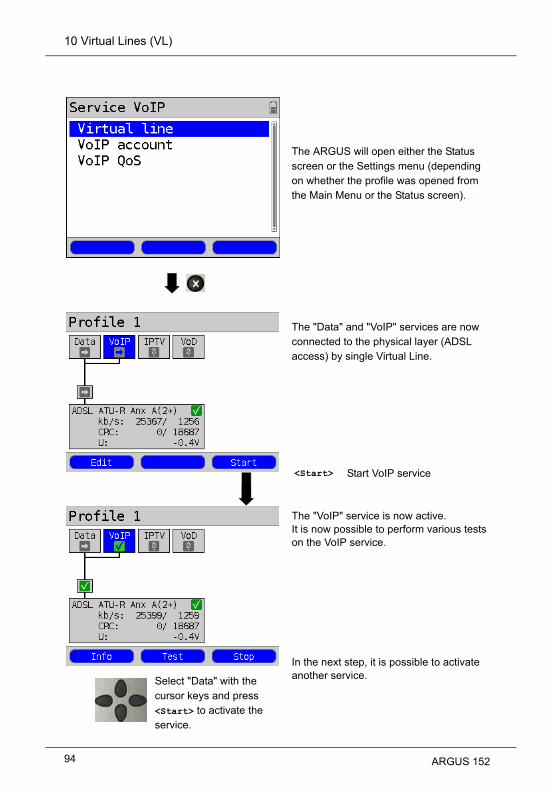
10 Virtual Lines (VL)
Select "Data" with the cursor keys and press <Start> to activate the service.
The ARGUS will open either the Status screen or the Settings menu (depending on whether the profile was opened from the Main Menu or the Status screen).
The "Data" and "VoIP" services are now connected to the physical layer (ADSL access) by single Virtual Line.
<Start>
The "VoIP" service is now active. It is now possible to perform various tests on the VoIP service.In the next step, it is possible to activate another service.
Start VoIP service
94 ARGUS 152

10 Virtual Lines (VL)
The "Data" and "VoIP" services are active. It is now possible to perform various tests on both the "Data" and the "VoIP" services.
The displays and operation of IPTV and VoD (Video on Demand) services are like those of VoIP.
Other examples of different Virtual Line assignments:
Example 1:
Example 2:
One Virtual Line is connected to the Data service and another to the VoIP service.The Virtual Line for VoIP can use different protocol data from that of the Virtual Line for Data.A Virtual Line was configured for the Data, VoIP, IPTV and VoD services. In this example, the IPTV and VoD services are active.
In the case of the IPTV service it is possible to setup up to four Virtual Lines.The ARGUS will however display these together as a single Virtual Line.For more details, see the chapter on IPTV (page 177).
ARGUS 152 95

10 Virtual Lines (VL)
t
Example 3:In this example, each service has been assigned a Virtual Line. Since the ARGUS is in Bridge mode, these services cannot be performed.
10.4 Virtual Line Settings
Setting Explanation
Virtual Profile 1 to 20
Protocol Selection of the transfer protocol that the ARGUS should use for the tes
(e.g. for an IP test).Default setting: PPP
The settings - regardless of whether the "ATM with Ethernet" or "ATM without Ethernet"
protocol is used - will be handled under the heading ATM.
ATM: Settings for Asynchronous Transfer Mode
VPI/VCI VPI:VCI:
Enter Virtual Path IdentifierEnter Virtual Channel IdentifierRange: VPI: 0 to 127, VCI: 32 to 255Default setting: VPI: 1 and VCI: 32
Encapsula-tion
Selection of the encapsulation of the packets to be sent: LLC or VC-MUX.Default setting: LLC
Protocol ATM: Interfaces:
ATM with ETH ADSL VDSL ETH
IP Yes EoAIP IP
IP No IPoA
PPP Yes PPPoEPPPoE PPPoE
PPP No PPPoA
PPTP - - - PPTP
96 ARGUS 152

10 Virtual Lines (VL)
,
Ethernet Sets whether Ethernet over ATM will be used or not, see table above.Default setting: Yes
VLAN: VLAN (Virtual Local Area Network)
VLAN
Use VLAN: Specifies whether or not VLAN should be used:Default setting: No
ID: Identifier for the VLAN to which the frame belongs. Every
VLAN is assigned a unique number, the VLAN ID. A device
which belongs to the VLAN with the ID = 1, can
communicate with every other device in the same VLAN,
but not with a device in other VLANs (i.e. one with a
different ID such as 2).Range: from 0 to 4095Default setting: 0
Priority: User - priority information:An eight-level (3 bits) priority can be assigned to each
frame. In this manner, it is possible e.g. to give priority to
forwarding voice data (e.g. in the case of VoIP), while HTTP
data will be handled as a lower priority.Range: 0 to 7Default setting: 0
PPP Profile: PPP settings (Point-to-Point-Protocol)<Edit> Open PPP profile for editing
User name
Entry of the user name assigned (by the network operator):Use the keypad to enter the user name. Whenthe right softkey is pressed it assumes a different meaning and thus influences the entries made from the keypad (uppercase orlowercase letters, or digits).
ARGUS 152 97

10 Virtual Lines (VL)
Password Entry of the password assigned by the network operator, for more
information, see User Name.While entering the password the characters will remain visible until the
password is confirmed. Afterwards, the characters of the password will be
shown masked with "*".
Set the IP If “Yes”, the IP address entered as IP / own IP address (see below) will be
used for the connection.Default setting: No
Activation delay
After setting up the PPP connection, the ARGUS will first wait until the
period specified in the “activation delay” has elapsed before beginning a
test.Range: 2 to 10 secondsDefault setting: 2
Profile name Enter the name of the PPP profile
PPTP: PPTP settings (Point-to-Point-Tunneling Protocol)
Local server IP addressRange 0.0.0.0. to 255.255.255.255Default setting: 0.0.0.0
IP version: Internet Protocol version
Setting that specifies which IP version should be used.
IPv4:IPv6Dual:
Internet Protocol version 4, in accordance with RFC 791 Internet Protocol version 6, in accordance with RFC 2460If IPv6 is available, it will be used by default, if not the
ARGUS will switch to IPv4.Default setting: IPv4
IPv4: Internet Protocol version 4 - settings
IP mode Setting the assignment of the IP addresses
Static IP:DHCP client:
DHCP server:
DHCP auto:
Static IP addressesIP address assigned by the server (remote end)IP address assigned by the ARGUSARGUS checks whether there is a DHCP server in the
network. If yes, the IP address will be assigned by the
server. Otherwise, the ARGUS will assign the address.Default setting: DHCP Client
98 ARGUS 152

10 Virtual Lines (VL)
Local IP Address
Own local IP address of the ARGUSRange: 0.0.0.0 to 255.255.255.255Default setting: 0.0.0.0 (see RFC 3330 regarding assignment)
IP netmask IP netmask Range: 0.0.0.0 to 255.255.255.255Default setting: 255.255.255.0 (see RFC 3330 regarding assignment)
Gateway IP Gateway IP addressRange: 0.0.0.0 to 255.255.255.255Default setting: 0.0.0.0 (see RFC 3330 regarding assignment)
DNS server DNS server 1 DNS server 2Entry of the DNS server's IP address(DNS = Domain Name System)Range: 0.0.0.0 to 255.255.255.255Default setting: 0.0.0.0 (see RFC 3330 regarding assignment)
DHCP client DHCP Timeout (setting of how long to wait for the IP address):Range: 1 to 9999 secondsDefault setting: 20
DHCP Vendor ID:- Format: Selection of the format: ASCII or hexadecimal- ASCII data: Enter the DHCP Vendor ID in ASCII formatDefault setting: ARGUS, for more information see "User name" on page 97
- HEX data: Enter the DHCP Vendor ID in hexadecimal format; for more information see "MAC address" on page 82
DHCP Vendor Info:- Format: Selection of the format: ASCII or hexadecimal- ASCII data: Enter the DHCP Vendor Info in ASCII formatDefault setting: ARGUS, for more information see "User name" on page 97
- HEX data: Enter the DHCP Vendor Info in hexadecimal format; for more
information see "MAC address" on page 82
DHCP User Class Information- Format: Selection of the format: ASCII or hexadecimal- ASCII data: Enter the DHCP User Class I. in ASCII format Default setting: ARGUS, for more information see "User name" on page 97- HEX data: Enter the DHCP User Class Information in hexadecimal format; for more information see "MAC address" on page 82
ARGUS 152 99

10 Virtual Lines (VL)
r
.
t
DHCP User-defined Option (creating a user-specific DHCP option)- Option number Range: 0 to 255 Default setting: 255 = off- Format: Selection of the format: ASCII or hexadecimal- ASCII data: Enter the DHCP Userdef. Option in ASCII format Default setting: ARGUS, for more information see "User name" on page 97- HEX data: Enter the DHCP User-defined Option in hexadecimal format, fo
more information see "MAC address" on page 82
DHCP server Options for the DHCP server:- Start and End IP addresses Range: 0.0.0.0 to 255.255.255.255 Default setting: (see RFC 3330 regarding assignment) Start: 192.168.10.30 End: 192.168.10.40- Name of the domain, for more information see "User name" on page 97- Reserve time of the IP addresses Range: 1 to 99999 hoursDefault setting: 240
Data Log Data log on or offThis setting must be "ON“ in order to send a trace file to a PC see page 54
After a Virtual Line has been terminated by the associated service or the
physical layer, the ARGUS will enquire whether the trace file should be sen
to the PC. In order to send the trace file, the Trace/remote (see page 330)
function must be active and the ARGUS must be connected to a PC using
the mini-USB.As an example, if data Log is activated for Virtual Line 1, only Virtual Line 1
will be recorded. If a Virtual Line is configured for multiple services and data
log is activated, all of this Virtual Line's data will be recorded.Default setting: Off
Profile name Enter the name of the VL profile.
100 ARGUS 152

10 Virtual Lines (VL)
o
10.5 Display the Protocol Statistics
Continuation on
next page
Depending on the access mode and protocol, the ARGUS will display the BRAS, IP, PPP, ATM or Ethernet statistics.
The physical line, the Virtual Line and the Data service are active.
BRAS information:The ARGUS displays (for the PPP protocol only) the BRAS (Broadband Remote Access Server) information:- AC (Access Server): Name of the server- Service name: Name of the service
<Info> Display DSL events
<Stop> Deactivate physical layer, VL and data
Using the cursor keys switch to the Virtual Line.
One after the other
and
Displays the ARGUS MAC addresses:Line, LAN, ETH, see alspage 110 f.
<IPv4> Display the configuration assigned by the server.
ARGUS 152 101

10 Virtual Lines (VL)
PPP information:The ARGUS will display the number of PPP packets and bytes received (Rx) and sent (Tx).Ethernet:The ARGUS will display the number of Ethernet frames received (Rx) and sent (Tx) and the number of bytes and errors.
Display commands
<PPP> The <PPP> softkey is used to open a PPP trace in which the sequence of PPP messages will be shown.
< = command sent from the ARGUS
> = command sent from the DSLAM
<Time> The <Time> is used to tag (timestamp) the individual messages with times from the ARGUS system clock.
Continuation on
next page
102 ARGUS 152

10 Virtual Lines (VL)
Table:
- PADI:PPPoE Active Discovery Initiation
- PADO:PPPoE Active Discovery Offer
- PADR:PPPoE Active Discovery Request
- PADS:PPPoE Active Discovery Session confirmation
- PADT:PPPoE Active Discovery Termination
- IPv6:IPv6 Control Protocol
- LCP:Link Control Protocol
- IPCP:Internet Protocol Control Protocol
- PAP:Password Authentication Protocol
ack. = acknowledge
auth. = authentication
conf. = configuration
nak. = not acknowledge
prot. = protocol
rec. = received
rep. = reply
req. = request
rej. = rejected
2x
ARGUS 152 103

10 Virtual Lines (VL)
In the case of IPv6:
Assigned configuration:The ARGUS will display the IP configuration assigned by the server:- Global Unicast Address- Link Local Address
Assigned configuration:The ARGUS will display the IP configuration assigned by the server:- IP address received- Gateway IP address- DNS Server available
<IPv6> IPv6 information will be displayed.
<IPv4> IPv4 information will be displayed.
Use the cursor keys to scroll to additional information.
Close the results display.
Close the results display.
Depending on the IP version
<IPv4>
104 ARGUS 152

10 Virtual Lines (VL)
ARGUS 152 105

11 Services
11 Services
Four services are presented on the Status screen (see explanation on page 86).There is an entire group of IP tests that can be performed for each Service (see the table
below). Furthermore, it is possible to start and stop each service independently of the other
services.
An example of the display with the possible services
If a service is activated, a variety of tests can be started with <Test>. The tests that can be
performed for the various services are as follows:
<Edit> To assign the service a Virtual Line (VL) profile and configure the service.
<Profile> Configure profile.
<Start> Activate service. If the Virtual Line and physical layer are not yet activated, they will also be started automatically.
Services:
- IP ping - IP ping - IP ping - IP ping
- Trace route - Trace route - Trace route - Trace route
- HTTP download - VoIP call - IPTV - Video on Demand
- FTP download - VoIP wait - IPTV scan
- FTP upload - IPTV passive
- FTP server
106 ARGUS 152

11 Services
11.1 Display the Service Statistics
ARGUS - Status screenThe physical layer, Virtual Line and service are activated.
Use the cursor to select a service (in this example, Data)
<Info> Display how long the selected service has been activated.
If the VoIP service is selected, Info will display the VoIP call parameters, see page 171.
Exit the display and return to the Status screen.
ARGUS 152 107

12 Test Overview and Hotkey Assignment
12 Test Overview and Hotkey Assignment
Test Overview
Interface Test
ATU-R VTU-RAUT-R BR
VTU-R BR
ATU-R RT
VTU-R RTEthernet
Loopsee page 112
- - - - x
VPI/VCI scan, see page 116
x - x*1 x*1 -
ATM OAM ping,
see page 120x - x*1 x*1 -
IP ping see page 124
x x - x x
Trace routesee page 131
x x - x x
HTTP download,
see page 136x x - x x
FTP download,
see page 143x x - x x
FTP upload, see page 148
x x - x x
FTP server, see page 153
x x - x x
VoIP call / waitsee page 174
x x - x x
IPTVsee page 177
x x - x x
IPTV scansee page 192
x x - x x
IPTV passive, see page 199
- - - x x
VoDsee page 203
x x x x x
*1 = not on VDSL
Table of the tests possible on an xDSL or Ethernet access:
In order for the ARGUS to perform these tests (with the exception of the ATM tests: VPI/VCI scan, ATM OAM ping and Loop), you must first configure a Virtual Line. The confi-guration of a Virtual Line is described in the chapter devoted to Virtual Lines, see page 86.
108 ARGUS 152

12 Test Overview and Hotkey Assignment
Graphic functions:After setting up an xDSL access or a test, the following graphic functions can be used in the
result graphics:
HotkeyADSL/VDSL Line Scope TDR
Line qualification
Zoom Zoom Zoom Zoom
Cursor Cursor Cursor Cursor
- Measurement range
Measurement range
-
- - Pulse width -
- - Wire types/VoP -
- Probe - -
- Symmetry Impedance -
Settings x-axis Time/FFT Averaging Settings x-axis
Continue - - Continue
- Run/Hold Run/Hold -
Numeric key 2
Numeric key 3
Numeric key 4
Numeric key 5
Numeric key 6
Numeric key 7
Numeric key 8
Numeric key 9
ARGUS 152 109

12 Test Overview and Hotkey Assignment
Hotkey AssignmentThe ARGUS keypad can be used to call up or start the main functions and/or tests directly. The selection of hotkeys available depends on the type of access selected (in the table below on an xDSL or Ethernet):
Hotkey Service ADSL VDSL Ethernet
ARGUS-State x x x
Help hotkeys x x x
VPI/VCI scan x - -
IP ping x x x
Trace route x x x
HTTP download x x x
FTP download x x x
Trace/remote x x x
IPTV x x x
VoIP call x x x
Status screen x x x
x x x
x x x
x x x
The speed-dialling memory for numbers, settings (e.g. PPP user name, IP addresses etc.), profile / profile names, user-specific services, keypad infos and all of the test results stored in the ARGUS will be deleted if the settings have not been saved before hand, see page 333.
x x x
Numeric key 0
Numeric key 1
Numeric key 2
Numeric key 3
Numeric key 4
Numeric key 5
Numeric key 7
Numeric key 8
Numeric key 9
One after the
other
and
Quick access to the Access Menu
One after the
other
and
Displays ARGUS-specific information, such as ARGUS type, SW version, S/N., own MAC addresses, SW options etc.
One after the
other
and
Restore the saved settings, see page 333.
One after the
other
and
All settings will be reset to the default factory settings, see page 333.
110 ARGUS 152

12 Test Overview and Hotkey Assignment
Different hotkeys will be available depending on the type of access selected (in this
example ISDN, POTS and Copper Tests):
Hotkey Service BRI S/T
BRI U
POTS Cu TestsStatus
x x x x
x x x x
x x - -
x x - -
x x - -
x x x x
x x - -
x x x -
x x x x
x x - -
x x x -
x x x -
x x x x
x x x x
x x x x
The speed-dialling memory for numbers, settings (e.g. PPP user name, IP addresses etc.), profile / profile names, user-specific services, keypad infos and all of the test results stored in the ARGUS will be deleted if the settings have not been saved before hand, see page 335.
x x x x
Start the Test Manager x x - -
Numeric key 0 ARGUS-State
Numeric key 1 Help hotkeys
Numeric key 2 Start Service check (not on a leased line)
Numeric key 3 Start Supp. serv. test (not on a leased line)
Numeric key 4 Starting the Automatic Test
Numeric key 5 Send test results to a PC
Numeric key 6 Start the Test Manager
Numeric key 7 Open speed-dialling memory
Numeric key 8 Trace/remote
Numeric key 9 Start BERT
Level measurement
Call setup
One after the
other
and
Quick access to the Access Menu
One after the
other
and
Displays ARGUS-specific information, see page 110.
One after the
other
and
Restore the saved settings
One after the
other
and
All settings will be reset to the default factory settings, see page 333.
One after the
other
and
ARGUS 152 111

13 Loop
13 Loop
A loop can be setup on an Ethernet line. A loop will take all incoming Ethernet frames at Layer 1 (L1) and send them back to the sender unchanged. In the case of a loop on Layer 2 (L2) of the OSI model, the ARGUS swaps the source MAC address with the destination MAC address and then sends all the incoming Ethernet frames back.The following parameters are required for the Loop:Protocol-independent parameters:
ARGUS - Status screenIn this example: Ethernet Access
Test parameters
Loop
Continuation on
next page
Select the test to be configured(in this example, Loop).
Select a profile for editing. The selected profile will be marked blue in the display. The default profile will be marked in the display with a
. The ARGUS will use the parameters in the default (preset) profile to setup the Ethernet connection and for the loop.
The ARGUS will use the marked profile as the default profile and return to the Settings menu.
112 ARGUS 152

13 Loop
View and edit the marked parameters if necessary
Settings - Mode - Layerselect and edit.
Mode
Layer
Quit the menu without saving the changes.
Setting Explanation
Test parameters:
Loop:
Use the Loop Mode to set what should be looped. - only those packets sent to own MAC (promiscuous mode off) L1: Only loop packets sent to own MAC address and broadcast packets. L2: Only loop those packets sent to own MAC address. Broadcasts will be discarded. - loop all packets (promiscuous mode on) L1: All packets (including Broadcast packets) will be looped. L2: All packets - with the exception of Broadcast packets - will be looped. Broadcasts will be discarded.Default setting: only own MAC
This setting determines the OSI Model layer that will be used for the loop. - L1: In the case of loop, all incoming Ethernet frames on Layer 1 (L1) will be sent back to the sender unchanged. - L2: In the case of loop on Layer 2 (L2) of the OSI model, the ARGUS will swap the source MAC address with the destination MAC address and then send all incoming Ethernet frames back to the sender.Default setting: L2
ARGUS 152 113

13 Loop
Start Loop (Access Mode: Ethernet)
Continuation on
next page
Set up the Ethernet connectionThe profile shown in the display (in this example, Profile 1) will be used for the loop.
<Start> Activate Ethernet
<Info> Display the Ethernet connection parameters
<Test> Display the available tests
<Stop> Stop the Ethernet connection
<Config> Change the loop parameters, see Page 113
114 ARGUS 152

13 Loop
The loop is started:
Saving the resultsThe results of the Loop test are saved in the same manner as for an ADSL access, see
page 54.
Duration Current duration of the test.
Looped Displays the number of packets looped so far.
Looped in 1 sec.
Displays the number of packets looped during the current second.
Through-put
Displays the current data throughput per second.
MAC Address
Own MAC address of the loopeddevice (e.g. to enter in the TrafficGenerator).
<Status> Display the Status screen without stopping the test.
Duration Total test time
Looped Number of packets looped
Average Number of packets looped per second
<Status> Displays the Status screen.
ARGUS 152 115

14 ATM Tests
14 ATM Tests
The following ATM tests can only be performed on an ADSL interface. Other interfaces, such as VDSL or Ethernet are not based on ATM technology.
14.1 VPI/VCI Scan
In a VPI/VCI Scan, the ARGUS checks which VPI/VCI combinations are active on the
access under test: The ARGUS will send a test packet for each of the possible VPI/VCI
combinations and wait for a packet in response.The following parameters, which are stored in a profile, are required to perform a VPI/VCI
Scan (if a xDSL connection has already been setup, the connection parameters, e.g. the
ADSL mode and the target value, are blocked):
Protocol-independent parameters:
Select a profile for editing. The selected profile will be marked blue in the display. The default profile will be marked in the display with a
. The ARGUS will use the parameters in the default (preset) profile to setup the xDSL connection and for the VPI/VCI Scan.
The ARGUS will use the marked profile as the default profile and return to the settings menu.
Continuation on
next page
116 ARGUS 152

14 ATM Tests
Setting Explanation
Test parameters:
VPI/VCI Scan:
VPI Virtual Path IdentifierThis sets the VPI range, which the ARGUS will check during the VPI/VCI scan.Range: 0 to 255
Default setting: 0 to 8
VCI Virtual Channel IdentifierThis sets the VCI range, which the ARGUS will check during the VPI/VCI scan.Range: 32 to 65535
Default setting: 32 to 48
Number of scans
The number of scans. Range: 0 to 99
Default setting: 2
Timeout This sets the maximum amount of time that the ARGUS will wait for a response
from an ATM network node to a test packet which it sent.Range: 0.1 to 9.9 seconds
Default setting: 0.5 seconds
Test parameters
View and edit the marked parametersif necessary
VPI/VCI scan
ARGUS 152 117

14 ATM Tests
Start a VPI/VCI Scan
In the example, the access is set to ADSL and ATU-R is active.
The VPI/VCI Scan starts automatically.The ARGUS displays the VPI/VCI combination currently being tested and the last VPI/VCI combination that was found to be active (in the example, 1/32).
<Info> Display the ADSL connection parameters
<Test> Display the tests possible
<Stop> Stop the ADSL connection
<Config> The ARGUS will display the test parameters for the VPI/VCI Scan, see page 117.
<Status> Display the Status screen without stopping the test; see above.
Cancel the test.
Initialization
VPI/VCI Scan
118 ARGUS 152

14 ATM Tests
After the VPI/VCI Scan has been concluded, the ARGUS will show the VPI/VCI combinations active on the access under test.
Close the results displayFor information on saving the results, see IP Ping Page 130.
<Status> Display the Status screen
<New> Start a new VPI/VCI Scan
VPI/VCI Scan - results
Save the result?
ARGUS 152 119

14 ATM Tests
14.2 ATM-OAM Ping
In an ATM OAM ping test, the ARGUS checks the availabilit of individual ATM network
nodes or an ATM subnet. OAM is an acronym for "Operation, Administration and
Maintenance“ and is used for the monitoring and administration of ATM data transmissions.The following parameters, which are stored in a profile, are required to perform an ATM
OAM ping (if an ADSL connection has already been setup, the connection parameters, e.g.
the ADSL mode and the target value, are blocked):
Protocol-independent parameters:
Select a profile for editing. The selected profile will be marked blue in the display. The default profile will be marked in the display with a
. The ARGUS will use the parameters in the default (preset) profile to setup the xDSL connection and for the ATM OAM ping.
The ARGUS will use the marked profile as the default profile and return to the Settings menu.
Continuation on
next page
Test parameters
ATM OAM Ping
120 ARGUS 152

14 ATM Tests
Setting Explanation
Test parameters:
ATM OAM ping:
VPI / VCI Entry of the VPI and VCI for the ATM OAM pingRange: VPI: 0 to 255, VCI: 32 to 65535Default setting: VPI: 1, VCI: 32
Number of pings
This sets the number of test packets that the ARGUS will send. If you enter "0", the ARGUS will send packets continuously until the
ATM OAM ping is stopped manually.Range: 1 to 99999Default setting: 3
Timeout This sets the maximum amount of time that the ARGUS will wait for
a response from an ATM network node to a test packet which it
sent.Range: 0.1 to 9.9 secondsDefault setting: 1 second
OAM cell type F5 The loopback cell will be answered by the first ATM node of the
virtual channel. The loopback cell will be answered by the first ATM
node of the virtual channel. F5 loopback ete The loopback cell will be answered by the endpoint
of the virtual channel.Default setting: F5 loopback ete
View and edit the marked parameters if necessary
ARGUS 152 121

14 ATM Tests
Start ATM OAM ping
In the example, the access is set to ADSL and ATU-R is active.
The ATM OAM ping test will start automatically.The ARGUS will display the current number of test packets sent, the current number of packets in response and the VPI/VCI on which the ping test is currently being run.
<Info> Display the ADSL connection parameters
<Test> Display the tests possible
<Stop> Stop the ADSL connection
<Config> The ARGUS will display the test parameters for the ATM OAM ping, see page 121.
<Status> Display the Status screen without stopping the test; see above.
Cancel the test.
Initialization
ATM OAM Ping
122 ARGUS 152

14 ATM Tests
At the end of the ATM OAM ping, the ARGUS will automatically display the results. If the test has been set to "continuous", it must be stopped manually:
For information on saving the results, see IP ping Page 130.
- Number of packets sent
- Number of packets received
- Number of packets lost
- Minimum packet round-trip delay
- Maximum packet round-trip delay
- Average packet round-trip delay
<Status> Display the Status screen.
<New> Start a new ATM OAM ping test.
ATM OAM ping result
Save the result?
ARGUS 152 123
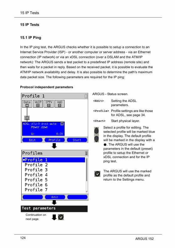
15 IP Tests
15 IP Tests
15.1 IP Ping
In the IP ping test, the ARGUS checks whether it is possible to setup a connection to an
Internet Service Provider (ISP) - or another computer or server address - via an Ethernet
connection (IP network) or via an xDSL connection (over a DSLAM and the ATM/IP
network): The ARGUS sends a test packet to a predefined IP address (remote site) and
then waits for a packet in reply. Based on the received packet, it is possible to evaluate the
ATM/IP network availability and delay. It is also possible to determine the path's maximum
data packet size. The following parameters are required for the IP ping:
Protocol independent parameters
ARGUS - Status screen.
<Edit> Setting the ADSL parameters.
<Profile> Profile settings are like those for ADSL, see page 34.
<Start> Start physical layer.
Select a profile for editing. The selected profile will be marked blue in the display. The default profile will be marked in the display with a
. The ARGUS will use the parameters in the default (preset) profile to setup the Ethernet or xDSL connection and for the IP ping test.
The ARGUS will use the marked profile as the default profile and return to the Settings menu.
Continuation on
next page
Test parameters
124 ARGUS 152

15 IP Tests
Setting Explanation
Test parameters:
IP ping:
IP address This is the address of the remote site. The ARGUS can save up to 10
IP addresses. The saved IP addresses are available to all of the
profiles.
The ARGUS shows the memory locations (a total of ten) available for storing IP addresses. Use the cursor keys to mark the memory location with the IP address that you wish to edit (in this example, the first memory location is marked (1/10)).
IP ping
View and edit the marked parameters if necessary
as name, IPv4 or IPv6 number
Continuation on next
page
The address can be entered as an IPv4 or IPv6 number, or as a name.Default setting: www.argus.info
<Edit> Open the marked IP address to edit it.
ARGUS 152 125

15 IP Tests
Enter the IPv4 or IPv6 address as a number.Use the numeric keypad to make the entry.
<Delete> Delete the character before the cursor.
to
When entering an IPv6 address, the key combinations can be used to enter the letters A to F.
Set the marked IP-address as the default address
Use the softkey on the right to shift the keypad (the softkey on the right assumes a different meaning when pressed):For information on entering the address as a name, see User name on page 97.
<12>ab> Entry of the digits 0 to 9 plus * and #
<ab>AB> To enter lowercase letters and @, /, -, .
<AB>12> To enter uppercase characters and @, /,- and .
Move the cursor within the line.
Number of pings Enter the number of test packets that the ARGUS should send to the
IP address. If you enter a zero ("0"), the ARGUS will send packets
continuously until the test is stopped manually.Range: 1 to 99999Default setting: 10
Pause This setting determines the amount of time that the ARGUS will wait
between sending test packets.Range: 0.1 to 9.9 secondsDefault setting: 1 second
Packet size This setting determines the size of the test packets.By varying the size, it is possible to determine the maximum data
packet size and the relationship between size and response time.Range: 36 to 55,555 bytesDefault setting: 84 bytes
IP address as an IPv4 number
IP address as an IPv6 number
126 ARGUS 152

15 IP Tests
Start IP ping (in the example, Access mode ATU-R, already active):
Set up the serviceThe profile shown on the display will be used for the IP ping (in this example, Profile 1).
If no xDSL or Ethernet connection has been setup, a connection will be setup automatically at this point using the default profile (see page 40).
The Data service and ADSL connection are active.
Fragmentation This parameter sets the fragmentation:Default setting: on
on Depending on the network (or router), test packets
may be divided into multiple packets.
off Fragmentation is not permitted, i.e. the test packets
may be rejected by the network (or router). In this
case, the ARGUS will not receive a packet in reply.
auto The ARGUS determines the maximum packet size for
the path to the destination address (Path-MTU) and
splits the test packet into smaller packets. These can
then be sent with the minimum of delay (since the
network/router need not fragment the test packet).
<Edit> Assign Virtual Lines to the Data service.
<Info> Duration of the activation
<Test> Open test selection
<Stop> Deactivate service
Continuation on
next page
ARGUS 152 127

15 IP Tests
n
The ARGUS displays the address stored in the profile.
e.g. select IP ping
<Config> Change the IP ping parameters, see page 125.
Select the IP address to use for the ping; the default address is marked with an .
<Edit> Open address for editing, see page 125.
<Status> Display the Status screen without stopping the test.
In this example, a ping test is being ruon a line using the IP version IPv4. The test would be run in a similar manner on a line with IPv6.
Continuation on
next page
128 ARGUS 152

15 IP Tests
The IP ping will start automatically.During the IP ping, the display shows:
After the test has run, the ARGUS will display the results:
- Number of test packets sent
- The number of packets in reply
- Minimum time in ms
- Maximum time in ms
- Average time in ms
<Destinat.> Displays the URL and IP address.
<Status> Display the Status screen without stopping the test.
Test CanceledThe ARGUS will display the results collected thus far and will inquire whether to save them (see page 130).
- Number of packets sent
- Number of packets received
- Number of packets sent again
- Checksum error
- Faulty packets received
- Minimum packet round-trip delay in ms
- Maximum packet round-trip delay in ms
- Average packet round-trip delay in ms
<Destinat.> Displays the URL and IP address.
<Status> Display the Status screen without stopping the test.
<New> Start a new IP ping test
Continuation on
next page
IP ping
IP ping results
ARGUS 152 129

15 IP Tests
“Sending the Trace file to a PC”, see page 100.A new test can be started if required. The xDSL connection and the service are still setup (to clear the connection down, press <Stop> in the status display).
IP ping – Error messages
If an error occurs, the ARGUS will display an error message.
For a description of the error messages, please see the appendix, page 352 et seq.
<Yes> The ARGUS will save the result of the IP ping test in the first available memory location in the internal memory (see page 326).
<No> The ARGUS will discard the results and return to the previous selection menu.
<Status> Displays the Status screen.
130 ARGUS 152

15 IP Tests
15.2 Trace Route
In an IP Trace route test, the ARGUS sends test packets and then displays a list of all of the
network nodes (hops) and their response times on the way to the destination address. This
information can then be used to precisely locate delays in the network.The following parameters (which are stored in the profile) are required for the IP Trace
route test:
Protocol-independent parameters:
ARGUS - Status screen
<Edit> Setting the ADSL parameters.
<Profile> Profile settings are like those for ADSL, see page 34.
<Start> Start physical layer
Select a profile for editing. The selected profile will be marked blue in the display. The default profile will be marked in the display with a
. The ARGUS will use the parameters in the default (preset) profile to setup the Ethernet or xDSL connection and for the Trace route test.
The ARGUS will use the marked profile as the default profile and return to the Settings menu.
Test parameters
Trace route
Continuation on
next page
ARGUS 152 131

15 IP Tests
Setting Explanation
Test parameters:
Trace route:
IP address The IP address of the destination node can be entered as an IP
number or as a name (URL) (for instructions, see IP Ping / IP
address on page 126).Default setting: www.argus.info
Maximum hops This sets the maximum number of hops that will be taken in the
path to the destination node.Range: 1 to 25Default setting: 25
Probes This sets the number of attempts that will be made to get a
response from a network node.Range: 1 to 10Default setting: 3
Timeout This sets the maximum amount of time that the ARGUS will wait for
a response from a network node.Range: 0.05 to 9.9 secondsDefault setting: 3 seconds
Edit the marked parameters if necessary
132 ARGUS 152

15 IP Tests
Start Trace Route
(In the example: Access mode ATU-R, already active)
Set up the service.The profile shown on the display will be used for the Trace route test (in this example, Profile 1).
If no xDSL or Ethernet connection has been setup, a connection will be setup automatically at this point using the default profile (see page 40).The Data service and ADSL connection
are active.
<Edit> Assign a Virtual Line to the Data service.
<Info> Duration of the activation
<Test> Open test selection
<Stop> Deactivate service
e.g. select Trace route
<Config> Change the Trace route parameters, see page 131.
Continuation on next
page
ARGUS 152 133

15 IP Tests
s
.
g
)
ess.
out
results d asks
The ARGUS displays the IP address or
URL stored in the profile.
The Trace route test will start automatically.During the Trace route test, the display shows:
Display after the Trace route has been run:
Select the address to use for the Trace route test; the default addresis marked with an .
<Edit> Open the address to be edited, for more information, see page 125
In this example, a Trace route is beinrun on a line with IP version IPv4. The test would be run in a similar manner on a line with IPv6.
- The current hop and probe (in the example 1 -3: i.e. first hop and 3rd probe
- Response time of the hop in the current probe (0.035 seconds)
- The IP address of the current hop; in thisexample, 217.0.116.223
<Destinat.> Displays the URL and IP addr
<Status> Display the Status screen withstopping the test.
Cancel TestThe ARGUS displays the testdetermined up to this point anwhether it should save them.
- All the hops and their average responsetime are displayed.
<Detail> Displays the IP address of the hop as a name (if possible).The details of the hop, which is at the top of the list shown above, will be displayed (in this example, hop 1).
Initialization
Trace route
Trace route result
134 ARGUS 152

15 IP Tests
Close the results display.Save the Trace route results, also see IP ping (seepage 130).Sending the Trace file to a PC (see page 100).
Save the result?
ARGUS 152 135

15 IP Tests
15.3 HTTP Download
In the HTTP download test, the ARGUS will attempt to download data from a web site or
file. The ARGUS will display the current "net download rate", the user data of the IP
packets, and once the HTTP download is over the average speed (in the case of multiple
download attempts). The following parameters (which are stored in the profile) are required
for the HTTP download:
Protocol-independent parameters:
ARGUS - Status screen.
Since it is not possible to accurately determine the transmission speed if the duration of the download test is less than 10 seconds, you should download a reasonably large file (taking into consideration the access speed). If the test duration is less than 10 seconds, the ARGUS will not show any data rate or time at the end of the test.
<Edit> Setting the ADSL parameters.
<Profile> Profile settings are like those for ADSL, see page 34.
<Start> Start Physic (physical layer)
Select a profile for editing. The selected profile will be marked blue in the display. The default profile will be marked in the display with a
. The ARGUS will use the parameters in the default (preset) profile to setup the Ethernet or xDSL connection and for the HTTP download test.
The ARGUS will use the marked profile as the default profile and return to the Settings menu.
Continuation on
next page
Test parameters
136 ARGUS 152

15 IP Tests
Select HTTP download.Ten user-defined server profiles are available which will also be used for both the FTP download and upload tests.
Edit the marked server profile.
Edit the marked parameters if necessary
ARGUS 152 137

15 IP Tests
Setting Explanation
Test parameters:
HTTP download:
Server profile:
A total of up to 10 user-defined server profiles can be created. These server profiles will then be available for the HTTP download, FTP download and the FTP upload tests. The profiles hold all of the parameters required for the HTTP download, FTP download and the FTP upload.
Server address
Enter the IP address or URL of the server from which the ARGUS should download the file. In the case of an Upload test: Enter the upload destination (server address) to which the ARGUS should send the data.For information on the softkeys, see page 125.
Download filename
The name of the file that the ARGUS should retrieve in the download test (HTTP download or FTP download). When entering a www address alias, please see page 139)For information on the softkeys, see page 125.
Upload filename
The filename under which the data – sent in the FTP upload test – should be saved on the server.Default setting: file
Upload file size
Sets the size of the file that the ARGUS will send in the FTP upload test.Range: 0 to 999 999 999 bytesDefault setting: 1 000 000 bytes
User name Entry of the user name for the (FTP or HTTP) server.For more information on the operation, see page 125.
Password Entry of the password for the (FTP or HTTP) server.For more information on the operation, see page 125.
Number of up-/downloads
The number of times that the ARGUS will retrieve the data from the source address in a Download test. In the case of an Upload test: This sets how often the ARGUS will send the data of the file to the destination. "Zero“ means continuously. In which case, the test must be terminated manually.Range: 1 to 9 999 (0 = continuous)Default setting: 3
Number of parallel downloads
The number of packets into which the requested download should be divided and downloaded in parallel (see page 139). Range: 1 to 10 Default setting: 3
Profile name Entry of a name for the profile
138 ARGUS 152

15 IP Tests
If an alias www address is entered as the "Source/Destination" address, the
ARGUS will "only" download the one HTML page during the HTML download
test. The ARGUS does not evaluate the HTML code, so any link to a “true” www
address will be ignored. In this case, the ARGUS will not display an error
message since the “Source/Destination” address specified will have been loaded
without error.When entering the “Source” address (server address and download filename)
make certain that you use the correct notation (upper and lower case), otherwise
the ARGUS will report an Error 301 (Moved Permanently) or Error 404 (Not
Found).If the ARGUS requests multiple downloads, it will reduce the number of
downloads requested to suit the number of downloads supported by the server.
This may result in a deviation from the parameters set. This can, for example, be
the case if the size of the requested file is unknown.
Where the name of the file to be downloaded exceeds the maximum permissible
length, it is possible to get around this by using the "Server" field for part of the
address.The server name may be up to 80 characters long while the file name may be 60
characters long.
ARGUS 152 139

15 IP Tests
Start HTTP download (in this example: Access mode ATU-R, is already active)
Set up the service.The profile shown on the display will be used for the HTTP download (in this example, Profile 1).
If no connection has been setup, a connection will be setup automatically at this point using the default profile (see
page 40).
<Edit> Add a Virtual Line to the Data service.
<Info> Duration of the activation
<Test> Open test selection
<Stop> Deactivate service
e.g. select HTTP download
<Profile> Display the available HTTP download profiles profile, see page 137.
Continuation on
next page
140 ARGUS 152

15 IP Tests
Select the server profile: (The default is marked with an ).
The HTTP download will start automatically.During the HTTP download, the display
shows:
<Edit> Edit the marked profileFor information on changing the individual settings, see page 138.
- Current download / Total downloadsIn the example, the first download attempt of a total of three (1/3) is shown.
- The amount of data already loaded (in the example, 10%)
- Current net download rate (in the example, 20.662 Mbit/s)
- The number of bytes already loaded (in the example, 59.922 MB)
- Size of the file to be downloaded (in the example, 95.367 MB)
- Current loading time in h:min:s
- Remaining loading time in h:min:s
- Number of parallel downloads
<Status> Display the Status screen without stopping the test.
Cancel the test.
Initialization
HTTP download
ARGUS 152 141

15 IP Tests
Display results:
Close the results displayFor information on saving the HTTP download results, see page 129.“Sending the Trace file to a PC”, see page 100.
<Status> Display the Status screen
<New> Start a new HTTP download
- Calculated average speed of all of the downloads (in the example, 20.847 Mbit/s)
- Size of file loaded (in the example, 95.367 MB)
- Average time required for a download in h:min:s
- Maximum parallel downloads
- Configured parallel downloads
HTTP download results
Save the result?
142 ARGUS 152

15 IP Tests
15.4 FTP Download
In the FTP download test, the ARGUS will attempt to download a file. The ARGUS will
display the current net download rate, the user data of the IP packets, and once the test is
over the net average speed (in the case of multiple download attempts). The following
parameters (which are stored in the profile) are required for the FTP download:
Protocol-independent parameters:
ARGUS - Status screen.
<Edit> Setting the ADSL parameters.
<Profile> Profile settings are like those for ADSL, see page 34.
<Start> Start Physic (physical layer)
Select a profile for editing. The selected profile will be marked blue in the display. The default profile will be marked in the display with a
. The ARGUS will use the parameters in the default (preset) profile to setup the Ethernet or xDSL connection and for the FTP download.
The ARGUS will use the marked profile as the default profile and return to the Settings menu.
Test parameters
FTP download
Continuation on
next page
ARGUS 152 143

15 IP Tests
Ten user-defined server profiles are available which will also be used for both the HTTP download and the FTP download tests.
In the case of a download test of less than 10 seconds, it is not possible to accurately determine the transmission speed. Consequently, it is advisable to download as large a file as is reasonable given the speed of the access. If the test duration is less than 10 seconds, the ARGUS will not show any data rate or time at the end of the test.
FTP download parameters, see page 138
Server address
IP address or URL of the FTP server
Download file name
The path and name of the file to be downloaded in the FTP download test
User name User name for the FTP server
Password The password for the FTP server
Number This sets how often the data at the “Source” address should be downloaded
Profile name Name of the server profile
View and edit the marked parameters if necessary
144 ARGUS 152

15 IP Tests
Start an FTP download (in this example: Access mode ATU-R, is already active)
Setup the serviceThe profile shown on the display will be used for the FTP download (in this example, Profile 1).
If no connection has been setup, a connection will be setup automatically at this point using the default profile (see page 40).
<Edit> Add a Virtual Line to the Data service.
<Info> Duration of the activation
<Test> Open test selection
<Stop> Deactivate service
e.g. FTP download
<Profile> Display the available FTP download profiles, see page 144.
Continuation on
next page
ARGUS 152 145

15 IP Tests
Mark the server profile (the default profile is marked with a ).
The FTP download will start automatically.During the FTP download, the display
shows:
<Edit> Edit the marked profileFor information on changing the individual parameters, see page 138.
- Current download / total downloadsIn the example the first download of a total of three (1/3) is shown.
- The amount of data already loaded (in the example, 13%)
- Current net average download rate (in the example, 20.548 Mbit/s)
- The number of bytes already loaded (in the example, 87.458 MB)
- Total size of file to be loaded (in the example, 95.367 MB)
- Current duration of the download in h:min:s
- Remaining loading time
- Number of parallel downloads
<Status> Display the Status screen without stopping the test.
Cancel the test.
Initialization
FTP download
146 ARGUS 152

15 IP Tests
s)
Display after the FTP download has
finished:
Close the results display.For information on saving the results, see IP ping page 129.Form more on sending the trace file to a PC, see page 100.
<Status> Display the Status screen.
<New> Start a new FTP download
- Calculated average speed of all the downloads (in the example, 20.823 Mbit/
- Size of file loaded (in the example, 95.367 MB)
- Average time required for a download in h:min:s.
- Maximum parallel downloads
- Configured parallel downloads
FTP download results
Save the result?
ARGUS 152 147

15 IP Tests
15.5 FTP Upload
In an FTP upload, the ARGUS sends the data in a file to a server. The ARGUS will display the current net upload rate, the user data of the IP packets, and once the test is over the net average speed (in the case of multiple upload attempts). The following parameters (which are stored in the profile) are required for the FTP upload:
Protocol-independent parameters:
ARGUS - Status screen.
Select a profile for editing. The selected profile will be marked blue in the display. The default profile will be marked in the display with a
. The ARGUS will use the parameters in the default (preset) profile to setup the Ethernet or xDSL connection and for the FTP upload.
The ARGUS will use the marked profile as the default profile and return to the Settings menu.
<Edit> Setting the ADSL parameters.
<Profile> Profile settings are like those for ADSL, see page 34.
<Start> Start Physic (physical layer)
FTP upload
Test parameters
Continuation on
next page
148 ARGUS 152

15 IP Tests
Ten user-defined server profiles are available which will also be used for both the HTTP download and the FTP download tests.Edit the marked server profile.
In the case of an upload test of less than 10 seconds, it is not possible to
accurately determine the transmission speed. Consequently, it is advisable to
upload as large a file as is reasonable to the server given the speed of the
access. If the test duration is less than 10 seconds, the ARGUS will not show
any data rate or time at the end of the test.
FTP upload parameters, see page 138
Server address
IP address or URL of the FTP server
Upload file name
The path and filename under which the file that is sent in the test should be saved on the server.
Upload file size
The size of the file sent
User name User name for the FTP server
Password Password for the FTP server
Number Number of uploads
Profile name Name of the server profile
View and edit the marked parameters if necessary
ARGUS 152 149

15 IP Tests
Start FTP upload (in this example: Access mode ATU-R, is already active)
Set up the service.The profile shown on the display will be used for the FTP upload (in this example, Profile 1).
If no connection has been setup, a connection will be setup automatically at this point using the default profile (see page 40).
<Edit> Assign Virtual Lines to the Data service.
<Info> Duration of the activation
<Test> Open test selection
<Stop> Deactivate service
e.g. FTP upload
<Profile> Display the available FTP upload profiles, see page 149.
Continuation on
next page
150 ARGUS 152
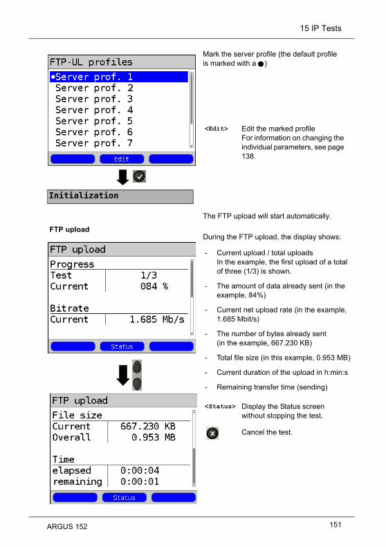
15 IP Tests
Mark the server profile (the default profile is marked with a )
The FTP upload will start automatically.
During the FTP upload, the display shows:
<Edit> Edit the marked profileFor information on changing the individual parameters, see page 138.
- Current upload / total uploadsIn the example, the first upload of a total of three (1/3) is shown.
- The amount of data already sent (in the example, 84%)
- Current net upload rate (in the example, 1.685 Mbit/s)
- The number of bytes already sent(in the example, 667.230 KB)
- Total file size (in this example, 0.953 MB)
- Current duration of the upload in h:min:s
- Remaining transfer time (sending)
<Status> Display the Status screen without stopping the test.
Cancel the test.
Initialization
FTP upload
ARGUS 152 151

15 IP Tests
Display results:
For information on saving the results, see IP ping page 129.For more on sending the trace file to a PC, see page 100.
- Calculated average bitrate of all uploads
- The size of the file sent
- The average time required for an upload
<Status> Display the Status screen
<New> Start a new FTP upload
FTP upload results
Save the result?
152 ARGUS 152

15 IP Tests
15.6 FTP Server
In FTP server mode, the ARGUS acts as a server for FTP requests. In this case, the ARGUS will handle both FTP download and upload requests. These requests can be sent by a second terminal (e.g. a second ARGUS) on an xDSL or Ethernet connection.In this manner, it is possible to perform an end-to-end test of the throughput and determine the highest average transfer rate attainable for this connection.The throughput test is illustrated in the following on an Ethernet interface.In this example, two ARGUS testers are used. One is used as an FTP server while the second requests an FTP download.ARGUS 1 - FTP ServerNo settings need to be made on the ARGUS that acts as the FTP Server. Simply start the FTP server single test on the selected interface. Start FTP Server (in the example: Ethernet is already active)
Continuation on
next page
Set up the service.The profile shown on the display (in this example, Profile 1) will be used for the FTP server.
If no connection has yet been setup, a connection will be setup automatically at this point using the default profile, see page 40.
<Edit> Assign a Virtual Line to the Data service.
ARGUS 152 153

15 IP Tests
Initialization
The ARGUS will use the IP address entered in own "local IP address" as the destination address (Server) for the second ARGUS.
<Status>
ARGUS 1 will now wait for an FTP request from a second terminal (in the example, a second ARGUS).The IP mode in the example is "static", the IP netmask is in the default configuration.
e.g. FTP Server
Display the Status screen without stopping the test.
154 ARGUS 152

15 IP Tests
ARGUS 2 - FTP Download / UploadAs far as the ARGUS that will issue the FTP requests (in this example, FTP download) is concerned, basically the same settings can be used as in the case of an FTP download test.Netmask and local (own) IP address (IP mode: static) should match the settings of ARGUS 1.Start an FTP Download:
Set up the service.The profile shown on the display (in this example, Profile 1) will be used for the FTP server.
Continuation on
next page
If no connection has yet been setup, a connection will be setup automatically at this point using the default profile (see page 40).
<Info>
<Test>
<Stop>
<Edit> Assign a Virtual Line to the Data service.
Duration of the activation
Open test selection
Deactivate service
ARGUS 152 155

15 IP Tests
Continuation on
next page
<Profile>
Mark the server profile (the default profile is marked with a ).
<Edit>
e.g. FTP Download
Edit the FTP Download parameters, see page 144.
Edit the marked profileFor information on changing the individual parameters, see page 138.
156 ARGUS 152
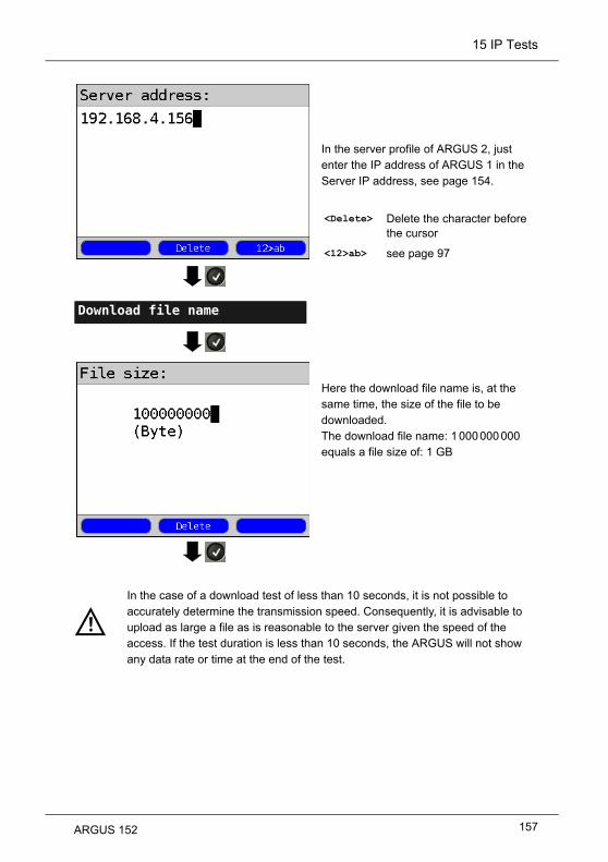
15 IP Tests
Download file name
In the server profile of ARGUS 2, just enter the IP address of ARGUS 1 in the Server IP address, see page 154.
<Delete>
<12>ab>
Here the download file name is, at the same time, the size of the file to be downloaded.The download file name: 1 000 000 000equals a file size of: 1 GB
In the case of a download test of less than 10 seconds, it is not possible to accurately determine the transmission speed. Consequently, it is advisable to upload as large a file as is reasonable to the server given the speed of the access. If the test duration is less than 10 seconds, the ARGUS will not show any data rate or time at the end of the test.
Delete the character before the cursor
see page 97
ARGUS 152 157

15 IP Tests
al
:s
FTP download
Server profile
Initialization
<Edit>
The FTP download will start automatically.
During the FTP download, the display
shows:
<Status>
Edit the marked profileFor information on changing the individual parameters, see page 138.
- Current download / total downloadsIn the example the first download of a totof three (1/3) is shown.
- The amount of data already loaded (in the example, 7 %)
- Current net average download rate (in the example, 91.367 Mbit/s)
- The number of bytes already loaded(in the example, 264.014 MB)
- Total size of file to be loaded(in the example, 1.999 GB)
- Current duration of the download in h:min
- Remaining loading time
- Number of parallel downloads
Display the Status screen without stopping the test.
Cancel the test.
158 ARGUS 152

15 IP Tests
s)
Display after the FTP download has finished:
Close the results display.For information on saving the results, see IP ping page 129.For more on sending the trace file to a PC, see page 100.
<Status> Display the Status screen.
<New> Start a new FTP download
- The calculated average speed of all the downloads (in this example, 91.774 Mbit/
- The size of file loaded (in the example, 844.829 MB)
- Average time required for a download in h:min:s.
- Maximum parallel downloads
- Configured parallel downloads
Save the result?
FTP download results
ARGUS 152 159

16 VoIP Tests
16 VoIP Tests
The ARGUS acts as a VoIP terminal with which a telephone (voice) call can be set up. The
ARGUS uses the Session Initiation Protocol (SIP) as the signaling protocol for VoIP. VoIP
calls can be set up with or without a registrar or proxy. The ARGUS can be used to setup a
VoIP connection (DSL telephony) via xDSL or Ethernet. The MOS/R-factor of the RTP data
stream will determined and displayed as an evaluation of the voice quality.Three "VoIP accounts (Profiles)" can be configured for use in VoIP telephony:
Protocol-independent parameters:
ARGUS - Status screen.
Select a profile for editing. The selected profile will be marked blue in the display. The default profile will be marked in the display with a
. The ARGUS will use the parameters in the default (preset) profile to setup the Ethernet or xDSL connection and for the VoIP test.
The ARGUS will use the marked profile as the default profile and return to the Settings menu.
<Edit> Assign a Virtual Line to the VoIP service.
<Profile> Profile settings are like those for ADSL, see page 34.
<Start> Start service
Continuation on
next page
Access parameters
Service VoIP
160 ARGUS 152

16 VoIP Tests
A total of 3 user-defined VoIP profiles can be configured.
Edit the marked profile.
<Edit> Edit the VoIP profile.
VoIP account
Edit the marked parameters if necessary
ARGUS 152 161

16 VoIP Tests
Setting Explanation
VoIP account settings:
VoIP: Up to 3 user-defined VoIP profiles can be created.<Edit> The selected profile will be opened for editing.
SIP User name User name for the registrar, for more information, see page 97.
Password Password for the registrar, for more information, see page 98.
Registrar Server
Use Registrar: Setting: yes or no.A registrar must also be used if an Internet Telephony Service Provider (ITSP) is used (in such case, you will dial a normal telephone number). A registrar is not needed if you dial a VoIP telephone directly, e.g. via its IP address or the SIP URI.Default setting: No
Outbound
Proxy/SBCUse proxy (SBC = Session Border Controller)This setting specifies whether or not to use outbound proxy. Default setting: No
Outbound Proxy/SBC: Address of the Proxy Server
Outbound Proxy/SBC Port: Port of the outbound proxy serverRange: 0 to 65535Default setting: 5060
SIP domain Configuration of the domain name for the “From” field in the SIP message (when using an ITPS).
Listen port The port used for the incoming SIP signaling. Range: 0 to 65535Default setting: 5060
Remote port The port used by the remote end: When using a registrar (see Registrar Server Setting on page 162), enter the port number of the Registrar/Proxy Server; otherwise, enter the port number of the remote end.Range: 0 to 65535 Default setting: 5060
Authentication Addtional xTU-R password used for proper authentica-tion with the registrar.For more information, see page 97
162 ARGUS 152

16 VoIP Tests
SIP
(Continuation)
Caller ID Optional entry of any text desired which will then be displayed on the called party's equipment instead of the caller's phone number.For information on the softkeys, see page 97.
User agent ID-string or terminal type which will be sent to the called party.Default setting: Argus152
Qualify Specifies whether or not the proxy server’s availability should be checked continuously. Default setting: No
Reg. Expire Specifies how long a registration with the registrar server is valid. Range: 10 to 6000 secondsDefault: 3600 seconds
Del. exist.registrar
Delete the registration with the registrar server. When set to "yes", the ARGUS will be exclusively registered with the registrar server.If it is set to "no", it will be put in the list of existing registrations. Default setting: Yes
Phone
Settings
RTP port
range
The SIP signaling and RTP data will be sent to different ports. The port range used for RTP can be configured for use e.g. with a router. Range: 0 to 65535Default: Start: 10 000 End: 20 000
Silencedetection
If this is set to “ON”, the ARGUS will not send speech packets when there is silence (a break in the speech). This can, however, lead to problems with the assignment of ports if there is a NAT router in the path. If this setting is set to "not used", the (remote) link partner will not be notified as to "silence detection" setting. The setting will, however, remain.Default setting: Off
ARGUS 152 163

16 VoIP Tests
Phone
Settings
(Continuation)
Jitter buffer Sets whether the size of the jitter buffer is static or adaptive. Default setting: static
static: Entry of the size of the static jitter bufferRange: 20 to 200 msnominal: 60 ms
adaptive: Entry of the minimum (min) and
maximum (max) sizes of the jitter buffer
and the initial value (init). Range: 20 to 600 msDefault setting:min: 60 msinit: 60 ms max: 120 ms
Codecs Preparation of a list of voice codecs to be used. If there
are multiple codecs in the list, the priority is determined
by the order in the list.
Switch between softkey sets
<> The marked codec will be moved down
one place in the list.
<> The marked codec will be moved up one
place in the list.
<Insert> A display of the still available voice
codecs will open. If a voice codec is
marked with a in this Codec
Selection list, it will be added to the
Codec Priority list (in the active list of
voice codecs)
<Delete> Delete the marked codec from the list
Apply the codec priorities
164 ARGUS 152

16 VoIP Tests
Phone
Settings
(Continuation)
DTMF
Settings
DTMF (Dual-tone multi-frequency) is a multi-frequency
dialling mode.Mode: DTMF mode settingsChoose one of the following settings "automatic", "SIP
Info", "RFC 2833" or "inband".Default setting: automaticDuration: The VoIP DTMF Time settingRange: 40 to 1000 msUp to 200 ms in increments of 10, 200 to 300 ms in
increments of 20, 300 to 1000 ms in increments of 100.
Default setting: 80 ms
Increase or decrease VoIP DTMF time.
STUN server Use STUN Use STUN: Setting: yes or no. If there is a NAT router between the ARGUS and the next remote end (gateway), you must use STUN so that the ARGUS can determine which IP address is seen for it (the ARGUS) by the other end.Default setting: No
STUN server STUN Server: Specifies the address of a STUN server which must be located in the same network (on the same level) as the remote end.
MOS threshold
Entry of the MOS threshold:The MOS value (Mean Opinion Score) is an evaluation of the quality of the speech data. The MOS quality scale ranges from 5 (excellent) down to 1 (bad). The ARGUS will compare the MOS value of the currently active VoIP connection to the MOS threshold value and will display "OK" - if the current MOS value is at least as good as the MOS threshold value - or "FAIL" - if it is not.Range: 1.0 to 5.0Default: 4.0
The MOS value determined here is the MOSCQE (Conversational Quality
Estimated). This value can be strongly influenced by the codec used.
Profile name
Enter or change the name of the edited VoIP profile.
Value 5 4 3 2 1
Voice quality excellent good fair poor bad
ARGUS 152 165

16 VoIP Tests
VoIP QoS (Quality of Service)
Layer 3DiffServ
Differentiated Services: Classification/Prioritization of IP packets (L3)
RTP
(ToS/DSCP)
ToS Type of ServiceField used to set the prioritization in the IP header of the user data (RTP), for more infomation, see page 126.Range: 0 to 0xFFDefault setting: 18
DCSP Differentiated Services Codepoint Field used to set the prioritization in the DS field (6 bits) of the user data (RTP), for more information, see page 126.Range: 0 to 0x3FDefault setting: 00
SIP
(ToS/DSCP)
ToS Type of ServiceField used to set the prioritization in the IP header of the SIP data (signaling), for more information, see page 126.Range: 0 to 0xFFDefault setting: 18
DCSP Differentiated Services Codepoint Field used to set the prioritization in the DS field (bits) of the SIP data (signaling), for more information, see. page 126.Range: 0 to 0x3FDefault setting: 00
Layer 2 VLAN prio
The VLAN prioritization on Layer 2 (L2) is an extension of the Ethernet header.
RTP VLAN
prio
VLAN prioritization of user data (RTP).Range: 0 to 7Default setting: 0
SIP VLAN
prio
VLAN prioritization of SIP data (signaling).Range: 0 to 7Default setting: 0
166 ARGUS 152

16 VoIP Tests
16.1 Start VoIP Telephony
(Example: ADSL access already active)Set up the service.The profile used to set up the xDSL connection (in this example, Profile 1) will also be used for VoIP telephony.
If no xDSL connection has been setup, a connection will be setup automatically at this point using the default profile (see
page 40).
<Edit> The default Virtual Line profile will be opened for editing.
<Info> Duration of the activation, see page 171.
<Test> Open test selection
<Stop> Deactivate service
e.g. select VoIP call
Continuation on
next page
ARGUS 152 167

16 VoIP Tests
Mark VoIP destination(default is marked with a ).Move the cursor down to select an empty line and add a new VoIP destination using <Edit>.
Set up a connectionThe ARGUS will display its "own call number" (From: 7087) and the subscriber number called (To: 87). The subscriber called has not yet accepted the call: display shows "Connecting!" and a yellow "CALL" icon.The subscriber called has accepted the call; the display shows “Connected!”. The ARGUS will determine the MOS value and will indicate whether the speech quality meets or exceeds the MOS threshold set (see page 165) - i.e. will display "OK" or "Fail". The ARGUS will also show the evaluation of the MOS value in accordance with ITU-T P.800 (in this example, "Good"). Furthermore, it will display the duration of the connection and the currently used voice codec (in this
example, G.711 A-law, see page 164).
<Edit> Open the VoIP destination number for editing
<Info> Display of the VoIP parameters.
<Status> Display the Status screen without stopping the test; see page 170.
<Volume> Opens the volume setting.Continuation on
next page
Initialization
Continuation on next page,
second screenshot.
168 ARGUS 152

16 VoIP Tests
Setting the volume:
Display of the other VoIP results:
<Extern> Headset operation
<Intern> Handset operation
<OK> Settings confirmed
Display MOS info:
-----
Current MOSAverage MOSMin./max. MOS valueIdeal MOS (MOS possible without interference, depends on Codec)Current and average R-Factor in accordance with ITU-T G.107
Return to the previous display.
Packet statistics:
-----
Packets received (Rx)Packets sent (Tx)Error counters:RTP dropRTP errorRTP jitter Rx:Current jitterAverage jitterMinimum jitterMaximum jitterRTP packets lost (Rx) (total, current, average, min. and max.)
Return to "outgoing call"
<Info>
Continuation on
next page
ARGUS 152 169

16 VoIP Tests
Content of RTCPDisplay of the statistics sent by the link partner:- Current jitter at the link partner (remote end) Rx (far)- Average jitter far (remote end)- Maximum and minimum jitter at the link partner- RTP packets lost at the link partner Rx (far): Total, current, average, min. and max.- Network delay calculated from the RTCP packet transfer time: current, average, min., and max.
If the message "no data" is displayed, RTCP is not supported by the link partner (remote end).The ARGUS will display the codecs supported by the link partner.
ARGUS - Status screen. The VoIP service still has a test active (indicated by the green "hammer" icon).
Open the “outgoing call" display
<MOS> Return to the "MOS info" display.
or
Display the Status screen without stopping the test.
<Status> In ARGUS Status, see page 168.
Use the cursor keys to select VoIP service
Continuation on
next page
170 ARGUS 152

16 VoIP Tests
The ARGUS will display how long the service VoIP has been active, as well as the user name and protocol used.
The ARGUS shows the registration details before, during and after the connection. The setting "Use Registrar" must be set to "yes" for this purpose.
<Test> Display the results summary
<Info> or
Display the VoIP call parameters.
<SIP> Display the registration details: Status codes, register IP, register used, Outbound Proxy/SBC and URI used etc.
<Log.> Displays the VoIP service SIP commands, see page 172.
Continuation on
next page
ARGUS 152 171

16 VoIP Tests
The ARGUS will display the service service SIP commands.
Other info ((see chapter I) VoIP SIP status codes page 359).
The ARGUS can be called while VoIP service is active. An incoming call will be indicated with yellow Call icon. The incoming call can be accepted or rejected.To have incoming calls accepted automatically, start the "VoIP wait" test, see page 175.
<Time> Appends a timestamp to all events.
The timestamp is based on the internal system clock of the ARGUS, see page 331
<Reject> Reject call.Switch to the Status screen.
<Accept> Accept call.Open the ARGUS-State.
Incoming call:
172 ARGUS 152

16 VoIP Tests
Display / Meaning
SIP Log Log showing the SIP methods exchanged and status codes.
Register state The ARGUS shows all of the important registration and registrar info in the Register state display.
VoIP Features at a Glance
During and after a successful registration:
During a call or a connection:
Display / Meaning
MOS value, Voice codec Current MOS value, current voice codec used.
SIP Log: Log showing the SIP methods exchanged and status codes.
INFO: MOS results: Threshold: Shows whether the value stayed within the preconfigured MOS threshold.
P.800: Evaluation in accordance with ITU-T P.800
MOS value: current/average/min./max.
R factor: current/average/min./ideal
INFO: RTP results: RTP packets: received / sent
RTP drop: RTP packets received but discarded by the jitter buffer.
RTP error: RTP packets received but defective.
RTP jitter Rx: current / average / min. / max. (calculated in accordance with RFC 3550 per sec.)
RTP packet loss Rx: current / average / minimum / maximum in percent
RTP packet loss total number:(RTP packets not received)
INFO: RTCP results:
RTP jitter remote end: current / average / minimum / maximum
(The content of the RTCP packets will be displayed if this is sup-ported by the remote end.)
RTP Packet Loss - remote end: current / average / minimum / maximum in percent
RTP packet loss - remote endTotal number
Network delay: current / average / minimum /maximum (Calculated on the basis of RTCP packets exchanged)
ARGUS 152 173

16 VoIP Tests
16.2 VoIP Wait
When running the "VoIP Wait" test, the ARGUS behaves like a VoIP telephone.To run the "VoIP Wait" test, the parameters for "VoIP call" (see page page 162) and "VoIP Wait" must be configured:
Continuation on
next page
Set up the service.The profile used to set up the xDSL connection (in this example, Profile 1) will also be used for "VoIP wait".
<Edit>
If no xDSL connection has been setup, a connection will be setup automatically at this point using the default profile (see page 40).
<Config>
The default (preset) Virtual Line profile will open for editing.
Opens the call accept. mode for "VoIP wait".
174 ARGUS 152

16 VoIP Tests
The "VoIP wait" test supports
- Automatic - Echo testDefault setting: Automatic
Start VoIP wait
Continuation on
next page
Initialization
The VoIP service and the ADSL connection are active.
The ARGUS will use the user name entered under the SIP parameters as its own number, see page 162.
Select "VoIP wait"
ARGUS 152 175

16 VoIP Tests
The ARGUS will wait for a VoIP call.
<Status>
The ARGUS will accept the call (see setting page 175) automatically.The call (connection) parameters are explained in the section on VoIP calls, see page 168 et seq..
Call clearing:
The connection is cleared down in the same manner as it is after an IP ping. However, pressing the "Cancel" key once will only clear down the connection (if there is one). The ARGUS will remain registered with the registrar (VoIP service active) so the ARGUS can still be called (an incoming call can be rejected or accepted). Deactivate the VoIP service to clear the registration with the registrar. In this case, the existing connection will, however, not be cleared down.
Open ARGUS Status, see page 168.
176 ARGUS 152

17 IPTV Tests
17 IPTV Tests
17.1 IPTV
The ARGUS requests a data stream from a server (Depending on the type of access, the
ARGUS will substitute for a settop-box (STB) or modem and STB) and checks the
regularity of the incoming packets, the loss of packets and the programme's switch on or
zapping time. Up to three user-defined "IPTV Profiles“ can be configured (when the xDSL
connection has already been setup the access parameters, e.g. the ADSL mode and the
target value are locked):
Protocol-independent parameters:
ARGUS - Status screen.The IPTV-STB emulation is performed using the "IPTV" service. The following example shows the procedure and considers its special aspects.
<Edit> Assign Virtual LinesVirtual Lines to the IPTV service.
<Profile> Profile settings are like those for ADSL, see page 34.
<Start> Start service
Select a profile for editing. The selected profile will be marked blue in the display. The default profile will be marked in the display with a
. The ARGUS will use the parameters in the default (preset) profile to setup the Ethernet or xDSL connection and for the IPTV test.
The ARGUS will use the marked profile as the default profile and return to the Settings menu.
Continuation on
next page
Test parameters
IPTV
ARGUS 152 177

17 IPTV Tests
A total of 3 user-defined IPTV profiles can be configured.
Edit marked IPTV profile
Setting Explanation
Test parameters:
IPTV: Up to 3 user-defined IPTV profiles can be created.<Edit> The selected profile will be opened for editing.
Channel selection
The channel list can be used and edited for all profiles. Up to 250
channels can be created. A configuration can also be conveniently
prepared using the WINplus/WINanalyse software on a PC.Selection of the TV test channels for the IPTV test:<Edit> The channel is opened for editing.
Multicast IP Entry of the multicast IP. Range: 0.0.0.0 to 255.255.255.255Default setting: 224.0.0.0
View and edit the marked parameters if necessary
178 ARGUS 152

17 IPTV Tests
Port Entry of the port Range: 0 to 65535Default setting: 0
Alias name Entry of a station name for the IPTV channel
IGMP version Version of the management protocol to log on/off of a multicast group.Range: 2 to 3Default setting: 3
Threshold Setting of the threshold values for the IPTV test. If these values are exceeded during the IPTV test, the test will display
the assessment "FAIL"; otherwise "OK" will be displayed.If an "*" is entered, the corresponding threshold will not be checked.
IGMP latency Setting of the latency threshold value (the delay in starting the
programm).Range: 0 to 25 000 msDefault setting: 500 ms
Sync error Setting of the threshold value for the sync error.Range: 0 to 10 000Default setting: 0
PCR jitter Setting the threshold values for PCR jitter.Range 0 to 2 000 msDefault setting: 8 ms
Error indication
Setting of the threshold value for the Error indication.Range: 0 to 10 000Default setting: 0
CC error Setting of the threshold value for the CC error.Range: 0 to 10 000Default setting: 0
CC error ratio
Setting of the threshold value for the CC error ratio.Range: 0.00% to 100.00%Default setting: 0.10%
Audio bytes Setting of the threshold value for the Audio bytes.Range: 0 to 6 553 600Default setting: 0
Video bytes Setting of the threshold value for the Video bytes.Range: 0 to 6 553 600Default setting: 0
ARGUS 152 179

17 IPTV Tests
RTP jitter Setting of the threshold value for RTP jitter.Range: 0 to 2 000 msDefault setting: 100 ms
RTP sequence error
Setting of the threshold value for the RTP sequence error.Range: 0 to 10 000Default setting: 0
Current RTP loss ratio
Setting of the threshold value for the current RTP loss ratio.Range: 0.00 % to 100.00%Default setting: 0,00%
Total RTP loss ratio
Setting of the threshold value for the RTP loss ratio for the entire test.Range: 0.00% to 100.00%Default setting: 5.00%
Profile name Entry of a name for the IPTV profile.
180 ARGUS 152

17 IPTV Tests
17.1.1 Multiple Virtual Lines
The ARGUS can use up to 4 Virtual Lines for the IPTV service. In this case, the IGMP VL is used for the transport of the IGMP protocol and Virtual Lines 1 to 3 are used to receive the video/audio streams.The selected Virtual Line Profile in overview.
Selected the Virtual Line Profile 2 for the service IPTV.
<Edit> Edit the selected virtual profile (in this example, Virt. Profile 1), see page 96.
<More VLs> Open the Virtual Line selection for the IPTV service.
<Insert> Insert of additional Virtual Line Profiles.
ARGUS 152 181

17 IPTV Tests
Switch between softkey sets
<Delete> Remove the selected virtual profile (in this example, Virt. Profile 2) from the list.
<Insert> Insert another Virt. Profile.
<Edit> Edit the selected virtual profile (in this example, Virt. Profile 1), see page 96.
<> The marked profile will be moved down one place in the list.
<> The marked profile will be moved up one place in the list.
182 ARGUS 152

17 IPTV Tests
Start IPTV
Set up the service.The profile used to set up the xDSL connection (in this example, Profile 1) will also be used for IPTV.
Activate the IPTV service.If no xDSL connection has been setup, a connection will be setup automatically at this point using the default profile (see page 40).
<Edit> Assign a Virtual Line to the IPTV service or edit it.
<Info> Duration of the activation
<Test> Open test selection
<Stop> Deactivate service
<Profile> Display the IPTV profile, see page 178.
Continuation on
next page
ARGUS 152 183

17 IPTV Tests
t
Select the IPTV profile (the default profile is marked with a ).
The IPTV test will start automatically.During the test, the ARGUS displays the selected IPTV channel, the duration of the test and the current bitrate. If the measured values exceed the threshold limits in the settings, the ARGUS will report that the IPTV test failed (FAIL); otherwise it will display "OK". The ARGUS will continue to display “FAIL” until the measured value returns to a value less than the limit value once again.
<Edit> Edit the marked profileFor information on changing the individual parameters, see page 178.
<Channel> Select a new channel
<Status> Display the Status screen withoustopping the test.
<Total> Display all of the IPTV statistics.
Cancel the test.
Initialization
IPTV test
Continuation on
next page
184 ARGUS 152

17 IPTV Tests
Display:
Display (MDI in acc. with RFC 4445):
Display:
- Current bitrate
- Number of packets lost during the test
- Display the packet loss ratio as a percentage
<Detail> Open the IPTV details
- Display the current delay factor in ms
- Display the minimum delay factor in ms
- Display the maximum delay factor in ms
- Display the average delay factor in ms
- Display the Media Loss Rate (MLR) as a percentage
- Display the test duration
- Display the selected channel name
- Display the IP address of the station
- Display the port of the station
- Display the IGMP latency (switch on time of the programme) in ms
<RTP/UDP> Open the RTP/UDP details, see page 186.
Continuation on
next page
ARGUS 152 185

17 IPTV Tests
Display
Display:
Display:
- Display the selected IPTV protocol
- Display the DSL-CRC error counter (not on Ethernet), see page 43.
- Number of packets currently lost
- Minimum number of packets lost
- Maximum number of packets lost
- Average number of packets lost
- Total number of packets lost during the test
<MPEG2> Open the MPEG2 details, see page 187.
- Display the current packet loss ratio
- Display the minimum packet loss ratio
- Display the maximum packet loss ratio
- Display the average packet loss ratio
Continuation on
next page
186 ARGUS 152

17 IPTV Tests
/s
9.
.
Display:
Display:
Display:
- Display the RTP errors
- Display the RTP sequence errors
- Display the current MPEG bitrate
- Display the minimum MPEG bitrate
- Display the maximum MPEG bitrate
- Display the average MPEG bitrate in Mbit
<PID> Open the PID details, see page 18
<Info> Open the IPTV info, see page 185
- Current number of MPEG packets
- Minimum number of MPEG packets
- Maximum number of MPEG packets
- Average number of MPEG packets
- Total number of MPEG packets
Continuation on
next page
ARGUS 152 187

17 IPTV Tests
Display:
Display:
Display:
- Current number of bytes
- Minimum number of bytes
- Maximum number of bytes
- Average number of bytes
- Total number of bytes
- Current PCR jitter (in ms)
- Minimum PCR jitter (in ms)
- Maximum PCR jitter (in ms)
- Average PCR jitter (in ms)
- Current number of CC errors
- Minimum number of CC errors
- Maximum number of CC errors
- Average number of CC errors
- Total number of CC errors
188 ARGUS 152

17 IPTV Tests
Display:
Display:
Display of the Codecs and PIDs.PIDs (Packet Identifier) identify the audio, video and PCR components of each programme.
- Current CC error ratio
- Maximum CC error ratio
- Display of the sync errors
- Display of the Error indication
- Display of the DSL-CRC errors (n/f)
<Previous> Return to previous overview
<Next> Open the next overview
3x
ARGUS 152 189

17 IPTV Tests
t
a
t
Display:
<Channel> Select a new channel
<Status> Display the Status screen withoustopping the test.
Cancel the test
Switch between softkey sets
<Channel> Select a new channel
The IPTV test will continue until new channel is selected.
<Status> Display the Status screen withoustopping the test.
<OK/FAIL> Opens the IPTV test's OK/FAIL overview.
- Current loss ratio (in %)
- Total loss ratio (in %)
- Sequence errors
- Latency (in ms)
- Audio bytes (in bytes)
- Video bytes (in bytes)
- Sync errors
- Error indication
- PCR jitter (in ms)
- CC errors
- CC error ratio (in %)
190 ARGUS 152

17 IPTV Tests
Stop IPTV test.
Displays the number of packets that were lost during the IPTV test and how high the loss ratio is.
Display further information:
Close the results displayFor information on saving the results, see IP Ping page 130.For information on sending the trace file to a PC (see page 130).
- Minimum delay factor
- Maximum delay factor
- Average delay factor
- MLR (Media Loss Rate) during the test
<Detail> Display the IPTV test detail information, see page 185 f.
Stop the IPTV
test
IPTV results
Save the result?
ARGUS 152 191

17 IPTV Tests
17.2 IPTV Scan
The ARGUS will check the availability of the TV broadcaster. The ARGUS will also show
the zapping time between the TV broadcasters.Up to three user-defined "Scan profiles" can be created. The following parameters, which
are stored in a profile, are required to perform an IPTV scan (if a xDSL or Ethernet
connection has already been setup, the connection parameters, e.g. the ADSL mode and
the rated value, are blocked):
Protocol-independent parameters:
ARGUS - Status screen.
<Edit> Assign Virtual Lines to the IPTV service.
<Profile> Profile settings are like those for ADSL, see page 34.
<Start> Start service
Select a profile for editing. The selected profile will be marked blue in the display. The default profile will be marked in the display with a
. The ARGUS will use the parameters in the default (preset) profile to setup the Ethernet or xDSL connection and for the IPTV scan.
The ARGUS will use the marked profile as the default profile and return to the Settings menu.
Continuation on
next page
Test parameters
IPTV scan
192 ARGUS 152

17 IPTV Tests
A total of 3 user-defined Scan profiles can be configured.
Edit the marked Scan profile.
View and edit the marked parameters if necessary
ARGUS 152 193

17 IPTV Tests
IPTV Scan settings:
Setting Explanation
Test parameters:
IPTV scan: Up to 3 user-defined Scan profiles can be created. <Edit> The selected profile will be opened for editing.
Channel selection
The channel list can be used and edited for all profiles. Up to 250
channels can be created. A configuration can also be conveniently
prepared using the WINplus/WINanalyse software on a PC.Selection of the TV test channels for the IPTV scan:
The ARGUS will first display the TV
channels that have already been selected
in the order that they will be tested in an
IPTV scan. If no channels have been
select so far, the list will initially be empty.
The places in the list can be filled one
after the other. Up to 250 channels can be
selected. <Insert> A list of the available channels will open.
<Edit>
Mark the channels.Channels, which have already been selected, will no longer appear in the channel list (see Display Channel selection).
Open marked channel for editing:- Enter the address (multicast IP and port number) of the TV channel- Enter any alias name desired for the TV channel (e.g. station name).
Continuation on
next page
194 ARGUS 152

17 IPTV Tests
Add the selected TV channel (in the
example, IPTV channel 4) to the Channel
selection and then add the next channel
(in the example, IPTV channel 5).If two or more channels have been added
to the list, their order can be changed
using the following softkeys:
<Delete> Delete the marked TV channel from the list.
<Insert> Open the channel list showing the channels available.
Switch between softkey sets
<> The marked channel will be moved down one place in the list.
<> The marked channel will be moved up one place in the list.
IGMP version Version of the management protocol to log on/off of a multicast group
(broadcast TV only).Range: 2 to 3Default setting: 3
Continuation on
next page
Accept channel selection in the order shown
ARGUS 152 195

17 IPTV Tests
Max. zapping time
Enter the zapping time (IPTV timeout): The zapping time is the period of time that elapses between
requesting and receiving a IPTV channel. If the measure zapping time exceeds the value entered here, the
ARGUS will consider the test to have failed and will display the
message "Failed".Range: 1 to 25 secondsDefault setting: 5 seconds
Profile name Entry of a name for the IPTV scan profile
196 ARGUS 152

17 IPTV Tests
Start the IPTV Scan
Set up the service.The profile used to set up the xDSL connection (in this example, Profile 1) will also be used for IPTV.
Activate the IPTV service.If no xDSL connection has been setup, a connection will be setup automatically at this point using the default profile (see page 40).
<Edit> Assign a Virtual Line to the IPTV service or edit it.
<Info> Duration of the activation
<Test> Open test selection
<Stop> Deactivate service
<Profile> Display the IPTV scan profile, see page 193.
Continuation on
next page
Initialization
ARGUS 152 197

17 IPTV Tests
The IPTV scan will start automatically.Display of the zapping time (time required to switchover) between the TV channels. If it is not possible to establish reception of a TV channel within the time period set (see page 196), the ARGUS will display "Failed".Display of the minimum, maximum and average zapping time.
Close the results display.For information on saving the results, see IP ping page 130.For information on sending the trace file to a PC (see page 130).
<Status> Display the Status screen without stopping the test.
IPTV Scan
Save the result?
198 ARGUS 152

17 IPTV Tests
17.3 IPTV Passive
The ARGUS listens for TV channels without requesting one. If the ARGUS detects TV channels, it will display a list of multicast IPs or channel names.
Instead of a PC or STB, you can also connect a second ARGUS in STB mode.
For more on protocol-independent parameters and test parameter settings for the IPTV passive test, see page 177 f.
Patch cablexDSL connection cable
LAN jackLine jack
Ethernet xDSL
xDSLAccess
PC with VLC(Video-LAN
Client)
Set-Top-Box (STB)
alternatively
passive
passive
Ethernet
active
ARGUS 152 199

17 IPTV Tests
Start IPTV passiveSet up the service.The profile used to set up the xDSL connection (in this example, Profile 1) will also be used for the IPTV passive test.Router mode started.
The IPTV service and Router mode are active and the ADSL connection is synchronous.
<Info> The duration of the router's activity will be displayed.
<Stop> Stop Router mode.
Continuation on
next page
Use the cursor to select and activate the IPTV service.
Use the cursor to select and activate the router.
200 ARGUS 152

17 IPTV Tests
Select the IPTV profile (the default profile is marked with a ).
The ARGUS will automatically check whether IPTV streams are available and display those that are.In this example, 3 streams are displayed.
<Profile> Display the IPTV passive settings, see page 178.
<Edit> Edit the marked profileFor information on changing the individual parameters, see page 178.
<Refresh> Refresh the channel list
<Status> Display the Status screen without stopping the test.
<IP> Display the multicast IP of the selected channel.
Initialization
Continuation on
next page
InitializationInitialization
Waiting for stream
ARGUS 152 201

17 IPTV Tests
During the test, the ARGUS displays the selected IPTV channel, the duration of the test and the current bitrate. If the measured values exceed the threshold limits in the settings, the ARGUS will report that the IPTV test failed (FAIL); otherwise it will display "OK". The ARGUS will continue to display “FAIL” until the measured value returns to a value less
than the limit value once again.
The IPTV result statistics are described on page 185 f.
<New> Start a new IPTV test or select a different available channel, see page 201.
<Status> Display the Status screen without stopping the test.
Switch between softkey sets
<OK/FAIL> Opens the IPTV test's OK/FAIL overview, see page 190.
Cancel the test.
202 ARGUS 152

17 IPTV Tests
17.4 Video on Demand (VoD)
In the VoD-STB mode, the ARGUS requests a data stream from a VoD server. Depending
on the type of access under test, the ARGUS replaces the STB or the modem and STB. VoD services are often made available via RTSP (Real-Time Streaming Protocol), which is
a control protocol that supports functions such as wind forward, rewind, pause etc.
Nonetheless, the ARGUS also supports the FTP, HTTP and MMS protocols. During the
test, the ARGUS checks the regularity of the incoming packets, the loss of packets, the
packet and PCR jitter as well as other possible errors. Depending on the preset thresholds, the ARGUS will display an OK/FAIL evaluation as well
as various important metadata of the received VoD stream. Up to three user-defined "VoD profiles" can be preconfigured (where a xDSL connection
has already been setup, the access parameters, e.g. the ADSL mode and the rated value,
are blocked):
Protocol-independent parameters:ARGUS - Status screen.The VoD test is performed on the service of the same name. The following example shows the procedure and considers its special
aspects.
<Edit> Assign Virtual Lines to VoD service.
<Profile> Profile settings are like those for ADSL, see page 34.
<Start> Start service
Select a profile for editing. The selected profile will be marked blue in the display. The default profile will be marked in the display with a
. The ARGUS will use the parameters in the default (preset) profile to setup the Ethernet or xDSL connection and for the VoD test.
The ARGUS will use the marked profile as the default profile and return to the Settings menu.
Continuation
on next page
Test parameters
ARGUS 152 203

17 IPTV Tests
A total of 3 user-defined VoD profiles can be configured.Edit the marked VoD profileView and edit the marked parameters if necessary
Setting Explanation
Test parameters:
VoD: Up to 3 user-defined VoD profiles can be created. <Edit> The selected profile will be opened for editing.
Type of stream Select the type of stream. The following types are supported: RTSP, HTTP, FTP and MMS. Default setting: RTSP
Server address Entry of the address of the server from which the stream should be
loaded. Use the numeric keypad to make the entry. Use the softkey
on the right to shift the keypad (the softkey on the right assumes a
different meaning when pressed), see page 126.
Video on Demand
204 ARGUS 152

17 IPTV Tests
Port Entry of the port Range: 0 to 65535Default setting: 0
File name Name of the file that should be downloaded from the server.For information on the softkeys, see page 126.
RTSP type Type of control protocol; TCP or UDP.Default setting: TCP
RTSP server type
As a rule, if the server at the other end is a VoD server which
conforms with the standards, you should set the "RTSP server type"
to "Standard". However, if the server is one that deviates from the
standard to support proprietary features (e.g. Kasenna), it may be
necessary to make adjustments to the settings.Default setting: Standard
Jitter buffer The size of the jitter buffer. Ideally, you should set this value to match
the value from the previously used STB.Range: 0 to 5 000 msDefault setting: 300 ms
Threshold values
Setting of the threshold values for the PCR jitter and the continuity
errors (assessment of the picture quality).If these values are exceeded during the IPTV test, the test will
display the assessment "FAIL"; otherwise "OK" will be displayed.PCR jitter:- Range: 0 to 10 000 ms- Default setting: 8 msContinuity error:- Range: 0.0% to 100%- Default setting: 0.1%
Profile name Entry of a profile name for the VoD profile.
ARGUS 152 205

17 IPTV Tests
Start VoD
Set up the service.The profile used to set up the xDSL connection (in this example, Profile 1) will also be used for VoD.
Start the VoD service.If no xDSL connection has been setup, a connection will be setup automatically at this point using the default profile (see page 40).
<Edit> Assign a Virtual Line to the VoD service or edit it.
<Info> Duration of the activation
<Test> Open test selection
<Stop> Deactivate service
<Profile> Displays the VoD profile, see page 204.
Continuation on
next page
206 ARGUS 152

17 IPTV Tests
Mark the VoD profile(the default profile is marked with a ).
The VoD test will start automatically.During the test, the ARGUS displays the current PCR jitter and the continuity errors. If the measured values exceed the threshold limits in the settings, the ARGUS will report that the VoD test failed (FAIL); otherwise it will display "OK". The ARGUS will continue to display “FAIL” until the measured value returns to a value less than the limit value once again.
<Edit> Edit the marked profileFor information on changing the individual parameters, see page 178
<Status> Display the Status screen without stopping the test.
<Info> Display Video on Demand test statistics.
Cancel the test.
Initialization
VoD test
Continuation on
next page
ARGUS 152 207

17 IPTV Tests
Display:
Display:
Display:
- Display the current error code
- Display the current and maximum PCR jitter
<UDP> Open the UDP information, see page 209
- Display the current and maximum continuity errors in %
- Display the container type
- Display the stream packets
- Display the stream bytes
- Display the stream cont. errors
Continuation on
next page
208 ARGUS 152

17 IPTV Tests
Display:
Display:
Display:
- Current stream bitrate
- Average stream bitrate
- Minimum bitrate
- Maximum bitrate
- Packets received
- Maximum packet jitter
- Current packet jitter
<Stream> Open the Stream information, see page 210.
- Packets received
- Maximum packet jitter
- Current packet jitter
Continuation on
next page
ARGUS 152 209

17 IPTV Tests
Display:
Display the test duration that has been evaluated with OK or FAIL, as well as the error code.
The other test results are present beginning on page 208.
Close the results displayFor information on saving the results, see IP Ping page 130.For information on sending the trace file to a PC, see page 100.
- Video codec
- Video resolution
- Video codec name
- Audio codec
- Audio channels
- Audio sample rate
- Audio bits/sample
- Audio bitrate
- Audio codec name
- Audio codec descr.
- Total run time
- Author (general)
- Title
- Author (META)
- Copyright
Stop VoD
VoD results
Save the result?
210 ARGUS 152

18 Operation on an ISDN Access
18 Operation on an ISDN Access
The voltages on the subscriber line may not exceed 48 VDC (BRI S/T) or 145 VDC (BRI U) and should be free of AC voltage.
18.1 Setting the ISDN Interface and Access Mode
Use the included connection cable to connect either the ARGUS "S0/BRI" jack to the S-Bus
access to be tested or the ARGUS "Line" jack to the U-interface to be tested and then
switch the ARGUS on. Which initial display is now shown will depend on which access
setting was made last on this ARGUS (in the examples, ADSL and S-Bus accesses):
The Access Menu:
Using Select a type of access;
the selected type will be
marked in blue (in the
example, S-Bus).
The ARGUS will set the type of access
to S-Bus interface. The Access Menu
will open.
Continuation on
next page
Continuation on
next page
ARGUS 152 211

18 Operation on an ISDN Access
The menus, which are available for the type of access under test, are listed in the Main Menu.
The ARGUS will open the marked menu (in this example, Single tests).
Select a menu.The selected menu will be marked blue in the display.
to return to the previous menu (in the example, the State display).
ARGUS State Display
Main Menu
The ARGUS will use the marked access mode
(in this example, TE automatic). The ARGUS
starts the initialization phase and then opens the
State display.
ARGUS State Display, see page 214.
<Config> Open the "ISDN settings" menu, see page 215.
<Start> Repeat the B channel test.
Access Menu:
Using Select an Access mode; the
selected mode will be marked in
blue (in this example, TE
automatic).
212 ARGUS 152

18 Operation on an ISDN Access
TE simulation
In the Access Menu (see page 211), select the desired simulation mode:
18.2 Initialization phase followed by a B channel Test
Initialization on a BRI S/T or U -interface access
The ARGUS will begin the initialization after taking over the existing, confirmed settings or
new settings for the type of access and mode. Next the ARGUS will setup Layer 1. While it
is setting up Layer 1, the "Sync/L1" LED above the display will blink. If the ARGUS cannot
setup Layer 1, it will display the message “No net”. When the ARGUS is operated on a U interface access, it can take up to 2.5 minutes to activate Layer 1. As soon as Layer 1 is
successfully setup, the "Sync/L1" LED will light continuously. Once Layer 2 has been setup, the "Rx/Tx/L2" LED will light.
If both modes (P-P / P-MP) are found when Layer 2 on the D channel is checked,
the mode must be selected manually (see page 213).
If everything has been detected without errors, the ARGUS will display the type and mode
of access found. Additionally, a qualitative assessment of the level will be displayed.The ARGUS will automatically determine the protocol (in TE mode) or use the protocol set
manually (see page 216 protocol). On a bilingual access, the ARGUS will use the DSS1
protocol.The "IP / L3" LED will light after the ARGUS has setup Layer 3. At the same time the
ARGUS will start a B channel test and then display the results. If an error occurs in the B channel test (e.g. access is not plugged-in), the ARGUS will display an error message
(see appendix). The ARGUS will then idle in the State display:
- TE automatic
On an S-Bus interface or U interface access, the ARGUS will automatically
determined the D channel Layer 2 mode (P-P or P-MP). If the ARGUS determines
that the access supports both modes, a configuration menu will open in which you
can select the desired Layer 2 mode.
- TE P-P (point-to-point) or TE P-MP (point-to-multipoint)
Afterwards, the access and the protocol stack will be initialized in accordance with
the selected setting.
ARGUS 152 213

18 Operation on an ISDN Access
Display:
If only one B channel is available, this can have an impact on the service check
and the testing of the supplementary services.
It must be mentioned again, that the ARGUS only determines the general bus status once
when switched on or when the ARGUS first connected. On the other hand, the status of the
protocol stacks for Layers 1, 2 and 3 will be continually monitored and displayed.
- ARGUS State Display on a U interface
Display: - Access type (in the example, BRI U)- Access mode (in the example, TEs)- L2 protocol (in the example, DSS1)- BRI U variant (line coding)- Voltage when idle
- Type of access (in the example, BRI S/T)
- Access Mode
TEs TEm
TE Simulation Slave L1TE Simulation Master L1
- Bus configuration
D channel Layer 2 mode
P-PP-MP
Point-to-pointPoint-to-multipoint
- D channel protocol
in the example, DSS1
- The availability of the B channels
B12B1-B-2B--
Both channels are available Only B channel 1 is available Only B channel 2 is availableNo B channel is available
- Level and voltage evaluation
OK normal<<>>--OK INV
Level/voltage is alrightLevel/voltage too lowLevel/voltage too highNo level/voltageEmergency supply
<Start> Repeat the B channel test.
<Config> Open the "ISDN settings" menu, see page 215.
Example:ARGUS State Display on a BRI access
214 ARGUS 152

18 Operation on an ISDN Access
18.3 ISDN Settings
It is possible to configure the following "ISDN Parameters" as needed. The procedure for
configuring a parameter will be illustrated with a single example: It is possible to restore the
parameters, see page 333.
ARGUS - Main Menu.Use the cursor keys to select, e.g. protocol.
Mark the desired protocol. The selected protocol will be marked in blue (in this example, Automatic). The default protocol will be marked in the display by a . The ARGUS will use the default protocol for the ISDN connection.
Open the next higher menu without making any changes. The ARGUS will continue to use the default setting.
The ARGUS takes the marked
setting for use as the default and
returns to the next higher menu.
Settings
ISDN
Protocol
Automatic
ARGUS 152 215

18 Operation on an ISDN Access
Setting Explanation
ISDN:
Protocol As an alternative to automatic protocol determination, you can
also set the Layer 3 D channel protocol manually. If the protocol
setting is changed, the ARGUS will save this new setting
permanently, i. e. it will use this protocol the next time that it is
switched on.ISDN Protocols: - Automatic - DSS1 - CorNet-N - CorNet-T - CorNet-NQ (for the access type "TE P-P" only) - QSIG (for the access type "TE P-P" only) - VN4Default setting: Automatic
Alerting mode You can specify whether, for an incoming call on a S-Bus point-to-
point access, the ARGUS should only display the access number
without extension or the complete number with extension. When
set to "Manual", the ARGUS will display the extension. Incoming
calls will be signaled. When the ARGUS accepts a call, it will
send the Layer 3 "Alert" message. The digits of the extension that
have been sent by this point will be displayed.
With the Manual setting, an incoming call must be
answered within 20 seconds or it will be lost.
Furthermore, you should note that the remote
subscriber will not hear a ringing tone.If it is set to “Automatic”, the ARGUS will only display
the access number without extension or, depending
on the configuration of the access in the exchange, it
may not display the number called at all.
Default setting: Automatic
Clock mode This parameter sets where the clock will be generated in the case
of a S-Bus access. You can either specify that the ARGUS
generates the clock (Master) or that it is the slave of a clock
generated at the other end (Slave).
216 ARGUS 152

18 Operation on an ISDN Access
Setting:In TE mode:Leased line:
SlaveSlave
Any change to this setting will not be saved permanently; it will
only apply to the current measurement.
BRI termination
You can add terminating resistors to a BRI access.
Setting:In TE mode:Leased line
No terminating resistor is switched inNo terminating resistor is switched in
Any change to this setting will not be saved permanently; it will
only apply to the current measurement.
Call parameters
Four different parameters can be set for (ISDN) calls generated
on the user-side (ARGUS in TE mode):1. Type of number (TON) for the CGN (=CGPN) or CDN (=CDPN)
element of a SETUP signal
User-side: User CGN TON User CDN TON
Default setting: unknown
2. Numbering Plan for the CGN (=CGPN) or CDN (=CDPN)
element of a SETUP signal:
User-side: User CGN NP User CDN NP
3. CGN/CDN Subaddress CGN/CDN Sudaddress Type: User specific and NSAP Default setting: User specific4. UUI (User User Info)*For more information, see Prefix on page 218.
Services Up to three user-specified services (user spec. 1 to user spec. 3)
can be entered and saved. For each "user spec. service“, you
must enter the info-elements BC, HLC and LLC in hexadecimal
(switch with the left softkey). To do so, use the keypad and the A .
. F softkey (e.g. to enter a "C", press the softkey three times; for
an "F", press it six times).
ARGUS 152 217

18 Operation on an ISDN Access
Starting functions with the numeric keys / key combinationsUsing the ARGUS keypad, you can start important functions / tests directly, regardless of the menu that the ARGUS is currently showing. If a function is called where the ARGUS expects the entry of a digit, pressing a number key will be interpreted as the expected input. The assignment of functions to the numeric keys can also viewed on the ARGUS display. Open the Main Menu and select "Help" or press number key "1". An overview of the available key combinations can be found on page 108.
Call acceptance
If the ARGUS is set to "own MSN/DDI" and is in TE mode on a P-MP access, it will only signal those calls which are placed to the MSN (on a P-P access, the DDI) of the access under test. If set to “all MSN/DDI”, the ARGUS signals all calls. Prerequisite: - the own number must be entered in the speed-dialling memory under "own number" (see "Saving call numbers in the speed- dialling memory" on page 336).- the incoming call must have a destination MSNDefault setting: all MSN/DDI
Voice coding There are two options for coding voice data in a B channel:- A-law (Default setting)- µ-law
DTMF / Keypad DTMF or Keypad settingDefault setting: DTMF
CUG Index Enter the CUG index that the ARGUS should use when testing
the CUG (Closed User Group) service. Range: 0 to 32 767Default setting: 148
Keypad A maximum of three Keypad Infos can be stored. First use the
vertical cursor keys to select one of the three available memory
locations for Keypad Infos.
<Edit> Edit the selected Keypad Info. Afterwards, use the
keypad to enter the Keypad Info.
Save the Keypad Info.
Prefix Entry of the national or international telephone prefix. The prefix
is selected in "Call parameters" under the selection "Type of
number", see page 217.National: 0 (Default setting) International: 00 (Default setting)
218 ARGUS 152

18 Operation on an ISDN Access
18.4 Bit Error Rate Test
The bit error rate test (BERT = Bit Error Rate Test) is used to check the transmission quality
of the access circuit.
As a rule, the network operator will guarantee an average error rate of 1 x 10⁻⁷, in other
words in long-term operation 1 bit error in 10 million transmitted bits. A higher bit error rate
will be especially noticeable in transmitting data.The application program detects the errors in the data blocks transmitted and requests that
the remote partner send them again, which reduces the effective throughput of the ISDN
connection.In the bit error rate test, the tester establishes an ISDN connection to a remote tester (end-to-end) or calls itself (self call), sends a standardized (quasi-) random number string
and compares the received data with that which was sent. The individual bit errors are
summed and depending on the test procedure and equipment evaluated in accordance
with the ITU Guideline G.821.During the test, the ARGUS counts the bit errors and after the test is done it calculates the
bit error rate and other parameters in accordance with ITU-T G.821.As a rule, the quality of the network operator’s access circuits is quite good. Therefore, no
bit errors should occur in a one-minute test. However, if an error occurs, the test should be
repeated with a measurement time of 15 minutes to achieve higher statistical precision.
The access circuit is heavily distorted, if more than 10 bit errors occur within a test period of
15 minutes. Contact the network operator or the supplier of the PBX equipment and ask them to test
your access circuit.
When used on an NGN (Next Generation Network), where a packet switched connection (e.g. IP) can follow a circuit switched network (e.g. ISDN), the "UDI64k" must be explicitly selected for the BERT. Then the ARGUS will, in accord with RFC 4040, switch to clear mode, deactivate the echo canceler and not use a codec.
ARGUS 152 219

18 Operation on an ISDN Access
The BERT can be performed in three different ways:
BERT Parameter Configuration
ARGUS - Main MenuThe procedure for configuring a parameter will be illustrated with a single example. The default settings can be restored at any time (see page 333).
1. BERT in an extended call to oneself
A remote number is not needed, since the ARGUS sets up the ISDN connection to
itself. In this case, the ARGUS requires two B channels for the test.
2. BERT with a loopbox
A loopbox (e.g. another member of the ARGUS family of testers at the remote end)
is required. The test uses one B channel.
3. BERT end-to-end
This test requires a waiting remote tester (e.g. a second ARGUS in the "BERT wait"
mode)(see page 227, BERT wait). A bit pattern is sent to this remote tester.Independent of the bit pattern received, the remote tester will use the same
algorithm to generate the bit pattern that it sends back. Therefore, both directions
are tested independently.
The ARGUS sets the value
entered as the default BERT time
and returns to the next higher
menu.
Settings
BERT
BERT time
Enter the BERT time
220 ARGUS 152

18 Operation on an ISDN Access
Setting Explanation
BERT:
BERT time You can use the keypad to enter measurement times ranging
from 1 minute to 99 hours and 59 minutes (= 99:59).
If the time is set to 00:00 (= BERT with unlimited
measurement time), the BERT will not stop
automatically. In this case, the BERT must be
terminated manually by pressing the .
Default setting: 00:00 (continuous)In the case of an Autom. Test (see Chapter 18.9 Automatic
Performance of Multiple Tests, page 244) the ARGUS will
automatically set this to a value of 1 minute.
Bit pattern S/T/U
This function is used to select the bit pattern to be sent cyclically
by the ARGUS to perform a BERT on a S-Bus or U interface
access. Several predefined bit patterns are available
Default setting: 211-1Additionally, it is also possible to enter a 16 bit long pattern of
your choice in binary: Use the horizontal cursor keys to move the
cursor right or left.
<Delete> Changes the digit before the cursor from 1 to 0
Error level This is the level used to evaluate whether the BERT had an
"acceptable" bit error rate.If the BERT has a bit error rate, which exceeds this error level,
the ARGUS will display a "NO" (Not OK) as the test result. Using the keypad, this parameter can be set to any value from
01 (= 10-01) to 99 (= 10-99).
The default threshold (error level) is 10-06 (1E-06). That means
that, in the event that the bit error rate is less than 10-06 (one
error in 106 = 1,000,000 sent bits), the bit error rate test will be
evaluated as "OK".
HRX value Setting the HRX value (Hypothetical reference connection, see
the ITU-T G.821). Using the keypad, you can enter a value
ranging from 0 to 100 %.Default setting: 15 %
ARGUS 152 221

18 Operation on an ISDN Access
d
f
d
BERT Start
Single tests
BERT
BERT start
Enter the phone number
Select service
Select B channel
ARGUS - Main Menu.The speed-dialling memory will now open (see page 336). Enter/dial your own number to perform the BERT in an extended call to oneself (two B channels) Enter/dial a remote number for a BERT to a loopbox (one B channel) or end-to-end.
Using the cursor keys, select the service which should be used for the BERT.First press <Delete> and then enter the B channel on the keypad. If you enter an "*", the ARGUS will choose any B channel that is free.
BERT StartThe ARGUS display after the connection has been setup and synchronized in both the send and receive directions:
Scroll through the speed-dialling memory.
- The bit pattern and B channel / bit rate use
- The synchronicity of the bit pattern (in this example, synchron)
- Sync. time in h:min:s (time in which the ARGUS can sync to thebit pattern)
- LOS counter: shows the absolute number osynchronization losses.Synchronization is lost at an error rate greater than or equal to 20 % within a period of a second.
- The number of bit errors that have occurre
222 ARGUS 152

18 Operation on an ISDN Access
If the ARGUS has been so configured and a bit error is detected, this will be signaled by a
brief alarm; in the event that the synchronisation is lost, a constant alarm will sound (see
page 332, Alarm bell).
After the BERT is over, the ARGUS will display the cause and the location which initiated
the disconnect. If the test ran normally, the ARGUS will display “Active clearing” on this line.
<Error> The ARGUS will generate an artificial bit error, which can be used to test the reliability of the measurement (in particular for end-to-end tests).
<TM> Open the Test Manager, see page 260.
or<Reset>
Restarts the BERT. The test time and number of bit errors will be reset.
Stop BERT
ARGUS 152 223

18 Operation on an ISDN Access
Display of other characteristic values (in accordance with ITU-T G.821):All values are given as relative values (in percentages) as well as in absolute figures. The ARGUS evaluates the measurement results to determine whether they satisfy the threshold limits defined in the CCITT G.821; with consideration of the defined hypothetical reference connection HRX (displaying OK or NO (Not OK)).
Scroll through the results
- The evaluation of the results depends on the error threshold (in this example OK), see page 221.
- Trans. data (transferred data): (K = 1024 bits, k = 1000 bits)
- Sync. time in h:min:s (Time within which the ARGUS can sync to the bit pattern)
- No. LOS (counter) Synchronization is lost at an error rate greater than or equal to 20 % within a period of a second.
- LOS time: Duration of the BERT minus the sync. time (the time in which the ARGUS could not sync to the bit pattern after it had been in sync at least once)
- abs. err: The number of bit errors
- Rel. err: The bit error rate (e.g. 9.7E-07 = 9.7 · 10-7 = 0.00000097)
Scroll through the results
Return to the previous display
BERT results:
224 ARGUS 152

18 Operation on an ISDN Access
Characteristic values (in accordance with ITU-T G.821)
HRX Defines the hypothetical reference connection.
EFS Error Free Seconds:The number of seconds in which no error occurred.
ES Errored Seconds:The number of seconds in which one or more errors occurred.
SES Severely Errored Seconds:
The number of seconds in which the bit error rate is greater than 10-3. In one
second, 64,000 bits are transferred, thus BitErrorRate (BER) = 10-3 equates
to 64 bit errors.
US Unavailable Seconds:The number of all sequentially adjacent seconds (at least 10 sec) in which
BER > 10-3.
AS Available Seconds: The number of all sequentially adjacent seconds (at least 10 sec) in which
BER < 10-3.
DM Degraded Minutes:The number of minutes in which the bit error rate is greater than or equal to
10-6. In one minute, 3,840,000 bits are transferred, thus a BER = 10-6
corresponds to 3.84 bit errors (3 errors = OK (no degraded minutes), 4 errors = NO (Not OK) (Degraded Minutes).
LOS Loss of Synchronize:Synchronization is lost at an error rate greater than or equal to 20% within a
period of a second. The absolute number of synchronization losses will be
shown.
ARGUS 152 225

18 Operation on an ISDN Access
BERT saving
The ARGUS can store the results of several BERTs. The ARGUS saves the results
together with the date, time and call number of the access under test (if this number has
been entered as the "own" number in the speed-dialling memory, see page 336) in the next
free memory location (see page 326). If all of the memory locations are used, the ARGUS
will request permission to overwrite the oldest test results.
Use the keypad to enter the name under
which the ARGUS should save the results,
for more information see page 326.BERT - saving the result
Display the saved BERT results, see page 327.
BERT start
226 ARGUS 152

18 Operation on an ISDN Access
BERT wait
In “BERT wait” mode, the ARGUS will wait for the BERT at the remote end. This is required
for an end-to-end test.
ARGUS - Main Menu.Activate “BERT wait”
The ARGUS first waits for a call and then sets up the connection. During the connection, the received bit pattern will be evaluated while an independent bit pattern will be sent back.
For information on the displays shown, see "BERT start" on page 221.
<TM> Opens the Test Manager (see page 260).
Display BERT results
Single tests
BERT
BERT wait
ARGUS 152 227

18 Operation on an ISDN Access
B channel loop
“B channel loop” mode is required in order to run a bit error rate test using a loopbox (an
ARGUS is the loopbox) at the remote end.
ARGUS - Main Menu.Activate a “B channel loop”The ARGUS will wait for a call. Any incoming call (regardless of the service) will be taken immediately. The ARGUS will switch a loop back in the B channel that is specified by the exchange and then send the received bit pattern back to the caller/sender.
Display shown after accepting a call:
<TM> Open the Test Manager(page 260).
<Menu> Open the Main Menu:the “B channel loop” remains active.From this menu, you can start a second B channel loop connection (this is also possible using <TM>). If you press <TM> (see page 260) the ARGUS will return to the "B channel loop, wait active" display.
Exit the “B channel loop” mode.
- B channel used and service
- The caller's number (from:)
- The number dialled (to:)
- If available: TON, NP, UUS etc.
<TM> Opens the Test Manager (page 260).
<Menu> Open the Main Menu.
Clear down the B channel loop connection; the B channel loop, however, remains active!
Single tests
BERT
B channel loop
228 ARGUS 152

18 Operation on an ISDN Access
18.5 Supplementary Services Test
The ARGUS checks whether the access under test supports supplementary services.
Suppl. service interrogation in DSS1
ARGUS Main MenuThe speed-dialling memory opens (see page 336).
Using the cursor keys, select the service which should be used for the supplementary services test.Enter the B channel on the keypad. The ARGUS suggests the B channel used last. If you enter an "*", the ARGUS will choose any B channel that is free.The ARGUS will determine whether the selected supplementary service is supported by this access.Start testDisplay the test results:
Scroll through to your own call number (the number of the access under test) or enter it using the keypad.The ARGUS will test the availability of the supplementary service (in part by placing a call to itself).
+-
==
suppl. service supportedsuppl. service not supported
Scroll through the results
Close the results display and open the next higher menu
Single tests
Supplementary Services
Enter own number
Select service
Select B channel
Select test case
ARGUS 152 229

18 Operation on an ISDN Access
Test Explanation
TP The ARGUS tests the TP (Terminal Portability) supplementary service by
making a self call.
HOLD The ARGUS tests the HOLD supplementary service by making a self call.
CLIP The ARGUS checks, one after the other, whether the 4 supplementary services
CLIP, CLIR, COLP and COLR are supported. To do so, the ARGUS will setup
as many as three calls to itself.
CLIP: Will the calling subscriber's number be displayed at the called
subscriber?t = CLIP temporarily availablep = CLIP permanently available
CLIR: Will the display of calling subscriber's number at the called subscriber
be suppressed or is it possible to temporarily suppress the display?
If the ARGUS displays an *, it is not possible to determine the
availability of the service, since no CLIP has been setup.t = CLIR temporarily availablep = CLIR permanently available
COLP: Will the call number of the subscriber who answered be displayed on
the caller's phone?
COLR: Will the display of the call number of the subscriber who answered be
suppressed on the caller's phone or is it possible to temporarily
suppress the display? If the ARGUS displays an *, it is not possible to
determine the availability of the service, since no COLP has been
setup.
The suppl. services CLIP, CLIR, COLP and COLR will be tested in pairs. If
CLIR or COLR is set up permanently, it is not possible to make a clear
assessment.
DDI Can a caller directly dial in to an extension on the PBX access under test?
CF The ARGUS will check whether the 3 supplementary services CFU, CFB and
CFNR are supported.
CFU: Can this access immediately forward an incoming call?
CFB: Can this access forward an incoming call when it is busy; in other
words does it support Call Forwarding Busy?
CFNR: Can this access forward an incoming call when it is not answered?
230 ARGUS 152

18 Operation on an ISDN Access
In the CF test, the ARGUS attempts to set up a call diversion to the call number
that is in the speed-dialling memory location for “remote call number 1” (see
"Saving call numbers in the Speed-dialling Memory" on page 24). When
performing a CF test, the ARGUS will report an error if this location does not
contain a valid call number to which it is possible to divert a call.
CW Does the access under test support call waiting?
CCBS / CCBS-T
Will the access under test automatically recall a remote subscriber if the
number called was busy?
CCNR / CCNR-T
Will the access under test automatically recall a remote subscriber if the call
was not answered?
MCID Does the access tested allow identification of malicious callers (call tracing)?
3pty Does the access under test support a three-party conference call?For this test, you need the assistance of a remote subscriber, whose call
number must be entered. A connection is necessary.
ECT Is an explicit call transfer supported by the access under test? For this test, you need the assistance of a remote subscriber, whose call
number must be entered. A connection is necessary.
CUG The ARGUS then uses a self call to check whether the access under test
belongs to a closed user group.
CD An incoming call will be diverted immediately. This form of call diversion differs
from the others in that it is invoked on a call-by-call basis, and is not
preconfigured to a specific destination.
AOC The ARGUS checks whether the charges can be sent to the access under test.
The test uses a call to oneself to check both AOC-D (AOC during a call) and
AOC-E (AOC at the end of a call).
SUB A call is made to oneself and answered to check the transfer of the sub-
address in both directions.Are sub-addresses supported on the access under test?
UUS Does the access under test support the transfer of user data?
No Screening
If the caller supports CLIP No Screening and the ARGUS is in TE mode, the
ARGUS will display all of the connected network-side call numbers. It is also
possible to check the CLIP No Screening function by monitoring with the
WINanalyse software on a PC.
ARGUS 152 231

18 Operation on an ISDN Access
Error Messages
If an error occurs during the Supplementary Services Tests or if it is not possible to setup a
call, the ARGUS will display the corresponding error code (e.g. 28).Example: The error code 28 equates to "wrong or invalid number". In the table below, you will find that this is an error from the network and that it reports that
the call number was incomplete or in the wrong call number format (see “ARGUS Error
Messages (DSS1)” on page 352).A few error codes and their meaning:
Description Cause (from network) CauseARGUS internal
DSS1
no or another access __ 201, 204, 205, 210, 220
wrong or invalid
number
1, 2, 3, 18, 21, 22, 28,
88
152 ,161, 162, 199
one or more B channels busy
17, 34, 47 ___
wrong service 49, 57, 58 ,63 , 65, 70,
79
___
232 ARGUS 152

18 Operation on an ISDN Access
18.6 Service check
The ARGUS checks, which of the following services are supported by the access under
test:
The test runs automatically.The ARGUS will make a separate self call to test each of the user-specific services.
However, the call will not be answered so no charges will be incurred.
ARGUS - Main Menu
Enter the own (local) number of the access under test or select it from the speed-dialling memory.
The ARGUS suggests the B channel used last. If you enter an "*", the ARGUS will choose any B channel that is free.
Service Name displayed on the ARGUS
Speech Speech
Unrestricted Digital Information (data telecommunications)
UDI 64kBit
3.1 kHz audio 3.1
7 kHz audio 7 kHz audio
Data transfer with tones & displays UDI-TA
Telephony Telephony ISDN
Telefax Groups 2/3 Fax G3
Fax Group 4 Fax G4
Combined text and facsimile communication Mixed
Teletex Service basis mode Teletex
International interworking for Videotex Videotex
Telex Telex
OSI application according to X.200 OSI
7 kHz Telephony Telephony 7kHz
Video telephony, first connection Video telephony 1
Video telephony, second connection Video telephony 2
Three user-specific services (see, page 217) User-specified 1 to 3
Single tests
Service check
Enter own number
Select B channel
Service test starts
ARGUS 152 233

18 Operation on an ISDN Access
There are PBXs that use separate call numbers for incoming and outgoing calls.
In this case, for the Service tests, you can enter a “remote” call number that does
not match the “own” number that is stored in the ARGUS. If the Service check
should extend outside of the local exchange, it is possible to perform the Service check in
an end-to-end mode. In this case, you must enter the remote call number for a second
terminal device. The ARGUS will then automatically check whether the remote terminal can
accept the call under the various services – in other words, whether it is “compatible” with
these services. In the test results, the second part (second +, - or *) refers to the answer
from the remote exchange.
The ARGUS will display the results of the test once it is done. The ARGUS makes a distinction between outgoing calls (the first +, - or *) and incoming calls (the second +, - or *).
Interpreting the test results:
If the outgoing call is not successful, it is not possible to make a statement about an
incoming call. Therefore, you will never see “- +” or “- *” on the display.
+-*
===
suppl. service supportedsuppl. service not supportedNo definite assessment can be made so an error code is displayed. In such case, it is recommended thatyou have someone place a call to the access under test using this service.
Scroll through the results
Close the results display and open the next higher menu.
Display Explanation
+ + The self call functions OK or the remote end can take the call for this service.
+ - The call was sent successfully, however, it was rejected at the remote end due to a lack of authorization.
- An outgoing call with this service is not possible.
+ * The call was sent successfully, the call to the remote end failed (e.g. remote end busy thus no B channel was available for the call back).
* Wrong number, no B channel available or other error.
Test results:
234 ARGUS 152

18 Operation on an ISDN Access
18.7 X.31 Test
The ARGUS will perform a “Manual X.31 Test” or, if desired, an “Automatic X.31 Test”:In the case of an automatic test, the ARGUS will first setup the D channel connection and
then an X.31 connection. The ARGUS will then automatically clear the connection and
display the results.In the case of a manual test, the ARGUS will setup a D channel connection and an X.31
connection. The duration of this connection is determined by the user (or the opposing
end). For the duration of the connection, the ARGUS will repeatedly send a predefined data
packet. The ARGUS will count all of the data packets sent and received and will display
(where possible) the contents of the data packets received.
Configuring the X.31 parameters
ARGUS - Main Menu.The ARGUS stores the parameters of the X.31.The default parameters can be restored at any time (see page 333).
Setting Explanation
TEI Entry (from the keypad) of the TEIs (Terminal Endpoint Identifier) to be used
in the X.31 test. If you enter **, the ARGUS will automatically select a TEI. Range: min. 0 to a max. of 63Default setting: ** (automatic)
LCN Entry (from the keypad) of the LCN (Logical Channel Number) to be used in
the X.31 test.Range: 0 to 4 095Default setting: 1
The ARGUS saves the TEI entered and
returns to the next higher menu.
Settings
X.31
TEI
Enter a TEI
ARGUS 152 235

18 Operation on an ISDN Access
Automatic X.31 Test
D channel
The “automated X.31 Test in D channel“ consists of two steps:
ARGUS Main Menu.Start testThe test can take up to 4 minutes.The ARGUS will display the currently tested TEI, the previously tested TEI and the results:
First step: The ARGUS tests whether it is possible to access the X.25 service via the
D channel on the ISDN access under test. The ARGUS sequentially
checks all the TEIs from 0 to 63. All the TEIs with which the X.31 service is
possible on Layer 2 will be displayed.
Second step:
For each TEI with which X.31 is possible on Layer 2, a "CALL_REQ"
packet will be sent and then the ARGUS will wait for an answer.
Beforehand, the ARGUS will request the entry of the X.25 access number,
which will be saved in speed-dialling memory under X.31 test number (see
page 336). With the entry of the X.25 access number, you can - if you wish
- select a logical channel (LCN) other than the default.
OKNOK
= X.31 is available for this TEI= X.31 is not available for this TEI
Single tests
X.31 Test
D channel
Automatic
236 ARGUS 152

18 Operation on an ISDN Access
The ARGUS will check whether the X.31 service is available for Layer 3 for the TEIs found in Step 1.Example: Test results
If the X.31 service is not supported, the ARGUS will report “X.31 (D) n. impl.”.
TEI 02 The first valid TEI is 02.
Layer 2 +-
First test step was successfulFirst test step was not successful
Layer 3 +-
Second test step was successfulSecond test step was not successfulIn this case, the ARGUS will display the relevant X.31 cause for the failure (in the example above: 13) and the associated diagnostic code, if there is any (see the Appendix page 353).
Test results
ARGUS 152 237

18 Operation on an ISDN Access
Manual X.31 Test
D channel
The ARGUS first requests a TEI, an LCN and an X.31 number. If an "**" is entered for the
TEI, the ARGUS will automatically determine a TEI. Using the first TEI with which X.31 is
possible, the ARGUS will setup a connection.
ARGUS - Main MenuThe ARGUS displays the TEI. It can be edited from the keypad. If you enter "**", the ARGUS will automatically select a TEI.
The ARGUS displays the stored LCN (see page 235). It is possible to edit the LCN from the keypad.The ARGUS displays the X.31 number saved in the speed-dialling memory (see page 336). It can be edited from the keypad.Setup an X.31 connection.
<Delete> Delete the TEI
Single tests
X.31 Test
D channel
Manual
TEI is displayed
LCN is displayed
X.31 number displayed
Continuation on
next page
238 ARGUS 152

18 Operation on an ISDN Access
The ARGUS will display the LCN, the TEI, the X.31 number and the negotiated connection parameters.
The X.31 connection will be maintained until the user or the remote end clears it. When the X.31 connection is cleared, the ARGUS will automatically clear the D channel connection.
<Data> Sends a predefined data packet
<Statistic> Displays the L1/L2/L3 statistics
<L2> Scrolls to the L2 statistics
<L3> Scrolls to the L3 statistics
<Yes> The ARGUS saves the results (see page 326).
Save X.31 test?
ARGUS 152 239

18 Operation on an ISDN Access
/
:)
18.8 Call Forwarding (CF)
CF Interrogation
The ARGUS will check whether a call diversion has been setup in the exchange for the
access under test. The ARGUS will show the type of diversion (CFU, CFNR or CFB) and
the call diversion’s service. The display is limited to a maximum of 10 call diversions. The
ARGUS will count any additionally set up call diversions. The ARGUS can clear any call
diversion setup in the exchange.
ARGUS - Main Menu.Start the CF Interrogation. The test can take a few seconds.Display:
Security query
- Type of call diversion (in the example, CFNR)
- The type of call diversion will be displayednumber of call diversions found In this example: Display the first of a total of one call diversion found (01/09)
- The call diversion service
- The number that should be diverted (from
- The number to which calls should be diverted (to:)
<Delete> Delete call diversion
<Yes> Clears the displayed call diversion in the exchange. If this is not possible, the ARGUS will report: "Call diversion not changeable!"
<All> Delete all call diversions.
Do not delete the call diversion!Open the Single Tests Menu.
CF interrogation
Single tests
Delete the CF?
240 ARGUS 152

18 Operation on an ISDN Access
Some PBXs or exchanges do not permit the use of the mechanism used (by the
ARGUS) for the interrogation of the call diversions for all MSNs or they return a
negative acknowledgement of the interrogation of call diversions, implying that no
call diversions have been set up. In the event of a negative acknowledgment, the
ARGUS will require that the local MSN is entered. The call diversion interrogation
will be repeated MSN-specific. Naturally, in this case, the results of the
interrogation of the call diversion only apply for the entered MSN and not for the
entire access.
Abbreviations used for the services and service groups on the display:
Bearer Service Abbreviation
All services All
Speech Spch
Unrestricted Digital Information (data telecommunications)
UDI
Audio 3.1 kHz A3k1H
7 kHz audio A7KHz
Telephony 3.1 kHz Tel31
Teletext TTX
Fax Group 4 FaxG4
Video syntax based ViSyB
Video Telephony ViTel
Telefax Groups 2/3 FaxG3
Telephony 7 kHz Tel7k
ARGUS 152 241

18 Operation on an ISDN Access
CF Activation
Using the ARGUS, call diversions can be setup in the exchange.
ARGUS - Main Menu.Using the cursor keys, select the "Service" of the call diversion.Using the cursor keys, select the type of call diversion.The speed-dialling memory opens (see page 336).Under own (local) number, enter the call number which should be diverted.Enter the call number to which calls should be diverted.Set up the call diversion
Open the Single Tests Menu.
Single tests
CF activation
Enter destination number
Select service
Select the type of call diversion
Enter own number
242 ARGUS 152

18 Operation on an ISDN Access
CF Delete
The ARGUS can clear selected call diversions setup in the exchange.ARGUS - Main Menu.Using the cursor keys, select the "Service" of the call diversion.Using the cursor keys, select the type of call diversion.The speed-dialling memory opens (see page 336).Under "Own number", enter the call number which should no longer be diverted.Delete call diversion
Open the Single Tests Menu.
Single tests
CF delete
Call diversion deleted
Select service
Select the type of call diversion
Enter own number
ARGUS 152 243

18 Operation on an ISDN Access
18.9 Automatic Performance of Multiple Tests
The ARGUS performs an automatic test series and displays the test results. The required
parameters (e.g. measurement time and error level for the BERT, see page 220) should be
checked before the automatic test series is begun. Using the ARGUS WINplus or WINanalyse software, the test results can be saved on a
Windows PC. On the PC, WINplus / WINanalyse can be used to generate a
comprehensive report that can then be printed, sent by e-mail and/or archived. The
ARGUS automatically performs the following sequence of single tests:
On a BRI S/T or U-interface (ARGUS in TE mode)
- Status
- Level measurement
- Service check
- BERT in an extended call to oneself
- Supplementary service test (Suppl.serv.test)
- CF Interrogation (Call Diversions)
- X.31 test
On a BRI S/T or U interface leased line (permanent circuit)
- Level measurement
- BERT in end-to-end mode (e.g. with a loopbox on the remote end)
244 ARGUS 152

18 Operation on an ISDN Access
ARGUS - Main MenuSelect the memory location. If the memory is full, you must manually select a memory location to be overwritten. For each memory location used, the ARGUS will display the name assigned to the memory location (in this example, AMP_1) or the time and date (if you press <Date>). Empty memory locations are labeled "empty“, see page 326.Press the on the numeric keypad to
by pass the test results and directly access a memory location.As names for the memory locations, the ARGUS will suggest either AMP_1, AMP_2, AMP_3 etc. or the call number entered as the "Own number“ in the speed-dialling memory (see page 336).Accept the suggested name for the memory location or enter a new name (see page 336).In TE mode:Enter the “Own number”; on accesses using the DSS1 protocol you must also enter a “remote number”.Select service(required for Supp.Serv.test and BERT).During the test sequence, the ARGUS will display the single test currently running.
Test results
Start
Enter own (local) number
Select service
Start the automatic test
ARGUS 152 245

18 Operation on an ISDN Access
Terminating the test (early):
The ARGUS will terminate the test sequence, any test results already gathered will be lost. Any "old" data stored in this memory location from a prior test will be retained.
Skipping individual tests:
A single test can be skipped: In this example, the ARGUS is currently running a Service check.Stop the current single test.
Open the next higher menu.
Interrupt test
Stop current test
In this case, the ARGUS will execute the next single test.
246 ARGUS 152

18 Operation on an ISDN Access
Resuming a test:
The ARGUS can resume an interrupted single test: In this example, the ARGUS is running a Service test.Stop the current single test
For information on displaying the test results, see page 327.
Test - resuming
The ARGUS repeats the “interrupted” single test (in the example: a Service check).
ARGUS 152 247

18 Operation on an ISDN Access
18.10 Connection
The ARGUS can set up a connection for the following services:
A headset or the integrated handset can be used as a phone during a telephone
connection.When a connection is set up, pressing the number keys (0-9) or the * or # will generate and
send the corresponding DTMF tones.
Service
Display
Speech Speech
Unrestricted Digital Information (data telecommunications) UDI 64kBit
3.1 kHz audio 3.1 kHz audio
7 kHz audio 7 kHz audio
Data transfer with tones & displays UDI-TA
Telephony Tel. ISDN
Telefax Groups 2/3 Fax G3
Fax Group 4 Fax G4
Combined text and facsimile communication Mixed
Teletex Service basis mode Teletex
International interworking for Videotex Videotex
Telex Telex
OSI application according to X.200 OSI
7 kHz Telephony 7 kHz
Video telephony, first connection Videotel. 1
Video telephony, second connection Videotel. 2
Three user-specified services (see, page 217) User-specified 1 to 3
248 ARGUS 152

18 Operation on an ISDN Access
Overlap sending (outgoing call)
In overlap sending, the digits entered for the call number are sent individually.
ARGUS - Main Menu
Select the service to be used for the connection.
Enter the B channel on the keypad. The ARGUS suggests the B channel used last. Press <Delete> first before entering a new B channel. If you enter an *, the ARGUS will choose any B channel that is free. The ARGUS will show whether the B channel is available.
To set up a connection
Enter the call number on the keypad.Display:
<Call no.> Open the call number entry dialog
The ARGUS will open the Connection display.Besides overlap sending (as shown on the left), one of the following can be selected here- En-bloc sending (see page 251)- Redialling (see page 252)- Keypad dial (see page 256).
- B channel and service
- The number in the speed-dialling memory under “own number”, see page 336 (from:)
- The number dialled (to:)
- Other information depending on the access, e.g. TON and NP
<TM> Start the Test Manager, see page 260.
<Volume> Set the volume
or Cancel setup
Single tests
Connection
Overlap sending
Select service
B channel select
Continuation on
next page
ARGUS 152 249

18 Operation on an ISDN Access
The connection is setup using B channel 1.
- Display Advice of Charges (AOC):
If the charges are not given in units, rather directly as currency, the ARGUS will display the
current charges in currency. If, in DSS1, the call charges are not provided in accordance
with the DIN ETS 300182 standard, rather in the form of the information element DISPLAY
(DSP), the ARGUS will display the DISPLAY message's character string.
Note regarding the entry of the own call number
Separate the extension from the access number with a # (e.g. 02351 / 9070-40 is
entered on the ARGUS as: 023519070 #40). For an outgoing call, the ARGUS
uses the entire call number (without #) as the number called (CDPN or DAD) and,
for the calling number, only the extension (DSS1-CGPN).A ‘#‘ at the beginning of a call number is treated as a valid character. A ‘#’ at the
end of the own call number instructs the ARGUS to not send the caller’s number for
outgoing calls (CGPN or OAD).
Depending on the type of access other information will be displayed. - Subaddress of the caller (SUB)- Destination number- User-User Information (UUI)- Display Information- Type of number (TON)- Numbering plan (NP)- Units for charges
<TM> Start the Test Manager, see page 260.
<Volume> Set the volume
Simplified overlap sending using the telephone key
pressed once: The ARGUS will open the Connection/Overlap window directly regardless of the currently open menu.
depressed again: A dial tone will be heard and once the call number is entered, the call will be setup.
or
Disconnect
250 ARGUS 152

18 Operation on an ISDN Access
En-bloc sending (outgoing call)
In en-bloc sending, the ARGUS sends the entire dialling information in one block.
ARGUS - Main Menu
The speed-dialling memory opens (see page 336).Use the cursor keys to scroll to desired the number or reenter the number on the keypad.
Enter the B channel on the keypad (for details on entry, see “Overlap sending”).For more information on the displays and operation, see Overlap sending page 249.
<Call no.> Open the call number entry dialog
The ARGUS will open the Outgo. call display, operation like by overlap sending.
<TM> Start the Test Manager, see page 260.
<Volume> Set volume
Single tests
En-bloc
Select service
B channel select
Connection
Enter the phone number
or
Cancel setup
ARGUS 152 251

18 Operation on an ISDN Access
Redialling (outgoing call) + Last caller (incoming call)
The ARGUS will set up a call using the last number dialled or the number of the last caller.
ARGUS - Main Menu
Enter the B channel on the keypad. The ARGUS suggests the B channel used last. Before entering a new B channel first press <Delete>. If you enter an *, the ARGUS will choose any B channel that is free. The ARGUS will show whether the B channel is available.The dialling procedure will begin using the number last called or the number of the last caller.
For more information on the displays and operation, see Overlap sending page 249.
<Call no.> Open the call number entry dialog
<TM> Start the Test Manager, see page 260.
<Volume> Set volume
Single tests
Connection
Select service
B channel select
Redialling or Last caller
Cancel setup
or
Confirm number
252 ARGUS 152

18 Operation on an ISDN Access
Incoming Call
An incoming call can be taken at any time even when a test (e.g. a BERT) is in process
(see page 261). The ARGUS will signal an incoming call with an audible tone and a
message on the display. On a P-MP access, you can use the Call acceptance (see page
218) function to configure the ARGUS to only signal incoming calls which are addressed to
the MSN that corresponds to your own call number. This function can only be used when
your own call number has been entered into the speed-dialling memory (see page 336) and
the incoming call has a destination MSN.
Display:
The ARGUS will display the complete destination number (DDI), if the Alerting mode is set to manual (see page 216).Accept call
Depending on the type of access additional information will be displayed (in the example, CR value and length/flag).
The ARGUS displays the cause of the disconnect (see page 254).
- B channel used and service
- The caller's number (from:)
- Destination number (to:)
- Other information depending on the access, e.g. TON and NP
The call number of the last incoming call will be saved in the "Last caller" memory location.
<TM> Start Test Manager, see page 260.
<Volume> Set volume.
Reject call
Disconnect
or
ARGUS 152 253

18 Operation on an ISDN Access
Clear (disconnect) the connection
The ARGUS will display the cause (see the table below) of the disconnect (e.g. Normal clearing) and the location where the cause occurred (e.g. subscriber).Depending on the access, additional information will be displayed (in this example, Units).
The following causes are shown in clear text:
<TM> Start Test Manager, see page 260.
<Volume> Set volume
Reason Display Explanation
255 Active clearing Clearing User actively initiated the disconnection
Length 0 Normal clearing Cause element with Length 0
01 unalloc. number Signals “No access under this call number”
16 Normal clearing Normal clearing
17 User busy The number called is busy
18 No user respond No answer from the number called
19 Call time too long Call time too long
21 Call reject The call is actively rejected
28 Wrong number Wrong call number format or call number is
incomplete
31 Norm. clearing Unspecified “normal class” (Dummy)
or
254 ARGUS 152

18 Operation on an ISDN Access
Other causes are not shown in clear text, rather as decimal codes (see ”ARGUS Error
Messages (DSS1)" on page 352).
34 No B chan.avail. No circuit / B channel available
44 Req.chan.unavail Requested B channel not available
50 Req.fac.not subs Requested supplementary service (facility) not
subscribed
57 BC not authoriz. Requested bearer capability is not enabled
63 Srv./opt.n.avail Unspecified for “Service not available” or “Option not
available”
69 Req.fac.not impl. Requested facility is not supported
88 Incompat. Dest. Incompatible destination
102 Timer expired Error handling routine started due to time-out
111 Protocol error Unspecified for “protocol error class”
127 Interworking err Unspecified for “interworking class”
ARGUS 152 255

18 Operation on an ISDN Access
Testing Features via the Keypad
This feature is only relevant on an S-Bus or U interface. Some network operators do not
support the standard DSS1 features, rather they expect the user to control the network via
so-called keypad command sequences. In these cases, the desired facility is usually
activated by entering a series of characters and then sending these characters within a
DSS1-specific protocol element. These so-called keypad elements are imbedded in a
setup message. Each step is acknowledged either acoustically (handset) or via special
protocol elements (cause). These causes are displayed by the ARGUS.
ARGUS - Main Menu.
Using the cursor keys select the service that should be used for the connection.Use the keypad to enter the B channel for the connection, see page 249.Start the dialling procedure.For more information on the displays and operation, see Overlap sending page 249.
Select keypad info,see page 218.
<Edit> Edit the selected keypad info entry. Afterwards, use the keypad to enter the keypad info.
Single tests
Connection
Select service
B channel select
Keypad dial
Outgo. call
256 ARGUS 152

18 Operation on an ISDN Access
18.11 Time Measurement
The ARGUS measures three different times:- Connection setup time- The propagation delay of the data - The difference between the propagation delays for the data on two B channels.
Connection setup time
The ARGUS places an outgoing call and measures the time between sending the SETUP
and receiving the ALERT or CONN. The ARGUS disconnects automatically as soon as the
measurement is completed.
ARGUS Main MenuThe speed-dialling memory opens (see page 336). Use the cursor keys to scroll to desired the number or reenter the number on the keypad.Enter the B channel on the keypadPerform measurementDisplay:
If the ARGUS cannot perform the measurement - e.g. because the call number entered was wrong or no B channel is free - the cause (see page 350) will be displayed.
- Connection setup time in seconds
- L3 message received when the connection has been fully setup
Single tests
Time measurement
Select service
B channel select
Conn. up time
Dial the number
ARGUS 152 257

18 Operation on an ISDN Access
a d
B channel delay
The ARGUS places a call to itself (self call) or to a remote loopbox and measures the
propagation delay for the data in the selected B channel. The measurement (continuous
measurement) must be terminated manually.
ARGUS Main MenuThe speed-dialling memory opens (see page 336).Use the cursor keys to scroll to desired the number or reenter the number on the keypad.Enter the B channel on the keypadPerform measurementDisplay
The measurement will be repeated in cycles (continuous measurement).
If the measurement cannot be performed (e.g. because the call number entered was wrong
or no B channel is free) the ARGUS will display the corresponding cause. If the ARGUS
does not receive the data back in the B channel within 13 seconds, it will display the
message “No loop”.
avg: average B channel delay
min: shortest B channel delay
max: longest B channel delay
bit: The average B channel delay in bits (multiples of the time required to send bit at 64 kbit/s, it takes 15.26 µs to sena bit).
Stop measurement, the ARGUS will display the last measurement.
Single tests
Time measurement
Select service
B channel select
B channel delay
Dial the number
258 ARGUS 152

18 Operation on an ISDN Access
Interchannel delay
The ARGUS establishes two separate connections to a remote loopbox. The loopbox
sends the respective B channel data back on the same channel. The ARGUS measures
the propagation delay for the data on each of the B channels and determines the difference
between the two propagation delays (interchannel delay). The measurement (continuous
measurement) must be terminated manually.
ARGUS Main MenuThe speed-dialling memory opens (see page 336). Use the cursor keys to scroll to desired the number or enter a new number.Perform measurement
The measurement will be repeated in cycles (continuous measurement).
If the measurement cannot be performed (e.g. because the call number entered was wrong
or no B channel is free) the ARGUS will display the corresponding cause. If the ARGUS
does not receive the data back in the B channel within 13 seconds, it will display the
message “No loop”.
avg: average interchannel delay
min: shortest interchannel delay
max: longest interchannel delay
bit: The average interchannel delay in bits (multiples of the time required to send a bit at 64 kbit/s, it takes 15.26 µsto send a bit).
Stop measurement.The ARGUS will display the last measurement.
Single tests
Time measurement
Select service
Interchannel delay
Enter remote number
ARGUS 152 259

18 Operation on an ISDN Access
18.12 Managing Multiple Tests on an ISDN Access
The ARGUS can simultaneously start several tests or “connections” independently of each
other. As an example, a BERT can be run at the same time that you make a phone call.
The individual tests or “connections” use resources.All of the tests that have been started will be administered by the Test Manager. Using the
Test Manager, you can start new tests, switch between tests running in parallel or terminate
all of the tests that are currently running.
ARGUS - Main MenuOpen the Test Manager
<TM>or
Opens the Test Manager directly in
the Single Tests Menu if a
connection has already been setup
or if the ARGUS is running a test.
Test Manager
260 ARGUS 152

18 Operation on an ISDN Access
Starting Several Tests to Run Simultaneously
Starting a new test or connection during an existing connection
Example:There is a connection on B channel 1.Open the Test Manager (can also be opened by pressing the -key).Select the desired test (e.g. bit error rate test, BERT).Start BERT, the connection is still setup.
For information on running a BERT, see page 221.Open the Test Manager,mark “Outgoing connection”.
Open the Connection display.
Start new one
Single tests
Bit error rate test
Outgoing call
ARGUS 152 261

18 Operation on an ISDN Access
If a test (or connection) is canceled (or cleared), the ARGUS will return to the Test Manager
if there is another test (or connection) running in the background.
Some tests use so many resources that they cannot be run in every combination
with other tests. In this case, the ARGUS will display the message “Test not
possible at this time”.
Test / Connection Number of times that a test or connection can be started at the same time:
It is possible to change to another test:
Incoming call 2 Yes
Outgoing call 2 Yes
BERT 2 Yes
Loop 2 Yes
Service check 1 No
Suppl.serv.test 1 No
Time measurement 1 No
X.31 test 1 No
CF Interrogation / Active / Delete
1 No
Automatic test 1 No
Tests 1/02 B01
An example of the display
The connection
was the first
started
There are 2
connections/
tests
The connection
uses B channel 1
262 ARGUS 152

18 Operation on an ISDN Access
Switching between Parallel Tests or Connections
This operation will be illustrated using the example of "Accepting an incoming call during a
BERT". The ARGUS signals an incoming call both audibly and on the display (see page
248). The incoming call can be accepted without influencing the currently running BERT.If either the “B channel loop” or the “BERT wait” function is active, the call will be accepted
automatically.
While running a BERT, the ARGUS displays information about an incoming call.
Accept callThe BERT will continue in the background.Mark “BERT outgoing”.Switch to BERT.
The connection remains active in the background, the handset is assigned to the connection.
The handset will be assigned to the appropriate currently active connection. The
assignment of the handset to a given connection is also retained in the
background.
<Reject> Reject the incoming call. The ARGUS will switch to the BERT.
or
BERT active
BERT outgoing
ARGUS 152 263

18 Operation on an ISDN Access
End All Currently Running Tests or Connections
ARGUS - Main Menu.Open the Test Manager
<TM>or
Opens the Test Manager directly in the Single Tests Menu if a connection has already been setup or if the ARGUS is running a test.
Test Manager
All tests will be terminated and all connections cleared down.
264 ARGUS 152

18 Operation on an ISDN Access
18.13 The L1 State of an S-Bus Access
The ARGUS displays the current status of Layer 1: i. e. which signal does the remote end
receive and which signal does the ARGUS receive?
ARGUS - Main Menu
The ARGUS displays the state of Layer 1 or of the signal, which is currently being sent (Info 0 to Info 4).
<New> Layer 1 will be setup again
Close the display and open the Main Menu.
L1 State
ARGUS 152 265

18 Operation on an ISDN Access
18.14 Leased Lines on an ISDN Access
Besides dial-up connections to any subscriber, ISDN also supports the use of permanent
circuits switched to a specific remote location (leased lines). These leased lines
(permanent circuits) are available after setting up Layer 1, in other words after
synchronizing both terminals by exchanging HDLC-frames. The location where the clock is
generated can be selected (see page 216). A quick and simple test of a leased line can be
made by placing or taking a call on a selected B channel. However, for a more precise test,
a bit error rate test should be run.
Both ends of the leased line (permanent circuit) must use the same channel.
Telephony
ARGUS - Main Menu.
<Config> ISDN parameter configuration, see page 215.
Access
S-Bus interface
Leased line
Continuation on
next page
266 ARGUS 152

18 Operation on an ISDN Access
Enter the B channel from the keypad (first press <Delete>) or use the cursor keys to set it.The ARGUS will display the B channel used and the duration of the leased line (in h:min:sec).
Alternatively, the connection can be setup via Connection in the Single Tests Menu.
Bit Error Rate Test
There are a number of variants of the bit error rate test: In the simplest case, a B channel
loop will be set up at the remote end; for information on parameter settings, see page 220.After selection of the channel to be tested (B channel or D channel), the ARGUS will send
the test pattern, receive it back and evaluate it accordingly.The displays and operation are, in largest part, similar to those of a BERT on a dial-up
connection (see page 219, Parameter settings, page 221), however, you need not enter
call numbers or select a service.
In the case of a BRI in end-to-end mode (see page 220 and page 227), it is also possible to run a BERT in the D channel with HDLC framing (channel selection: D channel).
<Volume> Set the volume
<TM> Start the Test Manager, see page 261.Another connection can be setup.
B channel select
Setup the telephone connection
Disconnect
Single tests
Bit Error Rate Test
BERT start
B channel (64k)
Continuation on
next page
ARGUS 152 267

18 Operation on an ISDN Access
First press <Delete> and enter the B channel on the keypad, or use the cursor keys to set it.BERT StartDuring the BERT, the display shows:
For information on saving the test results, see page 226.
- The bit pattern and channel used
- The synchronicity of the bit pattern (in this example, synchron)
- Sync. Time in h:min:s The time in which the ARGUS can sync to the bit pattern.
- LOSSynchronization is lost at an error rate greater than or equal to 20 % within a period of a second. The absolute number of synchronization losses will be shown.
- Fault: the bit errors that have occurred.
<Reset> The test time and number of bit errors will be reset.
<TM> Start Test Manager, see page 260.
<Error> Insert artificial bit errors to test the reliability of the BERT.
Stop the BERTDisplay the test results, see page 327.
B channel select
268 ARGUS 152

18 Operation on an ISDN Access
Loopbox
The ARGUS can be used as a loopbox on a permanent circuit (leased line).ARGUS - Main MenuChannel selection:The ARGUS will loop on either one B channel (Channel selection: B channel) or on all B channels and the D channel (Channel selection: All framed).The ARGUS will display the B channel used and how long the loopbox has been activated (in h:min:sec).
Deactivate the loopbox.
Single tests
Bit Error Rate Test
B channel loop
B channel select
Activate loopbox
ARGUS 152 269

18 Operation on an ISDN Access
Time MeasurementB channel delay
The ARGUS will measure the delay on the selected B channel. If the ARGUS does not
receive the data back in the B channel in about 13 seconds, it will display the message “No
loop”. The measurement (continuous measurement) must be terminated manually.
ARGUS - Main Menu
First press <Delete> and enter the B channel on the keypad, or use the cursor keys to set it.Perform measurementDisplay:
The measurement will be repeated in cycles (continuous measurement).
avg: average B channel delay
min: shortest B channel delay
max: longest B channel delay
bit: The average B channel delay in bits (multiples of the time required to send a bit at 64 kbit/s, it takes 15.26 µs to send a bit).
Stop measurement, the ARGUS will display the last measurement.
Single tests
Time measurement
B channel select
B channel delay
270 ARGUS 152

18 Operation on an ISDN Access
Interchannel delay
The ARGUS will send the B channel data to a loopbox which will then send it back on the
same channel. The ARGUS measures the propagation delay for the data on each of the B channels and determines the difference between the two propagation delays
(interchannel delay). If the ARGUS does not receive the data back in the B channel in
about 13 seconds, it will display the message “No loop”.The measurement (continuous measurement) must be terminated manually.
ARGUS - Main Menu Perform measurementDisplay:
The measurement will be repeated in cycles (continuous measurement).
avg: average interchannel delay
min: shortest interchannel delay
max: longest interchannel delay
bit: The average interchannel delay in bits (multiples of the time required to send a bit at 64 kbit/s, it takes 15.26 µs to send a bit).
Stop measurement, the ARGUS will display the last measurement.
Single tests
Time measurement
Interchannel delay
ARGUS 152 271

18 Operation on an ISDN Access
18.15 Level Measuring on an ISDN Access
Level Measurement on a S-Bus Access
Level measurement – connected line
The ARGUS measures the level of the received useful signal and the phantom feed. The
measurement will be updated continuously.
ARGUS - Main MenuStart measurementThe ARGUS will display the level of the useful signal (Level) and the feed voltage.Evaluation of the useful signal level:
Evaluation of the feed voltage:
<< Level is too low
>> Level is too high
OK Level is alright(0.75 V +20 %
-33 % i.e. from 0.9 V to 0.5 V)
None no level
Voltage OKNormal voltage
Normal feed(40 V +4,25 %
-13,75 % i.e. from 41.7 V to 34.5 V)
Voltage OKFeed voltage
The (inverted phantom) feedis alright (OK).
VoltageNone
No feed (Voltage)
<R>On> 100resistor switched in
<R>Off> 100resistor switched off
<New> Setup Layer 1 again
Level measurement
Connected line
Stop measuring level.Open the Level measuring menu.
272 ARGUS 152

18 Operation on an ISDN Access
Level measurement other TE
In TE mode, the ARGUS will measure the level of a terminal connected in parallel. In this
case, the ARGUS is passive. Layer 1 must be activated on the terminal. The ARGUS
updates its measurement continuously.
ARGUS - Main MenuStart measurementThe ARGUS displays the level and an evaluation of the useful signal:
<< Level is too low
>> Level is too high
OK Level is in order(0.75 V +20 % -33 % i.e. from 0.9 V
to 0.5 V)
None No level
<R>On> 100resistor switched in
<R>Off> 100resistor switched off
<New> Setup Layer 1 again
Level measurement
Other TE
Stop measuring level. Open the Level measurement menu.
ARGUS 152 273

18 Operation on an ISDN Access
Level Measurement on a U interface
Measurement of feed voltage on a U interface
ARGUS - Main MenuStart measurementThe ARGUS will display the level of the feed voltage. The measurement will be updated continuously.
Level measurement
U interface feed voltage
Stop measuring level. Open the Level measuring menu.
Level measuring results
274 ARGUS 152

19 Operation on a POTS access
19 Operation on a POTS access
The voltages on the subscriber line may not exceed 130 VDC and should be free of AC voltage.
19.1 Setting the POTS Interface
Use the included connection cable to connect the ARGUS (Line jack) to the POTS access
to be tested and then switch the ARGUS on. Which initial display is now shown will depend
on which access setting was made last on this ARGUS (in this example, S-Bus and POTS
interface):
The Access Menu:
Press Select a type of access;
the selected type will be
marked blue.
The ARGUS will set the type of access to the
one marked blue - POTS interface. The Access
Menu will open.
Continuation on
next page
Continuation on
next page
ARGUS 152 275

19 Operation on a POTS access
The various menus available for the selected type of access will be shown in the Main Menu.
The ARGUS will open the marked menu (in this example, Single tests).
Select a menu. The selected menu will be marked blue in the display.
Return to the previous menu (in the example, the State display).
The ARGUS displays the voltage on the line when it is "on hook“ (not busy). Positive voltage: Polarity on a+; on b-(red wire is a, black wire is b)Negative voltage: Polarity on a-; on b+
<Config> Opens the Settings menu for POTS parameters, see page 280.
<Menu> Open the Main Menu
<Call> For information on setting up a call, see page 282.
ARGUS State Display
Main Menu
The ARGUS will use the marked Access Mode.
The State Display will open.
Access Menu:
Press Select an Access Mode; the
selected mode will be marked
blue (in this example, POTS
terminal).
276 ARGUS 152

19 Operation on a POTS access
Note: Starting functions with the numeric keys / key combinations:Using the ARGUS keypad, you can start important functions / tests directly, regardless of the menu that the ARGUS is currently showing. If a function is called where the ARGUS expects the entry of a digit, pressing a number key will be interpreted as the expected input.The assignment of functions to the numeric keys can also viewed on the ARGUS display. Open the Main Menu and select "Help" or press number key "1".An overview of the possible key combinations can be found on page 108.
ARGUS 152 277

19 Operation on a POTS access
19.2 POTS Settings
It is possible to configure the following "POTS Settings". The default settings can be
restored at any time (see page 333). The procedure for configuring a parameter will be
illustrated with a single example:
ARGUS State Display The ARGUS - Main Menu
Select "Settings"
Select "POTS"
Continuation on
next page
278 ARGUS 152

19 Operation on a POTS access
Select the type of dialling mode. The default setting will be marked in the display with a .
For example, select the POTS "Dial mode"
Open the next higher menu without making any changes. The ARGUS will continue to use the default setting.
The marked "Dial mode" mode will be activated as the default setting. Open the next higher menu.
ARGUS 152 279

19 Operation on a POTS access
Setting Explanation
POTS
Dial mode Selection of the dial mode:DTMF or pulse diallingDefault setting: DTMF
CLIP Mode Select the transfer procedure used to pass the call number:
FSK CLIP via FSK(Frequency Shift Keying)For Germany and some other places in Europe
DTMF CLIP via DTMF (Dual-tone multi-frequency)For Scandinavia and the NetherlandsThe ARGUS will automatically detect that a CLIP was
sent using DTMF with the polarity reversal and will set
itself accordingly (e.g. Netherlands).
Default setting: FSK
DTMF parameter Settings for the three parameters Level, Duration and Interval of the
DTMF signals generated during POTS (analog) operation.
Level Setting the DTMF level:The level can range between -30 dB and +9 dB.Use the cursor keys to raise or lower the level by 3 dB.Range: -30 to +9 dBDefault setting: -3 dB
Time Setting the DTMF time: Range: 40 to 1000 msDefault setting: 80 msUse the cursor keys to raise or lower the setting:
In the rangeIn the rangeIn the range
40 - 200 ms:200 - 300 ms:300 - 1000 ms:
10 ms steps20 ms steps100 ms steps
280 ARGUS 152

19 Operation on a POTS access
For information on restoring the default parameter settings, see page 335.
Interval Setting the interval between two DTMF characters:Range: 40 to 1000 msDefault setting: 80 msUse the cursor keys to raise or lower the setting:
In the rangeIn the rangeIn the range
40 - 200 ms:200 - 300 ms:300 - 1000 ms:
10 ms steps20 ms steps100 ms steps
Defaults Restores the default settings: Level = -3 dB, Time = 80 ms, Interval = 80 ms
FLASH time Sets the length of a FLASH.This setting is needed in order to use special features of a PBX.Range: 40 to 1000 msDefault setting: 80 msUse the cursor keys to raise or lower the setting:
In the rangeIn the rangeIn the range
40 - 200 ms:200 - 300 ms:300 - 1000 ms:
10 ms steps20 ms steps100 ms steps
ARGUS 152 281

19 Operation on a POTS access
e
r d.
19.3 Connection on a POTS Access
Outgoing Calls
The ARGUS sets up a connection to another terminal. If the terminal at the other end is a
telephone, the handset integrated in the ARGUS or a headset can be used to hold a
conversation.
For information on the ARGUS in the "POTS telephony" access mode, see page 276.The ARGUS - Main Menu
Simplified overlap signaling using the key: and the ARGUS will immediately
open the POTS telephony display. Once the call number is entered, the call will be setup.
Incoming Call
The ARGUS signals an incoming call both audibly and on the display.If the access supports CLIP, the ARGUS will display the number of the caller (for information on CLIP mode, see page
280).
<Call>
or
Setup the connection: Enter the number on the keypad. Each of the number's digits will be dialled individually. The ARGUS willdisplay the number dialled. As soonas the remote party answers, a voicconnection will be set up.
<Call no.>
The ARGUS will display the last number dialled (simplified last number redial) or that of the last caller.
<R> Generate a FLASH signal.
Scroll through the speed-dialling memory to select a different numbeor enter a new one using the keypa
<Accept> or
Accept call
The call number received will be saved in the “Last caller” memory location.
Single Tests
Clearing the connection
or press the key
282 ARGUS 152

19 Operation on a POTS access
19.4 POTS Monitor
The POTS monitor function provides a high impedance tap (for listening-in) that does not
influence the interface. You can listen-in on the line with the integrated handset or a
headset without having the ARGUS send on or otherwise influence the interface.
The ARGUS - Main MenuThe ARGUS displays the voltage level on the line when it is “on hook” (not busy).Start MonitoringThe ARGUS displays the voltage (when "off hook"), the number of the caller (if CLIP is supported) and the DTMF characters dialled by both telephone subscribers.Any received DTMF characters will be appended to the line, which will shift left for each character once it is full. An incoming call will be signalled acoustically.
Press to display additional information, if available on the access
<Loud> Increase volume (The microphone is off.)
<Delete> Clears the display.
Stop monitoring and the ARGUS will open the State Display.
Access
POTS interface
POTS monitor
ARGUS 152 283

19 Operation on a POTS access
19.5 Level Measuring on a POTS Access
The ARGUS measures the voltage level in both the normal case and when the line is
“busy” (trunk line).
ARGUS Main MenuStart MeasurementThe ARGUS will display the polarity of the 2-wire POTS line (red wire "a"; black wire "b") as well as the "on hook" and "off hook" voltage levels.<New> To repeat the measurement
Open the Main Menu
Level measuring
284 ARGUS 152

20 Copper Tests
20 Copper Tests
In the Access Menu, you will find an entry for "Copper Tests". These tests are used to examine the physical properties of the line tested.The use of the various functions is described briefly below. Since the results are generally only presented in graphic form and as correct interpretation of the results also requires certain knowledge of the line measured, detailed instructions on the interpretation of the results would spring the bounds of this manual. To facilitate interpretation of the results, the ARGUS supports various aids, such as e.g. the Zoom and Cursor functions.
20.1 R Measurement
The ARGUS is first connected directly from the "Line" jack to the test points and then
performs an ongoing resistance measurement and displays the results in real-time.
ARGUS - Main MenuSelect Copper Tests.ARGUS State DisplayAny DC voltage on the line will be displayed here. - Maximum measurement range: 200 V- Resolution: 0.1 V- Precision: ±2 %.Make certain that the line is voltage-free before beginning the R measurement.
Select one of the Copper Tests:- R Measurement- RC Measurement- etc.The selected Copper Test will start as soon as it is selected.In this example, R Measurement.
To perform the R measurement, the access line must be voltage-free (out of service)!
<Menu> Open the Main Menu.
<Start> Open the Single Tests Menu directly
Access
Copper Tests
Single tests
R measurement
285ARGUS 152

20 Copper Tests
Initialization
Line loop:
The R Measurement will start automatically.In this example, the R Measurement shows a resistance of 372 . In the case of a copper cable with a specification of 120 km, this would indicated that the line is 1.55 km long (round-trip 3.1 km).The ARGUS calculates the line's specific electrical resistance. The loop resistance would be twice as high as the specific electrical resistance, i.e. for a specific electrical resistance of 120 km, the loop resistance would be 240 km.
<>
The ARGUS will sound a signal tone if the resistance exceeds 20
Disable signal tone
286 ARGUS 152

20 Copper Tests
20.2 RC Measurement
The ARGUS measures the line’s resistance (loop) and capacitance (open). The ARGUS is
first connected directly from the "Line" jack to the test points. Switch the ARGUS on.
ARGUS - Main MenuSelect Copper Tests.ARGUS State DisplayAny DC voltage on the line will be displayed here.- Maximum measurement range: 200 V- Resolution: 0.1 V- Precision: ±2 %.Make certain that the line is voltage-free
before beginning the RC Measurement.
Select one of the Copper Tests:- R Measurement- RC Measurement- etc.The selected Copper Test will start as soon as it is selected.In this example - RC Measurement.
The line must be voltage-free (out of service) for the RC Measurement!
<Menu> Open the Main Menu.
<Start> Open the Single Tests Menu directly or start the RC measurement(depending on the ARGUS options).
Access
Copper Tests
Continuation on next page or
Single tests
RC measurement
287ARGUS 152

20 Copper Tests
The ARGUS will first determine the resistance. If the resistance test determines that the line is open (infinite resistance), the ARGUS will measure the capacitance.The ARGUS displays the resistance. The capacitance will not be displayed, since in this example it is a loop. In addition, the ARGUS will determine the approximate length of the line, e. g. to the next short-circuit, based on the resistance of the line (in this example 3.33 km at a line resistance of 300 / km). The ARGUS calculates the line's specific electrical resistance. The loop resistance would be twice as high as the specific electrical resistance, i.e. for a specific electrical resistance of 300 km, the loop
resistance would be 600 km.
Resistance measurement: 20 to 100 k Precision: 20 ≤ R ≤ 100 : ±10 % R > 100 : ±2 %The ARGUS displays the capacitance. The resistance is out of the range of the
ARGUS (> 100 k).
Capacitance measurement: 1 nF to 1 µFPrecision: ±5 %
</km +> Increase the line-specific resistance (max. value of 300 /km)
</km -> Decrease the line-specific resistance (min. value of 20 /km), increment 20
<New> Repeat the test.
Return to the State Display
<pF/m +> Increase the line-specific capa-citance (max. value of 99 pF/m).
<pF/m -> Decrease the line-specific capacitance (max. value of 35 pF/m), increment 2 pF
<New> To repeat the measurement
Return to the State Display
Line loop:
Repeat the test.
Open line:
Repeat the test.
288 ARGUS 152

20 Copper Tests
20.3 Line Scope
In the Line Scope test, the ARGUS performs an analysis of the connected line in real-time. The high-impedance Line Scope can be switched on an existing connection between the modem and DSLAM. The results can be shown with the x-axis displaying the time domain or frequency domain (FFT).
20.3.1 Start Line Scope
ARGUS - Main MenuAccess
Copper Tests
Continuation on
next page
Select Copper TestsARGUS State DisplayAny DC voltage on the line will be dis-played.
<Menu>
<Start>
Select one of the Copper Tests:- R Measurement- RC Measurement- Line Scope- etc.The selected Copper Test will start as soon as it is selected.In this example - Line Scope.
The voltages on the subscriber line may not exceed 200 VDC or 100 VACpp.
Open the Main Menu.
Open the Single Tests Menu directly
289ARGUS 152

20 Copper Tests
Line Scope ARGUS State DisplayA variety of different conditions or events on the access line can be examined with the Line Scope. In this example, an ADSL (Annex B) connection has been set up between a modem and DSLAM with an ISDN U interface.The Line Scope is close to the modem, since the upstream spectrum is particularly prominent. If the upstream was substantially lower than the downstream, this would indicate
that the ARGUS was near the DSLAM.
<Menu>
Besides determining the general condition of the line or connection, it is also possible to use the Line Scope to detect various events. As an example, it can be used to see the handshake tone that will be sent periodi-cally by any modem which is connected to the line when attempting to establish a connection with the DSLAM. In this way, it is possible to determine whether an active modem is connected at the other end of the line.
Furthermore, the Line Scope can not only be used to examine the DSL spectrum or hand-shake tones, it can also be used to detect objectionable, temporary interference (in real-time operation) or noise peaks rising out of the background noise.Connection example:
Open the Graphic functions, see page 292.
290 ARGUS 152

20 Copper Tests
Bm/
ach
ed
alue
Gain:The optimum for detecting different signals is achieved by setting the gain (y-axis) and reducing the frequency band shown (x-axis). In a frequency range up to 3 MHz, the ARGUS will always begin with the lowest gain (-26 dB). Measurement range: -130 to +10 dBm/Hz.
Gain (Y): Setting the gain:-26 dB, - 20 dB, 0 dB, 20 dB
The ARGUS will show all measurement results as d
Hz values. These values can only be compared to e
other if the resolution of the frequency band examin
is taken into account, since in this case the entire
energy of the frequency band is determined as a "v
per Hz". The bandwidth currently examined by the
ARGUS is shown in the display as ∆f.
Frequency range:Measurements can be made in a frequency range of 20 kHz to 30 MHz. The resolution depends on the measurement range selected.
The ∆f, in the upper right of the display, shows the step width (increment) shown on the display.
Frequency (X): Set the frequency
range displayed. The displayed
range will be halved or doubled
each time the cursor key is
pressed.
Example:In a measurement range with a maximum of 32.768 MHz, approximately 2048 values can be displayed, therefore:∆f = 32.768 MHz / 2048 values = 16 kHz.Accordingly, the y-value marked with the Cursor and displayed (in this example at 16 MHz) is the middle (in this example y = -133.3 dBm/Hz) of a frequency range ranging from 16 MHz - ∆f/2 to 16 MHz + ∆f/2, i. e. from 15.992 MHz to 16.008 MHz.
291ARGUS 152

20 Copper Tests
20.3.2 Graphic functions
The graphic functions like Zoom and Cursor allow detailed analysis of the graphs.
<Menu>
To save the results and quit the Line Scope press the -key in the
State Display (i.e. the display showing the graph).
The Graphic functions menu will open.
Zoom:The magnifying glass is shown in the dis-play on a white background.The Zoom function is not active in this graph. If the magnifying glass is on a dark back-ground, the graphic is zoomed.<Zoom(x)++>
<Zoom(x)--> Not yet zoomed. Deactivates <Zoom(x)++> and ceases enlargement.
Using the it is possible to switch the function of the softkeys and select either x-axis
zoom or y-axis zoom, see page 47 and page 46.
Open the Graphic functions.
Exit menu without making
changes.
Using these numeric keys the
Zoom function can also be acti-
vated within a graph.
The Cursor function is described
on page 293.
Confirms the selection and
returns to the graph.
Enlarges the central section ofthe graph (100 %)
292 ARGUS 152

20 Copper Tests
Cursor:
If the Stop function (see page 296) is activated, the Cursor can be moved faster.
Once the Cursor function is started, a green Cursor line will be displayed in the middle of the graphic.
<Cursor>
The value of the graph at the cursor's current position will be displayed below the graph as follows:x:
y:
The Zoom and Cursor functions can also be used in combination. As an example it is easier to measure a specific point in a graph with the Cursor function if you have first zoomed in on the area. The zoomed area will not necessarily be centered on the Cursor.Measurement range:
The Line Scope be in the State Display in the measurement range when it is first started. In the measurement range, both the frequency range (x) and the gain (y) can be set. If the measurement range has been hidden so as to work with the Cursor or Zoom, it can be redisplayed by pressing:
<Menu>
or
Using the Cursor softkey, it is possible to switch the cursor on or off as needed once it has been activated from the menu.
+1024 kHz (precision ±1 %)
-63.4 dBm/Hz (precision ±2 dB)
Using the "left" and "right" cursor keys, the cursor can be moved to any location in the graph to measure it. Briefly tapping the cursor key will move the Cursor one position further in the graph. The Cursor will move in ever larger steps if you press and hold the cursor key down.
Redisplay measurement range.
293ARGUS 152

20 Copper Tests
Probe:
Symmetry:
The Line Scope is high-impedance:Input impedance: 3.6 kInput capacitance: 20 pFNonetheless, a high-impedance probe (ARGUS Active Probe) may still be required to make certain measurements with the Line Scope.
ARGUS Active Probe II:Input impedance: 70 kInput capacitance: < 1 pFFunctions: Symmetrical / Asymmetrical SwitchAfter they have been connected, the probes can be switched on in this menu.
Once the probe has been switched on and recognized, you can switch between symmetrical and asymmetrical operation.In asymmetric mode, the useful signal will be hidden so that only the noise and any possible interference is displayed (see
example).
Activating the probe
Symmetrical / Asymmetrical
Switching
294 ARGUS 152
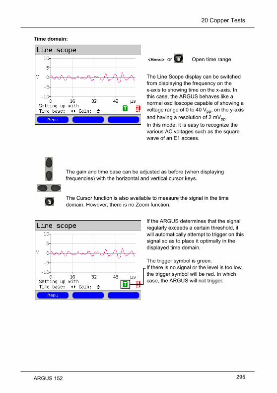
20 Copper Tests
Time domain:
<Menu> or
The Line Scope display can be switched from displaying the frequency on the x-axis to showing time on the x-axis. In this case, the ARGUS behaves like a normal oscilloscope capable of showing a voltage range of 0 to 40 Vpp, on the y-axis
and having a resolution of 2 mVpp. In this mode, it is easy to recognize the various AC voltages such as the square wave of an E1 access.
If the ARGUS determines that the signal regularly exceeds a certain threshold, it will automatically attempt to trigger on this signal so as to place it optimally in the displayed time domain. The trigger symbol is green. If there is no signal or the level is too low, the trigger symbol will be red. In which case, the ARGUS will not trigger.
Open time range
The gain and time base can be adjusted as before (when displaying frequencies) with the horizontal and vertical cursor keys.
The Cursor function is also available to measure the signal in the time domain. However, there is no Zoom function.
295ARGUS 152

20 Copper Tests
Start / Stop:It is always possible to stop or restart a test while the test is running (real-time operation).
Clipping:Time domain:Frequency range:
If the signal on the Line Scope's input is too high or if the gain has been set too high in the frequency or time domain, the Line Scope's input stage will be overdriven.
In this case, the ARGUS will display a clipping symbol .
The displayed signal will be clipped in both the frequency and the time domain. To eliminate clipping, reduce the gain.
The test is running.
Stop test
The test has been stopped.
Start the test again.
296 ARGUS 152

20 Copper Tests
20.4 Active Probe
The ARGUS Active Probe is an active high-impedance probe with which it is possible to passively monitor an existing connection without noticeably disturbing it.
The ARGUS Active Probe II are intended for use with the ARGUS Line Scope function. The high-impedance Line Scope (input impedance 3.6 kcan also be used without the use of the ARGUS Active Probe (see page 294).
20.4.1 Active Probe II
The specifications of the ARGUS Active Probe II are as follows: - Input impedance: 70 k - Input capacitance: < 1 pF - Frequency range: 10 kHz to 30 MHz (±1.5 dB) - Attenuation symmetrical: 14.5 dB - 2 x 4 mm banana jacks (separation 12mm) - Data transferred to ARGUS via an RJ45 cable (pins 4/5) - Supply voltage: 5 V via ARGUS USB host interface and USB cable
The Active Probe II can be operated in "symmetrical" or "asymmetrical" mode. Using the
hotkey it is possible switch between these modes in the menu. Application examples,
see page 294, Line Scope.
Picture of the ARGUS Active Probe II:
Nonetheless, in spite of the probe's high-impedance, it is possible that there may be short interruption in the existing communications connection when the probe is first connected.
297ARGUS 152

20 Copper Tests
20.4.2 Connect the Active Probe II
The Active Probe II is connected to the ARGUS's "Line" jack and its USB-A (Host) interface. The USB host interface of the ARGUS is used to supply the Active Probe with 5 V. The Active Probe is then connected to access under test (this example shows an Active Probe II connected on the line between the modem and DSLAM). The connection should be made using leads as short as possible (< 5 cm).
Connection example:
20.4.3 Start Active Probe II (Line Scope as an example)
After a test has been started (in this example, Line Scope), the Probe menu can be opened from the Graphic functions
or with the key.
Continuation on
next page
The included leads and adapter have been purposely kept short. The leads used with an Active Probe II should be kept as short as possible. In order to attain the best measurement results, it is important that the Active Probe be as close as possible to the line to be measured. Any extension of these cables will increase the input capacitance of the Active Probe and may thus corrupt the measurement results. Even the position of the two cables next to each other may - the greater the distance that they run in parallel to each other - falsify the results. If the Active Probe is used as delivered, the ARGUS will automatically include the resulting additional attenuation when calculating the measurement results.
298 ARGUS 152

20 Copper Tests
Yes
If the Probe is to be used, select the setting "yes".The ARGUS will then switch the supply power onto the USB-A interface and will automatically take the attenuation caused by the insertion of the Active Probe into account when calculating the measurement results.If the Active Probe is activated and if it is properly powered by the ARGUS, the
green LED will light on the probe.
If the Active Probe is correctly connected, a green checkmark will appear in the lower right of the display during the test.If the Active Probe has not been correctly connected and is not recognized by the ARGUS or if it has been deactivated in the Probe menu, an exclamation mark will appear at the lower right of the display instead.
Open the Probe menu directly.
It can take up to 10 seconds for the probe to activate.
299ARGUS 152

20 Copper Tests
Symmetrical/Asymmetrical Switch:For an example of the use of symmetrical / asymmetrical switching, see page 294, Line Scope.Once a test has been started and the
Active Probe II activated, the key
can be used to switch the probe between symmetrical and asymmetrical input.
When the ARGUS is set asymmetrical mode, it will display any interference and noise on the line. The useful signal will be hidden.
300 ARGUS 152

20 Copper Tests
20.5 TDR / Advanced TDR
Using the TDR function, it is possible to determine the line length in realtime and locate sources of interference. Correct interpretation of the pulses displayed by the ARGUS will allow detection of among others stub lines, bad contacts or short-circuits. In performing a TDR, the ARGUS sends a pulse down the connected line and displays the returning reflected pulse.
20.5.1 TDR Settings
ARGUS - Main MenuAccess
Copper Tests
Continuation on
next page
Select Copper TestsARGUS State DisplayAny DC voltage on the line will be displayed.
<Config>
<Menu>
<Start>
Any DC voltage on the access line may not exceed 200 VDC. Furthermore, the line must be free of any AC voltages.
The result displayed of a TDR measurement may create the impression that there are multiple disturbances on the line. It is advisable to clear the first disturbance or fault and then run the test again. It is possible that the first disturbance or fault caused one or more reflections and thus created the false impression that the line has multiple faults. In many cases there is only one fault on the line.
The ARGUS will generate a reflection at about 3 meters. To measure short lines precisely and to avoid this reflection, we recommend the use of longer a connecting cable e.g. one 5 m long.The pulse will still appear in the graph but by using the longer connecting cable you can be sure that it is not from the line under test.
Switch to the wire types list settings.
Open the Main Menu.
Open the Single Tests Menu directly
301ARGUS 152

20 Copper Tests
Select Wire types/VoP.
Select the wire type to be configured.
<Edit>
Change the wire type parameter.
302 ARGUS 152

20 Copper Tests
Speed of propagation
Name
20.5.2 Start TDR
Access
Copper Tests
Continuation on
next page
TDR
ARGUS - Main MenuSelect Copper TestsARGUS State DisplayAny DC voltage on the line will be dis-played.Select and start TDR.
<Config>
<Menu>
<Start>
Setting Explanation
Wire types/VoP
The velocity of propagation factor for the specific type of cable must be
know in order to correctly calculate the length of cable. This velocity of
propagation factor is the ratio between the velocity of propagation of the
pulse in the cable and the velocity of propagation of the pulse in a vacuum
(c0 = 299,792,458 m/μs).
The pulse transit time delay for many wire types is also specified in V/2: Minimum: 45.0 m/μsMaximum: 149.7 m/μsDefault setting: 100.0 m/μsSelect and edit the velocity of propagation as VoP or V/2, and then save it.
Enter the name of the wire type.Default setting: Wire type 1
Switch to the wire types list settings, see page 301.
Open the Main Menu.
Open the Single Tests Menu directly
303ARGUS 152
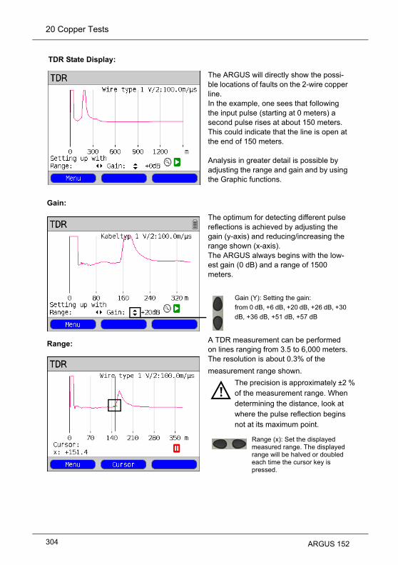
20 Copper Tests
TDR State Display:
Gain:
Range:
The ARGUS will directly show the possi-ble locations of faults on the 2-wire copper line.In the example, one sees that followingthe input pulse (starting at 0 meters) a second pulse rises at about 150 meters. This could indicate that the line is open at the end of 150 meters.Analysis in greater detail is possible by adjusting the range and gain and by using the Graphic functions.The optimum for detecting different pulse reflections is achieved by adjusting the gain (y-axis) and reducing/increasing the range shown (x-axis).The ARGUS always begins with the low-est gain (0 dB) and a range of 1500 meters.
Gain (Y): Setting the gain:from 0 dB, +6 dB, +20 dB, +26 dB, +30
dB, +36 dB, +51 dB, +57 dB
A TDR measurement can be performed on lines ranging from 3.5 to 6,000 meters. The resolution is about 0.3% of the
measurement range shown.
The precision is approximately ±2 % of the measurement range. When determining the distance, look at where the pulse reflection begins not at its maximum point.
Range (x): Set the displayed measured range. The displayed range will be halved or doubled each time the cursor key is pressed.
304 ARGUS 152

20 Copper Tests
f
20.5.3 Graphic functions
The graphic functions like Zoom and Cursor allow detailed analysis of the graphs.
<Menu>
To save the results and quit the TDR function, press the -key in the
State Display (i. e. the display showing the graph).
Zoom:
Continuation on
next page
The Graphic functions menu will open.
The magnifying glass is shown in the display on a white background. The Zoom function is not active in this graph. If the magnifying glass is on a dark back-ground, the graphic is zoomed.<Zoom(x)++>
<Zoom(x)--> Not yet zoomed. Deactivates <Zoom(x)++> and ceases enlargement.
Open the Graphic functions.
Exit menu without making
changes.
Using these numeric keys the
Zoom function can also be acti-
vated within a graph.
The Cursor function is described
on page 306.
Confirms the selection and
returns to the graph.
Enlarges the central section othe graph (100 %)
305ARGUS 152

20 Copper Tests
The Zoom softkeys can be used to zoom in on or out of (the graph) by anywhere from 6.25 % to 100 %. In the process, the resolution will be doubled or halved.By using the Cursor at the same time, it is possible to precisely locate the reflection on the line measured.
The Zoom softkeys can be used to zoom in on or out of (the graph) by anywhere from 1.56 % to 100 %. In the process, the resolution will be doubled or halved.By using the Cursor at the same time, it is possible to precisely locate the reflection on the line measured.Once the Cursor function is started, a green Cursor line will be displayed in the
middle of the graphic.
<Cursor>
The value of the graph at the Cursor's cur-rent position will be displayed below the graph:x:
The Zoom and Cursor functions can also be used in combination. As an example it is eas-ier to measure a specific point in a graph with the Cursor function if you have first zoomed in on the area. The zoomed area will not necessarily be centered on the Cursor.
Switch between softkey sets
Using the Cursor softkey, it is possible to switch the cursor on or off as needed once it has been activated from the menu.
+151.4 m
Using the "left" and "right" cursor keys, the cursor can be moved to any location in the graph to measure it. Briefly tapping the cursor key will move the Cursor one position further in the graph. The Cursor will move in ever larger steps if you press and hold the cursor key down.
Cursor:
If the Stop function (see page 308) is activated, the Cursor can be moved faster.
306 ARGUS 152

20 Copper Tests
Measurement range: The TDR function will be in the State Display in the measurement range when it is first started. In the measurement range, both the range (x) and the gain (y) can be set. If the measurement range has been hidden so as to work with the Cursor or Zoom, it can be redisplayed by pressing:
<Menu>
or
Pulse width:
Using the pulse width setting, it is possible to adjust the shape of the ARGUS's pulse to suit the line being tested.
Width:The pulse width sets the length of the pulse in nanoseconds (ns) that the ARGUS sends down the line. The default pulse width is 452,8 ns; however, depending on the measured range, this value can be increased up to a maximum of 12000 ns (12 μs). Like a higher pulse a longer pulse carries more energy and is therefore mainly of use on longer lines. It must be noted, however, that a longer pulse can also conceal important reflections and thus prevent correct interpretation of the TDR results.
Redisplay measurement range.
Setting the pulse
307ARGUS 152
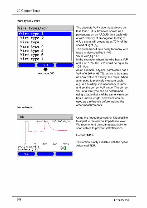
20 Copper Tests
Wire types / VoP:
see page 303
Impedance:
The absolute VoP value must always be less than 1. It is, however, shown as a percentage on an ARGUS. In a cable with a VoP (velocity of propagation factor) of 0.7, a signal will propagate at 70 % of the speed of light (c0). The pulse transit time delay for many wire types is also specified in V/2: V/2 = VoP[%] * 1.5. In the example, where the wire has a VoP of 0.7 or 70 %, the V/2 would be equal to 105 m/µs. As an example, a typical patch cable has a VoP of 0.667 or 66.7%, which is the same as a V/2 value of exactly 100 m/µs. When attempting to precisely measure cable, e.g. in a building, it is necessary to know and set the correct VoP value. The correct VoP of a wire type can be determined using a cable that is of the same wire type, has a known length, and which can be used as a reference before making the other measurements.
Using the impedance setting, it it possible to adjust to the optimal impedance level. We recommend the setting especially for short cables to prevent selfreflections.
Default: 135 Ω
This option is only available with the option Advanced TDR.
308 ARGUS 152

20 Copper Tests
The average value is formed from up to 20 single measurements. Averaging eliminates irregularities caused especially at high gains and disturbed lines. It helps to interpret test results much better.
Start / Stop:
Average value:
It is always possible to stop or restart a test while the test is running (real-time operation).
The test is running.
Stop test.
The test has been stopped.
Start the test again.
309ARGUS 152

20 Copper Tests
20.5.4 Examples
The following ideal waveforms may be of assistance to you in interpreting the reflected pulse:Examples:
Open cableThe reflected pulse is positive. No indication can be seen of adjacent disturbances or the remote end of the line. Short-circuitThe reflected pulse is negative. No indication can be seen of adjacent disturbances or the remote end of the line. MismatchDifferent cross-sections were used in the line. The greater the mismatch, the greater the amplitude of the reflection.Bad junction pointA bad junction between lines produces an "S" shaped reflection. The worse the contact, the greater the reflection.
310 ARGUS 152

20 Copper Tests
Stub line (Bridge Tap)The beginning of a stub line is shown in the form of a negative reflection which is then followed - after a period correspond-ing to the line length to the end of the stub - by a positive reflection if the stub line is open at its end.
Inductance coils / ChokesInductance coils used on the line are opti-mized for the transmission of voice fre-quencies. They block DSL signals. The first such coil on a line can be detected using the TDR function. The reflection in this case will be a positive pulse with a tail trailing off towards the end of the line. Faults after this inductance coil cannot be detected.
Capacitance networkLike a short-circuit, a capacitance network reflects the pulse in a negative form. MoistureIf moisture has gotten into the cable, it will cause a reflection like that of a stub line. The stretch between the negative and the positive reflections will, however, be sub-stantially more noisy than is usually seen from a stub line.
311ARGUS 152

20 Copper Tests
Loose contactReal-time operation is the best approach to locating a loose contact. The amplitude of the positive reflection will vary as the contact is shaken. Open shieldingThe ARGUS can also be used to locate the fault where the shielding of a line is broken or open. In this case, connect one contact of the ARGUS to the "a" and "b" wires and the other contact to the line's shield. The reflection will be like that of an open line.
Correct line terminationIf the line is properly terminated, the entire pulse sent by the ARGUS will absorbed. There will be no visible reflection.
312 ARGUS 152

20 Copper Tests
20.6 Line Qualification
If you want to determine whether a copper wire pair (subscriber's access line) is suitable for DSL, the ARGUS Line qualification (LQ) is the best method for testing the line. To perform this test, an ARGUS with Line qualification is connected to both ends of the line. In this manner it is possible to determine both the quiet level noise and the line's fundamental transfer function. The ARGUS determines the signal-to-noise-ratio (SNR) per carrier frequency and the maximum data rate possible on this subscriber's access line. It is, however, essential that the entire DSL spectrum is analysed. Otherwise, no sound assessment is possible. The advantage of the test is: It always returns an assessment of the data rate – even if a system consisting of a modem (xTU-R) and a DSLAM (xTU-C) cannot be synchronized due to interoperability problems or a line that is too long.
Line
jack
Subscriber's access line
Master Slave
Line
jack
Local loop
ARGUS 1 ARGUS 2
Protocol independent parametersThe settings - determining the conditions under which the Line qualification will record something - can be configured before a test is performed.
313ARGUS 152

20 Copper Tests
20.6.1 LQ settings
Access
Copper Tests
ARGUS - Main MenuSelect Copper tests.
Select the Copper Test to be configured, in this example, Line qualification.
<Menu> Open the Main Menu.
<Start> Open the Single Tests Menu directly.
<Config> Switch to the LQ settings.
314 ARGUS 152

20 Copper Tests
Default settings for- Bandwidth- Bandplan- Impedance Transmit level
<Config> Open the LQ settings.
Setting Explanation
Line qualification
Bandwidth The bandwidth defines the frequency spectrum that will be measured. It
always beginning from 4.3125 kHz. Its width depends on the frequency
range selected.The following frequency ranges can be selected: - 1.1 MHz (ADSL) - 2.2 MHz (ADSL 2+) - 8.8 MHz (VDSL2) - 12.0 MHz (VDSL2) - 17.6 MHz (VDSL2) - 30.0 MHz (VDSL2)Default setting: 2.2 MHz (ADSL 2+)
Edit the marked parameters if
315ARGUS 152

20 Copper Tests
Bandplan The bandplan forms the basis for the assessment of the measurement. The placement and the bandwidth of the upstream and downstream bands, as well as the PSD mask (max. permissible transmitted power per tone), which is required for determining the SNR, all depend on this bandplan.Depending on the bandwidth, the following bandplans are available to choose from:- Annex A (ADSLx)- Annex B (ADSLx)- 998-M2x-A (VDSL2)- 998-M2x-B (VDSL2)- 998ADE17-M2x-A (VDSL2)- 998ADE17-M2x-B (VDSL2)- 998ADE30-M2x-NUS0-A (V)- 998ADE30-M2x-NUS0-M (V)Which bandplan will be required for your particular line depends on the bandwidth and your network operator.Default setting: Annex B (ADSL x)
Impedance The impedance determines how the line must be connected in the device. Ideally, the impedance is chosen to match the characteristic impedance of the line to be measured. It can be set to one of the following: 100 (VDSL2), 120 or 135 .Default setting: 135 (the usual for ADSL)
Transmit level
The transmit level is the level at which the spectrum's tones are transmitted. The default value should only be increased in exceptional cases since doing so will also increase the risk of causing interference with adjacent DSL lines.Default setting: 0 dBm
316 ARGUS 152

20 Copper Tests
20.6.2 Starting Line qualification
ARGUS - Main MenuSelect Copper Tests
Select one of the Copper Tests:- Line qualification
The selected Copper Test will start as soon as it is selected.In this example, Line qualification
<Menu> Open the Main Menu.
<Start> Open the Single Tests Menu directly
Access
Copper Tests
Continuation on
next page
317ARGUS 152

20 Copper Tests
Two ARGUS testers are required in order to run a Line qualification. One ARGUS (ARGUS 1) serves as a Slave (LQ slave mode) and sends the required tones. A second ARGUS (ARGUS 2), receives these tones and displays the measurement results.
Starting Line qualification:ARGUS 1 - LQ slave mode
Sender's specifications:
Frequency range
Output power
Output impedance
ARGUS 1 waits for ARGUS 2 to be ready to receive.
4.3125 kHz to 30 MHz max., Sends from 256 tones (ADSL) to a max. of 4096 tones (VDSL 2).
12 dBm, 6 dBm, 0 dBm switchable
100, 120, 135 switchable
Quit Qualification / Waiting.
318 ARGUS 152

20 Copper Tests
ARGUS 2 - LQ master mode:
Continuation on
next page
Receiver's specifications:
Frequency range
Output power
Output impedance
<Config>
When the sender (ARGUS 1) is found, ARGUS 2 will display its product name (in this example ARGUS 152) and S/N (serial number 8649) and then start the qualifi-cation procedure automatically.
4.3125 kHz to 30 MHz max., Sends from 256 tones (ADSL) to a max. of 4096 tones (VDSL 2).
12 dBm, 6 dBm, 0 dBm switchable
100, 120, 135 switchable
Open the LQ settings.
Quit Qualification / Searching.
Quit qualification
319ARGUS 152

20 Copper Tests
Continuation on
next page
The qualification is running. The attenuation of each tone sent is
measured.
The qualification has ended and the results are displayed (in this example a
three kilometer long line has been tested):
-
-
<Graph>
-
• (Column 2 - SNR [dB])• (Column 3 - QLN [dBm/Hz])• (Column 4 - Hlog [dB])
Depending on the bandwidth selected, this measurement may take up to 1.5 minutes.
DSL-Type/Variant/Annex (Bandplan)
Max. theoretically possible downstream and upstream (d/u) bitrate, which could be attained on this line (attain. data rate) in kbit/s. In this example:
d: 28 740u: 1 620
Open the graphs
For the selected sender frequencies(Column 1 - Freq. [kHz]) value determined:
320 ARGUS 152

20 Copper Tests
Continuation on
next page
Other result graphs
<Graph>
Display the bit distributioni. e. transported bits per tone (channel):y-axis: bits
x-axis: tones (channels)
Display the signal-to-noise-ratio (SNR) per tone:y-axis: SNR in dBx-axis: tones (carrier frequencies)It is possible to detect disturbances on the individual tones (channels).
<Menu>
Display the result graphs
Abort and save
The ARGUS will return to the previous display
<Menu> The Graphic functions like Zoom and Cursor can be performed in the same manner as on an ADSL line, see page 43 and page 106.
<Continue> To scroll to the next graphic.
Opens the graphic functions (see page 43)
321ARGUS 152

20 Copper Tests
Display the quiet level noise (QLN) for each tone. The QLN displays the quiet level noise of the wire pair as function of the frequency:y-axis: QLN in dBm/Hzx-axis: tones (channels)Based on the QLN it is possible to detect narrow-band interference caused by, for example, a medium-wave radio station or a defective switching power supply. Such interference will appear as small peaks.
Display of the amplitude component of the transfer function (HLOG) for each tone. The HLOG shows the attenuation of a line for each frequency.y-axis: Hlog in dBx-axis: tones (channels)
<Menu> Opens the graphic functions (see page 43).
Continuation on
next page
322 ARGUS 152

20 Copper Tests
Save and close the results display.
The ARGUS saves the LQ results in the first available memory location. The memory location can be given any name desired (see page 325).The name for the memory location is entered using the keypad (default: AMP_1, AMP_2.... or the call number of the access under test if the number has been entered into the speed-dialing memory (see page 325).If the memory is full, you must manually select a memory location to be overwritten.
<Graph> Display the result graphs
<No> The results will be discarded.
<Yes> Save results
Save results and return to the State Display
323ARGUS 152

20 Copper Tests
324 ARGUS 152

21 Test Results
21 Test Results
The saved test reports can be viewed either on the ARGUS display or on a PC. The test
data can be sent to a Windows PC, where - using the WINplus or WINanalyse software - it
is possible to generate - among other things - a comprehensive test report.The ARGUS saves the test results together with the date, the time (ARGUS internal clock,
see page 331) and the call number, which is entered in the speed-dialling memory as the
"own number" (see page 336) in one of the 50 sequentially numbered (1, 2, 3, etc.) memory
locations. If no call number is entered under "own number", the ARGUS will suggest
"AMP_x" as a name where the "x" in this case represents the current memory location. If all
the settings are reset, the test results that have been saved will also be deleted. The
functions ("View", "Test data to PC", "Delete") in the Test results menu refer to a test result.
Therefore, a window will open first showing a list of the reports saved.
ARGUS - Main Menu.The ARGUS will display for each memory location the corresponding name of the memory location as well as the date and time. Empty memory locations are labeled as "empty".
<Date> The date and time that the resultswere saved will be displayed.The <Name> softkey will also be displayed.
<Name> Display the name of the memory location.
Test results
ARGUS 152 325

21 Test Results
21.1 Saving Test results
The results of a test can be saved when a test is completed or when a connection is cleared down.The ARGUS saves the test result in the first available memory location. If the memory is full, you must manually select a memory location to be overwritten.As names for the memory locations, the ARGUS will suggest either AMP_1, AMP_2, AMP_3 etc. or the call number entered as the "Own number“ in the speed-dialling memory (see page 336).The name shown can accepted or a new one can be entered using the keypad. When the right softkey is pressed, it assumes a different meaning and thus influences the entries made from the keypad. Up to 24 characters can be entered.
<12>ab> Entry of the digits 0 to 9 plus * and #
<ab>AB> Entry of lowercase characters (e.g. to enter a “c” press the “2” on the keypad three times), plus @, /, -, and .
<AB>12> Entry of the uppercase characters and @, /,- and .
<Delete> Delete the character before the cursor
Move the cursor
Do not save the results;return to the previous display.
Store the result
326 ARGUS 152

21 Test Results
21.2 Displaying the Saved Test Results
ARGUS - Main Menu
21.3 Test Results – Sending to a PC
The test results can be sent to a PC, where they can be visualized and archived. Use the
included USB cable to connect the ARGUS (ARGUS “USB-B” jack) to a USB jack on your
PC and then start WINplus or WINanalyse on your PC.
ARGUS - Main Menu.
Select a memory location(In this example, the first memory location named AMP_1 has been selected).
Select a memory location(In this example, the first memory location named AMP_1 has been selected).All of the test results will be sent.
Test results
1 AMP_1
View
Display the test
report
Test results
1 AMP_1
Test results to PC
Start transfer of test results to PC
ARGUS 152 327

21 Test Results
21.4 Test Results – Deleting
ARGUS - Main Menu
Delete the test report stored in the selected memory location.The memory location will again be marked as "empty".For information on how to delete all test results, see on page 335 “Reset Settings to Factory Settings”.
21.5 Send All Test Results to a PC
The ARGUS sends all of the saved test results to the PC. Connect the ARGUS to your PC
and start WINplus or WINanalyse on the PC.
ARGUS - Main Menu
Select a memory location(In this example, the first memory location named AMP_1 has been selected).
Select one of the stored test reports (in this example, the test results stored in the memory location named AMP_1).
Test results
1 AMP_1
Delete
1 empty
Test results
1 AMP_1
All tests to PC
Start transfer of data to PC
328 ARGUS 152

21 Test Results
21.6 Delete All Test Results
The ARGUS will delete all of the test reports stored in the internal memory.
Select one of the memory locations with stored test results (in this example, the memory location named AMP_1).
Test results
1 AMP_1
Delete all
Press <Yes> to confirm that you
really do want to delete all of the 50
possible test reports.
ARGUS 152 329

22 ARGUS Settings
22 ARGUS Settings
The ARGUS can be configured to suit special requirements. The default (factory) settings
can be restored by selecting "Reset“ (see page 335).
22.1 Trace/remote
The ARGUS passes the recorded data (as an example, in the case of an ISDN access, all
of the D channel messages sent to and received from the network) online directly to the
connected PC.
ARGUS Main MenuThe default (preset) Trace mode will be marked in the display with a .
If the ARGUS cannot send the data to the PC without errors, the “PC” LED will flash at 5Hz
(5 times per sec).
Mark the desired Trace mode The selected Trace mode will be marked blue in the display.
Open the next higher menu without making any changes.
Off Basically, the data will not be sent to the PC.Default setting: off
Auto PC sync. All data will always be sent to the PC (“PC” LED will flash). This setting remains active even after the ARGUS is switched on again.
Manual PC sync. Data will be sent to the PC until the ARGUS is switched off (the "PC" LED will flash). When the ARGUS is switched off and then back on again, Trace mode will be off.
Settings
Trace/remote
The marked Trace mode will be
activated as the default setting.
Off
330 ARGUS 152

22 ARGUS Settings
22.2 Device Settings
The procedure for configuring a device setting will be illustrated with a single example:
"Alarm bell".
ARGUS - Main MenuUsing the cursor keys, select a setting (e.g. Alarm bell).The default setting will be marked in the display with a .
Mark the desired setting. The selected setting will be marked blue in the display.
Open the next higher menu without making any changes to the settings.
Setting Explanation
Menu language
Selection of the menu language.Default setting: depends on country
LCD lightness
Setting the display contrast: The contrast can be changed in 16 steps. The contrast can be increased or decreased using the cursor keys. The display shows a vertical arrow, which shows the current setting on a scale from low to high contrast.
Date / Time
Entry of the date and time (initialisation of the internal clock) via the keypad. Use the vertical cursor keys to scroll from line to line in the display. The entered time will be continuously updated by the ARGUS’s real time clock as long as the power is not interrupted. If the ARGUS switched off without batteries, the clock will still run a few more days on its own internal supply. If the backup supply is exhausted, the time will be undefined and must be set again.
Settings
Device
The marked setting will be
activated as the default setting.
Off
Alarm bell
ARGUS 152 331

22 ARGUS Settings
Ringervolume
With this setting you can set the volume level used by the ARGUS to signal an incoming call.The initial volume level can be set.- Default setting: Level 1 (very quiet)In addition, you can also set the end volume level.- Default setting: Level 7 (very loud)When an incoming call is received, the ARGUS will begin signalling with the initial (very low) volume and increase the volume by one increment each time it signals until it has reached the final (very loud) volume.
Alarm bell The ARGUS signals with an audible alarm in a variety of situations, e.g. when a bit error occurs in a BERT or the ARGUS has synchronized on an xDSL access or when an error counter increments.
When this setting is set to "off“, all audible alarms are suppressed.Default setting: off
Jingle After the tester is switched on and has initialized, it will indicate its readiness by sounding the ARGUS jingle.Default setting: off
Power management
Switch off automatically: Set how long the ARGUS can remain idle before the power management will switch to power down mode if the ARGUS is not connected to the plug-in power supply. If power management is disabled, the ARGUS will display a message, when it is switched on, warning that this will lead to a shorter battery life. This notice can be deactivated by pressing the "X"-key. By pressing <On>, you can reactivate this notice.Default setting: after 5 minutes
Lighting: Sets how long the background lighting will remain on. When operated from the mains power, the background lighting will always remain on. When operating from the battery pack, the ARGUS switch off the background lighting after the set time.Default setting: off after 30 seconds
Software option
Enabling a software option the associated key code must be entered via the keypad. Additional ARGUS options can be enabled if desired by entering the associated 20-place code on the keypad.To obtain this code, please contact us.
short - long Synchronized successfully
long - short Synchronization lost
short - short Error counter incremented (The alarm refers to the last second only. Only one alarm is signalled even if there were several errors.)
332 ARGUS 152

22 ARGUS Settings
22.3 Settings – Backup / Restore
The ARGUS can backup and when needed restore all of its settings (numbers / speed-
dialling memory, PPP user name, PPP password, IP addresses, profile names, user-
specific services, keypad infos, etc.).
Saving settings
ARGUS - Main MenuAll of the ARGUS settings made will be backup and can thus be restored at a later time.
Settings
Backup/Restore
ARGUS 152 333

22 ARGUS Settings
The settings can now be backed up and restored again later should this be needed.
Restoring settingsSelect Restore settings.
The backed up configuration will now be restored.
To backup or restore the settings, you must first enter the safety key.To request the safety key, contact your support (sales partner) or intec directly (see page 11).
Restore the backed up settings.
If no settings have been saved, this function has the same effect as "Resetting to Factory Settings“, see page 335. The saferty key is not required.
Restore now?
<Yes>
and
334 ARGUS 152

22 ARGUS Settings
22.4 Reset Settings to Factory Settings
The ARGUS will reset all settings to the original factory settings.
The speed-dialling memory with the call numbers, PPP user name, PPP password,
IP addresses, profile names, user-specific services, keypad infos and all of the test
results stored in the ARGUS will be deleted.
All settings will be reset to their factory settings.
The ARGUS will immediately display the security warning query "All settings will be reset to the factory settings! All test results will be deleted!Reset now?“
Please contact your support (sales partner) or intec directly for the safety key (see page 11).
Settings
Backup/Restore
The following steps are performed
in the same manner as in "Back up
configuration", see page 333.
and
ARGUS 152 335

22 ARGUS Settings
er
ll
ill
g
22.5 Saving Call Numbers in the Speed-dialling Memory
Ten 24-place call numbers can be entered in the speed-dialling memory.
The first speed-dial number (displayed as "Own number") must be the call number
of the access under test (this is especially important for the automatic Service
check). In the Numbers menu, you can jump from the beginning of the list to the
end by scrolling up.
In the "Remote No. 1-8" memory locations, you can save remote call numbers. In the "X.31
test number" memory location, the ARGUS expects the entry of the X.25 access number
for the X.31 test (see page 235).
ARGUS Main Menu
When entering an own call number with an extension (operation of the ARGUS on
a PBX access), observe the following: The extension is separated from the access
number by a "#". For outgoing calls, the ARGUS uses the entire call number
(without a "#") as the number called (CDPN or DAD) and, for the calling number
(DSS1-CGPN), only the number after the "#", in other words the extension. A "#" at
the beginning of a call number is treated as a valid character.Example: 02351/9070-40 is entered as 023519070#40If the "# " is at the end of a number, when the number is later dialled it will be done
without CGPN or OAD.This is important for some PBXs.
Scroll to the desired location in the speed-dialling memory. Entthe number via the keypad.
<Delete> If the cursor is to the right of thelast character, this character wibe deleted. Otherwise, the character that the cursor is on wbe deleted.
The ARGUS will return to the next higher menu without savinthe number.
Settings
Numbers
The ARGUS
saves the number and returns to
the next higher menu.
Enter the phone number
336 ARGUS 152

23 Using the Battery Pack
23 Using the Battery Pack
Changing the battery pack
Switch the ARGUS off and disconnect the plug-in power supply. Afterwards, loosen the
thumbscrew to release the battery pack.
Battery pack handling
The ARGUS may only be operated with the included battery pack. Connecting any
other voltage supply to the contacts in the device will damage the ARGUS.
Automatic recharging of the battery pack when the ARGUS is switched off
The ARGUS automatically recharges the battery pack, if the ARGUS is connected to the
plug-in power supply and is switched off and the battery pack voltage is too low. While
charging, the ARGUS displays the message “Charge battery”. If you press and hold the
power switch, the ARGUS will switch off before the battery pack is recharged. The ARGUS
remains on after fully recharging the battery pack.
- The supplied battery pack may only be charged in the ARGUS.
- Do not use the supplied battery pack in other devices.
- The ARGUS battery pack may only be actively charged (Charge battery) or trickle
charged (default setting: on) when the ambient temperature is between 0 °C (32 °F)
and +40 °C (104 °F).
- Recharge the battery pack fully at least once a month (even if the ARGUS is not used
for a longer period of time).
- If the lithium-ion battery pack is stored, it should first be charged to between 40 and
60 % of its capacity. If the lithium-ion battery pack is stored for a longer period of time,
it should be recharged to this level every six months.To maximize the service life of a battery pack, if it is to be stored over a longer period
of time, it should not be exposed to temperatures in excess of +50 °C (95 °F).
- Please read the extensive notes on safety and the transport of the lithium-ion battery
pack found in the section "Safety Instructions" (see page 12).
ARGUS 152 337

23 Using the Battery Pack
Charge battery
The ARGUS will display the current charge of the battery pack graphically, if no power
supply is connected. A battery symbol on the display will begin to blink, when there is still
approximately (depending on the mode of operation) 8 minutes reserve. During this period,
it is possible that there may be audible interference and in rare cases even malfunctions.
Connect the power supply.When the plug-in power supply is connected, the battery pack in the ARGUS can be fully
recharged. It is not necessary to manually discharge the lithium-ion accumulators in the
ARGUS battery pack. It may take up to 6 hours to fully recharge the battery pack.
ARGUS Main MenuConnect the power supply!The charging process begins.The ARGUS will display the voltage while charging the battery pack.
Automatic recharging of the battery pack in the background (trickle charge)
ARGUS Main MenuIf the battery voltage is too low, the ARGUS will charge the battery pack automatically in the background when the plug-in power supply is connected (battery symbol shown on the display).
If the ARGUS is disconnected from the power supply before the battery pack is fully
recharged, the ARGUS will not automatically begin to charge the battery pack
again when it is reconnected to the power supply, since the battery voltage is no
longer less than the threshold value.
Charge battery
Charge
Charge batteryU: 4.03V
Charge battery
Auto charge
On
The ARGUS uses
this setting and returns to the next
higher menu.
338 ARGUS 152

24 Firmware Update
24 Firmware Update
You can download a firmware file from www.argus.info/service free-of-charge and save it
on your PC to later transfer to your ARGUS tester.Open the Internet site www.argus.info:Click on "Service" (shown here in blue) in the navigation bar.
This will open the product list:
Select the model of your
ARGUS.
After this page opens, click on "Downloads" in the "Service" column on the left.
ARGUS 152 339

24 Firmware Update
After you have selected the type of device, the page showing the relevant firmware updates
will open. On this page, you can select the firmware variant for your specific country.
After you have selected the required variant, a browser window will open to permit you to
select the location where the firmware should saved on your PC. The remaining steps are
explained in the WINanalyse manual and in the guide for the Update Tool
Important information regarding the ARGUS Firmware Update:
Do not, under any circumstances, start to update the firmware if the ARGUS is
running on its battery pack. First connect the ARGUS to the plug-in power supply,
before sending the firmware update file from your PC to the ARGUS. An ARGUS
USB cable is required to perform an update (USB cable with a mini-USB plug).
Save the configuration and test reports on a PC before beginning an upgrade. Do
not disconnect the ARGUS from the PC during the update. Do not switch the
ARGUS off while an update is being performed. You must also pay attention to the
messages on the ARGUS display – not just the instructions displayed by the
Update Tool on the PC. The update has not been successfully completed until the
Update Tool displays a corresponding message on the PC and the ARGUS – after
being automatically restarted by the Update Tool – shows the normal startup
screen.The ARGUS will not switch on until after you have clicked on one of the two
buttons ("back to step 1" or "Exit program") on the Update Tool after the update
has been completed.
340 ARGUS 152

25 Appendix
25 Appendix
A) Acronyms
Characters
2B1Q 2 Binary 1 Quaternary - line code
3PTY Three Party Service
4B3T 4 Binary 3 Ternary - a Modified Monitored State 43 code (MMS43)
∆f Bandwidth
Ohm (electrical resistance)
A
A Ampere (unit of electrical current)
A3k1H Audio 3.1 kHz
A7kHz Audio 7 kHz
AAL ATM adaptation layer
AC Alternating Current or also an abbreviation for ACcess server
ADSL Asymmetric Digital Subscriber Line
Al Action Indicator
AIT Application Information Table
AMP ARGUS measurement report
ANSI American National Standards Institute
Anx. Annex
AOC Advice of Charge
AOC-D Advice of ChargeCharging information During the call
AOC-E Advice of Charge Charging information at the End of the call
AS Available Second
ASCII American Standard Code for Information Interchange.
ATM Asynchronous Transfer Mode
ATU-R ADSL Transceiver Unit - Remote
Auto-MDI-X Automatic Medium Dependent Interface Crossing
Avg Average
B
BC Bearer Capability
BER 1. Basic Encoding Rules
2. Bit Error Rate
BERT Bit Error Rate Test
BR Bridge
BRAS Broadband Remote Access Server
ARGUS 152 341
25 Appendix
BRI Basic Rate Interface
e.g. Example
C
C Celsius
c0 Speed of light
CALL PROC CALL PROCeeding message
CAT Conditional Access Table
CC Continuity Counter
CCBS Completion of Calls to Busy Subscriber
CCNR Call Complete No Response (Automatic callback if the called party did not answer)
CD Call Deflection
CDN see also CDPN
CDPN CalleD Party Number
CF Call Forwarding
CFB Call Forwarding Busy (call forwarding when busy)
CFNR Call Forwarding No Reply (Call forwarding if no reply)
CFU Call Forwarding Unconditional (Call forwarding permanently)
CGN see also CGPN
CGPN CallinG Party Number
CLIP 1. Calling Line Identification Presentation 2. Clipping
CLIR Calling Line Identification Restriction
CO Central Office
Codec Coder Decoder
COLP Connected Line Identification Presentation
COLR Connected Line Identification Restriction
CONN CONNect Message
CONN ACK CONNect ACKnowledge Message
CQE Conversational Quality Estimated
CR Call Reference
CRC Cyclic Redundancy Check
CT Call Transfer
CUG Closed User Group
CW Call Waiting
D
DAD Destination Address
dB Decibel
dBm/Hz Unit of power referenced to 1 mW (milliwatt) per Hertz
DC Direct Current
DCE Data Communication Equipment
342 ARGUS 152

25 Appendix
DDI Direct Dialling In (dialling in to an extension directly)
DF Delay factor
DHCP Dynamic Host Configuration Protocol
diffserv Differentiated Services
DIN Deutsches Institut für Normung e. V. (the German Institute for
Standardization)
DISC DISConnect Message
DL Download
DMT Discrete Multitone Transmission
DNS Domain Name System
DPBO Downstream Power Back Off
DSCP Differentiated Services
DS Downstream band
DSL Digital Subscriber Line
DSLAM Digital Subscriber Line Access Multiplexer
DSS1 Digital Subscriber Signalling System No. 1
DTE Data terminal equipment
DTMF Dual Tone Multi Frequency
E
EAZ Terminal Ident. No.
ECT Explicit Call Transfer (call forwarding or explicit call diversion)
E-DSS1 European Digital Subscriber Signalling System Number 1
EFS Error Free Seconds
EU European Union
ElektroG Elektro- und Elektronikgerätegesetz (German Electrical and Electronic
Equipment Act)
EMV Electromagnetic Compatibility
EN European Norm
EoA Ethernet over ATM
ES Errored Seconds
ete end-to-end
ETH Ethernet
ETSI European Telecommunications Standards Institute
F
F Farad (unit of capacitance)
Fax G3 Telefax Groups 3
Fax G4 Fax Group 4
FEC Forward Error Correction
FFT Fast Fourier Transform
FS Feature Set
FSK Frequency Shift Keying
ARGUS 152 343

25 Appendix
FTP File Transfer Protocol
FW Firmware
G
GB Gigabyte
Gbit/s Gigabits per second
GBG Closed user group (CUG) (Geschlossene Benutzer Gruppe)
GigE Gigabit Ethernet
H
h hour
HDB3 High Density Bipolar of order 3
HDLC High-Level Data Link Control
HEC Header Error Checksum
HEX Hexadecimal
HLC High Layer Compatibility
HLOG Amplitude component of the transfer function for each tone
HOLD Call Hold
HRX value Hypothetical reference connection
HTTP Hyper-Text Transfer Protocol
Hz Hertz (unit of frequency - 1 cycle per second)
I
i. e. in example
IAD Integrated Access Device
ID Identifier
IEEE Institute of Electrical and Electronics Engineers
IGMP Internet Group Management Protocol
INFO INFOrmation Message
INP Impulse Noise Protection
IP Internet Protocol
IPCP Internet Protocol Control Protocol
IPoA Internet Protocol over ATM
IPoE Internet Protocol over Ethernet
IPTV Internet Protocol Television
ISDN Integrated Services Digital Network
ISO International Standard Organization
ISP Internet Service Provider
ITSP Internet Telephony Service Provider
ITC Independent Transmission Convergence
ITU International Telecommunication Union
K
KB Kilobyte
Kbit/s Kilobits per second
344 ARGUS 152

25 Appendix
L
L1 Layer 1 in the OSI reference model
L2 Layer 2 in the OSI reference model
L3 Layer 3 in the OSI reference model
LAN Local Area Network
LAPD Link Access Procedure for D channels
LCD Liquid Crystal Display
LCN Logical Channel Number (X.25 channel number)
LCP Link Control Protocol
LED Light-Emitting Diode
LL Leased Line (permament circuit)
LLC Low Layer Compatibility
LOS Loss of Synchronization
LOSWS Loss of Sync Word Seconds
LQ Listening Quality
LQO Listening Quality Objective
M
m meter
MAC Media Access Control
MB Megabyte
Mbit/s Megabit per second
MCID Malicious Call Identification
MDF Main Distribution Frame
MDI Media Delivery Index (RFC 4445)
MLR Media Loss Rate
MMS Microsoft Media Server protocol
min. minute
Modem Modulator/Demodulator
MOS Mean Opinion Score
MPEG Moving Picture Experts Group
MTU Maximum Transmission Unit
mVpp millivolt peak-to-peak
N
n/a not available
n/r not received
n/u not used
NAT Network Address Translation
NGN Next Generation Network
NOK Not OK
NP Numbering Plan
NTBA Network Termination for ISDN Basic rate Access
ARGUS 152 345

25 Appendix
O
OAD Origination Address
OAM Operations, Administration and Maintenance
OoS Out of Sequence (OOS)
OSI Open Systems Interconnection
P
PABX Private Automatic Branch Exchange
PADI PPPoE Active Discovery Initiation
PADO PPPoE Active Discovery Offer
PADR PPPoE Active Discovery Request
PADS PPPoE Active Discovery Session confirmation
PADT PPPoE Active Discovery Termination
PAP Password Authentication Protocol
PAT Program Association Table
PC Personal Computer
PCR Program Clock Reference
PD Protocol Discriminator
PDU Protocol Data Unit
PID Packet Identifier
POTS Plain old telephone service (PSTN - public switched telephone network)
P-P Point-to-point
P-MP Point-to-multipoint
PPP Point-to-Point Protocol
PPPoA Point-to-Point Protocol over ATM
PPPoE Point-to-Point Protocol over Ethernet
PPTP Point-to-Point Tunneling Protocol
PSI Program Specific Information
PWR Power
Q
QLN Quiet Line Noise
QoS Quality of service
R
RC Resistance (R) and capacitance (C)
REL RELease Message
REL ACK RELease ACKnowledge Message
REL COMPL RELease COMPLete Message
RFC Request for Comments
RJ Registered Jack (standardized jack)
RoHS Restriction of Hazardous Substances
RT Router
RTCP Real-Time Control Protocol
346 ARGUS 152

25 Appendix
RTP Real-Time Transport Protocol
RTSP Real-Time Streaming Protocol
Rx Receive
S
s second
SBC Session Border Controller - Outbound Proxy
SES Severely Errored Second
SIP Session Initiation Protocol
SNR Signal-to-Noise-Ratio
SNRM Signal-to-Noise-Ratio Margin
Spch Speech
STB Set-Top Box
STUN Session Traversal Utilities for NAT
SUB Sub-addressing (sub-addressing is possible)
SUSP SUSPend Message
T
T Trigger
TCP Transmission Control Protocol
TDR Time Domain Reflectometry
TE TErminal, Terminal Equipment
TEI Terminal Endpoint Identifier
Tel31 Telephony 3.1 kHz
Tel7k Telephony 7 kHz
TM Test Manager
ToN Type of Number
ToS Type of Service
TP Terminal Portability (moving the terminal on the bus)
TS Technical Specification
TTX Teletext
Tx Transmit
U
UDP User Datagram Protocol
U interface BRI U interface (U access)
UL Upload
URI Uniform Resource Identifier
URL Uniform Resource Locator
US VDSL: Upstream band
USB Universal Serial Bus
UUI User-User-Info (UUI),
UUS User-to-User Signalling (transfer of user data)
ARGUS 152 347

25 Appendix
V
V Volt (unit of electrical voltage)
V/2 Pulse transit time delay
VC Virtual Channel
VCC Virtual Channel Connection
VCI Virtual Channel Identifier
VC-MUX Virtual Circuit Multiplexing
VDSL Very High Speed Digital Subscriber Line
ViSyB Video Syntax Based
ViTel Video-Telephony
VLAN Virtual Local Area Network
VL Virtual Line
VLC Video LAN Client
VoD Video on Demand
VoIP Voice over Internet Protocol
VoP Velocity of Propagation (speed with which a pulse travels down a line)
VPI Virtual Path Identifier
Vpp Volt peak-to-peak
VTU-R VDSL Transceiver Unit - Remote
W
WAN Wide Area Network
WEEE Waste Electrical and Electronic Equipment
X
xDSL Collective term for different DSL variants
xTU-C xDSL Transceiver Unit - Central Office
xTU-R xDSL Transceiver Unit - Remote
Z
Z Impedance
348 ARGUS 152

25 Appendix
B) Vendor identification numbers
Abbreviation Manufacturer
ALCB Alcatel (STMicroelectronics)
ANDV Analog Devices
BDCM Broadcom
GSPN Globespan
IKNS Ikanos
IFTN Infineon
META Metanoia
STMI STMicroelectronics
TSTS Texas Instruments
ARGUS 152 349

25 Appendix
C) CAUSE-Messages – DSS1 Protocol
Dec. Cause Description
01 Unallocated (unassigned) number No access under this call number
02 No route to specified transit network Transit network not reachable
03 No route to destination Wrong route or routing error
06 Channel unacceptable B channel for the sending system not acceptable
07 Call awarded and being delivered in
an established channel
Call awarded and connected in an already existing channel
(e.g., X.25 virtual switched connection)
16 Normal call clearing Normal clearing
17 User busy The number called is busy
18 No user responding No terminal equipment answered (Timer NT303 / NT310
time-out)
19 No answer from user (user alerted) Call time too long
21 Call rejected Call rejected (active)
22 Number changed Call number has been changed
26 Non-selected user clearing Incoming call not awarded to this terminal
27 Destination out of order Destination / access out of order
28 Invalid number format (address
incomplete)
Wrong call number format or call number incomplete
29 Facility rejected Requested service is rejected
30 Response to status inquiry Response to status inquiry
31 Normal, unspecified Unspecified for "normal class" (Dummy)
34 No circuit / channel available No circuit / B channel available
38 Network out of order Network not operational
41 Temporary failure Network is temporarily not operational
42 Switching equipment congestion Switching equipment is overloaded
43 Access information discarded Access information could not be transferred
44 Requested circuit / channel not
available
Requested circuit / B channel is not available
47 Resources unavailable, unspecified Unspecified for "resource unavailable class" (Dummy)
49 Quality of service unavailable The requested quality of service is not available
50 Requested facility not subscribed Requested service attribute not subscribed
57 Bearer capability not authorized The requested bearer capability is not enabled
58 Bearer capability not presently
available
The requested bearer capability is not currently available
63 Service or option not available Unspecified for "service unspecified or option not available
class" (Dummy)
65 Bearer capability not implemented Bearer capability is not supported
66 Channel type not implemented Channel type is not supported
69 Requested facility not implemented Requested facility is not supported
70 Only restricted digital information
bearer capability is available
Only limited bearer capability is available
350 ARGUS 152
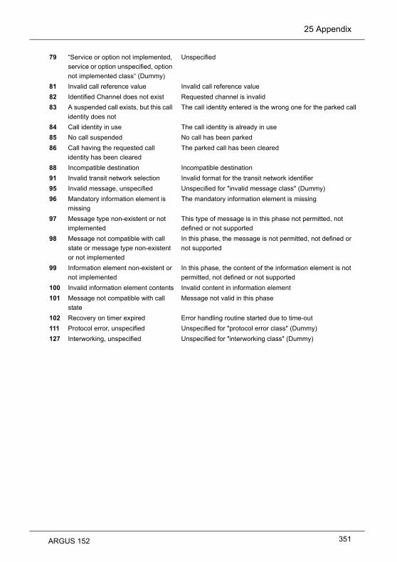
25 Appendix
79 “Service or option not implemented,
service or option unspecified, option
not implemented class“ (Dummy)
Unspecified
81 Invalid call reference value Invalid call reference value
82 Identified Channel does not exist Requested channel is invalid
83 A suspended call exists, but this call
identity does not
The call identity entered is the wrong one for the parked call
84 Call identity in use The call identity is already in use
85 No call suspended No call has been parked
86 Call having the requested call
identity has been cleared
The parked call has been cleared
88 Incompatible destination Incompatible destination
91 Invalid transit network selection Invalid format for the transit network identifier
95 Invalid message, unspecified Unspecified for "invalid message class" (Dummy)
96 Mandatory information element is
missing
The mandatory information element is missing
97 Message type non-existent or not
implemented
This type of message is in this phase not permitted, not
defined or not supported
98 Message not compatible with call
state or message type non-existent
or not implemented
In this phase, the message is not permitted, not defined or
not supported
99 Information element non-existent or
not implemented
In this phase, the content of the information element is not
permitted, not defined or not supported
100 Invalid information element contents Invalid content in information element
101 Message not compatible with call
state
Message not valid in this phase
102 Recovery on timer expired Error handling routine started due to time-out
111 Protocol error, unspecified Unspecified for "protocol error class" (Dummy)
127 Interworking, unspecified Unspecified for "interworking class" (Dummy)
ARGUS 152 351

25 Appendix
D) ARGUS Error Messages (DSS1)
Network The network is not in a state defined for DSS1. This may,
however, occur in connection with normal clearing on a PBX.
Network DSS1 causes
ARGUS An error occurred during the supplementary service test.Frequent cause: no response from network
ARGUS The CF-Test was started with the wrong own number.
ARGUS No HOLD is available, but HOLD is required to test the
supplementary service (ECT, 3pty).
ARGUS CLIR or COLR could not be tested, since CLIP or COLP is not
available
ARGUS The party called did not answer within the prescribed time
(approx.10 sec)
ARGUS A call was setup to a remote subscriber, instead of being setup –
as was expected – to your own number.
ARGUS The Auto-Test could not setup a connection and therefore the
AOC-D supplementary service could not be tested.
ARGUS During the Suppl.services test, a call came in without a B
channel (call waiting). Therefore, it was not possible to accept
the call and test.
ARGUS A call number was entered.
ARGUS Internal error
ARGUS Network did not confirm acceptance of the call (CONN sent, no
CONN_ACK received from network)
ARGUS a) Layer 2 connection has been cleared downb) No response to SETUPc) Layer 2 connection could not be setup
ARGUS Reestablish the Layer 2 connection
ARGUS The selected B channel is already busy.
ARGUS No response to the clear-down (REL sent, no REL_CMP/
REL_ACK received from network)
ARGUS Remote end signaled that it is in State 0.
ARGUS Keypad sent via ESC, but no response was received from
network
ARGUS FACility was sent, but no response was received from network
ERROR Number
Cause Description
0
1 to 127
150
152
153
154
161
162
163
170
199
200
201
204
205
206
210
220
245
250
352 ARGUS 152

25 Appendix
Network See ISO 8208: 1987(E)Table 5- Coding of the clearing cause field in clear indication packets, page 35
ARGUS No answer from network (to a CALL-REQUEST or a CLEAR-REQUEST)
ARGUS Unexpected or wrong answer from network (no CALL-CONNECTED or CLEAR-
INDICATION as answer to CALL-REQUEST)
ARGUS The network has indicated in a DIAGNOSTIC message that the logical channel
is invalid. Origin: No (=1) or a wrong LCN was set.
ARGUS It was not possible to determine an internal or external cause.Origin: Layer 2 could not be setup or remote end does not support X.31
ARGUS The X.31 Layer 3 test was not performed. The error can only occur in a test log.
Network See ISO 8208: 1987(E)Figure 14a page 121Figure 14b page 123 et seq.And/or CCITT Recommendation X.25, Annex E
X.31 Test – Error messages
X.31 Causes
0 to 255
257
258
259
512
65535
X.31 Diagnostic (only for a cause less than 256)
0 to 255
ARGUS 152 353

25 Appendix
E)
Negotiation err
Idle release
Time out rel
PPP: Echo req. error
Hanging up rel
Loopback erro
Authent. Error
PADO timeout
PADS timeout
Error message: PPP connection
ARGUS Display Description
External fault:
Cannot negotiate the network protocol for PPPD, so the remote site is not reachable.
Connection was terminated, since there was no activity.
Connection was terminated, since the maximum connection time elapsed.
Remote site did not answer echo requests so the connection has been terminated. (PPP connections are tested at regular intervals by sending echo requests to the remote site.)
Disconnected by remote site.
The setup of the PPP connection was cancelled, since a loopback was detected.
Authentication error: Wrong user name or password - rejected by remote site.
No PADO packets received.
No PADO packets received.
354 ARGUS 152

25 Appendix
F) Error message: Download test
Http redir.error
http: no response
Http serv.error
Http encod.error
Ftp open error
Ftp login error
Ftp passiv err.
Ftp rec. error
Network error
Ftp error
URL error
Socket error 2
Http Head.error
Ftp no file
Unknown address
Unknown download error
ARGUS Display Description
External fault:
Fault: Too many HTTP redirects.
No answer from HTTP server.
HTTP server has returned an error.(for details see the table below "HTTP Error Messages")
Due to an encoding problem, data transfer with HTTP is not possible.
Error when opening the FTP connection.
FTP login error. Wrong user name or password or anonymous login not supported.
FTP server does not support passive transmission mode.
FTP receive error.
Network error
General FTP error.
Fault: No HTTP or FTP URL specified.
Error when connecting a socket. The server's HTTP service is not available.
Error in the header of the requested HTTP file.
FTP download error: No such file or directory found.
Unknown host address.Possible cause: Error in the address entered, DNS resolution not working or network not accessible.
Unknown download error
ARGUS 152 355

25 Appendix
G) HTTP status codes:
Display on ARGUS:Code No.
Meaning
100 Client should continue its request.
101 The protocol is being changed at the Client's request.
200 The Client's request has succeeded.
201 The Client's request that a new document be created was successful.
202 The Client's request has been accepted for processing.
203 The Client's request will be answered with information from a source other than the server.
204 The Client's request was successful. The server sends [no content] only the HTTP header.
205 The Client's request was successful. The server [resets content] sends a new HTTP body.
206 The Client's request was successful. The server sends only part of the requested document [partial content].
300 The request was not precise enough so multiple documents have been returned.
303 The requested resource has been found at a different URI and should be retrieved from there.
304 The requested document has not been changed in the interim.
305 The requested document must be retrieved from a proxy instead of from the server.
307 The requested resource has been temporarily relocated to a different URI [temporary redirect].
400 Syntax error in the Client's request [Client error].
401 The request requires user authentication.
402 Payment is required to process this request.
403 The Client's request has been refused. (e.g. because authentication failed.)
404 The requested document was not found (e.g. because of an error in the URL entered or while the document is no longer available).
405 The method specified by the Client in its request is not allowed by the server.
406 The requested document in a format that is not supported by the Client.
407 The request requires that the Client authenticate itself with a proxy.
356 ARGUS 152

25 Appendix
408 The Client did not place its request within the time allowed by the server [Request Timeout].
409 Due to a conflict (e.g.another request) the Client's request cannot be completed by the server.
410 The requested URL is [gone] no longer available on the server.
411 The Client sent data to the server without a defined Content Length.
412 The preconditions in the Client's request could not be satisfied by the server.
413 The Client's request has been refused by the server because the request entity is too large.
414 The Client sent a URL to the server that is too large (e.g. because of the form values contained).
415 The Client's data is not supported by the server.
416 The range (in a document) requested by the Client does not exist.
417 The server could not (or did not wish to) satisfy the Client's expectation given in the Expect request header field.
424 Due to a failed dependency, the requested document will not be sent by the server.
500 Due to an unexpected condition, the server cannot fulfill the Client's request (e.g. faulty configuration, missing or wrong CGI program).
501 The server does not support the function required to fulfill the Client's request.
502 The server received an invalid response from an upstream server or proxy which it accessed in attempting to fulfill the request.
503 The server is currently unable to handle the request due to a temporary overloading of the server.
504 The Client's request (of a gateway or proxy) did not receive a response within the specified time.
505 The server does not support the HTTP protocol version that was used in the Client's request.
ARGUS 152 357

25 Appendix
H) General Error Messages
Prot. not supp.
Unknown error
No PPP connec.
Test aborted
Ping start error
Fault: PPP con-nection
Unexp. PING end
Display on ARGUS Description
The protocol (IP, PPPoE, etc.) is not supported in the selected mode.
Unknown error occurred.
No PPP connection can be setup.
Test aborted by user.
Error when starting the Ping test.
Unexpected termination of the PPP connection.
Unexpected termination of the Ping test.
358 ARGUS 152

25 Appendix
I) VoIP SIP status codes
SIP requests:
The six basic requests / methods:
INVITE Invite a user to a session (call - initiates a session)
ACK Acknowledge an INVITE request
BYE Terminate a session (hangup)
CANCEL Terminates the setup of a connection
REGISTER Provides data regarding subscriber availability (host name and IP address)
OPTIONS Supplies information regarding the functions supported by the other SIP telephone
SIP responses:
SIP responses are answers to SIP requests. There are six basic types of SIP responses with numerous sub-responses:
1xx Informational responses (180 indicates for example that the phone of the party called is ringing)
2xx Reports that the request has been successful
3xx Redirection responses
4xx Client failure responses
5xx Server failure responses
6xx Global failure responses
Display on ARGUS: Code No.
Meaning Explanation
100 Trying The ARGUS is attempting to setup a call.
180 Ringing The phone at the other end is ringing.
181 Call Being Forwarded The call is being forwarded.
182 Call Queued The call is in a wait loop.
183 Session Progress The call is being setup.
200 OK Everything is all right.
202 Accepted Connection has been accepted.
ARGUS 152 359

25 Appendix
300 Multiple Choices There is no unique destination address for the remote end. Please select one.
301 Moved Permanently Calls are being permanently forwarded.
302 Moved Temporarily Calls are being temporarily forwarded.
305 Use Proxy A proxy must be used.
380 Alternative Service Alternative service
400 Bad Request The request is not OK.
401 Unauthorized You are not authorized.
402 Payment Required Payment is required.
403 Forbidden This is not permitted.
404 Not Found The remote end was not found or does not exist.
405 Method Not Allowed The method (e.g. SUBSCRIBE or NOTIFY) is not permitted.
406 Not Acceptable The options used in the call are not supported.
407 Proxy Authentication Required The proxy must be authenticated.
408 Request Timeout The time for the request has been exceeded (timeout).
409 Conflict There is a conflict.
410 Gone The subscriber is no longer reachable here.
411 Length Required The length must be supplied.
413 Request Entity Too Large The values are too long.
414 Request URI Too Long The URI is too long. (Destination address)
415 Unsupported Media Type The codec is not supported.
416 Unsupported URI Scheme The URI scheme is not supported. (Destination address)
420 Bad Extension The extension is wrong.
421 Extension Required An extension is necessary.
423 Interval Too Brief There is a problem with the SIP parameters. (Register Expire is too short)
480 Temporarily Unavailable The subscriber is currently not reachable.
481 Call/Transaction Does Not Exist This connection does not exist (any longer).
482 Loop Detected A redirection loop has been detected.
483 Too Many Hops Too many redirects.
484 Address Incomplete The SIP address is incomplete or faulty.
485 Ambiguous The SIP address is not unique.
486 Busy Here The destination is busy.
487 Request Terminated The request has been terminated.
488 Not Acceptable Here The call cannot be accepted.
491 Request Pending A request is waiting.
360 ARGUS 152

25 Appendix
493 Undecipherable Decryption error.
500 Server Internal Error Internal error in the server.
501 Not Implemented The requested method (functionality) has not been implemented.
502 Bad Gateway The gateway is bad.
503 Service Unavailable The service is not available.
504 Server Time-Out The gateway did not respond in time.
505 Version Not Supported The SIP protocol version is not supported.
513 Message Too Large The message length is too long. Use TCP.
600 Busy Everywhere All terminals are busy at the remote end.
603 Declined The system at the remote end refused to accept the call.
604 Does Not Exist Anywhere This user does not exist any longer.
605 Not Acceptable SIP request not acceptable.
ARGUS 152 361

25 Appendix
J) Software Licenses
The ARGUS firmware includes code from what are known as Open Source packages,
which have been published under various licenses (GPL, LGPL, MIT, BSD, etc.). Additional information can be found – if requested in your order – on the CD-ROM included
in the package (see Software_License.htm) or can be viewed at http://www.argus.info/web/download/Software_License.In the event that you are interested in the sources licensed under GPL or LGPL, please
contact [email protected]. A machine-readable copy of the source code can be obtained
from intec Gesellschaft für Informationstechnik mbH for a minimal fee - to cover the cost of
physically copying the code. This offer is valid for 3 years.
362 ARGUS 152
K) Index
AAccess
ADSL .....................................................................................................................31below .....................................................................................................................23BRI ........................................................................................................................23Copper ...................................................................................................................23Ethernet ...........................................................................................................23, 80ISDN ..............................................................................................................23, 211POTS .............................................................................................................23, 275S-Bus ...................................................................................................................213top .........................................................................................................................23U-interface .....................................................................................................23, 213VDSL .....................................................................................................................64xDSL ......................................................................................................................23
Access acceptance report .............................................................................................10Access mode ...............................................................................................19, 21, 23, 28Access parameters ........................................................................................................34Acronyms .....................................................................................................................341Activation delay .............................................................................................................98Active Probe II .............................................................................................................297
Connect the Active Probe II .................................................................................298Connection example ............................................................................................298Start the Active Probe II ......................................................................................298
ADSLAccess mode .............................................................................................31, 39, 62Access parameters ........................................................................................36, 280ADSL .....................................................................................................................36Annex A .................................................................................................................36Annex A auto .........................................................................................................36Annex A/M auto .....................................................................................................36Annex B auto .........................................................................................................36Annex J .................................................................................................................36Annex L .................................................................................................................36Annex M ................................................................................................................36ARGUS-State display ............................................................................................32Bit distribution display ............................................................................................45Bridge ........................................................................................................31, 37, 57Call clearing ...........................................................................................................54Data rate ................................................................................................................43Determination of connection parameters ..............................................................39Display error counters .....................................................................................44, 45Display of Quiet Level Noise .................................................................................50Display the connection parameters .......................................................................43Display the trace data. ...........................................................................................43Displaying the Test Results ...................................................................................56Error Counters .......................................................................................................45Introduction ............................................................................................................31
ARGUS 152 363

Mode ................................................................................................... 35, 36, 41, 43Modem trace display ............................................................................................. 42Profile settings ...................................................................................................... 40Rated Values ........................................................................................................ 36Router ....................................................................................................... 31, 37, 61Save results .......................................................................................................... 54Select the interface ............................................................................................... 32Settings ........................................................................................................... 33, 36Setup the connection ............................................................................................ 40Store result ......................................................................................................... 323Supported Standards ............................................................................................ 17Type of access ...................................................................................................... 31
Alias www address ..................................................................................................... 139AMP ............................................................................................................................ 326Appendix ..................................................................................................................... 341ARGUS
Connections .......................................................................................................... 26Dimensions ........................................................................................................... 16Display dimensions ............................................................................................... 16General Error Messages ..................................................................................... 358Inputs and Outputs ............................................................................................... 16Keypad .................................................................................................................. 16MAC addresses ...................................................................................... 37, 82, 101Settings ....................................................................................................... 330, 331switch on ............................................................................................................... 18Weight ................................................................................................................... 16
ARGUS-State ............................................................................................................. 110ASCII ............................................................................................................................ 99Asymmetrical mode .................................................................................................... 294ATM ........................................................................................................................ 87, 96
Bitrate ................................................................................................................... 52OAM-Ping ........................................................................................................... 120Statistics ............................................................................................................. 101Tests ................................................................................................................... 116with Ethernet ......................................................................................................... 96
Attainable bitrate ..................................................................................................... 52, 72Attenuation .................................................................................................................... 52Audible alarm .............................................................................................................. 332Authentication ............................................................................................................. 162Autonegotiation ................................................................................................. 37, 82, 85
BBackground lighting ...................................................................................................... 16Basic Package ................................................................................................................ 1Battery pack (accumulators) ......................................................................................... 12
Actively charged ..................................................................................... 13, 14, 337Automatically recharging .................................................................................... 337Charger ................................................................................................................. 14Fastener ................................................................................................................ 24Level of charge ................................................................................................... 337
364 ARGUS 152

Long-term storage .........................................................................................14, 337Notes regarding transport ......................................................................................13Protective features ................................................................................................14Storage ................................................................................................................337Swapping .............................................................................................................337Temperature range - charging .................................................................13, 14, 337Transport ...............................................................................................................14Trickle charge ......................................................................................................338Use ......................................................................................................................337
Bits/Tone .........................................................................................................45, 71, 321BRAS statistics ............................................................................................................101Bridge / Router ............................................................................................57, 61, 74, 77
Settings ...............................................................................................57, 61, 74, 77Bridge tap ......................................................................................................................51
HLOG ....................................................................................................................51Rule of thumb ........................................................................................................51
Brief summary .........................................................................................................43, 70Button
Button field ............................................................................................................18
CCable
Patch .................................................................................39, 57, 61, 66, 74, 77, 80xDSL ........................................................................................39, 57, 61, 66, 74, 77
Caller ID .......................................................................................................................163Capacitance measurement ..........................................................................................287Charge battery .................................................................................................13, 14, 337Charging ........................................................................................................................24Checksum error ...........................................................................................................129Codec ..................................................................................................................164, 170Collisions .......................................................................................................................85Continuity error ............................................................................................................205Copper tests ................................................................................................................285Country Code ................................................................................................................53CRC .........................................................................................................................52, 73Cursor function ..............................................................................................................48Cutoff frequency ............................................................................................................69
DData Log ................................................................................................................87, 100Data service ...................................................................................................................89Date .............................................................................................................................325Date / time ...................................................................................................................331Declaration of Conformity ........................................................................................12, 16Del. exist. registrar .......................................................................................................163DHCP ............................................................................................................................98
Auto .......................................................................................................................98Client ...............................................................................................................98, 99Server ............................................................................................................98, 100Timeout .................................................................................................................99
ARGUS 152 365

User Class Information ......................................................................................... 99User-defined Option ............................................................................................ 100Vendor ID .............................................................................................................. 99Vendor Info ........................................................................................................... 99
DIN EN 50419 ............................................................................................................... 13Display backlighting ...................................................................................................... 18Disposal ........................................................................................................................ 13DMT Analysis
Setting ................................................................................................................. 315DNS server ................................................................................................................... 99Download .................................................................................................................... 136
Error Messages .................................................................................................. 355Download filename ..................................................................................................... 138Download rate ..................................................................................................... 141, 146DTMF .......................................................................................................................... 280DTMF settings ............................................................................................................ 165Dual .............................................................................................................................. 98Duplex
Full ........................................................................................................................ 83Half ....................................................................................................................... 83
EElec.length@1MHz ....................................................................................................... 73Electrical length ............................................................................................................ 73Electromagnetic Compatibility ................................................................................ 12, 16ElektroG ........................................................................................................................ 13EN60950-1 .................................................................................................................... 16Encapsulation ............................................................................................................... 96Energy-saving mode ..................................................................................................... 13Enter
............................................................................................................................ 326EoA ............................................................................................................................... 96Error Counters
Reset .................................................................................................................... 53Ethernet
Access parameters ......................................................................................... 81, 82Clearing down ....................................................................................................... 83Flow control .......................................................................................................... 83Mismatch .............................................................................................................. 83Settings ................................................................................................................. 82Setup the connection ............................................................................................ 84Statistics ............................................................................................................... 84Transmission speed .............................................................................................. 23Type of access ...................................................................................................... 80
Ethernet statistics ....................................................................................................... 101
FFEC ......................................................................................................................... 52, 72file size ........................................................................................................................ 138Firewall ................................................................................................................... 61, 77Flow control .................................................................................................................. 83
366 ARGUS 152

Fragmentation .............................................................................................................127FTP download .....................................................................................................106, 143
Results ................................................................................................................147Test parameters ..................................................................................................144
FTP server ...........................................................................................................106, 153FTP upload ..........................................................................................................106, 148
Results ................................................................................................152, 158, 159Test parameters ..................................................................................................149
Functionality ....................................................................................................................1
GGateway IP ....................................................................................................................99Graphic boxes ...............................................................................................................88Graphic functions .........................................................................................................109Grayed out elements .....................................................................................................92
HHandset operation .......................................................................................................169Hazardous goods regulations ........................................................................................14Headset .........................................................................................................................16Headset jack ..................................................................................................................23Headset operation .......................................................................................................169HEC ...............................................................................................................................53Help .............................................................................................................................110Hexadecimal Entry ..................................................................................................36, 82Hide menu items ..............................................................................................................1HLOG/tone ............................................................................................................50, 322Hops ............................................................................................................................132Hotkey Assignment ..............................................................................................108, 110Hotkeys ........................................................................................................................108HRX .............................................................................................................................224HTTP download ...................................................................................................106, 136
parallel .................................................................................................................138Results ................................................................................................................142Test parameters ..................................................................................................138
HTTP status codes ......................................................................................................356Humidity .........................................................................................................................16
IIGMP version ...............................................................................................................195Index ............................................................................................................................363Initial operation ..............................................................................................................24INP ...........................................................................................................................52, 72intec Gesellschaft für Informationstechnik mbH ............................................................11Interleave Delay .......................................................................................................52, 72Internet address .............................................................................................................11Internet Telephony Service Provider ...........................................................................162Interval between carrier frequencies .............................................................................69Introduction ......................................................................................................................7IP ...................................................................................................................96, 333, 335
Local ................................................................................................................37, 99IP ping .................................................................................................................106, 124
ARGUS 152 367

Assigned configuration ....................................................................................... 104Results ................................................................................................................ 129Store result ......................................................................................................... 130Test parameters .................................................................................................. 125
IP statistics .................................................................................................................. 101IP Tests ....................................................................................................................... 124IP version ...................................................................................................................... 98IPoA .............................................................................................................................. 96IPTV ............................................................................................................................ 106
Audio bytes ......................................................................................................... 179CC error .............................................................................................................. 179CC error ratio ...................................................................................................... 179Current RTP loss ratio ........................................................................................ 180Error indication .................................................................................................... 179IGMP latency ...................................................................................................... 179IGMP version ...................................................................................................... 179Jitter buffer .......................................................................................................... 205PCR jitter ............................................................................................................ 179Profile .................................................................................................. 177, 178, 192Profile name ................................................................................................ 180, 205RTP jitter ............................................................................................................. 180RTP sequence error ........................................................................................... 180Scan .................................................................................................................... 192Scan channel selection ....................................................................................... 194Scan max. zapping time ..................................................................................... 196Scan profile ................................................................................................. 192, 196Scan settings ...................................................................................................... 194Server address ................................................................................................... 204Test parameters .................................................................................................. 178Tests ................................................................................................................... 177Thresholds .......................................................................................................... 179Total RTP loss ratio ............................................................................................ 180Type of stream .................................................................................................... 204Video bytes ......................................................................................................... 179VoD ..................................................................................................................... 203
IPTV Line ...................................................................................................................... 89IPTV passive ............................................................................................................... 199IPTV scan ................................................................................................................... 106
Test parameters .................................................................................................. 194IPTV service ................................................................................................................. 89IPv4 ............................................................................................................................... 98IPv6 ............................................................................................................... 98, 104, 125ISDN ........................................................................................................................... 211
Access mode ...................................................................................................... 214Alerting mode ...................................................................................................... 216Anschluss-Modus ............................................................................................... 211ARGUS State display ......................................................................................... 212B channel delay .................................................................................................. 258B channel loop .................................................................................................... 228BERT characteristic values ................................................................................. 225
368 ARGUS 152

BERT HRX value .................................................................................................221BERT results .......................................................................................................224BERT Settings .....................................................................................................221BERT wait ...........................................................................................................227Bit error rate test ..................................................................................................219Bit Error Rate Test on a Leased Line ..................................................................267BRI termination ....................................................................................................217Bus configuration .................................................................................................214Bus status ............................................................................................................214Call acceptance ...................................................................................................218Call Forwarding ...................................................................................................240Call parameters ...................................................................................................217CAUSE Messages .......................................................................................350, 352CF Activation .......................................................................................................242CF Delete ............................................................................................................243CF Interrogation ..................................................................................................240CLIP No Screening ..............................................................................................231Clock mode .........................................................................................................216Connection setup time .........................................................................................257CUG Index ...........................................................................................................218D channel protocol ..............................................................................................214Description of the Supplemental Service ............................................................230Display Advice of Charges (AOC) .......................................................................250DSS1 ...........................................................................................................229, 350DTMF / Keypad ...................................................................................................218Emergency supply ...............................................................................................214En-bloc sending ...................................................................................................251Error Messages ...................................................................................................352Incoming Call .......................................................................................................253Interchannel delay ...............................................................................................259Keypad ................................................................................................................218L1 state ................................................................................................................265Last caller ............................................................................................................252Leased Line .........................................................................................................266Leased Line Loopbox ..........................................................................................269Leased Line Time Measurement .........................................................................270Level and voltage evaluation ...............................................................................214Level measurement .............................................................................................272List of services .....................................................................................................233Managing multiple tests .......................................................................................260Meaning of the LEDs ...........................................................................................213Overlap sending ..................................................................................................249own call number ..................................................................................................250Performing Several Tests Simultaneously ..........................................................244Prefix ...................................................................................................................218Protocol ...............................................................................................................216Redialling .............................................................................................................252Repeat B channel test .........................................................................................212Select the interface ..............................................................................................211Service check ......................................................................................................233
ARGUS 152 369

Service test results ............................................................................................. 234Services .............................................................................................................. 217Settings ............................................................................................................... 216Setup the connection .......................................................................................... 248Supplementary Services Test ............................................................................. 229Supplementary Services Tests - error messages ............................................... 232Supported Standards ............................................................................................ 17TE simulation ...................................................................................................... 213Telephony on a leased line ................................................................................. 266Test Manager ...................................................................................... 111, 228, 260Testing features using the keypad ...................................................................... 256The availability of the B channels ....................................................................... 214Time measurement ............................................................................................. 257Type of access ............................................................................................ 211, 214Voice codec ........................................................................................................ 218X.31 Configuration .............................................................................................. 235X.31 D-channel ................................................................................................... 236X.31 Error Messages .......................................................................................... 353X.31 Test ............................................................................................................ 235
JJingle .......................................................................................................................... 332Jitter buffer .................................................................................................................. 164
KKey ................................................................................................................................ 16
Confirmation ......................................................................................................... 18Cursor ................................................................................................................... 19Level ..................................................................................................................... 19Power .................................................................................................................... 18Return ................................................................................................................... 19Shift ....................................................................................................................... 20Telephone ............................................................................................................. 19
LLAN interface on top ..................................................................................................... 23Latency mode ............................................................................................................... 52Layer 1 .......................................................................................................................... 30Layer 1 box ......................................................................... 30, 43, 59, 67, 69, 75, 78, 90Layer 1 parameters ................................................................................................. 11, 86Layer 2 parameters ................................................................................................. 11, 86Layer 2/3 settings ......................................................................................................... 88Layer 3 parameters ................................................................................................. 11, 86LCD lightness ............................................................................................................. 331LED symbolized .................................................................................... 40, 58, 62, 75, 78LEDs ............................................................................................................................. 18
Ethernet connection .............................................................................................. 23Level key ....................................................................................................................... 19Line attenuation ...................................................................................................... 52, 72Line disturbances .................................................................................................... 45, 71Line jack ........................................................................................................................ 17Line length .................................................................................................................. 288
370 ARGUS 152

Line qualification ..........................................................................................................313Line Scope ...........................................................................................................287, 289
ARGUS State Display .........................................................................................290Clipping ...............................................................................................................296Connection example ............................................................................................290Cursor ..................................................................................................................292Frequency range .................................................................................................291Gain .....................................................................................................................291Graphic functions ................................................................................................292Measurement range ............................................................................................293Start / Stop ..........................................................................................................296Start Line scope ..................................................................................................289Time base ............................................................................................................295Zoom ...................................................................................................................292
Listen port ....................................................................................................................162Lithium ...........................................................................................................................14Long form ..........................................................................................................44, 45, 70Long-term operation ......................................................................................................13Loop
Ethernet connection ............................................................................................114Layer ...................................................................................................................113Layer 1 (L1) .........................................................................................................113Layer 2 (L2) .........................................................................................................113Mode ...................................................................................................................113Protocol independent parameters .......................................................................112Setting .................................................................................................................113Start Loop ............................................................................................................113
Loop attenuation ............................................................................................................72Lowercase .....................................................................................................................97Lowercase characters .................................................................................................126
MMain menu .....................................................................................................27, 212, 276Memory location name ................................................................................................326Menu diagram ................................................................................................................28Menu Hierarchy .......................................................................................................27, 28Menu language ............................................................................................................331Microphone ....................................................................................................................18Mini USB ........................................................................................................................23MOS ....................................................................................................................160, 169MOS threshold .............................................................................................................165MOS Value ..................................................................................................................173Multicast IP ..................................................................................................................178
NNAT .........................................................................................................................61, 77NAT On / Off ..................................................................................................................77Netmask ........................................................................................................................99Network Delay .............................................................................................................173Number key ...................................................................................................................19Numerical keypad ..........................................................................................................19
ARGUS 152 371

OOAM ............................................................................................................................ 120OAM cell type ............................................................................................................. 121Operating temperature .................................................................................................. 16Operation
Example ................................................................................................................ 21Operation - A Brief Guide ..................................................................................... 18
OptionFunction .................................................................................................................. 1Interface .................................................................................................................. 1Software .............................................................................................................. 332
Oscilloscope ............................................................................................................... 295Outbound Proxy .......................................................................................................... 162Output Power .......................................................................................................... 52, 72
Ppacket round-trip delay ............................................................................................... 129PADI ........................................................................................................................... 103PADO .......................................................................................................................... 103PADR .......................................................................................................................... 103PADS .......................................................................................................................... 103PADT .......................................................................................................................... 103PCR jitter .................................................................................................................... 205Phys. parameters .......................................................................................................... 34Pin assignment ............................................................................................................. 23POTS .......................................................................................................................... 275
Access mode ...................................................................................................... 276ARGUS State Display ......................................................................................... 276CLIP .................................................................................................................... 280Dialing mode ....................................................................................................... 280DTMF parameters ............................................................................................... 280FLASH time ........................................................................................................ 281Incoming Call ...................................................................................................... 282Level ................................................................................................................... 280Level measuring ................................................................................................. 284Monitor ................................................................................................................ 283Outgoing Calls .................................................................................................... 282Settings ............................................................................................................... 280Setup the connection .......................................................................................... 282Type of access .................................................................................................... 275
Power management .............................................................................................. 25, 332Power supply ................................................................................................................ 16
Access .................................................................................................................. 23Specifications ........................................................................................................ 12
PPP ............................................................................................. 86, 96, 97, 98, 333, 335Error Messages .................................................................................................. 354Profile .................................................................................................. 86, 88, 93, 97Statistics ............................................................................................................. 101Trace ................................................................................................................... 102
PPPoA .......................................................................................................................... 96
372 ARGUS 152

PPPoE ...........................................................................................................................96PPTP .................................................................................................................80, 96, 98Precision ......................................................................................................................288Print out .........................................................................................................................10Probes .........................................................................................................................132Profile ............................................................................................................................88Profile name ........................................................................................................333, 335Profile types .............................................................................................................88, 89Protective properties ......................................................................................................13Protocol .........................................................................................................................96Protocol statistics .........................................................................................................101Provider Code ................................................................................................................53Pulse dial .....................................................................................................................280PWR ..............................................................................................................................23
QQLN/tone ...............................................................................................................50, 322QoS .............................................................................................................................166Qualify .........................................................................................................................163Quiet level noise (QLN) .........................................................................................50, 322
RR Factor ...............................................................................................................160, 169R measurement ...........................................................................................................285RC measurement ........................................................................................................287
Line loop ......................................................................................................286, 288Open line .............................................................................................................288
Real-time clock ..............................................................................................................25Reg. Expire ..................................................................................................................163Registrar ......................................................................................................................162Relative capacity .....................................................................................................52, 72Remote port .................................................................................................................162Repeat B channel test .................................................................................................213Resistance measurement ............................................................................................287Resync .....................................................................................................................53, 73Return of old equipment ................................................................................................13Rights ..............................................................................................................................2Ringer volume .............................................................................................................332RoHS Compliance .........................................................................................................16RoHS guidelines ............................................................................................................13Router
NAT .......................................................................................................................37SIP port .................................................................................................................38
RTCP ...........................................................................................................................173RTCP statistics ............................................................................................................170RTP .....................................................................................................................160, 173RTP port range ............................................................................................................163RTP statistics ...............................................................................................................169RTSP server type ........................................................................................................205RTSP type ...................................................................................................................205
ARGUS 152 373

SS0/BRI ............................................................................................................ 16, 17, 211Safety Instructions ........................................................................................................ 12
ARGUS ................................................................................................................. 12USB Host interface ............................................................................................... 12
Saving Call Numbers .......................................................................................... 231, 336Saving Test Reports ................................................................................................... 326S-Bus .................................................................................................................. 211, 213Server address ........................................................................................................... 138Server profile .............................................................................................................. 138Service .......................................................................................................................... 13
Start ................................................................................................................ 90, 94Service Statistics ........................................................................................................ 107Services .................................................................................................... 11, 86, 87, 106
Bridge ................................................................................................................... 96Session Border Controller (SBC) ................................................................................ 162Set the IP ...................................................................................................................... 98Showtime ...................................................................................................................... 73Showtime no sync ......................................................................................................... 73Signal attenuation ......................................................................................................... 72Silence detection ........................................................................................................ 163SIP .............................................................................................................................. 160SIP domain ................................................................................................................. 162SIP Log ....................................................................................................................... 173SIP port ......................................................................................................................... 77SNR margin ............................................................................................................ 52, 72SNR/tone .............................................................................................................. 50, 321Softkeys .................................................................................................................. 20, 24
assignment ........................................................................................................... 21Software ........................................................................................................................ 10Software Licenses ...................................................................................................... 362Software updates ............................................................................................................ 8Speaker ........................................................................................................................ 18Speed-dialling memory ....................................................................................... 326, 336Standards ..................................................................................................................... 17Static IP ........................................................................................................................ 98Status screen .................................................................. 30, 33, 67, 84, 86, 87, 106, 110STB ..................................................................................................................... 177, 199Storage temperature ..................................................................................................... 16Stub line
Rule of thumb ............................................................................................... 51, 322Stub line (Bridge Tap) ................................................................................................... 51Support ......................................................................................................................... 11Symbols ........................................................................................................................ 88Symmetrical/Asymmetrical Switch ...................................................................... 294, 300System information in DSLAM ................................................................................ 53, 73
TTDR
Cursor ................................................................................................................. 306
374 ARGUS 152
Examples .............................................................................................................309Gain .....................................................................................................................304Graphic functions ................................................................................................305Measurement range ............................................................................................307Pulse width ..........................................................................................................307Range ..................................................................................................................304Start / Stop ..........................................................................................................308Start TDR ............................................................................................................303TDR - Status display ...........................................................................................304TDR Settings .......................................................................................................301V/2 value .............................................................................................................308VoP ......................................................................................................................303Zoom ...................................................................................................................305
Temperature range - charging .......................................................................................16Test Overview ..............................................................................................................108Test report .....................................................................................................10, 325, 340Test results ..........................................................................................................325, 335Test results - Deleting ..................................................................................................328Test results – Sending to a PC ....................................................................................327Tests ............................................................................................................................106The Active Probe
Connection example ............................................................................................298Start the Active Probe .........................................................................................298
The Physical Layer ............................................................................................11, 30, 86The test results display ................................................................................................327Time .............................................................................................................................325Timeout ................................................................................................................117, 132Timestamp .....................................................................................................................42ToS ..............................................................................................................................166Trace / remote .............................................................................................................330Trace route ..........................................................................................................106, 131
Results ................................................................................................................134Test parameters ..................................................................................................132
Transfer function ....................................................................................................50, 322Trickle charge ............................................................................................13, 14, 27, 337Type of access ......................................................................................................21, 177Type of Service ............................................................................................................166
UU-interface ...........................................................................................................211, 213UN recommendations ....................................................................................................14Update .........................................................................................................................340Update Tool .................................................................................................................340Upload file size ............................................................................................................138Upload filename ...........................................................................................................138Uppercase characters ...........................................................................................97, 126USB
Client interface ................................................................................................16, 23Host interface ..................................................................................................16, 23
User agent ...................................................................................................................163
ARGUS 152 375

User safety .................................................................................................................... 16
VVDSL
Access mode ...................................................................................... 64, 66, 77, 78Access parameters ............................................................................................... 65Bit distribution display ........................................................................................... 71Bridge ....................................................................................................... 64, 66, 74Call clearing .......................................................................................................... 73Carrier Set ............................................................................................................ 65Data rate ............................................................................................................... 69Determination of connection parameters .............................................................. 66Display error counters ........................................................................................... 70Display signal-to-noise ratio .................................................................................. 71Display the connection parameters ...................................................................... 70Display the trace data. .......................................................................................... 70Displaying the Test Results .................................................................................. 73Firmware (FW) ...................................................................................................... 65Graphic functions .................................................................................................. 71Introduction ........................................................................................................... 64Modem trace display ............................................................................................. 68Profile .................................................................................................................... 69Profile settings ...................................................................................................... 67Protocol-dependent settings ................................................................................. 77Rated Values ........................................................................................................ 65Router ............................................................................................................. 64, 77Save result .......................................................................................................... 115Select the interface ............................................................................................... 64Settings ................................................................................................................. 65Setup the connection ............................................................................................ 66Store result ..................................................................................................... 73, 85Supported profiles ................................................................................................. 17Supported Standards ............................................................................................ 17Tests VTU-R ......................................................................................................... 73Type of access ...................................................................................................... 64
Vendor far ............................................................................................................... 53, 73Vendor near ............................................................................................................ 53, 73Version ................................................................................................................ 1, 53, 73Virtual Line .................................................................................................................... 86
Activating .............................................................................................................. 90Settings ................................................................................................................. 96
Virtual Line Settings ...................................................................................................... 96Virtual Lines ...................................................................................................... 11, 86, 87
Examples .............................................................................................................. 95Further .................................................................................................................. 91multiple ............................................................................................................... 181
VL - default configuration .............................................................................................. 89VL Profile .................................................................................................. 11, 86, 88, 106VLAN ...................................................................................................................... 86, 97VLAN handling .............................................................................................................. 66
376 ARGUS 152

VLAN ID ...................................................................................................................66, 97VLAN prioritization .......................................................................................................166VLAN Priority .................................................................................................................97VoD ..............................................................................................................................203
Profile ..........................................................................................................203, 204RTSP ...................................................................................................................204Test parameters ..................................................................................................204
VoD Line ........................................................................................................................89VoD service ...................................................................................................................89Voice codec .........................................................................................................168, 173Voice quality ................................................................................................................168VoIP .............................................................................................................................166
Call acceptance ...................................................................................................175Destination ..........................................................................................................168DS field ................................................................................................................166echo test ..............................................................................................................175MOS Value ..........................................................................................................168Profile name ........................................................................................................165Qos ......................................................................................................................166Register state ......................................................................................................173Results ................................................................................................................172SIP status codes .................................................................................................359STUN server ........................................................................................................165Talk ......................................................................................................................167Test parameters ..................................................................................................162Tests ....................................................................................................................160ToS ......................................................................................................................166Volume ................................................................................................................168
VoIP account ...............................................................................................................161VoIP call ......................................................................................................................106VoIP service ..................................................................................................................89VoIP wait .....................................................................................................106, 172, 174Voltage
DC voltage range ..................................................................................................17VoP ..............................................................................................................................303VPI / VCI ..................................................................................................................86, 96VPI/VCI scan ...............................................................................................................116
Results ................................................................................................................118
WWEEE guidelines ...........................................................................................................13WINanalyse ...........................................................................................................10, 325WINplus .................................................................................................................10, 325Wire types list ..............................................................................................................303
Xx-axis
Frequency .............................................................................................................49Tones ....................................................................................................................49
x-axis labels ...................................................................................................................49x-axis zoom ...........................................................................................................46, 292
ARGUS 152 377

Yy-axis zoom ........................................................................................................... 47, 292
ZZoom ............................................................................................................................. 46
378 ARGUS 152