tmc 225 - rail grinding - transport for nsw · recommended metal removal requirements for wheel...
TRANSCRIPT
Engineering Manual Track
TMC 225
RAIL GRINDING
Version 2.5
Issued April 2013
Owner: Chief Engineer Track
Approved by:
Andrew Wilson Technical Specialist Wheel/Rail
Authorised by:
Malcolm Kerr Chief Engineer Track
Disclaimer
This document was prepared for use on the RailCorp Network only.
RailCorp makes no warranties, express or implied, that compliance with the contents of this document shall be sufficient to ensure safe systems or work or operation. It is the document user’s sole responsibility to ensure that the copy of the document it is viewing is the current version of the document as in use by RailCorp.
RailCorp accepts no liability whatsoever in relation to the use of this document by any party, and RailCorp excludes any liability which arises in any manner by the use of this document.
Copyright
The information in this document is protected by Copyright and no part of this document may be reproduced, altered, stored or transmitted by any person without the prior consent of RailCorp.
En
gin
eeri
ng
Man
ual
UNCONTROLLED WHEN PRINTED Page 1 of 54

RailCorp Engineering Manual — Track Rail Grinding TMC 225
Document control
Version Date Summary of change
1.0 October 2006 First issue as a RailCorp document. Includes content from C 3201, CTN 06/11
2.0 May 2008 C1 - Minor expansion of "Purpose" to include turnouts; C2 - Minor clarifications; C3 - Minor clarifications; C4 Additional definitions; C5-2.1 - Changes to profiles to reflect changes in ESC 220. Explanation of changed templates. Instructions on grinding where defects cannot be removed. C5-3.4 – Change to Track Segment definition. C5-2.1 - Changes to tolerances to reflect changes in ESC 220. Addition of information on transitional grinding. C5-4 – Additional explanation of field side relief. C5-5 – Additional explanation of Vehicle mounted measuring system. C5-8 – Changes to surface finish requirements to reflect changes in ESC 220; C6-4 Addition of information on transitional grinding. C6-5 Explanation of changed templates. C6-7 – Additional information; C7-1and C7-4 – Changed templates and application; C8-2 – Addition of grinding cycle for manganese crossings. C8-2 – Changes and additions to defect explanations; Appendix A - Changes to profiles to reflect changes in ESC 220
2.1 December 2009 Format changes; Title changes to match organisational change; C5-2.1 – minor correction of template name in Note 1 Table 7; C5-6 and C7-6 – inclusion of recommended metal removal requirements for wheel slip damage; C6-7 – inclusion of note regarding extra care required to remove filings in slab track areas; inclusion of reference to TMC 222 for crossing nose profile; C8-4 – inclusion of additional corrective grinding actions
2.2 July 2010 C5-2.1 Addition of explanation of rail profiles
2.3 February 2011 C5-2.1 Table - Modified application of rail profile templates
2.4 April 2012 Reformatted to new template – Page numbering converted to continuous numbering. Separate document control on individual chapters removed; C8-3 - Relaxation of cyclic grinding requirements in turnouts
2.5 April 2013 See Summary of changes below
Summary of changes from previous version
Summary of change Chapter
Control changes Document control
Inclusion of additional reference C1-4.2
Addition of H4 rail profile \; Addition of note regarding application of rail profiles C5-2.1
Changed recommended grinding cycles C8-3
Addition of H4 rail profile Appendix A
© Rail Corporation Page 2 of 54 Issued April 2013 UNCONTROLLED WHEN PRINTED Version 2.5

RailCorp Engineering Manual — TrackRail Grinding TMC 225
Contents Chapter 1 General .............................................................................................................................5
C1-1 Purpose .............................................................................................................................5
C1-2 Context ..............................................................................................................................5
C1-3 How to read the Manual ....................................................................................................5
C1-4 References ........................................................................................................................6
Chapter 2 Management Requirements ...........................................................................................7
Chapter 3 Competencies..................................................................................................................9
C3-1 Plain track grinding............................................................................................................9
C3-2 Turnout grinding ................................................................................................................9
Chapter 4 Common definitions applied in rail grinding..............................................................10
Chapter 5 Plain track grinding.......................................................................................................12
C5-1 Establish grinding locations.............................................................................................12
C5-2 Rail profiles......................................................................................................................12
C5-3 Preparation for grinding...................................................................................................15
C5-4 Application of templates and associated tolerances .......................................................16
C5-5 Vehicle mounted measuring system ...............................................................................19
C5-6 Minimum metal removal for corrective/transitional grinding............................................20
C5-7 Minimum metal removal for preventive grinding .............................................................21
C5-8 Surface finish...................................................................................................................22
C5-9 Monitoring and control.....................................................................................................24
Chapter 6 Rail grinding in turnouts...............................................................................................26
C6-1 Rail profiles......................................................................................................................26
C6-2 Preparation for grinding...................................................................................................26
C6-3 Application of templates and associated tolerances .......................................................26
C6-4 Minimum metal removal for corrective/transitional grinding............................................27
C6-5 Minimum metal removal for preventive grinding .............................................................27
C6-6 Surface finish...................................................................................................................29
C6-7 Grinding operation...........................................................................................................29
C6-8 Monitoring and control.....................................................................................................32
Chapter 7 Guidelines for grinding decisions ...............................................................................34
C7-1 Application of templates ..................................................................................................34
C7-2 Application of the locating lug on low rail and tangent rail templates..............................34
C7-3 Gauge corner relief..........................................................................................................34
C7-4 Field side relief ................................................................................................................34
C7-5 Minimum metal removal for preventive grinding in turnouts ...........................................35
C7-6 Minimum metal removal for corrective grinding ..............................................................35
C7-7 Transitioning the removal of long wavelength corrugations............................................36
Chapter 8 Grinding strategy ..........................................................................................................37
C8-1 General............................................................................................................................37
C8-2 Grinding of new or reoriented rail (mandatory requirements) .........................................37
C8-3 Guidelines for preventive grinding...................................................................................38
C8-4 Corrective grinding ..........................................................................................................39
© Rail Corporation Page 3 of 54Issued April 2013 UNCONTROLLED WHEN PRINTED Version 2.5

RailCorp Engineering Manual — TrackRail Grinding TMC 225
Chapter 9 Template fabrication and calibration ..........................................................................43
C9-1 Template fabrication........................................................................................................43
C9-2 Gauge bar fabrication......................................................................................................43
C9-3 Calibration .......................................................................................................................44
Appendix A Rail Profiles....................................................................................................................46
© Rail Corporation Page 4 of 54Issued April 2013 UNCONTROLLED WHEN PRINTED Version 2.5

1234567
RailCorp Engineering Manual — Track Rail Grinding TMC 225
Chapter 1 General
C1-1 Purpose This manual provides requirements, processes and guidelines for technical specification and management of rail grinding in both mainline track and turnouts.
C1-2 Context The manual is part of RailCorp's engineering standards and procedures publications. More specifically, it is part of the Civil Engineering suite that comprises standards, installation and maintenance manuals and specifications.
Manuals contain requirements, process and guidelines for the management of track assets and for carrying out examination, construction, installation and maintenance activities.
The manual is written for the persons undertaking technical supervision of rail grinding activities.
It also contains management requirements for Civil Maintenance Engineers and Team Managers needing to know what they are required to do to manage rail grinding activities on their area, and production managers needing to know what they are required to do to manage the rail grinding activity.
This manual is part of a series of seven (7) rail manuals
• TMC 22 - Rail Installation & Repair • TMC 2 2 - Rail Welding • TMC 22 - Rail Adjustment • TMC 22 - Rail Defects & Testing • TMC 22 - Rail Grinding • TMC 22 - Rail Defects Handbook • TMC 22 - Surface Defects in Rails
C1-3 How to read the Manual The best way to find information in the manual is to look at the Table of Contents on page 3.
When you read the information, you will not need to refer to RailCorp Engineering standards. Any requirements from standards have been included in the sections of the manual and shown like this:
The following requirements are extracted from RailCorp standard ESC 220.
The rail shapes apply to tangent track and curved track (including for high and low rails) in accordance with Table 1.
Reference is however made to other Manuals.
© Rail Corporation Page 5 of 54 Issued April 2013 UNCONTROLLED WHEN PRINTED Version 2.5

RailCorp Engineering Manual — Track Rail Grinding TMC 225
C1-4 References
C1-4.1 Australian and International Standards
Nil
C1-4.2 RailCorp Documents
ESC 100 – Civil Technical Maintenance Plan
ESC 220 - Rail and Rail Joints
TMC 222 – Rail Welding
TMC 226 – Rail Defects Handbook
© Rail Corporation Page 6 of 54 Issued April 2013 UNCONTROLLED WHEN PRINTED Version 2.5

RailCorp Engineering Manual — Track Rail Grinding TMC 225
Chapter 2 Management Requirements The Civil Maintenance Engineer is responsible for:
1. determining grinding strategies for the District (See Chapter 8),
2. monitoring rail condition through the Track Inspection System, and
3. nominating an Authorised RailCorp Engineer to undertake the activities detailed below.
Note: An Authorised RailCorp Engineer is a RailCorp engineer who has been delegated with engineering authority with respect to Rail Management. This shall be a Civil Maintenance Engineer or a person with appropriate competency delegated by them to undertake rail management activities.
The Authorised RailCorp Engineer shall
For plain track grinding:
1. Undertake visual inspections of the rails at 60 - 70% of the way through the planned grinding period (See Section C5-9.2 Item (2)).
2. Visually assess rail condition before grinding (See Section C5-3.2).
3. Approve application of templates (See Section C7-1).
4. Establish the requirements for removal and replacement of track obstructions that prevent grinding within a section, including high ballast, lubricators and wayside monitoring devices (See Section C5-3.3). It is noted that the period such devices are absent may have an impact on infrastructure and operations.
5. Specify the application requirements for the locating lug on low rail and tangent rail templates (See Section C7-2).
6. Specify Gauge Corner Relief for the high rail template outside the feeler gauge tolerances specified. (See Section C7-3).
7. Specify additional field side relief when, after the application of the normal templates, there is still evidence of field side contact because of excessive tread hollowing on wheels. (See Section C7-4).
8. Specify the metal removal requirements for corrective grinding of transverse profile (See Section C7-5).
9. Specify the requirements for removal of isolated defects identified prior to grinding (such as dipped or peaked welds, wheel burns or squats) (See Section C5-8.2).
10. Authorise variation to the requirement to remove longer pitch corrugations (See Section C7-7).
11. Carry out spot checks of rail grinding on at least 5% to 10% of grinding locations as a follow up to the grinding operation (See Section C5-9.2).
12. Investigate variations to the designed contacts and report major anomalies to the Chief Engineer Track.
For turnout grinding:
1. Visually assess rail condition before grinding (See Section C6-2.2).
© Rail Corporation Page 7 of 54 Issued April 2013 UNCONTROLLED WHEN PRINTED Version 2.5

RailCorp Engineering Manual — Track Rail Grinding TMC 225
2. Approve application of templates (See Section C7-1).
3. Establish the requirements for removal and replacement of track obstructions that prevent grinding of a turnout, including rail lubricators and trackside warning devices, raised checkrails and guardrails (See Section C5-3.3) and for adjustments required at switches including signalling. The period such devices are absent may have an impact on infrastructure and operations.
4. Specify the application requirements for the locating lug on low rail and tangent rail templates (See Section C7-2).
5. Specify additional field side relief when, after the application of the normal template, there is still evidence of field side contact because of excessive tread hollowing on wheels (See Section C7-4).
6. Specify the metal removal requirements for preventive grinding of transverse profile (See Section C7-5).
7. Specify the metal removal requirements for corrective grinding of transverse profile (See Section C7-5).
8. Carry out spot checks of rail grinding on at least 5% to 10% of grinding locations as a follow up to the grinding operation (See Section C6-8.1).
Track Works Manager, Renewals shall:
1. Arrange for the supervision and management of the rail grinder.
2. Supply competent grinding supervisors.
Grinding Supervisors shall
For plain track grinding:
1. Establish the monitoring regime for the grinding operation (See Section C5-3.4 and C5-3.5)
2. Monitor the grinding operation and measure the quality of the output (See Section C5-9.1).
3. Arrange calibration of the templates, gauge bar and other measurement equipment (See Section C9-3).
4. Ensure that the information detailed in Section C5-9.3 has been appropriately collected and recorded.
5. Ensure track obstructions that prevent grinding have been removed (See Section C5-3.3.)
For turnout grinding:
1. Establish the monitoring regime for the grinding operation (See Sections C5-3.4 and C5-3.5).
2. Monitor the grinding operation and measure the quality of the output (See Section C6-8.1).
3. Ensure that the information detailed in Section C6-8.2 has been appropriately collected and recorded.
4. Ensure track obstructions that prevent grinding have been removed (See Section C6-2.3).
© Rail Corporation Page 8 of 54 Issued April 2013 UNCONTROLLED WHEN PRINTED Version 2.5

RailCorp Engineering Manual — Track Rail Grinding TMC 225
Chapter 3 Competencies
C3-1 Plain track grinding
C3-1.1 Grinding Supervision
The grinding supervision must be undertaken by personnel who have the following demonstrated competencies:
• Competent in the use of rail condition and rail grinding terminology. • Competent in the use of rail grinding for rail profiling and defect correction. • Competent in the inspection of rail surface condition and identification of common
defect conditions (as discussed in Chapter 7). • Competent in the inspection of contact bands on rail arising from wheel contacts. • Competent in the assessment of completed rail grinding work. • Competent in reading and writing and the compilation of detailed records as
specified in this manual. • Experienced in the operation of rail grinding and rail condition assessment for not
less than three months (this can be under the supervision of more experienced personnel).
Both grinding supervisors and grinding personnel (including any contractor personnel) shall undergo a suitable training course to obtain appropriate accreditation.
C3-1.2 Authorised RailCorp Engineer
An Authorised RailCorp Engineer must have undergone a training course in rail management and have demonstrated competency in the assessment of rail conditions and suitable remedial measures as outlined in this manual.
C3-2 Turnout grinding
C3-2.1 Grinding Supervision
The requirements are as contained in Section C3-1.1 but with the addition that grinding supervisors must be competent in the specific requirements of grinding turnouts and must be experienced in the operation of rail grinding and rail condition assessment at turnouts for not less than three month (this can be under the supervision of more experienced personnel).
Both grinding supervisors and grinding personnel nominated by the contractor shall undergo a suitable training course that includes consideration of grinding at turnouts to obtain appropriate accreditation.
C3-2.2 Authorised RailCorp Engineer
See Section C3-1.2
© Rail Corporation Page 9 of 54 Issued April 2013 UNCONTROLLED WHEN PRINTED Version 2.5

RailCorp Engineering Manual — Track Rail Grinding TMC 225
Chapter 4 Common definitions applied in rail grinding
Running Surface:
Gauge Corner:
Gauge CornerRegion:
Field Side Region:
Gauge Face:
Field Side:
Gauge CornerRelief:
Field Side Relief:
Contact Band:
Gauge Bar:
Rail Grinding Template:
Cant Bar:
The zone on top of the rail head which makes contact with the wheel tread (refer to Figure 1).
C/L
Running Surface Region
40 mm
Field Side
Gauge Face
Figure 1 - Regions in 60 Kg/m Rail
Field SideRegion
Gauge Corner Region
Gauge Corner
45º
The top corner of the rail above the gauge face (refer to Figure 1).
The zone on top of the rail head between the running surface and the gauge face (refer to Figure 1).
The zone on top of the rail head between the running surface and the field face (refer to Figure 1).
The zone of the rail head facing the inside of the track. In the tighter curves the gauge face may be worn due to contact with the wheel flange (refer to Figure 1).
The side of the rail opposite the gauge face (refer to Figure 1).
Clearance between the wheel profile and the rail profile to reduce wheel rail contact in the gauge corner region (refer to Figure 1).
Clearance between the wheel profile and the rail profile to reduce wheel rail contact on the head of the rail on the far field side (refer to Figure 1).
The actual contact position of the wheels on the rail as evidenced by the shiny worn surface. This generally applies to contact occurring on the running surface of the rail.
A rod or bar section which sits between and normal to the rails to provide a superelevated reference for the application of the template.
A template used to fit over the head of the rail to show the relationship of the ground rail to the defined rail profile.
A flat bar section that sits over the rails to provide a measure of the actual rail cant when taking rail profiles.
© Rail Corporation Page 10 of 54 Issued April 2013 UNCONTROLLED WHEN PRINTED Version 2.5

RailCorp Engineering Manual — Track Rail Grinding TMC 225
Checking Locations: Specific points marked on the rail where the achievement of the defined rail profile and/or metal removal is checked and monitored.
Track Segment A section of track in which the rail is ground to a uniform profile, for example: a curve from the start TP to the end TP, or a tangent from the start TP to the end TP, or the mid point of a short (< 200m) tangent separating two curves.
Preventive or Cyclic Grinding
Grinding carried out to a regular schedule for the purpose of maintaining the rail profiles, preventing or inhibiting the growth of defects, and maintaining the surface condition of the rail (particularly in terms of corrugations and local vertical irregularities), with a minimum metal removal of 0.2 mm from the rail contact surface each grinding cycle.
Transitional Grinding
Grinding carried out usually over several cycles to transfer from a corrective/defect to a preventive/cyclic grinding regime.
Corrective or Defect Grinding
Grinding to remove specific defects in the rail. Such defects may occur over a relatively long track section (for example: rail corrugations or extensive rolling contact fatigue) or over relatively short track sections (for example: wheelburns, squats or isolated rolling contact fatigue defects).
New Rail Grinding: Grinding to profile of rails that have been in track for less than 5 Million Gross Tonnes (MGT).
Previously Ground Rail Grinding:
Grinding of rail to profile which has been profile ground previously but is beyond the specified cycle, noting that the actual rail grinding effort in this case will depend on the tonnage level beyond the specified cycles which the rails have experienced, i.e. more grinding effort will be required as the tonnage beyond the specified limits increases.
Vehicle Mounted Measuring System
A system mounted on the rail grinding unit or auxiliary vehicle that is capable of measuring the rail head profiles, metal removal and/or surface characteristics.
© Rail Corporation Page 11 of 54 Issued April 2013 UNCONTROLLED WHEN PRINTED Version 2.5
RailCorp Engineering Manual — Track Rail Grinding TMC 225
Chapter 5 Plain track grinding
C5-1 Establish grinding locations Establish the grinding cycle requirements for track sections in accordance with the strategy detailed in Chapter 8 and the profiles to adopted (detailed in Section C5-2 with the following additional guidelines:
1. Some curves or track sections have multiple radii. In these cases, to avoid the need to cover the curve or track section at different cycles and to ensure a continuous rail profile, grind the full curve or track section at the cycle associated with the smallest radius that makes up at least 20% of the total curve length or track section.
2. A limited number of track sections may also require special consideration in relation to the grinding cycles and profiles to be adopted. For example: When two curved track sections are joined by a relatively short (less than 200m) tangent section. In these cases, the short middle segment may be treated the same as the adjoining longer curve segments. On the other hand, if short curved sections (less than 80m) are separated by tangent sections, they may also be treated the same as the adjoining longer tangent segments.
3. Each curve MUST be fully ground between the tangent points (TPs) defining that section, as indicated in the appropriate Track Geometry Data Sheets. It is not permissible to grind only a portion of a curve.
C5-2 Rail profiles
C5-2.1 Rail Profiles and associated templates
The rail shapes required have been determined for tangent track and curved track (including for high and low rails).
They are as indicated in the following requirements extracted from RailCorp standard ESC 220.
The rail profiles to be achieved by rail grinding shall meet the following requirements:
• The rail shapes apply to tangent track and curved track (including for high and low rails) in accordance with Table 1.
• The same basic shapes apply to 53 kg/m, 60 kg/m and 60kg/m head hardened rail.
• The rail profiles apply to preventive and defect grinding.
• The rail profiles and their associated templates to be used are summarised in Table 1. The details of each template design are given in Appendix A.
© Rail Corporation Page 12 of 54 Issued April 2013 UNCONTROLLED WHEN PRINTED Version 2.5

RailCorp Engineering Manual — Track Rail Grinding TMC 225
Situation Profile Name Template
Modified MT Tangent
Tangent track and curves with radius ≥ 800 m
Curved track (< 450m radius), mainly passenger RPH2000 H1traffic, high rail (53 kg/m and 60 kg/m rails)
Curved track (< 1000m radius), mainly passenger Modified Low ML1traffic, low rail (53 kg/m and 60 kg/m rails) Rail
Passenger
Curved track (< 450m radius), mainly freight or coal RMH2000 H2traffic, high rail (53 kg/m and 60 kg/m rails)
Curved track (< 1000m radius), mainly freight or Revised Low RL2coal traffic, low rail (53 kg/m and 60 kg/m rails) Rail Freight
H3 H3transitional (53 kg/m and 60 kg/m rails)Curved track (≥ 450m and < 800 m radius), high rail
Rail in turnouts Modified MT Tangent
For use in locations which are vulnerable to rail H4 H4squats
Note: The application of the MT, H1, H2 and H3 profiles above account for thebalance between rail gauge face/wheel flange wear and potential RCF/squatdevelopment
Note: This standard provides current practice for the rail profiles to use on various configurations. These may vary subject to development and experience. Adjustments to the application of profiles may be made by the Chief Engineer Track who will provide direction to grinding staff.
Table 1 - Rail Profiles
The rail shapes are designed to suit the wheel profiles and the rolling stock using the track. As part of the design the contact band width and location position is determined.
The profiles provide improved wheel/rail contact characteristics and contact band widths, as follows:
• For passenger traffic - central contact on low and tangent rails with a contact band width of 18-30mm, and conformal gauge corner contact on the high rails of sharper curves extending 0 to 10mm from the centre line towards the field side.
• For mixed passenger/freight traffic - central contact on low and tangent rails with a contact band width of 25-35mm (which depends mainly on the levels of tread hollowing present on freight wheels), and conformal gauge corner contact on high rails of sharper curves extending 5 -15mm from the centre line towards the field side.
The designed rail shapes required have been converted into matching templates for use with the rail grinding operation.
The templates to be used are detailed in Table 1.
Figure 2 provides an illustration of the modified profiles in relation to a new 60kg rail. It should be noted that the high rail templates (H1, H2 and H3) contain a run-off section that is not part of the design profile (refer to Figure 2 and Appendix A.)
© Rail Corporation Page 13 of 54 Issued April 2013 UNCONTROLLED WHEN PRINTED Version 2.5

RailCorp Engineering Manual — Track Rail Grinding TMC 225
High Rail, H1
High Rail, H2
Low Rail, ML1
Low Rail, RL2
Tangent Rail, MT
High Rail, H3
Figure 2 - New and Modified 60 Kg Rail Profiles
From Figure 2 the following main variations are evident:
• In the new high rails the H1 profile requires minimal metal removal. The H2 profile exhibits a minor undercut in the gauge corner region relative to the new rail, with the aim of reducing the contact stresses in this region. Hence, the gauge corner of H1 is slightly prouder than that of H2, with the aim of improving the steering characteristics of passenger vehicles and thus reducing wheel flange wear.
• The H3 profile, which is applied only when the high rails exhibit severe or very severe gauge corner RCF defects, exhibits an additional undercut in the gauge corner region, with the aim of minimising contacts in this region as part of a transitional grinding strategy.
• In the low rails both the ML1 and RL2 profiles have similar gauge corner region details, which exhibit very minor undercuts relative to the new rails, with the aim of centralising the wheel/rail contact on the running surface. However, RL2 has more field side relief than ML1, to prevent contact in this region with the more hollow wheels present in freight and coal traffic
• In the tangent rail, the MT profile exhibits an even greater undercut in the gauge corner region, to ensure that wheel/rail contact is made near the centre of the running surface, which enhances vehicle stability at higher operating speeds.
However, it should be noted that in worn rails or rails that are outside the specified grinding cycles the metal removal requirements could be considerably greater.
In certain cases, there may be a requirement to apply corrective/defect grinding, which will entail the removal of a considerable amount of metal primarily from the running surface of the rail along a certain length of track. In all of these cases, complete the grinding by implementing the relevant rail profiles as specified in Table 1, which shall conform with all of the standards applied to the normal preventive grinding practice. The only allowable exception is when the rail profiles before grinding are significantly different to the required profiles, due to excessive gauge corner and/or field side relief applied during previous grinding cycles. In these cases, the rails can be treated as transitional and a relaxation of the required tolerances outside the contact band may be applied at the discretion of the Authorised RailCorp Engineer.
© Rail Corporation Page 14 of 54 Issued April 2013 UNCONTROLLED WHEN PRINTED Version 2.5

RailCorp Engineering Manual — Track Rail Grinding TMC 225
The templates used for tangent and low rails contain positioning lugs and these should be used for tangent and low rail templates as illustrated schematically in Figure 3. The purpose of this lug is to provide a referencing point for the template relative to the centreline of the rail. The application of the positioning lug is detailed in Section C5-4. It should be noted that due to rail manufacturing tolerances the locating lug may not make contact on the gauge face even in new rails
16 mm
Template
Positioning Lug
GC
Figure 3 - Schematic illustration of template and positioning lug
C5-3 Preparation for grinding
C5-3.1 Track geometry
Grinding should be conducted on track that has good top and line, preferably after the track has been surfaced.
C5-3.2 Rail condition assessment
Visually assess rail condition before grinding.
This assessment will assist in determining the maintainer specified requirements for the grinding operation.
C5-3.3 Remove track obstructions
Remove all track obstructions that prevent grinding within a section (including high ballast, lubricators and wayside monitoring devices) prior to grinding and replace them after grinding in accordance with the requirements specified by the Authorised RailCorp Engineer.
C5-3.4 Establish grinding segments
Divide the track into segments as follows:
1. Each segment should have a consistent rail surface shape and condition.
2. A segment cannot be longer than a whole curve, although individual curves can be broken up if required.
3. Adjoining curves with a small tangent in between can be ground as two curves (as detailed in Section C5-1).
© Rail Corporation Page 15 of 54 Issued April 2013 UNCONTROLLED WHEN PRINTED Version 2.5

RailCorp Engineering Manual — Track Rail Grinding TMC 225
4. A track segment should generally be no longer than 500m in curved track with radii up to 1000m, and 1000m in tangent track and shallower curves, or no longer than 300m in the case of corrective/defect grinding.
C5-3.5 Establish checking locations
1. Each grinding segment is assessed separately.
2. Nominate a set location in each segment as a checking location that will be used for checking the ongoing grinding program.
3. Position the checking location towards the centre of the segment to be ground, avoiding closures or anomalous profile conditions.
4. Paint-mark the rail web and foot and record its location.
C5-4 Application of templates and associated tolerances
C5-4.1 Placement
1. Attach the rail template to the gauge bar.
2. With the non-template end of the gauge bar resting on the other rail, place the template onto the rail to be checked and move it down and across to maximise the contact of the template on to the rail. Where the template is provided with a gauge positioning lug, push the lug up against the gauge face of the rail. (for further details refer to C5-4.2)
Note: DO NOT use excessive force on the template or gauge bar. This may lead to distortion or accelerated wear.
C5-4.2 Tolerance to template
The rail is to be ground so that the profile matches the template within the following allowable tolerances extracted from RailCorp standard ESC 220.
The maximum allowable gaps between rail profile and template shall be as follows:
0.20 mm (i.e. a 0.25 mm feeler gauge must not pass between the template and the ground rail head covered by the template) within the contact bands (minimum and maximum) on the contact band of any template. This includes the gauge corner area in the case of the high rail template.
0.40mm (i.e. a 0.45mm feeler gauge must not pass between the template and the ground rail head covered by the template) in the gauge corner and field side (up to 5mm from the field side corner) regions outside the contact bands (minimum and maximum) where low and tangent rail templates have been used, and the field side region where the high rail templates have been used.
The application of these tolerances is illustrated schematically in Figure 4.
© Rail Corporation Page 16 of 54 Issued April 2013 UNCONTROLLED WHEN PRINTED Version 2.5

RailCorp Engineering Manual — Track Rail Grinding TMC 225
High Rails in Sharp Curves Low, Tangent and High Rails in Shallow Curves
Max Deviation < 0.25mm
Contact Band Contact Band
Max Deviation < 0.45mm
Max Deviation < 0.25mm
Max Deviations < 0.45mm
Figure 4 - Schematic illustration of rail tolerances and templates
When applying mechanical means, check the tolerance to template by measuring the visible gap between the rail and the template using a feeler gauge 3mm wide at the end.
To provide appropriate referencing for the above measurements, the rail templates should contain scribe marks indicating the position of the contact bands and the contact angles.
When the rail profiles before grinding are significantly different to the required profiles, due to excessive gauge corner and/or field side relief applied during previous grinding cycles (refer to C5-3.3) or in new 60 kg/m rails (refer to Figure 2), the rails can be treated as being in a transitional regime. To reduce the number of grinding passes that may be required to establish the most appropriate profiles, as summarised in Table 1, a relaxation of the required tolerances outside the contact band may be applied at the discretion of the Authorised RailCorp Engineer, as follows:
1. The grinding applied during each cycle must reduce the maximum deviation of the rail profile relative to the template outside the contact band by at least 0.3mm.
2. Within the contact band the tolerances shall remain as specified above.
3. A minimum metal removal of 0.2mm shall still be achieved within the contact band, as specified in Section C5-7).
In such cases, the Contractor shall record the fact that the rails before grinding did exhibit excessive gauge corner and/or field side relief and that a transitional grinding strategy has been applied.
Some rails may exhibit plastic flow lips, which may increase the difficulty of matching the templates with locating lugs.
DO NOT use high rail templates with the lug.
The Authorised RailCorp Engineer will specify the requirements for application of the positioning lugs for the low rail and tangent rail templates, subject to the following:
• If the lug is more than 2 mm away from the gauge face of the original rail, the distance must be reduced to less than 2 mm after grinding. This may require additional grinding passes or the establishment of a transitional grinding strategy, at the discretion of the Authorised RailCorp Engineer.
• The distance of the lug from the gauge face after grinding must be no greater than the distance before grinding.
© Rail Corporation Page 17 of 54 Issued April 2013 UNCONTROLLED WHEN PRINTED Version 2.5

RailCorp Engineering Manual — Track Rail Grinding TMC 225
For example: Figure 5 illustrates rails in tangent track before and after grinding with the templates containing the locating lug.
Before Grinding
Down Rail
Up Rail
0.9 mm Gap
1.2 mm Gap
0.3 mm Gap
0.7 mm Gap
After Grinding
Before Grinding
After Grinding
Excessive Field Side Relief
Excessive Field Side Relief
Figure 5 - Rails in tangent track before and after grinding and tangent templates with positioning lug
C5-4.3 Gauge Corner Relief
Gauge corner relief is built into the rail templates.
Where severe RCF gauge corner damage is occurring the H3 template shall be applied inaccordance with Section C5-4.
The grinding facet limits as specified in Section C5-8.1 must still be observed.
Gauge corner undercutting leads to two point wheel/rail contact conditions in the sharpercurves as illustrated in Figure 6, which in most cases is not desired.
C5-4.4 Field Side Relief
Generally any required field side relief is built into the templates.
The Authorised RailCorp Engineer may specify relief requirements but only up to the tolerances specified in Section C5-4.2.
Excessive field side undercutting, as illustrated in Figure 7, leads to a narrowing of the wheel/rail contact band.
© Rail Corporation Page 18 of 54 Issued April 2013 UNCONTROLLED WHEN PRINTED Version 2.5

RailCorp Engineering Manual — Track Rail Grinding TMC 225
Figure 6 - Example of unacceptable gauge corner undercutting on high rail in sharp curve (arrow points to gauge corner)
Figure 7 - Example of unacceptable excessive field side relief in tangent rail
C5-5 Vehicle mounted measuring system A vehicle mounted procedure for monitoring rail profiles before/during/after grinding, based on optical measuring systems, may be utilised to facilitate the grinding process.
All of the tolerances specified for the manual measurement system, as specified in Section C5-4, shall apply to the vehicle mounted measurement system.
The measuring system must have a proven accuracy and repeatability of better than ± 0.10mm vertically when comparing actual rail to the target template.
Initially, the vehicle mounted system shall be used in a manner similar to the manual measurements, i.e. at the specific checking locations, each representing a track segment.
Eventually it is envisaged that additional and more detailed rail profile measurements after grinding will be taken using the vehicle mounted system on at least one track segment ground in each grinding shift (or day).
© Rail Corporation Page 19 of 54 Issued April 2013 UNCONTROLLED WHEN PRINTED Version 2.5
RailCorp Engineering Manual — Track Rail Grinding TMC 225
The measurements will be taken at 20-25m intervals along the track segment. The profile deviation values will then be used to determine and meet the following maximum allowable deviations from the respective templates:
Within the contact zones (refer to Figure 4):
• 90% of values must be less than 0.25mm • 95% of values must be less than 0.30mm • 98% of values must be less than 0.35mm
Outside the contact zones (refer to Figure 4):
• 90% of values must be less than 0.45mm • 95% of values must be less than 0.50mm • 98% of values must be less than 0.55mm
Alternatively, no more than one (1) measurement location in the track segment is permitted to be outside the limits.
The vehicle mounted systems shall achieve compliance to template at least equivalent to the manual methods previously described.
In addition, metal removal across the rail head and the total metal removal shall also be measured. This will require rail profile measurements to be taken both before and after grinding.
C5-6 Minimum metal removal for corrective/transitional grinding The Authorised RailCorp Engineer will specify the metal removal requirements for corrective grinding of transverse profile.
This may allow some gauge corner cracking/ checking to remain in track after grinding as shown in Figure 8 below.
As indicated previously, notwithstanding the metal removal requirements, the recommended rail profiles shall always be achieved. Thus, in the case of high rails exhibiting gauge corner RCF defects up to a moderate classification (refer to Engineering Manual TMC 226 - Rail Defects Handbook) the H1 or H2 templates shall be applied to the high rails, while for severe gauge corner RCF defects the H3 template shall be applied.
Where wheel slip damage, including surface skidding, is present, it should be treated by grinding a minimum of 0.5mm from the rail surface. Guidelines for corrective grinding of rail defects are provided in Section C8-4.
© Rail Corporation Page 20 of 54 Issued April 2013 UNCONTROLLED WHEN PRINTED Version 2.5

RailCorp Engineering Manual — Track Rail Grinding TMC 225
Figure 8 - Example of Gauge Corner Checking Defects Left in the Rails After Grinding (Arrow Points to the Gauge Corner)
C5-7 Minimum metal removal for preventive grinding Note: this includes initial grinding of new rail.
When rail is ground under the preventive grinding regime a minimum amount of metal is to be removed.
In conjunction with restoration of the rail profile to the designed template as specified in Section C5-1, a minimum of 0.2 mm of metal must be removed from all surfaces where there is wheel contact.
The exception is the gauge face of the high rails (at an angle >45º to the horizontal) in sharper curves where gauge face wear has been occurring.
In sharp curves, the minimum metal removal of 0.2mm will generally be achieved each specified grinding cycle (refer to C8-3). However, in shallower curves and tangent track the metal removal may be reduced if the track sections are ground more frequently than the specified cycles (refer to C8-3), as long as the minimum metal removal is achieved within the specified cycles.
It should be noted that the metal removal requirements of rails that are within the preventive grinding regime should be less than 20mm2. Rails having greater metal removal requirements are to be treated as out of cycle or transitional.
C5-7.1 Measurement of metal removal
Measure the metal removal achieved by the grinding at the centre of the rail’s running surface, at a particular checking location or locations.
Use accurate rail profile measurement devices with a proven accuracy and repeatability (must be better than ± 0.05mm).
Suitable procedures may involve the use of:
• A portable rail profile measuring system such as ‘Railmate’, or ‘Miniprof’, or • A non-contact light or laser system, as described in Section C5-5.
All of the above measuring systems shall have the required measurement accuracy.
© Rail Corporation Page 21 of 54 Issued April 2013 UNCONTROLLED WHEN PRINTED Version 2.5

RailCorp Engineering Manual — Track Rail Grinding TMC 225
C5-8 Surface finish
C5-8.1 Grinding facets
The following surface finish requirements are extracted from RailCorp standard ESC 220.
The grinding process leaves visible facets on the head of the rail and gauge face. These facets must be controlled if excessive contact stress points are to be avoided. The maximum facet width is to be:
• 4 mm in the gauge corner region (refer to Figure 9).
• 10 mm elsewhere on the ground surface.
45
Gauge Corner
C/L
40 mm
Gauge Corner Region
Field Side Region Running Surface Region
Figure 9 - Regions in 60kg/m rail
C5-8.2 Other surface irregularities
The Authorised Railcorp Engineer will specify the requirements for removal of isolated defects identified prior to grinding (such as dipped or peaked welds or wheel burns). Noting that they may not be able to be removed efficiently by the grinding process and do not necessarily have to be removed.
Otherwise longitudinal rail surface defects such as corrugations must be removed and the overall surface finish must also meet the following minimum standards extracted from ESC 220.
• There shall be no sharp ridges especially at the interface of facets.
• There shall be no sharp "knife edge" on the outside edges of the rail that could cause a cutting injury.
• There shall be no gouging on the rail surface and sharp scratches.
• There shall be no indentations or longitudinal anomalies in the rail.
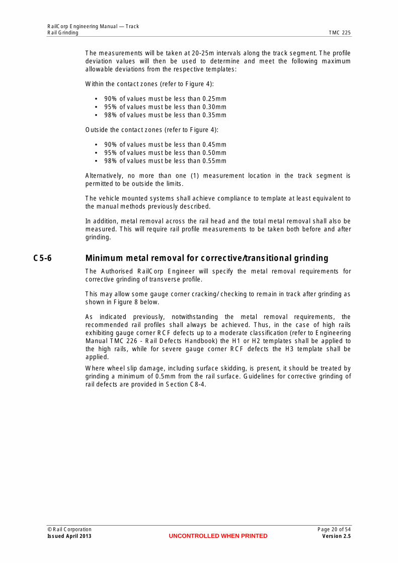
• There shall be no cyclic grinding scratch marks, as illustrated in Figure 10. Such scratch marks have the potential to develop into short pitch corrugations.
• Short pitch corrugations (30-90 mm in wavelength) shall be removed so that the remaining cyclic average longitudinal unevenness along the rail surface (peak to
© Rail Corporation Page 22 of 54 Issued April 2013 UNCONTROLLED WHEN PRINTED Version 2.5
RailCorp Engineering Manual — Track Rail Grinding TMC 225
peak) shall be less than 15µm, and the remaining longitudinal unevenness along the rail running surface shall be less than 0.05mm when measured at the centre of the running surface over any 1m length, using a suitable measuring system. Generally, the assessment of corrugations shall be conducted at the checking location. However, additional measurements may be conducted at any location within a ground section in which visual examination may indicate the presence of cyclic irregularities after grinding.
• Longer pitch corrugations (about 200-450mm in wavelength) shall also be removed, so that the remaining average longitudinal unevenness along the rail running surface (peak to peak) shall be less than 0.1mm over any 1m length unless otherwise authorised by the Authorised RailCorp Engineer. The assessment procedure shall be the same as that adopted for short pitch corrugations.
• There shall be no overheating (bluing) of the rail surface.
• In noise sensitive regions the surface shall be no rougher than an average of 6µm RA, while in other regions the surface shall be no rougher than an average of 10µm RA.
• Note that poor quality surface finish (as illustrated in Figure 11) will increase rail noise and may enhance the development of future rail surface defects.
• The resultant surface roughness shall be measured with a Surtronic 3+ roughness measuring system, or equivalent authorised by the Chief Engineer Track, using a measurement travel of 25mm. Any surface roughness measurements shall be taken at the checking locations, and will consist of three longitudinal traverses taken as follows:
– In low and tangent rails – at the rail centre line and 10-15mm on each side of the centre.
– In high rails – at the centre line and at angles of approximately 10° and 20° towards the gauge corner.
Figure 10 - Example of unacceptable cyclic grinding scratches
© Rail Corporation Page 23 of 54 Issued April 2013 UNCONTROLLED WHEN PRINTED Version 2.5

RailCorp Engineering Manual — Track Rail Grinding TMC 225
Figure 11 - Example of unacceptable severe grinding scratches
C5-9 Monitoring and control
C5-9.1 Inspection of grinding by Grinding Supervisors
Check the achievement of grinding tolerances, metal removal and surface roughness on completion of the grinding work and prior to the running of trains as follows.
1. Examine checking locations for profile, metal removal and surface roughness
2. Check the remainder of the rail visually to ensure that the specified defect removal and surface condition requirements has been achieved.
3. Where vehicle mounted rail profile measuring system have been used:
o record profile deviations from the template and metal removals at each checking location, then
o measure and record profile deviations, metal removal and surface roughness on at least three checking locations for each grinding shift.
4. Check the required contact band width on the running surface (indicated in Section C5-4.2) by painting the running surface of the rails at the checking locations following grinding, and inspecting after a minimum of at least 3 or 4 trains or preferably after several days of operations. A preliminary check of the running band can be conducted using the contacts achieved by the wheels on the rail grinder.
5. Note any abnormal observations (i.e. when the actual contact band is outside the recommended limits) and notify the Authorised RailCorp Engineer to arrange for monitoring for possible future action.
Note: When taking rail profiles with the ‘Railmate’ system, the cant bar must be used at all times to allow compensation for any deviations from the design rail cant of 1:20.
Alternative inspection/monitoring regimes that provide equivalent measurement of compliance may be approved by the Chief Engineer Track.
C5-9.2 Monitoring by Authorised RailCorp Engineer
Rail condition needs to be monitored during the grinding cycle as follows:
1. Carry out spot checks of rail grinding on at least 5% to 10% of grinding locations as a follow up to the grinding operation.
© Rail Corporation Page 24 of 54 Issued April 2013 UNCONTROLLED WHEN PRINTED Version 2.5
RailCorp Engineering Manual — Track Rail Grinding TMC 225
The spot checks will evaluate the rail grinding efficiency and the continued effective functioning of the profiles in terms of the contact bands evident and any other rail surface anomalies.
Investigate variations to the designed contacts and report major anomalies to the Chief Engineer Track.
2. Carry out a visual inspection of all ground track at about 60% to 70% of the way through the planned grinding period.
Where inspections identify any unusual deterioration conditions these are to be registered and an appropriate response determined. Additional inspections are to be scheduled for such locations. The timing will depend on the condition assessment.
C5-9.3 Records
The technical details for either preventive or corrective rail grinding, which need to be recorded in an electronic database by the Grinding supervisors are as follows:
• Grinding machine. • Date of grinding and inspection. • Location of grinding carried out (start and end points), to closest 5 metres. • Location of checking points, to closest 5 metres. • Nature of the grinding strategy adopted (e.g. preventive/transitional/corrective/
defect). • Grinding template(s) used. • Rail type and size. • Effective track kilometres ground (work completed satisfactorily). • Location of any section within a track segment that has not been ground, and the
reason for not grinding (for example: high ballast, crossing, etc.). • Minimum metal removal at the rail centre line, to the closest 0.05mm. • Deviations of the rail profile from the template. • Surface roughness achieved after grinding. • Number of grinding passes applied to each rail. • Grinding efficiency of machine, i.e. number of grinding motors working. • Details of any condition from pre-grinding inspection or any other specific
inspections of rail condition. • Details of the rail contact band assessments carried out immediately after grinding. • Details of any non-conformances in the grinding process or standard of completion.
The above information shall be available in daily form within 24 hours of the end of each shift, and in weekly form within 48 hours of the completion of each week’s work.
© Rail Corporation Page 25 of 54 Issued April 2013 UNCONTROLLED WHEN PRINTED Version 2.5

RailCorp Engineering Manual — Track Rail Grinding TMC 225
Chapter 6 Rail grinding in turnouts
C6-1 Rail profiles
C6-1.1 Rail Profiles and associated templates
Select the profile specified for turnouts in Section C5-2.1.
C6-2 Preparation for grinding
C6-2.1 Turnout geometry
Grinding should be conducted on track that has good top and line, preferably after the turnout has been surfaced.
C6-2.2 Rail condition assessment
Visually assess rail condition before grinding.
This assessment will assist in determining the maintainer specified requirements for the grinding operation.
C6-2.3 Remove track obstructions
Identify all track obstructions that prevent grinding within or adjacent to the turnout/(s). This includes:
• high ballast • lubricators • wayside monitoring devices
The amount of protrusion allowed may vary depending on the characteristics of the grinding machine being used. This should be confirmed prior to the inspection being carried out.
Remove all track obstructions that prevent grinding within a section prior to grinding and replace them after grinding in accordance with the requirements specified by the Authorised RailCorp Engineer.
C6-2.4 Track to be ground
It is permissible to grind only the through road or the turnout road of a turnout. Normally this occurs when one road (the one to be ground) is dominant. If only one road is to be ground consideration needs to be given to the fit of both switches to the stockrails and their relationship to train wheels.
C6-3 Application of templates and associated tolerances
C6-3.1 Placement
Rail template placement requirements are given in Section C5-4.1.
© Rail Corporation Page 26 of 54 Issued April 2013 UNCONTROLLED WHEN PRINTED Version 2.5

RailCorp Engineering Manual — Track Rail Grinding TMC 225
C6-3.2 Tolerance to template
Apply the rail template tolerance requirements given in Section C5-4.2 with the following exceptions:
• Remove ALL flow on the gauge side of rails. • The lug on the template does not have to fit snug against the gauge face of the rail
as long as the ground rail profile is no more than 2mm from the edge of the template ( 4mm from weld to weld through the crossing). There is no requirement to reduce this distance by grinding.
C6-3.3 Gauge Corner Relief
Generally any required gauge corner relief is built into the rail template and no gauge corner relief is to be applied.
C6-3.4 Field Side Relief
Generally any required field side relief is built into the template.
The Authorised RailCorp Engineer may specify additional relief requirements but only up to the tolerances specified. (See C6-3.2)
C6-4 Minimum metal removal for corrective/transitional grinding The Authorised RailCorp Engineer will specify the metal removal requirements for corrective grinding of transverse profile.
This may allow some gauge corner cracking/checking or squats to remain in track after grinding (as illustrated in Figure 12).
To minimise the amount of metal removal required, any major rail rectification, such as the repair and build-up of the nose at crossings, shall be conducted prior to the rail grinding. This will be the responsibility of the Authorised RailCorp Engineer.
An additional consideration in establishing the metal removal requirements will be the level of rectification required to reduce/control any excessive vertical dipping that may exist at the aluminothermic welds.
Figure 12 - Acceptable residual gauge corner defects after grinding
C6-5 Minimum metal removal for preventive grinding Metal removal requirements are as specified in Section C5-7 except where the Authorised RailCorp Engineer makes allowance for lesser metal removal. (see Section C6-3.2).
© Rail Corporation Page 27 of 54 Issued April 2013 UNCONTROLLED WHEN PRINTED Version 2.5

RailCorp Engineering Manual — Track Rail Grinding TMC 225
Tangent Rail Template, MT
C/L
8-10mm
Figure 13 – New 60 Kg rail in turnout with tangent (MT) template
Figure 13 provides an illustration of the tangent profile (MT) in relation to a new 60 kg rail. It is evident that considerable amount of material needs to be removed particularly from the gauge corner region of the new rails. This is because the rails in turnouts are not canted, as the main line rails, and hence do not match the wheel profiles. For new rails, the grinding would not extend beyond 8-10mm on the field side of the rail centre line, as illustrated in Figure 13.
The MT profile exhibits an undercut in the gauge corner region, to ensure that wheel/rail contact is made near the centre of the running surface, rather than the gauge corner region, of the turnout rails.
However, special care is required to ensure that excessive grinding of the stock rail towards the tip of the switch (as illustrated in Figure 14) is avoided. This can occur due to the double grinding of the stock rails, with the switch both closed and open.
Figure 14 - Unacceptable excessive gauge corner grinding on the stock rail near the switch tip
© Rail Corporation Page 28 of 54 Issued April 2013 UNCONTROLLED WHEN PRINTED Version 2.5

RailCorp Engineering Manual — Track Rail Grinding TMC 225
C6-6 Surface finish
C6-6.1 Grinding facets
The requirements for rail surface finish are given in Section C5-8.1.
C6-6.2 Other surface irregularities
The requirements for identification and removal of other surface irregularities are given in Section C5-8.2.
C6-7 Grinding operation 1. Conduct the initial grinding of turnouts on the through road, and continuing
beyond the points and crossing for a distance of 10-20m or as required to overlap with the plain track grinding. The overlap will require feathering in do avoid excessive metal removal.
2. Grind the turnout road from the end of the switch (to avoid additional grinding of the rails on the through road). Continue grinding beyond the crossing for 15 to 20m or as required to complete a full crossover. (The pick up and put down points in the area of the switch will need to be modified depending on a number of factors. These include the need not to over grind in the area of the switch tip, the need to marry up the profile of the switch and the stockrail in the region of the switch tip, the presence of a joggled stock rail and the need to remove metal from the field side of the stock rail.)
3. In new turnouts, grind all possible parts of the turnout and/or crossing, including switches, closure and stock rails. This will require the resetting of switches during the grinding operation. (Signalling and other support requirements for this must be in place for restoration of the work).
Generally, standard grinding passes can be applied up to 500mm from the nose of the crossings (this depends largely on the configuration and limitations of the grinding machine) and up to 1m from the tip of the switches. Take special care with the grinding applied within these distances to ensure that excessive metal is not removed. For those parts that can still be ground, this will usually entail the application of only a limited number of grinding passes to clean up the gauge corner region and reduce the plastic flow lipping (refer to Figure 15 and Figure 16).
Figure 15 - Acceptable grinding finish at switch and stock rails
© Rail Corporation Page 29 of 54 Issued April 2013 UNCONTROLLED WHEN PRINTED Version 2.5

RailCorp Engineering Manual — Track Rail Grinding TMC 225
Figure 16 - Acceptable grinding finish at switch and stock rails
From the point where the crossing is about 35-45mm wide (refer to Figure 17), grinding is to be in the trailing direction only. In this zone, the machine grinding of the top surface of the nose should be avoided.
Crossing nose width 35-45mm
Caution to be used if machine grinding conducted, No grinding on top surface
or hand grind only.
Figure 17 – Grinding of Crossing Nose
4. Some areas of the turnout may not be able to be ground by current on-track grinding machines (normally towards the tip of the switches and the crossing nose). In these cases, use suitable hand held grinding devices to cover the areas that require grinding. In addition hand held grinders may also be used to grind any anomalies on the gauge face of the rail (such as rail flow), which similarly have been missed by the on-track grinding machines.
5. In worn turnouts, the regions that should not be ground with the rail grinding machine include the following (refer to Figure 18):
o Within 500mm from the theoretical point of the crossing nose, or about 300mm from the practical point.
o Within 50-100mm from the approach to the crossing throat or set point and beyond on the wing rails.
o Over the transfer region on the wing rails.
6. Take special care towards the end of the switch to ensure that the top of the switch blade is no higher than the running surface of the stock rail and preferably about 5mm lower, as illustrated in Figure 15. This is essential to provide the back of the switch blade with appropriate lateral support by the stockrail; otherwise the top of the switch blade may break off, as illustrated in Figure 19.
7. Note that towards the nose end of the crossing region the standard MT template cannot be used to check profiles. The profile can be assessed using a modified MT template that extends from the gauge corner up to an angle of 1º towards the gauge region (refer to Figure 1), with a 1:10 run off, as illustrated in Figure 20.
© Rail Corporation Page 30 of 54 Issued April 2013 UNCONTROLLED WHEN PRINTED Version 2.5

RailCorp Engineering Manual — Track Rail Grinding TMC 225
8. At the completion of grinding blow, vacuum or wash down (using pressurised water) switch chair plates and all insulated connections to remove grinding particles/dust. Apply any necessary lubrication to the chair plates and ensure that the switches are working properly. (Signalling staff will be required to ensure the switches are working properly).
Note: in areas of slab track, remove filings from all ground areas. Filings will lay on the slab and may be blown by wind or train movement to sensitive track areas.
9. Hand grind areas of the turnout where the Grinding machine could not reach and to carry out the following functions.
o Remove flow from the area of the crossing nose. Shape the crossing to the required profile, as specified in Section C5-6 of Civil Engineering Manual TMC 222.
o Remove flow and burring from the back of the switch and run a 1mm chamfer on the corner of the top and back of the switch.
o Remove any remaining flow on the stockrail where the switch needs to fit against the stockrail.
No Grind
No Grind
Figure 18 – Regions in worn crossing that should not be ground with grinding machine
Figure 19 – Example of failure at end of switch
© Rail Corporation Page 31 of 54 Issued April 2013 UNCONTROLLED WHEN PRINTED Version 2.5

RailCorp Engineering Manual — Track Rail Grinding TMC 225
Figure 20 – Modified MT template
C6-8 Monitoring and control
C6-8.1 Inspection of grinding by Grinding Supervisors
Check the achievement of grinding tolerances, metal removal and surface roughness on completion of the grinding work and prior to the running of trains as follows:
1. Examine checking locations for profile, metal removal and surface roughness.
Check profiles at the following locations
o switches, o stockrails, o crossings, and o in the approximate middle of the turnout
No paint-marking of checking locations is required.
2. Check the remainder of the turnout visually to ensure that the specified defect removal and surface condition requirements have been achieved, as specified by the Authorised RailCorp Engineer.
3. Closely examine visually crossings, switches and stockrails.
4. Check the required contact band width on the running surface (indicated in Section C5-4.2) by painting the running surface of the rails at the checking locations following grinding, and inspecting after at least 3 or 4 trains.
5. Note any abnormal observations (i.e. when the actual contact band is outside the recommended limits) and notify the Authorised RailCorp Engineer to arrange for monitoring for possible future action.
6. Check the fit of the switch and stockrail as shown below. Grinding will change the relationship of the wheel to the rail and may increase the risk of a wheel striking the front edge of the switch.
o Standard 53 kg. Use the switch tip gauge as shown in TMC 203 Section 233 to ensure wheels will not hit leading edge of the switch. If the switch fails
© Rail Corporation Page 32 of 54 Issued April 2013 UNCONTROLLED WHEN PRINTED Version 2.5

RailCorp Engineering Manual — Track Rail Grinding TMC 225
the examination grind sufficient metal from the switch tip till it the switch tip gauge fits.
o Heavy Duty switch opposite Housing. No check is required as the housing keeps the wheel flange away from the gauge corner.
o Heavy Duty 53 switch not opposite housing. Place a 1.5 metre straight edge along the running face of the rail in front of the points. Slide the straight edge towards the points. If the end of the straight edge hits the end of the switch grind a “knife edge” at the tip of the switch that will deflect a wheel onto the correct path.
o 60 kg conventional switch. Check with a switch tip gauge. Due to 60kg switches being ”undercut” it is unlikely that any switches will fail. Iif the switch tip fails grind the switch tip sufficiently till it passes.
o 60 kg tangential switch. Visually check the tip of the switch sits below the Gauge face of the stock rail.
C6-8.2 Records
The requirements for recording of information for turnout grinding are detailed in Section C5-9.3 with the following additional records:
− Location of turnout on which grinding was carried out specifying from and to km, description of the turnout (e.g. crossover, diamond, catchpoints) and the points number(s).
− Effective track kilometres ground (work completed satisfactorily) counting both the mainline and turnout road.
© Rail Corporation Page 33 of 54 Issued April 2013 UNCONTROLLED WHEN PRINTED Version 2.5

RailCorp Engineering Manual — Track Rail Grinding TMC 225
Chapter 7 Guidelines for grinding decisions The following information is provided for use by Authorised RailCorp Engineers to make determinations of grinding requirements for both plain track and turnout grinding. Where specific requirements are required for turnout grinding they have been separately identified.
C7-1 Application of templates In the case of predominantly freight operations the RL2 template may require substantial metal removal particularly when rail has never been ground (or not ground for some considerable time). For such cases the application of the ML1 template is recommended, as part of a transitional grinding strategy. It will bring about a substantial improvement. If tread hollowed wheels are still causing problems then the RL2 template should be used (refer to Section C5-4.4 for Field Side Relief).
The MT template may be approved for application to sharper radii down to 780m radius after an assessment of the particulars of the location, the rail performance and the operational requirements. A major criterion is whether noticeable gauge face wear is occurring in the high rails. If negligible wear is present then the MT profile may be used.
The Authorised RailCorp Engineer may also approve and direct application of the H3 high rail template in sharper curves in which the high rails exhibit severe gauge corner RCF or squat defects, as part of a transitional grinding strategy.
C7-2 Application of the locating lug on low rail and tangent rail templates Specify the application requirements for the locating lug on low and tangent rail templates (beyond those given in Section C5-4.2). This may take the form of a strategy to bring the template into conformance over successive grinding cycles as described in Section C54.2.
In adopting the above procedure, appropriate matching of the lug and the side of the rails will be achieved within three grinding cycles, and any plastic flow of the rail in the gauge corner region will be progressively removed.
C7-3 Gauge corner relief Specify any special gauge corner relief requirements by the application of the H3 template (see SectionC7-1).
Gauge corner undercutting leads to two point wheel/rail contact conditions in the sharper curves as illustrated in Figure 6.
When using the H3 template, the template tolerances and grinding facet limits as specified in Section C5-8.1 must still be observed.
More details of the procedure to be adopted in these special cases are given in Section C5-3.4.
Gauge corner relief is not applicable in turnouts.
C7-4 Field side relief Specify field side relief additional to that specified in Section C5-4.4 when, after the application of the normal templates, there is still evidence of excessive tread hollowing on
© Rail Corporation Page 34 of 54 Issued April 2013 UNCONTROLLED WHEN PRINTED Version 2.5

RailCorp Engineering Manual — Track Rail Grinding TMC 225
wheels (this is normally observed as a well-developed contact band extending beyond the contact bands shown in Appendix A and towards the field side of the rail head).
Under the above circumstances, additional field side relief needs to be applied to ensure that minimum wheel contact occurs in the field side region, i.e. within approximately 15mm from the field side rail face. In such cases, nominate one of the following options:
For plain track
• Implement the RL2 rail profile in the low rails of curves where the ML1 has been used (the ML1 exhibits less field side relief).
For plain track and turnouts
• Implement additional field side relief in the low rails of curves (relative to the RL2 profile), or in tangent rails (relative to the MT profile). When introducing such relief, apply the required tolerances with reference to the template; namely:
– up to 0.5mm at an angle (to the horizontal) of -10 (measured anti-clockwise),and – up to 0.7mm at an angle of -20, as illustrated in Figure 4.
• Check the nominated measurements with suitable feeler gauges.
The additional field side relief should not extend into the contact zone, as illustrated in Appendix A.
An additional problem that may occur on plain track, particularly in passenger lines, is that the wheel profiles generally do not exhibit hollowing and consequently the field side of the rails may develop a coating of rust. However, if a light locomotive with hollow wheels travels over the rails and makes the primary contact on the field side, the coating could act as an insulator and cause loss of shunt. Such locations have been separately identified. Only tangent rails are affected by this problem.
The grinding facet limits as specified in Section C5-8.1 must also still be observed within the field relieved zone.
There is no requirement to address these problems in turnouts.
C7-5 Minimum metal removal for preventive grinding in turnouts When grinding relatively new turnouts for the first time reduce the specified minimum depth of metal removal on the contact surface (0.2mm) to 0.0 mm near the field side edge of the contact surface (refer to Figure 16). This will reduce the metal removal requirements.
C7-6 Minimum metal removal for corrective grinding Specify the metal removal requirements for corrective grinding. These arise primarily because of rolling contact fatigue or squat defects present in rails that have not been cyclic ground. Such damage may inhibit the routine ultrasonic inspection of the rails, particularly if located in the gauge corner region (gauge corner checking and squats).
Complete removal of the severe gauge corner checking and squat defects is generally NOT recommended as it requires considerable metal removal, and hence rail grinding effort, and it removes protective work hardened material from the surface. (See Figure 8 for plain track and Figure 12 for turnouts).
© Rail Corporation Page 35 of 54 Issued April 2013 UNCONTROLLED WHEN PRINTED Version 2.5

RailCorp Engineering Manual — Track Rail Grinding TMC 225
The recommended procedure to be implemented in these cases is as follows:
• Remove a minimum of 0.2mm (and usually more than 0.4-0.5mm) of metal from all contact surfaces including the gauge region, as specified in Section C5-7 for plain track or C6-5 for turnouts.
• Ensure that all checking cracks have been removed from the running surface above the rail web, and preferably from a distance of 20-25mm from the gauge corner (exclusive) towards the field side. As illustrated in Figure 8 for plain track and Figure 12 for turnouts, some gauge corner checking may be left on the rails.
• Establish the recommended profiles, and where the gauge corner is affected implement the H3 template on the high rails, to reduce the gauge corner contact for a limited time. It should be emphasised that the grinding facet limits as specified in Section C5-8.1 must also still be observed within the gauge corner relieved zone.
• Note the track sections in which the above procedure has been implemented, so that (depending on the degree of damage) in following grinding cycles the additional gauge corner relief may be able to be reduced to within the normal limits specified in Section C5-4.2 for plain track and Section C6-3.2 for turnouts.
It is emphasised however that the above procedure should not be required when the rails have been subjected to a number of preventive grinding cycles.
Where wheel slip damage, including surface skidding is present, it should be treated by grinding a minimum of 0.5mm from the rail surface. Guidelines for corrective grinding of rail defects are provided in Section C8-4.
C7-7 Transitioning the removal of long wavelength corrugations Establish transition arrangements where considerable grinding effort is required to achieve full correction to profile or to remove long wavelength corrugations or severe RCF and squat defects. These must involve the correction of the problem over time such that each grinding cycle brings about a progressive improvement.
However, in all such cases the appropriate rail profile must be established, within the tolerance limits specified in Section C5-4.2.
Transition arrangements are not applicable in turnouts.
© Rail Corporation Page 36 of 54 Issued April 2013 UNCONTROLLED WHEN PRINTED Version 2.5

RailCorp Engineering Manual — Track Rail Grinding TMC 225
Chapter 8 Grinding strategy
C8-1 General The grinding strategy contains:
• mandatory requirements for grinding new rail and other rail where its orientation has been altered
• mandatory requirements for grinding new turnouts (or new turnout steelwork where existing bearers are kept);
• guidelines for preventive grinding • guidelines for corrective grinding.
The requirements are applicable to main line track classifications in RailCorp. Where targeted grinding strategies have been approved for specific lines or districts by the Chief Engineer Track, then these will take precedence.
The guidelines are provided for the preventive grinding strategy and as such will provide an indication of the minimum rail grinding requirements. In the initial stages additional grinding may be necessary to rectify defective track sections.
The strategy does not cover manual grinding for minor maintenance associated with crossings and switches.
C8-2 Grinding of new or reoriented rail (mandatory requirements) For plain track
In tracks with heavy duty and general freight traffic, grind any new rails placed in track as part of rerailing (and not as closures for replacement of defects) to profile within 5 MGT (or 20% of the grinding cycle for preventive grinding as indicated in Table 2 whichever is the larger) following the re-railing. This shall apply even if the re-railing occurs in only part of a curve or section.
In tracks with passenger traffic only, the maximum tonnage for grinding of new rails may be extended to 10 MGT.
Special care is required in sections within which partial re-railing has occurred between grinding cycles. In these sections, the new rails will require some additional initial grinding prior to the final profile grinding applied to the whole section.
In addition, special grinding is required when the rail orientation is substantially altered. In such cases the grinding shall be applied within 5 MGT (or 20% of the grinding cycle for preventive grinding whichever is the larger) following the event. Applicable situations include:
• Reuse of rail when concrete sleepers are installed. • Reuse of rail when substantial backcanting is corrected. • Cascading or transposing of rail.
For turnouts
Grind any new turnouts to profile within 8 MGT for standard carbon rails and Manganese crossings and 10 MGT for Head Hardened rails (or 20% of the grinding cycle for preventive grinding detailed in Table 3, whichever is the larger) following installation.
© Rail Corporation Page 37 of 54 Issued April 2013 UNCONTROLLED WHEN PRINTED Version 2.5

RailCorp Engineering Manual — TrackRail Grinding TMC 225
C8-3 Guidelines for preventive grinding For plain track
The recommended guidelines for preventive rail grinding are summarised in Table 2.
The following requirements are extracted from RailCorp standard ESC 100.
Nominal Period Between Grinds (MGT)
Tracks with Heavy Duty
Freight Traffic
Tracks with General Freight Traffic or Empty
Heavy Duty Freight Traffic
Tracks with Passenger
Traffic Track Curvature (m)
Std HH Std HH Std HH
450 or less NA 20 15 20 20 30
> 450 to 1000 10 20 15 20 20 30
> 1000 20 30 25 35 30 40
Examples of lines representing the above traffic types would be:
• Illawarra Down Track and Blue Mountains Up Track for the Heavy Duty Coal/Freight Traffic.
• Illawarra Up Track, Blue Mountains Down Track and Metro North to Vales Point for the General Freight Traffic or Empty Heavy Duty Coal/Freight Traffic.
• Cronulla, Eastern Suburbs, East Hills, Inner City, City Circle, Bankstown and North Shore Lines for Passenger Traffic.
To allow for track possession and grinding irregularities a tolerance of 3MGT may be applied to the nominal grinding period or up to 20% of the recommended cycle tonnages given in Table 2 (whichever is the larger). The nominal grinding period however will generally be maintained.
Because of adverse wheel/rail contact conditions, the grinding cycles in Table 2 might not be suitable for some track sections. Such sections should be reported, monitored and if necessary adjusted to a different cycle category. An example could be rails subjected to higher tractive efforts which may exhibit higher deterioration rates and hence would require more frequent grinding.
The nominal grinding period between grinds in Table 2 should be achieved at least on average. If necessary individual cycles may be adjusted to suit particular circumstances but generally within the maximum allowable periods given in Table 2.
The curve classes and the grinding frequencies given in Table 2 may change in the future, depending on the characteristics of the rail performance observed between grinds, and recognising that the most efficient strategy would consist of grinding cycles which are multiples of each other, thus allowing relatively long sections of track, containing several curve classes, to be covered at any one time.
To improve the logistics of the grinding operation and hence efficiency, the Authorised RailCorp Engineer may program the rail grinding to cover track sections containing different curve classes at the same time, even though the shallower curves may be within the specified cycles. In this case, as discussed in Section C5-7, the metal removal
Table 2 - Guidelines for preventive grinding
© Rail Corporation Page 38 of 54Issued April 2013 UNCONTROLLED WHEN PRINTED Version 2.5

RailCorp Engineering Manual — TrackRail Grinding TMC 225
requirements in the shallower curves may be reduced, as long as the minimum metal removal is achieved within the specified cycles.
For turnouts
The recommended guidelines for preventive rail grinding are to be the more stringent of the requirements for the main line as given in Table 2 and for the turnout road as given in Table 3. Note that tonnages on the turnout road are to be used in Table 3.
The following requirements are extracted from RailCorp standard ESC 100.
Nominal Period Between Grinds (MGT)
Turnout Type Rail Type
1:8.25 1:10.5 1:15 or higher
Head Hardened 13 18 25
Standard Carbon 8 13 18
Table 3 - Guidelines for preventive grinding of turnout road
To allow for track possession and grinding irregularities a tolerance of up to 20% of the recommended cycle tonnages given in Table 3 is applicable. The nominal grinding period however should generally be maintained.
Because of adverse wheel/rail contact conditions, the grinding cycles in Table 2 and Table 3 might not be suitable for some track sections. Such sections should be reported, monitored and if necessary adjusted to a different cycle category. An example could be rails subjected to higher tractive efforts that may exhibit higher deterioration rates and hence would require more frequent grinding.
Whilst it is recommended that grinding of turnouts be undertaken as described above, it is recognised that there may be limitations on resources. The primary requirement is to grind turnouts to establish appropriate profiles. Where grinding resources are limited, follow up grinding frequencies may be relaxed.
C8-4 Corrective grinding Special grinding requirements apply for the treatment of various rail surface defect conditions. These will require separate assessment and must be dealt with on a case by case basis. The more serious of these will be identified by the track examination process and suitable remedial measures planned in advance. Lesser conditions that are uncovered in the pre-grinding inspection may be dealt with in association with the normal grinding operation. If this cannot be done economically the work will be rescheduled for special treatment at a later date.
Localised defects such as isolated squats or dipped welds may be more effectively treated by other means. These would be best applied prior to grinding which would then achieve a better final finish.
Rails that have been subjected to wheel slip damage are prone to squat development. Surface damage created by wheels which are moving and slipping at the same time should be treated by grinding a minimum of 0.5mm from the rail surface. Wheel burns, created by a stationary spinning wheel, are usually deeper and require alternative treatment such as wire feed welding. These rails should also be ground to remove 0.5mm, to ensure that all heat affected material is removed from adjacent rail surfaces.
© Rail Corporation Page 39 of 54Issued April 2013 UNCONTROLLED WHEN PRINTED Version 2.5

RailCorp Engineering Manual — Track Rail Grinding TMC 225
Grinding to remove squats usually requires removal of some 5mm of metal from the rail surface, in order to be effective. This practice is often uneconomical. It should only be undertaken after considering the cost, residual rail life and impact on grinding resources. Smooth grinding of the rail surface will provide short term relief to noise and vibration from squats.
At locations with recently developed squats, consideration should be given to grinding to remove 0.5mm from the rail surface. The purpose of this action is to remove any residual heat affected material from the rail surface. It will not remove the existing squats, but is intended to prevent the development of more squats. It should be restricted to locations where squats have developed without RCF involvement.
Typical defect conditions are as follows:
Condition Detail
Rail Corrugations:
Cyclic (wave like), generally vertical, irregularities on the running surface of the rails. Corrugations are thought to form from either the differential wear caused by a repetitious sliding action of the wheel on the rail, whether through acceleration, braking or lateral motion across the rail, or from plastic flow of the rail material due to excessive contact stresses and the combined resonance of the wheelset unsprung mass and the track. Corrugations are generally 0.1mm to 0.5 mm in depth and:
− Short pitch - from about 30 mm to 90 mm in wavelength, which are usually associated with the lighter axle load passenger traffic; or
− Long pitch - from about 200 mm to 450 mm in wavelength or more, which are usually associated with the heavier axle load freight or in particular coal traffic.
Wheelburns: Structural discontinuities which occur on the running surface of both rails (directly opposite) and are due to the localised slip of a locomotive wheelset. This can cause either severe localised deformation or overheating and the transformation of the rail material into a hard and brittle martensitic microstructure. The contamination of the running surface of the rails, by for example lubricants, greatly enhances the development of wheelburns.
Tread Hollowing:
A condition where there is a worn hollow in the wheel tread which is then able to make contact with the field side of the rail. Additional field side relief can moderate this problem as indicated in Chapter 7. If possible offending rollingstock should be identified and reported.
Rail Flow: Plastic flow of the rail surface material, which may occur on high, low and tangent rails, both on the field and gauge sides. It results from exceeding the yield strength of the material, which can occur because of various reasons including higher tractive effort and poor matching of wheel and rail profiles (including hollow wheels). Correction of head flow (which may be causing tight gauge) may be rectified by grinding, which shall be applied as required to address track geometry standards
Shielding ‘Shielding’ occurs where the ultrasonic testing of rail is inhibited. In this case rail grinding will be conducted at the earliest possible time following the reporting of 'shielding'. Sufficient defective metal will be removed from the rail surface to allow the ultrasonic beam to pass through the rail head, web and foot. This will be checked using manual ultrasonic inspection procedures.
© Rail Corporation Page 40 of 54 Issued April 2013 UNCONTROLLED WHEN PRINTED Version 2.5
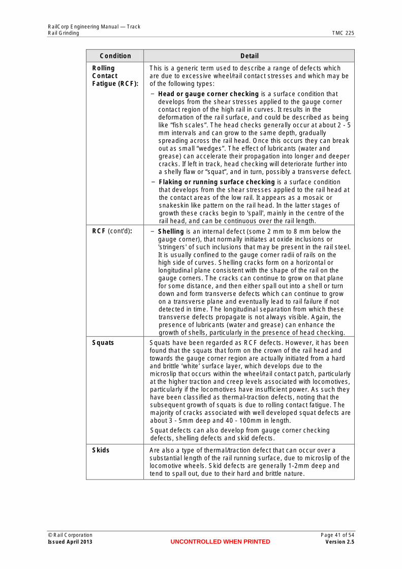
RailCorp Engineering Manual — Track Rail Grinding TMC 225
Condition Detail
Rolling Contact Fatigue (RCF):
This is a generic term used to describe a range of defects which are due to excessive wheel/rail contact stresses and which may be of the following types:
− Head or gauge corner checking is a surface condition that develops from the shear stresses applied to the gauge corner contact region of the high rail in curves. It results in the deformation of the rail surface, and could be described as being like “fish scales”. The head checks generally occur at about 2 - 5 mm intervals and can grow to the same depth, gradually spreading across the rail head. Once this occurs they can break out as small “wedges”. The effect of lubricants (water and grease) can accelerate their propagation into longer and deeper cracks. If left in track, head checking will deteriorate further into a shelly flaw or “squat”, and in turn, possibly a transverse defect.
− Flaking or running surface checking is a surface condition that develops from the shear stresses applied to the rail head at the contact areas of the low rail. It appears as a mosaic or snakeskin like pattern on the rail head. In the latter stages of growth these cracks begin to 'spall', mainly in the centre of the rail head, and can be continuous over the rail length.
RCF (cont'd): − Shelling is an internal defect (some 2 mm to 8 mm below the gauge corner), that normally initiates at oxide inclusions or 'stringers' of such inclusions that may be present in the rail steel. It is usually confined to the gauge corner radii of rails on the high side of curves. Shelling cracks form on a horizontal or longitudinal plane consistent with the shape of the rail on the gauge corners. The cracks can continue to grow on that plane for some distance, and then either spall out into a shell or turn down and form transverse defects which can continue to grow on a transverse plane and eventually lead to rail failure if not detected in time. The longitudinal separation from which these transverse defects propagate is not always visible. Again, the presence of lubricants (water and grease) can enhance the growth of shells, particularly in the presence of head checking.
Squats Squats have been regarded as RCF defects. However, it has been found that the squats that form on the crown of the rail head and towards the gauge corner region are actually initiated from a hard and brittle ‘white’ surface layer, which develops due to the microslip that occurs within the wheel/rail contact patch, particularly at the higher traction and creep levels associated with locomotives, particularly if the locomotives have insufficient power. As such they have been classified as thermal-traction defects, noting that the subsequent growth of squats is due to rolling contact fatigue. The majority of cracks associated with well developed squat defects are about 3 - 5mm deep and 40 - 100mm in length.
Squat defects can also develop from gauge corner checking defects, shelling defects and skid defects.
Skids Are also a type of thermal/traction defect that can occur over a substantial length of the rail running surface, due to microslip of the locomotive wheels. Skid defects are generally 1-2mm deep and tend to spall out, due to their hard and brittle nature.
© Rail Corporation Page 41 of 54 Issued April 2013 UNCONTROLLED WHEN PRINTED Version 2.5

RailCorp Engineering Manual — Track Rail Grinding TMC 225
RCF and squat defects are of particular concern because of the following main reasons:
1. They can lead to rail failure if not detected in time; and/or
2. They can mask the ultrasonic signal during routine inspection and hence prevent the detection of larger and deeper defects that may be present within the rail; and/or
3. Their rectification requires considerable amounts of metal removal; and/or
4. Severe squat defects can lead to a considerable increase in the wheel/rail noise levels.
It should be noted that where considerable grinding effort is required to achieve full correction to profile or to remove long wavelength corrugations transition strategies may be utilised as outlined in Section C7-7. Such strategies must involve the correction of the problem over time such that each grinding cycle brings about a progressive improvement. It is recommended that expert advice should be sought for the development of such strategies.
© Rail Corporation Page 42 of 54 Issued April 2013 UNCONTROLLED WHEN PRINTED Version 2.5

RailCorp Engineering Manual — Track Rail Grinding TMC 225
Chapter 9 Template fabrication and calibration
C9-1 Template fabrication Manufacture the rail template as follows:
1. Manufacture rail templates from hardened steel (or a product of equivalent or superior strength, wear resistance, dimensional stability and durability) to a tolerance of ± 0.025 mm at the profile surfaces.
2. Tolerances at the fixing points for connection to the gauge bar must be adequate to ensure that overall superelevated profile tolerances (as detailed below) are not compromised.
3. Permanently scribe the template name, date of manufacture and designed contact band details (including position of the contact bands and the contact angles) on the face of the template.
4. Manufacture the template with the 1 in 20 (2.86%) rail cant included, noting that the co-ordinates for the various templates given in Appendix A are for vertical rails and do not include the allowance for rail cant.
C9-2 Gauge bar fabrication Use a gauge bar with the rail template. Manufacture the gauge bar as follows:
1. Manufacture the gauge bar from mild steel, aluminium or other product of equivalent or superior strength, dimensional stability and durability. The gauge bar must be insulated so that there is no electrical contact between the rails during its application.
2. The gauge bar shall have fixing holes matching those on the template.
3. The gauge bar is to provide a reference to the other rail to give a super-elevated reference plane for the application of the template to within ± 0.2 degrees (ie. a deviation of less than 2.6 mm from a 1.5m straight edge).
Figure 21 illustrates a gauge bar that could be used to hold the profile template and applied for quality assurance during rail grinding.
© Rail Corporation Page 43 of 54 Issued April 2013 UNCONTROLLED WHEN PRINTED Version 2.5

RailCorp Engineering Manual — Track Rail Grinding TMC 225
100
1600
10 x 30 x 100 (nominal) insulation pad attached to bar
template holder
60 15
20
10 mm tapped holes to secure templates
110 x 40 x 10 plate with 90 x 30 x 3 recess to locate rail templates
~30 mm square tube
plate welded to bar
insulation pad
Figure 21 - Holding Bar for template
C9-3 Calibration 1. Check template calibration at initial fabrication and thence six-monthly.
The template must be within 0.05mm at manufacture and thence within 0.1 mm of the designed shape.
Conduct the calibration with the template fitted to the gauge bar or with a suitably designed calibration block that will allow the proper alignment and matching of the template and the calibration block.
If a calibration block is used it must be within 0.05 mm of the design geometry.
2. Check the gauge bar against a straight edge at monthly intervals to ensure that it has not been deformed.
The gauge bar needs to be within the original specification of ± 0.2 degrees (ie. a deviation of less than 2.6 mm from a 1.5m straight edge).
© Rail Corporation Page 44 of 54 Issued April 2013 UNCONTROLLED WHEN PRINTED Version 2.5

RailCorp Engineering Manual — Track Rail Grinding TMC 225
3. Any other equipment (including electronic measuring devices and vehicle mounted systems) used in the application or verification of templates and rail profiles must meet equivalent calibration and repeatability requirements.
© Rail Corporation Page 45 of 54 Issued April 2013 UNCONTROLLED WHEN PRINTED Version 2.5

RailCorp Engineering Manual — Track Rail Grinding TMC 225
Appendix A Rail Profiles
Extract from ESC 220.
Modified Tangent (MT) Tangent and Shallow Curves Template With Lug
Coordinates of Contact Band
Mainly Passenger Traffic Mainly Freight Traffic
Min Contact Band Max Contact Band Min Contact Band Max Contact Band
-9 -15 -12.5 -17.5
+9 +15 +12.5 +17.5
X-Y Co-ordinates
X -40.00
-35.96
-35.23
-34.50
-33.28
-32.42
-31.56
-30.70
-29.84
-28.98
-28.12
-27.26
-26.40
-25.54
-24.68
-23.82
-22.95
-22.09
-21.23
-20.37
-19.51
-18.65
-17.78
-16.92
-16.06
-15.20
-14.34
-13.47
-12.61
Y X Y X Y -3.08 -11.75 -0.55 17.88 -1.35
-2.42 -10.88 -0.53 19.20 -1.59
-2.32 -10.02 -0.51 20.53 -1.85
-2.22 -9.16 -0.50 21.43 -2.04
-2.06 -8.29 -0.48 22.38 -2.27
-1.95 -7.43 -0.47 23.33 -2.54
-1.85 -6.57 -0.45 24.28 -2.85
-1.74 -5.70 -0.44 25.23 -3.21
-1.64 -4.84 -0.42 26.19 -3.61
-1.54 -3.97 -0.41 27.15 -4.06
-1.45 -3.11 -0.40 27.79 -4.40
-1.36 -2.24 -0.40 28.44 -4.79
-1.27 -1.38 -0.40 29.09 -5.22
-1.18 -0.51 -0.40 29.74 -5.70
-1.10 0.35 -0.40 30.39 -6.24
-1.02 1.22 -0.41 31.05 -6.86
-0.94 2.08 -0.42 31.71 -7.56
-0.90 2.95 -0.44 32.37 -8.37
-0.85 3.81 -0.45 33.05 -9.32
-0.81 4.68 -0.48 33.73 -10.48
-0.77 5.99 -0.50 36.28 -10.35
-0.74 7.31 -0.52 36.45 -13.71
-0.71 8.63 -0.55 35.00 -13.77
-0.69 9.95 -0.59 35.25 -18.76
-0.67 11.27 -0.64
-0.65 12.59 -0.70
-0.62 13.91 -0.82
-0.59 15.23 -1.00
-0.57 16.55 -1.15
Note: The profile has been specified for a free standing rail centreline using the above coordinate system incorporating the rail centreline. Therefore when producing rail profile templates a cant adjustment of 1:20 (2.86°) clockwise rotation must be added so that the profile is referenced perpendicular to the track plane.
© Rail Corporation Page 46 of 54 Issued April 2013 UNCONTROLLED WHEN PRINTED Version 2.5

RailCorp Engineering Manual — TrackRail Grinding TMC 225
Extract from ESC 220.
RPH2000 (H1) High Rail Template for curved track - Without Lug Rail Centreline Max Contact Band
5.4 mm Min Contact Band
14.4 mm
0
-45 -40 -35 -30 -25 -20 -15 -10 -5 -2 0 5 10 15 20 25 30 35 40-4-6
Template: RPH2000 Rail Contact X-8 -10 Run-Off -12 -14
Not to Scale
Note: Rail Centreline corresponds to X Co-ordinates (mm) (-1.3, 0.0) point on template
X-Y Co-ordinates
Y C
o-or
dina
tes
(mm
)
X Y X Y X Y X Y -40 -2.35
-35 -1.86 -13 -0.17 9 -0.32 20.75 -1.57
-34.5 -1.81 -12.5 -0.15 9.5 -0.35 21 -1.62
-34 -1.77 -12 -0.14 10 -0.38 21.25 -1.68
-33.5 -1.72 -11.5 -0.12 10.5 -0.4 21.5 -1.74
-33 -1.67 -11 -0.11 10.75 -0.42 21.75 -1.8
-32.5 -1.62 -10.5 -0.09 11 -0.43 22 -1.86
-32 -1.57 -10 -0.08 11.25 -0.45 22.25 -1.93
-31.5 -1.52 -9.5 -0.07 11.5 -0.47 22.5 -1.99
-31 -1.47 -9 -0.06 11.75 -0.48 22.75 -2.07
-30.5 -1.43 -8.5 -0.05 12 -0.5 23 -2.14
-30 -1.38 -8 -0.04 12.25 -0.52 23.25 -2.22
-29.5 -1.33 -7.5 -0.03 12.5 -0.54 23.5 -2.3
-29 -1.28 -7 -0.02 12.75 -0.56 23.75 -2.38
-28.5 -1.23 -6.5 -0.02 13 -0.58 24 -2.47
-28 -1.18 -6 -0.01 13.25 -0.6 24.25 -2.56
-27.5 -1.13 -5.5 -0.01 13.5 -0.62 24.5 -2.65
-27 -1.09 -5 0 13.75 -0.64 24.75 -2.75
-26.5 -1.04 -4.5 0 14 -0.66 25 -2.85
-26 -0.99 -4 0 14.25 -0.69 25.25 -2.96
-25.5 -0.95 -3.5 0 14.5 -0.71 25.5 -3.08
-25 -0.91 -3 0 14.75 -0.74 25.75 -3.2
-24.5 -0.86 -2.5 0 15 -0.76 26 -3.33
-24 -0.82 -2 -0.01 15.25 -0.79 26.25 -3.46
-23.5 -0.78 -1.5 -0.01 15.5 -0.82 26.5 -3.6
-23 -0.74 -1 -0.01 15.75 -0.84 26.75 -3.75
-22.5 -0.71 -0.5 -0.02 16 -0.87 27 -3.9
-22 -0.67 0 -0.03 16.25 -0.9 27.25 -4.06
-21.5 -0.63 0.5 -0.04 16.5 -0.93 27.5 -4.22
-21 -0.6 1 -0.04 16.75 -0.96 27.75 -4.4
-20.5 -0.56 1.5 -0.05 17 -0.99 28 -4.58
-20 -0.53 2 -0.07 17.25 -1.03 28.25 -4.77
-19.5 -0.5 2.5 -0.08 17.5 -1.06 28.5 -4.96
-19 -0.47 3 -0.09 17.75 -1.09 28.75 -5.17
-18.5 -0.44 3.5 -0.1 18 -1.13 29 -5.39
-18 -0.41 4 -0.12 18.25 -1.16 29.25 -5.61
-17.5 -0.38 4.5 -0.14 18.5 -1.2 29.5 -5.85
-17 -0.35 5 -0.15 18.75 -1.23 29.75 -6.09
-16.5 -0.33 5.5 -0.17 19 -1.27 30 -6.35
-16 -0.3 6 -0.19 19.25 -1.31 31 -7.43
-15.5 -0.28 6.5 -0.21 19.5 -1.35 32 -8.51
-15 -0.25 7 -0.23 19.75 -1.39 33 -9.59
-14.5 -0.23 7.5 -0.25 20 -1.43 34 -10.66
-14 -0.21 8 -0.27 20.25 -1.47 35 -11.74
-13.5 -0.19 8.5 -0.3 20.5 -1.52
Note: The profile has been specified for a free standing rail centreline using the above coordinate system incorporating the rail centreline. Therefore when producing rail profile templates a cant adjustment of 1:20 (2.86°) clockwise rotation must be added so that the profile is referenced perpendicular to the track plane.
© Rail Corporation Page 47 of 54Issued April 2013 UNCONTROLLED WHEN PRINTED Version 2.5
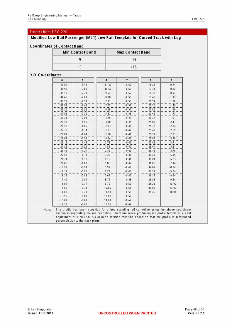
RailCorp Engineering Manual — Track Rail Grinding TMC 225
Extract from ESC 220.
Modified Low Rail Passenger (ML1) Low Rail Template for Curved Track with Lug
Coordinates of Contact Band
Min Contact Band Max Contact Band
-9 -15
+9 +15
X-Y Co-ordinates X Y X Y X Y
-40.00 -3.43 -11.37 -0.62 16.23 -0.74
-35.90 -2.80 -10.50 -0.59 17.31 -0.82
-35.17 -2.71 -9.64 -0.57 18.38 -0.97
-34.45 -2.61 -8.78 -0.55 19.46 -1.13
-33.72 -2.51 -7.91 -0.53 20.54 -1.30
-32.99 -2.42 -7.05 -0.51 21.25 -1.43
-32.26 -2.32 -6.19 -0.50 21.96 -1.56
-31.53 -2.22 -5.32 -0.48 22.66 -1.72
-30.31 -2.06 -4.46 -0.47 23.37 -1.91
-29.45 -1.95 -3.60 -0.45 24.07 -2.11
-28.59 -1.85 -2.73 -0.44 24.78 -2.34
-27.73 -1.74 -1.87 -0.42 25.49 -2.59
-26.87 -1.64 -1.00 -0.41 26.27 -2.91
-26.01 -1.54 -0.14 -0.40 27.06 -3.28
-25.15 -1.45 0.73 -0.40 27.85 -3.71
-24.29 -1.36 1.59 -0.40 28.64 -4.21
-23.43 -1.27 2.45 -0.40 29.43 -4.79
-22.57 -1.18 3.32 -0.40 30.23 -5.45
-21.71 -1.10 4.19 -0.41 31.04 -6.23
-20.85 -1.02 5.05 -0.42 31.85 -7.14
-19.99 -0.94 5.92 -0.44 32.67 -8.24
-19.12 -0.90 6.78 -0.45 33.51 -9.64
-18.26 -0.85 7.65 -0.47 36.25 -9.64
-17.40 -0.81 8.72 -0.48 36.25 -9.64
-16.54 -0.77 9.79 -0.50 36.25 -13.92
-15.68 -0.74 10.86 -0.51 35.00 -13.92
-14.82 -0.71 11.93 -0.55 35.25 -18.91
-13.95 -0.69 13.01 -0.57
-13.09 -0.67 14.08 -0.62
-12.23 -0.65 15.16 -0.68
Note: The profile has been specified for a free standing rail centreline using the above coordinate system incorporating the rail centreline. Therefore when producing rail profile templates a cant adjustment of 1:20 (2.86°) clockwise rotation must be added so that the profile is referenced perpendicular to the track plane.
© Rail Corporation Page 48 of 54 Issued April 2013 UNCONTROLLED WHEN PRINTED Version 2.5

RailCorp Engineering Manual — TrackRail Grinding TMC 225
Extract from ESC 220.
RMH2000 (H2) High Rail Template for curved track - Without Lug Rail Centreline Max Contact Band
1.5 mm Min Contact Band 10.5 mm
Y C
o-or
dina
tes
(mm
)0
-45 -40 -35 -30 -25 -20 -15 -10 0 5 10 15 20 25 30 35 40
-4
-6
-5 -2
Template: RMH2000 Rail Contact X-8
-10 Run-Off Not to Scale
-12 X Co-ordinates (mm) Note: Rail Centreline corresponds to
(-0.8, 0.0) point on template
X-Y Co-ordinates X Y X Y X Y X Y -40 -2.34
-35 -1.84 -13.25 -0.17 8.75 -0.32 20.5 -1.55
-34.75 -1.82 -12.75 -0.15 9.25 -0.35 20.75 -1.6
-34.25 -1.77 -12.25 -0.14 9.75 -0.38 21 -1.64
-33.75 -1.72 -11.75 -0.12 10.25 -0.4 21.25 -1.68
-33.25 -1.67 -11.25 -0.11 10.5 -0.42 21.5 -1.73
-32.75 -1.62 -10.75 -0.09 10.75 -0.43 21.75 -1.78
-32.25 -1.57 -10.25 -0.08 11 -0.45 22 -1.84
-31.75 -1.52 -9.75 -0.07 11.25 -0.47 22.25 -1.89
-31.25 -1.47 -9.25 -0.06 11.5 -0.48 22.5 -1.95
-30.75 -1.43 -8.75 -0.05 11.75 -0.5 22.75 -2.02
-30.25 -1.38 -8.25 -0.04 12 -0.52 23 -2.08
-29.75 -1.33 -7.75 -0.03 12.25 -0.54 23.25 -2.15
-29.25 -1.28 -7.25 -0.02 12.5 -0.56 23.5 -2.22
-28.75 -1.23 -6.75 -0.02 12.75 -0.58 23.75 -2.29
-28.25 -1.18 -6.25 -0.01 13 -0.6 24 -2.37
-27.75 -1.13 -5.75 -0.01 13.25 -0.62 24.25 -2.45
-27.25 -1.09 -5.25 0 13.5 -0.64 24.5 -2.53
-26.75 -1.04 -4.75 0 13.75 -0.66 24.75 -2.61
-26.25 -0.99 -4.25 0 14 -0.69 25 -2.7
-25.75 -0.95 -3.75 0 14.25 -0.71 25.25 -2.79
-25.25 -0.91 -3.25 0 14.5 -0.74 25.5 -2.88
-24.75 -0.86 -2.75 0 14.75 -0.76 25.75 -2.98
-24.25 -0.82 -2.25 -0.01 15 -0.79 26 -3.09
-23.75 -0.78 -1.75 -0.01 15.25 -0.82 26.25 -3.2
-23.25 -0.74 -1.25 -0.01 15.5 -0.84 26.5 -3.31
-22.75 -0.71 -0.75 -0.02 15.75 -0.87 26.75 -3.43
-22.25 -0.67 -0.25 -0.03 16 -0.9 27 -3.56
-21.75 -0.63 0.25 -0.04 16.25 -0.93 27.25 -3.69
-21.25 -0.6 0.75 -0.04 16.5 -0.96 27.5 -3.83
-20.75 -0.56 1.25 -0.05 16.75 -0.99 27.75 -3.97
-20.25 -0.53 1.75 -0.07 17 -1.03 28 -4.12
-19.75 -0.5 2.25 -0.08 17.25 -1.06 28.25 -4.28
-19.25 -0.47 2.75 -0.09 17.5 -1.09 28.5 -4.45
-18.75 -0.44 3.25 -0.1 17.75 -1.13 28.75 -4.62
-18.25 -0.41 3.75 -0.12 18 -1.16 29 -4.8
-17.75 -0.38 4.25 -0.14 18.25 -1.2 29.25 -4.99
-17.25 -0.35 4.75 -0.15 18.5 -1.23 29.5 -5.18
-16.75 -0.33 5.25 -0.17 18.75 -1.27 29.75 -5.39
-16.25 -0.3 5.75 -0.19 19 -1.31 30 -5.6
-15.75 -0.28 6.25 -0.21 19.25 -1.35 31 -6.56
-15.25 -0.25 6.75 -0.23 19.5 -1.39 32 -7.64
-14.75 -0.23 7.25 -0.25 19.75 -1.43 33 -8.72
-14.25 -0.21 7.75 -0.27 20 -1.47 34 -9.8
-13.75 -0.19 8.25 -0.3 20.25 -1.51 35 -10.87
Note: The profile has been specified for a free standing rail centreline using the above coordinate system incorporating the rail centreline. Therefore when producing rail profile templates a cant adjustment of 1:20 (2.86°) clockwise rotation must be added so that the profile is referenced perpendicular to the track plane.
© Rail Corporation Page 49 of 54Issued April 2013 UNCONTROLLED WHEN PRINTED Version 2.5

RailCorp Engineering Manual — Track Rail Grinding TMC 225
Extract from ESC 220.
Revised Modified Low Rail Freight (RL2) Low Rail Template for Curved Track With Lug
Coordinates of Contact Band
Min Contact Band Max Contact Band
-12.5 -17.5
+12.5 +17.5
X-Y Co-ordinates
X -40.00
-35.36
-34.63
-33.41
-32.55
-31.69
-30.84
-29.98
-29.12
-28.26
-27.41
-26.55
-25.69
-24.83
-23.97
-23.11
-22.25
-21.39
-20.53
-19.67
-18.82
-17.96
-17.10
-16.24
-15.38
-14.51
-13.65
-12.79
-11.93
Y X Y X Y -4.41 -11.07 -0.59 21.90 -1.53
-3.65 -10.21 -0.53 22.61 -1.69
-3.53 -9.35 -0.49 23.31 -1.87
-3.33 -8.49 -0.45 24.02 -2.07
-3.19 -7.63 -0.41 24.73 -2.30
-3.05 -6.76 -0.38 25.43 -2.55
-2.92 -5.90 -0.35 26.22 -2.87
-2.79 -5.04 -0.32 27.00 -3.24
-2.66 -4.18 -0.30 27.79 -3.67
-2.53 -3.32 -0.27 28.58 -4.17
-2.41 -2.45 -0.26 29.38 -4.75
-2.29 -1.59 -0.24 30.18 -5.41
-2.18 -0.73 -0.23 30.99 -6.19
-2.06 0.14 -0.22 31.80 -7.10
-1.95 1.00 -0.21 32.62 -8.20
-1.85 1.86 -0.20 33.46 -9.60
-1.74 2.73 -0.20 36.07 -9.60
-1.64 3.59 -0.20 36.07 -14.19
-1.54 4.45 -0.20 35.00 -14.19
-1.45 5.77 -0.20 35.25 -19.18
-1.36 7.09 -0.21
-1.27 8.42 -0.23
-1.18 9.74 -0.25
-1.11 11.06 -0.29
-1.03 12.39 -0.38
-0.91 13.71 -0.48
-0.82 15.04 -0.60
-0.74 16.37 -0.70
-0.66 17.70 -0.83
Note: The profile has been specified for a free standing rail centreline using the above coordinate system incorporating the rail centreline. Therefore when producing rail profile templates a cant adjustment of 1:20 (2.86°) clockwise rotation must be added so that the profile is referenced perpendicular to the track plane.
© Rail Corporation Page 50 of 54 Issued April 2013 UNCONTROLLED WHEN PRINTED Version 2.5
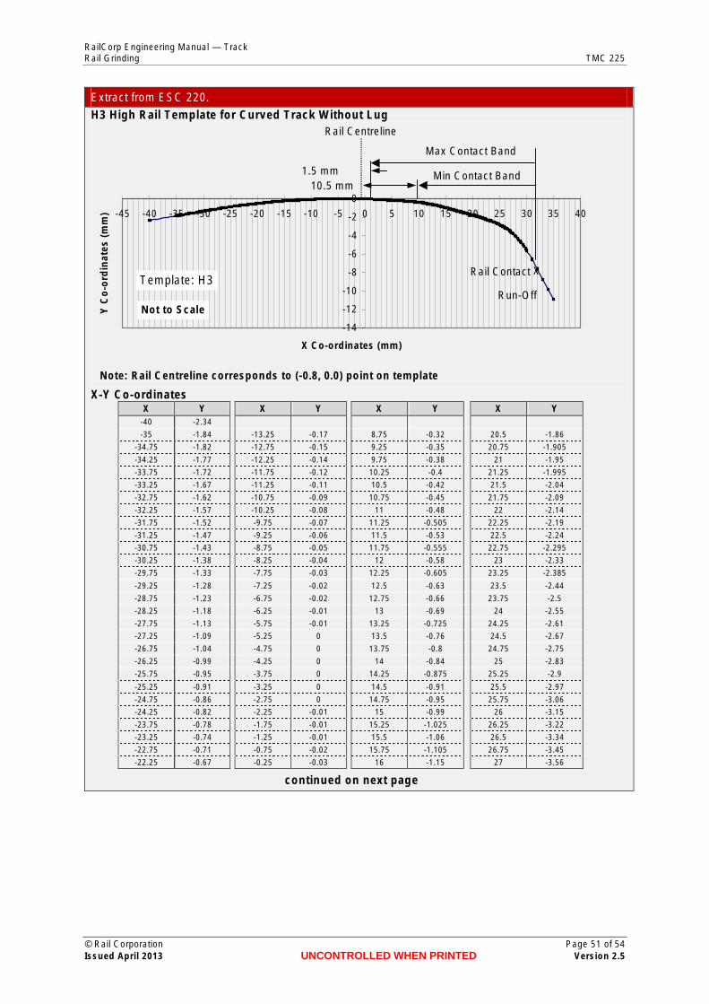
RailCorp Engineering Manual — Track Rail Grinding TMC 225
Y C
o-o
rdin
ates
(m
m)
Extract from ESC 220.
H3 High Rail Template for Curved Track Without Lug Rail Centreline
Max Contact Band
1.5 mm Min Contact Band 10.5 mm
0
-45 -40 -35 -30 -25 -20 -15 -10 -5 0 5 10 15 20 25 30 35 40 -2
-4
-6
-8 XRail Contact Template: H3
-10 Run-Off -12
-14
Not to Scale
X Co-ordinates (mm)
Note: Rail Centreline corresponds to (-0.8, 0.0) point on template
X-Y Co-ordinates X Y X Y X Y X Y
-40 -2.34
-35 -1.84 -13.25 -0.17 8.75 -0.32 20.5 -1.86
-34.75 -1.82 -12.75 -0.15 9.25 -0.35 20.75 -1.905
-34.25 -1.77 -12.25 -0.14 9.75 -0.38 21 -1.95
-33.75 -1.72 -11.75 -0.12 10.25 -0.4 21.25 -1.995
-33.25 -1.67 -11.25 -0.11 10.5 -0.42 21.5 -2.04
-32.75 -1.62 -10.75 -0.09 10.75 -0.45 21.75 -2.09
-32.25 -1.57 -10.25 -0.08 11 -0.48 22 -2.14
-31.75 -1.52 -9.75 -0.07 11.25 -0.505 22.25 -2.19
-31.25 -1.47 -9.25 -0.06 11.5 -0.53 22.5 -2.24
-30.75 -1.43 -8.75 -0.05 11.75 -0.555 22.75 -2.295
-30.25 -1.38 -8.25 -0.04 12 -0.58 23 -2.33
-29.75 -1.33 -7.75 -0.03 12.25 -0.605 23.25 -2.385
-29.25 -1.28 -7.25 -0.02 12.5 -0.63 23.5 -2.44
-28.75 -1.23 -6.75 -0.02 12.75 -0.66 23.75 -2.5
-28.25 -1.18 -6.25 -0.01 13 -0.69 24 -2.55
-27.75 -1.13 -5.75 -0.01 13.25 -0.725 24.25 -2.61
-27.25 -1.09 -5.25 0 13.5 -0.76 24.5 -2.67
-26.75 -1.04 -4.75 0 13.75 -0.8 24.75 -2.75
-26.25 -0.99 -4.25 0 14 -0.84 25 -2.83
-25.75 -0.95 -3.75 0 14.25 -0.875 25.25 -2.9
-25.25 -0.91 -3.25 0 14.5 -0.91 25.5 -2.97
-24.75 -0.86 -2.75 0 14.75 -0.95 25.75 -3.06
-24.25 -0.82 -2.25 -0.01 15 -0.99 26 -3.15
-23.75 -0.78 -1.75 -0.01 15.25 -1.025 26.25 -3.22
-23.25 -0.74 -1.25 -0.01 15.5 -1.06 26.5 -3.34
-22.75 -0.71 -0.75 -0.02 15.75 -1.105 26.75 -3.45
-22.25 -0.67 -0.25 -0.03 16 -1.15 27 -3.56
continued on next page
© Rail Corporation Page 51 of 54 Issued April 2013 UNCONTROLLED WHEN PRINTED Version 2.5

RailCorp Engineering Manual — Track Rail Grinding TMC 225
Extract from ESC 220. X Y X Y X Y X Y
-21.75 -0.63 0.25 -0.04 16.25 -1.19 27.25 -3.69
-21.25 -0.6 0.75 -0.04 16.5 -1.23 27.5 -3.83
-20.75 -0.56 1.25 -0.05 16.75 -1.275 27.75 -3.97
-20.25 -0.53 1.75 -0.07 17 -1.32 28 -4.12
-19.75 -0.5 2.25 -0.08 17.25 -1.355 28.25 -4.28
-19.25 -0.47 2.75 -0.09 17.5 -1.39 28.5 -4.45
-18.75 -0.44 3.25 -0.1 17.75 -1.43 28.75 -4.62
-18.25 -0.41 3.75 -0.12 18 -1.47 29 -4.8
-17.75 -0.38 4.25 -0.14 18.25 -1.505 29.25 -4.99
-17.25 -0.35 4.75 -0.15 18.5 -1.54 29.5 -5.18
-16.75 -0.33 5.25 -0.17 18.75 -1.58 29.75 -5.39
-16.25 -0.3 5.75 -0.19 19 -1.62 30 -5.6
-15.75 -0.28 6.25 -0.21 19.25 -1.66 31 -6.56
-15.25 -0.25 6.75 -0.23 19.5 -1.7 32 -7.64
-14.75 -0.23 7.25 -0.25 19.75 -1.74 33 -8.72
-14.25 -0.21 7.75 -0.27 20 -1.78 34 -9.8
-13.75 -0.19 8.25 -0.3 20.25 -1.82 35 -10.87
Note: The profile has been specified for a free standing rail centreline using the above coordinate system incorporating the rail centreline. Therefore when producing rail profile templates a cant adjustment of 1:20 (2.86°) clockwise rotation must be added so that the profile is referenced perpendicular to the track plane.
© Rail Corporation Page 52 of 54 Issued April 2013 UNCONTROLLED WHEN PRINTED Version 2.5

-12
-10
-8
-6
-4
-2
0
2
-35 -30 -25 -20 -15 -10 -5 0 5 10 15 20 25 30 35
Not to Scale Run Off
Gauge Side
Contact Point
RailCorp Engineering Manual — Track Rail Grinding TMC 225
Extract from ESC 220.
H4 – Modified HR High Rail Template Without Lug, No Rail Cant
-40 40
Y C
o-o
rdin
ates
(m
m)
X Co-ordinates (mm)
X-Y Co-ordinates X Y X Y X Y X Y
-40.00 -2.34 -18.25 -0.41 -0.75 -0.02 16.75 -1.28
-35.00 -1.84 -17.75 -0.38 -0.25 -0.03 17.25 -1.36
-34.75 -1.82 -17.25 -0.35 0.25 -0.04 17.75 -1.43
-34.25 -1.77 -16.75 -0.33 0.75 -0.04 18.25 -1.52
-33.75 -1.72 -16.25 -0.30 1.25 -0.05 18.75 -1.62
-33.25 -1.67 -15.75 -0.28 1.75 -0.07 19.25 -1.72
-32.75 -1.62 -15.25 -0.25 2.25 -0.08 19.75 -1.82
-32.25 -1.57 -14.75 -0.23 2.75 -0.09 20.25 -1.89
-31.75 -1.52 -14.25 -0.21 3.25 -0.10 20.75 -1.99
-31.25 -1.47 -13.75 -0.19 3.75 -0.12 21.25 -2.10
-30.75 -1.43 -13.25 -0.17 4.25 -0.14 21.75 -2.23
-30.25 -1.38 -12.75 -0.15 4.75 -0.18 22.25 -2.35
-29.75 -1.33 -12.25 -0.14 5.25 -0.22 22.75 -2.47
-29.25 -1.28 -11.75 -0.12 5.75 -0.25 23.25 -2.63
-28.75 -1.23 -11.25 -0.11 6.25 -0.27 23.75 -2.80
-28.25 -1.18 -10.75 -0.09 6.75 -0.30 24.25 -2.97
-27.75 -1.13 -10.25 -0.08 7.25 -0.34 24.75 -3.14
-27.25 -1.09 -9.75 -0.07 7.75 -0.37 25.25 -3.33
-26.75 -1.04 -9.25 -0.06 8.25 -0.39 25.75 -3.52
-26.25 -0.99 -8.75 -0.05 8.75 -0.43 26.25 -3.68
-25.75 -0.95 -8.25 -0.04 9.25 -0.46 26.75 -3.87
-25.25 -0.91 -7.75 -0.03 9.75 -0.50 27.25 -4.04
-24.75 -0.86 -7.25 -0.02 10.25 -0.55 27.75 -4.25
-24.25 -0.82 -6.75 -0.02 10.75 -0.60 28.25 -4.53
-23.75 -0.78 -6.25 -0.01 11.25 -0.65 28.75 -4.74
-23.25 -0.74 -5.75 -0.01 11.75 -0.69 29.25 -5.01
-22.75 -0.71 -5.25 0.00 12.25 -0.74 29.65 -5.31
-22.25 -0.67 -4.75 0.00 12.75 -0.77 30.00 -5.60
-21.75 -0.63 -4.25 0.00 13.25 -0.82 31.00 -6.56
-21.25 -0.60 -3.75 0.00 13.75 -0.86 32.00 -7.64
-20.75 -0.56 -3.25 0.00 14.25 -0.91 33.00 -8.72
-20.25 -0.53 -2.75 0.00 14.75 -0.98 34.00 -9.80
-19.75 -0.50 -2.25 -0.01 15.25 -1.03 35.00 -10.87
-19.25 -0.47 -1.75 -0.01 15.75 -1.11
-18.75 -0.44 -1.25 -0.01 16.25 -1.19
© Rail Corporation Page 53 of 54 Issued April 2013 UNCONTROLLED WHEN PRINTED Version 2.5

RailCorp Engineering Manual — Track Rail Grinding TMC 225
Extract from ESC 220.
H4 – Modified HR High Rail Template With Lug, No Rail Cant X
Co
-ord
inat
es (
mm
)
2
0 -40 -35 -30 -25 -20 -15 -10 -5 0 5 10 15 20 25 30 35 40
-2
-4
-6 Gauge Side
-8
-10
-12
-14
Not to Scale -16
-18
-20
X-Y Co-ordinates X Y X Y X Y X Y
-40.00 -2.34 -17.75 -0.38 0.25 -0.04 18.25 -1.52
-35.00 -1.84 -17.25 -0.35 0.75 -0.04 18.75 -1.62
-34.75 -1.82 -16.75 -0.33 1.25 -0.05 19.25 -1.72
-34.25 -1.77 -16.25 -0.30 1.75 -0.07 19.75 -1.82
-33.75 -1.72 -15.75 -0.28 2.25 -0.08 20.25 -1.89
-33.25 -1.67 -15.25 -0.25 2.75 -0.09 20.75 -1.99
-32.75 -1.62 -14.75 -0.23 3.25 -0.10 21.25 -2.10
-32.25 -1.57 -14.25 -0.21 3.75 -0.12 21.75 -2.23
-31.75 -1.52 -13.75 -0.19 4.25 -0.14 22.25 -2.35
-31.25 -1.47 -13.25 -0.17 4.75 -0.18 22.75 -2.47
-30.75 -1.43 -12.75 -0.15 5.25 -0.22 23.25 -2.63
-30.25 -1.38 -12.25 -0.14 5.75 -0.25 23.75 -2.80
-29.75 -1.33 -11.75 -0.12 6.25 -0.27 24.25 -2.97
-29.25 -1.28 -11.25 -0.11 6.75 -0.30 24.75 -3.14
-28.75 -1.23 -10.75 -0.09 7.25 -0.34 25.25 -3.33
-28.25 -1.18 -10.25 -0.08 7.75 -0.37 25.75 -3.52
-27.75 -1.13 -9.75 -0.07 8.25 -0.39 26.25 -3.68
-27.25 -1.09 -9.25 -0.06 8.75 -0.43 26.75 -3.87
-26.75 -1.04 -8.75 -0.05 9.25 -0.46 27.25 -4.04
-26.25 -0.99 -8.25 -0.04 9.75 -0.50 27.75 -4.25
-25.75 -0.95 -7.75 -0.03 10.25 -0.55 28.25 -4.53
-25.25 -0.91 -7.25 -0.02 10.75 -0.60 28.75 -4.74
-24.75 -0.86 -6.75 -0.02 11.25 -0.65 29.25 -5.01
-24.25 -0.82 -6.25 -0.01 11.75 -0.69 29.65 -5.31
-23.75 -0.78 -5.75 -0.01 12.25 -0.74 30.10 -5.78
-23.25 -0.74 -5.25 0.00 12.75 -0.77 30.61 -6.40
-22.75 -0.71 -4.75 0.00 13.25 -0.82 31.05 -6.86
-22.25 -0.67 -4.25 0.00 13.75 -0.86 31.71 -7.56
-21.75 -0.63 -3.75 0.00 14.25 -0.91 32.37 -8.37
-21.25 -0.60 -3.25 0.00 14.75 -0.98 33.05 -9.32
-20.75 -0.56 -2.75 0.00 15.25 -1.03 33.73 -10.48
-20.25 -0.53 -2.25 -0.01 15.75 -1.11 36.28 -10.35
-19.75 -0.50 -1.75 -0.01 16.25 -1.19 36.45 -13.71
-19.25 -0.47 -1.25 -0.01 16.75 -1.28 35.00 -13.77
-18.75 -0.44 -0.75 -0.02 17.25 -1.36 35.25 -18.76
-18.25 -0.41 -0.25 -0.03 17.75 -1.43
© Rail Corporation Page 54 of 54 Issued April 2013 UNCONTROLLED WHEN PRINTED Version 2.5