title of the project: home security system using …mr.arijit ghosh ----- mr.arijit ghosh applied...
TRANSCRIPT

TITLE OF THE PROJECT:
Home Security System using Raspberry Pi
By
Sangbit Chakraborty (University Roll No. 11705515038 )
Ankur Roy (University Roll No. 11705515005 )
Satwik Poddar (University Roll No. 11705515040 )
Soumya Dhali (University Roll No. 11705515043 )
Under Supervision of
Mr. Arijit Ghosh
Project report submitted in partial fulfillment for
the Degree of B. Tech in Applied Electronics &
Instrumentation Engineering under Maulana Abul
Kalam Azad University of Technology
DEPARTMENT OF APPLIED ELECTRONICS &
INSTRUMENTATION ENGINEERING,
RCC INSTITUTE OF INFORMATION TECHNOLOGY,
CANAL SOUTH ROAD, BELIAGHATA, KOLKATA – 700015,
May,2019


ACKNOWLEDGEMENT
It is a great privilege for us to express our profound gratitude to our teacher Mr.Arijit Ghosh,
Applied Electronics &Instrumentation Engineering, RCC Institute of Information Technology,
for his constant guidance, valuable suggestions, supervision and inspiration throughout the
course work without which it would have been difficult to complete the work within scheduled
time.
We would like to express our gratitude towards all the faculty members for his/her kind co-
operation and encouragement which helped us in completion of this project.
We are also indebted to the Head of the Department, Applied Electronics & Instrumentation
Engineering, RCC Institute of Information Technology for permitting us to pursue the project.
We would like to take this opportunity to thank all the respected teachers of this department for
being a perennial source of inspiration and showing the right path at the time of necessity.
----------------------------------
Sangbit Chakraborty
(11705515038)
----------------------------------
Satwik Poddar
(11705515040)
----------------------------------
Ankur Roy
(11705515005)
----------------------------------
Soumya Dhali
(11705515043)


RCC INSTITUTE OF INFORMATION TECHNOLOGY CANAL SOUTH ROAD, BELIAGHATA, KOLKATA – 700 015 PHONE : 2323 2463 FAX : (033)2323 4668
E-mail : [email protected] Website : www.rcciit.org
CERTIFICATE OF APPROVAL
The project report titled “Home Security System Using Raspberry pi” prepared by Sangbit
Chakraborty(11705515038),Satwik Poddar(11705515040),Ankur Roy(11705515005) and
Soumya Dhali(11705515043) is hereby approved and certified as a creditable study in
technological subjects performed in a way sufficient for its acceptance for partial fulfilment of
the degree for which it is submitted.
It is to be understood that by this approval, the undersigned do not, necessarily endorse or
approve any statement made, opinion expressed or conclusion drawn therein, but approve the
project only for the purpose for which it is submitted.
-----------------------------------
Mr.Arijit Ghosh
Applied Electronics & Instrumentation
Engineering
--------------------------------------
Examiner
--------------------------------------
Examiner

RCC INSTITUTE OF INFORMATION TECHNOLOGY CANAL SOUTH ROAD, BELIAGHATA, KOLKATA – 700 015 PHONE : 2323 2463 FAX : (033)2323 4668
E-mail : [email protected] Website : www.rcciit.org
RECOMMENDATION
We hereby recommend that the project report titled “Home Security System Using Raspberry pi”
prepared by Sangbit Chakraborty(11705515038),Satwik Poddar(11705515040),Ankur
Roy(11705515040) and Soumya Dhali(11705515043) be accepted in partial fulfillment of the
requirement for the Degree of Bachelor of Technology in Applied Electronics & Instrumentation
Engineering, RCC Institute of Information Technology.
-------------------------------------
Mr.Arijit Ghosh
--------------------------------------
Mr.Arijit Ghosh
Applied Electronics & Instrumentation Engineering

ABSTRACT
With the advancement of modern technologies areas related to robotics and computer vision, real
time image processing has become a major technology under consideration. So here a try has
been made for a novel approach for capturing images from the Pi Camera in real time
environment and process them as we are required. This project portrays an machine learning
approach for face recognization to accomplish this process very quick with high identification
rates using OpenCV. Here in this project depicts a basic and simple equipment execution of face
location framework utilizing Raspberry Pi, which itself is a minicomputer of a small estimate
and is of a low cost. The framework is modified utilizing Python programming language. The
destinations of the face recognization are to recognize appearances and its spatial area in any
pictures or recordings .The proposed framework distinguishes the faces present in a grey scale
and colored image. This project center around usage of face detection framework for human
recognizable proof in light of OpenCV library with python. Here in this project the idea of
identification has been built up by composing distinguishable code for dataset generator, trainer
and indicator. Effectiveness of the framework is examined by ascertaining the Face
recognization rate for every one of the database. The outcomes uncover that the proposed
framework can be utilized for face detection even from low quality pictures and shows incredible
execution level. At last the data that will be shown alongside recognized photograph has been put
away on database. This concept has a higher scope on security and surveillance projects and
various operation.

LIST OF FIGURES
Figure Page no
Figure 1: Block Diagram 9
Figure 2: Circuit Diagram 10
Figure 3: Raspberry Pi 11
Figure 4: Raspberry Pi Pin diagram 12
Figure 5: Raspberry Pi Pin diagram(2) 12
Figure 6: Raspberry Pi camera 14
Figure 7: 2 channel relay 15
Figure 8: Schematic Diagram of the Relay 16
Figure 9: 2 channel relay with Raspberry Pi 17
Figure 10: DC Motor 18
Figure 11: LED 19
Figure 12: Installation of Raspbian 20
Figure 13: Installation of OpenCV 25
Figure 14: Edge features 27
Figure 15: Line Features 28
Figure 16: Center surround features 28
Figure 17: Special diagonal line features 29
Figure 18: Setup of the whole system for face recognition 30
Figure 19: Connection of the PC and Pi camera with Raspberry Pi 31
Figure 19(a): HDMI cable and Pi camera connection with Raspberry Pi 32

Figure 20: Output of Face Recognization 33
Figure 20(a): Output of the Face Rcognization 34
Figure 20(b): Outcome of the face recognization process 35

CONTENTS
Chapters Page No
Chapter 1: Introduction 1
Chapter 2: Literature Review
2.1: Earlier Developments 3
2.2: Recent Developments 4
2.3: Face Recognization 6
Chapter 3: Overview of the Project
3.1 Block Diagram 9
3.2 Hardware equipments 9
3.3 Circuit Diagram 10 10
Chapter 4: Component Description
4.1: Raspberry Pi 11
4.2 Raspberry Pi Camera 14
4.3 2 channel Relay 15
4.3.1 2 Channel Relay with Raspberry Pi 17
4.4 DC Motor 18
4.5 LED 19
Chapter 5: Methodology
5.1 Installing Raspbian on the Raspberry Pi 20
5.2 Installation of OpenCV 21
5.3 Face Recognization 24
5.4 Haar Cascade Classifier Algorithm 26

Chapter6: Results and Discussion 30
6.1 Face Recognization 33
Chapter 7: Conclusion and Future Works 37
Chapter 8: References 39
Chapter 9: Datasheets 42

INTRODUCTION: CHAPTER 1
Page | 1
INTRODUCTION
Home automation alludes to the use of computer applications and information technology for
control of home and residential appliances. Its application changes from basic remote control of
lighting to complex microcontroller based systems including changing degrees of insight and
automation. Home automation results in ease of work, increased efficiency, and security benefits
prompting improved personal satisfaction. The prevalence of system empowered home
automation has been expanding incredibly as of late because of straightforwardness and a lot
higher affordability. Also, with the fast development of the Internet, there is the potential for the
remote control and checking of such network enabled appliances. Notwithstanding, the new and
energizing chances to expand the availability of gadgets inside the home is the end goal of home
automation. Modeling of a home automation system for controlling all the various devices in
Remote locations can be achieved through a variety of communication options such as wireless
LAN technologies, dial-up modems, satellite communication, cellular network, Internet and so
on. The main virtue of home automation can be stated as its security facilities where one can be
notified and one can be alarmed by this home automation if there is any threat caused to
someone’s privacy. Home automation enables human beings to take advantage of high-tech
functionality that was almost impossible to visualize a few years back. The convenience factor
here is huge. Having the capacity to keep the majority of the automation inside home associated
through one interface is a huge step forward towards innovation and home automation.
Theoretically, all one has to do is simply figure out how to utilize one application on a cell phone
and tablet, and one will have the capacity to take advantage of incalculable capacities and
gadgets all through the home. This reduces the expectation to absorb information for new clients,
makes it simpler to get to the usefulness someone really need for their home. Smart home
systems tend to be wonderfully flexible when it comes to the accommodation of new devices and
appliances and other technology. No matter how state-of-the-art your appliances seem today,
there will be newer, more impressive models developed as time goes on. Beyond that, you’ll
probably add to the suite of devices as it will replace the older ones or discover new technology
to accompany indoor and outdoor spaces. Being able to integrate these newcomers seamlessly
will make everyones job as a homeowner much easier, and allows to keep upgrading to the latest
lifestyle technology. Home automation frameworks can associate motion detectors, surveillance
cameras, automated entryway locks, and other substantial safety efforts all through the home so

INTRODUCTION: CHAPTER 1
Page | 2
one can enact them from one cell phone before making a beeline for bed. It will provide security
cautions on different gadgets relying upon the time of day an alarm goes off, and watch activities
continuously whether someone is in the house or most of the way around the world. A very
important part of this security virtue of home automation is keeping surveillance through
cameras and survilliance on the entryway automated and which can be only open by certain
identities which are granted permission to enter. For this doing face recognization where if the
face is recognized then the door will open otherwise not. In this proposed scheme face
recognization which generally involves two stages which are face detection and then face
recognization is done. Face Detection where the picture is searched to feed a face, then the
picture is processed to crop and extract the person’s face for easier recognization. Face
Recognization is the part where that detected and processed face is compared to a database of
known faces, to decide who that person is. Here face detection is performed on Intel’s open
source framework called OpenCV. OpenCV (Open Source Computer Vision) is a library that can
be imported in almost all computer languages like python, C, Java etc. python. Raspberry pi-cam
has been used to capture the picture of the faces that we are going to store in the database. Here
in this proposed scheme one will basically go through three stages which are face detection, data
gathering(where we will click picture of the faces of the respective identities) and the final stage
is going to be the face recognization part which will match the live faces with the pictures of the
faces in the database and give us the identification details of the given entity and work further for
extra requirements. If the matching index is 50% or more then only it can be said that it is a
successful facial recognization process. OpenCV has got lot of algorithms but in this particular
project. Here Haar-Cascade algorithm Haar Cascade Algorithm has been used mainly. This
whole setup is done on the operating system of Raspberry Pi which is known as Raspbian.
Python has been used here as the platform to perform the functions and keeping OpenCV the
main domain. Finally home automation can be summed up as the most convenient form of
modern day technology. Home automation is actually a mixture of a lot of virtues coming
together like safety, control, comfort, convinience and most importantly peace of mind. This
form is a very flexible form of technology which is growing in the market very rapidly and is on
the upsurge for being a game changer in the field of modern day automation.

LITERATURE REVIEW: CHAPTER 2
3 | P a g e
CHAPTER 2: LITERATURE REVIEW
2.1 EARLIER DEVELOPMENTS:
The idea of home automation has been revolving around for around for some time. It’s very
recent that actual smart homes have come into existence. Keeping in mind the advantages related
to home automation research and development projects already started from a long time back but
due to the absence of standard networking of the home appliances nobody could move forward
with this concept. The major roadblock was removed in 1992 with the development of the
consumer electronic bus by Electronics Industries Association of America. The CEBus standard
includes specification for a layered network architecture based on open system interconnection
model with network layer protocols for the physical, Data Link, Network layer and application
layer [1]. A proposed scheme by Cross & Douligeris states that fiber optics might be the best
medium for home automation network because with fiber, the limitations of the home
automation system can be reduced and capabilities can be increased to include many more
functions, leading to complete home integration. They observed that although CEBus includes
fiber optics as one of the physical media but it is not specifying the configuration of the fiber
optic network. After that they designed a fiber optics network which offered various advantages
such as (i) increased bandwidth, (ii) immunity to electromagnetic noise, (iii) ease of installation,
and (iv) safety from electric shock hazards. There were a few drawbacks as well that the cost was
high and as fiber optics cannot carry direct current they had to use an alternate source of energy
[2-3]. In early 1990s, the consumer electronics devices was evolving into digital format,
henceforth the need was felt to interconnect these home appliances through digital links to
preserve the fidelity of information transmitted. Chen proposed a home automation network
which will serve the above purpose. Other than the digital link main feature of the proposed
home automation network was the Digital access system which due to which the home
automation network could communicate and with the outside world also. Chen researched the
use of IEEE 1394 for the proposed network as it could handle both data and isochronous traffic
well at a data rate above 100 Mbps [4]. Fujieda sensed for thriving and achieving complete
marketability. Home networks should be installed easily which will require network buildup
without extra wiring. Therefore he proposed the scheme for wireless media in home networks
and named it as wireless home networks. Fujieda suggested the use of 400MHz special low

LITERATURE REVIEW: CHAPTER 2
4 | P a g e
power band for wireless home networks. He developed a small and low power microwave oven,
air conditioner and washing machines, Bluetooth access point and home terminal in a home. All
appliances had the Bluetooth unit embedded within them and wee connected to internet [5]. In
2005 Hayong Oh and others, mentioned the importance of energy efficiency for the routing
scheme of the sensors placed at home. In the upcoming automated home, sensors are required to
be placed everywhere in the house which will collect various physical data such as temperature,
humidity, and light to provide information to various appliances. The authors discussed that in
the conventional sensor routing scheme every sensor node detects an event and then broadcasts
the event to all sensor nodes within one hop range from where all the nodes broadcast the
message to the next nodes. This process is repeated until the event reaches the base station. This
scheme generally cause drainage of battery power and the batteries have got limited power so the
routing scheme needs to efficient enough for successful implementation of home networking.
Henceforth they advised a new sensor routing scheme for home automation networks and called
it as RDSR (Relative Direction based Sensor Routing). This scheme divides the home area into
sectors and locates a manager node to each sector. The sensor devices transfer the data to
manager nodes in its sector and then the data is transferred to the base station through the
shortest path of two dimensional coordinates resulting in an energy efficient scheme [6]. In 2006
Mario Kolberg and Evan H.Magill mentioned the control of complex networked appliances.
Presently computer interface is most used to configure and remotely control these appliances.
However the authors discussed that this will be unsuitable for the target audience who are not
that much familiar with the use of computers. Therefore they proposed Anoto-enabled pen and
paper as a suitable alternative as users are highly familiar with pen and paper and they will find it
suitable for control. In the suggested system data is transferred to the service provider through
Bluetooth communication and mobile processed and sent to the user’s home. Using this approach
appliance can be controlled in the home and outside the home [7].
2.2 RECENT DEVELOPMENTS:
In recent years the Internet of Things (IOT) have enabled innovation to make daily lives easier
and comfortable. From refrigerators, to apparatuses, to home security and many others can be
controlled with smart home innovation. When home devices are remotely controlled from
anywhere irrespective of anything through internet it becomes a important virtue of the IoT

LITERATURE REVIEW: CHAPTER 2
5 | P a g e
(Internet of Things). Security and living greener are the main features of the present homes.
Current patterns in home automation includes remotely controlled appliances and computerized
gadgets, portable/email/content warnings, and remote video observation Sensors are the most
important part of this home automation system as it acts as the eyes of the system. There are
sensors for an extensive variety of uses, for example, measuring temperature, dampness, light,
fluid, and gas and recognizing development or commotion. In case of Java Based Home
Automation System the World Wide Web is used by the home appliances to control and monitor
then the software engine is written in Java code that can be portable and also can be used on any
platform. The embedded system board is connected to the pc home server and serves the java
pages and java beans [8]. In case of the Integrated Residential Gateway Controller for Home
Energy Management System, high performance is derived from compact OS and to reduce the
memory space than the three steps plug & player mechanism is used for reducing installation
engineering [9]. In case of the Remote Controller for Home and Office Appliances by Telephone,
the home based design and the development of the phone based remote controller for the home
and office automation, in this advanced technique the remote controller is used for time and
energy consuming [10]. The verification of the proposed algorithm, several LED’s were used to
indicate the proper execution. The Rpi has received an email through the user from a system
connected to the internet. Gmail has been used in order to conduct mail communication. The
corresponding results were generated by a series of e-mail communication. For example an E-
mail sent as “ON=1 ON Time=7:00. OFF Time=8:00 to the RPi account from the user account.
The algorithm that is used starts its process by scanning the mail [11]. According to R.A.
Ramlee, smart home system via Wireless Bluetooth is the is the new virtue of this automated
technologies where it is acting as a motivation for disable persons making it possible for them to
carry out the daily activity, safely and comfortably [12]. Girish Birajdar and Shrikant
Mahindrakar have developed a way in to automate home appliances using an Embedded Web
Server combined with a Raspberry Pi. Embedded Web Server (EWS). is the embedded system
which can serve the web documents on request from the client. It generally deals with
management of dynamic content and is very easy to use and operates at a fast speed. EWS design
includes a complete web server with TCP/IP support, running different OS, memory, application
wise [13].

LITERATURE REVIEW: CHAPTER 2
6 | P a g e
Android based home automation makes the system more flexible and provides attractive user
interface compared to other home automation systems. In this system mobile devices are
integrated into home automation systems. A novel architecture for a home automation system is
proposed using the relatively new communication technologies. The system consists of mainly
three components is a Wi-Fi module, raspberry pi board and relay circuits. Wi-Fi is used as the
communication channel between android phone and the raspberry pi board [14].
2.3 FACE RECOGNIZATION:
Face detection is one of the current research topics in the computer vision field. It is very easy
for human beings to detect faces on the other hand it is difficult for computers to detect faces..
The difficulties associated with face detection are variations in scale, pose, orientation, lighting
condition, facial expression etc. Many approaches have been implemented but each has its own
advantages and limitations. The proposed system is relay on the appearance based approach.
Here the face detection is done by extracting facial features like eye feature, bridge of the nose
feature, mouth feature etc. which are present in a grey scale image. These features are
proportional to the change in contrast values between adjacent groups of pixels but not to the
intensity values of a pixel. The features used in this system are named as rectangular features and
are reminiscent of Haar basis functions [15] [16]. The suggested face detection system detects
the faces with low false positive rate. Initially the face detection is done with 10 and 12 stage
detector but it gives poor detection accuracy and high false positive rate. The 14 stage detector
gives good accuracy in face detection and very low false positive rates. The detector works well
on Raspberry Pi with a 5MP camera and detects the faces of captured image with the lowest
resolution of 640x480 and the highest resolution of 2560x1920pixels with acceptable detection
speed [17]. Patel and shah introduced a research on facial feature extraction techniques for
automatic face annotation. A vital role is being played by automatic face annotation role in
multimedia information. The method to identify human faces from image and assign appropriate
human name is known as automatic face annotation. In face annotation face detection and face
recognition are the two most important virtues. An author also discuss the phases of the
automatic face annotation and surveyed various techniques of facial feature extraction [18].
Patoliya and Desai developed ATM Security System using Embedded Linux Platform which is
being based on the face detection system. Raspberry pi is being used for the implementation of
LITERATURE REVIEW: CHAPTER 2
7 | P a g e
this system with the extended capabilities of Computer Vision (OpenCV) software which is used
for Image processing operation. One tine password technique is used in this system which
increases the security of the system. In an unauthorized condition ATM door has been locked
and it’s only when the OTP password is entered my watchman [19]. Heshmat et al. introduced
Face Identification system in Video. An author proposed CIE-Luv color space, facial feature
extraction and variance estimation. In surveillance, human machine interfacing, Database
management system can be implemented and is of great use as it is creating a proper visual
interface here. The experimental results shows the efficiency and the usefulness of the system
where the system can recognize different faces and work accordingly and this one is highly
advantageous due to it high security advantages [20]. Intensive research work and detailed study
on implementation of smart door lock system using GSM network by Jie-Ci Yang [21]. Pi
Camera Module is a add on with Raspberry Pi which acts as a visual interface in case of face
detection or Recognization, This interface uses the dedicated CSI interface, which was designed
especially for interfacing to cameras [22]. An algorithm known as Haar Cascade classifier is used
for detection of the object which it has been trained for, from the source. This proposed system
uses Haar Cascades classifier as a face detection algorithm [23]. Face preprocessing is the
module which lessens the issues that makes the image vague to perceive the face. for example,
less brightness and complexity issues and noise in the picture and ensure the facial highlights
dependably be in a consistent position. In this task we use histogram leveling for face
preprocessing. For proficiency we utilize separate preprocessing which is histogram evening out
for left and right face. So histogram leveling is completed multiple times, right off the bat for the
entire face and the other two for side appearances [24]. For better working, each stage of the
cascade must have a low false negative rate, because if the actual object is classified as a non-
object, then the classification of that branch stops, with no way to correct the mistake made.
However, each stage can have a relatively high false positive rate, because even if the n-th stage
classifies the non-object as actually being the object, then this mistake can be fixed in n+1-the
and subsequent stages of the classifier[25-26]. The purpose or objective of the suggested work is
to implement a working model of a smart door and to give solutions to the problem faced by
people in day to day incidents of burglary or losing the key and also to promote and ignite the
work being done on IOT systems and implementing it with the help of key research areas of
Neural Networks and IoT APIs and protocols[27].

LITERATURE REVIEW: CHAPTER 2
8 | P a g e
After the detailed study of the previous works, here in this proposed scheme developing a home
automation system using a Raspberry Pi with which one will be able to control home appliances
and the most important virtue of this project will be the home surveillance where the face
recognization technology which will be used as a part of security in this project. The main
platform which is being used is OpenCV which is a open source computer vision library a part of
python and will be used in Python.

OVERVIEW OF THE PROJECT: CHAPTER 3
9 | P a g e
CHAPTER 3: OVERVIEW OF THE PROJECT 3.1 BLOCK DIAGRAM:
3.2 HARDWARE REQUIREMENTS:
RASPBERRY Pi
RASPBERRY Pi CAMERA
4 CHANNEL 2 SLOT RELAY
DC MOTOR
LED
BREADBOARD
CONNECTING WIRES
MINIATURE DOOR
Figure 1: Block Diagram
Pi Camera
Raspberry Pi
Relay
LED
DC Motor
Miniature Door

OVERVIEW OF THE PROJECT: CHAPTER 3
10 | P a g e
3.3 CIRCUIT DIAGRAM:
Here one can see that the Pi camera is attached to the camera slot and the DC motor and Relay is
attached to the GPIO pins of the Raspberry Pi. As it is a two channel relay so it is connected to
the LED and the DC motor which helps in driving the DC motor.Here the DC motor drives a
miniature door which is being used for a door locking system for surveillance purposes. The door
only opens after a successful recognization process, when the face is stored previously in the
database and that image has got the access to open the door then it will work otherwise it won’t
open.
Figure 2: Circuit diagram
Raspberry pi
Camera
slot
Pi camera
GPIO
DC Motor
Relay
LED

COMPONENT DESCRIPTION: CHAPTER 4
11 | P a g e
CHAPTER 4: COMPONENT DESCRIPTION
4.1 RASPBERRY Pi:
In the above figure no.3 the Raspberry Pi is a low priced, small sized computer that plugs into a
computer monitor or TV, and uses a normal peripherals like keyboard and mouse. It is a capable
little device that enables people of all ages to explore computing, and to learn how to program in
languages like Scratch and Python. It’s capable of doing everything you’d expect a desktop
computer to do, from browsing the internet and playing high-definition video, to making
spreadsheets, word-processing, and playing games. The Raspberry Pi was first launched in 2012,
and there have been a few changes and variations performed from that point forward. The first Pi
had a single core 700MHz CPU and simply 256MB RAM, and the most recent model has a
quad-core 1.4GHz CPU with 1GB RAM.All over the world, individuals use Raspberry Pi to get
the skills of programming abilities, , do home automation, and even use them in modern
applications.The Raspberry Pi works in the open source environment: it runs Linux (diverse
distribution), and its principle supported working system, Raspbian, is open source and runs a
suite of open source programming. The Raspberry Pi Foundation adds to the Linux part and
Figure3:Raspberry Pi

COMPONENT DESCRIPTION: CHAPTER 4
12 | P a g e
different other open source extends just as releasing its very own lot programming as open
source.
Here Raspberry pi is being used as a main controller to derive other features like face
recognization and detection which we are doing in our project.
Figure 4: Pin diagram Raspberry Pi
Figure 5: Pin Diagram of Raspberry Pi(2)

COMPONENT DESCRIPTION: CHAPTER 4
13 | P a g e
A powerful feature of the Raspberry Pi is the row of GPIO (general-purpose input/output) pins
along the top edge of the board. A 40-pin GPIO header is found on all current Raspberry Pi
boards.
Voltages:
Two 5V pins and two 3V3 pins are present on the board, as well as a number of ground pins
(0V), which are unconfigurable. The remaining pins are all general purpose 3V3 pins, meaning
outputs are set to 3V3 and inputs are 3V3-tolerant.
Outputs:
A GPIO pin designated as an output pin can be set to high (3V3) or low (0V).
Inputs:
A GPIO pin designated as an input pin can be read as high (3V3) or low (0V). This is made
easier with the use of internal pull-up or pull-down resistors. Pins GPIO2 and GPIO3 have fixed
pull-up resistors, but for other pins this can be configured in software. The GPIO pins can be
used for other functions also. Some are available on all pins and others on some specific pins.
PWM (pulse-width modulation)
-Software PWM available on all pins
-Hardware PWM available on GPIO12, GPIO13, GPIO18, GPIO19
SPI
-SPI0: MOSI (GPIO10); MISO (GPIO9); SCLK (GPIO11); CE0 (GPIO8), CE1 (GPIO7)
-SPI1: MOSI (GPIO20); MISO (GPIO19); SCLK (GPIO21); CE0 (GPIO18); CE1 (GPIO17);
I2C
-Data: (GPIO2); Clock (GPIO3)
-EEPROM Data: (GPIO0); EEPROM Clock (GPIO)
Serial
-TX (GPIO14); RX (GPIO15)

COMPONENT DESCRIPTION: CHAPTER 4
14 | P a g e
4.2 RASPBERRY Pi CAMERA:
The Pi camera comes with a flex cable. The flex cable is inserted into the connector which is
located between the Ethernet and HDMI port with the silver connectors facing the HDMI port.
The flex cable connector is opened by pulling the tabs on the top of the connector upwards then
towards the Ethernet port. The flex cable then is inserted firmly into the connector. The top part
of the connector then is pushed towards the HDMI connector and down, while the flex cable is
held in place. Here the Pi camera is being utilized for the face detection and the face
recognization process where firstly are captured and stored it in the database using python and
then again using the camera while the automation and the surveillance part.
Figure 6: Raspberry Pi Camera

COMPONENT DESCRIPTION: CHAPTER 4
15 | P a g e
4.3 TWO CHANNEL RELAY:
This is a LOW Level 5V 2-channel relay interface board, and each channel needs a 15-20mA
driver current. It is used to control various appliances and equipment with large current. It is
equipped with high-current relays that work under AC250V 10A or DC30V 10A. It has a
standard interface that can be controlled directly by microcontroller. Relay is being used here as
a driver circuit to drive other appliances through the relay.
FEATURES:
Relay maximum output: DC 30V/10A, AC 250V/10A.
2 Channel Relay Module with Optocoupler LOW Level Trigger expansion board, which
is perfect with arduino.
Figure 7: 2 channel Relay
COMPONENT DESCRIPTION: CHAPTER 4
16 | P a g e
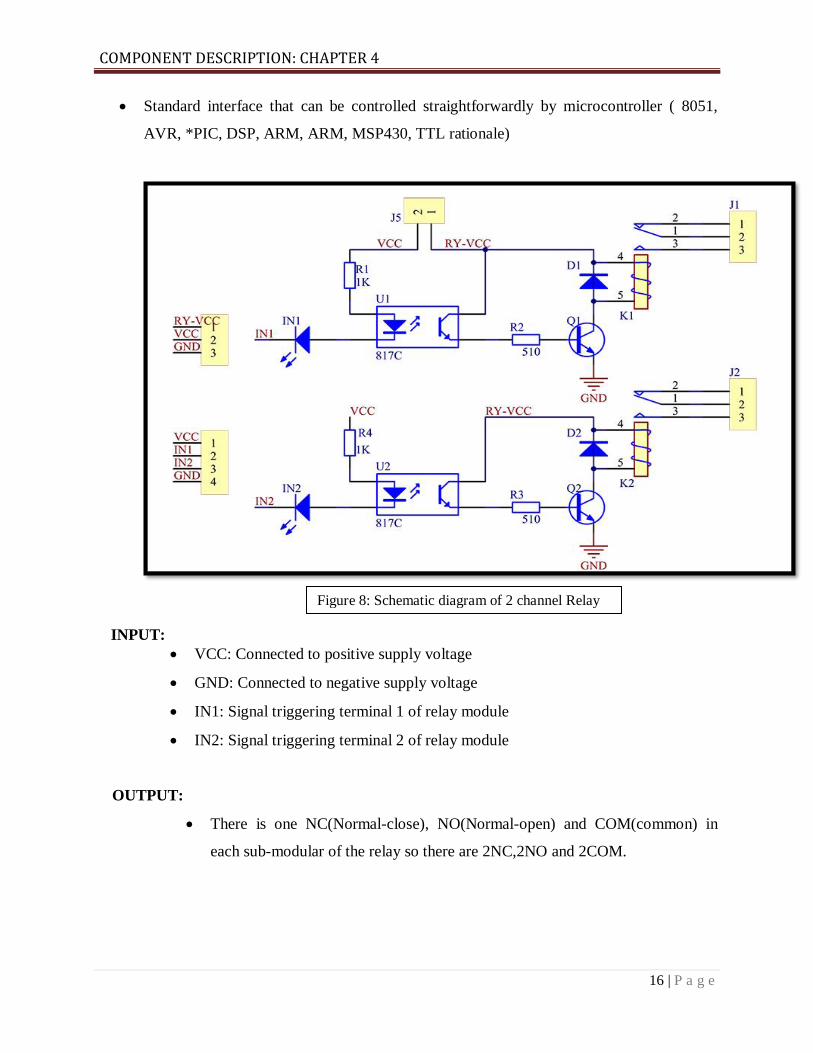
Standard interface that can be controlled straightforwardly by microcontroller ( 8051,
AVR, *PIC, DSP, ARM, ARM, MSP430, TTL rationale)
INPUT:
VCC: Connected to positive supply voltage
GND: Connected to negative supply voltage
IN1: Signal triggering terminal 1 of relay module
IN2: Signal triggering terminal 2 of relay module
OUTPUT:
There is one NC(Normal-close), NO(Normal-open) and COM(common) in
each sub-modular of the relay so there are 2NC,2NO and 2COM.
Figure 8: Schematic diagram of 2 channel Relay
COMPONENT DESCRIPTION: CHAPTER 4
17 | P a g e
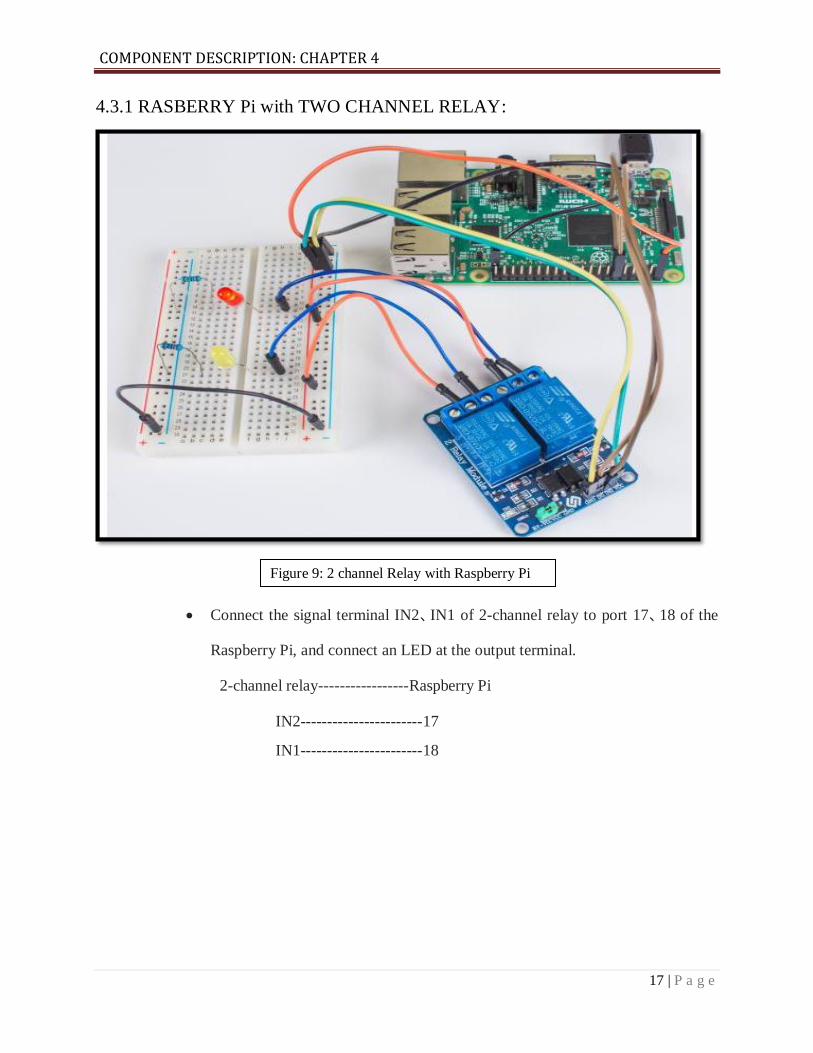
4.3.1 RASBERRY Pi with TWO CHANNEL RELAY:
Connect the signal terminal IN2、IN1 of 2-channel relay to port 17、18 of the
Raspberry Pi, and connect an LED at the output terminal.
2-channel relay-----------------Raspberry Pi
IN2-----------------------17
IN1-----------------------18
Figure 9: 2 channel Relay with Raspberry Pi

COMPONENT DESCRIPTION: CHAPTER 4
18 | P a g e
4.4 DC MOTOR:
A DC motor is a class of rotary electrical equipment which converts direct current electrical
energy into mechanical energy. The most common types depend on the forces produced by
magnetic fields. Almost all types of DC motors have some internal mechanism, either
electromechanical or electronic, which periodically changes the direction of current flow in part
of the motor. A coil of wire with a current running through it generates an electromagnetic field
aligned with the center of the coil. One can change the direction and the magnitude of the
magnetic field by changing the direction and magnitude of the current flowing through it. In this
proposed scheme the DC motor is connected to the relay and drives the miniature door after
successful recognization process.
Figure 10: DC Motor

COMPONENT DESCRIPTION: CHAPTER 4
19 | P a g e
4.5 LED(Light Emitting Diode):
A light-emitting diode (LED) is a semiconductor light source that emits light when current flows
through it. Electrons in the semiconductor recombine with electron holes, releasing energy in the
form of photons. Here the light emitting diode is used just post face recognization where it will
indicate whether the face is recognized. If the face is recognized the LED (Light Emitting Diode)
will glow otherwise it will not glow which will in turn unlock the door.
Figure 11: LED (Light Emitting Diode)
METHODOLOGY: CHAPTER 5
20 | P a g e
METHODOLOGY
5.1 Installing Raspbian on the Raspberry Pi:
Installing Raspbian on the Raspberry Pi is really clear. Raspbian will be downloaded and writing
the disc image to a micro SD card, at that point booting the Raspberry Pi to that microSD card.
For this undertaking, one needs a microSD card (with no less than 8 GB), a PC with a space for
it, and, obviously, a Raspberry Pi and fundamental peripherals (a mouse, console, screen, and
power source). This isn't the main strategy for introducing Raspbian (more on that in a minute),
yet it's a valuable method to learn on the grounds that it can likewise be utilized to introduce
such a significant number of other working projects on the Raspberry Pi. When one realizes how
to compose a circle picture to a microSD card, we open up a great deal of alternatives for
Raspberry Pi projects.
Step1: Download the Raspbian
Turn on the PC and download the Raspbian disc image. One can locate the most recent variant of
Raspbian on the Raspberry Pi Foundation's site here. It will take some time, particularly in the
event when one intends to utilize the conventional download alternative as opposed to the other
download sources. It can without much take a stretch of half hour or more to download.
Step2: Unzip the file
The Raspbian disc image is compressed, so it should be unzipped. The file uses the ZIP64
format, so depending on how current built-in utilities are, one needs to use certain programs to
unzip it. Linux users will use the appropriately named Unzip.
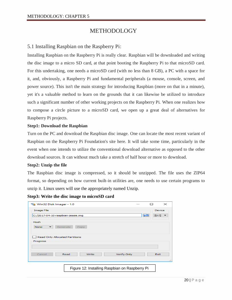
Step3: Write the disc image to microSD card
Figure 12: Installing Raspbian on Raspberry Pi

METHODOLOGY: CHAPTER 5
21 | P a g e
One has to pop the microSD card into our computer and write the disc image to it. The process of
actually writing the image will be slightly different across these programs, but it’s pretty self-
explanatory no matter what is being used. Each of these programs will have us select the
destination and the disc image (the unzipped Raspbian file). Choose, double-check, and then
button to write.
Step 4: Put the microSD card in your Pi and boot up
When the disc image has been kept in touch with the microSD card, it is prepared to go. Put that
microSD into your Raspberry Pi, plug in the peripherals and power source. The present release to
Raspbian will boot straightforwardly to the desktop. Our default credentials are username pi and
password raspberry.
5.2 Installation of OpenCV:
Step1: The first thing to do is to expand our file system to include all available space on our
micro-SD card.
sudo raspi-config
Step2 (install dependencies): The first step is to update and upgrade any existing packages.
Step3: Download the OpenCV source code
After having the dependencies installed we will now grab the 3.3.0 archive of OpenCV from the
official OpenCV repository
sudo raspi-config
sudo apt-get update && sudo apt-get upgrade.
cd ~
wget -O opencv.zip https://github.com/Itseez/opencv/archive/3.3.0.zip
unzip opencv.zip

METHODOLOGY: CHAPTER 5
22 | P a g e
Step4: Python2.7 package manager
Before the start of compiling OpenCV on our Rasapberry Pi 3,one needs to install a python
package manager
Step5: Creating Python virtual environment
Creating a Python virtual environment that will be used for computer vision development
Python2.7 is used.
Step6: Checking whether we are in the “cv” virtual environment
In the event that Raspberry Pi is ever booted; log out and log back in; or open up another
terminal one needs to utilize the "workon" order to re-get to the "cv" virtual environment.
wget https://bootstrap.pypa.io/get-pip.py
sudo python get-pip.py
sudo python3 get-pip.py
mkvirtualenv cv -p python2
source ~/.profile
workon cv

METHODOLOGY: CHAPTER 5
23 | P a g e
Step7: Installing NumPy on our Raspberry Pi
The only Python dependency is NumPy, a Python package used for numerical processing:
Step8: Complile and install OpenCV
OpenCV needs to be compiled and installed .First one should check whether one is in the virtual
environment then “execution of the command “workon” will be done.
After being sure that one is in the “cv” virtual environment then one needs to setup the build
using CMake.
Step9: We will now compile OpenCV
pip install numpy
workon cv
cd ~/opencv-3.3.0/
mkdir build
cd build
cmake -D CMAKE_BUILD_TYPE=RELEASE \
-D CMAKE_INSTALL_PREFIX=/usr/local \
-D INSTALL_PYTHON_EXAMPLES=ON \
-D OPENCV_EXTRA_MODULES_PATH=~/opencv_contrib-3.3.0/modules \
-D BUILD_EXAMPLES=O
make -j4
sudo make install
sudo ldconfig
METHODOLOGY: CHAPTER 5
24 | P a g e
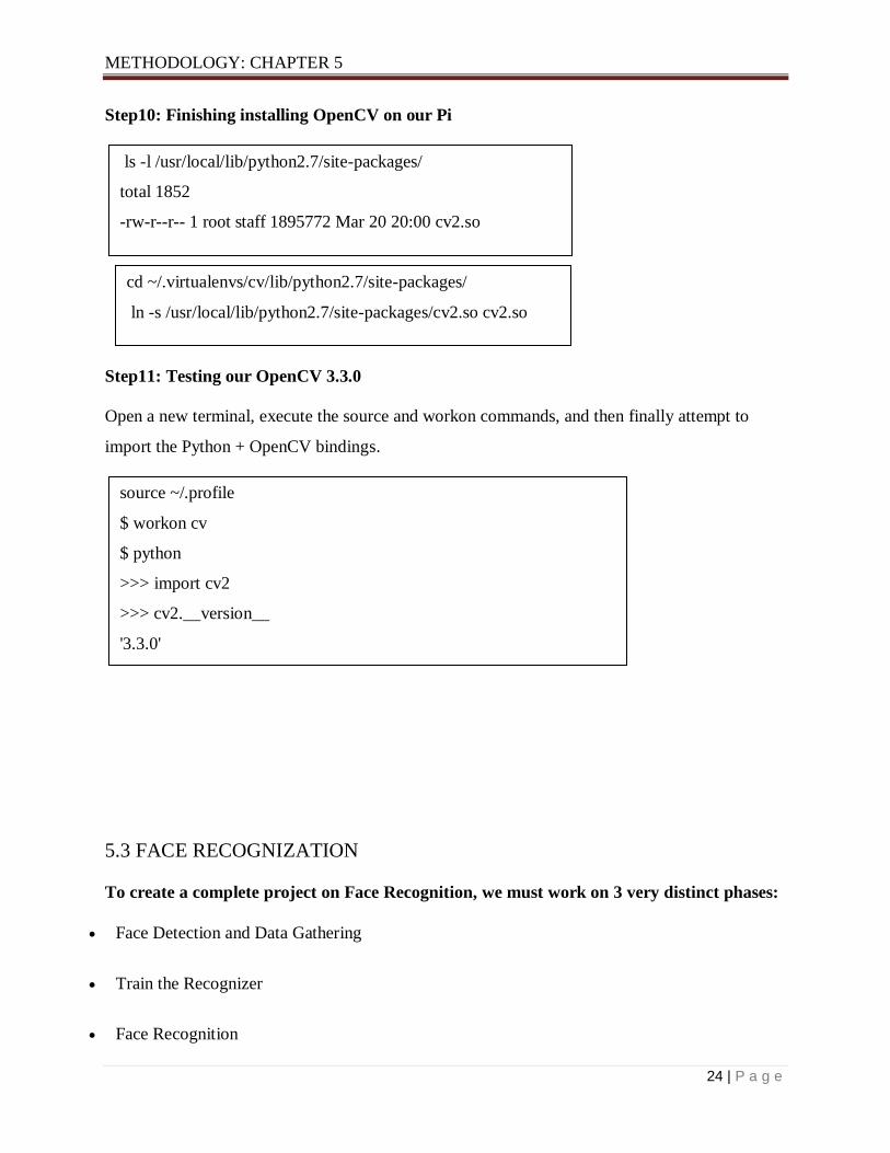
Step10: Finishing installing OpenCV on our Pi
Step11: Testing our OpenCV 3.3.0
Open a new terminal, execute the source and workon commands, and then finally attempt to
import the Python + OpenCV bindings.
5.3 FACE RECOGNIZATION
To create a complete project on Face Recognition, we must work on 3 very distinct phases:
Face Detection and Data Gathering
Train the Recognizer
Face Recognition
ls -l /usr/local/lib/python2.7/site-packages/
total 1852
-rw-r--r-- 1 root staff 1895772 Mar 20 20:00 cv2.so
cd ~/.virtualenvs/cv/lib/python2.7/site-packages/
ln -s /usr/local/lib/python2.7/site-packages/cv2.so cv2.so
source ~/.profile
$ workon cv
$ python
>>> import cv2
>>> cv2.__version__
'3.3.0'
>>>
METHODOLOGY: CHAPTER 5
25 | P a g e
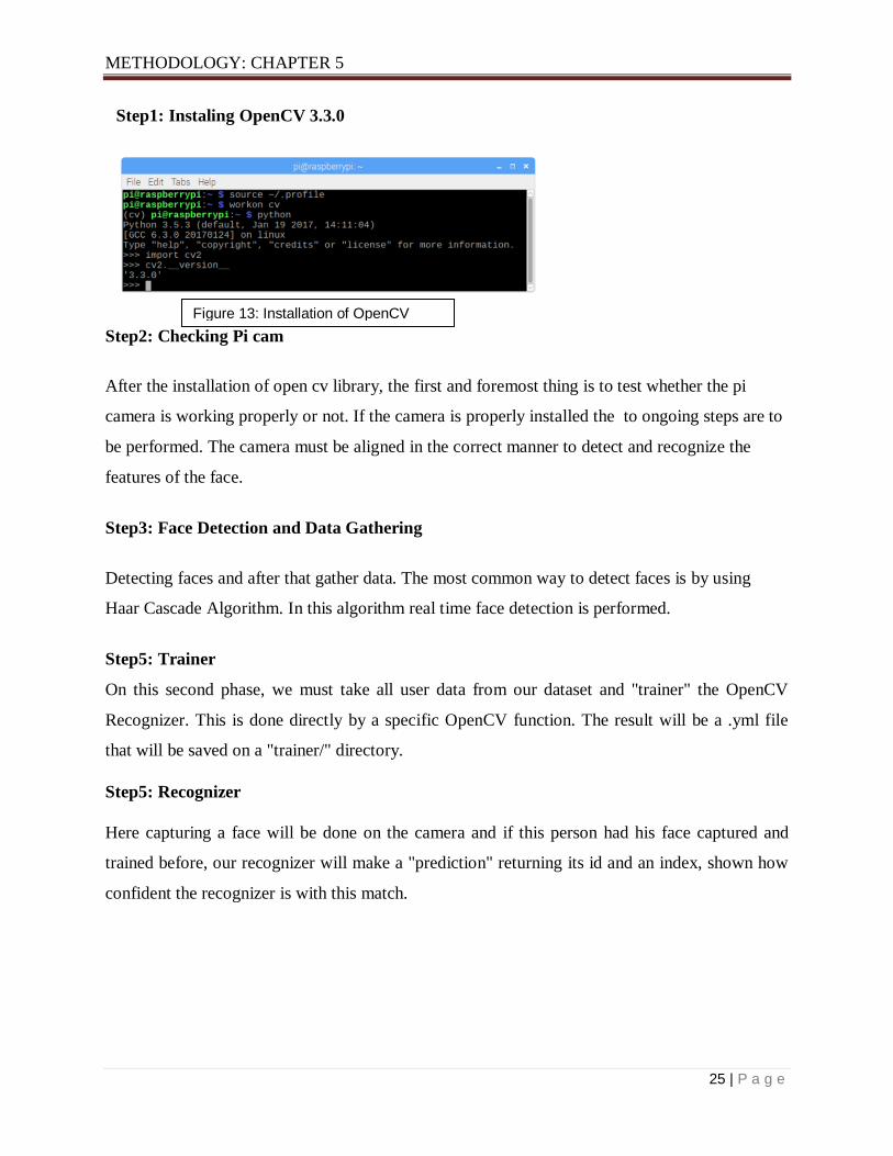
Step1: Instaling OpenCV 3.3.0
Step2: Checking Pi cam
After the installation of open cv library, the first and foremost thing is to test whether the pi
camera is working properly or not. If the camera is properly installed the to ongoing steps are to
be performed. The camera must be aligned in the correct manner to detect and recognize the
features of the face.
Step3: Face Detection and Data Gathering
Detecting faces and after that gather data. The most common way to detect faces is by using
Haar Cascade Algorithm. In this algorithm real time face detection is performed.
Step5: Trainer
On this second phase, we must take all user data from our dataset and "trainer" the OpenCV
Recognizer. This is done directly by a specific OpenCV function. The result will be a .yml file
that will be saved on a "trainer/" directory.
Step5: Recognizer
Here capturing a face will be done on the camera and if this person had his face captured and
trained before, our recognizer will make a "prediction" returning its id and an index, shown how
confident the recognizer is with this match.
Figure 13: Installation of OpenCV

METHODOLOGY: CHAPTER 5
26 | P a g e
Here face recognization has been done using one kind of classifier which is known as Haar
Cascade classifier. In this process of face recognition the most important part is of image
processing. Image processing is a numerically serious task and one of the greatest territories of
research for a major information field. It is a procedure on the picture to change it into desired
looking or which the info is a picture and the output might be a picture or set of characters
related with the specific picture. It alludes to variety of techniques that are utilized to augment
the data output from an image.
5.4 HAAR-CASCADE CLASSIFIER ALGORITHM
It is basically a classifier which is being used to detect objects for which it has been trained for.
First and foremost, the algorithm needs a lot of positive pictures and negative pictures to prepare
the Haar cascade classifier. Positive pictures are pictures with clear faces where negative pictures
are those with no countenances. Each feature is represented as a single value obtained from the
difference of the sums of pixels in white rectangle from the sum of all pixels in the black
rectangle. All different possible sizes and locations of classifier is used for calculating of plenty
of features. As the number of classifiers increase the arithmetic computations seems to take a
long time. Instead of it, the concept of Integral Image has been used. Image Processing Integral
image is a data structure which is a summed area table and algorithm for quickly and efficiently
generating sum of values in a rectangular grid subset. To avoid the complex calculation we use
Adaboost machine learning algorithm, which is inbuilt in OpenCV library that is cascade
classifier, it eliminates the redundancy in the classifiers. Any classifier which has a probability of
50% of more in detection is treated as weak classifier. The Sum of all weak classifier gives a
strong classifier which makes the decision about detection. Classification takes place in stages, if
the selected region fails in the first stage, we discard it. One doesn’t use the classifiers on that
region which is discarded. The region which passes all the stages i.e. all strong classifiers is
treated as the detected face. Detected Faces are passed to the Face recognition phase. Local
Binary Patterns histogram algorithm (LBPH) has been used for face recognition. Local binary
patterns are simple at the same time very efficient texture operator which assigns the pixels of
the image by comparing with the adjacent pixels as threshold and which results in a binary result.
METHODOLOGY: CHAPTER 5
27 | P a g e
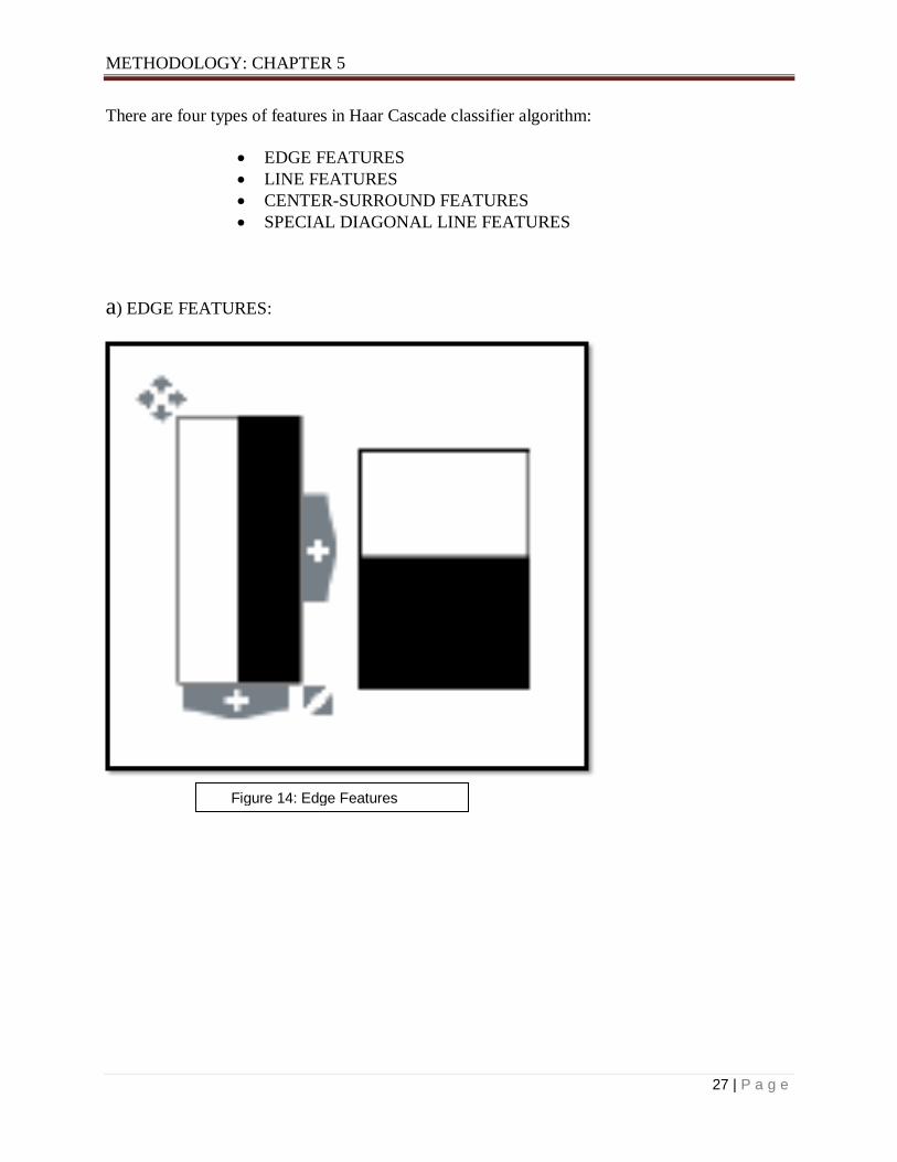
There are four types of features in Haar Cascade classifier algorithm:
EDGE FEATURES
LINE FEATURES
CENTER-SURROUND FEATURES
SPECIAL DIAGONAL LINE FEATURES
a) EDGE FEATURES:
Figure 14: Edge Features

METHODOLOGY: CHAPTER 5
28 | P a g e
b) LINE FEATURES:
c) CENTER-SURROUND FEATURE:
Figure 15: Line Features
Figure 16: Center-surround feature

METHODOLOGY: CHAPTER 5
29 | P a g e
d) SPECIAL DIAGONAL LINE FEATURES:
In this proposed scheme it has been decided to bring on a normal dc motor and connect it with a
relay which will be connected to the main controller Raspberry Pi. The DC Motor will also
connected to any of the pins of Raspberry Pi. DC motor here is helping the miniature door to
open after the face is recognized in Face Recognization process. This whole system is a post part
of the surveillance of Home automation.
Figure 17: Special Diagonal Line Features
RESULTS AND DISCUSSIONS: CHAPTER 6
30 | P a g e
RESULTS AND DISCUSSIONS
The main objective of the proposed work here is to create a system where it will be easy to
operate home appliances and equipments very easily by making this system user friendly.
Developing a smart home system was not easy at first. The most important part of this proposed
work is human surveillance which is important due to the security issues of smart homes. For
surveillance using face detection and face recognization is being used which are the most modern
form of surveillance. For this purpose Raspberry Pi is being used camera and OpenCV which is a
open source which is a part of Python language. Python here acts as the main platform where
most of the work is going to be done. Image processing needs to be done for the Face
recognition. OpenCV is an open source computer vision software library. The library has a lot of
optimized algorithms, which can be used in many IOT related sectors including face detection
and recognition. As the libraries of our project we liked to use the Haar classifier, LBPH (Lower
Binary Pattern histogram) face recognizer. Face recognization is ought to be successful if the
matching index after recognization is more than 45%.
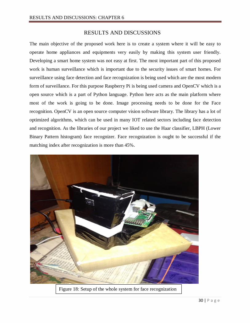
Figure 18: Setup of the whole system for face recognization
RESULTS AND DISCUSSIONS: CHAPTER 6
31 | P a g e
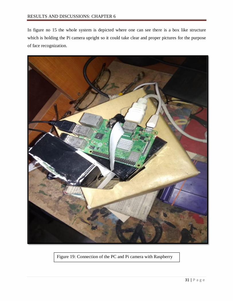
In figure no 15 the whole system is depicted where one can see there is a box like structure
which is holding the Pi camera upright so it could take clear and proper pictures for the purpose
of face recognization.
Figure 19: Connection of the PC and Pi camera with Raspberry
Pi

RESULTS AND DISCUSSIONS: CHAPTER 6
32 | P a g e
In figure 16 and 16(a) it can be seen that how the PC, HDMI and the Pi camera is connected with
the main controller Raspberry Pi. The box like structure is holding the Raspberry Pi camera
which is used for capturing pictures of faces to store in the database and then later detect those
faces and recognize those faces.
Figure 19(a): HDMI cable and Pi camera connection with Raspberry Pi
RESULTS AND DISCUSSIONS: CHAPTER 6
33 | P a g e
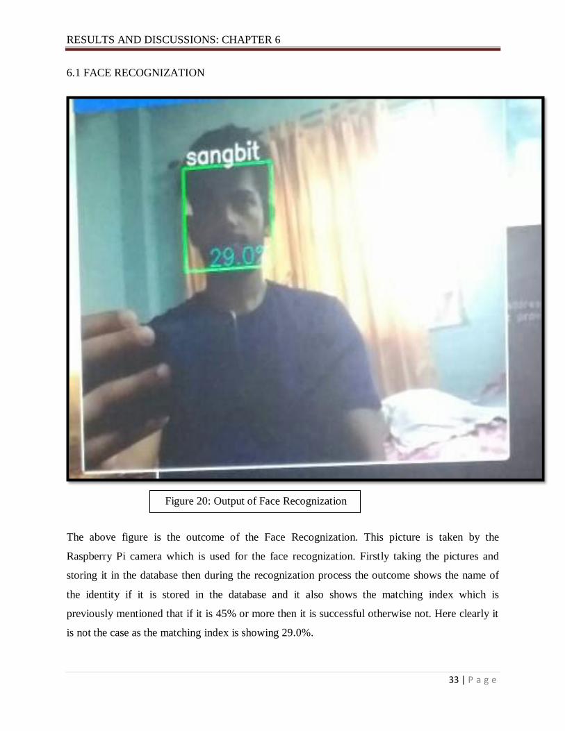
6.1 FACE RECOGNIZATION
The above figure is the outcome of the Face Recognization. This picture is taken by the
Raspberry Pi camera which is used for the face recognization. Firstly taking the pictures and
storing it in the database then during the recognization process the outcome shows the name of
the identity if it is stored in the database and it also shows the matching index which is
previously mentioned that if it is 45% or more then it is successful otherwise not. Here clearly it
is not the case as the matching index is showing 29.0%.
Figure 20: Output of Face Recognization

RESULTS AND DISCUSSIONS: CHAPTER 6
34 | P a g e
In the above figure it is the output of the face recognization and the person is identified properly.
The matching index here is 44% which is almost 45% (the desired matching index) so one can
say here that it is approximately successful.
Figure 20(a): Output of the Face Rcognization

RESULTS AND DISCUSSIONS: CHAPTER 6
35 | P a g e
In the above figure one can see that one face is being recognized as it is stored in the database
and another face is not properly recognized and is showing “Unknown “from here one can
conclude that if the face is not stored in the database previously then the face won’t be
recognized and will show unknown
In this proposed scheme it has been already decided to introduce a smart door lock system where
a miniature door will be used. The door will be driven by a DC motor which will be driven by a
relay. the Pi camera is attached to the camera slot and the DC motor and Relay is attached to
the GPIO pins of the Raspberry Pi. As it is a two channel relay so it is connected to the LED and
the DC motor which helps in driving the DC motor .Here the DC motor drives a miniature door
Figure 20(b): Outcome of the face recognization process

RESULTS AND DISCUSSIONS: CHAPTER 6
36 | P a g e
which is being used for a door locking system for surveillance purposes. The door only opens
after a successful recognization process, when the face is stored previously in the database and
that image has got the access to open the door then it will work otherwise it won’t open.

CONCLUSION AND FUTRURE WORKS: CHAPTER 7
37 | P a g e
CONCLUSION AND FUTURE WORKS
Home Automation is the most trending technology currently. This form of technology includes a
lot of prospects from a lot of topics or subject assembled together. Home automation here has
almost brought a evolutionary change in handling or operating home appliances and equipments
and made it easy and convenient to use home appliances. A lot of home appliances can be
controlled through home automation such as lights, fans, TV, air conditioners, fridge etc. Home
automation helps us in operating this appliances from far away. In this proposed scheme an effort
has been made to build a home automation system with the main virtue of Face Recognization.
Face Recognization here has been done with the help of a Raspberry Pi camera which was used
to take pictures of the faces and store it in the database where. The whole recognizarion has been
done on Open CV which is a library function in Python language and is an open source. OpenCV
is an open source computer vision software library. The library has a lot of optimized algorithms,
which can be used in many IOT related sectors including face detection and recognition. As the
libraries of our project we liked to use the Haar classifier, LBPH (Lower Binary Pattern
histogram) face recognizer. Face recognization is ought to be successful if the matching index
after recognization is more than 45%. In figure20 we are seeing the output of the Face
Recognization. Firstly taking the pictures and storing it in the database then during the
recognization process the outcome shows the name of the identity if it is stored in the database
and it also shows the matching index which is previously mentioned that if it is 45% or more
then it is successful otherwise not. Here clearly it is not the case as the matching index is
showing 29.0%. In figure 20(a) one can see that the output of the face recognization and the
person is identified properly. The matching index here is 44% which is almost 45% (the desired
matching index) so we can say here that it is approximately successful. And in another picture
one other face has been added where the image of the face was not stored previously so as a
result it is showing unknown. In this proposed scheme a door lock system is also going to be
used which will help in making the security part more strong. The door will be driven by a DC
motor which will be connected to a relay. To better the Face recognition performance, there are
miscellaneous things that can be improved here, some of them being fairly easy to go with. For
example, you could add color processing, edge detection, etc. Today, one of the fields that
utilizes facial recognition the most is security. Facial recognition is an extremely viable
apparatus that can help law masters perceive offenders and programming organizations are

CONCLUSION AND FUTRURE WORKS: CHAPTER 7
38 | P a g e
utilizing the innovation to enable clients to get to their innovation. This innovation can be
additionally created to be utilized in different roads, for example, ATMs, getting to secret
documents, or other touchy materials. This can make other safety efforts, for example, passwords
and keys old. Another way that trend-setters are hoping to execute facial acknowledgment is
inside trams and other transportation outlets. They are hoping to use this innovation to utilize
faces as charge cards to pay for your transportation expense. Rather than setting off to a stall to
purchase a ticket for an admission, the face acknowledgment would take your face, run it
through a framework, and charge the record that you've recently made. This could conceivably
streamline the procedure and advance the stream of traffic definitely.

REFERENCES: CHAPTER 8
39 | P a g e
[1] Electronics Industries Association, Consumer Electronics Group, EIA Home Automation
System: EIA/Is-60, EIA ,1992.
[2] D.L. Cross, C. Douligeris; “A Fiber Optic Home Automation System”, IEEE Transactions on
Consumer Electronics, Vol. 39, No. 3, August 1993,pp. 636-645.
[3] C. Douligiris; “Intelligent Home Systems” IEEE Communication Magazine, October 1993,
pp. 52-61
[4] W.Y. Chen; “Emerging Home Digital Networking Needs”, Proc. 4th IEEE Int. workshop on
Community Networking, Atlanta, 1997, pp. 7-12..
[5] H. Fujieda, Y. Horiike, T. Yamamoto and T. Nomura; “A Wireless Home Network and its
Application Systems”, IEEE Transactions on Consumer Electronics, Vol. 46, No. 2, May 2000,
pp. 283-290.
[6] H.Oh, H.Bahn, K.J. Chae; “An Energy-Efficient Sensor Routing Scheme for Home
Automation Networks”, IEEE Transactions on Consumer Electronics, Vol. 51, No.3, August
2005.
[7] Mario Kolberg & Evan H. Magill; “Using Pen and Paper to control Networked Appliances”,
IEEE Communications Magazine, November 2006, pp. 148-154.
[8] Al-Ali A. R and Al-Rousan M., "Java-based home automation system", IEEE Transactions
on Consumer Electronics, vol. 50, 2003,no. 2, pp. 498-504.
[9] N.Kushiro., S.Suzuki., M.Nakata., H.Takahara and M.Inoue,” Integrated Residential
Gateway Controller For Home Automation System” IEEE Transactions On Consumer
Electronics, vol. 59, No. 3 August 2003.
[10] I.Cogkun and H.A.G.Universitesi, T.E.Fakultesi, E.E.Bolumu., “A Remote Controller For
Home And Office Appliances By Telephone”, IEEE Transactions on Consumer Electronics, Vol.
44, No. 4, November 1998.
[11] Narendra M and Vijaylakshmi M,"Raspberry pi based advanced scheduled home
automation system through E-mail", Chennai, 2014.

REFERENCES: CHAPTER 8
40 | P a g e
[12] R.A.Ramlee, D.H.Z.Tang dan M.M.Ismail(2012), “Smart Home System For Disabled
People Via Wireless Bluetooth”, IEEE International Conference on System Engineering and
Technology ,pp. 978-983,2012.
[13] G.Birajda and S.Mahindrakar, “Embedded web server based home automation using
raspberry pi”, International Journal of Modern Trends in Engineering and Research, vol. 1, no.5
,,India,September2014.
[14] H Bharathi ,U Srivani, MD Azharudhin, M Srikanth and M Sukumarline, "Home
Automation by Using Raspberry Pi And Android Application", Department of Electronics and
Communication Engineering, MLR Institute of Technology, Hyderabad,India,2017.
[15] Paul Viola and Michael Jones, “Rapid object detection using boosted cascade of simple
Features”, IEEE Conference on Computer vision and Pattern Recognition, 2001, Vol.1,pp. 511-
518.
[16] C. Papageorgiou, M. Oren and T. Poggio, “A general framework for object detection”,
InInternational Conference on Computer Wsion, Bombay, Jan 1998, pp. 555-562.
[17] N.V. Naik, A.Venunadan and Kumara .K .R,"Face Detection on Open CV using Raspberry
Pi", Department of ECE,GSIT, Karwar, Karnataka, IJEECS, volume6, 2017.
[18] T.Patel and B.Shah, “A Survey on Facial Feature Extraction Techniques for Automatic Face
Annotation”, IEEE International Conference on Innovative Mechanisms for Industry
Applications (ICIMIA),Bangalore, India, 2017.
[19] J.J. Patoliya and M.M. Desai, “Face Detection based ATM Security System using
Embedded Linux Platform”, IEEE 2017 2nd International Conference for Convergence in
Technology (I2CT),Mumbai, India,2017.
[20] M.Heshmat, W.M. Abd-Elhafiez, M.Girgisand S.Elaw, “Face Identification System in
Video”, IEEE 2016 11th International Conference on Computer Engineering & Systems
(ICCES), Cairo, Egypt,2016.
REFERENCES: CHAPTER 8
41 | P a g e
[21] J.C Yang, "An Intelligent Automated Door Control System Based on a Smart
Camera".2012.
[22] W. F. Abaya, J. Basa, M. Sy, A. C. Abad and E.P. Dadios, "Low cost smart security camera
with night vision capability using Raspberry Pi and OpenCV," 2014 International Conference on
Humanoid, Nanotechnology, Information Technology, Communication and Control,
Environment and Management (HNICEM), Palawan, 2014, pp. 1-6
[23] P.Pasumarti1, P. P. Sekhar “Classroom Attendance Using Face Detection and Raspberry-Pi”
International Research journal of Engineering and Technology (IRJET), Volume: 05 Issue: 03.
p3-p5,Mar-2018
[24] S.Rajkumar, J.Prakash, “Automated attendance using Raspberry pi”, International Journal
Of Pharmacy & Technology (IJPT), Vol. 8, No. 3, pp. 16214-16221, September 2016.-
[25] T. M. Inc., “Train a Cascade Object Detector,”[Online]. Available:
http://www.mathworks.se/help/vision/ug/traina-cascadeobject-d
[26] S.Roy, Md.N.Uddin, Md.Z.Haque,Md.J Kabir,"Design and Implementation of the Smart
Door Lock System with Face Recognition Method using the Linux Platform Raspberry
Pi",IJCSN - International Journal of Computer Science and Network, Volume 7, Issue 6,
December 2018.
[27] N.Saini, S.Kaur and H.Singh A Review: Face Detection Methods And Algorithms,
International Journal of Engineering Research & Technology (IJERT) ISSN:2278-0181
www.ijert.org Vol. 2 Issue 6, June – 2013.
DATASHEETS
42 | P a g e
1 Introduction
The Raspberry Pi Compute Module 3+ (CM3+) is a range of DDR2-SODIMM-mechanically-
compatible System on Modules (SoMs) containing processor, memory, eMMC Flash (on
non-Lite variants) and supporting power circuitry. These modules allow a designer to
leverage the Raspberry Pi hardware and software stack in their own custom systems and
form factors. In addition these modules have extra IO interfaces over and above what is
available on the Raspberry Pi model A/B boards, opening up more options for the designer.
The CM3+ contains a BCM2837B0 processor (as used on the Raspberry Pi 3B+), 1Gbyte
LPDDR2 RAM and eMMC Flash. The CM3+ is currently available in 4 variants, CM3+/8GB,
CM3+/16GB, CM3+/32GB and CM3+ Lite, which have 8, 16 and 32 Gigabytes of eMMC
Flash, or no eMMC Flash, respectively.
The CM3+ Lite product is the same as CM3+ except the eMMC Flash is not fitted, and the
SD/eMMC interface pins are available for the user to connect their own SD/eMMC device.
Note that the CM3+ is electrically identical and, with the exception of higher CPU z-height,
physically identical to the legacy CM3 products. CM3+ modules require a software/firmware image dated November 2018 or newer to function correctly.

DATASHEETS
43 | P a g e
2 Features
2.1 Hardware
Low cost
Low power
High availability
High reliability
– Tested over millions of Raspberry Pis Produced to date
– Module IO pins have 15 micro-inch hard gold plating over 2.5 micron Nickel
2.2 Peripherals
48x GPIO
2x I2C
2x SPI
2x UART
2x SD/SDIO
1x HDMI 1.3a
1x USB2 HOST/OTG
1x DPI (Parallel RGB Display)
1x NAND interface (SMI)
1x 4-lane CSI Camera Interface (up to 1Gbps per lane)
1x 2-lane CSI Camera Interface (up to 1Gbps per lane)
1x 4-lane DSI Display Interface (up to 1Gbps per lane)
1x 2-lane DSI Display Interface (up to 1Gbps per lane)
2.3 Software
ARMv8 Instruction Set
Mature and stable Linux software stack
– Latest Linux Kernel support
– Many drivers upstreamed
– Stable and well supported userland
– Full availability of GPU functions using standard APIs

DATASHEETS
44 | P a g e
3 Block Diagram
20
0 P
in S
OD
IMM
Co
nn
ecto
r
EMMC_EN_N_1V8
IO Expander
HDMI_HPD_N_1V8
VBAT
Core SMPS
3V3
1V8
VDAC
TV
TVDAC
DAC
VDD_GPIO0-27
BCM2837B0
GPIO
GPIO[0:27]
BANK0
VDD_GPIO28-45
GPIO
GPIO[28:45]
BANK1 1GByte LPDDR2
CSI CAM0
2 Lane CSI Camera
CSI CAM1
4 Lane CSI Camera
DSI DISP0
2 Lane DSI Display
DSI DISP1
4 Lane DSI Display
HDMI TMDS
CM
CHOKES CLOCK & DATA 4GByte eMMC
HDMI CEC, DDC
(CM3 only)
HDMI CEC & I2C
USB
USB2
USB_OTGID SD I/O VOLTAGE
1V8
CM3+ eMMC I/O
JTAG
SD_CMD, Dx
Voltage fixed at
3V3
RUN
SD_CLK
1V8
RUN
CM3+ Lite
3V3
SD I/O Voltage
EMMC_DISABLE_N
supplied from
SDX_VDD
SDX_CLK (CM3+ Lite only)
SDX_CMD, Dx (CM3+ Lite only)
SDX_VDD (CM3+ Lite only)
Figure 1: CM3+ Block Diagram

DATASHEETS
45 | P a g e
4 Mechanical Specification
The CM3+ modules conform to JEDEC MO-224 mechanical specification for 200 pin DDR2
(1.8V) SODIMM modules and therefore should work with the many DDR2 SODIMM sockets
available on the market. (Please note that the pinout of the Compute Module is not the same
as a DDR2 SODIMM module; they are not electrically compatible.) The SODIMM form factor was chosen as a way to provide the 200 pin connections using a
standard, readily available and low cost connector compatible with low cost PCB manufacture. The maximum component height on the underside of the Compute Module is 1.2mm.
The maximum component height on the top side of the Compute Module is 2.5mm.
The Compute Module PCB thickness is 1.0mm +/- 0.1mm.
Note that the location and arrangement of components on the Compute Module may change
slightly over time due to revisions for cost and manufacturing considerations; however,
maximum component heights and PCB thickness will be kept as specified. Figure 2 gives the CM3+ mechanical dimensions.
Figure 2: CM3+ Mechanical Dimensions

DATASHEETS
46 | P a g e
5 Pin Assignments
CM3+ CM3+ Lite PIN PIN CM3+ CM3+ Lite
GND 1 2 EMMC_DISABL E_N GPIO0 3 4 NC SDX_VDD GPIO1 5 6 NC SDX_VDD GND 7 8 GND GPIO2 9 10 NC SDX_CLK GPIO3 11 12 NC SDX_ C MD GND 13 14 GND GPIO4 15 16 NC SDX_D0 GPIO5 17 18 NC SDX_D1 GND 19 20 GND GPIO6 21 22 NC SDX_D2 GPIO7 23 24 NC SDX_D3 GND 25 26 GND GPIO8 27 28 GPIO28 GPIO9 29 30 GPIO29 GND 31 32 GND GPIO10 33 34 GPIO30 GPIO11 35 36 GPIO31 GND 37 38 GND
GPIO0-27_VDD 39 40 GPIO0-27_VDD KEY
GPIO28-45_VDD 41 42 GPIO28-45_VDD GND 43 44 GND GPIO12 45 46 GPIO32 GPIO13 47 48 GPIO33 GND 49 50 GND GPIO14 51 52 GPIO34 GPIO15 53 54 GPIO35 GND 55 56 GND GPIO16 57 58 GPIO36 GPIO17 59 60 GPIO37 GND 61 62 GND GPIO18 63 64 GPIO38 GPIO19 65 66 GPIO39 GND 67 68 GND GPIO20 69 70 GPIO40 GPIO21 71 72 GPIO41 GND 73 74 GND GPIO22 75 76 GPIO42 GPIO23 77 78 GPIO43 GND 79 80 GND GPIO24 81 82 GPIO44 GPIO25 83 84 GPIO45 GND 85 86 GND GPIO26 87 88 HDMI_HPD_N_1V8 GPIO27 89 90 EMMC_EN_N_1V8 GND 91 92 GND
DSI0_DN1 93 94 DSI1_DP0 DSI0_DP1 95 96 DSI1_DN0
GND 97 98 GND DSI0_DN0 99 100 DSI1_CP DSI0_DP0 101 102 DSI1_CN
GND 103 104 GND DSI0_CN 105 106 DSI1_DP3 DSI0_CP 107 108 DSI1_DN3 GND 109 110 GND
HDMI_CLK_N 111 112 DSI1_DP2 HDMI_CLK_P 113 114 DSI1_DN2
GND 115 116 GND HDMI_D0_N 117 118 DSI1_DP1 HDMI_D0_P 119 120 DSI1_DN1
GND 121 122 GND HDMI_D1_N 123 124 NC HDMI_D1_P 125 126 NC
GND 127 128 NC HDMI_D2_N 129 130 NC HDMI_D2_P 131 132 NC
GND 133 134 GND CAM1_DP3 135 136 CAM0_DP0 CAM1_DN3 137 138 CAM0_DN0
GND 139 140 GND CAM1_DP2 141 142 CAM0_CP CAM1_DN2 143 144 CA M0_ CN
GND 145 146 GND CAM1_CP 147 148 CAM0_DP1 CAM1_CN 149 150 CAM0_DN1
GND 151 152 GND CAM1_DP1 153 154 NC CAM1_DN1 155 156 NC
GND 157 158 NC CAM1_DP0 159 160 NC CAM1_DN0 161 162 NC
GND 163 164 GND USB_ DP 165 166 TVDAC USB_DM 167 168 USB_OTGID GND 169 170 GND
HD MI_CEC 171 172 VC_TRST_N HD MI_SD A 173 174 VC_TDI HD MI_ SCL 175 176 VC_T MS
RUN 177 178 VC_TDO DD_COR E (DO NOT CON NECT 179 180 VC_TCK
GND 181 182 GND 1V8 183 184 1V8 1V8 185 186 1V8 GND 187 188 GND VDAC 189 190 VDAC 3V3 191 192 3V3 3V3 193 194 3V3 GND 195 196 GND VBAT 197 198 VBAT VBAT 199 200 VBAT
Table 2: Compute Module 3+ SODIMM Connector Pinout
Table 2 gives the Compute Module 3+ pinout and Table 3 gives the pin functions.

DATASHEETS
47 | P a g e
Pin Name DIR Voltage Ref PDNa State If Unused Description/Notes
RUN and Boot Control (see text for usage guide)
RUN I 3V3b Pull High Leave open Has internal 10k pull up
EMMC DISABLE N I 3V3b Pull High Leave open Has internal 10k pull up
EMMC EN N 1V8 O 1V8 Pull High Leave open Has internal 2k2 pull up
GPIO
GPIO[27:0] I/O GPIO0-27 VDD Pull or Hi-Zc Leave open GPIO Bank 0
GPIO[45:28] I/O GPIO28-45 VDD Pull or Hi-Zc Leave open GPIO Bank 1
Primary SD Interfaced;e
SDX CLK O SDX VDD Pull High Leave open Primary SD interface CLK SDX CMD I/O SDX VDD Pull High Leave open Primary SD interface CMD SDX Dx I/O SDX VDD Pull High Leave open Primary SD interface DATA
USB Interface
USB Dx I/O - Z Leave open Serial interface USB OTGID I 3V3 Tie to GND OTG pin detect
HDMI Interface
HDMI SCL I/O 3V3b Z
f Leave open DDC Clock (5.5V tolerant) HDMI SDA I/O 3V3
b Zf Leave open DDC Data (5.5V tolerant)
HDMI CEC I/O 3V3 Z Leave open CEC (has internal 27k pull up) HDMI CLKx O - Z Leave open HDMI serial clock HDMI Dx O - Z Leave open HDMI serial data HDMI HPD N 1V8 I 1V8 Pull High Leave open HDMI hotplug detect
CAM0 (CSI0) 2-lane Interface
CAM0 Cx I - Z Leave open Serial clock CAM0 Dx I - Z Leave open Serial data
CAM1 (CSI1) 4-lane Interface
CAM1 Cx I - Z Leave open Serial clock CAM1 Dx I - Z Leave open Serial data
DSI0 (Display 0) 2-lane Interface
DSI0 Cx O - Z Leave open Serial clock DSI0 Dx O - Z Leave open Serial data
DSI1 (Display 1) 4-lane Interface
DSI1 Cx O - Z Leave open Serial clock DSI1 Dx O - Z Leave open Serial data
TV Out
TVDAC O - Z Leave open Composite video DAC output
JTAG Interface
TMS I 3V3 Z Leave open Has internal 50k pull up TRST N I 3V3 Z Leave open Has internal 50k pull up TCK I 3V3 Z Leave open Has internal 50k pull up TDI I 3V3 Z Leave open Has internal 50k pull up TDO O 3V3 O Leave open Has internal 50k pull up a The PDN column indicates power-down state (when RUN pin
LOW) b Must be driven by an open-collector driver
c GPIO have software enabled pulls which keep state over
power-down d Only available on Lite variants
e The CM will always try to boot from this interface first
f Requires external pull-up resistor to 5V as per HDMI spec
Table 3: Pin Functions

DATASHEETS
48 | P a g e
6 Electrical Specification
Caution! Stresses above those listed in Table 4 may cause permanent damage to the device.
This is a stress rating only; functional operation of the device under these or any other conditions
above those listed in the operational sections of this specification is not implied. Exposure to
absolute maximum rating conditions for extended periods may affect device reliability.
Symbol Parameter Minimum Maximum Unit
VBAT Core SMPS Supply -0.5 6.0 V
3V3 3V3 Supply Voltage -0.5 4.10 V
1V8 1V8 Supply Voltage -0.5 2.10 V
VDAC TV DAC Supply -0.5 4.10 V
GPIO0-27 VDD GPIO0-27 I/O Supply Voltage -0.5 4.10 V
GPIO28-45 VDD GPIO28-45 I/O Supply Voltage -0.5 4.10 V
SDX VDD Primary SD/eMMC Supply Voltage -0.5 4.10 V
Table 4: Absolute Maximum Ratings
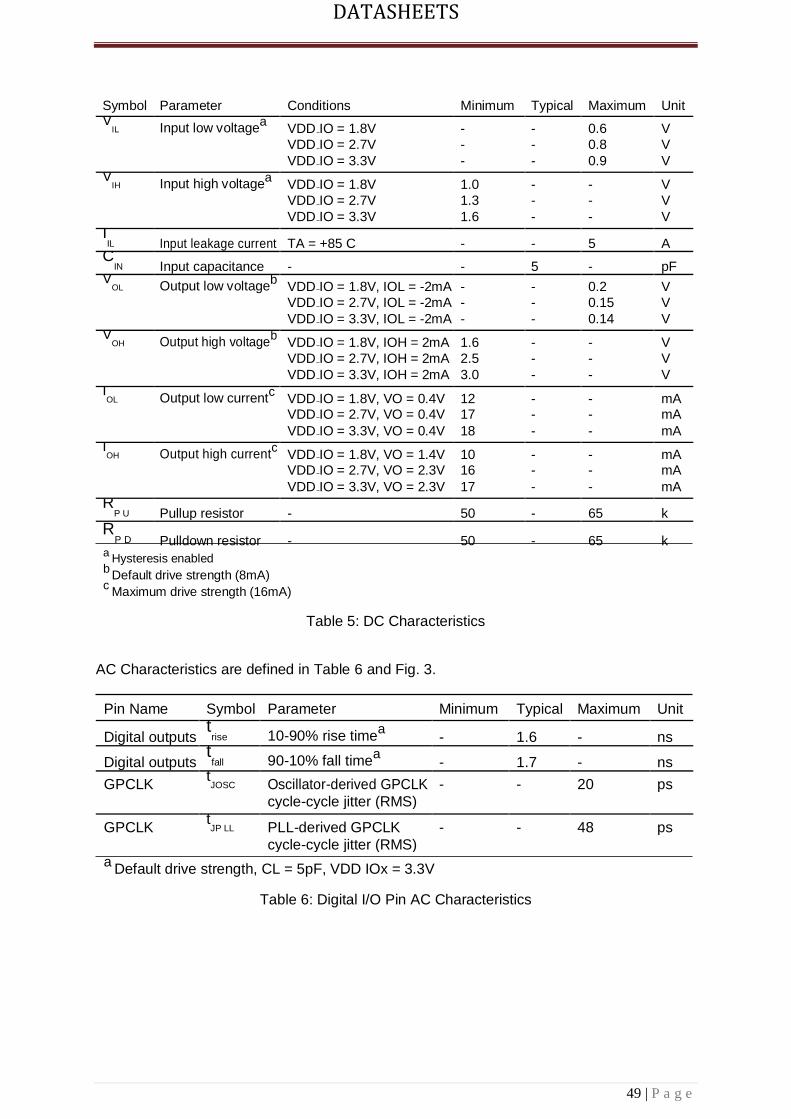
DC Characteristics are defined in Table 5
DATASHEETS
49 | P a g e
Symbol Parameter Conditions Minimum Typical Maximum Unit
VIL Input low voltage
a VDD IO = 1.8V - - 0.6 V
VDD IO = 2.7V - - 0.8 V
VDD IO = 3.3V - - 0.9 V
VIH Input high voltage
a VDD IO = 1.8V 1.0 - - V
VDD IO = 2.7V 1.3 - - V
VDD IO = 3.3V 1.6 - - V
IIL Input leakage current TA = +85 C - - 5 A
CIN Input capacitance - - 5 - pF
VOL Output low voltage
b VDD IO = 1.8V, IOL = -2mA - - 0.2 V
VDD IO = 2.7V, IOL = -2mA - - 0.15 V
VDD IO = 3.3V, IOL = -2mA - - 0.14 V
VOH Output high voltage
b VDD IO = 1.8V, IOH = 2mA 1.6 - - V
VDD IO = 2.7V, IOH = 2mA 2.5 - - V
VDD IO = 3.3V, IOH = 2mA 3.0 - - V
IOL Output low current
c VDD IO = 1.8V, VO = 0.4V 12 - - mA
VDD IO = 2.7V, VO = 0.4V 17 - - mA
VDD IO = 3.3V, VO = 0.4V 18 - - mA
IOH Output high current
c VDD IO = 1.8V, VO = 1.4V 10 - - mA
VDD IO = 2.7V, VO = 2.3V 16 - - mA
VDD IO = 3.3V, VO = 2.3V 17 - - mA
RP U Pullup resistor - 50 - 65 k
RP D Pulldown resistor - 50 - 65 k
a Hysteresis enabled
b Default drive strength (8mA)
c Maximum drive strength (16mA)
Table 5: DC Characteristics
AC Characteristics are defined in Table 6 and Fig. 3.
Pin Name Symbol Parameter Minimum Typical Maximum Unit
Digital outputs trise 10-90% rise time
a - 1.6 - ns
Digital outputs tfall 90-10% fall time
a - 1.7 - ns
GPCLK tJOSC Oscillator-derived GPCLK - - 20 ps
cycle-cycle jitter (RMS)
GPCLK tJP LL PLL-derived GPCLK - - 48 ps
cycle-cycle jitter (RMS) a Default drive strength, CL = 5pF, VDD IOx = 3.3V
Table 6: Digital I/O Pin AC Characteristics

DATASHEETS
50 | P a g e
tfall trise
DIGITAL
OUTPUT
Figure 3: Digital IO Characteristics
7 Power Supplies
The Compute Module 3+ has six separate supplies that must be present and powered at all
times; you cannot leave any of them unpowered, even if a specific interface or GPIO bank is
unused. The six supplies are as follows:
1. VBAT is used to power the BCM2837 processor core. It feeds the SMPS that
generates the chip core voltage.
2. 3V3 powers various BCM2837 PHYs, IO and the eMMC Flash.
3. 1V8 powers various BCM2837 PHYs, IO and SDRAM.
4. VDAC powers the composite (TV-out) DAC.
5. GPIO0-27 VREF powers the GPIO 0-27 IO bank.
6. GPIO28-45 VREF powers the GPIO 28-45 IO bank.
Supply Descripion Minimum Typical Maximum Unit
VBAT Core SMPS Supply 2.5 - 5.0 + 5% V
3V3 3V3 Supply Voltage 3.3 - 5% 3.3 3.3 + 5% V
1V8 1V8 Supply Voltage 1.8 - 5% 1.8 1.8 + 5% V
VDAC TV DAC Supplya
2.5 - 5% 2.8 3.3 + 5% V
GPIO0-27 VDD GPIO0-27 I/O Supply Voltage 1.8 - 5% - 3.3 + 5% V
GPIO28-45 VDD GPIO28-45 I/O Supply Voltage 1.8 - 5% - 3.3 + 5% V
SDX VDD Primary SD/eMMC Supply Voltage 1.8 - 5% - 3.3 + 5% V
a Requires a clean 2.5-2.8V supply if TV DAC is used, else connect to 3V3
Table 7: Power Supply Operating Ranges

DATASHEETS
51 | P a g e
7.1 Supply Sequencing
Supplies should be staggered so that the highest voltage comes up first, then the remaining voltages
in descending order. This is to avoid forward biasing internal (on-chip) diodes between supplies, and
causing latch-up. Alternatively supplies can be synchronised to come up at exactly the same time as
long as at no point a lower voltage supply rail voltage exceeds a higher voltage supply rail voltage.
7.2 Power Requirements
Exact power requirements will be heavily dependent upon the individual use case. If an on-
chip subsys-tem is unused, it is usually in a low power state or completely turned off. For
instance, if your application does not use 3D graphics then a large part of the core digital
logic will never turn on and need power. This is also the case for camera and display
interfaces, HDMI, USB interfaces, video encoders and decoders, and so on.
Powerchain design is critical for stable and reliable operation of the Compute Module 3+. We
strongly recommend that designers spend time measuring and verifying power requirements
for their particular use case and application, as well as paying careful attention to power
supply sequencing and maximum supply voltage tolerance.
Table 8 specifies the recommended minimum power supply outputs required to power the
Compute Module 3+.
Supply Minimum Requirement Unit
VBAT (CM1) 2000a
mW
VBAT (CM3,3L) 3500a
mW
3V3 250 mA
1V8 250 mA
VDAC 25 mA
GPIO0-27 VDD 50b mA
GPIO28-45 VDD 50b mA
SDX VDD 50
b mA
a Recommended minimum. Actual power drawn is very dependent on use-case
b Each GPIO can supply up to 16mA, aggregate current per bank must not exceed
50mA Table 8: Mimimum Power Supply Requirements
8 Booting
The eMMC Flash device on CM3+ is directly connected to the primary BCM2837 SD/eMMC
interface. These connections are not accessible on the module pins. On CM3+ Lite this SD
interface is available on the SDX pins.

DATASHEETS
52 | P a g e
When initially powered on, or after the RUN pin has been held low and then released, the BCM2837
will try to access the primary SD/eMMC interface. It will then look for a file called bootcode.bin on the
primary partition (which must be FAT) to start booting the system. If it cannot access the SD/eMMC
device or the boot code cannot be found, it will fall back to waiting for boot code to be written to it over
USB; in other words, its USB port is in slave mode waiting to accept boot code from a suitable host. A USB boot tool is available on Github which allows a host PC running Linux to write the
BCM2837 boot code over USB to the module. That boot code then runs and provides access to
the SD/eMMC as a USB mass storage device, which can then be read and written using the host
PC. Note that a Raspberry Pi can be used as the host machine. For those using Windows a
precompiled and packeged tool is available. For more information see here. The Compute Module has a pin called EMMC DISABLE N which when shorted to GND will disable
the SD/eMMC interface (by physically disconnecting the SD CMD pin), forcing BCM2837 to boot from
USB. Note that when the eMMC is disabled in this way, it takes a couple of seconds from powering up
for the processor to stop attempting to talk to the SD/eMMC device and fall back to booting from USB. Note that once booted over USB, BCM2837 needs to re-enable the SD/eMMC device (by releasing
EMMC DISABLE N) to allow access to it as mass storage. It expects to be able to do this by driving
the EMMC EN N 1V8 pin LOW, which at boot is initially an input with a pull up to 1V8. If an end user
wishes to add the ability to access the SD/eMMC over USB in their product, similar circuitry to that
used on the Compute Module IO Board to enable/disable the USB boot and SD/eMMC must be used;
that is, EMMC DISABLE N pulled low via MOSFET(s) and released again by MOSFET, with the gate
controlled by EMMC EN N 1V8. Ensure you use MOSFETs suitable for switching at 1.8V (i.e. use a
device with gate threshold voltage, Vt, suitable for 1.8V switching).
9 Peripherals
9.1 GPIO
BCM2837 has in total 54 GPIO lines in 3 separate voltage banks. All GPIO pins have at least two
alternative functions within the SoC. When not used for the alternate peripheral function, each GPIO
pin may be set as an input (optionally as an interrupt) or an output. The alternate functions are usually
peripheral I/Os, and most peripherals appear twice to allow flexibility on the choice of I/O voltage. GPIO bank2 is used on the module to connect to the eMMC device and for an on-board I2C bus
(to talk to the core SMPS and control the special function pins). On CM3+ Lite most of bank2 is
exposed to allow a user to connect their choice of SD card or eMMC device (if required). Bank0 and 1 GPIOs are available for general use. GPIO0 to GPIO27 are bank0 and
GPIO28-45 make up bank1. GPIO0-27 VDD is the power supply for bank0 and GPIO28-45
VDD is the power supply for bank1. SDX VDD is the supply for bank2 on CM3+ Lite. These
supplies can be in the range 1.8V-3.3V (see Table 7) and are not optional; each bank must
be powered, even when none of the GPIOs for that bank are used. Note that the HDMI HPD N 1V8 and EMMC EN N 1V8 pins are 1.8V IO and are used for
special functions (HDMI hot plug detect and boot control respectively). Please do not use
these pins for any other purpose, as the software for the module will always expect these
pins to have these special functions. If they are unused please leave them unconnected.

DATASHEETS
53 | P a g e
All GPIOs except GPIO28, 29, 44 and 45 have weak in-pad pull-ups or pull-downs enabled
when the device is powered on. It is recommended to add off-chip pulls to GPIO28, 29, 44
and 45 to make sure they never float during power on and initial boot.
9.1.1 GPIO Alternate Functions
Default
GPIO Pull ALT0 ALT1 ALT2 ALT3 ALT4 ALT5
0 High SDA0 SA5 PCLK - - -
1 High SCL0 SA4 DE - - -
2 High SDA1 SA3 LCD VSYNC - - -
3 High SCL1 SA2 LCD HSYNC - - -
4 High GPCLK0 SA1 DPI D0 - - ARM TDI
5 High GPCLK1 SA0 DPI D1 - - ARM TDO
6 High GPCLK2 SOE N DPI D2 - - ARM RTCK
7 High SPI0 CE1 N SWE N DPI D3 - - -
8 High SPI0 CE0 N SD0 DPI D4 - - -
9 Low SPI0 MISO SD1 DPI D5 - - -
10 Low SPI0 MOSI SD2 DPI D6 - - -
11 Low SPI0 SCLK SD3 DPI D7 - - -
12 Low PWM0 SD4 DPI D8 - - ARM TMS
13 Low PWM1 SD5 DPI D9 - - ARM TCK
14 Low TXD0 SD6 DPI D10 - - TXD1
15 Low RXD0 SD7 DPI D11 - - RXD1
16 Low FL0 SD8 DPI D12 CTS0 SPI1 CE2 N CTS1
17 Low FL1 SD9 DPI D13 RTS0 SPI1 CE1 N RTS1
18 Low PCM CLK SD10 DPI D14 - SPI1 CE0 N PWM0
19 Low PCM FS SD11 DPI D15 - SPI1 MISO PWM1
20 Low PCM DIN SD12 DPI D16 - SPI1 MOSI GPCLK0
21 Low PCM DOUT SD13 DPI D17 - SPI1 SCLK GPCLK1
22 Low SD0 CLK SD14 DPI D18 SD1 CLK ARM TRST -
23 Low SD0 CMD SD15 DPI D19 SD1 CMD ARM RTCK -
24 Low SD0 DAT0 SD16 DPI D20 SD1 DAT0 ARM TDO -
25 Low SD0 DAT1 SD17 DPI D21 SD1 DAT1 ARM TCK -
26 Low SD0 DAT2 TE0 DPI D22 SD1 DAT2 ARM TDI -
27 Low SD0 DAT3 TE1 DPI D23 SD1 DAT3 ARM TMS -
Table 9: GPIO Bank0 Alternate Functions

DATASHEETS
54 | P a g e
Default
GPIO Pull ALT0 ALT1 ALT2 ALT3 ALT4 ALT5
28 None SDA0 SA5 PCM CLK FL0 - -
29 None SCL0 SA4 PCM FS FL1 - -
30 Low TE0 SA3 PCM DIN CTS0 - CTS1
31 Low FL0 SA2 PCM DOUT RTS0 - RTS1
32 Low GPCLK0 SA1 RING OCLK TXD0 - TXD1
33 Low FL1 SA0 TE1 RXD0 - RXD1
34 High GPCLK0 SOE N TE2 SD1 CLK - -
35 High SPI0 CE1 N SWE N - SD1 CMD - -
36 High SPI0 CE0 N SD0 TXD0 SD1 DAT0 - -
37 Low SPI0 MISO SD1 RXD0 SD1 DAT1 - -
38 Low SPI0 MOSI SD2 RTS0 SD1 DAT2 - -
39 Low SPI0 SCLK SD3 CTS0 SD1 DAT3 - -
40 Low PWM0 SD4 - SD1 DAT4 SPI2 MISO TXD1
41 Low PWM1 SD5 TE0 SD1 DAT5 SPI2 MOSI RXD1
42 Low GPCLK1 SD6 TE1 SD1 DAT6 SPI2 SCLK RTS1
43 Low GPCLK2 SD7 TE2 SD1 DAT7 SPI2 CE0 N CTS1
44 None GPCLK1 SDA0 SDA1 TE0 SPI2 CE1 N -
45 None PWM1 SCL0 SCL1 TE1 SPI2 CE2 N -
Table 10: GPIO Bank1 Alternate Functions
Table 9 and Table 10 detail the default pin pull state and available alternate GPIO functions.
Most of these alternate peripheral functions are described in detail in the Broadcom
Peripherals Specification document and have Linux drivers available. 9.1.2 Secondary Memory Interface (SMI)
The SMI peripheral is an asynchronous NAND type bus supporting Intel mode80 type transfers at 8 or
16 bit widths and available in the ALT1 positions on GPIO banks 0 and 1 (see Table 9 and Table 10).
It is not publicly documented in the Broadcom Peripherals Specification but a Linux driver is available
in the Raspberry Pi Github Linux repository (bcm2835 smi.c in linux/drivers/misc).
9.1.3 Display Parallel Interface (DPI)
A standard parallel RGB (DPI) interface is available on bank 0 GPIOs. This up-to-24-bit
parallel inter-face can support a secondary display. Again this interface is not documented in
the Broadcom Peripher-als Specification but documentation can be found here.
DATASHEETS
55 | P a g e
9.1.4 SD/SDIO Interface
The BCM283x supports two SD card interfaces, SD0 and SD1.
The first (SD0) is a proprietary Broadcom controller that does not support SDIO and is the
primary interface used to boot and talk to the eMMC or SDX x signals.
The second interface (SD1) is standards compliant and can interface to SD, SDIO and
eMMC devices; for example on a Raspberry Pi 3 B+ it is used to talk to the on-board
CYW43455 WiFi device in SDIO mode.
Both interfaces can support speeds up to 50MHz single ended (SD High Speed Mode).
9.2 CSI (MIPI Serial Camera)
Currently the CSI interface is not openly documented and only CSI camera sensors
supported by the official Raspberry Pi firmware will work with this interface. Supported
sensors are the OmniVision OV5647 and Sony IMX219.
It is recommended to attach other cameras via USB.
9.3 DSI (MIPI Serial Display)
Currently the DSI interface is not openly documented and only DSI displays supported by
the official Raspberry Pi firmware will work with this interface.
Displays can also be added via the parallel DPI interface which is available as a GPIO
alternate function - see Table 9 and Section 9.1.3
9.4 USB
The BCM2837 USB port is On-The-Go (OTG) capable. If using either as a fixed slave or
fixed master, please tie the USB OTGID pin to ground. The USB port (Pins USB DP and USB DM) must be routed as 90 ohm differential PCB traces. Note that the port is capable of being used as a true OTG port however there is no official documentation. Some users have had success making this work.
9.5 HDMI
BCM283x supports HDMI V1.3a.
It is recommended that users follow a similar arrangement to the Compute Module IO Board
circuitry for HDMI output. The HDMI CK P/N (clock) and D0-D2 P/N (data) pins must each be routed as matched length 100 ohm
differential PCB traces. It is also important to make sure that each differential pair is closely phase
matched. Finally, keep HDMI traces well away from other noise sources and as short as possible. Failure to observe these design rules is likely to result in EMC failure.

DATASHEETS
56 | P a g e
9.6 Composite (TV Out)
The TVDAC pin can be used to output composite video (PAL or NTSC). Please route this
signal away from noise sources and use a 75 ohm PCB trace.
Note that the TV DAC is powered from the VDAC supply which must be a clean supply of
2.5-2.8V. It is recommended users generate this supply from 3V3 using a low noise LDO.
If the TVDAC output is not used VDAC can be connected to 3V3, but it must be powered
even if the TV-out functionality is unused.
10 Thermals
The BCM2837 SoC employs DVFS (Dynamic Voltage and Frequency Scaling) on the core voltage. When
the processor is idle (low CPU utilisation), it will reduce the core frequency and voltage to reduce current
draw and heat output. When the core utilisation exceeds a certain threshold the core votlage is increased
and the core frequency is boosted to the maximum working frerquency of 1.2GHz. The voltage and
frequency are throttled back when the CPU load reduces back to an ’idle’ level OR when the silicon
temperature as mesured by the on-chip temperature sensor exceeds 80C (thermal throttling). A designer must pay careful attention to the thermal design of products using the CM3+ so
that performance is not artificially curtailed due to the processor thermal throttling, as the
Quad ARM complex in the BCM2837 can generate significant heat output under load.
10.1 Temperature Range
The operating temperature range of the module is set by the lowest maximum and highest
minimum of any of the components used. The eMMC and LPDDR2 have the narrowest range, these are rated for -25 to +80 degrees Celsius. Therefore the nominal range for the CM3+ and CM3+ Lite is -25C to +80C.
However, this range is the maximum for the silicon die; therefore, users would have to take
into account the heat generated when in use and make sure this does not cause the
temperature to exceed 80 degrees Celsius.
11 Availability
Raspberry Pi guarantee availability of CM3+ and CM3+ Lite until at least January 2026.
12 Support
For support please see the hardware documentation section of the Raspberry Pi website
and post ques-tions to the Raspberry Pi forum.