thermostatic expansion valves,files.danfoss.com/technicalinfo/dila/01/dkrccpdag0a222.pdf ·...
TRANSCRIPT
Technical brochure
Thermostatic Expansion valves,type TUA/TUAE
MAKING MODERN LIVING POSSIBLE
Technical brochure Thermostatic expansion valves, type TUA/TUAE
2 DKRCC.PD.AG0.A2.22/ 520H2946 © Danfoss A/S (AC-BNM / mr), 11 - 2008
Metric conversions1 psi = 0.07 bar5/9 (t
1°F – 32) = t
2°C
1 ton = 3.5 kW1 in. = 25.4 mm1 ft = 0.3 m1 lb = 0.454 kg1 oz = 28.35US gal/min = 0.86 m3/h
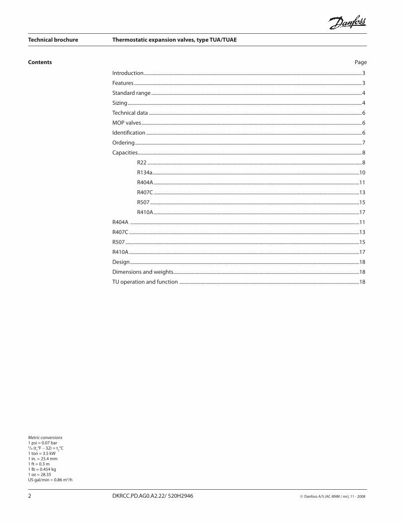
Contents Page
Introduction .................................................................................................................................................................................3
Features .........................................................................................................................................................................................3
Standard range ...........................................................................................................................................................................4
Sizing ..............................................................................................................................................................................................4
Technical data .............................................................................................................................................................................6
MOP valves ...................................................................................................................................................................................6
Identifi cation ...............................................................................................................................................................................6
Ordering ........................................................................................................................................................................................7
Capacities......................................................................................................................................................................................8
R22 ..............................................................................................................................................................................8
R134a ........................................................................................................................................................................10
R404A .......................................................................................................................................................................11
R407C .......................................................................................................................................................................13
R507 ..........................................................................................................................................................................15
R410A .......................................................................................................................................................................17
R404A ..........................................................................................................................................................................................11
R407C ...........................................................................................................................................................................................13
R507 ..............................................................................................................................................................................................15
R410A ...........................................................................................................................................................................................17
Design ..........................................................................................................................................................................................18
Dimensions and weights .......................................................................................................................................................18
TU operation and function ..................................................................................................................................................18

Technical brochure Thermostatic expansion valves, type TUA/TUAE
© Danfoss A/S (AC-BNM / mr), 11 - 2008 DKRCC.PD.AG0.A2.22/ 520H2946 3
Introduction
Danfoss now extends the new program of stainless steel thermostatic expansion valves. Type TUA/TUAE is available with interchangeable orifi ce assembly and removable strainer in a straightway design.The valves are off ered in rated capacities up to 4.5 TR (R22) and can be used in a wide range of applications:
Conventional refrigeration systems
Heat pump systems
Air conditioning systems
Specialty refrigeration appliances
Liquid chillers
Ice machines
Transport refrigeration
Features Interchangeable orifi ce assemblyFor easier stocking, capacity matching, and service
Bi-metal connectionsFast and easy soldering without the need for a wet cloth.
RefrigerantsR22, R134a, R404A, R407C, R507, R410A(for other refrigerants, contact Danfoss)
Bi-fl ow function (orifi ce 1 to 8)
Compact designSmall dimensions and light weight for compact installation.
Stainless steelHigh body strengthHigh corrosion resistanceHighly vibration-resistant, fl exible capillary tube
Precision Port designFour major features contributing to superior repeatable performance over an extended valve life:
Laser-welded power elementinsures diaphragm´s structural integrity and lengthens life.Precision-machined cone and bushingavoid the need for a packing gland.
Free-fl oating push-rodis self-aligning and eliminates binding.
Precision-machined cone and orifi ceaccurately meters refrigerant under all operating conditions.
Stainless steel capillary tubeTolerates more bending for easier in stal la ti on and longer life.Greater resistance to vibration during ope ra ti on.
Stainless steel bulbSelf-aligning for fast and easy installation; secures with a single strap or quick clip.More contact surface for better heat transfer.
Patented superheat adjustment device:Adjust with 5/32 in. Allen wrench.
Removable strainer 100 mesh removable strainer for easy servicing. Suitable for use with new POE oils.
Laser engravingDurable positive valve identifi cation; no labels to peel off over time.
Optional quick clip bulb fastener-For fast and easy installation.
Bleed orifi ces available on special request
The TUA/TUAE is made of stainless steel and therefore is especially well-suited to refrigeration systems where aggressive environments exist. The TUA/TUAE has been developed and designed especially for soldering into hermetic refrigeration systems.
This leafl et contains data and code numbers for our standard product program.Danfoss also off ers other stainless steel thermostatic expansion valves e.g. TUB/TUBE with fi xed orifi ce and TUC/TUCE with fi xed orifi ce and fi xed superheat setting.
For further information, please contact Danfoss.
Metric conversions1 ton = 3.5 kW
Technical brochure Thermostatic expansion valves, type TUA/TUAE
4 DKRCC.PD.AG0.A2.22/ 520H2946 © Danfoss A/S (AC-BNM / mr), 11 - 2008
Danfoss off ers the following standard range of thermostatic charges:Range N − 40 to +50°F without MOPRange N − 40 to +50°F, MOP 60°FRange NM − 40 to +25°F, MOP 32°FRange B1) − 75 to −15°F without MOPRange B1) − 75 to −15°F, MOP −4°F1) TU valves for range B are not supplied for R134a.
Static superheat (SS)(R22, R134a, R404A, R407C and R410A):Valves without MOP 9° FValves with MOP 7° F
Static superheat (SS) (R507):Valves without MOP 11° FValves with MOP 9.5° F
Standard range
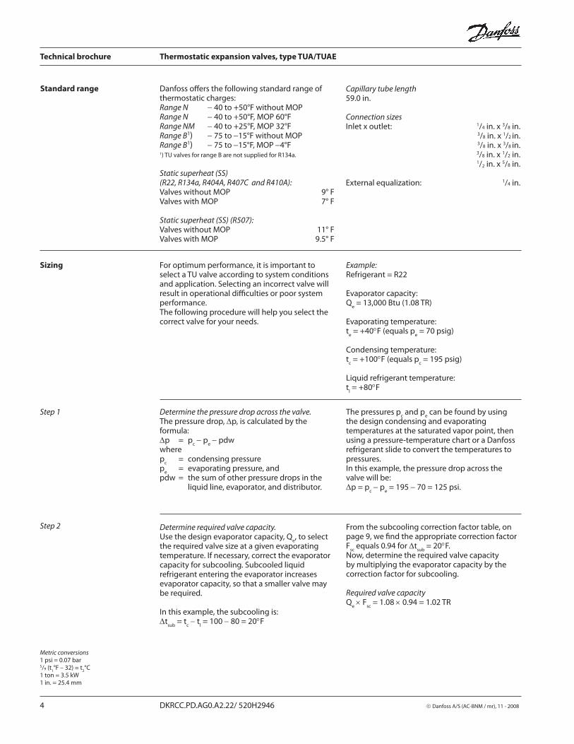
Sizing For optimum performance, it is important to select a TU valve according to system conditions and application. Selecting an incorrect valve will result in operational diffi culties or poor system performance.The following procedure will help you select the correct valve for your needs.
Example:Refrigerant = R22
Evaporator capacity:Q
e = 13,000 Btu (1.08 TR)
Evaporating temperature:t
e = +40°F (equals p
e = 70 psig)
Condensing temperature:t
c = +100°F (equals p
c = 195 psig)
Liquid refrigerant temperature:t
l = +80°F
Step 1 The pressures pc and p
e can be found by using
the design condensing and evaporating temperatures at the saturated vapor point, then using a pressure-temperature chart or a Danfoss refrigerant slide to convert the temperatures to pressures.In this example, the pressure drop across the valve will be:Δp = p
c − p
e = 195 − 70 = 125 psi.
Determine the pressure drop across the valve.The pressure drop, Δp, is calculated by the formula:Δp = p
c − p
e − pdw
wherep
c = condensing pressure
pe = evaporating pressure, and
pdw = the sum of other pressure drops in the liquid line, evaporator, and distributor.
Determine required valve capacity.Use the design evaporator capacity, Q
e, to select
the required valve size at a given evaporating temperature. If necessary, correct the evaporator capacity for subcooling. Subcooled liquid refrigerant entering the evaporator increases evaporator capacity, so that a smaller valve may be required.
In this example, the subcooling is:Δt
sub = t
c − t
l = 100 − 80 = 20°F
From the subcooling correction factor table, on page 9, we fi nd the appropriate correction factor F
sc equals 0.94 for Δt
sub = 20°F.
Now, determine the required valve capacity by multiplying the evaporator capacity by the correction factor for subcooling.
Required valve capacityQ
e × F
sc = 1.08 × 0.94 = 1.02 TR
Step 2
Metric conversions1 psi = 0.07 bar5/9 (t
1°F – 32) = t
2°C
1 ton = 3.5 kW1 in. = 25.4 mm
Capillary tube length59.0 in.
Connection sizesInlet x outlet: 1/4 in. x 3/8 in. 3/8 in. x 1/2
in.
3/8 in. x 3/8 in.
3/8 in. x 1/2 in. 1/2 in. x 5/8 in.
External equalization: 1/4 in.

Technical brochure Thermostatic expansion valves, type TUA/TUAE
© Danfoss A/S (AC-BNM / mr), 11 - 2008 DKRCC.PD.AG0.A2.22/ 520H2946 5
Note that the expansion valve capacity must be equal to or slightly more than the corrected evaporator capacity.In this sizing example, orifi ce 5 will be suitable.
Use the calculated valve capacity to select the corresponding orifi ce size from the capacity table for R22 as indicated below.
Range N: –40 → +50°F. Δtsub
= 10°F, OS = 7°F
TypeOrifi ce
no.
Pressure drop across valve ∆p psi
50 75 100 125 150 175 200 225
Evaporating temperature +40°F
TU
0 0.14 0.16 0.18 0.19 0.20 0.20 0.20 0.20
1 0.21 0.24 0.26 0.27 0.28 0.29 0.29 0.30
2 0.28 0.33 0.36 0.38 0.40 0.41 0.42 0.43
3 0.39 0.45 0.50 0.53 0.56 0.57 0.58 0.59
4 0.59 0.68 0.75 0.80 0.83 0.86 0.88 0.88
5 0.78 0.91 0.99 1.06 1.11 1.15 1.17 1.19
6 1.18 1.37 1.50 1.60 1.67 1.73 1.77 1.80
7 1.57 1.82 2.00 2.13 2.23 2.30 2.35 2.40
The extended capacity tables can be found on pages 8 to16.
Select a thermostatic charge.Danfoss off ers a universal wide range thermostatic charge, Range N, suited for most applications in the normal temperature range.
Ranges NM and B are available for special low temperature applications.
Step 5 Determine if external equalization is required.
Note! External equalization is always required if a distributor is used or if there is an appreciable diff erence in pressure from the valve outlet to the bulb location.
Finally, determine connection sizes, then fi nd the valve´s code number from the tables on page 7.
Step 4
Sizing (continued)
Step 3
Metric conversions1 psi = 0.07 bar5/9 (t
1°F – 32) = t
2°C
1 ton = 3.5 kW
Capacities (TR)
Technical brochure Thermostatic expansion valves, type TUA/TUAE
6 DKRCC.PD.AG0.A2.22/ 520H2946 © Danfoss A/S (AC-BNM / mr), 11 - 2008
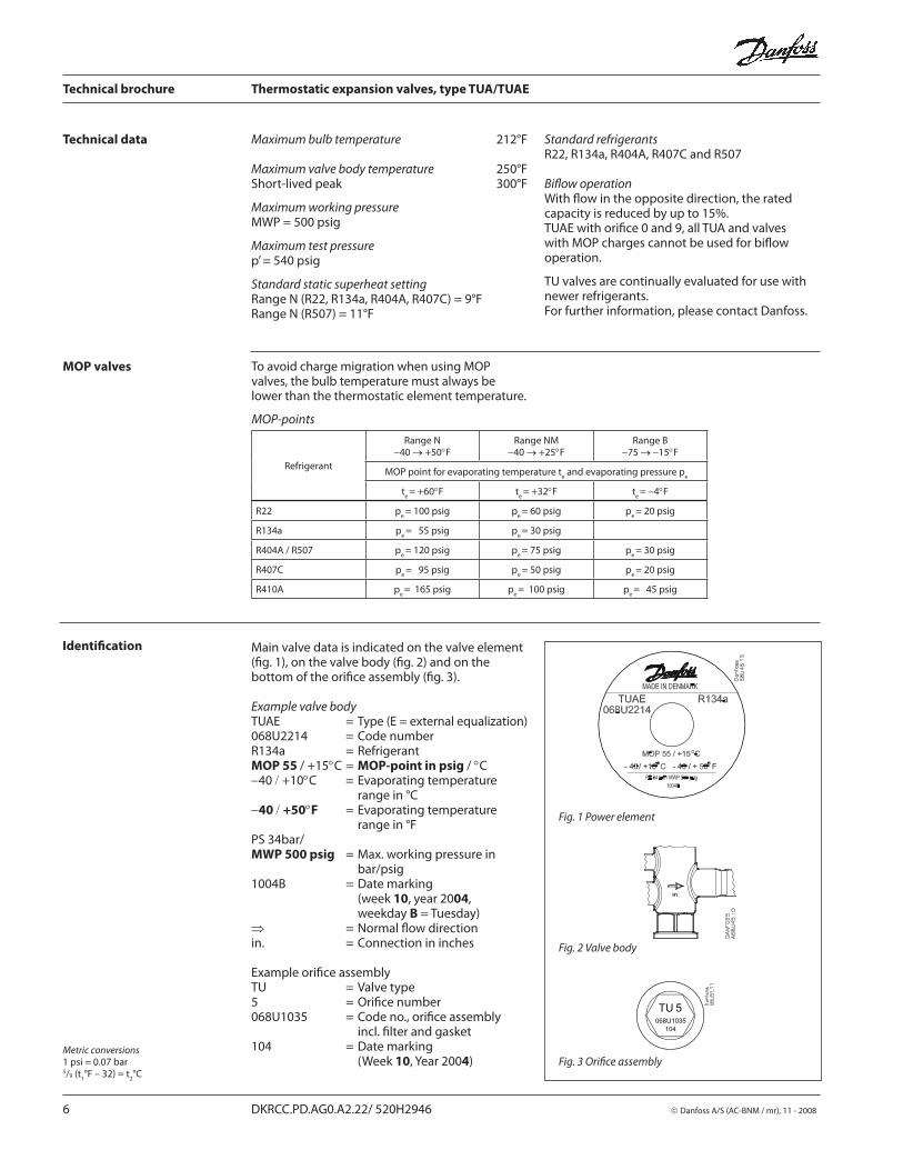
Maximum bulb temperature 212°F
Maximum valve body temperature 250°FShort-lived peak 300°F
Maximum working pressureMWP = 500 psig
Maximum test pressurep’ = 540 psig
Standard static superheat settingRange N (R22, R134a, R404A, R407C) = 9°FRange N (R507) = 11°F
Technical data
MOP-points
Refrigerant
Range N−40 → +50°F
Range NM−40 → +25°F
Range B−75 → −15°F
MOP point for evaporating temperature te and evaporating pressure p
e
te = +60°F t
e = +32°F t
e = −4°F
R22 pe = 100 psig p
e = 60 psig p
e = 20 psig
R134a pe = 55 psig p
e = 30 psig
R404A / R507 pe = 120 psig p
e = 75 psig p
e = 30 psig
R407C pe = 95 psig p
e = 50 psig p
e = 20 psig
R410A pe = 165 psig p
e = 100 psig p
e = 45 psig
Standard refrigerantsR22, R134a, R404A, R407C and R507
Bifl ow operationWith fl ow in the opposite direction, the rated capacity is reduced by up to 15%.TUAE with orifi ce 0 and 9, all TUA and valves with MOP charges cannot be used for bifl ow ope ra ti on.
TU valves are continually evaluated for use with newer refrigerants.For further information, please contact Danfoss.
Metric conversions1 psi = 0.07 bar5/9 (t
1°F – 32) = t
2°C
To avoid charge migration when using MOP valves, the bulb temperature must always be lower than the thermostatic element temperature.
Main valve data is indicated on the valve element (fi g. 1), on the valve body (fi g. 2) and on the bottom of the orifi ce assembly (fi g. 3).
Example valve bodyTUAE = Type (E = external equalization)068U2214 = Code numberR134a = RefrigerantMOP 55 / +15°C = MOP-point in psig / °C−40 / +10°C = Evaporating temperature
range in °C−40 / +50°F = Evaporating temperature
range in °FPS 34bar/MWP 500 psig = Max. working pressure in
bar/psig1004B = Date marking
(week 10, year 2004,weekday B = Tuesday)
⇒ = Normal fl ow directionin. = Connection in inches
Example orifi ce assemblyTU = Valve type5 = Orifi ce number068U1035 = Code no., orifi ce assembly
incl. fi lter and gasket104 = Date marking
(Week 10, Year 2004)
Identifi cation
Fig. 1 Power element
Fig. 2 Valve body
Fig. 3 Orifi ce assembly
MOP valves
Technical brochure Thermostatic expansion valves, type TUA/TUAE
© Danfoss A/S (AC-BNM / mr), 11 - 2008 DKRCC.PD.AG0.A2.22/ 520H2946 7
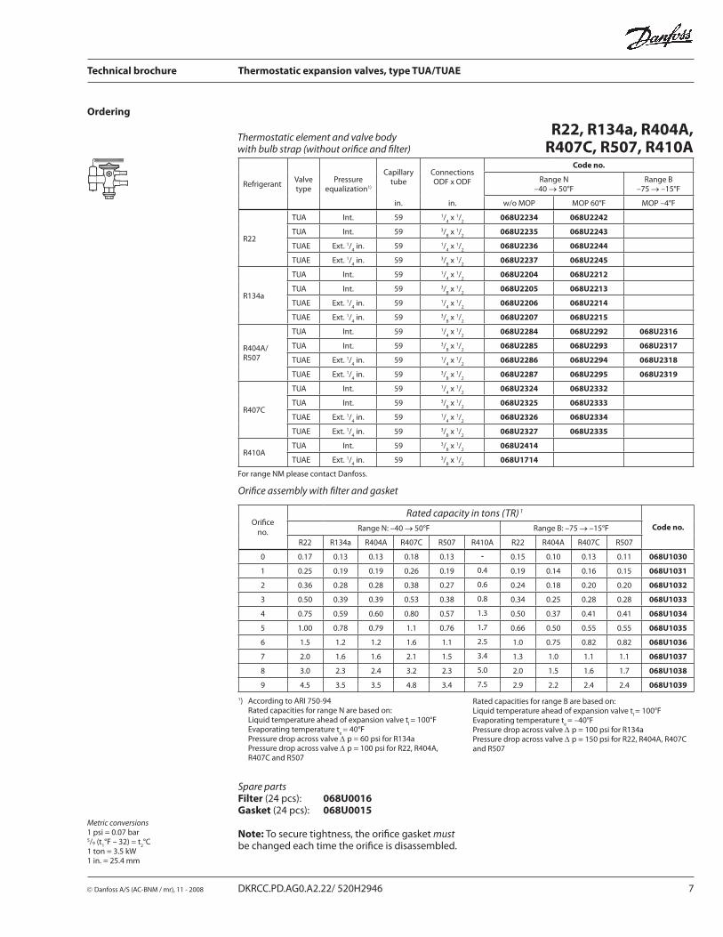
Ordering
1) According to ARI 750-94Rated capacities for range N are based on:Liquid temperature ahead of expansion valve t
l = 100°F
Evaporating temperature te = 40°F
Pressure drop across valve Δ p = 60 psi for R134aPressure drop across valve Δ p = 100 psi for R22, R404A, R407C and R507
Orifi ce assembly with fi lter and gasket
Spare partsFilter (24 pcs): 068U0016Gasket (24 pcs): 068U0015
Note: To secure tightness, the orifi ce gasket must be changed each time the orifi ce is disassembled.
Metric conversions1 psi = 0.07 bar5/9 (t
1°F – 32) = t
2°C
1 ton = 3.5 kW1 in. = 25.4 mm
R22, R134a, R404A, R407C, R507, R410A
Thermostatic element and valve body with bulb strap (without orifi ce and fi lter)
Rated capacities for range B are based on:Liquid temperature ahead of expansion valve t
l = 100°F
Evaporating temperature te = –40°F
Pressure drop across valve Δ p = 100 psi for R134aPressure drop across valve Δ p = 150 psi for R22, R404A, R407C and R507
For range NM please contact Danfoss.
RefrigerantValve type
Pressure equalization1)
Capillary tube
Connections ODF x ODF
Code no.
Range N–40 → 50°F
Range B–75 → –15°F
in. in. w/o MOP MOP 60°F MOP –4°F
R22
TUA Int. 59 1/4 x 1/
2068U2234 068U2242
TUA Int. 59 3/8 x 1/
2068U2235 068U2243
TUAE Ext. 1/4 in. 59 1/
4 x 1/
2068U2236 068U2244
TUAE Ext. 1/4 in. 59 3/
8 x 1/
2068U2237 068U2245
R134a
TUA Int. 59 1/4 x 1/
2068U2204 068U2212
TUA Int. 59 3/8 x 1/
2068U2205 068U2213
TUAE Ext. 1/4 in. 59 1/
4 x 1/
2068U2206 068U2214
TUAE Ext. 1/4 in. 59 3/
8 x 1/
2068U2207 068U2215
R404A/R507
TUA Int. 59 1/4 x 1/
2068U2284 068U2292 068U2316
TUA Int. 59 3/8 x 1/
2068U2285 068U2293 068U2317
TUAE Ext. 1/4 in. 59 1/
4 x 1/
2068U2286 068U2294 068U2318
TUAE Ext. 1/4 in. 59 3/
8 x 1/
2068U2287 068U2295 068U2319
R407C
TUA Int. 59 1/4 x 1/
2068U2324 068U2332
TUA Int. 59 3/8 x 1/
2068U2325 068U2333
TUAE Ext. 1/4 in. 59 1/
4 x 1/
2068U2326 068U2334
TUAE Ext. 1/4 in. 59 3/
8 x 1/
2068U2327 068U2335
R410ATUA Int. 59 3/
8 x 1/
2068U2414
TUAE Ext. 1/4 in. 59 3/
8 x 1/
2068U1714
Orifi ce
no.
Rated capacity in tons (TR) 1
Code no.Range N: –40 → 50°F Range B: –75 → –15°F
R22 R134a R404A R407C R507 R410A R22 R404A R407C R507
0 0.17 0.13 0.13 0.18 0.13 - 0.15 0.10 0.13 0.11 068U1030
1 0.25 0.19 0.19 0.26 0.19 0.4 0.19 0.14 0.16 0.15 068U1031
2 0.36 0.28 0.28 0.38 0.27 0.6 0.24 0.18 0.20 0.20 068U1032
3 0.50 0.39 0.39 0.53 0.38 0.8 0.34 0.25 0.28 0.28 068U1033
4 0.75 0.59 0.60 0.80 0.57 1.3 0.50 0.37 0.41 0.41 068U1034
5 1.00 0.78 0.79 1.1 0.76 1.7 0.66 0.50 0.55 0.55 068U1035
6 1.5 1.2 1.2 1.6 1.1 2.5 1.0 0.75 0.82 0.82 068U1036
7 2.0 1.6 1.6 2.1 1.5 3.4 1.3 1.0 1.1 1.1 068U1037
8 3.0 2.3 2.4 3.2 2.3 5.0 2.0 1.5 1.6 1.7 068U1038
9 4.5 3.5 3.5 4.8 3.4 7.5 2.9 2.2 2.4 2.4 068U1039

Technical brochure Thermostatic expansion valves, type TUA/TUAE
8 DKRCC.PD.AG0.A2.22/ 520H2946 © Danfoss A/S (AC-BNM / mr), 11 - 2008
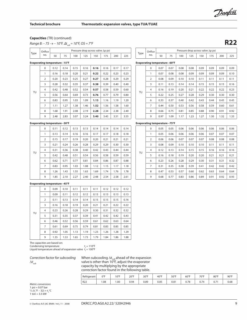
Capacities (TR)
R22
Refrigerant 0°F 10°F 20°F 30°F 40°F 50°F 60°F 70°F 80°F 90°F
R22 1.08 1.00 0.94 0.89 0.85 0.81 0.78 0.74 0.71 0.68
When subcooling Δtsub ahead of the expansion valve
is other than 10°F, adjust the evaporator
capacity by multiplying by the appropriate correction factor found in the following table.
Correction factor for subcooling Δt
sub
Metric conversions1 psi = 0.07 bar5/9 (t
1°F – 32) = t
2°C
1 ton = 3.5 kW
Range N: –40 → +50°F. Δtsub
= 10°F, OS = 7°F
The capacities are based on:Condensing temperature t
c = 110°F
Liquid temperature ahead of expansion valve tl = 100°F
TypeOrifi ce
no.
Pressure drop across valve ∆p psiType
Orifi ce no.
Pressure drop across valve Δp psi
50 75 100 125 150 175 200 225 50 75 100 125 150 175 200 225
Evaporating temperature +50°F Evaporating temperature 0°F
TU
0 0.15 0.17 0.18 0.19 0.20 0.20 0.21 0.21
TU
0 0.12 0.13 0.14 0.15 0.15 0.16 0.16 0.16
1 0.22 0.25 0.27 0.29 0.30 0.30 0.31 0.31 1 0.14 0.16 0.18 0.19 0.20 0.20 0.21 0.21
2 0.31 0.36 0.40 0.43 0.44 0.46 0.47 0.48 2 0.17 0.20 0.22 0.23 0.24 0.26 0.25 0.26
3 0.43 0.50 0.55 0.59 0.61 0.63 0.65 0.66 3 0.24 0.28 0.30 0.32 0.34 0.35 0.35 0.36
4 0.65 0.76 0.83 0.89 0.93 0.96 0.98 1.00 4 0.36 0.41 0.45 0.48 0.50 0.51 0.52 0.53
5 0.87 1.01 1.11 1.18 1.23 1.27 1.30 1.32 5 0.48 0.55 0.60 0.64 0.66 0.68 0.70 0.70
6 1.30 1.51 1.67 1.78 1.86 1.93 1.96 2.00 6 0.72 0.83 0.90 0.95 0.99 1.02 1.04 1.05
7 1.73 2.01 2.22 2.36 2.48 2.56 2.61 2.66 7 0.96 1.10 1.20 1.28 1.33 1.37 1.39 1.41
8 2.58 3.00 3.31 3.53 3.69 3.81 3.90 3.97 8 1.45 1.67 1.81 1.92 2.00 2.06 2.10 2.12
9 3.87 4.52 4.97 5.29 5.53 5.71 5.84 5.93 9 2.14 2.46 2.68 2.83 2.95 3.03 3.09 3.12
Evaporating temperature +40°F Evaporating temperature −20°F
TU
0 0.14 0.16 0.18 0.19 0.20 0.20 0.20 0.20
TU
0 0.10 0.11 0.12 0.12 0.13 0.13 0.13 0.13
1 0.21 0.24 0.26 0.27 0.28 0.29 0.29 0.30 1 0.11 0.13 0.14 0.14 0.15 0.15 0.16 0.16
2 0.28 0.33 0.36 0.38 0.40 0.41 0.42 0.43 2 0.13 0.15 0.16 0.17 0.18 0.18 0.18 0.19
3 0.39 0.45 0.50 0.53 0.56 0.57 0.58 0.59 3 0.18 0.21 0.23 0.24 0.25 0.25 0.26 0.26
4 0.59 0.68 0.75 0.80 0.83 0.86 0.88 0.88 4 0.27 0.31 0.33 0.35 0.36 0.37 0.38 0.38
5 0.78 0.91 0.99 1.06 1.11 1.15 1.17 1.19 5 0.36 0.41 0.44 0.47 0.49 0.50 0.51 0.51
6 1.18 1.37 1.50 1.60 1.67 1.73 1.77 1.80 6 0.53 0.61 0.66 0.70 0.72 0.74 0.76 0.76
7 1.57 1.82 2.00 2.13 2.23 2.30 2.35 2.40 7 0.71 0.81 0.88 0.93 0.97 1.00 1.01 1.02
8 2.34 2.72 2.99 3.19 3.33 3.44 3.51 3.57 8 1.08 1.23 1.34 1.41 1.46 1.50 1.53 1.55
9 3.52 4.06 4.46 4.76 4.97 5.13 5.25 5.37 9 1.58 1.80 1.96 2.07 2.14 2.20 2.25 2.26
Evaporating temperature +20°F Evaporating temperature −40°F
TU
0 0.13 0.15 0.16 0.17 0.17 0.18 0.18 0.18
TU
0 0.07 0.08 0.09 0.10 0.10 0.10 0.10 0.10
1 0.18 0.20 0.22 0.23 0.24 0.25 0.25 0.26 1 0.08 0.09 0.10 0.10 0.11 0.11 0.11 0.11
2 0.23 0.26 0.28 0.30 0.32 0.33 0.33 0.34 2 0.09 0.11 0.11 0.12 0.12 0.13 0.13 0.13
3 0.31 0.36 0.40 0.42 0.44 0.45 0.46 0.47 3 0.13 0.15 0.16 0.17 0.17 0.18 0.18 0.18
4 0.47 0.54 0.59 0.63 0.66 0.67 0.69 0.70 4 0.19 0.22 0.23 0.25 0.26 0.26 0.27 0.27
5 0.62 0.72 0.79 0.84 0.87 0.90 0.92 0.93 5 0.26 0.29 0.31 0.33 0.34 0.35 0.36 0.36
6 0.93 1.08 1.18 1.26 1.31 1.35 1.38 1.40 6 0.38 0.43 0.47 0.49 0.51 0.52 0.53 0.53
7 1.25 1.44 1.58 1.68 1.75 1.80 1.84 1.87 7 0.51 0.58 0.63 0.66 0.68 0.70 0.71 0.72
8 1.88 2.17 2.37 2.52 2.63 2.71 2.77 2.80 8 0.77 0.88 0.95 1.00 1.04 1.06 1.07 1.08
9 2.97 3.22 3.51 3.74 3.90 4.02 4.10 4.16 9 1.12 1.28 1.38 1.45 1.50 1.54 1.56 1.58
Technical brochure Thermostatic expansion valves, type TUA/TUAE
© Danfoss A/S (AC-BNM / mr), 11 - 2008 DKRCC.PD.AG0.A2.22/ 520H2946 9
TypeOrifi ce
no.
Pressure drop across valve Δp psiType
Orifi ce no.
Pressure drop across valve Δp psi
50 75 100 125 150 175 200 225 50 75 100 125 150 175 200 225
Evaporating temperature –15°F Evaporating temperature –60°F
TU
0 0.12 0.14 0.15 0.16 0.16 0.16 0.17 0.17
TU
0 0.07 0.07 0.08 0.08 0.09 0.09 0.09 0.09
1 0.16 0.18 0.20 0.21 0.22 0.22 0.23 0.23 1 0.07 0.08 0.08 0.09 0.09 0.09 0.09 0.10
2 0.20 0.23 0.25 0.27 0.27 0.28 0.29 0.29 2 0.08 0.09 0.10 0.10 0.11 0.11 0.11 0.11
3 0.28 0.32 0.35 0.37 0.38 0.39 0.40 0.40 3 0.11 0.13 0.14 0.14 0.15 0.15 0.15 0.16
4 0.42 0.48 0.52 0.54 0.57 0.58 0.59 0.60 4 0.16 0.19 0.20 0.21 0.22 0.22 0.22 0.23
5 0.56 0.64 0.69 0.73 0.76 0.77 0.79 0.80 5 0.22 0.25 0.27 0.28 0.29 0.30 0.30 0.30
6 0.83 0.95 1.03 1.09 1.13 1.16 1.19 1.20 6 0.33 0.37 0.40 0.42 0.43 0.44 0.45 0.45
7 1.11 1.27 1.38 1.46 1.52 1.56 1.58 1.60 7 0.44 0.50 0.53 0.56 0.58 0.59 0.60 0.61
8 1.68 1.91 2.08 2.19 2.28 2.34 2.38 2.40 8 0.66 0.75 0.81 0.85 0.88 0.90 0.91 0.92
9 2.48 2.83 3.07 3.24 3.40 3.45 3.51 3.55 9 0.97 1.09 1.17 1.23 1.27 1.30 1.32 1.33
Evaporating temperature –30°F Evaporating temperature –75°F
TU
0 0.11 0.12 0.13 0.13 0.14 0.14 0.14 0.14
TU
0 0.05 0.05 0.06 0.06 0.06 0.06 0.06 0.06
1 0.13 0.14 0.16 0.16 0.17 0.17 0.18 0.18 1 0.05 0.06 0.06 0.06 0.06 0.07 0.07 0.07
2 0.15 0.17 0.19 0.20 0.20 0.21 0.21 0.21 2 0.06 0.06 0.07 0.07 0.07 0.08 0.08 0.08
3 0.21 0.24 0.26 0.28 0.29 0.29 0.30 0.30 3 0.08 0.09 0.10 0.10 0.10 0.11 0.11 0.11
4 0.31 0.36 0.38 0.40 0.42 0.43 0.44 0.44 4 0.12 0.13 0.14 0.15 0.15 0.16 0.16 0.16
5 0.42 0.48 0.51 0.54 0.56 0.58 0.59 0.59 5 0.16 0.18 0.19 0.20 0.20 0.21 0.21 0.21
6 0.62 0.71 0.77 0.81 0.84 0.86 0.87 0.88 6 0.23 0.26 0.28 0.29 0.30 0.31 0.31 0.32
7 0.83 0.95 1.03 1.08 1.12 1.15 1.17 1.18 7 0.31 0.35 0.38 0.39 0.41 0.42 0.42 0.42
8 1.26 1.43 1.55 1.63 1.69 1.74 1.76 1.78 8 0.47 0.53 0.57 0.60 0.62 0.63 0.64 0.64
9 1.85 2.10 2.27 2.40 2.48 2.54 2.58 2.61 9 0.68 0.77 0.83 0.86 0.89 0.91 0.92 0.93
Evaporating temperature –45°F
TU
0 0.09 0.10 0.11 0.11 0.11 0.12 0.12 0.12
1 0.09 0.11 0.12 0.12 0.13 0.13 0.13 0.13
2 0.11 0.13 0.14 0.14 0.15 0.15 0.15 0.16
3 0.16 0.18 0.19 0.20 0.21 0.21 0.22 0.22
4 0.23 0.26 0.28 0.29 0.30 0.31 0.32 0.32
5 0.31 0.35 0.37 0.39 0.41 0.42 0.42 0.43
6 0.46 0.52 0.56 0.59 0.61 0.62 0.63 0.64
7 0.61 0.69 0.75 0.79 0.81 0.83 0.85 0.85
8 0.92 1.05 1.13 1.19 1.23 1.26 1.28 1.29
9 1.35 1.53 1.65 1.73 1.79 1.84 1.86 1.88
Range B: – 75 → – 10°F. ∆tsub
= 10°F, OS = 7°F R22
Refrigerant 0°F 10°F 20°F 30°F 40°F 50°F 60°F 70°F 80°F 90°F
R22 1.08 1.00 0.94 0.89 0.85 0.81 0.78 0.74 0.71 0.68
When subcooling Δtsub ahead of the expansion
valve is other than 10°F, adjust the evaporator
capacity by multiplying by the appropriate correction factor found in the following table.
Correction factor for subcooling Δt
sub
Metric conversions1 psi = 0.07 bar5/9 (t
1°F – 32) = t
2°C
1 ton = 3.5 kW
The capacities are based on:Condensing temperature t
c = 110°F
Liquid temperature ahead of expansion valve tl = 100°F
Capacities (TR) (continued)

Technical brochure Thermostatic expansion valves, type TUA/TUAE
10 DKRCC.PD.AG0.A2.22/ 520H2946 © Danfoss A/S (AC-BNM / mr), 11 - 2008
TypeOrifi ce
no.
Pressure drop across valve Δp psiType
Orifi ce no.
Pressure drop across valve Δp psi
40 60 80 100 120 140 160 180 40 60 80 100 120 140 160 180
Evaporating temperature +50°F Evaporating temperature 0°F
TU
0 0.12 0.14 0.14 0.15 0.15 0.16
TU
0 0.09 0.10 0.10 0.11 0.11 0.11
1 0.18 0.21 0.22 0.23 0.23 0.24 1 0.10 0.12 0.13 0.13 0.14 0.14
2 0.26 0.30 0.33 0.34 0.36 0.36 2 0.13 0.14 0.15 0.16 0.16 0.17
3 0.36 0.42 0.45 0.47 0.49 0.50 3 0.18 0.20 0.21 0.22 0.23 0.23
4 0.55 0.63 0.68 0.72 0.74 0.76 4 0.26 0.29 0.31 0.33 0.34 0.34
5 0.73 0.84 0.91 0.96 0.99 1.01 5 0.35 0.39 0.42 0.44 0.45 0.46
6 1.10 1.26 1.38 1.45 1.50 1.53 6 0.52 0.59 0.63 0.66 0.67 0.68
7 1.46 1.68 1.83 1.93 1.99 2.04 7 0.70 0.78 0.84 0.88 0.90 0.91
8 2.18 2.50 2.72 2.86 2.97 3.03 8 1.05 1.18 1.27 1.32 1.36 1.37
9 3.28 3.75 4.10 4.28 4.41 4.52 9 1.54 1.74 1.86 1.94 1.99 2.02
Evaporating temperature +40°F Evaporating temperature −20°F
TU
0 0.12 0.13 0.14 0.14 0.15 0.15
TU
0 0.07 0.08 0.08 0.08 0.08 0.09
1 0.17 0.19 0.21 0.21 0.22 0.22 1 0.07 0.08 0.09 0.09 0.09 0.09
2 0.23 0.27 0.29 0.30 0.31 0.32 2 0.09 0.10 0.10 0.11 0.11 0.11
3 0.32 0.37 0.40 0.42 0.43 0.44 3 0.12 0.14 0.14 0.15 0.15 0.15
4 0.49 0.56 0.60 0.63 0.65 0.66 4 0.18 0.20 0.21 0.22 0.22 0.23
5 0.73 0.74 0.80 0.84 0.87 0.89 5 0.24 0.26 0.28 0.29 0.30 0.30
6 0.98 1.12 1.21 1.27 1.31 1.34 6 0.35 0.39 0.42 0.44 0.45 0.45
7 1.30 1.49 1.61 1.68 1.75 1.78 7 0.47 0.53 0.56 0.59 0.60 0.60
8 1.94 2.23 2.40 2.53 2.61 2.66 8 0.71 0.80 0.85 0.88 0.90 0.91
9 2.90 3.32 3.59 3.76 3.88 3.96 9 1.04 1.17 1.24 1.28 1.32 1.33
Evaporating temperature +20°F Evaporating temperature −40°F
TU
0 0.10 0.12 0.12 0.13 0.13 0.13
TU
0 0.05 0.05 0.05 0.06 0.06 0.06
1 0.14 0.16 0.17 0.18 0.18 0.18 1 0.05 0.05 0.06 0.06 0.06 0.06
2 0.18 0.20 0.22 0.23 0.23 0.24 2 0.06 0.06 0.07 0.07 0.07 0.07
3 0.25 0.28 0.30 0.31 0.32 0.33 3 0.08 0.09 0.09 0.10 0.10 0.10
4 0.37 0.42 0.45 0.47 0.48 0.49 4 0.11 0.13 0.14 0.14 0.14 0.14
5 0.49 0.55 0.60 0.62 0.64 0.65 5 0.15 0.17 0.18 0.19 0.19 0.19
6 0.73 0.83 0.89 0.94 0.96 0.98 6 0.23 0.25 0.27 0.28 0.28 0.29
7 0.98 1.11 1.19 1.25 1.29 1.31 7 0.31 0.34 0.36 0.37 0.38 0.38
8 1.47 1.67 1.80 1.88 1.93 1.97 8 0.46 0.52 0.55 0.57 0.58 0.58
9 2.18 2.47 2.65 2.78 2.68 2.94 9 0.67 0.75 0.79 0.82 0.84 0.84
R134aRange N: –40 → +50°F. Δtsub
= 10°F, OS = 7°F
Refrigerant 0°F 10°F 20°F 30°F 40°F 50°F 60°F 70°F 80°F 90°F
R134a 1.10 1.00 0.93 0.88 0.82 0.78 0.74 0.70 0.67 0.64
Correction factor for subcooling Δt
sub
When subcooling Δtsub ahead of the expansion
valve is other than 10°F, adjust the evaporator
capacity by multiplying by the appropriate correction factor found in the following table.
Metric conversions1 psi = 0.07 bar5/9 (t
1°F – 32) = t
2°C
1 ton = 3.5 kW
The capacities are based on:Condensing temperature t
c = 110°F
Liquid temperature ahead of expansion valve tl = 100°F
Capacities (TR) (continued)
Technical brochure Thermostatic expansion valves, type TUA/TUAE
© Danfoss A/S (AC-BNM / mr), 11 - 2008 DKRCC.PD.AG0.A2.22/ 520H2946 11
TypeOrifi ce
no.
Pressure drop across valve Δp psiType
Orifi ceno.
Pressure drop across valve Δp psi
75 100 125 150 175 200 225 250 75 100 125 150 175 200 225 250
Evaporating temperature +50°F Evaporating temperature 0°F
TU
0 0.12 0.13 0.14 0.14 0.14 0.13 0.13 0.13
TU
0 0.10 0.11 0.11 0.11 0.11 0.11 0.11 0.10
1 0.19 0.20 0.21 0.21 0.21 0.20 0.20 0.19 1 0.13 0.14 0.14 0.15 0.15 0.15 0.14 0.14
2 0.28 0.30 0.31 0.32 0.32 0.32 0.31 0.30 2 0.16 0.17 0.18 0.18 0.18 0.18 0.18 0.17
3 0.38 0.41 0.43 0.44 0.44 0.44 0.43 0.42 3 0.23 0.24 0.25 0.25 0.25 0.25 0.25 0.24
4 0.59 0.63 0.65 0.67 0.67 0.67 0.65 0.64 4 0.34 0.36 0.37 0.37 0.37 0.37 0.36 0.35
5 0.78 0.83 0.87 0.89 0.89 0.88 0.88 0.85 5 0.45 0.48 0.49 0.50 0.50 0.49 0.48 0.47
6 1.17 1.26 1.31 1.34 1.35 1.34 1.32 1.28 6 0.67 0.72 0.74 0.75 0.75 0.74 0.73 0.71
7 1.56 1.68 1.74 1.78 1.78 1.78 1.75 1.70 7 0.90 0.96 0.99 1.00 1.00 0.99 0.97 0.94
8 2.32 2.49 2.60 2.65 3.66 2.64 2.60 2.53 8 1.36 1.44 1.49 1.51 1.51 1.48 1.46 1.42
9 3.49 3.74 3.90 4.00 3.99 3.95 3.89 3.79 9 2.00 2.13 2.20 2.23 2.22 2.20 2.15 2.09
Evaporating temperature +40°F Evaporating temperature −20°F
TU
0 0.12 0.13 0.13 0.13 0.13 0.13 0.13 0.13
TU
0 0.09 0.09 0.09 0.09 0.09 0.09 0.09 0.09
1 0.18 0.19 0.20 0.20 0.20 0.20 0.19 0.19 1 0.10 0.11 0.11 0.11 0.11 0.11 0.11 0.10
2 0.26 0.28 0.29 0.29 0.29 0.29 0.29 0.28 2 0.12 0.13 0.13 0.13 0.13 0.13 0.13 0.12
3 0.35 0.38 0.40 0.40 0.40 0.40 0.39 0.39 3 0.17 0.18 0.19 0.19 0.19 0.18 0.18 0.17
4 0.54 0.58 0.60 0.61 0.61 0.61 0.60 0.58 4 0.25 0.27 0.27 0.28 0.27 0.27 0.26 0.26
5 0.71 0.76 0.79 0.81 0.81 0.81 0.79 0.77 5 0.34 0.36 0.36 0.37 0.37 0.36 0.35 0.34
6 1.07 1.15 1.20 1.22 1.23 1.22 1.20 1.17 6 0.50 0.53 0.54 0.55 0.55 0.54 0.53 0.51
7 1.43 1.53 1.59 1.63 1.63 1.61 1.60 1.56 7 0.67 0.71 0.73 0.74 0.73 0.72 0.71 0.68
8 2.13 2.29 2.38 2.43 2.44 2.42 2.37 2.31 8 1.01 1.07 1.10 1.11 1.10 1.09 1.06 1.03
9 3.20 3.41 3.56 3.62 3.64 3.61 3.55 3.46 9 1.49 1.57 1.61 1.63 1.62 1.59 1.56 1.51
Evaporating temperature +20°F Evaporating temperature −40°F
TU
0 0.11 0.12 0.12 0.12 0.12 0.12 0.12 0.12
TU
0 0.07 0.07 0.07 0.07 0.07 0.07 0.07 0.07
1 0.16 0.17 0.18 0.18 0.18 0.17 0.17 0.17 1 0.07 0.08 0.08 0.08 0.08 0.08 0.08 0.07
2 0.21 0.22 0.23 0.24 0.23 0.23 0.23 0.22 2 0.09 0.09 0.09 0.09 0.09 0.09 0.09 0.09
3 0.29 0.31 0.32 0.33 0.33 0.32 0.32 0.31 3 0.12 0.13 0.13 0.13 0.13 0.13 0.13 0.12
4 0.44 0.46 0.48 0.49 0.49 0.49 0.48 0.46 4 0.18 0.19 0.19 0.19 0.19 0.19 0.18 0.18
5 0.58 0.62 0.64 0.65 0.65 0.65 0.64 0.62 5 0.24 0.25 0.26 0.26 0.26 0.25 0.26 0.24
6 0.87 0.93 0.96 0.98 0.98 0.97 0.96 0.93 6 0.36 0.37 0.38 0.39 0.38 0.38 0.36 0.35
7 1.16 1.24 1.29 1.31 1.31 1.30 1.28 1.24 7 0.48 0.50 0.51 0.52 0.51 0.50 0.49 0.47
8 1.74 1.86 1.93 1.97 1.96 1.94 1.91 1.86 8 0.72 0.76 0.78 0.78 0.77 0.76 0.74 0.71
9 2.59 2.77 2.87 2.91 2.91 2.89 2.83 2.76 9 1.06 1.11 1.14 1.14 1.13 1.11 1.08 1.04
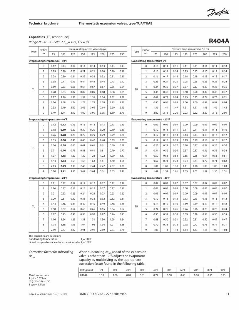
R404A Capacities (TR) (continued)
Refrigerant 0°F 10°F 20°F 30°F 40°F 50°F 60°F 70°F 80°F 90°F
R404A 1.18 1.00 0.89 0.81 0.74 0.68 0.63 0.60 0.56 0.53
Correction factor for subcooling ∆t
sub
When subcooling Δtsub ahead of the expansion
valve is other than 10°F, adjust the evaporator
capacity by multiplying by the appropriate correction factor found in the following table.
Metric conversions1 psi = 0.07 bar5/9 (t
1°F – 32) = t
2°C
1 ton = 3.5 kW
The capacities are based on:Condensing temperature t
c = 110°F
Liquid temperature ahead of expansion valve tl = 100°F
Range N: –40 → +50°F. Δtsub
= 10°F, OS = 7°F
Technical brochure Thermostatic expansion valves, type TUA/TUAE
12 DKRCC.PD.AG0.A2.22/ 520H2946 © Danfoss A/S (AC-BNM / mr), 11 - 2008
TypeOrifi ce
no.
Pressure drop across valve Δp psiType
Orifi ce no.
Pressure drop across valve Δp psi
50 75 100 125 150 175 200 225 50 75 100 125 150 175 200 225
Evaporating temperature –15°F Evaporating temperature −60°F
TU
0 0.10 0.11 0.11 0.12 0.12 0.12 0.11 0.11
TU
0 0.06 0.06 0.07 0.07 0.07 0.07 0.06 0.06
1 0.14 0.15 0.16 0.16 0.16 0.16 0.16 0.16 1 0.06 0.07 0.07 0.07 0.07 0.07 0.07 0.07
2 0.17 0.19 0.20 0.21 0.21 0.21 0.21 0.20 2 0.07 0.08 0.08 0.08 0.08 0.08 0.08 0.08
3 0.24 0.27 0.28 0.29 0.29 0.29 0.29 0.28 3 0.10 0.11 0.11 0.12 0.12 0.11 0.11 0.11
4 0.36 0.40 0.42 0.43 0.44 0.43 0.43 0.42 4 0.15 0.16 0.17 0.17 0.17 0.17 0.16 0.16
5 0.48 0.53 0.56 0.58 0.58 0.58 0.57 0.56 5 0.20 0.21 0.22 0.23 0.23 0.22 0.22 0.21
6 0.71 0.80 0.84 0.87 0.88 0.87 0.86 0.84 6 0.29 0.32 0.33 0.34 0.34 0.33 0.33 0.32
7 0.95 1.06 1.13 1.16 1.17 1.17 1.15 1.12 7 0.39 0.43 0.45 0.45 0.45 0.45 0.44 0.42
8 1.43 1.60 1.69 1.73 1.75 1.74 1.72 1.68 8 0.59 0.65 0.68 0.69 0.69 0.68 0.66 0.64
9 2.14 2.37 2.50 2.57 2.59 2.58 2.54 2.48 9 0.86 0.94 0.98 1.00 1.00 0.99 0.96 0.93
Evaporating temperature –30°F Evaporating temperature –75°F
TU
0 0.09 0.10 0.10 0.10 0.10 0.10 0.10 0.10
TU
0 0.04 0.05 0.05 0.05 0.05 0.05 0.05 0.04
1 0.11 0.12 0.13 0.13 0.13 0.13 0.13 0.12 1 0.04 0.05 0.05 0.05 0.05 0.05 0.05 0.05
2 0.13 0.15 0.15 0.16 0.16 0.16 0.16 0.15 2 0.05 0.06 0.06 0.06 0.06 0.06 0.06 0.05
3 0.18 0.20 0.22 0.22 0.22 0.22 0.22 0.21 3 0.07 0.08 0.08 0.08 0.08 0.08 0.08 0.07
4 0.27 0.30 0.32 0.32 0.33 0.33 0.32 0.31 4 0.10 0.11 0.12 0.12 0.12 0.12 0.11 0.11
5 0.37 0.40 0.43 0.44 0.44 0.44 0.43 0.42 5 0.14 0.15 0.16 0.16 0.16 0.16 0.15 0.15
6 0.54 0.60 0.64 0.65 0.66 0.65 0.64 0.62 6 0.21 0.22 0.23 0.24 0.23 0.23 0.22 0.22
7 0.73 0.81 0.85 0.87 0.88 0.87 0.86 0.84 7 0.28 0.30 0.31 0.32 0.32 0.31 0.30 0.29
8 1.10 1.22 1.28 1.31 1.32 1.31 1.29 1.26 8 0.42 0.45 0.47 0.48 0.48 0.47 0.46 0.44
9 1.62 1.79 1.89 1.93 1.94 1.93 1.89 1.85 9 0.61 0.66 0.69 0.69 0.69 0.68 0.66 0.64
Evaporating temperature –45°F
TU
0 0.07 0.08 0.08 0.08 0.08 0.08 0.08 0.08
1 0.08 0.09 0.10 0.10 0.10 0.10 0.10 0.09
2 0.10 0.11 0.11 0.12 0.12 0.12 0.11 0.11
3 0.14 0.15 0.16 0.16 0.16 0.16 0.16 0.15
4 0.20 0.22 0.23 0.24 0.24 0.24 0.23 0.23
5 0.27 0.30 0.31 0.32 0.32 0.32 0.31 0.30
6 0.40 0.44 0.47 0.48 0.48 0.47 0.46 0.45
7 0.54 0.60 0.63 0.64 0.64 0.63 0.62 0.60
8 0.82 0.90 0.94 0.96 0.97 0.96 0.94 0.91
9 1.20 1.32 1.38 1.41 1.41 1.40 1.37 1.33
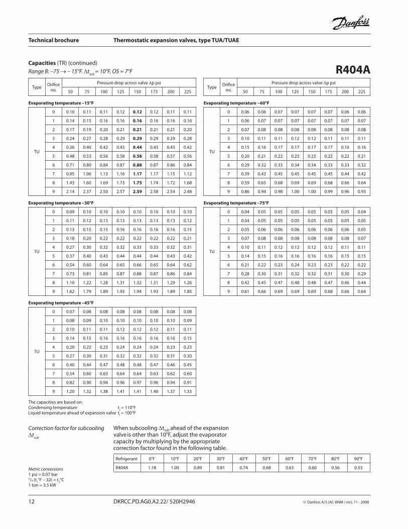
R404A Capacities (TR) (continued)
Correction factor for subcooling Δt
sub
Refrigerant 0°F 10°F 20°F 30°F 40°F 50°F 60°F 70°F 80°F 90°F
R404A 1.18 1.00 0.89 0.81 0.74 0.68 0.63 0.60 0.56 0.53
When subcooling Δtsub ahead of the expansion
valve is other than 10°F, adjust the evaporator
capacity by multiplying by the appropriate correction factor found in the following table.
Metric conversions1 psi = 0.07 bar5/9 (t
1°F – 32) = t
2°C
1 ton = 3.5 kW
The capacities are based on:Condensing temperature t
c = 110°F
Liquid temperature ahead of expansion valve tl = 100°F
Range B: –75 → – 15°F. Δtsub
= 10°F, OS = 7°F

Technical brochure Thermostatic expansion valves, type TUA/TUAE
© Danfoss A/S (AC-BNM / mr), 11 - 2008 DKRCC.PD.AG0.A2.22/ 520H2946 13
TypeOrifi ce
no.
Pressure drop across valve Δp psiType
Orifi ce no.
Pressure drop across valve Δp psi
50 75 100 125 150 175 200 225 50 75 100 125 150 175 200 225
Evaporating temperature +50°F Evaporating temperature 0°F
TU
0 0.15 0.17 0.18 0.19 0.20 0.20 0.20 0.20
TU
0 0.12 0.13 0.14 0.14 0.15 0.15 0.15 0.15
1 0.22 0.25 0.27 0.28 0.29 0.30 0.30 0.30 1 0.14 0.16 0.17 0.18 0.19 0.19 0.19 0.19
2 0.32 0.36 0.40 0.42 0.43 0.44 0.45 0.45 2 0.17 0.19 0.21 0.22 0.23 0.23 0.23 0.23
3 0.43 0.50 0.55 0.58 0.60 0.61 0.62 0.62 3 0.24 0.27 0.29 0.31 0.32 0.32 0.32 0.32
4 0.66 0.76 0.83 0.88 0.91 0.92 0.94 0.94 4 0.35 0.40 0.43 0.45 0.47 0.47 0.48 0.48
5 0.88 1.01 1.10 1.16 1.20 1.23 1.24 1.25 5 0.47 0.54 0.58 0.61 0.62 0.63 0.64 0.64
6 1.32 1.52 1.66 1.76 1.82 1.85 1.88 1.89 6 0.71 0.80 0.86 0.90 0.93 0.95 0.95 0.95
7 1.76 2.02 2.21 2.33 2.42 2.46 2.50 2.51 7 0.94 1.07 1.16 1.21 1.25 1.27 1.28 1.28
8 2.62 3.02 3.31 3.48 3.60 3.69 3.72 3.74 8 1.42 1.62 1.74 1.83 1.88 1.91 1.92 1.92
9 3.93 4.54 4.93 5.22 5.39 5.51 5.57 5.59 9 2.09 2.38 2.57 2.69 2.76 2.81 2.83 2.83
Evaporating temperature +40°F Evaporating temperature −20°F
TU
0 0.15 0.16 0.18 0.18 0.19 0.19 0.19 0.19
TU
0 0.10 0.11 0.11 0.12 0.12 0.12 0.12 0.12
1 0.21 0.24 0.26 0.27 0.28 0.28 0.28 0.28 1 0.11 0.12 0.13 0.13 0.14 0.14 0.14 0.14
2 0.28 0.33 0.36 0.38 0.39 0.40 0.40 0.40 2 0.13 0.14 0.15 0.16 0.16 0.16 0.17 0.16
3 0.39 0.45 0.49 0.52 0.54 0.55 0.56 0.56 3 0.18 0.20 0.21 0.22 0.23 0.23 0.23 0.23
4 0.60 0.68 0.74 0.78 0.81 0.83 0.83 0.84 4 0.26 0.29 0.31 0.33 0.33 0.34 0.34 0.34
5 0.79 0.91 0.99 1.04 1.08 1.10 1.11 1.11 5 0.34 0.39 0.42 0.44 0.45 0.45 0.46 0.46
6 1.19 1.36 1.49 1.57 1.62 1.66 1.67 1.68 6 0.51 0.58 0.62 0.65 0.67 0.67 0.68 0.68
7 1.58 1.82 1.98 2.09 2.16 2.21 2.22 2.24 7 0.69 0.78 0.83 0.87 0.90 0.91 0.91 0.91
8 2.37 2.73 2.96 3.12 3.23 3.30 3.34 3.36 8 1.04 1.17 1.26 1.31 1.35 1.37 1.37 1.37
9 3.55 4.07 4.42 4.66 4.83 4.92 4.97 4.99 9 1.52 1.72 1.84 1.92 1.97 2.00 2.01 2.00
Evaporating temperature +20°F Evaporating temperature −40°F
TU
0 0.13 0.15 0.16 0.17 0.17 0.17 0.17 0.17
TU
0 0.07 0.08 0.08 0.09 0.09 0.09 0.09 0.09
1 0.18 0.20 0.22 0.23 0.24 0.24 0.24 0.24 1 0.08 0.08 0.09 0.09 0.10 0.10 0.10 0.10
2 0.22 0.26 0.28 0.29 0.30 0.31 0.31 0.31 2 0.09 0.10 0.11 0.11 0.11 0.11 0.11 0.11
3 0.31 0.36 0.39 0.41 0.42 0.43 0.43 0.43 3 0.12 0.14 0.15 0.15 0.16 0.16 0.16 0.16
4 0.47 0.53 0.58 0.61 0.63 0.64 0.64 0.64 4 0.18 0.20 0.22 0.22 0.23 0.23 0.23 0.23
5 0.62 0.71 0.77 0.81 0.84 0,85 0.86 0.86 5 0.24 0.27 0.29 0.30 0.31 0.31 0.31 0.31
6 0.93 1.07 1.15 1.22 1.25 1.28 1.29 1.29 6 0.36 0.40 0.43 0.45 0.46 0.46 0.46 0.46
7 1.24 1.42 1.54 1.62 1.68 1.71 1.72 1.73 7 0.48 0.54 0.58 0.60 0.61 0.62 0.62 0.62
8 1.88 2.14 2.32 2.44 2.52 2.56 2.59 2.59 8 0.73 0.82 0.87 0.91 0.93 0.94 0.94 0.94
9 2.78 3.18 3.44 3.61 3.73 3.80 3.83 3.83 9 1.06 1.19 1.27 1.32 1.35 1.37 1.37 1.36
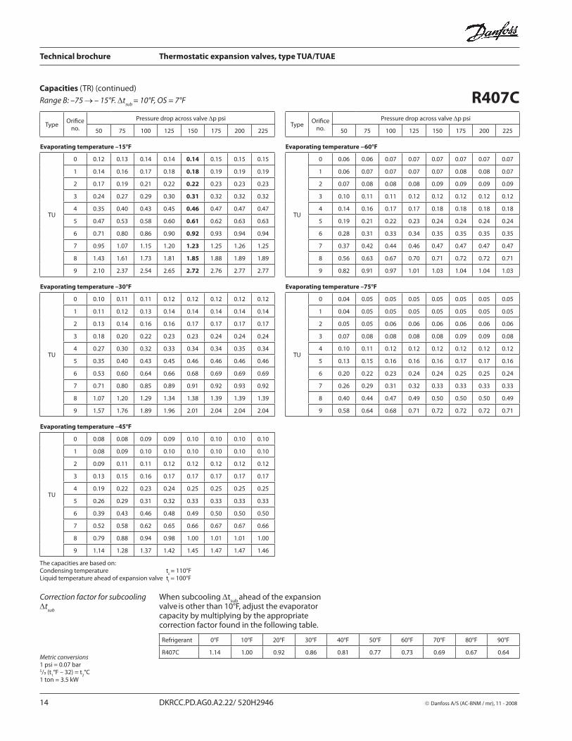
Capacities (TR) (continued)
R407C
Correction factor for subcooling Δt
sub
Refrigerant 0°F 10°F 20°F 30°F 40°F 50°F 60°F 70°F 80°F 90°F
R407C 1.14 1.00 0.92 0.86 0.81 0.77 0.73 0.69 0.67 0.64
When subcooling Δtsub ahead of the expansion
valve is other than 10°F, adjust the evaporator
capacity by multiplying by the appropriate correction factor found in the following table.
Metric conversions1 psi = 0.07 bar5/9 (t
1°F – 32) = t
2°C
1 ton = 3.5 kW
The capacities are based on:Condensing temperature t
c = 110°F
Liquid temperature ahead of expansion valve tl = 100°F
Range N: –40 → +50°F. Δtsub
= 10°F, OS = 7°F
Technical brochure Thermostatic expansion valves, type TUA/TUAE
14 DKRCC.PD.AG0.A2.22/ 520H2946 © Danfoss A/S (AC-BNM / mr), 11 - 2008
TypeOrifi ce
no.
Pressure drop across valve Δp psiType
Orifi ce no.
Pressure drop across valve Δp psi
50 75 100 125 150 175 200 225 50 75 100 125 150 175 200 225
Evaporating temperature –15°F Evaporating temperature −60°F
TU
0 0.12 0.13 0.14 0.14 0.14 0.15 0.15 0.15
TU
0 0.06 0.06 0.07 0.07 0.07 0.07 0.07 0.07
1 0.14 0.16 0.17 0.18 0.18 0.19 0.19 0.19 1 0.06 0.07 0.07 0.07 0.07 0.08 0.08 0.07
2 0.17 0.19 0.21 0.22 0.22 0.23 0.23 0.23 2 0.07 0.08 0.08 0.08 0.09 0.09 0.09 0.09
3 0.24 0.27 0.29 0.30 0.31 0.32 0.32 0.32 3 0.10 0.11 0.11 0.12 0.12 0.12 0.12 0.12
4 0.35 0.40 0.43 0.45 0.46 0.47 0.47 0.47 4 0.14 0.16 0.17 0.17 0.18 0.18 0.18 0.18
5 0.47 0.53 0.58 0.60 0.61 0.62 0.63 0.63 5 0.19 0.21 0.22 0.23 0.24 0.24 0.24 0.24
6 0.71 0.80 0.86 0.90 0.92 0.93 0.94 0.94 6 0.28 0.31 0.33 0.34 0.35 0.35 0.35 0.35
7 0.95 1.07 1.15 1.20 1.23 1.25 1.26 1.25 7 0.37 0.42 0.44 0.46 0.47 0.47 0.47 0.47
8 1.43 1.61 1.73 1.81 1.85 1.88 1.89 1.89 8 0.56 0.63 0.67 0.70 0.71 0.72 0.72 0.71
9 2.10 2.37 2.54 2.65 2.72 2.76 2.77 2.77 9 0.82 0.91 0.97 1.01 1.03 1.04 1.04 1.03
Evaporating temperature –30°F Evaporating temperature –75°F
TU
0 0.10 0.11 0.11 0.12 0.12 0.12 0.12 0.12
TU
0 0.04 0.05 0.05 0.05 0.05 0.05 0.05 0.05
1 0.11 0.12 0.13 0.14 0.14 0.14 0.14 0.14 1 0.04 0.05 0.05 0.05 0.05 0.05 0.05 0.05
2 0.13 0.14 0.16 0.16 0.17 0.17 0.17 0.17 2 0.05 0.05 0.06 0.06 0.06 0.06 0.06 0.06
3 0.18 0.20 0.22 0.23 0.23 0.24 0.24 0.24 3 0.07 0.08 0.08 0.08 0.08 0.09 0.09 0.08
4 0.27 0.30 0.32 0.33 0.34 0.34 0.35 0.34 4 0.10 0.11 0.12 0.12 0.12 0.12 0.12 0.12
5 0.35 0.40 0.43 0.45 0.46 0.46 0.46 0.46 5 0.13 0.15 0.16 0.16 0.16 0.17 0.17 0.16
6 0.53 0.60 0.64 0.66 0.68 0.69 0.69 0.69 6 0.20 0.22 0.23 0.24 0.24 0.25 0.25 0.24
7 0.71 0.80 0.85 0.89 0.91 0.92 0.93 0.92 7 0.26 0.29 0.31 0.32 0.33 0.33 0.33 0.33
8 1.07 1.20 1.29 1.34 1.38 1.39 1.39 1.39 8 0.40 0.44 0.47 0.49 0.50 0.50 0.50 0.49
9 1.57 1.76 1.89 1.96 2.01 2.04 2.04 2.04 9 0.58 0.64 0.68 0.71 0.72 0.72 0.72 0.71
Evaporating temperature –45°F
TU
0 0.08 0.08 0.09 0.09 0.10 0.10 0.10 0.10
1 0.08 0.09 0.10 0.10 0.10 0.10 0.10 0.10
2 0.09 0.11 0.11 0.12 0.12 0.12 0.12 0.12
3 0.13 0.15 0.16 0.17 0.17 0.17 0.17 0.17
4 0.19 0.22 0.23 0.24 0.25 0.25 0.25 0.25
5 0.26 0.29 0.31 0.32 0.33 0.33 0.33 0.33
6 0.39 0.43 0.46 0.48 0.49 0.50 0.50 0.50
7 0.52 0.58 0.62 0.65 0.66 0.67 0.67 0.66
8 0.79 0.88 0.94 0.98 1.00 1.01 1.01 1.00
9 1.14 1.28 1.37 1.42 1.45 1.47 1.47 1.46
R407CCapacities (TR) (continued)
Correction factor for subcooling Δt
sub
Refrigerant 0°F 10°F 20°F 30°F 40°F 50°F 60°F 70°F 80°F 90°F
R407C 1.14 1.00 0.92 0.86 0.81 0.77 0.73 0.69 0.67 0.64
When subcooling Δtsub
ahead of the expansion valve
is other than 10°F, adjust the evaporator
capacity by multiplying by the appropriate correction factor found in the following table.
Metric conversions1 psi = 0.07 bar5/9 (t
1°F – 32) = t
2°C
1 ton = 3.5 kW
The capacities are based on:Condensing temperature t
c = 110°F
Liquid temperature ahead of expansion valve tl = 100°F
Range B: –75 → – 15°F. Δtsub
= 10°F, OS = 7°F

Technical brochure Thermostatic expansion valves, type TUA/TUAE
© Danfoss A/S (AC-BNM / mr), 11 - 2008 DKRCC.PD.AG0.A2.22/ 520H2946 15
TypeOrifi ce
no.
Pressure drop across valve Δp psiType
Orifi ce no.
Pressure drop across valve Δp psi
75 100 125 150 175 200 225 250 75 100 125 150 175 200 225 250
Evaporating temperature +50°F Evaporating temperature 0°F
TU
0 0.12 0.13 0.14 0.14 0.14 0.14 0.14 0.14
TU
0 0.10 0.11 0.11 0.11 0.11 0.11 0.11 0.11
1 0.18 0.20 0.20 0.21 0.21 0.21 0.21 0.20 1 0.13 0.14 0.14 0.15 0.15 0.15 0.15 0.15
2 0.26 0.28 0.30 0.31 0.31 0.31 0.31 0.31 2 0.16 0.17 0.18 0.18 0.18 0.18 0.18 0.18
3 0.36 0.39 0.41 0.42 0.43 0.43 0.43 0.42 3 0.22 0.24 0.25 0.25 0.26 0.26 0.25 0.25
4 0.54 0.59 0.62 0.64 0.65 0.65 0.64 0.64 4 0.33 0.35 0.37 0.37 0.38 0.38 0.38 0.37
5 0.72 0.78 0.82 0.85 0.86 0.87 0.86 0.85 5 0.44 0.47 0.49 0.50 0.50 0.51 0.50 0.49
6 1.08 1.18 1.24 1.28 1.30 1.31 1.31 1.29 6 0.66 0.70 0.73 0.75 0.76 0.76 0.75 0.74
7 1.44 1.57 1.65 1.70 1.73 1.74 1.73 1.71 7 0.88 0.94 0.98 1.00 1.01 1.01 1.01 0.99
8 2.16 2.34 2.47 2.53 2.58 2.60 2.58 2.55 8 1.32 1.42 1.47 1.51 1.52 1.52 1.51 1.49
9 3.23 3.51 3.70 3.81 3.87 3.89 3.90 3.81 9 1.95 2.09 2.18 2.22 2.25 2.25 2.23 2.20
Evaporating temperature +40°F Evaporating temperature −20°F
TU
0 0.12 0.13 0.13 0.14 0.14 0.14 0.14 0.13
TU
0 0.09 0.09 0.09 0.10 0.10 0.10 0.09 0.09
1 0.17 0.19 0.19 0.20 0.20 0.20 0.20 0.19 1 0.10 0.11 0.11 0.12 0.12 0.12 0.11 0.11
2 0.24 0.26 0.27 0.28 0.29 0.29 0.29 0.28 2 0.12 0.13 0.13 0.14 0.14 0.14 0.14 0.13
3 0.33 0.36 0.38 0.39 0.40 0.40 0.39 0.39 3 0.17 0.18 0.19 0.19 0.19 0.19 0.19 0.19
4 0.50 0.54 0.57 0.59 0.60 0.60 0.59 0.59 4 0.25 0.27 0.28 0.28 0.28 0.28 0.28 0.28
5 0.66 0.72 0.76 0.78 0.79 0.79 0.79 0.78 5 0.34 0.36 0.37 0.38 0.38 0.38 0.38 0.37
6 1.00 1.08 1.14 1.17 1.19 1.20 1.19 1.18 6 0.50 0.54 0.55 0.56 0.57 0.57 0.56 0.55
7 1.33 1.44 1.52 1.56 1.59 1.60 1.59 1.57 7 0.67 0.72 0.74 0.76 0.76 0.76 0.75 0.74
8 1.99 2.16 2.27 2.34 2.37 2.38 2.38 2.34 8 1.02 1.08 1.12 1.14 1.15 1.15 1.13 1.11
9 2.99 3.23 3.39 3.50 3.54 3.56 3.54 3.49 9 1.50 1.59 1.65 1.67 1.68 1.68 1.66 1.63
Evaporating temperature +20°F Evaporating temperature −40°F
TU
0 0.11 0.12 0.12 0.13 0.13 0.13 0.13 0.12
TU
0 0.07 0.08 0.08 0.08 0.08 0.08 0.08 0.07
1 0.15 0.17 0.17 0.18 0.18 0.18 0.18 0.17 1 0.08 0.08 0.08 0.09 0.09 0.09 0.08 0.08
2 0.20 0.21 0.22 0.23 0.23 0.23 0.23 0.23 2 0.09 0.10 0.10 0.10 0.10 0.10 0.10 0.09
3 0.28 0.30 0.31 0.32 0.32 0.33 0.32 0.32 3 0.13 0.13 0.14 0.14 0.14 0.14 0.14 0.14
4 0.41 0.45 0.47 0.48 0.48 0.48 0.48 0.48 4 0.19 0.20 0.20 0.21 0.21 0.20 0.20 0.20
5 0.55 0.59 0.62 0.64 0.65 0.65 0.64 0.64 5 0.25 0.26 0.27 0.28 0.28 0.27 0.27 0.27
6 0.82 0.89 0.93 0.96 0.97 0.97 0.97 0.96 6 0.37 0.39 0.40 0.41 0.41 0.41 0.40 0.39
7 1.10 1.19 1.24 1.28 1.29 1.30 1.29 1.27 7 0.50 0.53 0.54 0.55 0.55 0.55 0.54 0.53
8 1.65 1.78 1.86 1.92 1.94 1.95 1.94 1.91 8 0.75 0.80 0.82 0.83 0.83 0.83 0.82 0.80
9 2.46 2.66 2.77 2.84 2.88 2.89 2.87 2.83 9 1.10 1.16 1.20 1.21 1.22 1.21 1.19 1.17
R507Capacities (TR) (continued)
Correction factor for subcooling Δt
sub
Refrigerant 0°F 10°F 20°F 30°F 40°F 50°F 60°F 70°F 80°F 90°F
R507 1.17 1.00 0.89 0.81 0.74 0.69 0.64 0.60 0.55 0.52
When subcooling Δtsub ahead of the expansion
valve is other than 10°F, adjust the evaporator
capacity by multiplying by the appropriate correction factor found in the following table.
Metric conversions1 psi = 0.07 bar5/9 (t
1°F – 32) = t
2°C
1 ton = 3.5 kW
The capacities are based on:Condensing temperature t
c = 110°F
Liquid temperature ahead of expansion valve tl = 100°F
Range N: –40 → +50°F. Δtsub
= 10°F, OS = 7°F

Technical brochure Thermostatic expansion valves, type TUA/TUAE
16 DKRCC.PD.AG0.A2.22/ 520H2946 © Danfoss A/S (AC-BNM / mr), 11 - 2008
TypeOrifi ce
no.
Pressure drop across valve Δp psiType
Orifi ce
no.
Pressure drop across valve Δp psi
50 75 100 125 150 175 200 225 50 75 100 125 150 175 200 225
Evaporating temperature –15°F Evaporating temperature −60°F
TU
0 0.10 0.11 0.12 0.12 0.12 0.12 0.12 0.12
TU
0 0.06 0.07 0.07 0.07 0.07 0.07 0.07 0.07
1 0.14 0.16 0.17 0.17 0.17 0.17 0.17 0.17 1 0.06 0.07 0.07 0.08 0.08 0.08 0.08 0.07
2 0.18 0.20 0.21 0.22 0.23 0.23 0.23 0.23 2 0.07 0.08 0.09 0.09 0.09 0.09 0.09 0.09
3 0.25 0.28 0.30 0.31 0.32 0.32 0.32 0.31 3 0.11 0.12 0.12 0.12 0.13 0.12 0.12 0.12
4 0.37 0.42 0.44 0.46 0.47 0.47 0.47 0.47 4 0.15 0.17 0.18 0.18 0.18 0.18 0.18 0.18
5 0.50 0.56 0.59 0.61 0.63 0.63 0.63 0.62 5 0.21 0.23 0.24 0.24 0.24 0.24 0.24 0.24
6 0.75 0.84 0.89 0.92 0.94 0.95 0.95 0.94 6 0.31 0.34 0.35 0.36 0.36 0.36 0.36 0.35
7 1.00 1.12 1.19 1.23 1.26 1.27 1.26 1.25 7 0.41 0.45 0.47 0.48 0.49 0.49 0.48 0.47
8 1.50 1.68 1.79 1.85 1.88 1.90 1.89 1.87 8 0.62 0.68 0.71 0.73 0.74 0.74 0.73 0.72
9 2.23 2.49 2.65 2.74 2.79 2.81 2.80 2.77 9 0.91 0.99 1.04 1.06 1.07 1.07 1.06 1.04
Evaporating temperature –30°F Evaporating temperature –75°F
TU
0 0.09 0.10 0.10 0.10 0.11 0.11 0.11 0.10
TU
0 0.04 0.05 0.05 0.05 0.05 0.05 0.05 0.05
1 0.11 0.13 0.13 0.14 0.14 0.14 0.14 0.14 1 0.05 0.05 0.05 0.05 0.05 0.05 0.05 0.05
2 0.14 0.15 0.16 0.17 0.17 0.17 0.17 0.17 2 0.05 0.06 0.06 0.06 0.06 0.06 0.06 0.06
3 0.19 0.22 0.23 0.24 0.24 0.24 0.24 0.24 3 0.07 0.08 0.09 0.09 0.09 0.09 0.09 0.08
4 0.29 0.32 0.34 0.35 0.35 0.35 0.35 0.35 4 0.11 0.12 0.12 0.13 0.13 0.13 0.12 0.12
5 0.38 0.43 0.45 0.46 0.47 0.47 0.47 0.46 5 0.15 0.16 0.17 0.17 0.17 0.17 0.17 0.16
6 0.57 0.64 0.67 0.69 0.71 0.71 0.71 0.70 6 0.22 0.24 0.25 0.25 0.25 0.25 0.25 0.24
7 0.76 0.85 0.90 0.93 0.94 0.95 0.94 0.93 7 0.29 0.32 0.33 0.34 0.34 0.34 0.33 0.33
8 1.15 1.28 1.35 1.40 1.42 1.43 1.42 1.40 8 0.44 0.48 0.50 0.51 0.51 0.51 0.50 0.49
9 1.70 1.89 1.99 2.06 2.09 2.10 2.08 2.06 9 0.64 0.70 0.73 0.74 0.74 0.74 0.73 0.71
Evaporating temperature –45°F
TU
0 0.08 0.08 0.09 0.09 0.09 0.09 0.09 0.09
1 0.09 0.10 0.10 0.10 0.11 0.11 0.10 0.10
2 0.10 0.11 0.12 0.12 0.12 0.12 0.12 0.12
3 0.14 0.16 0.17 0.17 0.18 0.18 0.17 0.17
4 0.21 0.23 0.25 0.25 0.26 0.26 0.25 0.25
5 0.28 0.31 0.33 0.34 0.34 0.34 0.34 0.34
6 0.42 0.47 0.49 0.51 0.51 0.51 0.51 0.50
7 0.57 0.63 0.66 0.68 0.69 0.69 0.68 0.67
8 0.86 0.95 1.00 1.03 1.04 1.04 1.03 1.01
9 1.26 1.39 1.46 1.50 1.52 1.52 1.51 1.48
R507Capacities (TR) (continued)
Correction factor for subcooling Δt
sub
Refrigerant 0°F 10°F 20°F 30°F 40°F 50°F 60°F 70°F 80°F 90°F
R507 1.17 1.00 0.89 0.81 0.74 0.69 0.64 0.60 0.55 0.52
When subcooling Δtsub
ahead of the expansion valve
is other than 10°F, adjust the evaporator
capacity by multiplying by the appropriate correction factor found in the following table.
The capacities are based on:Condensing temperature t
c = 110°F
Liquid temperature ahead of expansion valve tl = 100°F
Range B: –75 → – 15°F. Δtsub
= 10°F, OS = 7°F

Technical brochure Thermostatic expansion valves, type TUA/TUAE
© Danfoss A/S (AC-BNM / mr), 11 - 2008 DKRCC.PD.AG0.A2.22/ 520H2946 17
Metric conversions1 psi = 0.07 bar5/9 (t
1°F – 32) = t
2°C
1 ton = 3.5 kW
Capacities (TR)(continued)Range N: –40 to +50°F. Δt
sub = 10°F, OS = 7°F
Refrigerant 0°F 10°F 20°F 30°F 40°F 50°F 60°F 70°F 80°F 90°F
R410A 1.14 1.00 0.89 0.83 0.77 0.72 0.68 0.65 0.61 0.59
Correction factorfor subcooling Δt
sub
When subcooling Δtsub
ahead of the expansion valve
is other than 10°F, adjust the evaporator
capacity by multiplying by the appropriate correction factor found in the following table.
R410A
TypeOrifi ce
no.
Pressure drop across valve ∆p psiType
Orifi ce
no.
Pressure drop across valve ∆p psi
50 100 150 200 250 300 350 400 50 100 150 200 250 300 350 400
Evaporating temperature +50°F Evaporating temperature 0°F
TU
0 0.17 0.22 0.24 0.26 0.26 0.26 0.25 0.24
TU
0 0.16 0.20 0.22 0.23 0.24 0.24 0.23 0.23
1 0.28 0.36 0.39 0.41 0.42 0.41 0.40 0.39 1 0.23 0.29 0.32 0.33 0.34 0.34 0.34 0.33
2 0.47 0.61 0.69 0.73 0.75 0.75 0.74 0.72 2 0.30 0.39 0.44 0.46 0.49 0.49 0.49 0.47
3 0.64 0.83 0.94 0.99 1.02 1.02 1.01 0.98 3 0.42 0.54 0.61 0.64 0.68 0.68 0.68 0.66
4 1.00 1.29 1.46 1.55 1.58 1.59 1.56 1.48 4 0.64 0.81 0.91 0.96 1.01 1.02 1.01 0.98
5 1.31 1.71 1.91 2.04 2.10 2.10 2.07 2.00 5 0.85 1.09 1.21 1.28 1.35 1.36 1.34 1.31
6 2.00 2.60 2.94 3.13 3.21 3.22 3.20 3.07 6 1.27 1.63 1.82 1.93 2.04 2.06 2.03 1.98
7 2.64 3.44 3.87 4.12 4.24 4.25 4.18 4.05 7 1.69 2.17 2.43 2.57 2.72 2.74 2.71 2.64
8 3.88 5.05 5.69 6.05 6.22 6.24 6.14 5.92 8 2.53 3.25 3.63 3.84 4.06 4.08 4.04 3.94
9 5.90 7.62 8.60 9.13 9.37 9.23 9.23 8.91 9 3.79 4.85 5.41 5.73 6.05 6.08 6.02 5.85
Evaporating temperature +40°F Evaporating temperature −20°F
TU
0 0.18 0.22 0.24 0.26 0.26 0.26 0.26 0.25
TU
0 0.14 0.18 0.19 0.20 0.21 0.21 0.21 0.20
1 0.28 0.35 0.38 0.40 0.41 0.41 0.40 0.39 1 0.19 0.24 0.26 0.28 0.29 0.29 0.28 0.27
2 0.44 0.58 0.65 0.69 0.73 0.73 0.72 0.70 2 0.23 0.30 0.33 0.35 0.37 0.37 0.36 0.36
3 0.61 0.78 0.88 0.94 0.99 0.99 0.98 0.95 3 0.32 0.41 0.46 0.49 0.51 0.51 0.51 0.50
4 0.94 1.22 1.37 1.45 1.52 1.53 1.51 1.46 4 0.48 0.61 0.68 0.72 0.76 0.76 0.75 0.74
5 1.24 1.61 1.81 1.92 2.02 2.03 2.00 1.94 5 0.65 0.82 0.91 0.96 1.02 1.02 1.01 0.98
6 1.88 2.45 2.75 2.93 3.09 3.10 3.06 2.97 6 0.96 1.22 1.37 1.44 1.53 1.53 1.52 1.48
7 2.49 3.23 3.64 3.87 4.07 4.09 4.04 3.92 7 1.29 1.64 1.83 1.93 2.04 2.05 2.03 1.98
8 3.68 4.77 5.37 5.71 6.01 6.03 5.95 5.76 8 1.94 2.46 2.74 2.90 3.06 3.07 3.04 2.96
9 5.58 7.24 8.11 8.60 9.04 9.07 8.93 8.65 9 2.87 3.65 4.06 4.28 4.52 4.54 4.49 4.37
Evaporating temperature +20°F Evaporating temperature −40°F
TU
0 0.17 0.21 0.24 0.25 0.25 0.25 0.25 0.24
TU
0 0.12 0.15 0.16 0.17 0.18 0.18 0.17 0.17
1 0.26 0.33 0.36 0.37 0.39 0.39 0.38 0.37 1 0.14 0.18 0.20 0.21 0.22 0.22 0.22 0.21
2 0.38 0.49 0.55 0.58 0.61 0.62 0.61 0.59 2 0.17 0.21 0.24 0.25 0.26 0.26 0.26 0.25
3 0.52 0.67 0.75 0.80 0.84 0.85 0.85 0.82 3 0.24 0.30 0.33 0.35 0.37 0.37 0.37 0.36
4 0.79 1.02 1.15 1.22 1.28 1.29 1.27 1.24 4 0.35 0.44 0.49 0.51 0.54 0.54 0.54 0.52
5 1.05 1.36 1.52 1.62 1.70 1.71 1.69 1.65 5 0.47 0.59 0.65 0.69 0.73 0.73 0.72 0.70
6 1.59 2.05 2.30 2.45 2.59 2.60 2.58 2.51 6 0.70 0.88 0.98 1.03 1.09 1.09 1.08 1.05
7 2.11 2.72 3.06 3.25 3.43 3.45 3.42 3.33 7 0.93 1.18 1.31 1.38 1.45 1.46 1.44 1.40
8 3.14 4.04 4.55 4.83 5.10 5.12 5.07 4.93 8 1.41 1.78 1.97 2.08 2.19 2.20 2.17 2.11
9 4.73 6.09 6.83 7.23 7.63 7.67 7.57 7.37 9 2.07 2.61 2.90 3.05 3.21 3.22 3.18 3.10
Technical brochure Thermostatic expansion valves, type TUA/TUAE
18 DKRCC.PD.AG0.A2.22/ 520H2946 © Danfoss A/S (AC-BNM / mr), 11 - 2008
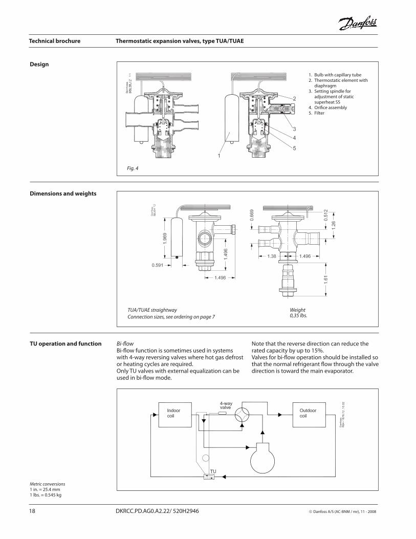
TUA/TUAE straightway
Connection sizes, see ordering on page 7
Weight0,35 lbs.
Dimensions and weights
Design
1. Bulb with capillary tube2. Thermostatic element with
diaphragm3. Setting spindle for
adjustment of static superheat SS
4. Orifi ce assembly5. Filter
Fig. 4
Metric conversions1 in. = 25.4 mm1 lbs. = 0.545 kg
TU operation and function Bi-fl owBi-fl ow function is sometimes used in systems with 4-way reversing valves where hot gas defrost or heating cycles are required.Only TU valves with external equalization can be used in bi-fl ow mode.
Note that the reverse direction can reduce the rated capacity by up to 15%.Valves for bi-fl ow operation should be installed so that the normal refrigerant fl ow through the valve direction is toward the main evaporator.
�������
��
����
�� �� ��
Technical brochure Thermostatic expansion valves, type TUA/TUAE
© Danfoss A/S (AC-BNM / mr), 11 - 2008 DKRCC.PD.AG0.A2.22/ 520H2946 19
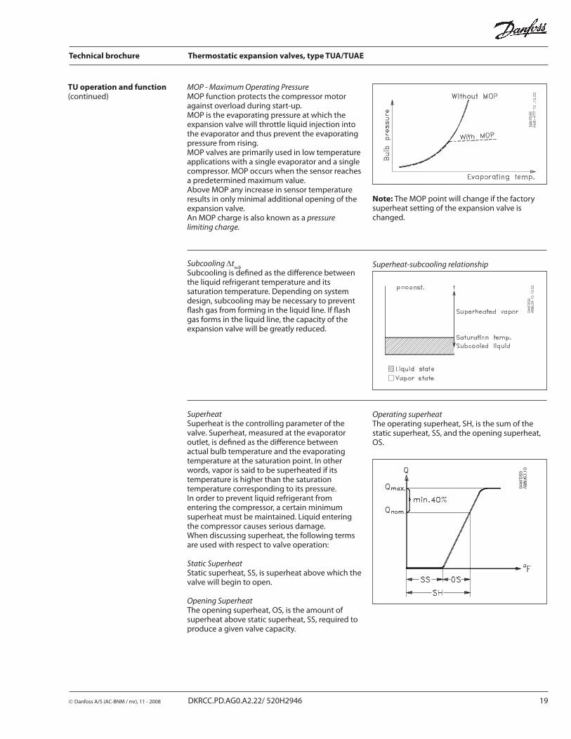
TU operation and function(continued)
Subcooling Δtsub
Subcooling is defi ned as the diff erence between the liquid refrigerant temperature and its saturation temperature. Depending on system design, subcooling may be necessary to prevent fl ash gas from forming in the liquid line. If fl ash gas forms in the liquid line, the capacity of the expansion valve will be greatly reduced.
Superheat-subcooling relationship
SuperheatSuperheat is the controlling parameter of the valve. Superheat, measured at the evaporator outlet, is defi ned as the diff erence between actual bulb temperature and the evaporating temperature at the saturation point. In other words, vapor is said to be superheated if its temperature is higher than the saturation temperature corresponding to its pressure.In order to prevent liquid refrigerant from entering the compressor, a certain minimum superheat must be maintained. Liquid en ter ing the compressor causes serious damage.When discussing superheat, the following terms are used with respect to valve operation:
Static SuperheatStatic superheat, SS, is superheat above which the valve will begin to open.
Opening SuperheatThe opening superheat, OS, is the amount of superheat above static superheat, SS, required to produce a given valve capacity.
Operating superheatThe operating superheat, SH, is the sum of the static superheat, SS, and the opening superheat, OS.
MOP - Maximum Operating PressureMOP function protects the compressor motor against overload during start-up.MOP is the evaporating pressure at which the expansion valve will throttle liquid injection into the evaporator and thus prevent the evap o rat ing pressure from rising.MOP valves are primarily used in low temperature applications with a single evap o ra tor and a single compressor. MOP occurs when the sensor reaches a predetermined maximum value.Above MOP any increase in sensor temperature results in only minimal additional opening of the expansion valve.An MOP charge is also known as a pressure limiting charge.
Note: The MOP point will change if the factory superheat setting of the expansion valve is changed.
Technical brochure Thermostatic expansion valves, type TUA/TUAE
20 DKRCC.PD.AG0.A2.22/ 520H2946 © Danfoss A/S (AC-BNM / mr), 11 - 2008