thermostatic expansion valves - iglotech krakó · 18 castel thermostatic expansion valves series...
TRANSCRIPT
17
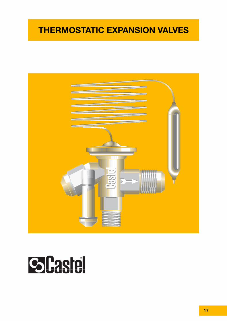
THERMOSTATIC EXPANSION VALVES

18
Castel thermostatic expansion valves series22 regulate the flow of refrigerant liquid intoevaporators; the liquid injection is controlledby the refrigerant superheat.The new Castel “22” series are designed towork with interchangeable orifice assembly,to provide flexibility in selection of capacities,and can be used in a wide range ofapplications as listed below:• Refrigeration systems (display cases in
supermarkets, freezers, ice cream and icemaker machines, transport refrigerationetc).
• Air conditioning systems• Heat pump systems• Liquid chillerswhich use refrigerant fluids proper to theGroup II (as defined in Article 9, Section2.2, of Directive 97/23/EC and referred to inDirective 67/548/EEC).
Castel thermostatic expansion valves actsas throttle device between the high pressureand the low pressure sides of refrigerationsystems and ensure that the rate ofrefrigerant flow into the evaporator exactlymatches the rate of evaporation of liquidrefrigerant in the evaporator. If the actualsuperheat is higher than the set point thevalve feeds the evaporator with more liquidrefrigerant, if the actual superheat is lowerthan the set point the valve decreases theflow of liquid refrigerant to the evaporator.Thus the evaporator is fully utilized and noliquid refrigerant may reach the compressor.
Castel thermostatic expansion valve series22 is made up of two parts that must worktogether: the first is the body, which is theactuator of the regulator, and the second isthe orifice, which contains the valve andattends the expansion of the refrigeratingfluid.
Body assembly: two parts make it up: thethermostatic (power) element and the bodywith its inner elements.The thermostatic element is the motor of thevalve; a sensing bulb is connected to thediaphragm assembly by 1.5 meter length ofcapillary tubing, which transmits bulb
CONSTRUCTION
OPERATION
APPLICATION
THERMOSTATIC EXPANSION VALVES SERIES 22WITH INTERCHANGEABLE ORIFICE ASSEMBLY
www.castel.it
pressure to the top of the valve’sdiaphragm. The sensing bulb pressure is afunction of the temperature of thethermostatic charge that is the substancewithin the bulb.The body is made from forged brass withconnection in angle configuration. Theinterchangeable orifice assembly can bereplaced through the inlet connection. Asteel rod, inside the body, transfers thediaphragm movement to the plug inside theorifice assembly. When the thermostaticcharge pressure increases, the diaphragmwill be deflected downward transferring thismotion to the plug, which lifts from seat andallows the liquid passing through orifice. Aspring opposes the force underneath thediaphragm and the side spindle can adjustits tension. Static superheat increases byturning the side spindle clockwise anddecreased by turning the spindle counterclockwise.The thermostatic element is hardlyconnected by brazing to the forged brassbody to avoid any leakage.The body assembly can be supplied withinternal or external equalizer; both typescan also be supplied either with flareconnections or with solder connections(outlet and external equalizer if present).

19
TH
ER
MO
STA
TIC
EX
PAN
SIO
N VA
LVE
S
www.castel.it
Table 1: General Caracteristics of Body Assemblies of Thermostatic Expansion Valves
externalequalizer
internalequalizer
Catalogue number
IN OUT Equal. OUT OUT Equal. min max
PS [bar]
SAE Flare ODS [mm] ODS [in]
Refri
gera
nt
Evap
orat
ing
Tem
pera
ture
Ran
ge[°C
]
Max
bul
b te
mpe
ratu
re [
°C]
MOP
TS [°C]Connections
–
2210/4E
2210/M12SE
2210/4SE
–
2211/4E
2211/M12SE
2211/4SE
–
2220/4E
2220/M12SE
2220/4SE
–
2221/4E
2221/M12SE
2221/4SE
–
2230/4E
2230/M12SE
2230/4SE
–
2231/4E
2231/M12SE
2231/4SE
–
2234/4E
2234/M12SE
2234/4SE
2210/4
2210/M12S
2210/4S
–
2211/4
2211/M12S
2211/4S
–
2220/4
2220/M12S
2220/4S
–
2221/4
2221/M12S
2221/4S
–
2230/4
2230/M12S
2230/4S
–
2231/4
2231/M12S
2231/4S
–
2234/4
2234/M12S
2234/4S
–
3/8"
3/8"
3/8"
1/2"
–
–
1/2"
–
–
1/2"
–
–
1/2"
–
–
1/2"
–
–
1/2"
–
–
1/2"
–
–
1/2"
–
–
1/2"
–
–
1/2"
–
–
1/2"
–
–
1/2"
–
–
1/2"
–
–
1/2"
–
–
–
–
–
1/4"
–
–
–
–
–
1/4"
–
–
–
–
–
1/4"
–
–
–
–
–
1/4"
–
–
–
–
–
1/4"
–
–
–
–
–
1/4"
–
–
–
–
–
1/4"
–
–
–
12
–
–
12
–
–
12
–
–
12
–
–
12
–
–
12
–
–
12
–
–
12
–
–
12
–
–
12
–
–
12
–
–
12
–
–
12
–
–
12
–
Equal.
–
–
–
–
6
–
–
–
–
–
6
–
–
–
–
–
6
–
–
–
–
–
6
–
–
–
–
–
6
–
–
–
–
–
6
–
–
–
–
–
6
–
–
–
1/2"
–
–
1/2"
–
–
1/2"
–
–
1/2"
–
–
1/2"
–
–
1/2"
–
–
1/2"
–
–
1/2"
–
–
1/2"
–
–
1/2"
–
–
1/2"
–
–
1/2"
–
–
1/2"
–
–
1/2"
–
–
–
–
–
1/4"
–
–
–
–
–
1/4"
–
–
–
–
–
1/4"
–
–
–
–
–
1/4"
–
–
–
–
–
1/4"
–
–
–
–
–
1/4"
–
–
–
–
–
1/4"
R22
R407C
R134a
R404A
R507
- 40 ➝
+ 10
- 40 ➝
+ 10
- 40 ➝
+ 10
- 60 ➝
- 25
without
+ 15 °C
(95 psi)
without
+ 15 °C
(55 psi)
without
+ 15 °C
(120 psi)
- 20 °C
(30 psi)
100
(1)-60 +120 34
RiskCategoryaccording
to PED
Art. 3.3
(1) when valve is installed. 60 °C with element not mounted

20 www.castel.it
Liquid charge: the behaviour of valves withliquid charge is exclusively determined bytemperature changes at the bulb and notsubject to any cross-ambient interference.They feature a fast response time and thusreact quickly in the control circuit. Castelthermostatic expansion valves with liquidcharge cannot incorporate MOP functions.Gas charge: the behaviour of valves withgas charge will be determined by the lowesttemperature at any part of the expansionvalve (thermostatic element, capillary tubeor bulb). If any parts other than the bulb aresubjected to the lowest temperature,malfunction of expansion valve may occur(charge migration). Castel thermostaticexpansion valves with gas charge alwaysfeature MOP functions and include ballastedbulb. Ballast in the bulb has a dampingeffect on the valve regulation and leads toslow opening and fast closure of the valve.
MOP (Maximum Operating Pressure): thisfunctionality limits the evaporator pressureto a maximum value to protect thecompressor from the overload condition(Motor Overload Protection). MOP is theevaporating pressure at which theexpansion valve will throttle liquid injectioninto the evaporator and thus prevent theevaporating pressure from rising. Expansionvalve operates as superheat control innormal working range and operates aspressure regulator within MOP range. TheMOP point will change if the factorysuperheat setting of the expansion valve ischanged. Superheat adjustments influencethe MOP point as following:• increase of superheat
decrease of MOP• decrease of superheat
increase of MOP
THERMOSTATIC CHARGESThe nuts for flare connection type and theinlet-brazing adapter for solder connectiontype can be ordered separately.
The main part of body assembly are madewith the following materials:• stainless steel for bulb, capillary tubing,
diaphragm casing, diaphragm and rod• hot forged brass EN 12420 – CW 617N
for body• brass EN 12164 – CW 614N for
superheat setting spindle and springholder
• steel DIN 17223-1 for spring• copper tube EN 12735-1 – Cu DHP for
solder connection
Orifice assembly: interchangeable orificeassembly provide a wide range of capacityfrom 0,5 up to 15,5 kW (nominal capacitywith R22). The external cartridge containsthe following elements: housing, plug(metering device), seat, spring and strainer.The rigid design of orifice assembly and itsinternal components make sure that plugand seat will withstand all types of criticaloperations (liquid hammering, cavitation,sudden variation of pressure andtemperature contaminants). The spring holdsthe plug firmly to the seat to ensure theminimum leakage through the valve; forpositive shut-off, the installation of asolenoid valve is required. Orifice assembliesare available in these two solutions:• with conical flanged strainer, for valves
with SAE Flare threaded connections.• with flat flanged strainer, for valves with
ODS solder connections, to use withadapter series 2271.
Orifice assemblies strainers can be cleanedor exchanged, in this last case it’s possibleto order separately the following two typesof strainers.• strainer 2290 for valves with SAE Flare
threaded connections.• strainer 2290/S for valves with ODS
solder connections.
21
• Operating superheat: it’s the sum of staticand opening superheat
Subcooling: it’s defined as the differencebetween the liquid refrigerant temperatureand its saturation temperature. Subcoolinggenerally increases the capacity ofrefrigeration system and may be accountedfor when dimensioning an expansion valve.Depending on system design, subcoolingmay be necessary to prevent flash gas fromforming in the liquid line. If flash gas formsin the liquid line, the capacity of expansionvalve will be greatly reduced. All capacitytables, in this chapter, are calculated for asubcooling value of 4 °C; if the actualsubcooling is higher than 4 °C theevaporator capacity must be divided by theappropriate correction factor shown is thetables below every capacity tables.
Superheat: this is the controlling parameterof the expansion valve. Superheat,measured at the evaporator outlet, isdefined as the difference between actualbulb temperature and the evaporatingtemperature at the saturation point. In orderto prevent liquid refrigerant from enteringthe compressor, a certain minimumsuperheat must be maintained. In expansionvalve operation the following terms areused:• Static superheat: it’s the superheat above
that the valve will begin to open. Castelthermo expansion valves are factorypreset for optimum static superheatsetting. This setting should be modifiedonly if absolutely necessary. Staticsuperheat for Castel valves without MOPis 5 °C and for Castel valves with MOP is4°C.
• Opening superheat: it’s the amount ofsuperheat above the static superheatrequired to produce a given valvecapacity
www.castel.it
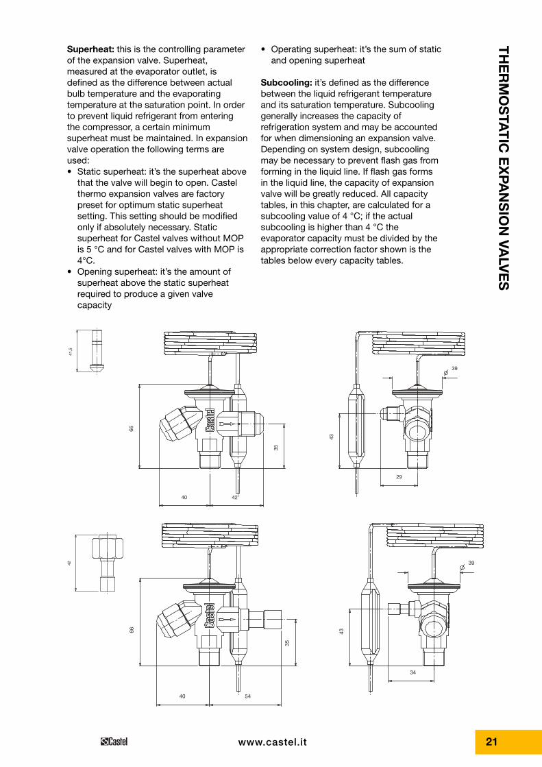
41,5
40
39
35
66
43
29
42
42
66
35
54
34
40
39
43
TH
ER
MO
STA
TIC
EX
PAN
SIO
N VA
LVE
S

22
Step 3Determine required orifice size. Use thepressure drop across the valve, theevaporating temperature and the calculatedevaporator capacity to select thecorresponding orifice size from the capacitytable corresponding to the chosenrefrigerant.
Step 4Select a thermostatic charge. Chose thetype of charge, liquid without MOP or gaswith MOP, and the temperature range,normal temperature or low temperature.
Step 5Determine if external equalizer is required.External equalizer is always required if adistributor is used or if there is anappreciable difference in pressure from thevalve outlet to the bulb location. Finallydetermine the type of connections and theirsizes.
To correctly select a thermo expansion valveon a refrigerating system, the followingdesign conditions must be available:Type of refrigerantEvaporator capacity, Qe
Evaporating temperature/pressure, Te / pe
Lowest possible condensing temperature/pressure, Tc / pc
Liquid refrigerant temperature, Tl
Pressure drop in the liquid line, distributorand evaporator, �p
The following procedure helps to select thecorrect valve for the system.
Step 1Determine the pressure drop across thevalve. The pressure drop is calculated bythe formula:
where:Pc = condensing pressurePe = evaporating pressure�p = sum of pressure drops in the liquidline, distributor and evaporator
Step 2Determine required valve capacity. Use theevaporating capacity Qe to select therequired valve size at a given evaporatingtemperature. If necessary, correct theevaporator capacity for subcooling.Subcooling liquid refrigerant entering theevaporator increase the evaporatorcapacity, so that a smaller valve may berequired.
The subcooling is calculated by the formula:
From the subcooling corrector factor tablefind the appropriate corrector factor Fsub
corresponding to the �Tsub calculated anddetermine the required valve capacity by theformula:
sub
esub F
QQ =∆
lcsub TTT −=∆
( )pppp ectot ∆+−=∆
SELECTION
www.castel.it

23
• Type of refrigerant R134a• Evaporator capacity, Qe 6 kW• Evaporating temperature/
pressure, Te - 10 °C• Lowest possible condensing
temperature/pressure, Tc + 30 °C• Liquid refrigerant temperature, Tl + 20 °C• Pressure drop in the liquid line, distributor
and evaporator, �p 1,5 bar
STEP 1 - Determine the pressure dropacross the valve• Condensing pressure at
+ 30 °C - pc = 6,71 bar• Evaporating pressure at
- 10 °C - pe = 1,01 bar
( ) bar2,45,101,171,6p tot ⋅=+−=∆
SIZING EXAMPLE
STEP 2 - Determine required valve capacity
From the subcooling corrector factor table5b, we find the appropriate corrector factorFsub equal to 1,08 for �Tsub = 10 °C. Requiredvalve capacity is:
STEP 3 - Determine required orifice sizeUsing the capacity table for R134a on page25 with:• pressure drop across the valve = 4,2 bar• evaporating temperature = - 10 °C• calculated evaporator capacity = 5,55 kW• select the corresponding orifice 2205
(N.B.: the expansion valve capacity mustbe equal or slightly more than thecalculated evaporator capacity)
Main valve data are indicated on the upperside of the thermostatic element and on thecartridge surface of the orifice assembly.On the thermostatic element you may findthe following data:• The valve code number• The refrigerant• The evaporating temperature range• The MOP value, if present• The maximum allowable pressure PS• The date of productionOn the cartridge of orifice assembly youmay find the following data:• The size of the orifice• The date of productionOn the plastic cap of the orifice assemblypackage the orifice size is marked. The capcan easily be fastened around the valvecapillary tube to clearly identify the valvesize.
MARKING
kW5,551,086Q sub ⋅==∆
C102030Tsub °⋅=−=∆
TH
ER
MO
STA
TIC
EX
PAN
SIO
N VA
LVE
S
www.castel.it
Rated capacities, for temperature range - 40 ➝ + 10, are based on:– Evaporating temperature Tevap = + 5 °C– Condensing temperature Tcond = + 32 °C– Refrigerant liquid temperature ahead
of valve Tliq = + 28 °C
Rated capacities, for temperature range - 60 ➝ - 25, are based on:– Evaporating temperature Tevap = - 30 °C– Condensing temperature Tcond = + 32 °C– Refrigerant liquid temperature ahead
of valve Tliq = + 28 °C
Table 3: Solder adapters
Catalogue NumberODS Connections
[in] [mm]
2271/M6S
2271/2S
2271/3S
2271/M10S
–
1/4"
3/8"
–
6
–
–
10
Table 2: Orifice Assemblies - Rated Capacities in kW
Valves with SAE Flareconnections
Catalogue Number
Valves with ODS
connections R22R407C R134a R404A
R507R404AR507
Evaporating Temperature Range [°C]
- 40 ➝ + 10 -60➝ -25
220X
2200
2201
2202
2203
2204
2205
2206
220X/S
2200/S
2201/S
2202/S
2203/S
2204/S
2205/S
2206/S
0,5
1,0
2,5
3,5
5,2
8,0
10,5
15,5
0,4
0,9
1,8
2,6
4,6
6,7
8,6
10,5
0,38
0,7
1,6
2,1
4,2
6,0
7,7
9,1
0,38
0,7
1,6
2,1
3,5
4,9
6,0
6,6

24 www.castel.it
Table 4a: Refrigerant R22/R407C - Capacities in kW for temperature range - 40°C ? +10°C
Orificecode
Orificecode
Pressure drop across valve [bar] Pressure drop across valve [bar]
2 4 6 8 10 12 14 16 2 4 6 8 10 12 14 16
Evaporating temperature = 0 °C
220X 0,37 0,48 0,55 0,59 0,63 0,65 0,66 0,66
2200 0,84 1,0 1,2 1,3 1,3 1,4 1,4 1,4
2201 1,9 2,4 2,7 3,0 3,1 3,2 3,3 3,3
2202 2,6 3,4 4,0 4,3 4,6 4,8 4,9 5,0
2203 4,6 6,1 7,1 7,8 8,2 8,5 8,7 8,8
2204 6,9 9,1 10,5 11,5 12,2 12,7 13,0 13,2
2205 8,8 11,6 13,3 14,6 15,5 16,1 16,4 16,6
2206 10,8 14,2 16,3 17,8 18,9 19,6 20,0 20,2
Evaporating temperature = -20 °C
220X 0,44 0,50 0,54 0,57 0,59 0,61 0,61
2200 0,88 1,0 1,1 1,1 1,2 1,2 1,2
2201 1,7 1,9 2,0 2,2 2,3 2,3 2,3
2202 2,4 2,7 2,9 3,1 3,2 3,3 3,3
2203 4,2 4,8 5,2 5,5 5,8 5,9 6,0
2204 6,2 7,1 7,7 8,2 8,5 8,7 8,8
2205 7,9 9,0 9,8 10,3 10,8 11,0 11,2
2206 9,6 11,0 11,9 12,6 13,1 13,5 13,7
Evaporating temperature = -40 °C
220X 0,42 0,45 0,48 0,50 0,52 0,53
2200 0,8 0,86 0,92 0,95 0,98 0,99
2201 1,3 1,4 1,4 1,5 1,5 1,6
2202 1,7 1,9 2,0 2,0 2,1 2,1
2203 3,1 3,4 3,5 3,7 3,8 3,8
2204 4,6 4,9 5,2 5,4 5,6 5,7
2205 5,8 6,3 6,6 6,9 7,1 7,2
2206 7,1 7,7 8,1 8,4 8,7 8,8
Evaporating temperature = +10 °C
220X 0,37 0,48 0,55 0,60 0,63 0,65 0,65 0,67
2200 0,87 1,1 1,2 1,3 1,4 1,4 1,4 1,5
2201 2,2 2,8 3,2 3,4 3,6 3,7 3,8 3,8
2202 3,0 4,0 4,7 5,1 5,4 5,6 5,8 5,8
2203 5,4 7,2 8,3 9,1 9,7 10,0 10,2 10,3
2204 8,1 10,8 12,5 13,8 14,5 15,0 15,5 15,5
2205 10,2 13,6 15,7 17,2 18,3 18,9 19,3 19,5
2206 12,6 16,7 19,3 21,0 22,3 23,1 23,5 23,7
Evaporating temperature = -10 °C
220X 0,37 0,47 0,53 0,57 0,60 0,63 0,64 0,64
2200 0,79 0,96 1,1 1,2 1,2 1,3 1,3 1,3
2201 1,6 2,0 2,3 2,5 2,6 2,7 2,8 2,8
2202 2,2 2,9 3,3 3,6 3,8 4,0 4,1 4,1
2203 3,9 5,1 5,9 6,4 6,8 7,1 7,3 7,3
2204 5,8 7,6 8,7 9,5 10,1 10,5 10,8 10,9
2205 7,4 9,6 11,0 12,0 12,8 13,3 13,6 13,8
2206 9,1 11,6 13,5 14,7 15,6 16,2 16,6 16,8
Evaporating temperature = -30 °C
220X 0,40 0,45 0,49 0,52 0,55 0,56 0,57
2200 0,79 0,9 0,96 1,0 1,1 1,1 1,1
2201 1,4 1,5 1,7 1,8 1,8 1,9 1,9
2202 1,9 2,2 2,7 2,5 2,6 2,6 2,7
2203 3,4 3,9 4,2 4,4 4,6 4,7 4,8
2204 5,0 5,7 6,2 6,6 6,8 7,0 7,1
2205 6,4 7,2 7,8 8,3 8,6 8,8 9,0
2206 7,8 8,8 9,6 10,1 10,5 10,8 11,0
Table 4b: Refrigerant R22/R407C - Correction factor for subcooling �tsub > 4°C
�tsub [°C] 4 10 15 20 25 30 35 40 45 50
Fsub 1,00 1,06 1,11 1,15 1,20 1,25 1,30 1,35 1,39 1,44
When subcooling ahead of the expansion valve is other than 4 °C, adjust the evaporatore capacity by dividing bythe appropriate correction factor found in Table 4b

25
TH
ER
MO
STA
TIC
EX
PAN
SIO
N VA
LVE
S
www.castel.it
Table 5a: Refrigerant R134a - Capacities in kW for temperature range - 40°C ➝➝ +10°C
Orificecode
Orificecode
Pressure drop across valve [bar] Pressure drop across valve [bar]
2 4 6 8 10 2 4 6 8 10
Evaporating temperature = 0 °C
220X 0,33 0,42 0,46 0,47 0,49
2200 0,65 0,78 0,86 0,89 0,91
2201 1,3 1,6 1,7 1,8 1,8
2202 1,7 2,2 2,4 2,6 2,6
2203 3,0 3,9 4,4 4,6 4,7
2204 4,5 5,7 6,4 6,8 7,0
2205 5,7 7,3 8,1 8,6 8,8
2206 7,0 8,9 1,0 10,5 10,8
Evaporating temperature = -20 °C
220X 0,28 0,35 0,39 0,41 0,42
2200 0,53 0,62 0,69 0,72 0,73
2201 0,81 1,0 1,1 1,2 1,2
2202 1,1 1,4 1,5 1,6 1,7
2203 2,0 2,5 2,8 2,9 3,0
2204 2,9 3,6 4,0 4,3 4,4
2205 3,7 4,6 5,1 5,4 5,5
2206 4,5 5,6 6,2 6,6 6,8
Evaporating temperature = -40 °C
220X 0,23 0,28 0,32 0,33 0,34
2200 0,44 0,50 0,54 0,56 0,57
2201 0,54 0,65 0,72 0,78 0,77
2202 0,7 0,9 1,0 1,0 1,0
2203 1,3 1,6 1,8 1,9 1,9
2204 1,9 2,3 2,6 2,7 2,7
2205 2,4 2,9 3,2 3,5 3,5
2206 3,0 3,6 4,0 4,2 4,3
Evaporating temperature = +10 °C
220X 0,34 0,43 0,47 0,50 0,51
2200 0,71 0,86 0,93 0,97 0,98
2201 1,5 1,9 2,1 2,2 2,2
2202 2,0 2,6 3,0 3,1 3,2
2203 3,6 4,7 5,3 5,6 5,8
2204 5,4 7,0 7,8 8,3 8,6
2205 6,9 8,9 9,9 10,8 10,9
2206 8,4 10,8 12,1 12,8 13,2
Evaporating temperature = -10 °C
220X 0,30 0,36 0,43 0,44 0,44
2200 0,59 0,70 0,77 0,81 0,82
2201 1,0 1,3 1,4 1,5 1,5
2202 1,4 1,8 2,0 2,1 2,1
2203 2,5 3,1 3,5 3,7 3,8
2204 3,6 4,6 5,1 5,4 5,6
2205 4,6 5,8 6,5 6,9 7,1
2206 5,7 7,1 8,0 8,4 8,6
Evaporating temperature = -30 °C
220X 0,25 0,32 0,35 0,37 0,38
2200 0,48 0,55 0,61 0,64 0,64
2201 0,66 0,80 0,88 0,93 0,95
2202 0,9 1,1 1,2 1,3 1,3
2203 1,6 2,0 2,2 2,3 2,3
2204 2,3 2,9 3,2 3,3 3,4
2205 3,0 3,6 4,0 4,2 4,3
2206 3,6 4,4 4,9 5,2 5,3
Table 5b: Refrigerant R134a - Correction factor for subcooling �tsub > 4°C
�tsub [°C] 4 10 15 20 25 30 35 40 45 50
Fsub 1,00 1,08 1,13 1,19 1,25 1,31 1,37 1,42 1,48 1,54
When subcooling ahead of the expansion valve is other than 4 °C, adjust the evaporatore capacity by dividing bythe appropriate correction factor found in Table 5b

26 www.castel.it
Table 6a: Refrigerant R404A/R507 - Capacities in kW for temperature range - 40°C ➝➝ +10°C
Orificecode
Orificecode
Pressure drop across valve [bar] Pressure drop across valve [bar]
2 4 6 8 10 12 14 16 2 4 6 8 10 12 14 16
Evaporating temperature = 0 °C
220X 0,30 0,37 0,41 0,42 0,43 0,43 0,43 0,41
2200 0,68 0,80 0,87 0,90 0,92 0,93 0,91 0,87
2201 1,53 1,86 2,04 2,13 2,18 2,18 2,15 2,08
2202 2,06 2,64 2,95 3,13 3,22 3,25 3,21 3,11
2203 3,68 4,72 5,27 5,59 5,75 5,80 5,73 5,55
2204 5,49 7,15 7,86 8,33 8,58 8,64 8,53 8,27
2205 6,97 8,92 9,95 10,52 10,83 10,90 10,76 10,43
2206 8,57 10,93 12,16 12,85 13,21 13,30 13,12 12,72
Evaporating temperature = -20 °C
220X 0,35 0,38 0,40 0,39 0,40 0,39 0,38
2200 0,70 0,75 0,77 0,79 0,79 0,79 0,76
2201 1,34 1,45 1,50 1,52 1,52 1,51 1,47
2202 1,85 2,04 2,14 2,17 2,18 2,16 2,09
2203 3,32 3,66 3,83 3,89 3,90 3,86 3,75
2204 4,88 5,40 5,64 5,75 5,77 5,71 5,56
2205 6,20 6,86 7,17 7,29 7,31 7,23 7,05
2206 7,60 8,39 8,75 8,91 8,93 8,84 8,61
Evaporating temperature = -40 °C
220X 0,32 0,33 0,33 0,33 0,32 0,32
2200 0,60 0,61 0,62 0,61 0,60 0,59
2201 0,92 0,96 0,97 0,96 0,94 0,91
2202 1,27 1,32 1,33 1,31 1,28 1,24
2203 2,28 2,36 2,38 2,36 2,31 2,24
2204 3,34 3,47 3,50 3,48 3,42 3,33
2205 4,25 4,41 4,45 4,43 4,36 4,24
2206 5,19 5,39 5,45 5,42 5,33 5,19
Evaporating temperature = +10 °C
220X 0,28 0,35 0,40 0,42 0,43 0,43 0,42 0,41
2200 0,67 0,82 0,90 0,94 0,96 0,96 0,93 0,90
2201 1,70 2,10 2,30 2,42 2,48 2,46 2,41 2,34
2202 2,32 3,00 3,39 3,61 3,73 3,74 3,68 3,59
2203 4,15 5,36 6,03 6,43 6,63 6,66 6,55 6,39
2204 6,24 8,06 9,06 9,66 9,95 9,98 9,81 9,57
2205 7,91 10,17 11,43 12,16 12,53 12,56 12,34 12,03
2206 9,71 12,47 13,98 14,86 15,29 15,31 15,05 14,66
Evaporating temperature = -10 °C
220X 0,30 0,37 0,40 0,42 0,42 0,42 0,41 0,41
2200 0,65 0,76 0,82 0,84 0,87 0,87 0,85 0,83
2201 1,31 1,61 1,74 1,81 1,84 1,85 1,84 1,78
2202 1,76 2,24 2,50 2,62 2,69 2,71 2,68 2,60
2203 3,14 4,02 4,47 4,69 4,81 4,84 4,79 4,65
2204 4,66 5,97 6,61 6,95 7,13 7,18 7,11 6,91
2205 5,93 7,57 8,39 8,81 9,02 9,08 8,99 8,73
2206 7,28 9,27 10,26 10,76 11,00 11,08 10,97 10,65
Evaporating temperature = -30 °C
220X 0,35 0,37 0,36 0,37 0,36 0,35
2200 0,67 0,70 0,70 0,70 0,69 0,67
2201 1,18 1,21 1,23 1,21 1,20 1,17
2202 1,63 1,69 1,71 1,70 1,68 1,64
2203 2,93 3,04 3,07 3,06 3,02 2,93
2204 4,28 4,47 4,52 4,51 4,46 4,35
2205 5,45 5,68 5,74 5,74 5,67 5,52
2206 6,66 6,94 7,02 7,01 6,93 6,75
Table 6b: Refrigerant R404A/R507 - Correction factor for subcooling �tsub > 4°C
�tsub [°C] 4 10 15 20 25 30 35 40 45 50
Fsub 1,00 1,10 1,20 1,29 1,37 1,46 1,54 1,63 1,70 1,78
When subcooling ahead of the expansion valve is other than 4 °C, adjust the evaporatore capacity by dividing bythe appropriate correction factor found in Table 6b

27
TH
ER
MO
STA
TIC
EX
PAN
SIO
N VA
LVE
S
www.castel.it
Table 7a: Refrigerant R404A/R507 - Capacities in kW for temperature range - 60°C ➝➝ - 25°C
Orificecode
Orificecode
Pressure drop across valve [bar] Pressure drop across valve [bar]
2 4 6 8 10 12 14 16 2 4 6 8 10 12 14 16
Evaporating temperature = -30 °C
2200 0,53 0,64 0,67 0,70 0,70 0,70 0,69 0,67
2201 0,88 1,07 1,18 1,21 1,23 1,21 1,20 1,17
2202 1,18 1,47 1,63 1,69 1,71 1,70 1,68 1,64
2203 2,12 2,65 2,93 3,04 3,07 3,05 3,02 2,93
2204 3,09 3,88 4,28 4,47 4,52 4,51 4,46 4,35
2205 3,94 4,94 5,45 5,68 5,74 5,74 5,67 5,52
2206 4,83 6,06 6,66 6,94 7,02 7,01 6,93 6,75
Evaporating temperature = -50 °C
2200 0,49 0,53 0,54 0,54 0,53 0,52 0,50
2201 0,51 0,57 0,60 0,60 0,60 0,60 0,59
2202 0,91 0,99 1,02 1,02 1,01 0,98 0,95
2203 1,63 1,73 1,84 1,84 1,81 1,78 1,72
2204 2,36 2,60 2,69 2,71 2,68 2,63 2,56
2205 3,02 3,30 3,43 3,45 3,42 3,35 3,26
2206 3,69 4,04 4,20 4,22 4,18 4,12 4,00
Evaporating temperature = -25 °C
2200 0,57 0,67 0,72 0,73 0,74 0,85 0,74 0,71
2201 0,98 1,20 1,31 1,36 1,37 1,37 1,35 1,31
2202 1,31 1,65 1,83 1,91 1,93 1,93 1,90 1,85
2203 2,35 2,97 3,28 3,42 3,47 3,46 3,42 3,32
2204 3,45 4,37 4,82 5,04 5,11 5,12 5,06 4,93
2205 4,40 5,56 6,14 6,40 6,49 6,49 6,42 6,26
2206 5,40 6,30 7,49 7,81 7,93 7,93 7,85 7,64
Evaporating temperature = -40 °C
2200 0,56 0,60 0,61 0,62 0,61 0,60 0,59
2201 0,65 0,72 0,75 0,77 0,77 0,77 0,75
2202 1,17 1,27 1,32 1,33 1,31 1,28 1,24
2203 2,09 2,28 2,36 2,38 2,36 2,31 2,24
2204 3,03 3,34 3,47 3,50 3,48 3,42 3,33
2205 3,87 4,25 4,41 4,45 4,43 4,36 4,24
2206 4,73 5,19 5,39 5,45 5,47 5,33 5,19
Evaporating temperature = -60 °C
2200 0,46 0,48 0,47 0,45 0,45 0,43
2201 0,58 0,60 0,60 0,58 0,56 0,54
2202 0,78 0,80 0,80 0,78 0,75 0,72
2203 1,40 1,44 1,43 1,40 1,36 1,30
2204 2,04 2,11 2,11 2,07 2,03 1,96
2205 2,59 2,69 2,66 2,65 2,59 2,50
2206 3,16 3,28 3,30 3,25 3,18 3,07
Table 7b: Refrigerant R404A/R507 - Correction factor for subcooling �tsub > 4°C
�tsub [°C] 4 10 15 20 25 30 35 40 45 50
Fsub 1,00 1,10 1,20 1,29 1,37 1,46 1,54 1,63 1,70 1,78
When subcooling ahead of the expansion valve is other than 4 °C, adjust the evaporatore capacity by dividing bythe appropriate correction factor found in Table 7b

28
connection in angle configuration. The fixedorifice assembly is screwed into the bodythrough the inlet side. A steel rod, inside thebody, transfers the diaphragm movement tothe plug inside the orifice assembly. Whenthe thermostatic charge pressure increases,the diaphragm will be deflected downwardtransferring this motion to the plug, whichlifts from seat and allows the liquid passingthrough orifice. A spring opposes the forceunderneath the diaphragm and the sidespindle can adjust its tension. Staticsuperheat increases by turning the sidespindle clockwise and decreased by turningthe spindle counter clockwise.
Castel thermostatic expansion valves series23 regulate the flow of refrigerant liquid intoevaporators; the liquid injection is controlledby the refrigerant superheat.The new Castel “23” series are specificallydeveloped for soldering into hermeticrefrigeration systems; they are offered inrated capacities up to 15,5 kW (R22) andcan be used in a wide range of applicationsas listed below:• Refrigeration systems (display cases in
supermarkets, freezers, ice cream and icemaker machines, transport refrigerationetc).
• Air conditioning systems• Heat pump systems• Liquid chillerswhich use refrigerant fluids proper to theGroup II (as defined in Article 9, Section2.2, of Directive 97/23/EC and referred to inDirective 67/548/EEC).
Castel thermostatic expansion valves actsas throttle device between the high pressureand the low pressure sides of refrigerationsystems and ensure that the rate ofrefrigerant flow into the evaporator exactlymatches the rate of evaporation of liquidrefrigerant in the evaporator. If the actualsuperheat is higher than the set point thevalve feeds the evaporator with more liquidrefrigerant, if the actual superheat is lowerthan the set point the valve decreases theflow of liquid refrigerant to the evaporator.Thus the evaporator is fully utilized and noliquid refrigerant may reach the compressor.
Four parts make up the Castel thermoexpansion valve series 23: the thermostatic(power) element, the body with its innerelements, the orifice assembly and the inletconnection.The thermostatic element is the motor of thevalve; a sensing bulb is connected to thediaphragm assembly by a length of capillarytubing, which transmits bulb pressure to thetop of the valve’s diaphragm. The sensingbulb pressure is a function of thetemperature of the thermostatic charge thatis the substance within the bulb.The body is made from forged brass with
CONSTRUCTION
OPERATION
APPLICATION
HERMETIC THERMOSTATIC EXPANSION VALVES SERIES 23 WITH FIXED ORIFICE ASSEMBLY
www.castel.it

29
TH
ER
MO
STA
TIC
EX
PAN
SIO
N VA
LVE
S
www.castel.it
Table 1: General Characteristics of Thermostatic Expansion Valves
external equalizerinternal equalizer
Catalogue number
IN OUT Equal. IN OUT Equal. min max
PS [bar]
[in] [mm]
Refri
gera
nt
Evap
orat
ing
Tem
pera
ture
Ran
ge[°C
]
Max
bul
b te
mpe
ratu
re [
°C]
MOP
TS [°C]ODS Connections
–
2310/M6E 0X ➝ 06
2310/2E 0X ➝ 06
2310/3E 0X ➝ 06
2310/M10E 0X ➝ 06
–
2311/M6E 0X ➝ 06
2311/2E 0X ➝ 06
2311/3E 0X ➝ 06
2311/M10E 0X ➝ 06
–
2320/M6E 0X ➝ 06
2320/2E 0X ➝ 06
2320/3E 0X ➝ 06
2320/M10E 0X ➝ 06
–
2321/M6E 0X ➝ 06
2321/2E 0X ➝ 06
2321/3E 0X ➝ 06
2321/M10E 0X ➝ 06
–
2330/M6E 0X ➝ 06
2330/2E 0X ➝ 06
2330/3E 0X ➝ 06
2330/M10E 0X ➝ 06
–
2331/M6E 0X ➝ 06
2331/2E 0X ➝ 06
2331/3E 0X ➝ 06
2331/M10E 0X ➝ 06
–
2334/M6E 0X ➝ 06
2334/2E 0X ➝ 06
2334/3E 0X ➝ 06
2334/M10E 0X ➝ 06
2310/M6 0X➝06
2310/2 0X ➝ 06
2310/3 0X ➝ 06
2310/M10 0X ➝ 06
–
2311/M6 0X ➝ 06
2311/2 0X ➝ 06
2311/3 0X ➝ 06
2311/M10 0X ➝ 06
–
2320/M6 0X ➝ 06
2320/2 0X ➝ 06
2320/3 0X ➝ 06
2320/M10 0X ➝ 06
–
2321/M6 0X ➝ 06
2321/2 0X ➝ 06
2321/3 0X ➝ 06
2321/M10 0X ➝ 06
–
2330/M6 0X ➝ 06
2330/2 0X ➝ 06
2330/3 0X ➝ 06
2330/M10 0X ➝ 06
–
2331/M6 0X ➝ 06
2331/2 0X ➝ 06
2331/3 0X ➝ 06
2331/M10 0X ➝ 06
–
2334/M6 0X ➝ 06
2334/2 0X ➝ 06
2334/3 0X ➝ 06
2334/M10 0X ➝ 06
–
–
1/4"
3/8"
–
–
1/4"
3/8"
–
–
1/4"
3/8"
–
–
1/4"
3/8"
–
–
1/4"
3/8"
–
–
1/4"
3/8"
–
–
1/4"
3/8"
–
–
1/4"
3/8"
–
–
1/4"
3/8"
–
–
1/4"
3/8"
–
–
1/4"
3/8"
–
–
1/4"
3/8"
–
–
1/4"
3/8"
–
–
1/4"
3/8"
–
–
1/2"
1/2"
–
–
1/2"
1/2"
–
–
1/2"
1/2"
–
–
1/2"
1/2"
–
–
1/2"
1/2"
–
–
1/2"
1/2"
–
–
1/2"
1/2"
–
–
1/2"
1/2"
–
–
1/2"
1/2"
–
–
1/2"
1/2"
–
–
1/2"
1/2"
–
–
1/2"
1/2"
–
–
1/2"
1/2"
–
–
1/2"
1/2"
–
–
–
–
–
–
1/4"
1/4"
–
–
–
–
–
–
1/4"
1/4"
–
–
–
–
–
–
1/4"
1/4"
–
–
–
–
–
–
1/4"
1/4"
–
–
–
–
–
–
1/4"
1/4"
–
–
–
–
–
–
1/4"
1/4"
–
–
–
–
–
–
1/4"
1/4"
–
6
–
–
10
6
–
–
10
6
–
–
10
6
–
–
10
6
–
–
10
6
–
–
10
6
–
–
10
6
–
–
10
6
–
–
10
6
–
–
10
6
–
–
10
6
–
–
10
6
–
–
10
6
–
–
10
12
–
–
12
12
–
–
12
12
–
–
12
12
–
–
12
12
–
–
12
12
–
–
12
12
–
–
12
12
–
–
12
12
–
–
12
12
–
–
12
12
–
–
12
12
–
–
12
12
–
–
12
12
–
–
12
–
–
–
–
6
–
–
6
–
–
–
–
6
–
–
6
–
–
–
–
6
–
–
6
–
–
–
–
6
–
–
6
–
–
–
–
6
–
–
6
–
–
–
–
6
–
–
6
–
–
–
–
6
–
–
6
R22
R407C
R134a
R404A
R507
- 40 ➝
+ 10
- 40 ➝
+ 10
- 40 ➝
+ 10
- 60 ➝
- 25
without
+ 15 °C
(95 psi)
without
+ 15 °C
(55 psi)
without
+ 15 °C
(120 psi)
- 20 °C
(30 psi)
100
(1)-60 +120 34
RiskCategoryaccording
to PED
Art. 3.3
(1) when valve is installed. 60 °C with element not mounted
30 www.castel.it
expansion valves with gas charge alwaysfeature MOP functions and include ballastedbulb. Ballast in the bulb has a dampingeffect on the valve regulation and leads toslow opening and fast closure of the valve.
MOP (Maximum Operating Pressure): thisfunctionality limits the evaporator pressureto a maximum value to protect thecompressor from the overload condition(Motor Overload Protection). MOP is theevaporating pressure at which theexpansion valve will throttle liquid injectioninto the evaporator and thus prevent theevaporating pressure from rising. Expansionvalve operates as superheat control innormal working range and operates aspressure regulator within MOP range. TheMOP point will change if the factorysuperheat setting of the expansion valve ischanged. Superheat adjustments influencethe MOP point as following:• increase of superheat
decrease of MOP• decrease of superheat
increase of MOP
Superheat: this is the controlling parameterof the expansion valve. Superheat,measured at the evaporator outlet, isdefined as the difference between actualbulb temperature and the evaporatingtemperature at the saturation point. In orderto prevent liquid refrigerant from enteringthe compressor, a certain minimumsuperheat must be maintained. In expansionvalve operation the following terms areused:• Static superheat: it’s the superheat
above that the valve will begin to open.Castel thermo expansion valves arefactory preset for optimum staticsuperheat setting. This setting should bemodified only if absolutely necessary.Static superheat for Castel valveswithout MOP is 5 °C and for Castelvalves with MOP is 4°C.
• Opening superheat: it’s the amount ofsuperheat above the static superheatrequired to produce a given valvecapacity
• Operating superheat: it’s the sum of staticand opening superheat
The fixed orifice assembly provide a widerange of capacity from 0,5 up to 15,5 kW(nominal capacity with R22). It contains thefollowing elements: housing, plug (meteringdevice), seat, spring and strainer. The rigiddesign of orifice assembly and its internalcomponents make sure that plug and seatwill withstand all types of critical operations(liquid hammering, cavitation, suddenvariation of pressure and temperaturecontaminants). The spring holds the plugfirmly to the seat to ensure the minimumleakage through the valve; for positive shut-off, the installation of a solenoid valve isrequired.The thermostatic element is hardlyconnected by brazing to the forged brassbody meanwhile the inlet connection iselectrical welded to the forged brass body.This construction makes the valve hermeticand avoids any leakage.The valve can be supplied with internal orexternal equalizer; both types are suppliedwith solder connections (inlet, outlet andexternal equalizer if present).The main part of valve are made with thefollowing materials:• stainless steel for bulb, capillary tubing,
diaphragm casing, diaphragm and rod• hot forged brass EN 12420 – CW 617N
for body• brass EN 12164 – CW 614N for
superheat setting spindle and springholder
• steel DIN 17223-1 for spring• copper tube EN 12735-1 – Cu DHP for
solder connection
Liquid charge: the behaviour of valves withliquid charge is exclusively determined bytemperature changes at the bulb and notsubject to any cross-ambient interference.They feature a fast response time and thusreact quickly in the control circuit. Castelthermostatic expansion valves with liquidcharge cannot incorporate MOP functions.
Gas charge: the behaviour of valves withgas charge will be determined by the lowesttemperature at any part of the expansionvalve (thermostatic element, capillary tubeor bulb). If any parts other than the bulb aresubjected to the lowest temperature,malfunction of expansion valve may occur(charge migration). Castel thermostatic
THERMOSTATIC CHARGES
31
Step 2Determine required valve capacity. Use theevaporating capacity Qe to select therequired valve size at a given evaporatingtemperature. If necessary, correct theevaporator capacity for subcooling.Subcooling liquid refrigerant entering theevaporator increase the evaporatorcapacity, so that a smaller valve may berequired. The subcooling is calculated bythe formula:
From the subcooling corrector factor tablefind the appropriate corrector factor Fsub
corresponding to the �Tsub calculated anddetermine the required valve capacity by theformula:
Step 3Determine required orifice size. Use thepressure drop across the valve, theevaporating temperature and the calculatedvalve capacity to select the correspondingorifice size from the capacity tablecorresponding to the chosen refrigerant.
sub
esub F
QQ =∆
Subcooling: it’s defined as the differencebetween the liquid refrigerant temperatureand its saturation temperature. Subcoolinggenerally increases the capacity ofrefrigeration system and may be accountedfor when dimensioning an expansion valve.Depending on system design, subcoolingmay be necessary to prevent flash gas fromforming in the liquid line. If flash gas formsin the liquid line, the capacity of expansionvalve will be greatly reduced. All capacitytables, in this chapter, are calculated for asubcooling value of 4 °C; if the actualsubcooling is higher than 4 °C theevaporator capacity must be divided by theappropriate correction factor shown is thetables below every capacity tables.
To correctly select a thermo expansion valveon a refrigerating system, the followingdesign conditions must be available:• Type of refrigerant• Evaporator capacity, Qe
• Evaporating temperature/pressure, Te / pe
• Lowest possible condensingtemperature/pressure, Tc / pc
• Liquid refrigerant temperature, Tl
• Pressure drop in the liquid line, distributorand evaporator, �p
The following procedure helps to select thecorrect valve for the system.
Step 1Determine the pressure drop across thevalve. The pressure drop is calculated bythe formula:
where:pc = condensing pressurepe = evaporating pressure�p = sum of pressure drops in the liquidline, distributor and evaporator
( )pppp ectot ∆+−=∆
SELECTION
TH
ER
MO
STA
TIC
EX
PAN
SIO
N VA
LVE
S
www.castel.it
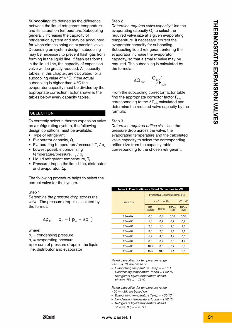
Table 2: Fixed orifices - Rated Capacities in kW
Orifice Size
R22R407C R134a R404A
R507R404AR507
Evaporating Temperature Range [°C]
- 40 ➝ + 10 -60➝ -25
23--/-0X
23--/-00
23--/-01
23--/-02
23--/-03
23--/-04
23--/-05
23--/-06
0,5
1,0
2,5
3,5
5,2
8,0
10,5
15,5
0,4
0,9
1,8
2,6
4,6
6,7
8,6
10,5
0,38
0,7
1,6
2,1
4,2
6,0
7,7
9,1
0,38
0,7
1,6
2,1
3,5
4,9
6,0
6,6
Rated capacities, for temperature range - 40 ➝ + 10, are based on:– Evaporating temperature Tevap = + 5 °C– Condensing temperature Tcond = + 32 °C– Refrigerant liquid temperature ahead
of valve Tliq = + 28 °C
Rated capacities, for temperature range - 60 ➝ - 25, are based on:– Evaporating temperature Tevap = - 30 °C– Condensing temperature Tcond = + 32 °C– Refrigerant liquid temperature ahead
of valve Tliq = + 28 °C

77
85
54 3440
108
39
32 www.castel.it
STEP 1 - Determine the pressure dropacross the valve• Condensing pressure at
+ 38 °C - Pc = 13,6 bar• Evaporating pressure at
+ 5 °C - Pe = 4.8 bar
STEP 2 - Determine required valve capacity
From the subcooling corrector factor table3b we find the appropriate corrector factorFsub equal to 1,07 for �Tsub = 11 °C. Required valve capacity is:
STEP 3 - Determine required orifice sizeUsing the capacity table for R22 on page 33with:• pressure drop across the valve = 8,3 bar• evaporating temperature = + 5 °C• calculated evaporator capacity = 3,55 kW• select the corresponding valve 23--/-02
(N.B.: the expansion valve capacity mustbe equal or slightly more than thecalculated evaporator capacity)
kW3,551,078,3Q sub ⋅==∆
C112738Tsub °⋅=−=∆
( ) bar3,85,08,46,13ptot ⋅=+−=∆
Step 4Select a thermostatic charge. Chose thetype of charge, liquid without MOP or gaswith MOP, and the temperature range,normal temperature or low temperature.
Step 5Determine if external equalizer is required.External equalizer is always required if adistributor is used or if there is anappreciable difference in pressure from thevalve outlet to the bulb location. Finallydetermine the type of connections and theirsizes.
• Type of refrigerant R22• Evaporator capacity, Qe 3,8 kW• Evaporating temperature/
pressure, Te + 5 °C• Lowest possible condensing
temperature/pressure, Tc + 38 °C• Liquid refrigerant temperature,Tl + 27 °C• Pressure drop in the liquid line, distributor
and evaporator, �p 0,5 bar
SIZING EXAMPLE

33
TH
ER
MO
STA
TIC
EX
PAN
SIO
N VA
LVE
S
www.castel.it
The following data are indicated on theupper side of the thermostatic element ofthe valve:• The valve code number• The refrigerant• The evaporating temperature range• The MOP value, if present• The maximum allowable pressure PS• The date of production• The size of the orifice
MARKING
Table 3a: Refrigerant R22/R407C - Capacities in kW for temperature range - 40°C ➝➝ + 10°C
Orificesize
Orificesize
Pressure drop across valve [bar] Pressure drop across valve [bar]
2 4 6 8 10 12 14 16 2 4 6 8 10 12 14 16
Evaporating temperature = 0 °C
23--/-0X 0,37 0,48 0,55 0,59 0,63 0,65 0,66 0,66
23--/-00 0,84 1,0 1,2 1,3 1,3 1,4 1,4 1,4
23--/-01 1,9 2,4 2,7 3,0 3,1 3,2 3,3 3,3
23--/-02 2,6 3,4 4,0 4,3 4,6 4,8 4,9 5,0
23--/-03 4,6 6,1 7,1 7,8 8,2 8,5 8,7 8,8
23--/-04 6,9 9,1 10,5 11,5 12,2 12,7 13,0 13,2
23--/-05 8,8 11,6 13,3 14,6 15,5 16,1 16,4 16,6
23--/-06 10,8 14,2 16,3 17,8 18,9 19,6 20,0 20,2
Evaporating temperature = -20 °C
23--/-0X 0,44 0,50 0,54 0,57 0,59 0,61 0,61
23--/-00 0,88 1,0 1,1 1,1 1,2 1,2 1,2
23--/-01 1,7 1,9 2,0 2,2 2,3 2,3 2,3
23--/-02 2,4 2,7 2,9 3,1 3,2 3,3 3,3
23--/-03 4,2 4,8 5,2 5,5 5,8 5,9 6,0
23--/-04 6,2 7,1 7,7 8,2 8,5 8,7 8,8
23--/-05 7,9 9,0 9,8 10,3 10,8 11,0 11,2
23--/-06 9,6 11,0 11,9 12,6 13,1 13,5 13,7
Evaporating temperature = -40 °C
23--/-0X 0,42 0,45 0,48 0,50 0,52 0,53
23--/-00 0,8 0,86 0,92 0,95 0,98 0,99
23--/-01 1,3 1,4 1,4 1,5 1,5 1,6
23--/-02 1,7 1,9 2,0 2,0 2,1 2,1
23--/-03 3,1 3,4 3,5 3,7 3,8 3,8
23--/-04 4,6 4,9 5,2 5,4 5,6 5,7
23--/-05 5,8 6,3 6,6 6,9 7,1 7,2
23--/-06 7,1 7,7 8,1 8,4 8,7 8,8
Evaporating temperature = +10 °C
23--/-0X 0,37 0,48 0,55 0,60 0,63 0,65 0,65 0,67
23--/-00 0,87 1,1 1,2 1,3 1,4 1,4 1,4 1,5
23--/-01 2,2 2,8 3,2 3,4 3,6 3,7 3,8 3,8
23--/-02 3,0 4,0 4,7 5,1 5,4 5,6 5,8 5,8
23--/-03 5,4 7,2 8,3 9,1 9,7 10,0 10,2 10,3
23--/-04 8,1 10,8 12,5 13,8 14,5 15,0 15,5 15,5
23--/-05 10,2 13,6 15,7 17,2 18,3 18,9 19,3 19,5
23--/-06 12,6 16,7 19,3 21,0 22,3 23,1 23,5 23,7
Evaporating temperature = -10 °C
23--/-0X 0,37 0,47 0,53 0,57 0,60 0,63 0,64 0,64
23--/-00 0,79 0,96 1,1 1,2 1,2 1,3 1,3 1,3
23--/-01 1,6 2,0 2,3 2,5 2,6 2,7 2,8 2,8
23--/-02 2,2 2,9 3,3 3,6 3,8 4,0 4,1 4,1
23--/-03 3,9 5,1 5,9 6,4 6,8 7,1 7,3 7,3
23--/-04 5,8 7,6 8,7 9,5 10,1 10,5 10,8 10,9
23--/-05 7,4 9,6 11,0 12,0 12,8 13,3 13,6 13,8
23--/-06 9,1 11,6 13,5 14,7 15,6 16,2 16,6 16,8
Evaporating temperature = -30 °C
23--/-0X 0,40 0,45 0,49 0,52 0,55 0,56 0,57
23--/-00 0,79 0,9 0,96 1,0 1,1 1,1 1,1
23--/-01 1,4 1,5 1,7 1,8 1,8 1,9 1,9
23--/-02 1,9 2,2 2,7 2,5 2,6 2,6 2,7
23--/-03 3,4 3,9 4,2 4,4 4,6 4,7 4,8
23--/-04 5,0 5,7 6,2 6,6 6,8 7,0 7,1
23--/-05 6,4 7,2 7,8 8,3 8,6 8,8 9,0
23--/-06 7,8 8,8 9,6 10,1 10,5 10,8 11,0
Table 3b: Refrigerant R22/R407C - Correction factor for subcooling �tsub > 4°C
�tsub [°C] 4 10 15 20 25 30 35 40 45 50
Fsub 1,00 1,06 1,11 1,15 1,20 1,25 1,30 1,35 1,39 1,44
When subcooling ahead of the expansion valve is other than 4 °C, adjust the evaporatore capacity by dividing bythe appropriate correction factor found in Table 3b

34 www.castel.it
Table 4a: Refrigerant R134a - Capacities in kW for temperature range - 40°C ➝➝ + 10°C
Orificesize
Orificesize
Pressure drop across valve [bar] Pressure drop across valve [bar]
2 4 6 8 10 2 4 6 8 10
Evaporating temperature = 0 °C
23--/-0X 0,33 0,42 0,46 0,47 0,49
23--/-00 0,65 0,78 0,86 0,89 0,91
23--/-01 1,3 1,6 1,7 1,8 1,8
23--/-02 1,7 2,2 2,4 2,6 2,6
23--/-03 3,0 3,9 4,4 4,6 4,7
23--/-04 4,5 5,7 6,4 6,8 7,0
23--/-05 5,7 7,3 8,1 8,6 8,8
23--/-06 7,0 8,9 1,0 10,5 10,8
Evaporating temperature = -20 °C
23--/-0X 0,28 0,35 0,39 0,41 0,42
23--/-00 0,53 0,62 0,69 0,72 0,73
23--/-01 0,81 1,0 1,1 1,2 1,2
23--/-02 1,1 1,4 1,5 1,6 1,7
23--/-03 2,0 2,5 2,8 2,9 3,0
23--/-04 2,9 3,6 4,0 4,3 4,4
23--/-05 3,7 4,6 5,1 5,4 5,5
23--/-06 4,5 5,6 6,2 6,6 6,8
Evaporating temperature = -40 °C
23--/-0X 0,23 0,28 0,32 0,33 0,34
23--/-00 0,44 0,50 0,54 0,56 0,57
23--/-01 0,54 0,65 0,72 0,78 0,77
23--/-02 0,7 0,9 1,0 1,0 1,0
23--/-03 1,3 1,6 1,8 1,9 1,9
23--/-04 1,9 2,3 2,6 2,7 2,7
23--/-05 2,4 2,9 3,2 3,5 3,5
23--/-06 3,0 3,6 4,0 4,2 4,3
Evaporating temperature = +10 °C
23--/-0X 0,34 0,43 0,47 0,50 0,51
23--/-00 0,71 0,86 0,93 0,97 0,98
23--/-01 1,5 1,9 2,1 2,2 2,2
23--/-02 2,0 2,6 3,0 3,1 3,2
23--/-03 3,6 4,7 5,3 5,6 5,8
23--/-04 5,4 7,0 7,8 8,3 8,6
23--/-05 6,9 8,9 9,9 10,8 10,9
23--/-06 8,4 10,8 12,1 12,8 13,2
Evaporating temperature = -10 °C
23--/-0X 0,30 0,36 0,43 0,44 0,44
23--/-00 0,59 0,70 0,77 0,81 0,82
23--/-01 1,0 1,3 1,4 1,5 1,5
23--/-02 1,4 1,8 2,0 2,1 2,1
23--/-03 2,5 3,1 3,5 3,7 3,8
23--/-04 3,6 4,6 5,1 5,4 5,6
23--/-05 4,6 5,8 6,5 6,9 7,1
23--/-06 5,7 7,1 8,0 8,4 8,6
Evaporating temperature = -30 °C
23--/-0X 0,25 0,32 0,35 0,37 0,38
23--/-00 0,48 0,55 0,61 0,64 0,64
23--/-01 0,66 0,80 0,88 0,93 0,95
23--/-02 0,9 1,1 1,2 1,3 1,3
23--/-03 1,6 2,0 2,2 2,3 2,3
23--/-04 2,3 2,9 3,2 3,3 3,4
23--/-05 3,0 3,6 4,0 4,2 4,3
23--/-06 3,6 4,4 4,9 5,2 5,3
Table 4b: Refrigerant R134a - Correction factor for subcooling �tsub > 4°C
�tsub [°C] 4 10 15 20 25 30 35 40 45 50
Fsub 1,00 1,08 1,13 1,19 1,25 1,31 1,37 1,42 1,48 1,54
When subcooling ahead of the expansion valve is other than 4 °C, adjust the evaporatore capacity by dividing bythe appropriate correction factor found in Table 4b

35
TH
ER
MO
STA
TIC
EX
PAN
SIO
N VA
LVE
S
www.castel.it
Table 5a: Refrigerant R404A/R507 - Capacities in kW for temperature range - 40°C ➝➝ + 10°C
Orificesize
Orificesize
Pressure drop across valve [bar] Pressure drop across valve [bar]
2 4 6 8 10 12 14 16 2 4 6 8 10 12 14 16
Evaporating temperature = 0 °C
23--/-0X 0,30 0,37 0,41 0,42 0,43 0,43 0,43 0,41
23--/-00 0,68 0,80 0,87 0,90 0,92 0,93 0,91 0,87
23--/-01 1,53 1,86 2,04 2,13 2,18 2,18 2,15 2,08
23--/-02 2,06 2,64 2,95 3,13 3,22 3,25 3,21 3,11
23--/-03 3,68 4,72 5,27 5,59 5,75 5,80 5,73 5,55
23--/-04 5,49 7,15 7,86 8,33 8,58 8,64 8,53 8,27
23--/-05 6,97 8,92 9,95 10,52 10,83 10,90 10,76 10,43
23--/-06 8,57 10,93 12,16 12,85 13,21 13,30 13,12 12,72
Evaporating temperature = -20 °C
23--/-0X 0,35 0,38 0,40 0,39 0,40 0,39 0,38
23--/-00 0,70 0,75 0,77 0,79 0,79 0,79 0,76
23--/-01 1,34 1,45 1,50 1,52 1,52 1,51 1,47
23--/-02 1,85 2,04 2,14 2,17 2,18 2,16 2,09
23--/-03 3,32 3,66 3,83 3,89 3,90 3,86 3,75
23--/-04 4,88 5,40 5,64 5,75 5,77 5,71 5,56
23--/-05 6,20 6,86 7,17 7,29 7,31 7,23 7,05
23--/-06 7,60 8,39 8,75 8,91 8,93 8,84 8,61
Evaporating temperature = -40 °C
23--/-0X 0,32 0,33 0,33 0,33 0,32 0,32
23--/-00 0,60 0,61 0,62 0,61 0,60 0,59
23--/-01 0,92 0,96 0,97 0,96 0,94 0,91
23--/-02 1,27 1,32 1,33 1,31 1,28 1,24
23--/-03 2,28 2,36 2,38 2,36 2,31 2,24
23--/-04 3,34 3,47 3,50 3,48 3,42 3,33
23--/-05 4,25 4,41 4,45 4,43 4,36 4,24
23--/-06 5,19 5,39 5,45 5,42 5,33 5,19
Evaporating temperature = +10 °C
23--/-0X 0,28 0,35 0,40 0,42 0,43 0,43 0,42 0,41
23--/-00 0,67 0,82 0,90 0,94 0,96 0,96 0,93 0,90
23--/-01 1,70 2,10 2,30 2,42 2,48 2,46 2,41 2,34
23--/-02 2,32 3,00 3,39 3,61 3,73 3,74 3,68 3,59
23--/-03 4,15 5,36 6,03 6,43 6,63 6,66 6,55 6,39
23--/-04 6,24 8,06 9,06 9,66 9,95 9,98 9,81 9,57
23--/-05 7,91 10,17 11,43 12,16 12,53 12,56 12,34 12,03
23--/-06 9,71 12,47 13,98 14,86 15,29 15,31 15,05 14,66
Evaporating temperature = -10 °C
23--/-0X 0,30 0,37 0,40 0,42 0,42 0,42 0,41 0,41
23--/-00 0,65 0,76 0,82 0,84 0,87 0,87 0,85 0,83
23--/-01 1,31 1,61 1,74 1,81 1,84 1,85 1,84 1,78
23--/-02 1,76 2,24 2,50 2,62 2,69 2,71 2,68 2,60
23--/-03 3,14 4,02 4,47 4,69 4,81 4,84 4,79 4,65
23--/-04 4,66 5,97 6,61 6,95 7,13 7,18 7,11 6,91
23--/-05 5,93 7,57 8,39 8,81 9,02 9,08 8,99 8,73
23--/-06 7,28 9,27 10,26 10,76 11,00 11,08 10,97 10,65
Evaporating temperature = -30 °C
23--/-0X 0,35 0,37 0,36 0,37 0,36 0,35
23--/-00 0,67 0,70 0,70 0,70 0,69 0,67
23--/-01 1,18 1,21 1,23 1,21 1,20 1,17
23--/-02 1,63 1,69 1,71 1,70 1,68 1,64
23--/-03 2,93 3,04 3,07 3,06 3,02 2,93
23--/-04 4,28 4,47 4,52 4,51 4,46 4,35
23--/-05 5,45 5,68 5,74 5,74 5,67 5,52
23--/-06 6,66 6,94 7,02 7,01 6,93 6,75
Table 5b: Refrigerant R404A/R507 - Correction factor for subcooling �tsub > 4°C
�tsub [°C] 4 10 15 20 25 30 35 40 45 50
Fsub 1,00 1,10 1,20 1,29 1,37 1,46 1,54 1,63 1,70 1,78
When subcooling ahead of the expansion valve is other than 4 °C, adjust the evaporatore capacity by dividing bythe appropriate correction factor found in Table 5b

36 www.castel.it
Table 6a: Refrigerant R404A/R507 - Capacities in kW for temperature range - 60°C ➝➝ - 25°C
Orificesize
Orificesize
Pressure drop across valve [bar] Pressure drop across valve [bar]
2 4 6 8 10 12 14 16 2 4 6 8 10 12 14 16
Evaporating temperature = -30 °C
23--/-00 0,53 0,64 0,67 0,70 0,70 0,70 0,69 0,67
23--/-01 0,88 1,07 1,18 1,21 1,23 1,21 1,20 1,17
23--/-02 1,18 1,47 1,63 1,69 1,71 1,70 1,68 1,64
23--/-03 2,12 2,65 2,93 3,04 3,07 3,05 3,02 2,93
23--/-04 3,09 3,88 4,28 4,47 4,52 4,51 4,46 4,35
23--/-05 3,94 4,94 5,45 5,68 5,74 5,74 5,67 5,52
23--/-06 4,83 6,06 6,66 6,94 7,02 7,01 6,93 6,75
Evaporating temperature = -50 °C
23--/-00 0,49 0,53 0,54 0,54 0,53 0,52 0,50
23--/-01 0,51 0,57 0,60 0,60 0,60 0,60 0,59
23--/-02 0,91 0,99 1,02 1,02 1,01 0,98 0,95
23--/-03 1,63 1,73 1,84 1,84 1,81 1,78 1,72
23--/-04 2,36 2,60 2,69 2,71 2,68 2,63 2,56
23--/-05 3,02 3,30 3,43 3,45 3,42 3,35 3,26
23--/-06 3,69 4,04 4,20 4,22 4,18 4,12 4,00
Evaporating temperature = -25 °C
23--/-00 0,57 0,67 0,72 0,73 0,74 0,85 0,74 0,71
23--/-01 0,98 1,20 1,31 1,36 1,37 1,37 1,35 1,31
23--/-02 1,31 1,65 1,83 1,91 1,93 1,93 1,90 1,85
23--/-03 2,35 2,97 3,28 3,42 3,47 3,46 3,42 3,32
23--/-04 3,45 4,37 4,82 5,04 5,11 5,12 5,06 4,93
23--/-05 4,40 5,56 6,14 6,40 6,49 6,49 6,42 6,26
23--/-06 5,40 6,30 7,49 7,81 7,93 7,93 7,85 7,64
Evaporating temperature = -40 °C
23--/-00 0,56 0,60 0,61 0,62 0,61 0,60 0,59
23--/-01 0,65 0,72 0,75 0,77 0,77 0,77 0,75
23--/-02 1,17 1,27 1,32 1,33 1,31 1,28 1,24
23--/-03 2,09 2,28 2,36 2,38 2,36 2,31 2,24
23--/-04 3,03 3,34 3,47 3,50 3,48 3,42 3,33
23--/-05 3,87 4,25 4,41 4,45 4,43 4,36 4,24
23--/-06 4,73 5,19 5,39 5,45 5,47 5,33 5,19
Evaporating temperature = -60 °C
23--/-00 0,46 0,48 0,47 0,45 0,45 0,43
23--/-01 0,58 0,60 0,60 0,58 0,56 0,54
23--/-02 0,78 0,80 0,80 0,78 0,75 0,72
23--/-03 1,40 1,44 1,43 1,40 1,36 1,30
23--/-04 2,04 2,11 2,11 2,07 2,03 1,96
23--/-05 2,59 2,69 2,66 2,65 2,59 2,50
23--/-06 3,16 3,28 3,30 3,25 3,18 3,07
Table 6b: Refrigerant R404A/R507 - Correction factor for subcooling �tsub > 4°C
�tsub [°C] 4 10 15 20 25 30 35 40 45 50
Fsub 1,00 1,10 1,20 1,29 1,37 1,46 1,54 1,63 1,70 1,78
When subcooling ahead of the expansion valve is other than 4 °C, adjust the evaporatore capacity by dividing bythe appropriate correction factor found in Table 6b