thermo scientific thermoflextm
TRANSCRIPT

Visit our Web site at:
http://www.thermoscientific.com/tcProduct Service Information, Applications Notes, MSDS Forms, e-mail.
Voice Info: (800) 258-0830
Thermo Scientific ThermoFlexTM Recirculating Chillers (Basic Controller)
Thermo Scientific Manual P/N U00933 Rev. 01/03/2013
Installation
Operation
Basic Maintenance


Visit our Web site at:
http://www.thermoscientific.com/tcProduct Service Information, Applications Notes, MSDS Forms, e-mail.
Voice Info: (800) 258-0830
Thermo ScientificThermoFlexTM
Recirculating Chillers (Basic Controller)Thermo Scientific Manual P/N U00933 Rev. 01/03/2013
Installation Operation
Basic Maintenance
Label 1
Label 2

Thermo Fisher Scientific
25 Nimble Hill RoadNewington, NH 03801Tel : (800) 258-0830 or(603) 436-9444Fax : (603) 436-8411www.thermoscientific.com/tc
Sales, Service, and Customer Support
25 Nimble Hill RoadNewington, NH 03801Tel: (800) 258-0830 Sales: 8:00 am to 5:00 pmService and Support: 8:00 am to 6:00 pm Monday through Friday (Eastern Time)Fax: (603) [email protected]
Dieselstrasse 4 D-76227 Karlsruhe, Germany Tel : +49 (0) 721 4094 444 Fax : +49 (0) 721 4094 [email protected]
Building 6, No. 27Xin Jinqiao Rd., Shanghai 201206Tel : +86(21) 68654588Fax : +86(21) [email protected]
Ion Path, Road Three, Winsford, Cheshire, CW73GA, United KingdomPhone: +44 (0)8706 099254Fax: +44 (0)1606 548103
Statement of Copyright Copyright © 2013 Thermo Fisher Scientific. All rights reserved. This manual is copyrighted by Thermo Fisher Scientific. Users are forbidden to reproduce, republish, redistribute, or resell any materials from this manual in either machine-readable form or any other form.

ThermoFlex Thermo Scientific
Contents
Quick Start
Preface .................................................................................................................................i Compliance ..............................................................................................................i WEEE .....................................................................................................................i After-Sale Support .................................................................................................ii Unpacking ...............................................................................................................ii Warranty ..................................................................................................................ii Feedback ..................................................................................................................ii
Section 1 Safety ..................................................................................1-1 Warnings ..............................................................................................................1-1
Section 2 General Information .............................................................2-1 Description .........................................................................................................2-1 Specifications ......................................................................................................2-1
Section 3 Installation ...........................................................................3-1 Site Requirements ..............................................................................................3-1 Electrical Requirements ....................................................................................3-2 Hard Wire Installation .......................................................................................3-8 Plumbing Requirements ....................................................................................3-9 Process Fluid Requirements ...........................................................................3-11 Compatibility with Approved Fluids ............................................................3-12 Additional Fluid Information ........................................................................3-14 Process Water Quality and Standards ...........................................................3-14 Facility Water Quality - Standards and Recommendations (water-cooled chillers) ...................................................3-15 Facility Water Requirements (water-cooled chillers) ...................................3-17 Initial Filling .....................................................................................................3-18 Fluid Top Off ...................................................................................................3-19
Section 4 Operation .........................................................................................................4-1 Basic Controller ..................................................................................................4-1 Setup ....................................................................................................................4-2 Start Up ...............................................................................................................4-2 Controller Loops ................................................................................................4-4 Setpoint Loop .....................................................................................................4-5 Setup Loop ..........................................................................................................4-6 Shut Down ........................................................................................................4-12

ThermoFlex
Contents
Thermo Scientific
Section 5 Additional Options/Accessories ................................................5-1 AutoRefill .........................................................................................................5-1 Internal DI Cartridge ........................................................................................5-2 P1P2T1PumpPressureRelief Valve(InternalConfiguration) .............. 5-3 P1P2T1PumpPressureRelief Valve(ExternalConfiguration) ............. 5-4 Flow Control with Flow Readout ....................................................................5-5 P 1 P 2 T1 Pump Pressure Relief with Flow Readout .................................. 5-5 Anti Drainback ...................................................................................................5-6 SEMI ....................................................................................................................5-6 Other Accessories ............................................................................................5-10
Section 6 Preventive Maintenance............................................................................... 6-1 Preventive Maintenance Timer .......................................................................6-1 Fluid Bag Filter ...................................................................................................6-2 Fluid Diffuser .....................................................................................................6-2 Reservoir Cleaning .............................................................................................6-3 Fluid Maintenance .............................................................................................6-3 Condenser Filter .................................................................................................6-4 Chiller Surface ....................................................................................................6-5 Hoses ...................................................................................................................6-5 DI Filter (Optional) ..........................................................................................6-6 Testing the Safety Features ...............................................................................6-7 Diagnostic Loop ...............................................................................................6-7
Section 7 Troubleshooting .....................................................................7-1 Operational Error Codes ..................................................................................7-1 Checklist ............................................................................................................7-10 Verifying/Adjusting the Controller PID Values .........................................7-13
Section 8 Additional Information ............................................................8-1 Draining ...............................................................................................................8-1 Wetted Materials .................................................................................................8-3 Internal Process Fluid Temperature Sensor (rdt1) Calibration ................... 8-4 Process Fluid Pressure (P 1) Transducer Calibration ................................... 8-6 Optional Process Fluid Flow (FLo) Transducer Calibration ...................... 8-8 Clearing SEr1 Message ....................................................................................8-10 Shipment/Storage ............................................................................................8-10
Appendix A CountrySpecific230VAC,50Hz,1ØRequirements
Appendix B VoltageConfigurationInstructions
Appendix C Analog I/0 and Remote Sensor
Appendix D Serial Communications
Declaration of Conformity WARRANTY

MIN
LEVE
L
MA
XLE
VEL
Slo
wly
fill
rese
rvoi
r with
cle
an p
roce
ss fl
uid
(see
Tab
le 1
), ut
ilizi
ng s
ight
tube
for e
asy flu
id le
vel m
onito
ring.
Whe
n th
e re
ser-
voir
is fu
ll re
plac
e th
e re
serv
oir c
ap, h
and
tight
. Sin
ce th
e re
serv
oir
capa
city
may
be
smal
l com
pare
d to
you
r app
licat
ion
and
air m
ay
need
to b
e pu
rged
from
the
lines
, hav
e ex
tra c
oolin
g flu
id o
n ha
nd
to k
eep
the
syst
em to
pped
off
whe
n ex
tern
al c
ircul
atio
n is
sta
rted.
Pre
ss
.
The
cont
rolle
r will
dis
play
SEt
uP.
Not
e: If
the
unit
is e
quip
ped
with
a d
eion
izat
ion fil
ter c
artri
dge
refe
r to
the
man
ual,
Sec
tion
5, fo
r ins
talla
tion.
Plea
se s
ee re
vers
e si
de fo
r add
ition
al s
teps
.
Pul
l out
the
plas
tic s
hipp
ing
plug
s. R
emov
e th
e re
serv
oir c
ap b
y un
scre
win
g it
coun
ter-
cloc
kwis
e.
Ver
ify th
e ap
prop
riate
vol
tage
. For
uni
ts s
uppl
ied
with
a li
ne c
ord,
in
sert
fem
ale
end
of p
ower
cor
d in
to c
hille
r and
then
inse
rt m
ale
end
of p
ower
cor
d in
to p
ower
out
let.
(The
line
cor
d is
loca
ted
unde
r the
sh
ippi
ng c
rate
’s li
d. D
o no
t dis
card
the
lid
until
the
cord
is lo
cate
d.)
Con
nect
the
Ther
moF
lex
FA
CIL
ITY
OU
TLE
T (A
) to
your
faci
lity
wat
er re
turn
or d
rain
. C
onne
ct th
e Th
erm
oFle
x FA
CIL
ITY
INLE
T (B
) to
you
r fac
ility
wat
er s
uppl
y. E
nsur
e th
e co
nnec
tions
are
sea
led
and
secu
re.
Wha
t you
nee
d to
get
sta
rted
:• A
n ad
just
able
wre
nch
• Fac
ility
wat
er s
uppl
y an
d re
turn
(wat
er-c
oole
d un
its)
• App
ropr
iate
hos
e or
plu
mbi
ng• A
ppro
pria
te s
ize
clam
ps o
r con
nect
ion
type
• Tefl
on® T
ape
or a
ppro
pria
te s
eala
nt
Safe
ty P
reca
utio
ns:
The
unit
is d
esig
ned
for i
ndoo
r use
onl
y.
Nev
er p
lace
uni
t in
a lo
catio
n w
here
exc
essi
ve h
eat,
moi
stur
e, in
adeq
uate
ve
ntila
tion,
or c
orro
sive
mat
eria
ls a
re p
rese
nt.
Nev
er c
onne
ct p
roce
ss fl
uid
lines
to y
our f
acili
ty w
ater
sup
ply
or to
any
pr
essu
rized
liqu
id s
ourc
e.
If yo
ur u
nit i
s eq
uipp
ed w
ith a
pos
itive
dis
plac
emen
t pum
p (P
1 or
P2)
, en
sure
you
r app
licat
ion
plum
bing
line
s an
d fit
tings
are
rate
d to
with
stan
d a
min
imum
of 1
85 p
si.
Bef
ore
usin
g an
y flu
id o
r per
form
ing
mai
nten
ance
whe
re c
onta
ct w
ith th
e flu
id is
like
ly re
fer t
o th
e m
anuf
actu
rer’s
MS
DS
for h
andl
ing
prec
autio
ns.
For w
ater
-coo
led
units
onl
y.
See
Fig
ure
A.
See
Fig
ure
B.
See
Fig
ure
B.
See
Fig
ure
B.
See
Fig
ure
B.
See
Fig
ure
B.
See
Fig
ure
A.
See
Fig
ure
A.
Con
nect
the
Ther
moF
lex
PR
OC
ES
S O
UTL
ET
(A) t
o th
e flu
id in
let
on y
our a
pplic
atio
n. C
onne
ct th
e Th
erm
oFle
x P
RO
CE
SS
INLE
T (B
) to
the flu
id o
utle
t on
your
app
licat
ion.
Ens
ure
the
conn
ectio
ns a
re s
eale
d an
d se
cure
. For
air-
cool
ed u
nits
ski
p to
Ste
p 4.
For
The
rmoF
lex9
00 th
roug
h 10
000
units
, pla
ce th
e ci
rcui
t pr
otec
tor t
o th
e on
( I )
pos
ition
. The
con
trolle
r dis
play
will
indi
cate
a
serie
s of
scr
ollin
g ba
rs (
). T
he b
ars
will
scr
oll u
pwar
d in
dica
ting
the
unit
is in
itial
izin
g, th
is ta
kes
appr
oxim
atel
y 15
sec
-on
ds. F
or o
ther
uni
ts th
e ba
rs a
ppea
r whe
n po
wer
is s
uppl
ied
to
the
unit.
B
A
B
A
PRO
CES
SIN
LET
PRO
CES
SO
UTL
ET
FAC
ILIT
YIN
LET
FAC
ILIT
YO
UTL
ET
Not
e: B
e ca
refu
l not
to
fill
the
rese
rvoi
r ab
ove
MA
X L
EV
EL fil
l lin
e. T
his
will
resu
lt in
a
unit
over
flow
err
or
(O F
LO) w
hich
will
ca
use
the
unit
to s
hut
dow
n.
Ther
mo
Sci
entifi
c P
art N
umbe
r U00
945
Rev
. 11/
19/2
012
Not
e: T
herm
oFle
x900
-500
0 un
its e
quip
ped
with
the
Varia
ble
Volta
ge o
r Glo
bal V
olta
ge
optio
n ha
ve a
vol
tage
config
urat
ion
pane
l lo
cate
d be
hind
an
acce
ss p
anel
on
the
rear
of
the
unit.
Ref
er to
the
Volta
ge In
stru
ctio
n S
heet
shi
pped
with
the
unit,
or s
ee m
anua
l A
ppen
dix
B.
Not
e: F
or u
nits
requ
iring
har
d w
iring
see
S
ectio
n 3
in th
e m
anua
l.
Wat
er-c
oole
d un
its o
nly
FAC
ILIT
YIN
LET
FAC
ILIT
YO
UTL
ET
PRO
CES
SIN
LET
PRO
CES
SO
UTL
ET
Use
of a
ny fl
uid
not l
iste
d be
low
will
voi
d th
e m
anuf
actu
rer’s
war
rant
y.
Fi
ltere
d/S
ingl
e D
istil
led
Wat
er
D
eion
ized
wat
er (1
-3 MΩ
-cm
, com
pens
ated
)
0
– 75
% E
thyl
ene
Gly
col/W
ater
0
– 75
% P
ropy
lene
Gly
col/W
ater
Tabl
e 1
- Acc
epta
ble
Flui
ds:
Faci
lity
Wat
er C
onne
ctio
ns (F
NP
T)Th
erm
oFle
x140
0 - 5
000
Inle
t/Out
let ½
” cas
t bro
nze
Ther
moF
lex7
500
- 100
00 In
let/O
utle
t ¾” c
ast b
ronz
eTh
erm
oFle
x150
00 -
2400
0 In
let ¾
” cas
t bro
nze
Ther
moF
lex1
5000
- 24
000
Out
let ¾
” sta
inle
ss s
teel
Con
trolle
r S
ee S
tep
8.
Pow
er B
utto
n S
ee S
tep
8.
Inte
grat
ed F
unne
l S
ee S
tep
5.
Leve
l Ind
icat
or
See
Ste
p 5.
Figu
re A
Res
ervo
ir C
ap
See
Ste
p 4.
Pro
cess
Out
let -
S
ee S
teps
1 a
nd 2
.
Pro
cess
Out
let -
(T
herm
oFle
x900
-50
00 u
nits
with
PD
pu
mps
and
flow
tra
nsdu
cers
)
Circ
uit P
rote
ctor
S
ee S
tep
7.
Pow
er In
let f
or u
nits
no
t har
d-w
ired
See
Ste
p 6.
Pro
cess
Inle
t -S
ee S
teps
1 a
nd 2
.
Faci
lity
Inle
tS
ee S
teps
1 a
nd 3
.
Faci
lity
Out
let
See
Ste
ps 1
and
3.
Wat
er-c
oole
d un
its o
nly
Figu
re B
Figu
re B
is ty
pica
l.
Loca
tions
var
y w
ith u
nit s
ize
and
sele
cted
opt
ions
. The
labe
ls id
entif
y th
e ex
act l
ocat
ion.
Loca
tions
var
y w
ith
unit
size
and
sel
ecte
d op
tions
. The
la
bels
iden
tify
the
exac
t lo
catio
n.
Pro
cess
Flu
id C
onne
ctio
ns (F
NP
T)O
utle
t Th
erm
oFle
x900
- 10
000
P
1 P
2 T0
T 1
1/
2" c
ast b
ronz
eTh
erm
oFle
x350
0 - 5
000
P
3 P
4
3/4"
cas
t bro
nze
Ther
moF
lex7
500
- 240
00
P 3
P 5
T 5
1" w
roug
ht c
oppe
rIn
let -
Sam
e si
ze a
s ou
tlet
al
l uni
ts s
tain
less
ste
elS
uppl
ied
Ada
pter
sP
1 P
2 T0
T 1
1/
2" x
3/8
'' Pol
yeth
ylen
e an
d 1/
2" x
1/2
" Nyl
on
P 3
P 4
3/
4 M
PT
x 1/
2 ba
rb P
VC
P 3
P 5
T 5
1" M
PT
x 1"
Bar
b P
VC
and
1" M
PT
x 3/
4" B
arb
PV
C

• Pre
ss
• The
dis
play
will
fl as
h be
twee
n H
i t a
nd 4
2
• If d
esire
d, u
se
to a
djus
t the
val
ue
• Pre
ss
to s
eque
nce
to th
e ne
xt d
ispl
ay
• Pre
ss
• The
dis
play
will
fl as
h be
twee
n Lo
t an
d 3
• If d
esire
d, u
se
to a
djus
t the
val
ue
• Pre
ss
Lo t
sets
the
fl uid
’s L
ow
Tem
pera
ture
Ala
rm L
imit.
Ran
ge: +
3°C
to +
42°C
Fact
ory
Def
ault:
3°C
• Pre
ss
• The
dis
play
will
fl as
h be
twee
n H
i P1
and
the
defa
ult
• If d
esire
d, u
se
to a
djus
t the
val
ue
• Pre
ss
Hi P
1 se
ts th
e Pu
mp’
s H
igh
Pres
sure
Dis
char
ge A
larm
Lim
it.
Ran
ge: V
arie
s by
pum
pFa
ctor
y D
efau
lt: V
arie
s by
pum
p
• The
dis
play
will
fl as
h be
twee
n dE
LAY
and
0
• If d
esire
d, u
se
to a
djus
t th
e va
lue
• Pre
ss
dELA
Y is
the
leng
th o
f tim
e th
e pu
mp
can
exce
ed th
e H
i P1
Ala
rm L
imit
befo
re s
hutti
ng d
own.
Ran
ge: V
arie
s by
pum
pFa
ctor
y D
efau
lt: 0
sec
onds
• Pre
ss
• The
dis
play
will
fl as
h be
twee
n Lo
P1
and
the
defa
ult
• If d
esire
d, u
se
to a
djus
t the
def
ault
• Pre
ss
Lo P
1 se
ts th
e Pu
mp’
s Lo
w
Pres
sure
Dis
char
ge A
larm
Li
mit.
Ran
ge: V
arie
s by
pum
pFa
ctor
y D
efau
lt: V
arie
s by
pum
p
dELA
Y is
the
leng
th o
f tim
e th
e pu
mp
can
exce
ed th
e Lo
P1
Ala
rm L
imit
befo
re s
hutti
ng d
own.
Ran
ge: 0
to 3
0 se
cond
sFa
ctor
y D
efau
lt: 1
0 se
cond
s
• The
dis
play
will
fl as
h be
twee
n dE
LAY
and
10
• If d
esire
d, u
se
to a
djus
t the
val
ue
• Pre
ss
• Pre
ss
• The
dis
play
will
fl as
h be
twee
n A
Lr a
nd fL
t
• If d
esire
d, p
ress
to
dis
play
indC
• Pre
ss
Turn
s th
e un
it’s
audi
ble
alar
m
on o
r off.
Ran
ge: o
n or
OFF
Fact
ory
Def
ault:
on
• Pre
ss
• The
dis
play
will
fl as
h be
twee
n So
und
and
on
• If d
esire
d, p
ress
to
dis
play
OFF
• Pre
ss
• Pre
ss
• The
dis
play
will
fl as
h be
twee
n St
Art
and
OFF
• If d
esire
d, p
ress
to
dis
play
on
• Pre
ss
StA
rt e
nabl
es/d
isab
les
auto
re
star
t.
Ran
ge: o
n or
OFF
Fact
ory
Def
ault:
OFF
• Pre
ss
• The
dis
play
will
fl as
h be
twee
n C
ArE
and
L1
• If d
esire
d, u
se
to c
hang
e di
spla
y to
off,
L2
or L
3
• Pre
ss
CA
rE is
use
d to
set
the
prev
enta
tive
care
cle
anin
g fr
eque
ncy
rem
inde
r for
th
e un
it’s
air a
nd fl
uid
fi lte
rs.
Ran
ge: o
ff, L
1 - 1
000
hour
s,
L2 -
2000
hou
rs, L
3 -3
000
hour
sFa
ctor
y D
efau
lt: L
1
• P
ress
to
sav
e al
l set
tings
Th
e un
it w
ill a
utom
atic
ally
sta
rt.
• P
ress
to
dis
rega
rd a
ll ch
ange
s an
d re
stor
e th
e fa
ctor
y de
faul
t val
ues.
Th
e di
spla
y w
ill g
o bl
ank.
The
Setu
p pr
oced
ure
is n
ow c
ompl
ete.
Whe
n th
e un
it st
arts
the
cont
rolle
r will
di
spla
y th
e pr
oces
s fl u
id te
mpe
ratu
re.
If de
sire
d, y
ou c
an c
hang
e/ve
rify
the
unit’
s se
tpoi
nt b
y pr
essi
ng
.
SP is
use
d to
adj
ust t
he s
etpo
int.
Ran
ge: +
5°C
to +
40°C
Fact
ory
Def
ault:
+20
°C
• The
dis
play
will
fl as
h be
twee
n SP
and
20
• If d
esire
d, u
se
to c
hang
e th
e se
tting
• Pre
ss
to s
ave
the
new
set
poin
t and
retu
rn to
the
tem
pera
ture
dis
play
If ap
plic
able
, see
box
es o
n rig
ht to
set
up
optio
ns. F
or u
nits
with
Ana
log
I/O (A
CO
M) r
efer
to th
e ad
ditio
nal
quic
k st
art s
uppl
ied
with
you
r uni
t.
Qui
ck S
tart
- U
sed
for I
nitia
l Sta
rt U
p O
nly
— p
erfo
rm s
teps
9 to
20
for a
ll un
its.
** fL
t = fa
ult (
shut
dow
n)**
indC
= in
dica
te (c
ontin
ue to
run)
Hi t
set
s th
e fl u
id’s
Hig
h Te
mpe
ratu
re A
larm
Lim
it.
Ran
ge: +
3°C
to +
42°C
Fact
ory
Def
ault:
+42
°C• P
ress
• T
he d
ispl
ay w
ill fl
ash
betw
een
Uni
tS a
nd °C
• If d
esire
d, u
se
to c
hang
e th
e sc
ale
to °
F
• Pre
ss
to s
eque
nce
to th
e ne
xt d
ispl
ay
• Do
the
sam
e fo
r Flo
w a
nd P
ress
ure
scal
es
• Pre
ss
• The
dis
play
will
fl as
h be
twee
n u
id a
nd 1
• If d
esire
d, u
se
to c
hang
e th
e se
tting
• Pre
ss
HiF
LO s
ets
the
high
fl ow
ala
rm
limit.
Ran
ge: V
arie
s by
pum
pFa
ctor
y D
efau
lt: V
arie
s by
pum
p
• Pre
ss
• The
dis
play
will
fl as
h be
twee
n H
iFLO
and
the
defa
ult
• If d
esire
d, u
se
to a
djus
t the
val
ue
• Pre
ss
• Pre
ss
• The
dis
play
will
fl as
h be
twee
n Lo
FLO
and
the
defa
ult
• If d
esire
d, u
se
to a
djus
t the
val
ue
• Pre
ss
LoFL
O s
ets
the
low
fl ow
ala
rm
limit.
Ran
ge: V
arie
s by
pum
pFa
ctor
y D
efau
lt: V
arie
s by
pum
p
• Pre
ss
• The
dis
play
will
fl as
h be
twee
n St
oP a
nd 1
• If d
esire
d, u
se
to c
hang
e th
e se
tting
• Pre
ss
StoP
is u
sed
to in
dica
te th
e nu
mbe
r of s
top
bits
.
Ran
ge: 2
or 1
Fact
ory
Def
ault:
1
u id
(uni
t id)
is u
sed
in R
S485
on
ly. I
dent
ifi es
dev
ices
con
nect
ed
to th
e R
S485
por
t.
Ran
ge: 1
to 9
9Fa
ctor
y D
efau
lt: 1
• Pre
ss
• The
dis
play
will
fl as
h be
twee
n SE
r and
OFF
• If d
esire
d, u
se
to c
hang
e th
e m
ode
• Pre
ss
SEr i
s us
ed to
ena
ble/
disa
ble
and
to c
onfi g
ure
seria
l co
mm
unic
atio
ns m
ode.
Ran
ge: o
ff, rS
232,
rS48
5Fa
ctor
y D
efau
lt: o
ff• P
ress
• T
he d
ispl
ay w
ill fl
ash
betw
een
BA
ud a
nd 9
600
• If
desi
red,
use
to
cha
nge
the
rate
• Pre
ss
BA
ud is
use
d to
sel
ect t
he
baud
rate
(spe
ed) f
or s
eria
l co
mm
unic
atio
n.
Ran
ge: 9
600,
480
0, 2
400,
120
0,
600,
or 3
00 b
its p
er s
econ
d.
• Pre
ss
• The
dis
play
will
fl as
h be
twee
n dA
tA a
nd 8
• Pre
ss
dAtA
is u
sed
to d
ispl
ay th
e nu
mbe
r of b
its.
Dis
play
: 8
• Pre
ss
• The
dis
play
will
fl as
h be
twee
n PA
r and
non
e•
If de
sire
d, u
se
to c
hang
e th
e se
tting
• Pre
ss
PAr i
s us
ed a
s a
mea
ns to
che
ck
for c
omm
unic
atio
n er
rors
.
Ran
ge: e
ven,
odd
, or n
one
Fact
ory
Def
ault:
non
e
Opt
ion
- Flo
w T
rans
duce
r — S
teps
B a
nd C
If yo
ur u
nit d
oes
not h
ave
seria
l com
mun
icat
ions
see
St
ep 2
0.
See
Step
20.
Opt
ion
- Ser
ial C
omm
unic
atio
ns (D
CO
M) —
Ste
ps D
to I
Uni
tS a
re th
e te
mpe
ratu
re, fl
uid
fl o
w (o
ptio
nal)
and
pres
sure
sc
ales
.
Scal
es:
°C/°F
GPM
/LPM
PS
I/Bar
/KPA
S• P
ress
• The
dis
play
will
fl as
h be
twee
n H
Z an
d 60
• If n
eede
d, u
se
to c
hang
e th
e fre
quen
cy
• Pre
ss
If yo
ur u
nit d
oes
not h
ave
a fl o
w
tran
sduc
er o
r ser
ial c
omm
unic
atio
ns
see
Step
20.
Opt
ion
- Vol
tage
— S
tep
A
HZ
is u
sed
to id
entif
y th
e in
com
ing
freq
uenc
y fo
r un
its w
ith P
3 - P
5 pu
mps
and
var
iabl
e vo
ltage
ca
pabi
lity.
The
sel
ecte
d fr
eque
ncy
auto
mat
ical
ly
adju
sts
the
fi rm
war
e's
fi xed
hig
h pr
essu
re
defa
ult s
ettin
g.
II
Pre
ss
to c
ontin
ue th
e se
tup
proc
edur
e.
NO
TE: S
ome
rang
es/d
efau
lts a
re p
ump
depe
nden
t, se
e S
ectio
n 4
in th
e m
anua
l. O
nce
any
Set
up s
tep
is c
ompl
eted
, mea
n-in
g yo
u pr
esse
d th
e
key
a s
econ
d tim
e, y
ou c
an n
ot re
peat
the
step
to m
ake
corr
ectio
ns. Y
ou c
an m
ake
chan
ges
afte
r th
e un
it is
sta
rted.
NO
TE T
his
feat
ure
is a
ctiv
e on
ly if
the
unit
is
confi
gur
ed to
shu
t dow
n, s
ee S
tep
16.
NO
TE T
his
feat
ure
is a
ctiv
e on
ly if
the
unit
is
confi
gur
ed to
shu
t dow
n, s
ee S
tep
16.
ALr
con
fi gur
es th
e un
it’s
reac
tion
to te
mpe
ratu
re, p
ress
ure,
and
fl ow
(o
ptio
nal)
alar
m li
mits
- ei
ther
shu
t do
wn
(fLt)
or c
ontin
ue to
run
(indC
). Se
e Se
ctio
n 4
in th
e m
anua
l for
mor
e in
form
atio
n.R
ange
: fLt
* or i
ndC
**Fa
ctor
y D
efau
lt: fL
t
MIN
FÜLL
STA
ND
MA
XFÜ
LLST
AN
D
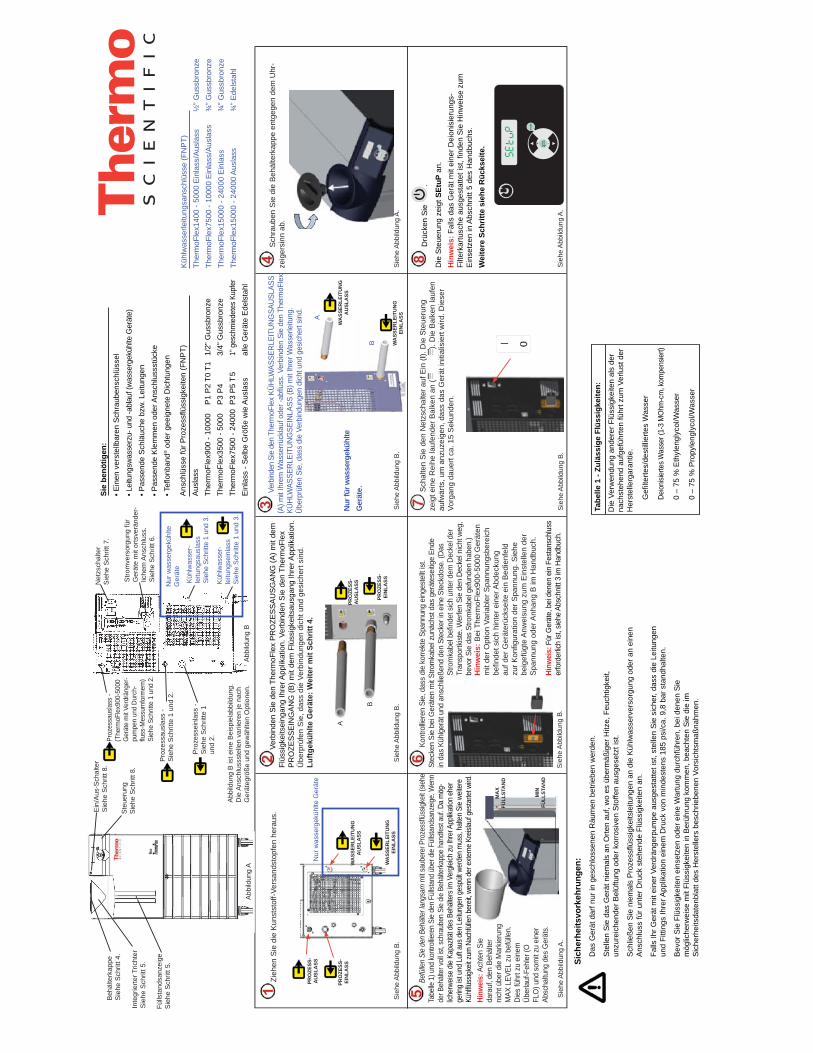
Bef
üllen
Sie
den
Behä
lter l
angs
am m
it sau
bere
r Pro
zess
flüss
igkeit
(sieh
e Ta
belle
1) u
nd ko
ntro
lliere
n Si
e de
n Fü
llsta
nd ü
ber d
ie Fü
llsta
ndsa
nzeig
e. W
enn
der B
ehält
er vo
ll ist,
schr
aube
n Si
e die
Beh
älter
kapp
e ha
ndfe
st au
f. Da
mög
-lic
herw
eise
die K
apaz
ität d
es B
ehält
ers i
m V
ergle
ich zu
Ihre
r App
likat
ion e
her
gerin
g ist
und
Luf
t aus
den
Leit
unge
n ge
spült
wer
den
mus
s, ha
lten
Sie
weite
re
Kühlfl
üssig
keit z
um N
achf
üllen
ber
eit, w
enn
der e
xtern
e Kr
eislau
f ges
tarte
t wird
.
Drü
cken
Sie
.
Die
Ste
ueru
ng z
eigt
SEt
uP a
n.
Hin
wei
s: F
alls
das
Ger
ät m
it ei
ner D
eion
isie
rung
s-Fi
lterk
artu
sche
aus
gest
atte
t ist
, find
en S
ie H
inw
eise
zum
E
inse
tzen
in A
bsch
nitt
5 de
s H
andb
uchs
.W
eite
re S
chrit
te s
iehe
Rüc
ksei
te.
Zieh
en S
ie d
ie K
unst
stof
f-Ver
sand
stop
fen
hera
us.
Pro
zess
ausl
ass
- S
iehe
Sch
ritte
1 u
nd 2
.
Proz
essa
usla
ss -
(The
rmoF
lex9
00-5
000
Ger
äte
mit
Verd
räng
er-
pum
pen
und
Durc
h-flu
ss-M
essu
mfo
rmer
n)
Sieh
e Sc
hritt
e 1
und
2.
Net
zsch
alte
r S
iehe
Sch
ritt 7
.
Stro
mve
rsor
gung
für
Ger
äte
mit
orts
verä
nder
-lic
hem
Ans
chlu
ss.
Sie
he S
chrit
t 6.
Pro
zess
einl
ass
-S
iehe
Sch
ritte
1
und
2.
Abb
ildun
g B
ist e
ine
Bei
spie
labb
ildun
g.
Die
Ans
chlu
ssst
elle
n va
riier
en je
nac
h G
erät
egrö
ße u
nd g
ewäh
lten
Opt
ione
n.
Sch
raub
en S
ie d
ie B
ehäl
terk
appe
ent
gege
n de
m U
hr-
zeig
ersi
nn a
b.
Kon
trollie
ren
Sie,
das
s di
e ko
rrekt
e Sp
annu
ng e
inge
stel
lt ist
. St
ecke
n Si
e be
i Ger
äten
mit
Stro
mka
bel z
unäc
hst d
as g
erät
esei
tige
Ende
in
das
Küh
lger
ät u
nd a
nsch
ließe
nd d
en S
teck
er in
ein
e St
eckd
ose.
(Das
St
rom
kabe
l befi
ndet
sich
unt
er d
em D
ecke
l der
Tr
ansp
ortk
iste.
Wer
fen
Sie
den
Dec
kel n
icht w
eg,
bevo
r Sie
das
Stro
mka
bel g
efun
den
habe
n.)
Verb
inden
Sie
den
Ther
moF
lex
KÜH
LWAS
SER
LEIT
UN
GSA
USL
ASS
(A) m
it Ih
rem
Was
serrü
ckla
uf o
der -
abflu
ss. V
erbi
nden
Sie
den
The
rmoF
lex
KÜH
LWAS
SER
LEIT
UN
GSE
INLA
SS (B
) mit
Ihre
r Was
serle
itung
. Ü
berp
rüfe
n Si
e, d
ass
die
Verb
indu
ngen
dic
ht u
nd g
esic
hert
sind
.
P (
Küh
lwas
ser-
le
itung
sein
lass
Sie
he S
chrit
te 1
und
3.
Küh
lwas
ser-
le
itung
saus
lass
Sieh
e Sc
hritt
e 1
und
3.
Nur
was
serg
eküh
lte
Ger
äte
Sie
benö
tigen
:• E
inen
ver
stel
lbar
en S
chra
uben
schl
üsse
l• L
eitu
ngsw
asse
rzu-
und
-abl
auf (
was
serg
eküh
lte G
erät
e)• P
asse
nde
Sch
läuc
he b
zw. L
eitu
ngen
• Pas
send
e K
lem
men
ode
r Ans
chlu
ssst
ücke
• Tefl
onba
nd® o
der g
eeig
nete
Dic
htun
gen
Nur
was
serg
eküh
lte G
erät
e
Sich
erhe
itsvo
rkeh
rung
en:
Das
Ger
ät d
arf n
ur in
ges
chlo
ssen
en R
äum
en b
etrie
ben
wer
den.
Ste
llen
Sie
das
Ger
ät n
iem
als
an O
rten
auf,
wo
es ü
berm
äßig
er H
itze,
Feu
chtig
keit,
un
zure
iche
nder
Bel
üftu
ng o
der k
orro
sive
n S
toffe
n au
sges
etzt
ist.
Sch
ließe
n S
ie n
iem
als
Pro
zess
flüss
igke
itsle
itung
en a
n di
e K
ühlw
asse
rver
sorg
ung
oder
an
eine
n A
nsch
luss
für u
nter
Dru
ck s
tehe
nde
Flüs
sigk
eite
n an
.
Falls
Ihr G
erät
mit
eine
r Ver
drän
gerp
umpe
aus
gest
atte
t ist
, ste
llen
Sie
sic
her,
dass
die
Lei
tung
en
und
Fitti
ngs
Ihre
r App
likat
ion
eine
m D
ruck
von
min
dest
ens
185
psi/c
a. 9
,8 b
ar s
tand
halte
n.
Bev
or S
ie F
lüss
igke
iten
eins
etze
n od
er e
ine
War
tung
dur
chfü
hren
, bei
den
en S
ie
mög
liche
rwei
se m
it Fl
üssi
gkei
ten
in B
erüh
rung
kom
men
, bea
chte
n S
ie d
ie im
S
iche
rhei
tsda
tenb
latt
des
Her
stel
lers
bes
chrie
bene
n Vo
rsic
htsm
aßna
hmen
.
Abb
ildun
g B
Nur f
ür w
asse
rgek
ühlte
G
erät
e .
Sie
he A
bbild
ung
A.
Sie
he A
bbild
ung
B.
Sie
he A
bbild
ung
B.
Sie
he A
bbild
ung
B.
Sie
he A
bbild
ung
B.
Sie
he A
bbild
ung
B.
Sie
he A
bbild
ung
A.
Sie
he A
bbild
ung
A.
Verb
inde
n S
ie d
en T
herm
oFle
x P
RO
ZES
SA
US
GA
NG
(A) m
it de
m
Flüs
sigk
eits
eing
ang
Ihre
r App
likat
ion.
Ver
bind
en S
ie d
en T
herm
oFle
x P
RO
ZES
SE
ING
AN
G (B
) mit
dem
Flü
ssig
keits
ausg
ang
Ihre
r App
likat
ion.
Ü
berp
rüfe
n S
ie, d
ass
die
Verb
indu
ngen
dic
ht u
nd g
esic
hert
sind
. Lu
ftgek
ühlte
Ger
äte:
Wei
ter m
it Sc
hritt
4.
Sch
alte
n S
ie d
en N
etzs
chal
ter a
uf E
in (I
). D
ie S
teue
rung
ze
igt e
ine
Rei
he la
ufen
der B
alke
n an
().
Die
Bal
ken
lauf
en
aufw
ärts
, um
anz
uzei
gen,
das
s da
s G
erät
initi
alis
iert
wird
. Die
ser
Vorg
ang
daue
rt ca
. 15
Sek
unde
n.
B
A
B
A
Ste
ueru
ng
Sie
he S
chrit
t 8.
Ein
/Aus
-Sch
alte
rS
iehe
Sch
ritt 8
.
Inte
grie
rter T
richt
erS
iehe
Sch
ritt 5
.
Fülls
tand
sanz
eige
Sie
he S
chrit
t 5.
Abb
ildun
g A
Beh
älte
rkap
peS
iehe
Sch
ritt 4
.
PRO
ZESS
-EI
NLA
SS
PRO
ZESS
-A
USL
ASS
WA
SSER
LEIT
UN
GEI
NLA
SS
WA
SSER
LEIT
UN
GA
USL
ASS
WA
SSER
LEIT
UN
GEI
NLA
SS
WA
SSER
LEIT
UN
GA
USL
ASS
PRO
ZESS
-EI
NLA
SS
PRO
ZESS
-A
USL
ASS
Hinw
eis:
Ach
ten
Sie
dara
uf, d
en B
ehäl
ter
nich
t übe
r die
Mar
kieru
ng
MAX
LEV
EL z
u be
fülle
n.
Dies
führ
t zu
eine
m
Über
lauf
-Feh
ler (
O
FLO
) und
som
it zu
ein
er
Absc
haltu
ng d
es G
erät
s.
Ans
chlü
sse
für P
roze
ssflü
ssig
keite
n (F
NP
T)A
usla
ss
Ther
moF
lex9
00 -
1000
0 P
1 P
2 T0
T1
1/2"
Gus
sbro
nze
Ther
moF
lex3
500
- 500
0 P
3 P
4 3/
4" G
ussb
ronz
eTh
erm
oFle
x750
0 - 2
4000
P3
P5
T 5
1" g
esch
mie
dete
s Ku
pfer
Ein
lass
- S
elbe
Grö
ße w
ie A
usla
ss
alle
Ger
äte
Ede
lsta
hl
Küh
lwas
serle
itung
sans
chlü
sse
(FN
PT)
Ther
moF
lex1
400
- 500
0 E
inla
ss/A
usla
ss
½” G
ussb
ronz
e Th
erm
oFle
x750
0 - 1
0000
Ein
lass
/Aus
lass
¾
” Gus
sbro
nze
Ther
moF
lex1
5000
- 24
000
Ein
lass
¾
” Gus
sbro
nze
Ther
moF
lex1
5000
- 24
000
Aus
lass
¾
” Ede
lsta
hl
Hin
wei
s: B
ei T
herm
oFle
x900
-500
0 G
erät
en
mit
der O
ptio
n Va
riabl
er S
pann
ungs
bere
ich
befin
det s
ich
hint
er e
iner
Abd
ecku
ng
auf d
er G
erät
erüc
ksei
te e
in B
edie
nfel
d zu
r Kon
figur
atio
n de
r Spa
nnun
g. S
iehe
be
igef
ügte
Anw
eisu
ng z
um E
inst
elle
n de
r S
pann
ung
oder
Anh
ang
B im
Han
dbuc
h.
Hinw
eis:
Für
Ger
äte,
bei
den
en e
in F
esta
nsch
luss
er
ford
erlic
h ist
, sie
he A
bsch
nitt
3 im
Han
dbuc
h.
Die
Ver
wen
dung
and
erer
Flü
ssig
keite
n al
s de
r na
chst
ehen
d au
fgef
ührte
n fü
hrt z
um V
erlu
st d
er
Her
stel
lerg
aran
tie.
G
efilte
rtes/
dest
illie
rtes
Was
ser
De
ionisi
erte
s Was
ser (
1-3
MO
hm-c
m, k
ompe
nsier
t)
0
– 75
% E
thyl
engl
ycol
/Was
ser
0
– 75
% P
ropy
leng
lyco
l/Was
ser
Tabe
lle 1
- Zu
läss
ige
Flüs
sigk
eite
n:

• Dru
k op
• H
et d
ispl
ay z
al k
nipp
eren
tuss
en H
i t e
n42
• Geb
ruik,
indi
en g
ewen
st,
om d
e w
aard
e aa
n te
pas
sen
• Dru
k op
g om n
aar h
et v
olge
nde
disp
lay
te g
aan
• Dru
k op
• H
et d
ispl
ay z
al k
nipp
eren
tuss
en L
o t e
n3
• Geb
ruik
, ind
ien
gew
enst
, om
de
waa
rde
aan
te p
asse
n
• Dru
k op
Met
Lo
t wor
dt d
e on
ders
te
alar
mlim
iet v
oor d
e te
mpe
ratu
ur
van
de v
loei
stof
inge
stel
d.
Ber
eik:
+3°
C to
t +42
°CFa
brie
ksst
anda
ard:
3°C
• Dru
k op
• H
et d
isplay
zal k
nippe
ren
tuss
en H
i P1
en d
e sta
ndaa
rdwa
arde
• Geb
ruik,
indie
n ge
wens
t, om
de
waar
de a
an te
pas
sen
• Dru
k op
g
Met
Hi P
1 w
ordt
de
bove
nste
al
arm
limie
t voo
r dru
kafv
oer v
an
de p
omp
inge
stel
d.B
erei
k: V
ersc
hilt
per p
omp
Fabr
ieks
stan
daar
d: V
ersc
hilt
per
pom
p• H
et d
ispl
ay z
al k
nipp
eren
tuss
en d
ELAY
en
0
• Geb
ruik
, ind
ien
gew
enst
, om
de
waa
rde
aan
te p
asse
n
• Dru
k op
dELA
Y is
de
tijds
duur
dat
de
pom
p de
H
i P1
Ala
rmlim
iet k
an o
vers
chrij
den
voor
hij
uits
chak
elt.
Ber
eik:
Ver
schi
lt pe
r pom
pFa
brie
ksst
anda
ard:
0 s
econ
den
• Dru
k op
• H
et d
ispl
ay z
al k
nipp
eren
tuss
en L
o P1
en
de
stan
daar
dwaa
rde
• Geb
ruik
, ind
ien
gew
enst
, om
de
stan
daar
dwaa
rde
aan
te p
asse
n
• Dru
k op
Met
Lo
P1 w
ordt
de
onde
rste
al
arm
limie
t voo
r dru
kafv
oer v
an
de p
omp
inge
stel
d.B
erei
k: V
ersc
hilt
per p
omp
Fabr
ieks
stan
daar
d: V
ersc
hilt
per p
omp
dELA
Y is
de
tijds
duur
dat
de
pom
pde
Lo
P1 k
an o
vers
chrij
den
Ala
rmlim
iet v
oord
at h
et
uits
chak
elen
pla
atsv
indt
.
Ber
eik:
0 to
t 30
seco
nden
Fabr
ieks
stan
daar
d: 1
0 se
cond
en
• Het
dis
play
zal
kni
pper
en tu
ssen
dEL
AY e
n10
• Geb
ruik
, ind
ien
gew
enst
, om
de
waa
rde
aan
te
pass
en
• Dru
k op
• Dru
k op
• H
et d
ispl
ay z
al k
nipp
eren
tuss
en A
Lren
fLt
• Dru
k, in
dien
gew
enst
, op
om
indC
wee
r te
geve
n
• Dru
k op
g
Zet h
et h
oorb
are
alar
m v
an d
e un
it aa
n of
uit.
Ber
eik:
aan
of U
ITFa
brie
ksst
anda
ard:
aan
• Dru
k op
• H
et d
ispl
ay z
al k
nipp
eren
tuss
en S
ound
enaa
n
• Dru
k, in
dien
gew
enst
, op
om
OFF
wee
r te
gev
en
• Dru
k op
• Dru
k op
• H
et d
ispl
ay z
al k
nipp
eren
tuss
en S
tArt
enU
IT
• Dru
k, in
dien
gew
enst
, op
om
aan
wee
r te
geve
n
• Dru
k op
StA
Rt s
chak
elt d
e au
to re
star
t in
en u
it.
Ber
eik:
aan
of U
ITFa
brie
ksst
anda
ard:
UIT
• Dru
k op
• H
et d
ispl
ay z
al k
nipp
eren
tuss
en C
ArE
enL1
• Geb
ruik
, ind
ien
gew
enst
, om
het
dis
play
te
wijz
igen
in u
it, L
2 of
L3
• Dru
k op
CA
rEw
ordt
geb
ruik
t om
de
freq
uent
ie
van
de h
erin
nerin
g vo
or h
et p
reve
ntie
f sc
hoon
mak
en v
an d
e lu
cht-
en
vloe
isto
ffi lte
rs v
an d
e un
it in
te s
telle
n.B
erei
k: u
it, L
1 - 1
000
uur,
L2 -
2000
uur
, L3
-300
0 uu
rFa
brie
ksst
anda
ard:
L1
• D
ruk
op
om
alle
inst
ellin
gen
op te
sla
an
D
e un
it za
l aut
omat
isch
sta
rten
.•
Dru
k op
o
m a
lle w
ijzig
inge
n on
geda
an te
m
aken
en
de s
tand
aard
fabr
ieks
waa
rden
te h
erst
elle
n.
Het
dis
play
zal
bla
nco
zijn
.
D
ruk
op
om
de
proc
edur
e op
nieu
w te
sta
rten.
De
Setu
p-pr
oced
ure
is n
u vo
ltooi
d.
Als
de
unit
star
t, za
l de
best
urin
g de
tem
pera
tuur
va
n de
pro
cesv
loei
stof
wee
rgev
en.
Indi
en g
ewen
st k
unt u
het
set
poin
t van
de
unit
wijz
igen
/con
trol
eren
doo
r op
te d
rukk
en.
SP w
ordt
geb
ruik
t om
het
set
poin
t aa
n te
pas
sen.
Ber
eik:
+5°
C to
t +40
°CFa
brie
ksst
anda
ard:
+20
°C• H
et d
ispl
ay z
al k
nipp
eren
tuss
en S
P en
20• I
ndie
n ge
wen
st k
unt u
ge
brui
ken
om d
e in
stel
ling
te w
ijzig
en
• Dru
k op
o
m h
et n
ieuw
e se
tpoi
nt o
p te
sla
an e
n na
ar d
e te
mpe
ratu
urw
eerg
ave
teru
g te
ker
en
Raa
dple
eg, i
ndie
n va
n to
epas
sing
, de
kade
rs re
chts
voo
r het
inst
elle
n va
n de
opt
ies.
Raa
dple
eg v
oor u
nits
m
et A
nalo
og I/
O (A
CO
M) d
e ad
ditio
nele
qui
ck s
tart
die
bij
de u
nit i
s ge
leve
rd.
Qui
ck S
tart
- A
lleen
geb
ruik
t voo
r het
initi
eel o
psta
rten
- vo
er d
e st
appe
n 9
tot 2
0 ui
t voo
r alle
uni
ts.
**fL
t = fa
ult (
uits
chak
elen
)**
indC
= in
dica
te (i
n w
erki
ng b
lijve
n)
Met
Hi t
kan
de
Ala
rmlim
iet v
oor
hoge
tem
pera
tuur
voo
r de
vloe
isto
f w
orde
n in
gest
eld.
Ber
eik:
+3°
C to
t +42
°CFa
brie
ksst
anda
ard:
+42
°C• D
ruk
op
• Het
dis
play
zal
kni
pper
en tu
ssen
Uni
tSen
°C• G
ebru
ik, in
dien
gew
enst
, o
m d
e sc
haal
in °F
te v
eran
dere
n
• Dru
k op
g
om n
aar h
et v
olge
nde
disp
lay
te g
aan
• Doe
het
zelfd
e vo
or d
e sc
hale
n vo
or F
low
en
druk
• Dru
k op
• H
et d
ispl
ay z
al k
nipp
eren
tuss
en u
id e
n1
• Ind
ien
gew
enst
kun
t u
gebr
uike
n om
de
inst
ellin
g te
wijz
igen
• Dru
k op
jg
Met
HiF
LO w
ordt
de
bove
nste
al
arm
limie
t voo
r de
fl ow
inge
stel
d.
Ber
eik:
Ver
schi
lt pe
r pom
pFa
brie
ksst
anda
ard:
Ver
schi
lt pe
r po
mp
• Dru
k op
• H
et d
ispl
ay z
al k
nipp
eren
tuss
en H
iFLO
en d
e st
anda
ardw
aard
e• G
ebru
ik, in
dien
gew
enst
, om
de
waar
de a
an te
pas
sen
• Dru
k op
g
• Dru
k op
• H
et d
ispl
ay z
al k
nipp
eren
tuss
en L
oFLO
en d
e st
anda
ardw
aard
e• G
ebru
ik, in
dien
gewe
nst,
om d
e wa
arde
aan
te p
asse
n
• Dru
k op
g
Met
LoF
LO w
ordt
de
onde
rste
al
arm
limie
t voo
r de
fl ow
inge
stel
d.
Ber
eik:
Ver
schi
lt pe
r pom
pFa
brie
ksst
anda
ard:
Ver
schi
lt pe
r po
mp
• Dru
k op
• H
et d
ispl
ay z
al k
nipp
eren
tuss
en S
toP
en1
• Ind
ien
gew
enst
kun
t u
gebr
uike
n om
de
inst
ellin
g te
wijz
igen
• Dru
k op
jg
StoP
wor
dt g
ebru
ikt o
m h
et a
anta
l st
opbi
ts a
an te
gev
en.
Ber
eik:
2 o
f 1Fa
brie
ksst
anda
ard:
1
u id
(uni
t id)
wor
dt a
lleen
in R
S485
ge
brui
kt. I
dent
ifi ce
ert a
ppar
aten
die
op
de
RS4
85-p
oort
zijn
aan
gesl
oten
.
Ber
eik:
1 to
t 99
Fabr
ieks
stan
daar
d: 1
• Dru
k op
• H
et d
ispl
ay z
al k
nipp
eren
tuss
en S
Eren
UIT
• Ind
ien
gew
enst
kun
t u
gebr
uike
n om
de
mod
us
te w
ijzig
en
• Dru
k op
SEr w
ordt
geb
ruik
t voo
r het
in
scha
kele
n/ui
tsch
akel
en e
n co
nfi g
urer
en v
an d
e se
riële
-co
mm
unic
atie
mod
usB
erei
k: u
it, rS
232,
rS48
5Fa
brie
ksst
anda
ard:
uit
• Dru
k op
• H
et d
ispl
ay z
al k
nipp
eren
tuss
en B
Aud
en96
00• I
ndie
n ge
wen
st k
unt u
ge
brui
ken
om d
e sn
elhe
id te
wijz
igen
• Dru
k op
jg
BA
ud w
ordt
geb
ruik
t om
de
baud
rate
(sne
lhei
d) v
oor s
erië
le
com
mun
icat
ie te
kie
zen.
Ber
eik:
960
0, 4
800,
240
0, 1
200,
60
0 of
300
bits
per
sec
onde
.Fa
brie
ksst
anda
ard:
960
0
• Dru
k op
• H
et d
ispl
ay z
al k
nipp
eren
tuss
en d
AtA
en
8
• Dru
k op
y
dAtA
wor
dt g
ebru
ikt o
m h
et
aant
al b
its w
eer t
e ge
ven.
Dis
play
: 8
• Dru
k op
• H
et d
ispl
ay z
al k
nipp
eren
tuss
en P
Ar e
nge
en• I
ndie
n ge
wen
st k
unt u
ge
brui
ken
om d
e in
stel
ling
te w
ijzig
en
• Dru
k op
jg
PAr w
ordt
geb
ruik
t als
een
mid
del
om o
p co
mm
unic
atie
fout
en te
co
ntro
lere
n.B
erei
k: e
ven,
one
ven
of g
een
Fabr
ieks
stan
daar
d: g
een
Opt
ie -
Volu
mes
troo
mom
zette
r - S
tapp
en B
en
C
Als
uw
uni
t gee
n se
riële
com
-m
unic
atie
hee
ft, z
ie s
tap
20.
Zie
stap
20.
Opt
ie -
Serië
le c
omm
unic
atie
(DC
OM
) - S
tapp
en D
tot I
Uni
tS z
ijn d
e sc
hale
n vo
or
tem
pera
tuur
, fl o
w v
an d
e vl
oeis
tof
(opt
ione
el) e
n dr
uk.
Scha
len:
°C
/°F
GPM
/LPM
PS
I/Bar
/KPA
SFa
brie
ksst
anda
ard:
°C, G
allo
ns, P
SI
• Dru
k op
• Het
dis
play
zal
kni
pper
en tu
ssen
HZ
en60
• Geb
ruik
, ind
ien
nodi
g,
om d
e fre
quen
tie te
w
ijzig
en
• Dru
k op
A
ls u
w u
nit g
een
volu
mes
troo
m-
omze
tter o
f ser
iële
com
mun
icat
ie
heef
t, zi
e st
ap 2
0.
Opt
ie -
Uni
vers
ele
span
ning
- St
ap A
HZ
wor
dt g
ebru
ikt o
m d
e bi
nnen
kom
ende
fr
eque
ntie
te id
entifi
cer
en v
oor u
nits
met
un
iver
sele
spa
nnin
g. D
e ge
sele
ctee
rde
freq
uent
ie
past
aut
omat
isch
de
vast
e st
anda
ardi
nste
lling
va
n de
fabr
ikan
t voo
r hog
e dr
uk a
an.
Ber
eik:
50
of 6
0 H
z St
anda
ard:
60
Hz
II
Dru
k op
om
naa
r de
setu
ppro
cedu
re te
gaa
n.
Let o
p: S
omm
ige
bere
iken/
stan
daar
dwaa
rden
zij
n af
hank
elijk
van
de
pom
p, z
ie h
oofd
stuk
4 in
de
hand
leid
ing.
Als
een
Setu
p-st
ap e
enm
aal is
vol
tooi
d,
wat b
etek
ent d
at u
de
toet
s ee
n tw
eede
maa
l he
bt in
gedr
ukt,
kunt
u d
e st
ap n
iet m
eer h
erha
len
om c
orre
ctie
s aa
n te
bre
ngen
. U k
unt w
ijzig
inge
n do
orvo
eren
nad
at d
e un
it is
gest
art.
LET
OP
Dez
e fu
nctie
is a
lleen
act
ief a
ls d
e un
it ge
confi
gur
eerd
is o
m u
it te
sch
akel
en, z
ie s
tap
16.
LET
OP
Dez
e fu
nctie
is a
lleen
act
ief a
ls d
e un
it ge
confi
gur
eerd
is o
m u
it te
sch
akel
en,
zie
stap
16.
ALr
con
fi gur
eert
de
reac
tie v
an
de u
nit o
p al
arm
limie
ten
voor
te
mpe
ratu
ur, d
ruk
en fl
ow (o
ptio
neel
) - o
fwel
uits
chak
elen
(fLt
) of i
n w
erki
ng
blijv
en (i
ndC
). Zi
e H
oofd
stuk
4 v
an d
e ha
ndle
idin
g vo
or m
eer i
nfor
mat
ie.
Ber
eik:
fLt*
of i
ndC
**Fa
brie
ksst
anda
ard:
fLt

MIN
IMU
MN
IVEA
U
MA
XIM
UM
NIV
EAU
Rem
plis
sez
lent
emen
t le
rése
rvoi
r ave
c du
liqu
ide
de tr
aite
men
t ap
prop
rié (v
oir l
e Ta
blea
u 1)
en
utili
sant
le re
gard
pou
r con
trôle
r fac
ilem
ent
le n
ivea
u de
liqu
ide.
Une
fois
le ré
serv
oir r
empl
i, re
met
tez
le b
ouch
on e
n le
se
rran
t à la
mai
n. L
a ca
paci
té d
u ré
serv
oir p
ouva
nt ê
tre ré
duite
par
rapp
ort
à l’a
pplic
atio
n, e
t l’a
ir de
vant
être
pur
gé d
es c
ondu
ites,
gar
dez
du li
quid
e su
pplé
men
taire
à p
orté
e de
la m
ain
pour
faire
le n
ivea
u du
sys
tèm
e un
e fo
is la
circ
ulat
ion
exte
rne
dém
arré
e.
App
uyez
sur
.
Le c
ontrô
leur
affi
che
SEtu
P.
Rem
arqu
e : S
i l’a
ppar
eil e
st é
quip
é d’
une
carto
uche
de fil
tre d
e dé
ioni
satio
n, c
onsu
ltez
le m
anue
l, S
ectio
n 5,
pou
r l’in
stal
latio
n.
Voir
au d
os le
s ét
apes
sup
plém
enta
ires.
Ret
irer l
es b
ouch
ons
d’ex
pédi
tion
en p
last
ique
.
Sor
tie F
luid
e du
The
rmo-
Flex
ver
s ap
plic
atio
nVo
ir le
s ét
apes
1 e
t 2.
Éva
cuat
ion
de tr
ai-
tem
ent -
(app
arei
ls
Ther
moF
lex9
00-
5000
ave
c po
mpe
s P
D e
t tra
nsdu
cteu
rs
de d
ébit)
Voi
r les
ét
apes
1 e
t 2.
Pro
tect
ion
de c
ircui
t Vo
ir l’é
tape
7.
Arr
ivée
éle
ctriq
ue p
our
les
appa
reils
san
s câ
blag
e m
atér
iel
Voir
l’éta
pe 6
.
Ret
our F
luid
e de
l’ap
plic
a-tio
n ve
rs le
The
rmoF
lex
Voir
les
étap
es 1
et 2
.La
Fig
ure
B e
st re
prés
enta
tive.
Le
s em
plac
emen
ts v
arie
nt e
n fo
nctio
n de
la ta
ille
de l’
appa
reil
et d
es o
ptio
ns c
hois
ies.
Dép
osez
le ré
serv
oir e
n le
dév
issa
nt d
ans
le s
ens
in-
vers
e au
x ai
guill
es d
’une
mon
tre.
Vér
ifiez
que
la te
nsio
n es
t cor
rect
e. P
our l
es a
ppar
eils
four
nis
avec
un
cor
don
d’al
imen
tatio
n, in
sére
z l’e
xtré
mité
fem
elle
de
ce d
erni
er d
ans
le re
froid
isse
ur, e
t l’e
xtré
mité
mâl
e da
ns la
pris
e él
ectri
que.
(Le
cord
on
d’al
imen
tatio
n se
trou
ve s
ous
le c
ouve
rcle
de
la c
aiss
e d’
expé
ditio
n. N
e je
tez
pas
le
couv
erte
ava
nt d
’avo
ir lo
calis
é le
cor
don.
Rac
cord
ez le
The
rmoF
lex
vers
ÉVA
CU
ATIO
N D
U S
ITE
(A)
à l’é
vacu
atio
n d’
eau
de v
otre
site
. Rac
cord
ez le
The
rmoF
lex
de
l’AR
RIV
ÉE
DU
SIT
E (B
) sur
l’ar
rivée
d’e
au d
e vo
tre s
ite. V
érifi
ez q
ue
les
racc
ords
son
t éta
nche
s et
sûr
s.
Arr
ivée
du
si
teVo
ir le
s ét
apes
1 e
t 3.
Éva
cuat
ion
du s
iteVo
ir le
s ét
apes
1 e
t 3.
App
arei
ls re
froid
is p
ar
eau
seul
emen
t.
Mat
érie
l néc
essa
ire p
our c
omm
erce
r :• U
ne c
lé à
mol
ette
• Alim
enta
tion
et é
vacu
atio
n d’
eau
du s
ite (p
our l
es a
ppar
eils
re
froid
is p
ar e
au)
• Tuy
au e
t acc
esso
ires
de p
lom
berie
app
ropr
iés
• Pin
ces
ou ty
pe d
e ra
ccor
d de
dim
ensi
on a
ppro
prié
e• R
uban
adh
ésif
au T
eflon
® o
u pr
odui
t éta
nché
ifian
t app
ropr
ié
App
arei
ls re
froid
is p
ar e
au
seul
emen
t.
Préc
autio
ns d
e sé
curit
é :
L’ap
pare
il es
t con
çu p
our f
onct
ionn
er e
xclu
sive
men
t à l’
inté
rieur
.
Ne
jam
ais
l’exp
oser
à u
ne c
hale
ur o
u un
e hu
mid
ité e
xces
sive
, une
ve
ntila
tion
inad
équa
te o
u à
des
mat
ière
s co
rros
ives
.
Ne
jam
ais
racc
orde
r les
con
duite
s de
liqu
ide
de tr
aite
men
t à l’
arriv
ée
d’ea
u de
vot
re s
ite o
u à
une
sour
ce d
e liq
uide
sou
s pr
essi
on.
Si v
otre
app
arei
l est
équ
ipé
d’un
e po
mpe
à d
épla
cem
ent p
ositi
f, vé
rifiez
qu
e le
s co
ndui
tes
de p
lom
berie
et l
es ra
ccor
ds d
e vo
tre a
pplic
atio
n on
t la
capa
cité
de
supp
orte
r au
moi
ns 1
85 p
si.
Avan
t d’u
tilis
er u
n liq
uide
que
lcon
que
ou d
’effe
ctue
r des
trav
aux
d’en
tretie
n su
scep
tible
s d’
entra
îner
un
cont
act a
vec
le li
quid
e, c
onsu
ltez
les
reco
mm
anda
tions
de
sant
é-sé
curit
é du
fabr
ican
t.
Figu
re B
Uniq
uem
ent p
our l
es
appa
reils
refro
idis
par
eau
.
Voir
la F
igur
e A
.
Voir
la F
igur
e B
.Vo
ir la
Fig
ure
B.
Voir
la F
igur
e B
.
Voir
la F
igur
e B
.Vo
ir la
Fig
ure
B.
Voir
la F
igur
e A
.
Voir
la F
igur
e A
.
Rac
cord
ez l’
appl
icat
ion
: Sor
tie F
luid
e du
The
rmoF
lex
(A)
à l’a
rriv
ée d
e liq
uide
de
votre
app
licat
ion,
et l
e R
etou
r Flu
ide
de
l’app
licat
ion
du T
herm
oFle
x (B
) à l’
évac
uatio
n de
liqu
ide
de v
otre
ap
plic
atio
n. V
érifi
ez q
ue le
s ra
ccor
ds s
ont é
tanc
hes
et s
ûrs.
Pou
r les
ap
pare
ils re
froi
dis
par a
ir, p
asse
z à
l’éta
pe 4
.
Pla
cez
la p
rote
ctio
n de
circ
uit e
n po
sitio
n (I)
. L’a
ffich
age
du
cont
rôle
ur in
diqu
e un
e sé
rie d
e ba
rres
de
défil
emen
t ().
Les
barr
es d
éfile
nt v
ers
le h
aut,
indi
quan
t l’in
itial
isat
ion
de l’
appa
-re
il ; c
ette
opé
ratio
n pr
end
envi
ron
15 s
econ
des.
B
A
B
A
Con
trôle
ur
Voir
l’éta
pe 8
.
Bou
ton
d’al
imen
tatio
nVo
ir l’é
tape
8.
Ent
onno
ir in
tégr
éV o
ir l’é
tape
5.
Indi
cate
ur d
e ni
veau
Voir
l’éta
pe 5
.
Figu
re A
Bou
chon
de
rése
rvoi
rVo
ir l’é
tape
4.
Ret
our F
luid
e de
l’ap
plic
a-tio
n ve
rs le
The
rmoF
lex
Sort
ie F
luid
e du
The
rmo-
Flex
ver
s ap
plic
atio
n
AR
RIV
ÉE D
U S
ITE
ÉVA
CU
ATIO
N D
U S
ITE
AR
RIV
ÉE D
U S
ITE
ÉVA
CU
ATIO
N D
U S
ITE
Ret
our F
luid
e de
l’ap
plic
a-tio
n ve
rs le
The
rmoF
lex
Rem
arqu
e : V
eille
z à
ne p
as re
mpl
ir le
ré
serv
oir a
u-de
ssus
de
la li
gne
MAX
LEV
EL
(NIV
EAU
MAX
I). C
ela
entra
îne
une
erre
ur
de d
ébor
dem
ent d
e l’a
ppar
eil (
O F
LO) q
ui
peut
pro
voqu
er s
on a
rrêt.
Rac
cord
emen
ts d
u flu
ide
de tr
aite
men
t (FN
PT)
Éva
cuat
ion
Ther
moF
lex9
00 -
1000
0 P
1 P
2 T0
T1
font
e de
bro
nze
1/2"
Ther
moF
lex3
500
- 500
0 P
3 P
4 fo
nte
de b
ronz
e 3/
4"Th
erm
oFle
x750
0 - 2
4000
P
3 P
5 T
5 cu
ivre
forg
é 1"
Arriv
ée -
taille
iden
tique
à l’é
vacu
atio
n to
us a
ppar
eils
en a
cier
Rem
arqu
e : L
es a
ppar
eils
The
rmoF
lex9
00-5
000
équi
pés
de l’o
ptio
n Te
nsio
n va
riabl
e ou
Ten
sion
gl
obal
e po
ssèd
ent u
n pa
nnea
u de
config
urat
ion
de la
tens
ion
situ
é de
rrièr
e un
e tra
ppe
d’ac
cès
à l’a
rrièr
e de
l’app
arei
l. C
onsu
ltez
la fi
che
d’in
stru
ctio
ns re
lativ
e à
la te
nsio
n liv
rée
avec
l’a
ppar
eil,
ou l’a
nnex
e B
du m
anue
l.R
emar
que
: Pou
r les
app
arei
ls e
xige
ant u
n câ
blag
e m
atér
iel,
cons
ulte
z la
Sec
tion
3 du
m
anue
l.
L’utili
satio
n d’
un q
uelco
nque
liqui
de n
e fig
uran
t pas
da
ns la
liste
ci-d
esso
us a
nnul
e la
gar
antie
du
fabr
icant
.
E
au fi
ltrée
/mon
o di
still
ée
E
au d
éion
isée
(1 à
3 MΩ
-cm
, com
pens
ée)
É
thyl
ène
glyc
ol/e
au 0
à 7
5 %
P
ropy
lène
gly
col/e
au 0
à 7
5 %
Tabl
eau
1 - L
iqui
des
acce
ptab
les
:
Rac
cord
emen
ts à
l’ea
u du
site
(FN
PT)
Ther
moF
lex1
400
- 500
0 A
rriv
ée/é
vacu
atio
n fo
nte
de b
ronz
e ½
” Th
erm
oFle
x750
0 - 1
0000
Arr
ivée
/éva
cuat
ion
font
e de
bro
nze
¾”
Ther
moF
lex1
5000
- 24
000
Arr
ivée
font
e de
bro
nze
½”
Ther
moF
lex1
5000
- 24
000
évac
uatio
n fo
nte
de a
cier
inox
ydab
le ¾
”
Gril
le a
mov
ible
Sort
ie F
luid
e du
The
rmo-
Flex
ver
s ap
plic
atio
n

• App
uyez
sur
• L
’affi
chag
e cl
igno
te e
n al
tern
ant H
i t e
t42
• Au
beso
in, u
tilis
ez
pour
mod
ifi er
la v
aleu
r
• App
uyez
sur
po
ur p
asse
r à l’
affi c
hage
sui
vant
• App
uyez
sur
• L
’affi
chag
e cl
igno
te e
n al
tern
ant L
o t e
t3• A
u be
soin
, util
isez
po
ur m
odifi
er la
val
eur
• App
uyez
sur
Lo t
règl
e la
lim
ite d
’ala
rme
de b
asse
te
mpé
ratu
re d
u liq
uide
.Pl
age
: +3°
C à
+42
°CR
égla
ge d
’usi
ne p
ar d
éfau
t : 3
°C
• App
uyez
sur
• L
’affi
chag
e cl
igno
te e
n al
tern
ant H
i P1
et la
val
eur p
ar d
éfau
t
• Au
beso
in, u
tilis
ez
pour
mod
ifi er
la v
aleu
r
• App
uyez
sur
Hi P
1 rè
gle
la li
mite
d’a
larm
e de
dé
char
ge h
aute
pre
ssio
n de
la p
ompe
.Pl
age
: Var
ie e
n fo
nctio
n de
la p
ompe
Rég
lage
d’u
sine
par
déf
aut :
Var
ie e
n fo
nctio
n de
la p
ompe
• L’a
ffi ch
age
clig
note
en
alte
rnan
t dEL
AY e
t0
• Au
beso
in, u
tilis
ez
pour
mod
ifi er
la v
aleu
r
• App
uyez
sur
dELA
Y re
prés
ente
la d
urée
pen
dant
la
quel
le la
pom
pe p
eut d
épas
ser l
a va
leur
d’
alar
me
Hi P
1 av
ant l
’arr
êt.
Plag
e : V
arie
en
fonc
tion
de la
pom
peR
égla
ge d
’usi
ne p
ar d
éfau
t : 0
sec
onde
s
• App
uyez
sur
• L
’affi
chag
e cli
gnot
e en
alte
rnan
t Lo
P1 e
t la
vale
ur p
ar d
éfau
t
• Au
beso
in, u
tilis
ez
pour
aju
ster
la v
aleu
r par
déf
aut
• App
uyez
sur
Lo P
1 rè
gle
la li
mite
d’a
larm
e de
dé
char
ge b
asse
pre
ssio
n de
la p
ompe
.Pl
age
: Var
ie e
n fo
nctio
n de
la p
ompe
Rég
lage
d’u
sine
par
déf
aut :
Var
ie
en fo
nctio
n de
la p
ompe
dELA
Y re
prés
ente
la d
urée
pen
dant
la
quel
le la
pom
pe p
eut d
épas
ser l
a va
leur
Lo
P1
Lim
ite d
’ala
rme
avan
t arr
êt.
Plag
e : 0
à 3
0 se
cond
esR
égla
ge d
’usi
ne p
ar d
éfau
t :
10 s
econ
des
• L’a
ffi ch
age
clig
note
en
alte
rnan
t dEL
AY e
t10
• Au
beso
in, u
tilis
ez
pour
mod
ifi er
la v
aleu
r
• App
uyez
sur
• App
uyez
sur
• L
’affi
chag
e cl
igno
te e
n al
tern
ant A
Lret
fLt
• Au
beso
in, a
ppuy
ez s
ur
pou
r affi
cher
indC
• App
uyez
sur
y
Act
ive
ou d
ésac
tive
le s
igna
l so
nore
d’a
larm
e de
l’ap
pare
il.Pl
age
: on
(mar
che)
ou
OFF
(AR
RÊT
)R
égla
ge d
’usi
ne p
ar d
éfau
t : o
n (m
arch
e)
• App
uyez
sur
(m
• L’a
ffi ch
age
clig
note
en
alte
rnan
t Sou
ndet
on (m
arch
e)• A
u be
soin
, app
uyez
sur
p
our a
ffi ch
er O
FF(A
RR
ÊT)
• App
uyez
sur
• App
uyez
sur
• L
’affi
chag
e cl
igno
te e
n al
tern
ant S
tArt
etO
FF (A
RR
ÊT)
• Au
beso
in, a
ppuy
ez s
ur
pou
r affi
cher
on
(mar
che)
• App
uyez
sur
StA
rt a
ctiv
e/dé
sact
ive
le
redé
mar
rage
aut
omat
ique
.Pl
age
: on
(mar
che)
ou
OFF
(AR
RÊT
)R
égla
ge d
’usi
ne p
ar d
éfau
t : O
FF
(AR
RÊT
)
• App
uyez
sur
• L
’affi
chag
e cl
igno
te e
n al
tern
ant C
ArE
etL1
• Au
beso
in, u
tilise
z po
ur m
odifi e
r l’a
ffi ch
age
sur a
rrêt,
L2 o
u L3
• App
uyez
sur
CA
rEse
rt à
défi
nir
le ra
ppel
de
netto
yage
d’
entr
etie
n pr
éven
tif p
our l
es fi
ltres
à a
ir et
à li
quid
e de
l’ap
pare
il.
Plag
e : o
ff, L
1 - 1
000
heur
es,
L2 -
2000
heu
res,
L3
-300
0 he
ures
Rég
lage
d’u
sine
par
déf
aut :
L1
• Ap
puye
z su
r p
our e
nreg
istre
r tou
s le
s ré
glag
es
L’
appa
reil
dém
arre
aut
omat
ique
men
t.•
Appu
yez
sur
pou
r ign
orer
tout
es le
s m
odifi
catio
ns e
t rét
ablir
les
vale
urs
par d
éfau
t d’u
sine
.
L’af
fi che
est
vid
e.
A
ppuy
ez s
ur
pou
r rec
omm
ence
r la
proc
édur
e
La p
rocé
dure
de
confi
gur
atio
n es
t dés
orm
ais
term
inée
.
Au
dém
arra
ge d
e l’a
ppar
eil,
le c
ontr
ôleu
r affi
che
la
tem
péra
ture
du
liqui
de d
e l’a
pplic
atio
n.
Au
beso
in, v
ous
pouv
ez c
hang
er/v
érifi
er la
val
eur
de c
onsi
gne
de l’
appa
reil
en a
ppuy
ant s
ur
.
SP s
ert à
régl
er la
val
eur d
e co
nsig
ne.
Plag
e : +
5°C
à +
40°C
Rég
lage
d’u
sine
par
déf
aut :
+20
°C
• L’a
ffi ch
age
clig
note
en
alte
rnan
t SP
et20
• Au
beso
in, u
tilis
ez
pour
mod
ifi er
le ré
glag
e
• App
uyez
sur
p
our e
nreg
istre
r la
nouv
elle
val
eur d
e co
nsig
ne e
t rev
enir
à l’a
ffi ch
age
de la
tem
péra
ture
S’il
y a
lieu,
con
sulte
z le
s ca
dres
de
droi
te p
our d
éfi n
ir de
s op
tions
. Pou
r les
app
arei
ls I/
O a
nalo
giqu
es
(AC
OM
) con
sulte
z la
doc
umen
tatio
n de
dém
arra
ge ra
pide
sup
plém
enta
ire fo
urni
e av
ec l’
appa
reil.
Dém
arra
ge ra
pide
- N
e se
rt q
ue p
our l
e pr
emie
r dém
arra
ge -
effe
ctue
r les
éta
pes
9 à
20 p
our t
oute
s le
s un
ités.
** fL
t = e
rreu
r (ar
rêt)
** in
dC =
indi
quer
(pou
rsui
te d
e l’e
xécu
tion)
Hi t
règl
e la
lim
ite d
’ala
rme
de h
aute
te
mpé
ratu
redu
liqu
ide.
Plag
e : +
3°C
à +
42°C
Rég
lage
d’u
sine
par
déf
aut :
+42
°C
• App
uyez
sur
• L
’affi
chag
e cl
igno
te e
n al
tern
ant U
nits
(uni
tés)
et°C
• Au
beso
in, u
tilis
ez
pou
r pas
ser à
un
affi c
hage
en
°F
• App
uyez
sur
po
ur p
asse
r à l’
affi c
hage
sui
vant
• Pro
céde
z de
la m
ême
faço
n po
ur le
s éc
helle
s de
déb
it et
de
pres
sion
• App
uyez
sur
• L
’affi
chag
e cl
igno
te e
n al
tern
ant u
id e
t1• A
u be
soin
, util
isez
po
ur m
odifi
er le
régl
age
• App
uyez
sur
HiF
LO d
éfi n
it la
lim
ite d
’ala
rme
de
débi
t éle
vé.
Plag
e : V
arie
en
fonc
tion
de la
pom
peR
égla
ge d
’usi
ne p
ar d
éfau
t : V
arie
en
fonc
tion
de la
pom
pe
• App
uyez
sur
f
• L’a
ffi ch
age
clig
note
en
alte
rnan
tHiF
LO e
t la
vale
ur p
ar d
éfau
t
• Au
beso
in, u
tilis
ez
pour
mod
ifi er
la v
aleu
r
• App
uyez
sur
• App
uyez
sur
• L
’affi
chag
e cl
igno
te e
n al
tern
antL
oFLO
et l
a va
leur
par
déf
aut
• Au
beso
in, u
tilis
ez
pour
mod
ifi er
la v
aleu
r
• App
uyez
sur
LoFL
O d
éfi n
it la
lim
ite d
’ala
rme
de
faib
le d
ébit.
Pl
age
: Var
ie e
n fo
nctio
n de
la p
ompe
Rég
lage
d’u
sine
par
déf
aut :
Var
ie e
n fo
nctio
n de
la p
ompe
• App
uyez
sur
• L
’affi
chag
e cl
igno
te e
n al
tern
ant S
toP
et1
• Au
beso
in, u
tilis
ez
pour
mod
ifi er
le ré
glag
e
• App
uyez
sur
StoP
ser
t à in
diqu
er le
nom
bre
de b
its
d’ar
rêt.
Plag
e : 2
ou
1R
égla
ge d
’usi
ne p
ar d
éfau
t : 1
u id
(ide
ntifi
catio
n de
l’ap
pare
il) s
ert
uniq
uem
ent e
n R
S485
. Ide
ntifi
e le
s ap
pare
ils ra
ccor
dés
au p
ort R
S485
.
Plag
e : 1
à 9
9R
égla
ge d
’usi
ne p
ar d
éfau
t : 1
• App
uyez
sur
• L
’affi
chag
e cl
igno
te e
n al
tern
ant S
Eret
OFF
(AR
RÊT
)• A
u be
soin
, util
isez
po
ur m
odifi
er le
mod
e
• App
uyez
sur
SEr s
ert à
act
iver
/dés
activ
er
et à
con
fi gur
er le
mod
e de
co
mm
unic
atio
ns s
érie
.
Plag
e : o
ff, rS
232,
rS48
5R
égla
ge d
’usi
ne p
ar d
éfau
t : o
ff
• App
uyez
sur
• L
’affi
chag
e cl
igno
te e
n al
tern
ant B
Aud
et96
00• A
u be
soin
, util
isez
po
ur m
odifi
er le
déb
it
• App
uyez
sur
BA
ud s
ert à
sél
ectio
nner
le d
ébit
(la
vite
sse)
de
com
mun
icat
ion
série
.
Plag
e : 9
600,
480
0, 2
400,
120
0,
600
ou 3
00 b
its p
ar s
econ
de.
Rég
lage
d’u
sine
par
déf
aut :
960
0
• App
uyez
sur
• L
’affi
chag
e cl
igno
te e
n al
tern
ant d
AtA
et8
• App
uyez
sur
dAtA
ser
t à in
diqu
er le
nom
bre
de b
its.
Affi
chag
e : 8
• App
uyez
sur
• L
’affi
chag
e cl
igno
te e
n al
tern
ant P
aret
none
(auc
un)
• Au
beso
in, u
tilis
ez
pour
mod
ifi er
le ré
glag
e
• App
uyez
sur
PAr s
ert d
e m
oyen
de
vérifi
cat
ion
des
erre
urs
de c
omm
unic
atio
n.
Plag
e : p
air,
impa
ir, o
u au
cun
Rég
lage
d’u
sine
par
déf
aut :
auc
un
Opt
ion
- Tra
nsdu
cteu
r de
débi
t - é
tape
s B
et C
Si l’
unité
ne
com
port
e pa
s de
com
-m
unic
atio
ns s
érie
, voi
r l’é
tape
20.
Voir
l’éta
pe 2
0.
Opt
ion
- Com
mun
icat
ions
sér
ie (D
CO
M) -
éta
pes
D à
I
Uni
tS re
prés
ente
les
éche
lles
de
tem
péra
ture
, de
débi
t de
liqui
de (e
n op
tion)
et d
e pr
essi
on.
Éche
lles
: °C
/°F
GPM
/LPM
PS
I/Bar
/KPA
SRé
glag
es d
’usin
e par
déf
aut :
°C, G
allon
s, PS
I
• App
uyez
sur
• L’a
ffi ch
age
clig
note
en
alte
rnan
t HZ
et60
• Au
beso
in, u
tilis
ez
pour
mod
ifi er
la fr
éque
nce
• App
uyez
sur
Opt
ion
- Ten
sion
glo
bale
- Ét
ape
A
HZ
sert
à id
entifi
er l
a fr
éque
nce
d’en
trée
pou
r les
un
ités
de te
nsio
n gl
obal
es. L
a fr
éque
nce
séle
ctio
nnée
aj
uste
aut
omat
ique
men
t le
régl
age
de h
aute
pre
ssio
n pa
r déf
aut fi
xe
du m
icro
prog
ram
me.
Plag
e : 5
0 ou
60
Hz
Par d
éfau
t : 6
0 H
z
II
App
uyez
sur
po
ur p
ours
uivr
e la
pro
cédu
re d
e l’é
tape
.
REM
ARQU
E : C
erta
ines
pla
ges/
vale
urs
par d
éfau
t dé
pend
ent d
e la
pom
pe, v
oir l
a Se
ctio
n 4
du m
anue
l. Un
e fo
is l’é
tape
de
confi
gur
atio
n te
rmin
ée, c
’est
-à-d
ire
aprè
s av
oir a
ppuy
é su
r la
touc
he
une
deu
xiè-
me
fois,
il de
vient
impo
ssib
le d
e re
com
men
cer l
’éta
pe
pour
effe
ctue
r des
cor
rect
ions
. Vou
s po
uvez
faire
des
m
odifi c
atio
ns a
près
le d
émar
rage
de
l’app
arei
l.
REM
AR
QU
E C
ette
fonc
tion
n’es
t act
ive
que
si
l’app
arei
l est
con
fi gur
é po
ur l’
arrê
t, vo
ir l’é
tape
16.
REM
AR
QU
E C
ette
fonc
tion
n’es
t act
ive
que
si
l’app
arei
l est
con
fi gur
é po
ur l’
arrê
t, vo
ir l’é
tape
16.
ALr c
onfi g
ure
la ré
actio
n de
l’ap
pare
il au
x lim
ites
d’al
arm
e de
tem
péra
ture
, de
pres
sion
, et
de
débi
t (en
opt
ion)
- fe
rme
(fLt)
ou c
ontin
ue
l’exé
cutio
n (in
dC).
Voir
la s
ectio
n 4
du m
anue
l po
ur d
es in
form
atio
ns p
lus
déta
illée
s.Pl
age
: fLt
* ou
indC
**R
égla
ge d
’usi
ne p
ar d
éfau
t : fL
t
Si v
otre
app
arei
l n’e
st p
as é
quip
é d’
un tr
ansd
ucte
ur d
e dé
bit o
u de
com
mun
icat
ions
sér
ie, v
oir l
’éta
pe 2
0.

MIN
NIV
EAU
MA
XN
IVEA
U
Vul
het
rese
rvoi
r lan
gzaa
m m
et s
chon
e pr
oces
vloe
isto
f (zi
e ta
bel 1
) m
et g
ebru
ik v
an h
et k
ijkbu
isje
voo
r het
gem
akke
lijk
in d
e ga
ten
houd
en v
an
het v
loei
stof
nive
au. P
laat
s al
s he
t res
ervo
ir vo
l is
de d
op e
r wee
r op,
han
d-va
st. A
ange
zien
de
capa
cite
it va
n he
t res
ervo
ir kl
ein
kan
zijn
in v
erge
lijki
ng
tot u
w to
epas
sing
en
het n
odig
kan
zijn
dat
er l
ucht
uit
de le
idin
gen
gebl
a-ze
n m
oet w
orde
n, d
ient
u e
xtra
koe
lvlo
eist
of b
ij de
han
d te
hou
den
om h
et
syst
eem
bijg
evul
d te
hou
den
als
de u
itwen
dige
circ
ulat
ie w
ordt
ges
tart.
Dru
k op
.
De
best
urin
g ge
eft S
EtuP
wee
r. Le
t op:
Als
de
unit
is u
itger
ust m
et e
en
deïo
nisa
tiefil
terc
asse
tte, r
aadp
leeg
dan
de
hand
leid
ing,
ho
ofds
tuk
5, v
oor d
e in
stal
latie
erv
an.
Zie
de a
chte
rkan
t voo
r ext
ra s
tapp
en.
Trek
de
plas
tic tr
ansp
ortp
lugg
en e
ruit.
Pro
cesa
fvoe
r -
Zie
stap
pen
1 en
2.
Pro
cesa
fvoe
r -
(The
rmoF
lex9
00-
5000
uni
ts m
et P
D-
pom
pen
en v
olum
es-
troom
omze
tters
) Zi
e st
appe
n 1
en 2
.
Stro
ombe
sche
rmin
g Zi
e st
ap 7
.
Stro
omto
evoe
r met
uni
ts
zond
er h
arde
bed
radi
ngZi
e st
ap 6
.
Pro
cest
oevo
er -
Zie
stap
pen
1 en
2.
Figu
ur B
is k
arak
teris
tiek.
Lo
catie
s va
riëre
n m
et d
e af
met
inge
n va
n de
uni
t en
de g
esel
ecte
erde
opt
ies.
Ver
wijd
er d
e do
p va
n he
t res
ervo
ir do
or d
eze
tege
n de
kl
ok in
los
te d
raai
en.
Con
trole
er d
e ju
iste
spa
nnin
g. V
oor u
nits
die
wor
den
gele
verd
met
ee
n ne
tsno
er, s
teek
de
vrou
wel
ijke
kant
van
de
stro
omka
bel i
n de
koe
ler e
n st
eek
de m
anne
lijke
kan
t van
de
stro
omka
bel i
n de
ver
mog
ensu
itgan
g. (H
et
nets
noer
bev
indt
zic
h on
der d
e de
ksel
van
de
trans
portd
oos.
Goo
i het
dek
sel n
iet w
eg v
oord
at u
he
t sno
er h
eeft
gevo
nden
.)
Slu
it de
The
rmoF
lex
FAC
ILIT
Y-O
UTL
ET
(A)a
an o
p de
w
ater
teru
gvoe
r of -
afvo
er v
an u
w g
ebou
w. S
luit
de T
herm
oFle
x FA
CIL
ITY-
INLE
T (B
) aan
op
de w
ater
voor
zien
ing
van
uw g
ebou
w.
Zorg
erv
oor d
at d
e ve
rbin
ding
en a
fges
lote
n zi
jn e
n go
ed v
astz
itten
.
gebo
uw-
toev
oer
Zie
stap
pen
1 en
3.
gebo
uw-
afvo
er
Zie
stap
pen
1 en
3.
Alle
en v
oor w
ater
ge-
koel
de u
nits
Dit
heef
t u n
odig
om
te k
unne
n be
ginn
en:
• Een
ver
stel
bare
ste
eksl
eute
l• W
ater
toev
oer e
n -te
rugv
oer o
p de
loca
tie (w
ater
geko
elde
units
)• E
en g
esch
ikte
sla
ng o
f lei
ding
• Kle
mm
en v
an d
e ju
iste
gro
otte
of t
ype
aans
luiti
ng• T
eflon
® T
ape
of e
en g
esch
ikte
afs
luiti
ng
Alle
en v
oor w
ater
geko
elde
un
its
Veili
ghei
dsm
aatr
egel
en:
De
unit
is a
lleen
ont
wor
pen
voor
geb
ruik
bin
nens
huis
.
Pla
ats
een
unit
nooi
t op
een
plek
met
ove
rmat
ige
war
mte
, voc
ht,
onvo
ldoe
nde
vent
ilatie
of c
orro
siev
e m
ater
iale
n.
Slu
it no
oit p
roce
svlo
eist
oflei
ding
en a
an o
p de
wat
ervo
orzi
enin
g va
n uw
lo
catie
of a
nder
e vl
oeis
tofb
ronn
en o
nder
dru
k.
Als
uw u
nit i
s ui
tger
ust m
et e
en P
D p
omp,
zor
g er
dan
voo
r dat
de
leid
inge
n en
aan
slui
tinge
n va
n uw
toep
assi
ng g
esch
ikt z
ijn v
oor m
inim
aal 1
85 p
si.
Raa
dple
eg v
oord
at u
vlo
eist
offe
n ge
brui
kt o
f ond
erho
ud u
itvoe
rt op
pl
ekke
n w
aar w
aars
chijn
lijk
cont
act i
s m
et v
loei
stof
, de
veili
ghei
dsbl
aden
va
n de
fabr
ikan
t voo
r voo
rzor
gsm
aatre
gele
n.
Figu
ur B
.
Alle
en v
oor w
ater
geko
elde
un
its.
Zie fig
uur A
.
Zie fig
uur B
.Zi
e fig
uur B
.Zi
e fig
uur B
.
Zie fig
uur B
.Zi
e fig
uur B
.
Zie fig
uur A
.
Zie fig
uur A
.
Slu
it de
The
rmoF
lex
PR
OC
ES
AFV
OE
R (A
) aan
op
de v
loei
stof
toev
oer o
p uw
toep
assi
ng. S
luit
de T
herm
oFle
x P
RO
CE
STO
EV
OE
R (B
) aan
op
de v
loei
stof
afvo
er o
p uw
toep
assi
ng.
Zorg
erv
oor d
at d
e ve
rbin
ding
en a
fges
lote
n zi
jn e
n go
ed v
astz
itten
. G
a vo
or lu
chtg
ekoe
lde
units
doo
r naa
r sta
p 4.
Zet
de
stro
ombe
sche
rmer
op
de a
an(I)
-sta
nd. H
et b
estu
rings
-di
spla
y za
l een
reek
s sc
huifb
alke
n (
) lat
en z
ien.
De
balk
en
schu
iven
naa
r bov
en, w
at a
ange
eft d
at d
e un
it aa
n he
t ini
tialis
eren
is
. Dit
duur
t ong
evee
r 15
seco
nden
.
B
A
B
A
Bes
turin
g Zi
e st
ap 8
.
Aan
-kno
pZi
e st
ap 8
.
Geï
nteg
reer
de tr
echt
erZi
e st
ap 5
.
Niv
eau-
indi
cato
rZi
e st
ap 5
.
Figu
ur A
.
Res
ervo
irdop
Zie
stap
4.
PRO
CES
TOEV
OER
PRO
CES
AFV
OER
Geb
ouw
TOEV
OER
Geb
ouw
AFV
OER
Geb
ouw
TOEV
OER
Geb
ouw
AFV
OER
PRO
CES
TOEV
OER
PRO
CES
AFV
OER
Let o
p: L
et g
oed
op
dat h
et re
serv
oir n
iet
bove
n de
lijn
MAX
N
IVEA
U w
ordt
gev
uld.
D
it za
l leid
en to
t een
ov
erflo
wfo
ut (O
FLO
) va
n de
uni
t waa
rdoo
r de
uni
t zal
uits
chak
elen
.
Aan
slui
tinge
n P
roce
svlo
eist
of (F
NP
T)A
fvoe
r Th
erm
oFle
x900
- 10
000
P1
P2
T0 T
1 1/
2” g
ietb
rons
Ther
moF
lex3
500
- 500
0 P
3 P
4 3/
4” g
ietb
rons
Ther
moF
lex7
500
- 240
00
P3
P5
T 5
1” g
esm
eed
kope
rTo
evoe
r - Z
elfd
e m
aat a
ls a
fvoe
r al
le u
nits
roes
tvrij
sta
al
Wat
eraa
nslu
iting
en lo
catie
(FN
PT)
Ther
moF
lex1
400
- 500
0 To
evoe
r/Afv
oer
½” g
ietb
rons
Th
erm
oFle
x750
0 - 1
0000
Toe
voer
/Afv
oer
¾” g
ietb
rons
Ther
moF
lex1
5000
- 24
000
Toev
oer
¾” g
ietb
rons
Ther
moF
lex1
5000
- 24
000
Afv
oer
¾” r
oest
vrij
staa
l
Let o
p: T
herm
oFle
x900
-500
0 un
its u
itger
ust
met
de
optie
Var
iabe
le s
pann
ing
of U
nive
rsel
e sp
anni
ng h
ebbe
n ee
n co
nfigu
ratie
pane
el
voor
de
span
ning
ach
ter e
en in
spec
tielu
ik
aan
de a
chte
rkan
t van
de
unit.
Raa
dple
eg
het I
nstru
ctie
blad
Spa
nnin
g da
t bij
de u
nit i
s ge
leve
rd, o
f zie
App
endi
x B
van
de h
andl
eidi
ng.
Let o
p: R
aadp
leeg
voo
r uni
ts d
ie h
arde
bed
radi
ng
nodi
g he
bben
hoo
fdst
uk 3
in d
e ha
ndle
idin
g.
Door
geb
ruik
van
vloei
stof
fen
die
niet
hie
rond
er
word
en v
erm
eld
kom
t de
fabr
ieks
gara
ntie
te v
erva
llen.
G
efiltr
eerd
/enk
elvo
udig
ged
estil
leer
d w
ater
G
edeï
onise
erd
wate
r (1-
3 MΩ-
cm, g
ecom
pens
eerd
)
0
- 75%
Eth
ylee
ngly
col/w
ater
0
- 75%
Pro
pyle
engl
ycol
/wat
er
Tabe
l 1 -
Toeg
esta
ne v
loei
stof
fen:

Hi t
und
42
an
Lo
t und
3 a
n
Über
Lo
t wird
die
Ala
rmsc
hwel
le
für n
iedr
ige
Flüs
sigk
eits
tem
pera
tur
eing
este
llt.
Ber
eich
: +3°
C b
is +
42°C
Wer
ksei
nste
llung
: 3°C
Hi P
1 un
d
Übe
r Hi P
1 w
ird d
ie A
larm
schw
elle
für
die
Entla
stun
g de
r Pum
pe b
ei h
ohem
D
ruck
ein
gest
ellt.
Bere
ich:
Je
nach
Pum
pe v
ersc
hied
enW
erks
eins
tellu
ng: J
e na
ch P
umpe
ve
rsch
iede
ndE
LAY
und
0 an
dELA
Y gi
bt a
n, w
ie la
nge
die
Pum
pe n
ach
Übe
rsch
reite
n de
r Hi P
1 A
larm
schw
elle
no
ch w
eite
rläuf
t, be
vor s
ie a
bsch
alte
t.
Ber
eich
: Je
nach
Pum
pe v
ersc
hied
enW
erks
eins
tellu
ng: 0
Sek
unde
n
Lo
P1
Über
Lo
P1 w
ird d
ie A
larm
schw
elle
fü
r die
Ent
ladu
ng d
er P
umpe
bei
ni
edrig
em D
ruck
ein
gest
ellt.
Ber
eich
: Je
nach
Pum
pe
vers
chie
den
Wer
ksei
nste
llung
: Je
nach
Pu
mpe
ver
schi
eden
dELA
Y gi
bt a
n, w
ie la
nge
die
Pum
pe
nach
Übe
rsch
reite
n de
r Lo
P1A
larm
schw
elle
noc
h w
eite
rläuf
t, be
vor s
ie a
bsch
alte
t.
Ber
eich
: 0 b
is 3
0 Se
kund
enW
erks
eins
tellu
ng: 1
0 Se
kund
en
dELA
Y un
d 10
an
einz
uste
llen
ALr
und
fLt a
n
indC
anzu
zeig
en
Scha
ltet d
en a
kust
isch
en
Ala
rm d
es G
erät
s ei
n bz
w. a
us.
Ber
eich
: on
oder
OFF
Wer
ksei
nste
llung
: on So
und
und
ON
an
OFF
anzu
zeig
en
StA
rt u
nd
OFF
an
ON
anzu
zeig
en
Übe
r StA
rt w
ird d
er a
utom
atis
che
Neu
star
t ein
- bzw
. aus
gesc
halte
t.
Ber
eich
: on
oder
OFF
Wer
ksei
nste
llung
: OFF
CA
rE u
nd L
1 an
Über
CAr
E w
ird d
as E
rinne
rung
sint
erva
ll fü
r di
e vo
rbeu
gend
e Re
inig
ung
der L
uft-
und
Ber
eich
: off,
L1
- 100
0 St
unde
n,
L2 -
2000
Stu
nden
, L3
-300
0 St
unde
nW
erks
eins
tellu
ng: L
1
alle
Das
Ger
ät s
tart
et a
utom
atis
ch.
alle
Der
Set
up-V
orga
ng is
t nun
abg
esch
loss
en.
Bei
m S
tart
des
Ger
äts
wird
die
Tem
pera
tur
Falls
gew
ünsc
ht, k
önne
n Si
e de
n So
llwer
t du
rch
Drü
cken
von
Übe
r SP
wird
der
Sol
lwer
t ein
gest
ellt.
Ber
eich
: +5°
C b
is +
40°C
Wer
ksei
nste
llung
: +20
°C
SP u
nd20
an
Falls
zut
reffe
nd, s
telle
n Si
e di
e O
ptio
nen
ents
prec
hend
den
Fel
dern
auf
der
rech
ten
Seite
ein
. Für
Ger
äte
mit
anal
ogen
Ein
- und
Aus
gäng
en (A
CO
M) s
iehe
mitg
elie
fert
e zu
sätz
liche
Hin
wei
se fü
r den
Sch
nells
tart
.
Schn
ells
tart
- N
ur fü
r die
ers
te In
betr
iebn
ahm
e —
führ
en S
ie d
ie S
chrit
te 9
bis
20
für a
lle G
erät
e au
s.
**fL
t = F
ehle
r (A
bsch
alte
n)**
indC
= A
nzei
gen
(Bet
rieb
forts
etze
n)
Über
Hi t
wird
die
Ala
rmsc
hwel
le fü
r den
Üb
erte
mpe
ratu
rala
rm d
er F
lüss
igke
it ei
nges
tellt
.B
erei
ch: +
3°C
bis
+42
°CW
erks
eins
tellu
ng: +
42°C
Uni
tS u
nd °C
an
Flow
u id
und
1 a
n
Übe
r HiF
LO w
ird d
ie A
larm
schw
elle
Ber
eich
: Je
nach
Pum
pe
vers
chie
den
Wer
ksei
nste
llung
: Je
nach
Pum
pe
vers
chie
den
HiF
LO u
nd
LoFL
O u
nd
einz
uste
llen
Übe
r LoF
LO w
ird d
ie A
larm
schw
elle
Ber
eich
: Je
nach
Pum
pe v
ersc
hied
enW
erks
eins
tellu
ng: J
e na
ch P
umpe
ve
rsch
iede
n
StoP
und
1 a
n
Übe
r Sto
P w
ird d
ie A
nzah
l der
Sto
pp-
Bits
ang
egeb
en.
Ber
eich
: 2 o
der 1
Wer
ksei
nste
llung
: 1
u id
(Ger
äte-
ID) w
ird n
ur b
ei R
S485
Ger
äten
, die
an
den
Port
RS4
85
ange
schl
osse
n w
erde
n.B
erei
ch: 1
bis
99
Wer
ksei
nste
llung
: 1
SEr u
nd O
FF a
n
Übe
r SEr
wird
der
Mod
us fü
r die
se
rielle
Kom
mun
ikat
ion
ein-
und
Ber
eich
: off,
rS23
2, rS
485
Wer
ksei
nste
llung
: off
BAud
und
9600
an
Übe
r BA
ud w
ird d
ie B
audr
ate
(Ges
chw
indi
gkei
t) fü
r die
ser
ielle
K
omm
unik
atio
n au
sgew
ählt.
Ber
eich
: 960
0, 4
800,
240
0, 1
200,
60
0 od
er 3
00 B
it pr
o Se
kund
e.W
erks
eins
tellu
ng: 9
600
dAtA
und
8 an
Übe
r dA
tA w
ird d
ie A
nzah
l der
B
its a
ngez
eigt
.
Anz
eige
: 8
PAr u
ndno
ne a
n
PAr w
ird v
erw
ende
t, um
Feh
ler i
n de
r
Bere
ich:
gle
ich,
ung
leic
h od
er k
eine
Wer
ksei
nste
llung
: kei
ne
Wen
n Ih
r Ger
ät n
icht
übe
r ein
e se
rielle
Kom
mun
ikat
ion
verf
ügt,
sieh
e Sc
hritt
20.
Sieh
e Sc
hritt
20
Opt
ion
- Ser
ielle
Kom
mun
ikat
ion
(DC
OM
) — S
chrit
te D
bis
I
UnitS
sin
d di
e Ei
nhei
ten
für T
empe
ratu
r, u
nd D
ruck
.Ei
nhei
ten:
°C/°F
GPM
/LPM
PSI/B
ar/K
PAS
Wer
ksei
nste
llung
en: °
C, G
allo
nen,
PSI
HZ
und
60 a
n
Wen
n Ih
r Ger
ät n
icht
übe
r ein
en
-rie
lle K
omm
unik
atio
n ve
rfüg
t, si
ehe
Schr
itt 2
0.
Opt
ion
- Var
iabl
er S
pann
ungs
bere
ich
— S
chrit
t A
Übe
r HZ
wird
bei
Ger
äten
mit
varia
blem
Sp
annu
ngsb
erei
ch d
ie F
requ
enz
des
Stro
mne
tzes
an
gege
ben.
Übe
r die
gew
ählte
Fre
quen
z w
ird d
ie
fest
gele
gte
Übe
rdru
ck-S
tand
arde
inst
ellu
ng d
er
Firm
war
e au
tom
atis
ch ju
stie
rt.
Ber
eich
: 50
oder
60
Hz
Stan
dard
: 60
Hz
I
HINW
EIS:
könn
en
HIN
WEI
S D
iese
Fun
ktio
n is
t nur
akt
iv, w
enn
sieh
e Sc
hritt
16.
HIN
WEI
S D
iese
Fun
ktio
n is
t nur
ak
tiv, w
enn
das
Ger
ät a
uf A
bsch
alte
n .
Alar
mzu
stän
de -
entw
eder
Abs
chal
tung
(fL
t) od
er B
etrie
b fo
rtset
zen
(indC
). W
eite
re
Info
rmat
ione
n si
ehe
Absc
hnitt
4 im
Han
dbuc
h.Be
reic
h: fL
t* od
er in
dC**
Wer
ksei
nste
llung
: fLt

ThermoFlex i Thermo Scientific
Preface
Compliance Third Party:
CSA Listed - Laboratory equipment-electrical
File # 105974_C_000
CLASS: 8721-05 CAN/CSA-C22.2 No. 61010-1-04
CLASS: 8721-85 ANSI/UL Standard 61010-1
European Union ( EU ) LVD & EMCOur evaluation has demonstrated compliance with the following EU directives, as indicated by the CE Mark located on the chiller's nameplate and the Declaration of Conformity in the back of this manual.
2004/108/EC - Electromagnetic Compatibility Directive (EMC):
EN61326-1:2006 - Electrical equipment for measurement, control, and laboratory use - EMC requirements
2006/95/EC - Low Voltage Directive (LVD):
EN61010-1:2001 - Safety requirements for electrical equipment for measurement, control, and laboratory use - general requirements
WEEE This product is required to comply with the European Union’s Waste Electrical & Electronic Equipment (WEEE) Directive 2002/96/EC. It is marked with the following symbol:
Thermo Fisher Scientific has contracted with one or more recycling/disposal companies in each EU Member State, dispose of or recycle this product through them. Further information on Thermo Fisher Scientific’s compliance with these Directives is available at: www.thermoscientific.com/WEEERoHS

ii ThermoFlex
Preface
Thermo Scientific
After-sale Support Thermo Fisher Scientific is committed to customer service both during and after the sale. If you have questions concerning the chiller operation, or questions concerning spare parts or Service Contracts, call our Sales, Service and Customer Support phone number, see this manual's inside cover for contact information.
When calling, please refer to the labels on the inside cover. These labels list all the necessary information needed to properly identify your chiller.
Feedback We appreciate any feedback you can give us on this manual. Please e-mail us at [email protected]. Be sure to include the manual part number and the revision date listed on the front cover.
Warranty Thermo Scientific ThermoFlex chillers have a warranty against defective parts and workmanship for 24 months (excluding MD 1/MD 2 Magnetic Drive and P 1/P 2 Positive Displacement pumps which are warranted for 12 months) from date of shipment. See back page for more details.
Unpacking If the chiller has a line cord it is located under the shipping crate’s lid. Do not discard the lid until the cord is located.
Retain all cartons and packing material until the chiller is operated and found to be in good condition. If it shows external or internal damage contact the transportation company and file a damage claim. Under ICC regulations, this is your responsibility.
Out of Box Failure An Out of Box Failure is defined as any product that fails to operate in conformance with sellers published specifications at initial power up. Install the chiller in accordance with manufacturer's recommended operating conditions within 30 days of shipment from the seller.
Any Temperature Control product meeting the definition of an Out of Box Failure must be packed and shipped back in the original packaging to Thermo Fisher Scientific for replacement with a new chiller; seller to pay the cost of shipping. Customer must receive a Return Material Authorization (RMA) from Thermo Fisher prior to shipping.

Thermo Scientific ThermoFlex 1-1
Make sure you read and understand all instructions and safety precautions listed in this manual before installing or operating your chiller. If you have any questions concerning the operation or the information in this manual, please contact us. See inside cover for contact information.
DANGER indicates an imminently hazardous situation which, if not avoided, will result in death or serious injury.
WARNING indicates a potentially hazardous situation which, if not avoided, could result in death or serious injury.
CAUTION indicates a potentially hazardous situation which, if not avoided, may result in minor or moderate injury. It is also be used to alert against unsafe practices.
The lightning flash with arrow symbol, within an equilateral triangle, is intended to alert the user to the presence of non-insulated "dangerous voltage" within the chiller's enclosure. The voltage magnitude is significant enough to constitute a risk of electrical shock.
This label indicates read the manual.
Never place the chiller in a location where excessive heat, moisture, or corrosive materials are present.
The chiller's construction provides protection against the risk of electrical shock by grounding appropriate metal parts. The protection will not function unless the power cord is connected to a properly grounded outlet. It is the user's responsibility to assure a proper ground connection is provided.
Never connect the process fluid inlet or outlet fittings to your building water supply or any water pressure source.
Do not use automotive antifreeze. Commercial antifreeze contains silicates that can damage the pump seals. Use of automotive antifreeze will void the manufacturer’s warranty.
To prevent freezing/glazing of the plate exchanger, ThermoFlex7500 through ThermoFlex24000 chillers require the use of 50/50 EG/water or 50/50 PG/water below 10°C process temperature.
Safety Warnings
Section 1 Safety
DANGER
WARNING
CAUTION

1-2 ThermoFlex
Section 1
Thermo Scientific
Before using any fluid or performing maintenance where contact with the fluid is likely refer to the manufacturer’s MSDS for handling precautions.
When using a process fluid mixture of ethylene glycol and water or propylene glycol and water, check the fluid concentration and pH on a regular basis. Changes in concentration and pH can impact system performance. See Section 3.
Many refrigerants which may be undetectable by human senses are heavier than air and will replace the oxygen in an enclosed area causing loss of consciousness. Contact with leaking refrigerant will cause skin burns. Refer to the chiller's nameplate and the manufacturer's most current MSDS for additional information.
Performance of installation, operation, or maintenance procedures other than those described in this manual may result in a hazardous situation and may void the manufacturer's warranty.
Transport the chiller with care. Sudden jolts or drops can damage its components.
Drain the chiller before it is transported and/or stored in near or below freezing temperatures, see Draining in Section 8. Store the chiller in the temperature range -25°C to 60°C (with packaging), and <80% relative humidity.
For ThermoFlex900-10000 chillers, the circuit protector located on the rear is not intended to act as a disconnecting means.
Observe and never remove warning labels.
Never operate damaged or leaking equipment.
Never operate the chiller without process fluid in the reservoir.
Always turn off the chiller and disconnect the power cord from the power source before performing any service or maintenance procedures, or before moving.
Never operate the chiller with panels removed.
Never operate equipment with damaged power cords.
Refer service and repairs to a qualified technician.

ThermoFlex 2-1 Thermo Scientific
• Cooling capacity based on P 2 pumps with no backpressure. Heat input from the pump will result in a reduction in cooling capacity. The cooling capacity reduction will vary based on the pump chosen as well as pump backpressure and flow.
• Specifications obtained at sea level using water as the recirculating fluid, at a 20°C process setpoint, 25°C ambient condition, at nominal operating voltage. Other fluids, fluid temperatures, ambient temperatures, altitude or operating voltages will affect performance. See Section 3.
• Additional dimensions are at the end of this section, add 1/8" (3 mm) to height for SEMI. • Add 5 pounds (2 kilograms) for global voltage chillers. • Thermo Fisher Scientific reserves the right to change specifications without notice.
Section 2 General InformationThe Thermo Scientific ThermoFlexTM recirculating chiller is designed to provide a continuous supply of fluid at a constant temperature and flow rate. The chiller consists of an air-cooled or water-cooled refrigeration system, heat exchanger, recirculating pump, polyethylene reservoir, and a microprocessor controller.
Description
Specifications
* Pumping capacity pressure values for turbine pumps are differential pressures between the inlet and the outlet of the chiller. Specifications for MD 1/MD 2 pumps are identical to P 1/P 2.
ThermoFlex900 ThermoFlex1400 ThermoFlex2500
Process Fluid Temperature +5°C to +40°C +5°C to +40°C +5°C to +40°C and Setpoint Range +41°F to +104°F +41°F to +104°F +41°F to +104°F
Ambient Temperature Range +10°C to +40°C +10°C to +40°C +10°C to +40°C +50°F to +104°F +50°F to +104°F +50°F to +104°F
Temperature Stability ±0.1°C ±0.1°C ±0.1°C
Cooling Capacity at 20°C 60 Hz 900 W (3074 BTU) 1400 W (4781 BTU) 2500 W (8538 BTU)* 50 Hz 750 W (2561 BTU) 1170 W (3996 BTU) 2200 W (7513 BTU)*
Refrigerant R134A R134A R134A
Reservoir Volume Gallons 1.9 1.9 1.9 Liters 7.2 7.2 7.2
Footprint or Dimensions (H x W x D) Inches 27.3 x 14.2 x 24.6 27.3 x 14.2 x 24.6 29.0 x 17.2 x 26.5 Centimeters 69.2 x 36.0 x 62.4 69.2 x 36.0 x 62.4 73.6 x 43.6 x 67.3
Weight P 2 Pump (empty) lb 130.5 130.5 175.5 kg 59.2 59.2 79.6
Pumping Capacity P 1 - Positive Displacement 60 Hz* 2.1 gpm @ 60 psig (7.9 lpm @ 4.1 bar) 50 Hz* 1.7 gpm @ 60 psig (6.4 lpm @ 4.1 bar)
P 2 - Positive Displacement 60 Hz* 4.0 gpm @ 60 psig (15.1 lpm @ 4.1 bar) 50 Hz* 3.3 gpm @ 60 psig (12.5 lpm @ 4.1 bar)
T 0 - Turbine 60 Hz* 2.0 gpm @ 60 psid (7.6 lpm @ 4.1 bar) 50 Hz* 1.3 gpm @ 60 psid (4.9 lpm @ 4.1 bar) T 1 - Turbine 60 Hz* 3.5 gpm @ 60 psid (13.3 lpm @ 4.1 bar) 50 Hz* 2.5 gpm @ 60 psid (9.5 lpm @ 4.1 bar)
*To meet this specification, the ThermoFlex2500 air-cooled chillers require the fan to be operating in the high-speed mode, see Section 3.

Section 2
2-2 ThermoFlex Thermo Scientific
• Cooling capacity based on P 2 pumps with no backpressure. Heat input from the pump will result in a reduction in cooling capacity. The cooling capacity reduction will vary based on the pump chosen as well as pump backpressure and flow.
• Specifications obtained at sea level using water as the recirculating fluid, at a 20°C process setpoint, 25°C ambient condition, at nominal operating voltage. Other fluids, fluid temperatures, ambient temperatures, altitude or operating voltages will affect performance. See Section 3.
• Additional dimensions are at the end of this section, add 1/8" (3 cm) to height for SEMI. • Add 30 pounds (14 kilograms) for global voltage chillers. • Thermo Fisher Scientific reserves the right to change specifications without notice.
Specifications
* Pumping capacity pressure values for turbine and centrifugal pumps are differential pressures between the inlet and the outlet of the chiller. Specifications for MD 1/MD 2 pumps are identical to P 1/P 2.
ThermoFlex3500 ThermoFlex5000 Process FluidTemperature +5°C to +40°C +5°C to +40°C and Setpoint Range +41°F to +104°F +41°F to +104°F
Ambient Temperature Range +10°C to +40°C +10°C to +40°C +50°F to +104°F +50°F to +104°F
Temperature Stability ± 0.1°C ± 0.1°C
Cooling Capacity at 20°C 60 Hz 3500 W (11953 BTU) 5000 W (17076 BTU) 50 Hz 3050 W (10416 BTU) 4400 W (15027 BTU)
Refrigerant R407C R407C
Reservoir Volume Gallons 1.9 1.9 Liters 7.2 7.2
Footprint or Dimensions (H x W x D) Inches 38.9 x 19.3 x 30.9 38.9 x 19.3 x 30.9 Centimeters 98.7 x 48.8 x 78.4 98.7 x 48.8 x 78.4
Weight P 1/ P 2/P 3/P 4 (empty) lb 264/264/270/303 NA/264/270/303 kg 120/120/123/138 NA/120/123/138
Pumping Capacity P 1 - Positive Displacement 60 Hz* 2.1 gpm @ 60 psig (7.9 lpm @ 4.1 bar) Not Available 50 Hz* 1.7 gpm @ 60 psig (6.4 lpm @ 4.1 bar) Not Available
P 2 - Positive Displacement 60 Hz* 4.0 gpm @ 60 psig (15.1 lpm @ 4.1 bar) 4.0 gpm @ 60 psig (15.1 lpm @ 4.1 bar) 50 Hz* 3.3 gpm @ 60 psig (12.5 lpm @ 4.1 bar) 3.3 gpm @ 60 psig (12.5 lpm @ 4.1 bar)
T 1 - Turbine 60 Hz* 3.5 gpm @ 60 psid (13.3 lpm @ 4.1 bar) 3.5 gpm @ 60 psid (13.3 lpm @ 4.1 bar) 50 Hz* 2.5 gpm @ 60 psid (9.5 lpm @ 4.1 bar) 2.5 gpm @ 60 psid (9.5 lpm @ 4.1 bar)
P 3 - Centrifugal Pump 60 Hz* 10 gpm @ 32 psid (37.9 lpm @ 2.2 bar) 10 gpm @ 32 psid (37.9 lpm @ 2.2 bar) 50 Hz* 10 gpm @ 20 psid (37.9 lpm @ 1.4 bar) 10 gpm @ 20 psid (37.9 lpm @ 1.4 bar)
P 4 - Centrifugal Pump 60 Hz* 15 gpm @ 57 psid (56.8 lpm @ 3.9 bar) 15 gpm @ 57 psid (56.8 lpm @ 3.9 bar) 50 Hz* 15 gpm @ 34 psid (56.8 lpm @ 2.3 bar) 15 gpm @ 34 psid (56.8 lpm @ 2.3 bar)

Section 2
ThermoFlex 2-3 Thermo Scientific
• Cooling capacity based on P 2 pumps with no backpressure. Heat input from the pump will result in a reduction in cooling capacity. The cooling capacity reduction will vary based on the pump chosen as well as pump backpressure and flow.
• Specifications obtained at sea level using water as the recirculating fluid, at a 20°C process setpoint, 25°C ambient condition, at nominal operating voltage. Other fluids, fluid temperatures, ambient temperatures, altitude or operating voltages will affect performance. See Section 3.
• Additional dimensions are at the end of this section. • Add 30 pounds (14 kilograms) for global voltage chillers with a P 2 pump. Add 10 pounds
(4.5 kilograms) for chillers with a P 3 or P 5 pump.• Thermo Fisher Scientific reserves the right to change specifications without notice.
Specifications
* Pumping capacity pressure values for centrifugal and turbine pumps are differential pressures between the inlet and the outlet of the chiller. Specifications for MD 2 pumps are identical to P 2.
ThermoFlex7500 ThermoFlex10000 Process Fluid Temperature +5°C to +40°C +5°C to +40°C and Setpoint Range +41°F to +104°F +41°F to +104°F
Ambient Temperature Range +10°C to +40°C +10°C to +40°C +50°F to +104°F +50°F to +104°F
Temperature Stability ±0.1°C ±0.1°C
Cooling Capacity at 20°C 60 Hz 7500 W (25575 BTU) 10000 W (34100 BTU) 50 Hz 6425 W (21910 BTU) 8500 W (28985 BTU)
Refrigerant R407C R407C
Reservoir Volume Gallons 4.75 4.75 Liters 17.9 17.9
Footprint or Dimensions (H x W x D) Air-Cooled Inches 52.3 x 25.2 x 33.8 52.3 x 25.2 x 33.8 Centimeters 132.7 x 63.9 x 85.6 132.7 x 63.9 x 85.6
Water-Cooled Inches 45.9 x 25.2 x 33.8 45.9 x 25.2 x 33.8 Centimeters 116.6 x 63.9 x 85.6 116.6 x 63.9 x 85.6
Weight P 2/P 3/P 5 (empty) Air-Cooled lb 356/372.5/405.5 356/372.5/405.5 kg 161.5/169/184 161.5/169/184
Water-Cooled lb 315/331.5/364.5 315/331.5/364.5 kg 143/150/165 143/150/165
Pumping Capacity P 2 - Positive Displacement 60 Hz* 4.0 gpm @ 60 psig (15.1 lpm @ 4.1 bar) 4.0 gpm @ 60 psig (15.1 lpm @ 4.1 bar) 50 Hz* 3.3 gpm @ 60 psig (12.5 lpm @ 4.1 bar) 3.3 gpm @ 60 psig (12.5 lpm @ 4.1 bar)
P 3 - Centrifugal Pump 60 Hz* 10 gpm @ 32 psid (37.9 lpm @ 2.2 bar) 10 gpm @ 32 psid (37.9 lpm @ 2.2 bar) 50 Hz* 10 gpm @ 20 psid (37.9 lpm @ 1.4 bar) 10 gpm @ 20 psid (37.9 lpm @ 1.4 bar)
P 5 - Centrifugal Pump 60 Hz* 20 gpm @ 60 psid (75.7 lpm @ 4.1 bar) 20 gpm @ 60 psid (75.7 lpm @ 4.1 bar) 50 Hz* 20 gpm @ 35 psid (75.7 lpm @ 2.4 bar) 20 gpm @ 35 psid (75.7 lpm @ 2.4 bar)
T 5 - Turbine Pump 60 Hz* 8.0 gpm @ 52 psid (30.3 lpm @ 3.6 bar) 8.0 gpm @ 52 psid (30.3 lpm @ 3.6 bar) 50 Hz* 8.0 gpm @ 20 psid (30.3 lpm @ 1.4 bar) 8.0 gpm @ 20 psid (30.3 lpm @ 1.4 bar)

Section 2
2-4 ThermoFlex Thermo Scientific
• Cooling capacity based on P 3 pumps set at 10 gpm. Heat input from the pump will result in a reduction in cooling capacity. The cooling capacity reduction will vary based on the pump chosen as well as pump backpressure and flow.
• Specifications obtained at sea level using water as the recirculating fluid, at a 20°C process setpoint, 25°C ambient condition, at nominal operating voltage. Other fluids, fluid temperatures, ambient temperatures, altitude or operating voltages will affect performance. See Section 3.
• Additional dimensions are at the end of this section. • Thermo Fisher Scientific reserves the right to change specifications without notice.
Specifications
* Pumping capacity pressure values for centrifugal pumps are differential pressures between the inlet and the outlet of the chiller.
ThermoFlex15000 ThermoFlex20000 ThermoFlex24000 Process Fluid Temperature +5°C to +40°C +5°C to +40°C +5°C to +40°C and Setpoint Range +41°F to +104°F +41°F to +104°F +41°F to +104°F
Ambient Temperature Range +10°C to +40°C +10°C to +40°C +10°C to +40°C +50°F to +104°F +50°F to +104°F +50°F to +104°F
Temperature Stability ±0.1°C ±0.1°C ±0.1°C
Cooling Capacity at 20°C 60 Hz 15000 W (51228 BTU) 20000 W (68304 BTU) 24000 W (81964 BTU) 50 Hz 12525 W (42775 BTU) 16700 W (57043 BTU) 21000 W (71719 BTU)
Refrigerant R407C R407C R407C
Reservoir Volume Gallons 4.75 4.75 4.75 Liters 17.9 17.9 17.9
Footprint or Dimensions (H x W x D)
Air-Cooled Inches 49.0 x 46.5 x 30.9 49.0 x 46.5 x 30.9 58.6 x 46.5 x 30.9 Centimeters 124.4 x 118.1 x 78.6 124.4 x 118.1 x 78.6 148.9 x 118.1 x 78.6
Water-Cooled Inches 49.0 x 46.5 x 30.9 49.0 x 46.5 x 30.9 49.0 x 46.5 x 30.9 Centimeters 124.4 x 118.1 x 78.6 124.4 x 118.1 x 78.6 124.4 x 118.1 x 78.6
Weight (empty) Air-Cooled lb 550 550 650 kg 249.5 249.5 294.8
Water-Cooled lb 510 510 510 kg 231.3 231.3 231.3
Pumping Capacity P 3 - Centrifugal Pump 60 Hz* 10 gpm @ 32 psid (37.9 lpm @ 2.2 bar) 50 Hz* 10 gpm @ 20 psid (37.9 lpm @ 1.4 bar)
P 5 - Centrifugal Pump 60 Hz* 20 gpm @ 60 psid (75.7 lpm @ 4.1 bar) 50 Hz* 20 gpm @ 35 psid (75.7 lpm @ 2.4 bar)

Section 2
ThermoFlex 2-5 Thermo Scientific
• Specifications obtained at sea level using water as the recirculating fluid, at a 20°C process setpoint, 25°C ambient condition, at nominal operating voltage, on chillers with P 2 pumps with no back pressure. Other fluids, fluid temperatures, ambient temperatures, altitude, operating voltages or pumps will affect performance. See Section 3.
• Thermo Fisher Scientific reserves the right to change specifications without notice.
Cooling Capacity
10 20 30 40 °C
50 60 70 80 90 100 °FTemperature Setpoint
Cool
ing
Capa
city
BTU/Hr Watts
A: 5000, 60 HzB: 5000, 50 HzC: 3500, 60 HzD: 3500, 50 Hz
AB
C
D
7000
6000
5000
4000
3000
2000
1000
24000
20000
16000
12000
8000
4000
A: 2500, 60 HzB: 2500, 50 HzC: 1400, 60 HzD: 1400, 50 HzE: 900, 60 HzF: 900, 50 Hz
A
CD
E
F
B
10 20 30 40 °C
50 60 70 80 90 100 °FTemperature Setpoint
Cool
ing
Capa
city
BTU/Hr Watts12000
10000
8000
6000
4000
2000
3500
3000
2500
2000
1500
1000
500

Section 2
2-6 ThermoFlex Thermo Scientific
A: 10000, 60 HzB: 10000, 50 HzC: 7500, 60 HzD: 7500, 50 Hz
A
BC
D
10 20 30 40 °C
50 60 70 80 90 100 °FTemperature Setpoint
Cool
ing
Capa
city
BTU/Hr Watts
40000
35000
30000
25000
20000
15000
10000
5000
Operation below 10°C requires the use of 50/50 EG/water or 50/50 PG/water
12000
10000
8000
6000
4000
2000
• Specifications obtained at sea level using water as the recirculating fluid, at a 20°C process setpoint, 25°C ambient condition, at nominal operating voltage, on chillers with P 2 pumps with no back pressure (P 3 pumps set to 10 gpm for ThermoFlex15000 to 24000). Other fluids, fluid temperatures, ambient temperatures, altitude, operating voltages or pumps will affect performance. See Section 3.
• Chillers require the use of 50/50 EG/water or 50/50 PG/water below 10°C process temperature to prevent freezing/glazing of the plate exchanger.
• Thermo Fisher Scientific reserves the right to change specifications without notice.
Cooling Capacity
Operation below 10°C requires the use of 50/50 EG/water or 50/50 PG/water
A: 24000, 60 HzB: 24000, 50 HzC: 20000, 60 HzD: 20000, 50 HzE: 15000, 60 HzF: 15000, 50 Hz
A
BC
DE
F
10 20 30 40 °C
50 60 70 80 90 100 °FTemperature Setpoint
Cool
ing
Capa
city
30000
25000
20000
15000
10000
5000
BTU/Hr Watts
10000
80000
60000
40000
20000

Section 2
ThermoFlex 2-7 Thermo Scientific
Pumping Capacity Positive Displacement Pump P 1/P 2
• Pump curves are nominal values. Pressure values for centrifugal pumps are differential pressures between the inlet and the outlet of the chiller.
• Pump performance results were obtained with no restrictions on the return to the system or with any options installed. For example, utilizing the DI option will result in a 0.5 gpm flow reduction .
• Specifications obtained at sea level using water as the recirculating fluid, at a 20°C process setpoint, 25°C ambient condition, at nominal operating voltage. Other fluids, fluid temperatures, ambient temperatures, altitude or operating voltages will affect performance. See Section 3.
• Thermo Fisher Scientific reserves the right to change specifications without notice.
5 10 15 20 LPM
1 2 3 4 5 GPM
A
BCD
100
80
60
40
20
7
6
5
4
3
2
1
Bar PSIG
Pres
sure
Flow Rate
Pres
sure
100
80
60
40
20
7
6
5
4
3
2
1
20 40 60 80 100 LPM
5 10 15 20 25 GPMFlow Rate
Bar PSID
A
B
CD
A: P 4, 60 HzB: P 4, 50 HzC: P 3, 60 HzD: P 3, 50 Hz
Pumping Capacity Centrifugal Pump P 3/P 4
A: P 2/MD 2, 60 HzB: P 2/MD 2, 50 HzC: P 1/MD 1, 60 HzD: P 1/MD 1, 50 Hz

Section 2
2-8 ThermoFlex Thermo Scientific
Pumping Capacity Centrifugal Pump P 5
• Pump curves are nominal values. Pressure values for centrifugal and turbine pumps are differential pressures between the inlet and the outlet of the chiller.
• Pump performance results were obtained with no restrictions on the return to the system or with any options installed. For example, utilizing the DI option will result in a 0.5 gpm flow reduction.
• Specifications obtained at sea level using water as the recirculating fluid, at a 20°C process setpoint, 25°C ambient condition, at nominal operating voltage. Other fluids, fluid temperatures, ambient temperatures, altitude or operating voltages will affect performance. See Section 3.
• Thermo Fisher Scientific reserves the right to change specifications without notice.
25 50 75 100 125 150 LPM
10 20 30 40 GPM
60 Hz
50 Hz
100
80
60
40
20
7
6
5
4
3
2
1
Bar PSID
Pres
sure
Flow Rate
Pumping Capacity Turbine Pump T 1/ T 5
A
B
CD
10 20 30 40 LPM
2 4 6 8 10 GPM
100
80
60
40
20
7
6
5
4
3
2
1
Bar PSID
Pres
sure
Flow Rate
A: T 5, 60 HzB: T 5, 50 HzC: T 1, 60 HzD: T 1, 50 Hz

Section 2
ThermoFlex 2-9 Thermo Scientific
Pumping Capacity Turbine Pump T 0
• Pump curves are nominal values. Pressure values for turbine pumps are differential pressures between the inlet and the outlet of the chiller.
• Pump performance results were obtained with no restrictions on the return to the system or with any options installed. For example, utilizing the DI option will result in a 0.5 gpm flow reduction .
• Specifications obtained at sea level using water as the recirculating fluid, at a 20°C process setpoint, 25°C ambient condition, at nominal operating voltage. Other fluids, fluid temperatures, ambient temperatures, altitude or operating voltages will affect performance. See Section 3.
• Thermo Fisher Scientific reserves the right to change specifications without notice.
60 Hz
50 Hz
160
140
120
100
80
60
40
20
10
8
6
4
2
Bar PSID
Pres
sure
2.5 5.0 7.5 10.0 12.5 LPM
0.5 1.0 1.5 2.0 2.5 3.0 GPMFlow Rate

Section 2
2-10 ThermoFlex Thermo Scientific
ThermoFlex900/1400 Dimensions
(inches/centimeters)
Side View
3 3/8"8.6
18 1/2"47.0
24 11/16"62.8
Front View27 1/4"* 69.2
12 3/16"31.0
15/16"2.4
* Add 1/8" (3 mm) for SEMI chillers, see Section 5.
• Thermo Fisher Scientific reserves the right to change specifications without notice.

Section 2
ThermoFlex 2-11 Thermo Scientific
• Thermo Fisher Scientific reserves the right to change specifications without notice.
Top View
Shipping crate dimensions (approximate):
21” (53 cm) wide
35” (89 cm) tall
40” (102 cm) deep
17 3/16"43.7
14 3/16"36.0
20"50.8
Rear View
Water-cooled onlyProcess fluid return connection1/2" FNPT Stainless Steel
Process discharge fluid connection1/2" FNPT Cast Bronze
Facility water connections1/2" FNPT
Cast Bronze
1 5/16"3.3
1 5/8"(2)4.2
3 9/16"*9.1
3 7/8"*9.8
10 5/8"*27.0
1 1/8"(2)2.9
2 1/2"*6.4
111/2"*29.2
141/2"*36.8
25 11/16"*65.2
5 9/16"14.1
See Section 3 for additional plumbing information.
* Add 1/8" (3 mm) for SEMI chillers, see Section 5.Process fluid drain(1/4" FNPT) Riton
DRAIN
4 5/8"11.7
1 3/16"3.1
1 5/16"3.3
3 1/4"8.2
Optional 1/2" Auxiliary and 1/4" Auto-Refill Ports
ThermoFlex900/1400
Process discharge for chillers with optional flow transducer orInternal pressure regulator adjustment(Optional) 1/2" FNPT Stainless Steel

Section 2
2-12 ThermoFlex Thermo Scientific
• Thermo Fisher Scientific reserves the right to change specifications without notice.
ThermoFlex2500 Dimensions
(inches/centimeters)
Side View
3 5/8"9.2
20 1/16"51.0
Front View
28 15/16"* 73.6
15 1/4"38.4 1"
2.5
* Add 1/8" (3 mm) for SEMI
chillers, see Section 5.
26 3/4"68.0

Section 2
ThermoFlex 2-13 Thermo Scientific
• Thermo Fisher Scientific reserves the right to change specifications without notice.
3 3/8"8.5
Water-cooled only
Facility water connections1/2" FNPT
Cast Bronze
1 1/4"3.2
2"5.0
1 5/8"(2)4.2
5"*12.7
12 13/16"*32.5
1 3/16"(2)3.0
41/16"*10.2
161/8"*40.9
5 1/8"13.1
13 1/8"*33.3
27 5/16"*(3)69.4
21/2"*6.4
See Section 3 for additional plumbing information.
* Add 1/8" (3 mm) for SEMI chillers, see Section 5.
DRAIN
Process fluid drain(1/4" FNPT) Riton
Process discharge fluid connection1/2" FNPT Cast Bronze
Process fluid return connection1/2" FNPT Stainless Steel
Optional 1/2" Auxiliary and 1/4" Auto-Refill Ports
Rear View
Shipping crate dimensions (approximate):
23” (58 cm) wide
36” (91 cm) tall
40” (102 cm) deep
Top View
19 3/16"48.8
17 1/8"43.6
22"55.9
ThermoFlex2500
Process discharge for chillers with optional flow transducer orInternal pressure regulator adjustment(Optional) 1/2" FNPT Stainless Steel

Section 2
2-14 ThermoFlex Thermo Scientific
• Thermo Fisher Scientific reserves the right to change specifications without notice.
ThermoFlex3500/5000 Dimensions
(inches/centimeters)
Side View
24 1/2"62.2
3 7/16"8.7
30 3/4"78.0
38 7/8"*98.7
1"2.5
17 3/16"43.7
Front View
* Add 1/8" (3 mm) for SEMI
chillers, see Section 5.

Section 2
ThermoFlex 2-15 Thermo Scientific
• Thermo Fisher Scientific reserves the right to change specifications without notice.
~ Shipping crate dimensions
26" (66 cm) wide
48" (122 cm) tall
47" (119 cm) deep
Top View
23 1/2"59.7
19 1/4"48.8
26 3/8"67.0
Rear View
Water-cooled only
Process discharge connectionCast BronzeA P 3, P 4 pumps 3/4" FNPTB P 1/MD1, P 2/MD2, T 1 pumps 1/2" FNPT
Process return connectionStainless SteelP 3, P 4 pumps 3/4" FNPTP 1/MD1, P 2/MD2, T 1 pumps 1/2" FNPT
See Section 3 for additional plumbing information.
Facility water connections
Cast Bronze 1/2" FNPT
(3/4" FNPT for ThermoFlex3500-
5000 with P 3 or P 4 pump)
1 15/16"5.0
1 1/4"3.2
1 7/8"(2)4.7
1 1/4"(2)3.2
6"*15.2
12"*30.5
15/16"3.4
15 3/8"*39.1
181/2"*46.9
22"*55.9
36 1/2"*92.7
21/2"*6.4
* Add 1/8" (3 mm) for SEMI chillers, see Section 5.
B
A
P3 and P4 Flow control (Optional)
Optional 1/2" Auxiliary and 1/4" Auto-Refill Ports
3 9/16"9.1
10 3/16"25.9
ThermoFlex3500/5000 Process discharge for chillers with optional flow transducer and P1, P2 & T1 pumpsorInternal pressure regulator adjustment (Optional P1/MD1, P2/MD2 & T1 only) 1/2" FNPT Stainless Steel
DRAIN
3 11/16"9.4
4 3/8"11.2
6 1/8"15.5
2 3/16"5.6
1/4" FPT Process Drain Stainless Steel with Brass plug
(P3, P4 pumps only)
1/4" MPT Riton connector (P1/MD1, P2/MD2 and TU1 pumps only)

Section 2
2-16 ThermoFlex Thermo Scientific
Top View
30 1/4"76.8
27 3/8"69.5
7 11/16"19.6
1 1/16"2.6
25 1/8"63.9
• Thermo Fisher Scientific reserves the right to change specifications without notice.
ThermoFlex7500/10000 Dimensions
(inches/centimeters)
24 9/16"62.4
31 5/8"80.4
3 1/8"7.9
33 11/16"85.5
3 3/16"8.0
Side View
To end of P 3 - P 5 Outlet Fitting
Water-cooled shipping crate dimensions (approximate):
35 3/4” (91 cm) wide
55 1/2” (141 cm) tall
46 3/8” (118 cm) deep
Air-cooled shipping crate dimensions (approximate):
35 3/4” (91 cm) wide
61 1/2” (156 cm) tall
46 3/8” (118 cm) deep

Section 2
ThermoFlex 2-17 Thermo Scientific
45 13/16"116.4
1 5/8"4.2
2 3/8"(2)6.0
21 3/4"55.3
29 3/8"74.7
16 3/4"42.5
8 1/2"21.6
27"68.5
Rear View (Water-Cooled)
Facility water connectionsCast Bronze
3/4" FNPT
6 1/8"15.6
2 9/19"(3)6.6
17 1/8"43.5
2 "(2)5.0
33 3/8"84.8
52 1/4"132.7
35 13/16"90.9
3 1/2"8.9
2"5.0
Rear View (Air-Cooled)
Optional 1/2" Auxiliary and 1/4" Auto-Refill Ports
See Section 3 for additional plumbing information.
Process Discharge
P 2/MD2 = 1/2" FNPTCast Bronze
P 3 - P 5, T 5 = 1" FNPTWrought Copper
Process ReturnStainless Steel P 2/MD2 = 1/2" FNPTP 3 - P 5, T 5 = 1" FNPT
DRAIN
Process fluid drain (1/4" FNPT)Stainless Steel with Brass plug or Riton connector
3 3/8"8.5
4 5/8"11.7
ThermoFlex7500/10000
• Thermo Fisher Scientific reserves the right to change specifications without notice.

Section 2
2-18 ThermoFlex Thermo Scientific
48 15/16"124.4
6"15.2
34 5/8"88.046 1/2"118.1
30 15/16"78.6
16 13/16"42.7
2 5/8"6.6
6 1/16"15.4
ThermoFlex15000/20000/24000 Dimensions
(inches/centimeters)
Front View
Side View
For ThermoFlex24000 Air-Cooled Chillers 58 5/8"148.9
• Thermo Fisher Scientific reserves the right to change specifications without notice.
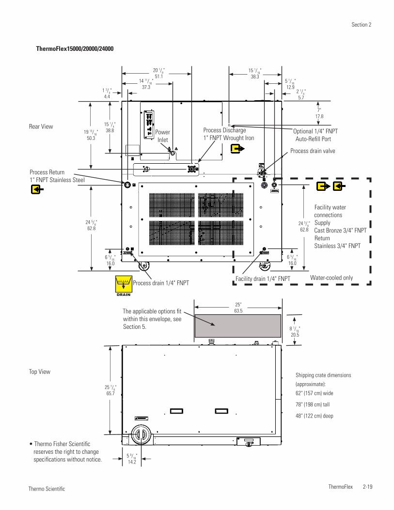
Section 2
ThermoFlex 2-19 Thermo Scientific
Shipping crate dimensions
(approximate):
62" (157 cm) wide
78" (198 cm) tall
48" (122 cm) deep
Top View
Rear View
5 9/16"14.2
8 1/16"20.5
25"63.5The applicable options fit
within this envelope, see Section 5.
25 7/8"65.7
Process Return 1" FNPT Stainless Steel
2 1/4"5.7
7"17.8
20 1/8"51.1
15 1/16"38.3
5 1/16"12.9
14 11/16"37.3
15 1/4"38.8
24 5/8"62.8
24 5/8"62.8
19 13/16"50.3
6 5/16"16.0
6 5/16"16.0
1 3/4"4.4
Facility water connectionsSupply Cast Bronze 3/4" FNPTReturn Stainless 3/4" FNPT
Facility drain 1/4" FNPTProcess drain 1/4" FNPT
Optional 1/4" FNPT Auto-Refill Port
Process drain valve
Process Discharge1" FNPT Wrought Iron
DRAIN
Water-cooled only
Power Inlet
ThermoFlex15000/20000/24000
• Thermo Fisher Scientific reserves the right to change specifications without notice.

Section 2
2-20 ThermoFlex Thermo Scientific

ThermoFlex 3-1 Thermo Scientific
Section 3 Installation
Ambient Temperature Range* 10°C to 40°C (50°F to 104°F)
Relative Humidity Range 10% to 80% (non-condensing)
Operating Altitude* Sea Level to 8000 feet (2438 meters)
Overvoltage Category II
Pollution Degree 2
Degree of Protection IP 20
Never place the chiller in a location where excessive heat, moisture, inadequate ventilation, or corrosive materials are present.
Note Refer to the nameplate information on the rear of the chiller.
Air-cooled chillers retain their full rated capacity at 20°C setpoint in ambient temperatures up to 25°C (77°F). For ambient temperatures above 25°C please de-rate the cooling capacity 3% for every 1°C above 25°C (77°F), up to a maximum ambient temperature of 40°C (104°F). Note that when operating at a process temperature lower than 20°C the de-rate percentage may increase due to additional gains from losses to ambient.
Note Depending on the setpoint and ambient temperatures, there may be a heat gain or loss through the plumbing resulting in a variation from setpoint temperature at the application inlet. Applications with large temperature variations between ambient and setpoint temperatures, and/or long plumbing lengths, may require additional insulation.
ThermoFlex2500 air-cooled chillers have a two-speed fan. Should the chiller's internal ambient temperature reach 50°C for 30 seconds, or reach 53°C, the fan speed will switch from slow speed to high speed to maintain internal temperatures within acceptable limits. When the temperature reaches 44°C or below for at least 15 minutes the speed will return to low. When in high speed the chiller's decibel level increases significantly.
Note High speed is required for the chiller to achieve its 2500 watt cooling capacity. At high-end operating conditions the fan can be set to run at high speed all the time using the controller's Setup Loop, see Section 4.
Site Requirements
*Because of the decrease in air density, maximum temperature for the air entering an air-cooled ThermoFlex is reduced by 1°C per 1,000 feet above sea level. In addition, cooling capacity is reduced 1.2% per 1,000 feet above sea level.
CAUTION

Section 3
3-2 ThermoFlex Thermo Scientific
Chillers installed below the end-user application may enable system fluid to drain back into the chiller and cause spillage. Thermo Fisher offers an anti-drainback kit to prevent any spillage, see Section 5.
Air-cooled chillers can be installed with both sides blocked, or one side and the rear. See Figure 3-1. The front of the chiller needs a minimum clearance of 24". Air will enter the front of the system and exit through the sides and rear.
Having two sides blocked can impact the chiller's performance due to changes in air flow. If your installation requires two blocked sides please ensure that the following requirements are met:
Process Setpoint Temperature: Below 30°C (86°F)
Ambient: Below 40°C (104°F)
Before operating the chiller in conditions outside any of those listed on this page please contact Thermo Fisher Scientific's Sales, Service and Customer Support to review your installation.
Figure 3-1 Minimum Clearance

Section 3
ThermoFlex 3-3 Thermo Scientific
Electrical Requirements
The chiller's construction provides protection against the risk of electrical shock by grounding appropriate metal parts. The protection will not function unless the power cord is connected to a properly grounded outlet. It is the user's responsibility to assure a proper ground connection is provided.
The chiller must be installed in accordance with the National Electrical Code and the with reference to the information on the chiller's nameplate located on the rear.
Locate the chiller so it is near, and has easy access to, its disconnecting device.
The user is responsible to ensure that the line cord provided meets local electrical codes. If not, contact qualified installation personnel.
The chiller is intended for use on a dedicated outlet. The ThermoFlex has an internal circuit protection that is equivalent (approximately) to the branch circuit rating. This is to protect the ThermoFlex, and is not intended as a substitute for branch circuit protection.
DANGER
* Refer to Appendix A for country specific ratings. Continued on next page.
Electrical Service Requirements (Standard chillers):
ThermoFlex900 Voltage ±10% Frequency Phase Branch Circuit Requirements
Line Cord Plug
100 VAC 50 Hz 1Ø 15A 5-15P
115 VAC 60 Hz 1Ø 15A 5-15P
200 VAC 50 Hz 1Ø 15A 6-15P
208-230 VAC 60 Hz 1Ø 15A 6-15P
230 VAC 50 Hz 1Ø *16A1, 15A2, 13A3 -
ThermoFlex1400 Voltage ±10% Frequency Phase Branch Circuit Requirements
Line Cord Plug
100 VAC 50 Hz 1Ø 20A 5-20P
115 VAC 60 Hz 1Ø 20A 5-20P
200 VAC 50 Hz 1Ø 15A 6-15P
208-230 VAC 60 Hz 1Ø 15A 6-15P
230 VAC 50 Hz 1Ø *16A1, 15A2, 13A3 -
ThermoFlex2500 Voltage ±10% Frequency Phase Branch Circuit Requirements
Line Cord Plug
200 VAC P 1, P 2 Pump 50 Hz 1Ø 15A 6-15P
208-230 VAC P 1, P 2 Pump 60 Hz 1Ø 15A 6-15P
200 VAC T 1 Pump 50 Hz 1Ø 20A 6-20P
208-230 VAC T 1 Pump 60 Hz 1Ø 20A 6-20P
230 VAC 50 Hz 1Ø *16A1, 15A2, 13A3 -

Section 3
3-4 ThermoFlex Thermo Scientific
Continued on next page.
Electrical Service Requirements (Standard chillers):
ThermoFlex3500/5000 Voltage ±10% Frequency Phase Branch Circuit Requirements
Line Cord Plug
200 VAC P 1, P 2 Pump 50 Hz 1Ø 15A 6-15P
200 VAC T 1, P 3 Pump 50 Hz 1Ø 20A 6-20P
200 VAC P 4 Pump 50 Hz 1Ø 30A 6-30P
208-230 VAC P 1, P 2 Pump 60 Hz 1Ø 15A 6-15P
208-230 VAC T 1, P 3 Pump 60 Hz 1Ø 20A 6-20P
208-230 VAC P 4 Pump 60 Hz 1Ø 30A 6-30P
230 VAC P 1 - P 4 Pump 50 Hz 1Ø *16A1, 15A2, 13A3 -
ThermoFlex7500/10000(Air-cooled)
Voltage ±10% Frequency Phase MCA MOPD Line Cord Plug
200 VAC P 2 Pump 50 Hz 3Ø 16.5 30 L15-20P
200 VAC P 3 Pump 50 Hz 3Ø 18.7 30 L15-20P
200 VAC P 5 Pump 50 Hz 3Ø 22.3 35 L15-30P
208-230 VAC P 2 Pump 60 Hz 3Ø 16.5 30 L15-20P
208-230 VAC P 3 Pump 60 Hz 3Ø 18.7 30 L15-20P
208-230 VAC P 5 Pump 60 Hz 3Ø 22.3 35 L15-30P
400 VAC P 2 Pump 50 Hz 3Ø 10.9 20 IEC309
400 VAC P 3 Pump 50 Hz 3Ø 9.6 15 IEC309
400 VAC P 5 Pump 50 Hz 3Ø 11.8 15 IEC309
400 VAC T 5 Pump 50 Hz 3Ø 8.9 15 IEC309
ThermoFlex7500/10000(Water-cooled)
Voltage ±10% Frequency Phase MCA MOPD Line Cord Plug
200 VAC P 2 Pump 50 Hz 3Ø 16.2 30 L15-20P
200 VAC P 3 Pump 50 Hz 3Ø 18.4 30 L15-20P
200 VAC P 5 Pump 50 Hz 3Ø 22.0 35 L15-30P
208-230 VAC P 2 Pump 60 Hz 3Ø 16.2 30 L15-20P
208-230 VAC P 3 Pump 60 Hz 3Ø 18.4 30 L15-20P
208-230 VAC P 5 Pump 60 Hz 3Ø 22.0 35 L15-30P
400 VAC P 2 Pump 50 Hz 3Ø 10.6 20 IEC309
400 VAC P 3 Pump 50 Hz 3Ø 9.3 15 IEC309
400 VAC P 5 Pump 50 Hz 3Ø 11.5 20 IEC309
400 VAC T 5 Pump 50 Hz 3Ø 8.9 15 IEC309
MCA = Minimum Current Ampacity
MOPD = Maximum Overcurrent Protective Device
Values reflect those on the nameplate located on the rear of the chiller.

Section 3
ThermoFlex 3-5 Thermo Scientific
ThermoFlex15000/20000(Air-cooled)
Voltage ±10% Frequency Phase MCA MOPD Line Cord Plug
208-230 VAC P 3 Pump 60 Hz 3Ø 32.2 60 Hard wire
208-230 VAC P 5 Pump 60 Hz 3Ø 35.8 60 Hard wire
400 VAC P 3 Pump 50 Hz 3Ø 15.9 30 Hard wire
400 VAC P 5 Pump 50 Hz 3Ø 18.1 30 Hard wire
ThermoFlex15000/20000(Water-cooled)
Voltage ±10% Frequency Phase MCA MOPD Line Cord Plug
208-230 VAC P 3 Pump 60 Hz 3Ø 28.7 50 Hard wire
208-230 VAC P 5 Pump 60 Hz 3Ø 32.3 60 Hard wire
400 VAC P 3 Pump 50 Hz 3Ø 14.5 25 Hard wire
400 VAC P 5 Pump 50 Hz 3Ø 16.7 30 Hard wire
ThermoFlex24000(Air-cooled)
Voltage ±10% Frequency Phase MCA MOPD Line Cord Plug
208-230 VAC P 3 Pump 60 Hz 3Ø 43.9 70 Hard wire
208-230 VAC P 5 Pump 60 Hz 3Ø 47.5 80 Hard wire
400 VAC P 3 Pump 50 Hz 3Ø 20.1 35 Hard wire
400 VAC P 5 Pump 50 Hz 3Ø 22.3 40 Hard wire
ThermoFlex24000(Water-cooled)
Voltage ±10% Frequency Phase MCA MOPD Line Cord Plug
208-230 VAC P 3 Pump 60 Hz 3Ø 37.1 70 Hard wire
208-230 VAC P 5 Pump 60 Hz 3Ø 40.7 70 Hard wire
400 VAC P 3 Pump 50 Hz 3Ø 18.8 35 Hard wire
400 VAC P 5 Pump 50 Hz 3Ø 21.0 35 Hard wire
For installation information on variable voltage chillers refer to Appendix B.Refer to the nameplate label located on the rear of the chiller for specific electrical requirements.
* United States and Japan only. All other plugs are country specific.
ThermoFlex900 Voltage ±10% Frequency Phase Branch Circuit Requirements
Line Cord Plug
115 VAC 60 Hz 1Ø 15A 5-15P*
100 VAC 50/60 Hz 1Ø 15A 5-15P*
ThermoFlex1400 Voltage ±10% Frequency Phase Branch Circuit Requirements
Line Cord Plug
115 VAC 60 Hz 1Ø 20A -
100 VAC 50/60 Hz 1Ø 20A -
Electrical Service Requirements (Variable voltage chillers):
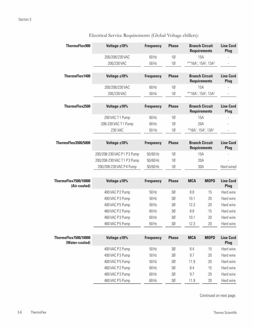
Section 3
3-6 ThermoFlex Thermo Scientific
ThermoFlex900 Voltage ±10% Frequency Phase Branch Circuit Requirements
Line Cord Plug
200/208/230 VAC 60 Hz 1Ø 15A -
200/230 VAC 50 Hz 1Ø **16A1, 15A2, 13A3 -
ThermoFlex1400 Voltage ±10% Frequency Phase Branch Circuit Requirements
Line Cord Plug
200/208/230 VAC 60 Hz 1Ø 15A -
200/230 VAC 50 Hz 1Ø **16A1, 15A2, 13A3 -
ThermoFlex2500 Voltage ±10% Frequency Phase Branch Circuit Requirements
Line Cord Plug
200 VAC T 1 Pump 60 Hz 1Ø 15A -
208-230 VAC T 1 Pump 60 Hz 1Ø 20A -
230 VAC 50 Hz 1Ø *16A1, 15A2, 13A3 -
ThermoFlex3500/5000 Voltage ±10% Frequency Phase Branch Circuit Requirements
Line Cord Plug
200/208-230 VAC P 1 P 3 Pump 50/60 Hz 1Ø 15A -
200/208-230 VAC T 1 P 3 Pump 50/60 Hz 1Ø 20A -
200/208-230 VAC P 4 Pump 50/60 Hz 1Ø 30A Hard wired
Electrical Service Requirements (Global Voltage chillers):
ThermoFlex7500/10000(Air-cooled)
Voltage ±10% Frequency Phase MCA MOPD Line Cord Plug
400 VAC P 2 Pump 50 Hz 3Ø 8.8 15 Hard wire
400 VAC P 3 Pump 50 Hz 3Ø 10.1 20 Hard wire
400 VAC P 5 Pump 50 Hz 3Ø 12.3 20 Hard wire
460 VAC P 2 Pump 60 Hz 3Ø 8.8 15 Hard wire
460 VAC P 3 Pump 60 Hz 3Ø 10.1 20 Hard wire
460 VAC P 5 Pump 60 Hz 3Ø 12.3 20 Hard wire
ThermoFlex7500/10000(Water-cooled)
Voltage ±10% Frequency Phase MCA MOPD Line Cord Plug
400 VAC P 2 Pump 50 Hz 3Ø 8.4 15 Hard wire
400 VAC P 3 Pump 50 Hz 3Ø 9.7 20 Hard wire
400 VAC P 5 Pump 50 Hz 3Ø 11.9 20 Hard wire
460 VAC P 2 Pump 60 Hz 3Ø 8.4 15 Hard wire
460 VAC P 3 Pump 60 Hz 3Ø 9.7 20 Hard wire
460 VAC P 5 Pump 60 Hz 3Ø 11.9 20 Hard wire
Continued on next page.

Section 3
ThermoFlex 3-7 Thermo Scientific
** Chillers selected for 230 VAC operation have a range of -10% to +7%. Refer to Appendix A for country specific ratings.
For installation information on global voltage chillers refer to Appendix B.Refer to the nameplate label located on the rear of the chiller for specific electrical requirements.
ThermoFlex15000/20000(Air-cooled)
Voltage ±10% Frequency Phase MCA MOPD Line Cord Plug
400 VAC P 3 Pump 50 Hz 3Ø 16.2 30 Hard wire
400 VAC P 5 Pump 50 Hz 3Ø 18.4 30 Hard wire
460 VAC P 3 Pump 60 Hz 3Ø 16.2 30 Hard wire
460 VAC P 5 Pump 60 Hz 3Ø 18.4 30 Hard wire
ThermoFlex15000/20000(Water-cooled)
Voltage ±10% Frequency Phase MCA MOPD Line Cord Plug
400 VAC P 3 Pump 50 Hz 3Ø 14.5 25 Hard wire
400 VAC P 5 Pump 50 Hz 3Ø 16.7 30 Hard wire
460 VAC P 3 Pump 60 Hz 3Ø 14.5 25 Hard wire
460 VAC P 5 Pump 60 Hz 3Ø 16.7 30 Hard wire
ThermoFlex24000(Air-cooled)
Voltage ±10% Frequency Phase MCA MOPD Line Cord Plug
400 VAC P 3 Pump 50 Hz 3Ø 20.1 35 Hard wire
400 VAC P 5 Pump 50 Hz 3Ø 22.3 40 Hard wire
460 VAC P 3 Pump 60 Hz 3Ø 20.1 35 Hard wire
460 VAC P 5 Pump 60 Hz 3Ø 22.3 40 Hard wire
ThermoFlex24000(Water-cooled)
Voltage ±10% Frequency Phase MCA MOPD Line Cord Plug
400 VAC P 3 Pump 50 Hz 3Ø 18.8 35 Hard wire
400 VAC P 5 Pump 50 Hz 3Ø 21.0 35 Hard wire
460 VAC P 3 Pump 60 Hz 3Ø 18.8 35 Hard wire
460 VAC P 5 Pump 60 Hz 3Ø 21.0 35 Hard wire
MCA = Minimum Current Ampacity
MOPD = Maximum Overcurrent Protective Device
Values reflect those on the nameplate located on the rear of the chiller .

Section 3
3-8 ThermoFlex Thermo Scientific
Hard Wire Installation For personal safety and equipment reliability, only a qualified technician should perform the following procedure.
Note The technician is responsible for installing circuit protection for incoming power. Before wiring consult the nameplate on the rear of the chiller. Ensue installation is in accordance with the National Electrical Code and any other applicable country and local codes.
For ThermoFlex900 through 10000 chillersRemove the six screws securing the electrical box cover to the chiller.• Remove the double knock out ( • 7/8" and 1 3/32").Insert the cable through the hole.• Refer to the label in the electrical box to configure your chiller, see Figure 3-3.• Secure the cable's ground wire to the ground stud.• Reinstall the cover.•
For ThermoFlex15000, 20000 and 24000 chillers Remove the five screws securing the electrical panel to the chiller.• Refer to the label in the electrical box to configure your chiller, see Figure 3-3.• Secure the cable's ground wire to the ground stud.• Reinstall the panel..•
(2)
Terminal Block
Ground Stud Knock Out
(2)
(2)
Figure 3-2 Electrical Box
Figure 3-3 Sample Label
WARNING

Section 3
ThermoFlex 3-9 Thermo Scientific
Plumbing Requirements
Ensure that all shipping plugs are removed before installation.
Never connect the process fluid lines to your facility water supply or any pressurized liquid source.
To prevent damage to the chiller's plate exchanger, centrifugal pumps require a 4.0 gpm (15.1 lpm) minimum flow rate.
P 1 and P 2 pumps are capable of producing 185 psig. Ensure your plumbing is rated to withstand this pressure at your operating temperature. An external pressure relief valve is available, see Section 5.
Note Ensure your plumbing installation develops a back pressure to the ThermoFlex greater than 3 PSIG. Lower pressure will shut down the chiller.
The process fluid connections are located on the rear of the chiller and are labeled (PRoCESS ouTLET) and (PRoCeSS InLeT).
Process Fluid Connections (FNPT)outlet ThermoFlex900 - 10000 P 1 P 2 T 0 T 1 1/2" cast bronzeThermoFlex3500 - 5000 P 3 P 4 3/4" cast bronzeThermoFlex7500 - 24000 P 3 P 5 T 5 1" wrought copperInlet - Same size as outlet all connections stainless steel
Supplied AdaptersP 1 P 2 T 0 T 1 1/2" x 3/8'' Polyethylene and 1/2" x 1/2" Nylon P 3 P 4 3/4 MPT x 1/2 barb PVCP 3 P 5 T 5 1" MPT x 1" Barb PVC and 1" MPT x 3/4" Barb PVC
CAUTION
CAUTION
CAUTION
1/4" Female NPT Riton Reservoir Drain Plug
See Section 2 for the specific locations on your chiller.
Figure 3-4 Typical Plumbing Connections (1 of 2)DRAIN
Stainless steel outlet connection for chillers with P 1/P 2 pumps and a flow transducer

Section 3
3-10 ThermoFlex Thermo Scientific
Water-cooled Chillers For water-cooled chillers the facility water plumbing connections are also located on the rear and are labeled FACILITY InLeT and FACILITY ouTLET. The connections are ½" Female NPT for ThermoFlex900 - 5000, ¾" Female NPT for ThermoFlex7500 - 24000. Both connections for ThermoFlex900 to 10000 are cast bronze. The supply connections for ThermoFlex15000 to 24000 are cast bronze, the return connections are stainless steel.
Connect the FACILITY InLeT to your facility water supply. Connect the FACILITY ouTLeT to your facility water return or drain. Ensure all connections are secure and that the proper sealant/lubricant for the fitting material is used. (If Teflon® tape is used, ensure the tape does not overhang the first thread as it could shred and get into the fluid.)
Connect the PRoCESS ouTLET to the fluid inlet on your application. Connect the PRoCeSS InLeT to the fluid outlet on your application. Ensure all connections are secure and that the proper sealant/lubricant for the fitting material is used. (If Teflon® tape is used, ensure the tape does not overhang the first thread as it could shred and get into the fluid.) Keep the distance between the chiller and the instrument being cooled as short as possible. Ensure tubing is straight and without bends. If diameter reductions are required, make them at the inlet and outlet of your application, not at the ThermoFlex.
Figure 3-4 Typical Plumbing Connections (2 of 2)
Process Fluid Flow
Process Fluid Flow
Application
Figure 3-5 Typical Plumbing Connections, Water-cooled Chillers
See Section 2 for the specific locations on your chiller.

Section 3
ThermoFlex 3-11 Thermo Scientific
Process Fluid Requirements
Do not use automotive antifreeze. Commercial antifreeze contains silicates that can damage the pump seals. Use of any fluid not listed below will void the manufacturer’s warranty.
Approved fluids are:
Filtered/Single Distilled water
0 - 75% Ethylene Glycol/Water
0 - 75% Propylene Glycol/Water
Deionized water (1 - 3 MΩ-cm, compensated)
Ethylene glycol (EG) is poisonous and flammable. Before using any fluid or performing maintenance where contact with the fluid is likely refer to the manufacturer’s most current MSDS for handling precautions.
EG is also hygroscopic, it will absorb water from its environment. This can affect the freezing point and boiling point of the fluid over time and may result in system failure.
To prevent freezing/glazing of the plate exchanger, ThermoFlex7500 through 24000 chillers require the use of 50/50 EG/water or 50/50 PG/water below 10°C process temperature.
When using a process fluid mixture of ethylene glycol and water or propylene glycol and water, check the fluid concentration and pH on a regular basis. Changes in concentration and pH can impact system performance.
When using EG/water or PG/water, top-off with plain water. After top-off check the fluid concentration.
Do not use a Deionization (DI) filter cartridge with Inhibited EG or Inhibited PG. A DI filter will remove inhibitors from the solution rendering the fluid ineffective against corrosion protection. Also, inhibitors increase fluid conductivity.
WARNING
WARNING
CAUTION
CAUTION
CAUTION
CAUTION
CAUTION

Section 3
3-12 ThermoFlex Thermo Scientific
Compatibility with Approved
Fluids
Filtered Tap Water/Single Distilled Water Filtered drinking water and single distilled water are good choices for recirculating chillers because the filtering/distilling process used removes microorganisms that could create biological fouling as well as harmful particulates and excessive minerals that could cause deposits and scaling.
Chlorine Short term usage of tap water may not cause any adverse affects on the chiller or your application, but in the long term problems may arise. To help alleviate these problems Thermo Fisher Scientific recommends the use of chlorine.
The duration of time that chlorine remains in solution depends on factors such as water temperature, pH and availability of direct sunlight. We recommend maintaining chlorine levels at proper levels using chlorine test strips, generally 1 to 5 ppm is adequate.
For best results, maintain the pH of the fluid between 6.5 and 7.5. Do not add additional chlorine without first determining the concentration ratio that already exists in the fluid supply. Corrosion and degradation of the circulation components can result from concentration ratios that are too high. Contact our customer support for additional information.
Deionized Water Deionized water is water that has had its mineral ions removed using ion exchange resins. The purpose of this process is to remove the ions that allow electrical current to flow more easily through water. This helps to prevent electrical leaks to ground through the recirculating fluid. Deionized water is classified by the electrical resistance of the water, usually measured in MΩ/cm, with pure water having a resistance of 18 MΩcm.
Water that has been deionized is in an unbalanced state and will leach the missing ions from the materials it comes in contact with. The aggressive nature of this leaching can cause pitting on metal surfaces. It should also be noted that the deionizing process does not remove microorganisms. Because of this, it is recommended that only applications that have a specified requirement for deionized water should use deionized water.
In any case, only deionized water with a resistivity between 1 and 3 MΩcm is approved for use in Thermo Fisher Scientific recirculating chillers.
Recommended Biocides and Inhibitors Thermo Fisher Scientific offers a biocide and inhibitor package (NALCO) premixed with 5 gallons of water or as a kit to be added to water. No other biocide or inhibitor is recommended for use in our recirculating chillers.
Biocides are corrosive and can cause irreversible eye damage and skin burns. They are harmful if inhaled, swallowed or absorbed through the skin. Refer to the manufacturer's most current MSDS. WARNING

Section 3
ThermoFlex 3-13 Thermo Scientific
Uninhibited Ethylene Glycol/Water Ethylene glycol is used to depress the freezing point of water and should only be used at temperatures where freeze point suppression is required. Ethylene glycol does not improve heat transfer and is not recommended for use as a biocide. Because glycols lower the surface tension of water and do not evaporate as readily as water, they may cause visible weepage past the pump seals. If weepage cannot be tolerated, seal-less, magnetically driven pumps should be used where available.
Uninhibited simply means that the glycol does not contain any additives to prevent corrosion. While uninhibited ethylene glycol is acceptable for use, the pH level must be closely monitored and the fluid may need to be replaced more often. All glycols produce acids in the presence of air and the fluid should be changed if the pH falls below 8. Note that litmus paper will not work to test the pH of ethylene glycol/water.
Inhibited Ethylene Glycol/Water Inhibited glycol can help protect the wetted metals within the cooling circuit from corrosion caused by poor water quality, ethylene glycol oxidation (low pH) and mixed metals (electrolysis). The inhibitor works by either leaving a barrier coating on metal surfaces to buffer them from the corrosive fluid or by creating an oxidized layer that protects the underlying metal (passivating).
Inhibited automotive glycols are never acceptable. They use either silicates or Organic Acid Technology (OAT) as the inhibitor and these components are not compatible with the polymers used in recirculating chillers including the pump seals and internal hoses.
Inhibitors may also accelerate pump seal wear and seal-less, magnetically driven pumps should be used where available.
Uninhibited Propylene Glycol/Water Propylene glycol does not transfer heat as well as ethylene glycol, but can be used when freeze point suppression is required as well as lower toxicity.
Propylene glycol does not function as a biocide and the pH needs to be maintained the same as with ethylene glycol as it also produces acid when oxidized.
Inhibited Propylene Glycol/Water Inhibited propylene glycol has the same properties as uninhibited propylene glycol and the same concerns as inhibited ethylene glycol.

Section 3
3-14 ThermoFlex Thermo Scientific
Process Fluid Permissible (PPM) Desirable (PPM)
Microbiologicals (algae, bacteria, fungi) 0 0
Inorganic ChemicalsCalcium <25 <0.6Chloride <25 <10 Copper <1.3 <1.00.020 ppm if fluid in contact with aluminumIron <0.3 <0.1Lead <0.015 0Magnesium <12 <0.1Manganese <0.05 <0.03Nitrates\Nitrites <10 as N 0Potassium <20 <0.3Silicate <25 <1.0Sodium <20 <0.3Sulfate <25 <1Hardness <17 <0.05Total Dissolved Solids <50 <10
Other ParameterspH 6.5-8.5 7-8Resistivity 0.01* 0.05-0.1*
* MΩ-cm (compensated to 25°C)
unfavorably high total ionized solids (TIS) can accelerate the rate of galvanic corrosion. These contaminants can function as electrolytes which increase the potential for galvanic cell corrosion and lead to localized corrosion such as pitting. Eventually, the pitting will become so extensive that refrigerant will leak into the water reservoir.
As an example, raw water in the united States averages 171 ppm (of NaCl). The recommended level for use in a water system is between 0.5 to 5.0 ppm (of NaCl).
Recommendation: Initially fill the tank with distilled or deionized water within a range of 1-3 MΩ-cm. (It is acceptable to have the fluid drop to the
Process Water Quality and
Standards
When using the ThermoFlex chiller to circulate through aluminum, a compatible corrosion inhibitor should be utilized to prevent galvanic corrosion.
Fluid viscosity should be 50 cSt or less at the lowest temperature used.
Visible pump weepage may occur when compatible glycols, oils or other additives are used. Pump weepage is considered as a normal operating condition of mechanical seal pumps.
Additional Fluid Information

Section 3
ThermoFlex 3-15 Thermo Scientific
Facility Water Quality and
Standards (water-cooled
chillers)
Facility Water Permissible (PPM) Desirable (PPM)
Microbiologicals (algae, bacteria, fungi) 0 0
Inorganic ChemicalsCalcium <40 <0.6Chloride <250 <25 Copper <1.3 <1.00.020 ppm if fluid in contact with aluminumIron <0.3 <0.1Lead <0.015 0Magnesium <12 <0.1Manganese <0.05 <0.03Nitrates\Nitrites <10 as N 0Potassium <20 <0.3Silicate <25 <1.0Sodium <20 <0.3Sulfate <250 <50Hardness <17 <0.05Total Dissolved Solids <50 <10
Note A corrosion inhibitor is recommended if mixed metals are in the facility water loop.
other levels over-time.) Do not use untreated tap water as the total ionized solids level may be too high. This will reduce the electrolytic potential of the water and prevent or reduce the galvanic corrosion observed.

Section 3
3-16 ThermoFlex Thermo Scientific
Facility Water Maximum Inlet Pressure must not exceed 150 PSIG.
Facility Water Maximum Pressure Differential must not exceed 50 PSID. (Pressure Differential = Inlet Pressure - outlet Pressure)
Note Before using facility water that is above 35°C contact Thermo Fisher Scientific.
The facility water must meet the following conditions for the chiller to maintain its full rated capacity.
Faci
lity
Pre
ssur
e D
rop
PS
ID
0 0.5 1.0 1.5 2.0 2.5 3.0 3.5 Facility Flow - GPM
Faci
lity
Tem
pera
ture
°C
45403530252015105
4.54.03.53.02.52.01.51.00.5
°CPSID
Facility Water Requirements
(water-cooled chillers)
ThermoFlex1400 Example:Follow the lines.Start with a known, e.g., facility water temperature.A - go across to temperature curveB - drop down to determine the minimum required facility flow.C - Where B crosses the PSID curve, go across to determine the minimum required PSID.
AB
C
Faci
lity
Pre
ssur
e D
rop
PS
ID
2 4 6 8 Facility Flow - GPM
Faci
lity
Tem
pera
ture
°C
45403530252015105
30
25
20
15
10
5
°C
PSID
ThermoFlex2500
AB
C
Faci
lity
Tem
pera
ture
°C
45403530252015105
2 4 6 8 10 Facility Flow - GPM
Faci
lity
Pre
ssur
e D
rop
PS
ID
45403530252015105
°C
PSID
ThermoFlex3500/5000
A
BC
Example: See above.
Example: See above.
CAUTION

Section 3
ThermoFlex 3-17 Thermo Scientific
Faci
lity
Tem
pera
ture
°C
5 10 15 20 Facility Flow - GPM
Faci
lity
Pre
ssur
e D
rop
PS
ID
30
25
20
15
10
5
°C
PSID
ThermoFlex7500/10000
ThermoFlex15000/20000
ThermoFlex24000
Example: See below.
Example: See below.
Example:Follow the lines.Start with a known, e.g., facility water temperature.A - go across to temperature curveB - go down or up to determine the minimum required facility flow.C - Where B crosses the PSID curve, go across to determine the minimum required PSID.
A
B
C
Faci
lity
Tem
pera
ture
°C
Faci
lity
Tem
pera
ture
°C
40
35
30
25
20
15
10
5
40
35
30
25
20
15
10
5
5 10 15 20 25 30 Facility Flow - GPM
5 10 15 20 25 30 Facility Flow - GPM
Faci
lity
Pre
ssur
e D
rop
PS
IDFa
cilit
y P
ress
ure
Dro
p P
SID
60
50
40
30
20
10
30
25
20
15
10
5
PSID
PSID
A
A
B
B
C
C
40
35
30
25
20
15
10
5
°C
°C

Section 3
3-18 ThermoFlex Thermo Scientific
Initial Filling Ensure the reservoir drain plug on the back of the chiller is in place, or the Riton fitting is closed, and that all plumbing connections are secure.
Before using any fluid refer to the manufacturer’s MSDS for handling precautions.
The reservoir has a sight tube and ball for easy fluid level monitoring. Slowly fill the reservoir with clean process fluid through the funnel only, failure to comply may result in internal spillage.
Note Filling the reservoir above MAX LeVeL fill line will result in an over flow error (O FLO) causing the chiller to shut down.
Since the reservoir capacity may be small compared to your application and air may need to be purged from the lines, have extra cooling fluid on hand to keep the system topped off when external circulation is started.
Figure 3-6 Reservoir Cap
Before replacing the reservoir cap ensure the reservoir sight tube ball stopper is securely in place, see next page.
Replace the reservoir cap by screwing it clockwise. Cap should be hand tight.
Reservoir Sight Tube & BallMAX
LEVEL
MIN LEVEL
Figure 3-7 Reservoir Sight Tube & Ball
WARNINGLocate and remove the reservoir cap by unscrewing it counterclockwise.
To prevent the introduction of particulates into the system, fill the chiller with the reservoir bag filter in place. Chillers are shipped with a bag filter in place. For information on changing the bag filter, see Section 6.
CAUTION

Section 3
ThermoFlex 3-19 Thermo Scientific
Fluid Top Off Remove the reservoir cap by unscrewing it counterclockwise.
To prevent the introduction of particulates into the system, fill the chiller with the reservoir bag filter in place. Chillers are shipped with a bag filter in place. For information on changing the bag filter, see Section 6.
The reservoir has a sight tube and ball for easy fluid level monitoring. Slowly fill the reservoir with clean process fluid through the funnel only, failure to comply may result in internal spillage.
Note Filling the reservoir above MAX LeVeL fill line will result in an over flow error (O FLO) causing the chiller to shut down. Also, fluids expand when heated.
Note Adding fluid that has a temperature differential with the fluid already in the reservoir will temporarily affect the chiller's stability performance.
Before replacing the reservoir cap ensure the reservoir sight tube ball stopper is securely in place.
Reservoir Ball Stopper
Figure 3-8 Reservoir Ball Stopper
CAUTION

Section 3
3-20 ThermoFlex Thermo Scientific

ThermoFlex 4-1 Thermo Scientific
Basic Controller
Section 4 Operation
The controller controls temperature using a Proportional-Integral-Derivative (PID) algorithm. It is designed with an easy to use operator interface.
This key is used to start and stop the chiller.
This key is used to navigate through the controller displays, to make changes and to save changes once they are made. It is also used to clear error codes.
This key is also used to navigate through controller displays.
The up arrow key is used to navigate through the controller displays and to increase adjustable values.
The down arrow key is used to navigate through the controller displays and to decrease adjustable values.
Figure 4-1 Basic Controller
mode
enter
+
-enter
mode
+
-

Section 4
4-2 ThermoFlex Thermo Scientific
Start Up
Setup Note For first time use, please refer to the quick start instructions included with your chiller or the copy in this manual. The manual's version follows the Table of Contents.
Before starting the chiller, double check all electrical and plumbing connections. Have extra recirculating fluid on hand. If the chiller will not start refer to Section 7 Troubleshooting.
If the chiller is equipped with a deionization filter cartridge refer to Section 5 for installation.
• Place the optional GFCI breaker located on the rear to the up position.
• For ThermoFlex900 through 10000s, place the circuit protector located on the rear to the on ( I ) position. The display will indicate a series of upward scrolling bars ( ).
• For ThermoFlex15000 and 24000s, the display will indicate a series of upward scrolling bars ( ) as soon as power is supplied.
• The bars will scroll upward indicating the controller is initializing. The initialization takes approximately 15 seconds.
• When the bars disappear the controller display will go blank.
• Press the key on the controller. The controller will show the process fluid temperature. The pump and refrigeration system will also start. Note You can press the key anytime after placing the circuit protector to the on position.
If the auto restart is enabled and the chiller shuts down as a result of a power failure, when power is restored the chiller will automatically restart. Auto restart is enabled using the Setup Loop, see Setup Loop in this Section.
Note After initial start up, check your plumbing for leaks.
CAUTION

Section 4
ThermoFlex 4-3 Thermo Scientific
If desired, press the key to display the pump's discharge pressure - P 1. The display will alternate between P 1 and the pump's discharge pressure value.
If the chiller is equipped with an optional flow transducer, pressing again will display the flow rate - FLo. The display will alternate
between FLo and the flow rate value.
After displaying P1 or FLo for 60 seconds, if the key is not depressed the display will automatically revert to the process fluid temperature.
Press again to display the process fluid temperature.
P 1 - Pump discharge pressure in PSI, bar or kPa*.
FLo - Flow rate in liters or gallons per minute* (optional feature).
* See Setup Loop in this Section to change displayed scales.
indicates the controller display is alternating between the two displays.
Figure 4-2 Main Loop
FLo
xx.x C
xx
xx
P1

Section 4
4-4 ThermoFlex Thermo Scientific
mode mode modemode
Controller Loops The controller has the capability to display various loops which indicate operating conditions and parameters. The loops are selected and changed by pressing the appropriate keys.
When the controller is first powered up it goes through a short initialization (~15 seconds) and then displays the process fluid temperature. Use the key combination shown below to scroll through the loops.
SP is the Setpoint Loop and is used to display and change the setpoint. The setpoint is the desired process fluid temperature needed for your application. The Setpoint Loop is accessed by pressing the key, see next page.
SEtuP is the Setup Loop. The Setup Loop allows you to display and/or alter different parameters of the controller. The Setup Loop is accessed from the SP display by pressing the key.
diA is the Diagnostic Loop. The Diagnostic Loop allows you to display the operating times for various components. The Diagnostic Loop is accessed from the Setup display by pressing the key, see Section 6 for more details.
Note The loops can be accessed and changed without the chiller running as long as the circuit protector (ThermoFlex900-10000s) is in the on ( I ) position.
Figure 4-3 Controller Loops (Chiller running)
SP SEtuP diA
xx.x C
Figure 4-4 Controller Loops (Chiller not running)
mode mode modemode
SP SEtuP diA

Section 4
ThermoFlex 4-5 Thermo Scientific
SP
xx.x C
xx.x C
mode
enter enter
Setpoint Loop ( )
• Ensure the controller is either a blank screen or displaying the process fluid temperature.
• Press the key and the controller display will alternate between SP and the setpoint value.
• If no change is required press the key to return the controller to the previous display.
• If a setpoint change is required, use the keys.
The setpoint range is +5°C to +40°C (41°F to 104°F).
Note If the are not used within one minute the controller will time out and return to the previous display, any changes will not be saved.
• Once the desired value is displayed press the key to confirm the change.
• The controller will return to the process fluid temperature display or a blank screen.
indicates the controller display is alternating between the two displays.
Figure 4-5 Setpoint Loop
or

Section 4
4-6 ThermoFlex Thermo Scientific
Setup Loop ( )
Use the Setup Loop to adjust/verify the following controller settings.
• Scales: temperature in °C or °F, flow in liters per minute or gallons per minute (only chillers with an optional flow transducer), and pressure in PSI, bar or kPa
• High and low temperature alarm limits• High and low pump discharge pressure alarm limits and time delays• Chiller reaction to a temperature, pressure or flow (optional) alarm limit
(continue to run or shut down)• Audible alarm enabled/disabled• View/change the fan speed (ThermoFlex2500 air-cooled only)• Auto restart feature enabled/disabled• Preventive care cleaning frequency reminder for air and fluid filters
Optional Features:• Global voltage• Analog I/O• Auto refill alarm• DI filter cartridge preventive maintenance interval• High/low flow alarm limits• Serial communications• Anti drainback valve position
• Save or not save all changes
To enter the Setup Loop ensure the controller display is either a blank screen (chiller off) or displaying the process fluid temperature. Press the
key and the display will indicate SP, press it again to display SEtuP.
Press the key to continue, or press twice to return to the process fluid temperature or blank display.
Use to sequence down through the loop. Use to sequence back through the loop up to the Hi t display, see next page.
To change any parameter:
Press the key.
Use the keys to change a displayed value.
Press key to confirm the change and bring up the next display.

Section 4
ThermoFlex 4-7 Thermo Scientific
diA9SP SEtuP
enter
mode mode mode mode
xx.x C xx.x C
xx
xx
Hi t
UnitS
Lo t Lo t
xx
xx
xx
xx
Hi P1
Lo P1
Hi P1
dELAY enter
enterenter
enter
enter
enter
enter
enter
enter
Hi t
UnitS degx
Lo P1
Figure 4-6 Setup Loop (All Chillers)
or or
Continued on next page.
• UnitS are the temperature, fluid flow (only chillers with an optional flow transducer) and pressure display scales. Scales: °C or °F Defaults: °C GPM or LPM GPM PSI, Bar or kPa PSI • Hi t is the fluid's High Temperature alarm limit. Range: +3°C to +42°C Default: +42°C Exceeding this limit flashes Hi t and, if enabled, sounds the alarm. The chiller reaction depends on the alarm configuration (see ALr on next page).
• Lo t is the fluid's Low Temperature alarm limit. Range: +3°C to +42°C Default: +3°C Falling below this limit flashes Lo t and, if enabled, sounds the alarm. The chiller reaction depends on the alarm configuration (see ALr on next page).
• Hi P1 is the pump's High Pressure discharge alarm limit. T 1 T 0 Pump Range: 3 to 100 PSI Default: 100 PSI T 5 Pump Range: 2 to 105 PSI Default: 105 PSI P 1 P 2 Pump Range: 3 to 100 PSI Default: 100 PSI P 3 Pump 60Hz Range: 3 to 46 PSI Default: 46 PSI P 3 Pump 50Hz Range: 3 to 32 PSI Default: 32 PSI P 4 Pump 60Hz Range: 3 to 85 PSI Default: 85 PSI P 4 Pump 50Hz Range: 3 to 60 PSI Default: 60 PSI P 5 Pump 60Hz Range: 3 to 87 PSI Default: 87 PSI P 5 Pump 50Hz Range: 3 to 56 PSI Default: 56 PSI Exceeding this limit flashes Hi P1 and, if enabled, sounds the alarm (see Sound on next page).
• dELAY is the length of time the pump can exceed the Hi P1 alarm limit. Note This feature is only active if the chiller is configured to shut down with a pressure alarm. P 1, P 2, T 0 and T 1 Range: 0 to 30 seconds Default: 0 seconds P 3 - P 5, T 5 Range: 0 to 60 seconds Default: 0 seconds Exceeding this limit flashes Hi P1 and, if enabled, sounds the alarm. The chiller reaction depends on the alarm configuration (see ALr on next page).

Section 4
4-8 ThermoFlex Thermo Scientific
Figure 4-6 Setup Loop (All Chillers)
• Lo P1 is the pump's Low Pressure discharge alarm limit. T 0 T 1 Pump Range: 3 to 100 PSI Default: 4 PSI T 5 Pump Range: 2 to 105 PSI Default: 2 PSI P 1 P 2 Pump Range: 3 to 100 PSI Default: 4 PSI P 3 Pump 60Hz Range: 3 to 46 PSI Default: 4 PSI P 3 Pump 50Hz Range: 3 to 32 PSI Default: 4 PSI P 4 Pump 60Hz Range: 3 to 85 PSI Default: 4 PSI P 4 Pump 50Hz Range: 3 to 60 PSI Default: 4 PSI P 5 Pump 60Hz Range: 3 to 87 PSI Default: 4 PSI P 5 Pump 50Hz Range: 3 to 56 PSI Default: 4 PSI Going below this limit flashes Lo P1 and, if enabled, sounds the alarm.
• dELAY is the length of time the pump can exceed the Lo P1 alarm limit. Note This feature is only active if the chiller is configured to shut down with a pressure alarm. Range: 0 to 30 seconds Default: 10 seconds Exceeding this limit flashes Lo P1 and, if enabled, sounds the alarm. The chiller reaction depends on the ALr alarm configuration set below.
• ALr is used to configure the chiller's reaction for exceeding an alarm limit (temperature, pressure and optional flow). The chiller will either shut down (FLt) or continue to run (indC). In each configuration, the controller will display the error code and sound the audible alarm, if enabled. Range: FLt or indC Default: FLt
• FAnSP is used to control the fan speed (air-cooled 2500 only). Auto allows the fan to run under the conditions listed in Section 3. Selecting Hi allows the fan to run at high speed all the time. Note Hi is required for chillers to achieve a ThermoFlex2500 watt cooling capacity. Range: Auto or Hi Default: Auto
• Sound is used to enable/disable the audible alarm. Range: on or oFF Default: on
Continued on next page.
Continued from previous page
enter
enterenter
Sound
FAnSP
ALr
Lo P1 Lo P1 xx
xx
on
Auto
oFF
Hi
Sound
FAnSP
enter
enter
StArt
ALrenterFLt
indCenter
enter
enter
dELAY

Section 4
ThermoFlex 4-9 Thermo Scientific
Figure 4-6 Setup Loop (All Chillers)
Save all changesDo not save all changes
• StArt is used to enable/disable the auto restart function. When enabled the chiller will automatically restart after a power failure or power interruption condition. Range: on or oFF Default: oFF
• CArE is used to set the preventive care cleaning frequency reminder for the chiller's air and fluid filters, in hours. The time selected is based on your operating environment, see Section 6. Range: off Default: L1 L1 (1000 hours) L2 (2000 hours) L3 (3000 hours) Off disables the reminder. Exceeding this limit flashes FLtrS, see Section 6.
Note If your chiller is equipped with any of the Optional Features refer to the next page.
When the display indicates StorE press to save all changes or press to not save all changes. The display will return either the process fluid temperature or, if the chiller was off when you entered the loop, a blank screen.
Continued from previous page
xx
on
oFF
LxCArE
AUto
StorE
StArt
CArE enter
enter
enter
enter

Section 4
4-10 ThermoFlex Thermo Scientific
Figure 4-7 Setup Loop (Optional Features)
Continued on next page.
xx
xxx
xx
xx
FLt
indC
xx
di t
SEc
HZ
ALr
di t
FiLL
LoFLO
HiFLO HiFLO enter
enter
enter
enter
enter
enter
enter
enter
enter
OPT
HZ
CArE• HZ is used to identify the incoming frequency for chiller's with P 3 - P 5 pumps and the capability to run on either 50 Hz or 60 Hz. The selected frequency automatically adjusts the firmware's fixed high pressure default setting. Range: 50 Hz or 60 Hz Default: 60 Hz
• OPt is used to configure the analog in/out mode of operation. See Appendix C.
• FiLL is used to set the time limit the auto refill has for filling the reservoir to the normal operating level. Range: 0 to 900 seconds Default: 45 seconds ThermoFlex900 - 5000 80 seconds ThermoFlex7500 - 24000 Exceeding the time limit flashes rEFiL and the auto refill will shut off. The chiller's reaction depends on the alarm ALr setting, Flt is shut down, indC is continue to run. Note Setting the time limit to 0 disables the auto refill option. See Section 5 for additional information.
• di t is used to set the preventive care cleaning frequency reminder for the chiller's DI filter cartridge. Range: 0 to 9999 hours Default: 448 hours Exceeding the limit flashes di, see Section 6.
• HiFLO is used to set the high flow alarm limit. T 0 T 1 Range: 0.0 to 10.5 GPM Default: 0.0 GPM T 5 Pump Range: 0.0 to 15.0 GPM Default: 0.0 GPM P 1 Pump Range: 0.0 to 10.5 GPM Default: 0.0 GPM P 2 Pump Range: 0.0 to 10.5 GPM Default: 0.0 GPM P 3 Pump Range: 0.0 to 30.0 GPM Default: 0.0 GPM P 4 Pump Range: 0.0 to 30.0 GPM Default: 0.0 GPM P 5 Pump Range: 0.0 to 30.0 GPM Default: 0.0 GPM
Exceeding a high limit flashes HiFLO and, if enabled, sounds the alarm. The chiller's reaction depends on the alarm (ALr) setting.
Note This feature is not enabled until the value is changed to something other than 0.0.
Shaded displays only appear on chillers equipped with that option.

Section 4
ThermoFlex 4-11 Thermo Scientific
Save all changesDo not save all changes
Figure 4-7 Setup Loop (Optional Features)
• LoFLO is used to set the low flow alarm limit. T 0 Pump Range: 0.0 to 10.5 GPM Default: 0.0 GPM T 1 Pump Range: 0.0 to 10.5 GPM Default: 0.0 GPM T 5 Pump Range: 0.0 to 15.0 GPM Default: 0.0 GPM P 1 Pump Range: 0.0 to 10.5 GPM Default: 0.0 GPM P 2 Pump Range: 0.0 to 10.5 GPM Default: 0.0 GPM P 3 Pump Range: 0.0 to 30.0 GPM Default: 0.0 GPM P 4 Pump Range: 0.0 to 30.0 GPM Default: 0.0 GPM P 5 Pump Range: 0.0 to 30.0 GPM Default: 0.0 GPM
Going below the low limit flashes LoFLO and, if enabled, sounds the alarm. The chiller's reaction depends on the alarm (ALr) setting.
This feature is not enabled until the value is changed to something other than 0.0. If the feature is not enabled and the flow rate drops below the flow rate listed below the chiller will continue to run and the controller will flash between FLo and LoFLo.
P 1, T 0, T 1 and T 5 Pump 0.3 GPM P 2 Pump 1.0 GPM P 3, P 4 and P 5 Pump 4.0 GPM
• SEr is used to configure the serial communications mode of operation. See Appendix D.
Note Keypad operation is still available with serial com-munications enabled.
• drAin is used to open and close the chiller's anti drainback valve for draining, see Section 5. Range: yes or no Default: no
Note The chiller must be off to drain the valve. The valve automatically closes when you exit the drAin display.
When the display indicates StorE press to save all changes or press to not save all changes. The display will return either the process fluid temperature or, if the chiller was off when you entered the loop, a blank screen.
Continued from previous page
yES
nodrAin
StorE
drAin enterenter
SEr
xxxxLoFLO LoFLO enterenter
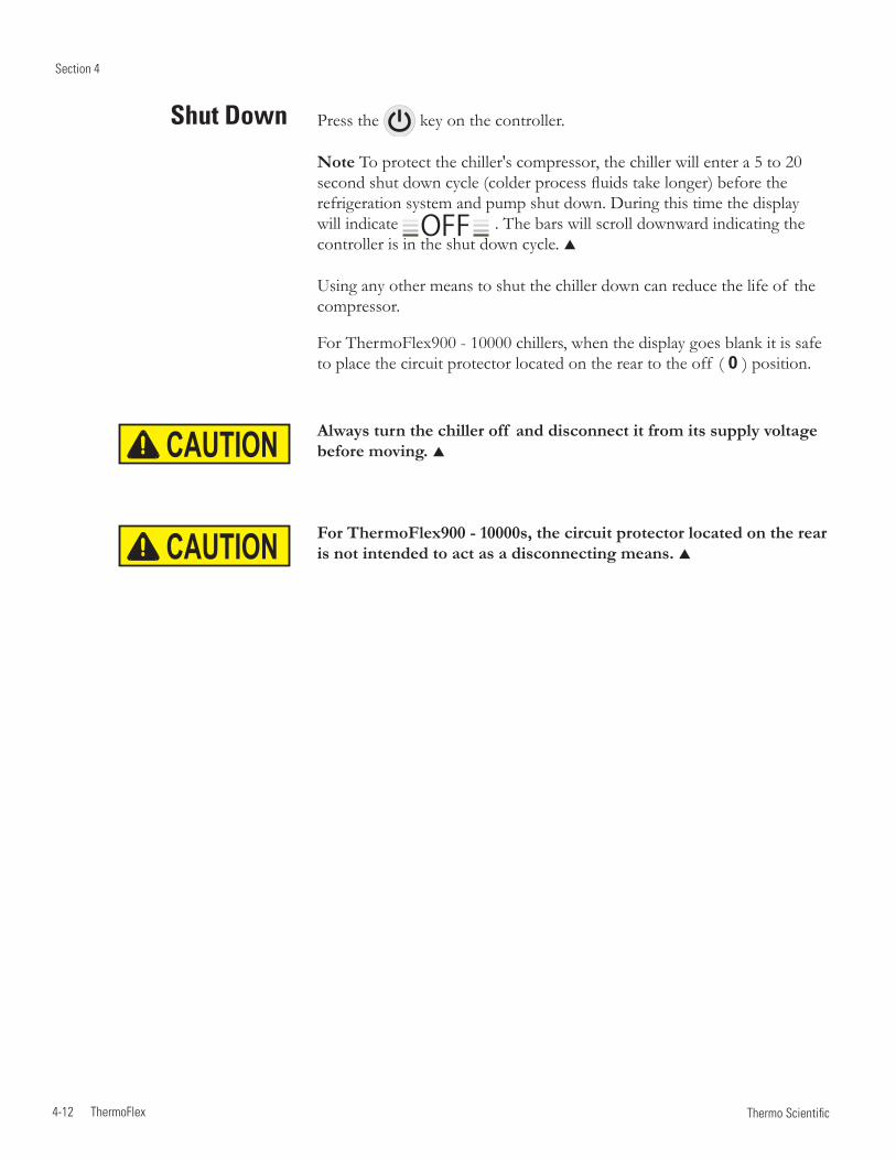
Section 4
4-12 ThermoFlex Thermo Scientific
Shut Down Press the key on the controller.
Note To protect the chiller's compressor, the chiller will enter a 5 to 20 second shut down cycle (colder process fluids take longer) before the refrigeration system and pump shut down. During this time the display will indicate OFF . The bars will scroll downward indicating the controller is in the shut down cycle.
Using any other means to shut the chiller down can reduce the life of the compressor.
For ThermoFlex900 - 10000 chillers, when the display goes blank it is safe to place the circuit protector located on the rear to the off ( 0 ) position.
Always turn the chiller off and disconnect it from its supply voltage before moving.
For ThermoFlex900 - 10000s, the circuit protector located on the rear is not intended to act as a disconnecting means.
CAUTION
CAUTION

ThermoFlex 5-1 Thermo Scientific
Auto Refill
The auto refill fluid must also meet water quality standards or the valve may fail to operate as designed, see Section 3.
The auto refill valve input pressure must be < 80 PSI to ensure the valve functions properly.
The auto refill operates when all of the following conditions are met: • Fluid is available • The chiller is turned on • The fluid reaches a low level condition.
The auto refill shuts off when:• The fluid reaches the correct operating level.• The delay timer exceeds user fill time entered in the Setup Loop, see
Section 4. If FLt is selected in the Setup Loop the chiller also shuts down. (If indC is selected the chiller continues to run.) In either case the controller will display rEFIL.
• The chiller shuts down for any reason.
Setting the fill time to 0 disables auto refill. If a low level condition occurs the chiller will: • If Indc is selected, continue to run and the controller displays Add. • If FLt is selected, shut down and the controller displays LLF.
Figure 5-1 Auto Refill Fitting
Section 5 Options/AccessoriesThe Auto Refill provides makeup fluid to replace any fluid lost to evaporation, etc. It requires a pressurized fluid source connection to the ¼" Female Pipe Thread fitting on the rear of the chiller. (If Teflon® tape is used, ensure the tape does not cover the connection's starting-end thread.)
Note ThermoFlex7500 through 24000s with a P3 or P5 pump have a ¼" Male brass plug installed in the connection, remove the plug before connecting the makeup fluid.

Section 5
5-2 ThermoFlex Thermo Scientific
A partial flow DI filter cartridge is designed to maintain water resistivity between 1 and 3 MΩ-cm.
Note The DI option results in a 0.5 gpm reduction of available flow.
Do not use a Deionization (DI) filter cartridge with Inhibited EG or Inhibited PG. A DI filter will remove inhibitors from the solution ren-dering the fluid ineffective against corrosion protection. Also, inhibi-tors increase fluid conductivity.
The Puralite sensor on the back of the chiller turns red when the cartridge needs changing (< 1 MΩ-cm), see Section 6. Note The Puralite sensor that comes with the DI cartridge requires a separate power source.
Remove the two thumbscrews securing the DI access panel. Remove the new cartridge from the shipping bag. The cartridge has a blue and a white connector. Lower the cartridge into the chiller with the blue connector facing downward. Press down on the cartridge lightly to engage and then rotate it ¼ turn clockwise (do not over rotate) or until you feel the filter click into place.
If there is a cartridge in place, first undo the hose fitting by pressing on the quick disconnect located on the top white connection.
The DI Cartridge will overpressurize if it is removed from the chiller before removing the hose fitting.
Next rotate the cartridge ¼ turn counter-clockwise and then pull the cartridge straight up to remove it.
Push the hose fitting into the quick disconnect located on the white end of the cartridge.
Replace the access panel and thumbscrews.
Note The cartridge can be changed with the chiller running, however, since the cartridge
runs in a parallel arrangement, disconnecting the cartridge adds 0.5 gpm to the main flow. The additional flow will cause an increase in system pressure which may cause a high fluid pressure fault.
Internal DI Cartridge
Quick Disconnect
Hose Fitting
Figure 5-3 DI Fittings
Figure 5-2 Internal DI Cartridge
Blue Connector
White Connector
Access Panel
CAUTION
CAUTION

Section 5
ThermoFlex 5-3 Thermo Scientific
P 1 P 2 T 0 T 1 Pump Pressure Relief Valve
(Internal Configuration)
Figure 5-5 Main Loop
Use the pressure relief valve, located on the top left rear of the chiller, to set the desired system back pressure to your application. The valve is factory preset to 80 ± 5 psi (5.5 ± 0.4 bar).
If the chiller is not plumbed to an application, set the pressure by installing a loop of hose equipped with a shut-off valve between the supply and return fittings. Start the chiller and allow it to prime, then close the valve.
Use the controller's to display P 1, it should display 80 ± 5 psi.
Adjusting ScrewPacking Nut
Use a screwdriver to turn the adjusting screw (counterclockwise to reduce pressure) until the controller displays the desired setting.
Note Due to internal back pressure, the minimum pressure setting for a deadheaded P 2 pump is 32 psi (2.2 bar), and 8 psi (0.6 bar) for a P 1 (these settings prohibit external flow from the chiller).
If the chiller is plumbed to an application, ensure the chiller is off. Then back out the adjusting screw counterclockwise to reduce pressure. Turn the chiller on. Ensure that there is back pressure in the system. Turn the adjusting screw until the controller displays the desired setting.
Do not exceed 100 psi (6.9 bar).
When complete, inspect the area around the 5/8" packing nut for fluid leaks. If fluid is present, slightly tighten the nut and reinspect.
Note Should the chiller start to vibrate the valve setting may be the cause. Changing the pressure setting ± 5 psi (0.3 bar) will eliminate the vibration.
Figure 5-4 Nut and Screw
P1
FLo
xx.x C
80
xx
- +
PSI/KPa
CAUTION

Section 5
5-4 ThermoFlex Thermo Scientific
Figure 5-7 Main Loop
P 1 P 2 T 0 T 1 Pump Pressure Relief Valve (External Configuration)
Use the pressure relief valve to set the desired system back pressure (P1) to your application. The valve is factory preset to 80 ± 5 psi (5.5 ± 0.4 bar).
The valve's inlet/outlet connections are ½"FNPT.
If the chiller is not plumbed to an application, set the pressure by installing a loop of hose equipped with a shut-off valve between the supply and return fittings. Start the chiller and allow it to prime, then close the valve.
Use the controller's to display P 1, it should display 80 ± 5 psi.
Packing Nut
Adjusting Screw
Figure 5-6 Nut and Screw
Use a screwdriver to turn the adjusting screw (counterclockwise to reduce pressure) until the controller displays the desired setting.
Note Due to internal back pressure, the minimum pressure setting for a deadheaded P 2 pump is 40 psi (2.8 bar), and 22 psi (1.5 bar) for a P 1 (these settings prohibit external flow from the chiller).
If the chiller is plumbed to an application, ensure the chiller is off. Then back out the adjusting screw counterclockwise to reduce pressure. Turn the chiller on. Ensure that there is back pressure in the system. Turn the adjusting screw until the controller displays the desired setting.
Do not exceed 100 psi (6.9 bar).
When complete, inspect the area around the 5/8" packing nut for fluid leaks. If fluid is present, slightly tighten the nut and reinspect.
P1
FLo
xx.x C
80
xx
- +
PSI/KPa
CAUTION

Section 5
ThermoFlex 5-5 Thermo Scientific
Flow Control with Flow Readout
P 1 P 2 T 0 T 1 Pump Pressure Relief with
Flow Readout
Figure 5-8 Flow Control
Figure 5-9 Flow Control Handle (Typical)
Figure 5-10 Pressure Relief
Auxillary Process Outlet
DrainPlug
Valve Handle
Flow control for P 1, P 2 T0 and T 1 pumps on ThermoFlex900 - 5000s is achieved using a 3-way valve plumbed between the standard process outlet and the process inlet on the rear of the chiller. Use the auxiliary process outlet at the top left of the rear of the chiller as a connection point. The connections are ½" FNPT. See Figure 5-8.
ThermoFlex3500 and 5000s with P 3 and P 4 pumps use a 2-way valve located on the rear of the chiller. The connections are 3/4" FNPT. See Figure 5-9.
ThermoFlex7500 and 24000s with P 2 - P 5 and T 5 pumps use a valve located on the rear of the chiller. The connections are 1/2" FNPT for P 2, 1" FNPT for P 3 and P 5. See Figure 5-9.
Press the controller's down arrow twice to display the controller's FLo display, see previous page. Turn the valve handle until the desired rate is displayed.
Note The valve is sensitive to slight adjustments.
Auxiliary Process Outlet
Process Inlet
Process Inlet
The Pressure Relief with Flow Readout works just like the Pressure Relief Valve discussed on the previous page. It allows you to control the pressure going to your application.
This valve is plumbed between the standard process outlet and the process inlet on the rear of the chiller. Use the auxiliary process outlet at the top left of the rear of the chiller as a connection point, allowing you to also monitor the flow rate to your application using the controller's FLo display, see previous page.
The valve's outlet connection is ½" FNPT. See Figure 5-10.

Section 5
5-6 ThermoFlex Thermo Scientific
ComplianceSEMI chillers are compliant with: SEMI S2-0703 Product Safety Assessment SEMI S8-0705 Ergonomic Assessment SEMI S14-0704 Fire Risk Assessment SEMI F47-0706
Emergency Off (EMO) A guarded red mushroom shaped push-button switch with twist-to-reset is provided on the chiller's front to turn it off in case of an emergency. The button head is engraved with “EMO” in large white filled letters.
Note The EMO is controlled by a safety circuit and is not influenced by the chiller's firmware/software.
Activation of the EMO button will remove power from the main contactor coil stopping operation of the chiller. The controller will display Er 48.
Resetting the EMO button will not restart the chiller. After all hazards have been removed reset the chiller by pushing the enter key on the controller. In the local mode, the chiller will restart by pressing the START STOP button again. In the serial communications mode, send the appropriate start command. In the analog I/O mode, the chiller starts when the error is cleared.
Chiller Circuit Breaker Interrupt Rating The main power circuit breaker located on the rear of the chiller has an Interrupting Capacity (AIC) of 10,000 amps.
Semiconductor Equipment and
Materials International
(SEMI) Chillers
(ThermoFlex900-10000 only)
Chillers installed below the end-user application may allow system fluid to drain back into the chiller and cause spillage. The anti-drainback valve is designed to prevent any such spillage.
The valve opens just before the pump is turned on and it closes just after the pump shuts off.
This option is required if your chiller is more than 24 feet below your application, or if there is a possibility of drain back due to the occasional opening of the process lines for either application swaps or chiller servicing.
Anti Drainback

Section 5
ThermoFlex 5-7 Thermo Scientific
A
B
1/4 Turn Quick Disconnect Drip Pan Drain Fitting
C
Barb for 1/2" ID Hose
900/1400 2500 3500/5000 7500/10000
A 3 1/2" 8.8 cm 4" 10.1 cm 3 3/8" 11.3 cm 4 1/4" 10.8 cm
B 2 3/4 " 7.0 cm 2 11/16" 6.8 cm 2 3/4" 7.1 cm 2 5/8" 6.6 cm
C 6 15/16" 17.7 cm 6 9/16" 16.7 cm 9 9/16" 24.3 cm 7 11/16" 19.5 cm
Figure 5-11 Drip Pan Drain
Seismic Tie-down (typical)
Lockout/Tagout (LOTO) Before performing Chiller maintenance, the energy sources associated with the Chiller system must be lockedout and tagged out (LOTO). Hazard control features added to the system (e.g., safety interlocks, EMO) are not a substitute for turning off and locking out electrical or fluid energy.
For chillers rated 20 Amps or less, electrical LOTO is accomplished by removing the power cord on the rear of the chiller then closing and locking the power receptacle locking device. For other chillers, electrical LOTO is the responsibility of the user and can be provided by:
• Using the main disconnect (knife switch at system control cabinet). • Disconnecting main power at the facility power source prior to the system controller cabinet. • In addition, follow all OSHA and local facility LOTO directives.
Drip Pan and Drain The chiller is equipped with a secondary containment (drip pan) in case there is a leak. The drip pan drain is located on the rear of the chiller. Install the supplied nylon 1/4 turn quick disconnect (QD) fitting into the drain fitting. The QD is barbed for a 1/2" ID hose.
Since the drip pan will not hold more than 110% of the reservoir volume, connect the drain to guide the fluid to an appropriate spillage location.

Section 5
5-8 ThermoFlex Thermo Scientific
D
AB
C
Front ViewSide View
900/1400 2500 3500/5000 7500/10000
A 2 11/16" 6.8 cm 2 11/16" 6.8 cm 2 11/16" 6.8 cm 2" 5.1 cm
B* 18 ½ " 47.0 cm 20 1/16" 51.0 cm 24 ½" 62.2 cm 17" 43.1 cm
C* 19 11/16" 50.0 cm 22 3/4" 57.8 cm 24 3/4" 62.9 cm 27 7/16" 69.6
D 21 3/16" 53.8 cm 24 1/4" 61.5 cm 26 1/4" 66.7 cm 28 15/16" 73.4
* Distance between Ø.53 Seismic mounting holes
Figure 5-12 Seismic Tie-Downs
5/16" Bolt
5/16" Nut
5/16" Washer
5/16" Washers
Seismic Tie-Downs Install the seismic tie-downs to the chiller as shown below. Then secure the chiller to the floor with user-supplied hardware.
Seismic Tie-down (typical)

Section 5
ThermoFlex 5-9 Thermo Scientific
Center of Gravity ± ½", air-cooled chiller, no fluid in tank
Center of Gravity ± ½", water-cooled chiller, no fluid in tank
Top View
A
AB
C
Side View
Figure 5-13 Center of Gravity
900/1400 P2 Pump 2500 P2 Pump 3500/5000 P2 Pump 7500/10000 P3 Pump
A 10 3/4 " 27.3 cm 12" 30.5 cm 13 3/8" 34.0 cm 14 7/8" 37.8 cm
B 6 3/4" 17.2 cm 8 3/8" 21.3 cm 9" 22.9 cm 13 1/8" 33.3 cm
C 13 1/2" 34.3 cm 13 1/2" 34.3 cm 17" 43.2 cm 26" 66.0 cm
20000 P3 Pump 24000 P3 Pump 5000 P4 Pump Global Voltage
A 13 3/4 " 34.9 cm 12" 30.5 cm 12 3/8" 31.4 cm
B 21 5/8" 54.9 cm 8 3/8" 21.3 cm 9 3/4" 24.8 cm
C 21 1/4" 54.0 cm 13 1/2" 34.3 cm 19 1/2" 49.5 cm
5000 P2 Pump 20000 P3 Pump 24000 P3 Pump
A 13" 33.0 cm 17" 43.2 cm 12" 30.5 cm
B 9 1/2" 24.1 cm 22" 55.9 cm 23" 58.4 cm
C 16" 40.6 cm 20 1/2" 52.1 cm 21" 53.3 cm
900/1400 P2 2500 P2 3500/5000 P2 7500/10000 P3
Left Front 27.1 lbs 12.3 kg 40.7 lbs 18.5 kg 62.0 lbs 28.1 kg 97.8 lbs 44.4 kg
Left Rear 29.8 lbs 13.5 kg 42.0 lbs 19.1 kg 63.7 lbs 28.9 kg 99.9 lbs 45.3 kg
Right Front 32.9 lbs 14.9 kg 45.7 lbs 20.7 kg 68.2 lbs 30.9 kg 89.2 lbs 40.5 kg
Right Rear 36.2 lbs 16.4 kg 47.1 lbs 21.4 kg 70.0 lbs 31.8 kg 91.1 lbs 41.3 kg
Center of Gravity
Weight Distribution ± 2 lbs, air-cooled chillers

Section 5
5-10 ThermoFlex Thermo Scientific
Installation kit - includes replacement air and fluid filters
Maintenance kit - includes a set of hoses, adaptor fittings and Teflon® tape
Fluids
Fluid treatment kit
Please contact Thermo Fisher Scientific's Sales, Service and Customer Support to assist you with questions that you may have regarding accessories for your ThermoFlex, see inside front cover for contact information.
Other Accessories

ThermoFlex 6-1 Thermo Scientific
Section 6 Preventive Maintenance
Only Thermo Fisher should provide any required replacement parts.
The ThermoFlex chiller has an integrated preventive maintenance timer that will alert you when it is time to perform preventive maintenance. This unique feature will remind you to change your air and fluid filters.
Based on the environment in which your chiller is located, you can choose from four levels of preventive maintenance off, L1, L2, and L3:
• off – Disables the alert • L1 – 1,000 hours - default setting · Heavy manufacturing environment · Airborne particulate created during manufacturing process • L2 – 2,000 hours · Typical production environment • L3 – 3,000 hours · Clean environment – filtered air · Typically laboratory or research environment
Change/set the level using the Setup Loop, see Section 4. When the chiller exceeds the chosen limit, the controller will flash and, if enabled, an audible alarm will sound.
To clear this message press . This will automatically restart the preventive maintenance timer for your filters. Each time the chiller exceeds the chosen time, the controller will remind you that it is time to change your filters.
If you change your filters before the preventive timer trips, you can clear the timer by using the Diagnostic Loop explained in this Section.
Note For air-cooled chillers, both the air and fluid filters in the ThermoFlex can be changed while the chiller is running. For water-cooled chillers, only the fluid filter can be changed while the chiller is running.
Preventive Maintenance Timer
( )

6-2 ThermoFlex
Section 6
Thermo Scientific
The reservoir has a fluid bag filter designed to prevent the introduction of particulates into the system. Chillers are shipped with a bag filter in place.
Note The fluid bag filter can be removed with the chiller operating.
Before using any fluid or performing maintenance where contact with the fluid is likely refer to the manufacturer’s MSDS for handling precautions.
Fluid Filter Bag
Before replacing the reservoir housing ensure the reservoir sight tube ball stopper is securely in place, see next page.
On ThermoFlex900-5000s, when you remove the bag you will notice a wire mesh fluid diffuser inside the reservoir supply line, see Figure 6-2. The diffuser is used to help streamline the flow into the reservoir. After several bag replacements turn the chiller off and remove the diffuser to inspect it for debris/damage.
The fluid velocity into the reservoir will rapidly increase with the diffuser removed and cause splashing. Turn the chiller off before removing the diffuser. This is especially critical when using ethylene or propylene glycol.
Note To prevent particulates from entering the reservoir, ensure the fluid bag filter is in place before removing the diffuser.
Do not operate the chiller unless the diffuser is installed.
Fluid Bag Filter
Figure 6-1 Fluid Filter Bag
Funnel Housing
Fluid Diffuser
WARNING
WARNING
CAUTION
CAUTION
When it is time to replace the bag, gently pull up on the plastic funnel housing to remove it and simply pull the bag out of the chiller. Replacement bags are available from Thermo Fisher Scientific.

Section 6
ThermoFlex 6-3 Thermo Scientific
Reservoir Cleaning
The user is responsible for maintaining reservoir fluid quality. Check the fluid on a regular interval. Start with frequent checks until a regular interval (based on your application) is established.
If cleaning is necessary, flush the reservoir with a fluid compatible with the process fluid and the chiller's wetted parts, see Section 8.
Before using any fluid or performing maintenance where contact with the fluid is likely refer to the manufacturer’s MSDS for handling precautions.
Reservoir Sight Tube Clean the sight tube by gently pulling up on the plastic funnel housing to remove it (see illustration on previous page) and then gently pulling out the black sight ball stopper from the tube. Use a long soft-bristle ¼" brush. Use caution not to scratch the glass.
Before replacing the reservoir housing ensure the reservoir sight tube ball stopper is securely in place.
For easier replacement, wet the stopper first and then use a twisting motion to install it in the sight tube.
Wire Mesh Fluid Diffuser(ThermoFlex900-5000)
Sight Tube
Ball Stopper
Figure 6-2 Reservoir Cleaning and Diffuser
An effective recommended maintenance plan would include changing the fluid every six months to optimize chiller reliability, see Section 3 for additional information.
Fluid Maintenance
WARNING
CAUTION

6-4 ThermoFlex
Section 6
Thermo Scientific
Condenser Filter
Failure to clean/replace the condenser filter will cause a loss of cooling capacity and lead to premature failure of the cooling system.
ThermoFlex900 - 5000 Clean the filter through the grill using a vacuum with a soft-bristle brush.
When it is time for a more thorough cleaning, remove the one-piece grill assembly by first pulling the bottom of the assembly away from the chiller and then pulling it away from the top.
The condenser framing and fins located behind the grill assembly are very sharp. Use caution when removing the assembly.
Note ThermoFlex900 - 5000 water-cooled chillers have an embedded screw(s) located at the top (and bottom) of the grill. Loosen the screw(s) to remove the grill.
Water-cooled chillers also have a fan with sharp blades, ensure the chiller is off before removing the assembly.
Shake off as much of the excess water as possible before reinstalling. Press the grill back into place.
For water-cooled chillers, tighten the screw(s) at the top (and bottom) of the grill.
Replacement grill assemblies are available from Thermo Fisher.
Screw (Water-cooled chillers)
CAUTION - Sharp edges
Figure 6-3 ThermoFlex900 - 5000 Condenser Grill Removal
ThermoFlex3500 - 5000 water-cooled chillers have two screws securing the condenser. One screw on the top and one on the bottom.
WARNING
WARNING
CAUTION

Section 6
ThermoFlex 6-5 Thermo Scientific
Chiller Surface
Hoses
ThermoFlex7500 - 10000 For air-cooled chillers, remove the one-piece grill assembly by pulling the assembly away from the chiller.
Water-cooled chillers do not have a filter.
The filter goes over four studs and plastic "fast nuts" hold it in place.
Replace it or vacuum the old filter with a soft-bristle brush, or wash it. Shake off as much of the excess water as possible before reinstalling.
Tuck the filter around the perimeter of the grill and over the four studs, use the plastic "fast nuts" to hold it in place.
Replacement grills are available from Thermo Fisher.
Figure 6-4 Filter Removal/Replacement ThermoFlex7500 - 10000 Air-Cooled
"fast nut"
Clean the chiller's surface with a soft cloth and warm water only.
Inspect he chiller's external hoses and clamps on a regular basis.
ThermoFlex15000 - 24000 The air-cooled chillers do not have filters but the condenser fins can be cleaned by removing the eight screws securing the lower-front panel.

6-6 ThermoFlex
Section 6
Thermo Scientific
DI Filter (Optional) Establish a preventive maintenance schedule for the DI filter cartridge based on your specific application.
The Puralite sensor located on the back of your chiller will illuminate red when it is time to change the DI filter cartridge (< 1 MΩ-cm).
Note When the chiller is initially powered, or has been sitting idle for a period of time, the sensor may illuminate. The length of time it will be on varies with your application.
Although the Puralite sensor is the primary indicator that the cartridge needs changing, the chiller also has a separate integrated alarm that works independently of the Puralite. The alarm is based on chiller run hours that will alert you when it is time to change your filter. The di t alarm is enabled using the Setup Loop, see Section 4.
If you already know how often your DI filter needs changing, you can input the number of hours into the Setup Loop's di t display. When the time is reached, the controller will flash di and the audible alarm, if enabled, will sound.
When alerted, check the Puralite sensor to see if it is illuminated. If it is not illuminated reset the di t timer and then check the Puralite periodically.
To clear this message and stop the audible alarm press .
If the Puralite has turned red and the controller alarm has not gone off, access the Diagnostic Loop di display, see next page. Check the system run hours, this will give you an accurate DI replacement time. Adjust the di t filter alarm to match the time needed between filter cartridge changes.
This will automatically restart the preventive maintenance timer for your DI filter. If you change the filter before the preventive maintenance timer alerts you, you can clear the timer by again accessing the Diagnostic Loop di display, see next page.
Note It may be necessary to monitor the Puralite three or four times to establish an accurate changing schedule. Also, filter operating time is reduced every time new fluid is added.
Figure 6-5 Puralite

Section 6
ThermoFlex 6-7 Thermo Scientific
The Diagnostic Loop is used to view or reset the operating times of various chiller components.
To enter the Diagnostic Loop ensure the controller display is either a blank screen (chiller off) or displaying the process fluid temperature.
Press the key and the display will indicate SP, press again to display SEtuP, press again to display .
Press to enter the loop or press to return to the process fluid temperature or blank display.
Use the key to sequence down through the loop. Use the key to sequence up through the loop.
Figure 6-6 Diagnostic Loop
Diagnostic Loop ( )
FLtrS xxxx
xxxx
xxxx
di
unit
SP SEtuP
enter
mode mode mode mode
xx.x Cor
FLtrS - Indicates the total hours the air and fluid filters have been in use. If desired, press and hold and then press to reset the value to 0.
di - Indicates the total hours the optional di filter cartridge has been in use. If desired, press and hold and then press to reset the value to 0.
unit - Indicates the chiller operating hours. This value can not be reset.
Testing the Safety Features
For chillers equipped with auto refill switch we recommend slowly draining the reservoir and ensure the auto refill activates.

6-8 ThermoFlex
Section 6
Thermo Scientific

Ther
mo
Sci
entifi
c
The
rmoF
lex
7-
1
Erro
r Cod
esT
he c
ontro
ller c
an d
isplay
Err
or C
odes
. If
the
chill
er is
still
runn
ing
pres
s ent
er to
see
if th
e co
de c
lear
s, a
limit
may
hav
e be
en o
nly
tem
pora
rily
exce
eded
. If
the
chill
er sh
ut d
own,
the
cont
rolle
r will
con
tinue
to fl
ash
the
erro
r cod
e. Pr
ess e
nter
to c
lear
the
disp
lay a
nd si
lenc
e an
y al
arm
. You
ca
n sil
ence
the
alar
m w
ithou
t cle
arin
g th
e co
de b
y pr
essin
g ei
ther
the
up o
r dow
n ar
row
key
. Onc
e th
e ca
use
of th
e sh
ut d
own
is id
entifi
ed a
nd
corr
ecte
d, st
art t
he c
hille
r. If
the
caus
e w
as n
ot c
orre
cted
the
erro
r cod
e w
ill re
appe
ar. C
onta
ct o
ur S
ales
, Ser
vice
and
Cus
tom
er S
uppo
rt.
Sect
ion
7 Tr
oubl
esho
otin
g
Err
or C
ode
Rea
ctio
nC
ause
Act
ions
8888
(or
blan
k sc
reen
)C
hille
r will
not
sta
rt.
Soft
war
e co
mm
unic
atio
n er
ror.
• Cyc
le c
ircui
t pro
tect
or o
n th
e re
ar o
f th
e ch
iller
, T
herm
oFle
x900
-100
00 o
nly.
Add
Chi
ller c
ontin
ues
to ru
n.A
uto
refil
l, if
inst
alle
d,
shut
s of
f.
The
aut
o re
fill t
ime
chos
en fo
r the
cu
stom
er a
djus
tabl
e fil
l set
ting
in th
e Se
tup
Loop
is s
et to
0 a
nd th
e ch
iller
is
confi
gure
d to
kee
p ru
nnin
g, s
ee
Sect
ion
4.
•Che
ck fo
r lea
ks.
•Che
ck rE
Fil s
ettin
gs a
nd a
djus
t if
nece
ssar
y, se
e Se
ctio
n 4.
• Add
flui
d to
the
tank
.di
Chi
ller c
ontin
ues
to ru
n.
(Opt
iona
l disp
lay)
The
chi
ller o
pera
ting
time
exce
eded
Se
tup
Loop
di t
ala
rm v
alue
. The
op
tiona
l DI c
artr
idge
may
nee
d re
plac
ing.
• Che
ck th
e Pu
ralit
e se
nsor
, see
Sec
tion
6. If
the
light
is
red
chan
ge th
e ca
rtrid
ge, s
ee S
ectio
n 5.
• If
the
Pura
lite
sens
or is
gre
en, s
ee S
ectio
n 4
to re
vise
di
t al
arm
val
ue.
driP
Chi
ller w
ill s
hut d
own.
(Opt
iona
l disp
lay)
Flui
d in
drip
pan
(SE
MI o
nly)
.•C
heck
for l
eaks
.
•Rem
ove
the
fluid
from
the
drip
pan
and
rese
t the
faul
t.FL
o-Lo
FLo
Chi
ller c
ontin
ues
to ru
n.T
he lo
w fl
ow a
larm
is s
et to
0.0
and
the
pum
p flo
w ra
te is
bel
ow th
e m
inim
um
requ
ired,
see
Sec
tion
4.
•See
LoF
Lo e
rror
cod
e.
FLtr
SC
hille
r con
tinue
s to
run.
Air
and
fluid
filte
rs re
quire
pre
vent
ive
mai
nten
ance
/rep
lace
men
t.• C
heck
air
and
fluid
filte
rs. I
f re
quire
d, c
lean
/cha
nge
air
and
fluid
filte
rs, s
ee S
ectio
n 6.
• If
your
filte
rs d
o no
t nee
d cl
eani
ng, y
ou m
ay in
crea
se
the
num
ber o
f ho
urs
betw
een
prev
entiv
e ca
re
rem
inde
rs. T
here
are
four
leve
ls, s
ee S
ectio
n 6.

The
rmo
Sci
entifi
c
Ther
moF
lex
7-2
Sec
tion
7
Err
or C
ode
Rea
ctio
nC
ause
Act
ions
HiF
LoC
hille
r rea
ctio
n de
pend
s on
ALr
set
ting
chos
en in
th
e Se
tup
Loop
, see
Sec
-tio
n 4.
(Chi
ller e
quip
ped
with
a fl
ow tr
ansd
ucer
.)
The
pro
cess
flui
d flo
w
rate
has
exc
eede
d th
e ad
just
able
hig
h flo
w
setti
ng’s
valu
e.
• If
the
chill
er is
stil
l run
ning
pre
ss e
nter
to s
ee if
the
code
cle
ars,
the
limit
may
hav
e be
en o
nly
tem
pora
rily
exce
eded
.
• Ver
ify y
our H
iFLo
set
ting,
see
Sec
tion
4, a
nd a
djus
t set
ting
if
nece
ssar
y.
• Che
ck a
ll ap
plic
atio
n an
d pl
umbi
ng s
hut o
ff v
alve
s fo
r cor
rect
po
sitio
n.
• Adj
ust fl
ow if
chi
ller i
s eq
uipp
ed w
ith a
n op
tiona
l flow
con
trol
val
ve,
see
Sect
ion
5.
• If
flow
tran
sduc
er w
as re
cent
ly c
alib
rate
d do
uble
che
ck c
alib
ratio
n, s
ee
Sect
ion
8.H
i P1
Chi
ller r
eact
ion
depe
nds
on A
Lr s
ettin
g ch
osen
in
the
Setu
p Lo
op, s
ee S
ec-
tion
4.
The
pum
p’s
high
di
scha
rge
pres
sure
ex
ceed
ed S
etup
Loo
p hi
gh a
larm
val
ue.
•If
the
chill
er is
stil
l run
ning
pre
ss e
nter
to s
ee if
the
code
cle
ars,
the
limit
may
hav
e be
en o
nly
tem
pora
rily
exce
eded
.
•Ver
ify y
our H
i P1
setti
ng, s
ee S
ectio
n 4.
• Che
ck a
pplic
atio
n va
lves
and
ens
ure
that
they
hav
e no
t cha
nged
or
clos
ed. N
ote
If ro
utin
e sh
ut-o
ff o
f th
e pr
oces
s flo
w is
requ
ired
then
an
ext
erna
l pre
ssur
e re
lief
valv
e sh
ould
be
adde
d, s
ee S
ectio
n 5.
•May
occ
ur a
s a
resu
lt of
cha
ngin
g th
e in
tern
al D
I car
trid
ge.
Disc
onne
ctin
g th
e ca
rtrid
ge a
dds
an a
dditi
onal
0.5
gpm
to th
e m
ain
flow.
See
Sec
tion
5.
•Che
ck fo
r deb
ris in
the
appl
icat
ion
or e
xter
nal fi
lters
.
• Dou
ble
chec
k flu
id li
nes.
Exc
essiv
e be
nds,
long
tubi
ng a
nd d
iam
eter
re
duct
ions
can
aff
ect t
he p
ump’
s di
scha
rge
pres
sure
. Not
e If
dia
met
er
redu
ctio
ns m
ust b
e m
ade,
they
sho
uld
be m
ade
at th
e in
let a
nd o
utle
t of
you
r app
licat
ion,
not
at t
he c
hille
r.

Ther
mo
Sci
entifi
c
The
rmoF
lex
7-
3
Sec
tion
7
Err
or C
ode
Rea
ctio
nC
ause
Act
ions
Hi t
Chi
ller r
eact
ion
depe
nds o
n A
Lr se
tting
cho
sen
in th
e Se
tup
Loop
, see
Sec
tion
4.N
ote
If th
e ch
iller
doe
s sh
ut d
own
it ca
n be
re
star
ted
prov
ided
the
tem
pera
ture
is st
ill w
ithin
th
e fa
ctor
y-se
t hig
h fix
ed
tem
pera
ture
lim
it. H
owev
er,
the
erro
r will
reoc
cur i
f th
e te
mpe
ratu
re g
oes b
elow
the
adju
stab
le se
tting
and
then
ag
ain
exce
eds i
t.
The
pro
cess
flui
d te
mpe
ratu
re e
xcee
ded
Setu
p Lo
op a
larm
val
ue.
•If t
he c
hille
r is s
till r
unni
ng p
ress
ent
er to
see
if th
e co
de c
lear
s, th
e lim
it m
ay h
ave
been
onl
y te
mpo
raril
y ex
ceed
ed.
•Ver
ify y
our H
i t se
tting
, see
Sec
tion
4.•E
nsur
e th
e ch
iller
mee
ts a
ll en
viro
nmen
tal r
equi
rem
ents,
see
Sect
ion
3.• C
lean
the
air fi
lter.
Dirt
and
deb
ris o
n th
e fil
ter c
an p
reve
nt th
e ch
iller
fr
om fu
nctio
ning
at f
ull c
apac
ity, s
ee S
ectio
n 6.
• Ens
ure
that
the
heat
load
bei
ng a
pplie
d to
the
chill
er is
not
too
high
. C
onta
ct T
herm
o Fi
sher
for a
ssist
ance
on
calc
ulat
ing
heat
load
s.•B
ring
cool
er a
ir in
from
ano
ther
are
a or
exh
aust
the
hot a
ir in
to a
noth
er
loca
tion
usin
g an
aux
iliar
y fa
n.•V
erify
/adj
ust c
ontro
ller P
ID v
alue
s, se
e th
e en
d of
this
sect
ion.
HPC
Chi
ller w
ill sh
ut d
own.
Hig
h re
frig
erat
ion
pres
sure
. A
ir-co
oled
chi
llers
• Ens
ure
that
the
ambi
ent t
empe
ratu
re is
not
exc
eedi
ng th
e re
com
men
ded
rang
e, se
e Se
ctio
n 3.
•Ens
ure
chill
er h
as a
dequ
ate
vent
ilatio
n, se
e Se
ctio
n 3.
• Cle
an th
e ai
r filte
r. D
irt a
nd d
ebris
on
the
filte
r can
pre
vent
the
filte
r fr
om fu
nctio
ning
at f
ull c
apac
ity, s
ee S
ectio
n 6.
•Brin
g co
oler
air
in fr
om a
noth
er a
rea
or e
xhau
st th
e ho
t air
into
ano
ther
lo
catio
n us
ing
an a
uxili
ary
fan.
Wat
er-c
oole
d ch
iller
s•E
nsur
e th
e pl
astic
plu
gs w
ere
rem
oved
from
the
faci
lity
conn
ectio
ns.
•Ens
ure
faci
lity
wat
er is
on
and
conn
ecte
d.
•Che
ck fa
cilit
y w
ater
flow
rate
and
pre
ssur
e.

The
rmo
Sci
entifi
c
Ther
moF
lex
7-4
Sec
tion
7
Err
or C
ode
Rea
ctio
nC
ause
Act
ions
LLF
Chi
ller w
ill sh
ut d
own.
Opt
iona
l aut
o re
fill s
huts
do
wn.
Rese
rvoi
r flui
d le
vel t
oo lo
w
for n
orm
al o
pera
tion.
The
aut
o re
fill t
ime
chos
en
for t
he c
usto
mer
adj
usta
ble
fill s
ettin
g in
the
Setu
p Lo
op
is se
t to
0 an
d th
e ch
iller
is
confi
gure
d to
shut
dow
n, se
e Se
ctio
n 4
•Exc
essiv
e ev
apor
atio
n. E
nsur
e th
e ch
iller
is o
pera
ting
with
the
fu
nnel
and
cap
in p
lace
.
•Che
ck fo
r lea
ks.
•Che
ck rE
Fil s
ettin
gs a
nd a
djus
t if
nece
ssar
y, se
e Se
ctio
n 4.
• Add
flui
d to
the
tank
.
LoFL
oC
hille
r rea
ctio
n de
pend
s on
ALr
setti
ng c
hose
n in
the
Setu
p Lo
op, s
ee S
ectio
n 4.
(Chi
llers
equ
ippe
d w
ith a
flow
tra
nsdu
cer.)
The
pro
cess
flui
d flo
w
rate
has
gon
e be
low
the
adju
stab
le se
tting
’s va
lue.
•If
the
chill
er is
still
runn
ing
pres
s ent
er to
see
if th
e co
de c
lear
s, th
e lim
it m
ay h
ave
been
onl
y te
mpo
raril
y ex
ceed
ed.
•Ver
ify y
our L
oFLo
setti
ng, s
ee S
ectio
n 4.
•Adj
ust fl
ow if
chi
ller i
s equ
ippe
d w
ith a
n op
tiona
l flow
con
trol
valv
e, se
e Se
ctio
n 5.
• Che
ck a
ll va
lves
in y
our a
pplic
atio
n an
d pl
umbi
ng li
nes t
o en
sure
th
at th
ey h
ave
not c
hang
ed o
r clo
sed.
•I
f flo
w tr
ansd
ucer
has
rece
ntly
bee
n ca
libra
ted,
dou
ble
chec
k ca
libra
tion
to e
nsur
e it
was
don
e pr
oper
ly, se
e Se
ctio
n 8.
Lo P
1C
hille
r rea
ctio
n de
pend
s on
ALr
setti
ng c
hose
n in
the
Setu
p Lo
op, s
ee S
ectio
n 4.
Pum
p’s l
ow d
ischa
rge
pres
sure
is b
elow
Set
up L
oop
low
ala
rm v
alue
.
•If
the
chill
er is
still
runn
ing
pres
s ent
er to
see
if th
e co
de c
lear
s, th
e lim
it m
ay h
ave
been
onl
y te
mpo
raril
y ex
ceed
ed.
•Ens
ure
that
chi
ller r
eser
voir
leve
l is n
ot to
o lo
w.
•Ver
ify y
our L
oP1
setti
ng, s
ee S
ectio
n 4.
• Chi
ller r
equi
res >
3 PS
IG a
pplic
atio
n pr
essu
re d
rop.
If a
byp
ass
valv
e ha
s bee
n in
stal
led,
som
e re
stric
tion
may
nee
d to
be
adde
d to
th
e by
pass
line
.

Ther
mo
Sci
entifi
c
The
rmoF
lex
7-
5
Sec
tion
7
Err
or C
ode
Rea
ctio
nC
ause
Act
ions
Lo t
Chi
ller r
eact
ion
de-
pend
s on
ALr
setti
ng
chos
en in
the
Setu
p Lo
op, s
ee S
ectio
n 4.
Not
e If
the
chill
er
does
shut
dow
n it
can
be re
star
ted
prov
ided
th
e te
mpe
ratu
re is
still
ab
ove
the
fact
ory-
set
low
fixe
d te
mpe
ratu
re
limit.
How
ever
, the
er
ror w
ill re
occu
r if
the
tem
pera
ture
goe
s ab
ove
the
adju
stab
le
setti
ng a
nd th
en a
gain
dr
ops b
elow
it.
Proc
ess fl
uid
tem
pera
ture
is
belo
w S
etup
Loo
p al
arm
val
ue.
•If
the
chill
er is
still
runn
ing
pres
s ent
er to
see
if th
e co
de c
lear
s, th
e lim
it m
ay h
ave
been
onl
y te
mpo
raril
y ex
ceed
ed.
•Ver
ify y
our L
o t s
ettin
g, se
e Se
ctio
n 4.
• Ens
ure
that
the
ambi
ent t
empe
ratu
re is
not
bel
ow th
e re
com
men
ded
low
-ran
ge, s
ee S
ectio
n 3.
If y
our a
pplic
atio
n lo
ad is
con
stan
t and
/or
the
low
er te
mpe
ratu
re c
an b
e te
mpo
raril
y to
lera
ted,
then
con
tinue
op
erat
ion.
(The
The
rmoF
lex
will
con
trol s
etpo
int w
hen
suffi
cien
t hea
t is
adde
d.)
•Ver
ify/a
djus
t con
trolle
r PID
val
ues.
• Add
insu
latio
n to
ext
erna
l plu
mbi
ng li
nes t
o re
duce
the
heat
-loss
to th
e en
viro
nmen
t.•F
or w
ater
-coo
led
chill
ers c
heck
faci
lity
wat
er te
mpe
ratu
re.
o FL
oC
hille
r will
shut
do
wn.
The
re is
an
over
flow
con
ditio
n in
the
rese
rvoi
r.•E
nsur
e th
e re
serv
oir w
as n
ot fi
lled
abov
e th
e M
AX
LE
VE
L lin
e.
•Che
ck fo
r clo
gged
rese
rvoi
r filte
r.oL
Chi
ller w
ill sh
ut
dow
n.
(Chi
llers
equ
ippe
d w
ith 3
-Ф p
ump
mot
or o
verlo
ad.)
Pum
p m
otor
ove
rload
act
ivat
ed.
Pum
p m
otor
exp
osed
to
exce
ssiv
e cu
rren
t due
to h
igh
pres
sure
, flow
or a
mbi
ent
tem
pera
ture
.
•Allo
w p
ump
to c
ool d
own.
oL 2
Chi
ller w
ill sh
ut
dow
n.
(Chi
llers
equ
ippe
d w
ith 3
-Ф fa
n.)
Fan
mot
or o
verlo
ad a
ctiv
ated
.•A
llow
chi
ller t
o co
ol d
own.
•For
air-
cool
ed c
hille
rs, c
lean
the
air fi
lter
PHEr
Chi
ller w
ill sh
ut
dow
n. (3
-Ф c
hille
r on
ly)
Phas
e ro
tatio
n is
wro
ng.
• Disc
onne
ct c
hille
r fro
m p
ower
sour
ce a
nd re
vers
e an
y tw
o lin
e co
nduc
tors
on
the
line
side
of th
e m
ain
circ
uit b
reak
er.

The
rmo
Sci
entifi
c
Ther
moF
lex
7-6
Sec
tion
7
Err
or C
ode
Rea
ctio
nC
ause
Act
ions
rEFi
LA
uto
refil
l will
shut
off.
Chi
ller r
eact
ion
depe
nds
on A
Lr se
tting
cho
sen
in
the
Setu
p Lo
op, s
ee S
ec-
tion
4.
Aut
o re
fill w
ill sh
ut o
ff.C
hille
r will
con
tinue
to
run.
(Opt
iona
l disp
lay.)
The
flui
d le
vel d
id n
ot re
ach
the
min
imum
ope
ratin
g le
vel
with
in th
e tim
e ch
osen
for t
he
cust
omer
adj
usta
ble
fill s
ettin
g,
chos
en in
the
Setu
p Lo
op, s
ee
Sect
ion
4.
The
aut
o re
fill s
ucce
ssfu
lly fi
lled
with
in th
e tim
e fr
ame
chos
en
for t
he c
usto
mer
adj
usta
ble
fill
setti
ng, b
ut th
e ch
iller
trie
d to
re
fill 5
tim
es in
40
hour
s.
•Che
ck a
uto
refil
l con
nect
ion.
•Che
ck fo
r lea
ks.
• Che
ck th
e su
pply
pre
ssur
e on
the
auto
refil
l sup
ply
line.
With
low
pr
essu
re th
e au
to re
fill t
ime
span
setti
ng m
ay b
e se
t too
low
and
th
e re
serv
oir d
oes n
ot h
ave
time
to fi
ll.
•Che
ck rE
Fil s
ettin
gs a
nd a
djus
t if
nece
ssar
y, se
e Se
ctio
n 4.
SEr 1
Chi
ller w
ill c
ontin
ue to
ru
n.Pe
riodi
c se
rvic
e m
ay b
e re
quire
d.•T
o cl
ear t
he m
essa
ge se
e Se
ctio
n 8.
Er 4
Chi
ller w
ill n
ot st
art.
Nor
mal
if n
ew so
ftwar
e in
stal
led
and
all v
alue
s in
the
Setu
p an
d Tu
ne L
oops
wer
e re
set t
o fa
ctor
y de
faul
ts.
•Cle
ar th
e er
ror c
ode.
Er 1
5C
hille
r will
con
tinue
to
run.
(Chi
ller e
quip
ped
with
se
rial c
omm
unic
atio
ns.)
Mom
enta
ry d
isrup
tion
of th
e in
tern
al c
omm
unic
atio
ns to
co
ntro
l boa
rd.
•Cle
ar th
e er
ror c
ode
Che
ck th
e se
rial c
omm
unic
atio
n co
nnec
tion.
•See
seria
l com
mun
icat
ion
conn
ectio
ns in
App
endi
x D
.
Er 1
6C
hille
r con
tinue
s to
run.
Bad
sens
or c
alib
ratio
n de
tect
ed
seve
ral s
econ
ds a
fter p
erfo
rmin
g a
calib
ratio
n.
•Red
o ca
libra
tion,
see
Sect
ion
8.

Ther
mo
Sci
entifi
c
The
rmoF
lex
7-
7
Sec
tion
7
Err
or
Cod
eR
eact
ion
Cau
seA
ctio
ns
Er 2
2T
his
erro
r cod
e ha
s pr
iorit
y ov
er H
iT.
Chi
ller w
ill s
hut d
own.
Not
e C
hille
r will
not
re
star
t unt
il pr
oces
s flu
id te
mpe
ratu
re is
be
low
+43
°C.
Rese
rvoi
r flui
d te
mpe
ratu
re
exce
eded
the
facto
ry p
reset
va
lue
of +
43°C
.
•Ens
ure
the
chill
er m
eets
all
envi
ronm
enta
l req
uire
men
ts, s
ee S
ectio
n 3.
• Cle
an th
e ai
r filte
r. D
irt a
nd d
ebris
on
the
filte
r can
pre
vent
the
chill
er fr
om fu
nctio
ning
at f
ull c
apac
ity, s
ee S
ectio
n 6.
• Ens
ure
that
the
heat
load
bei
ng a
pplie
d to
the
chill
er is
not
too
high
. C
onta
ct T
herm
o Fi
sher
for a
ssist
ance
on
calc
ulat
ing
heat
load
s.
•Brin
g co
oler
air
in fr
om a
noth
er a
rea
or e
xhau
st th
e ho
t air
into
an
othe
r loc
atio
n us
ing
an a
uxili
ary
fan.
•Ver
ify/a
djus
t con
trol
ler P
ID v
alue
s, se
e th
e en
d of
this
sect
ion.
Er 2
3C
hille
r will
shu
t dow
n.Re
frig
erat
ion
tem
pera
ture
se
nsor
sho
rted
.•C
onta
ct o
ur S
ales
, Ser
vice
and
Cus
tom
er S
uppo
rt.
Er 2
4C
hille
r will
shu
t dow
n.Re
frig
erat
ion
tem
pera
ture
se
nsor
ope
n.•C
onta
ct o
ur S
ales
, Ser
vice
and
Cus
tom
er S
uppo
rt.
Er 2
5C
hille
r will
shu
t dow
n.In
tern
al te
mpe
ratu
re s
enso
r sh
orte
d.•C
onta
ct o
ur S
ales
, Ser
vice
and
Cus
tom
er S
uppo
rt.
Er 2
6C
hille
r will
shu
t dow
n.In
tern
al te
mpe
ratu
re s
enso
r op
en.
•Con
tact
our
Sal
es, S
ervi
ce a
nd C
usto
mer
Sup
port
.
Er 2
8C
hille
r con
tinue
s to
ru
n.T
he p
roce
ss fl
uid
resis
tivity
ex
ceed
ed th
e lo
wer
adj
usta
ble
valu
e.
•Pre
ss e
nter
to s
ee if
the
code
cle
ars,
the
limit
may
hav
e be
en o
nly
tem
pora
rily
exce
eded
.
•Ver
ify c
ontr
olle
r’s s
ettin
gs, s
ee S
ectio
n 4
•Rep
lace
pro
cess
flui
d.Er
30
Chi
ller c
ontin
ues
to
run.
The
pro
cess
flui
d re
sistiv
ity
exce
eded
the
high
er
adju
stab
le v
alue
.
•Pre
ss e
nter
to s
ee if
the
code
cle
ars,
the
limit
may
hav
e be
en o
nly
tem
pora
rily
exce
eded
.
•Ver
ify c
ontr
olle
r’s s
ettin
gs, s
ee S
ectio
n 4
•Rep
lace
pro
cess
flui
d.Er
32
Chi
ller w
ill s
hut d
own.
Refr
iger
atio
n su
ctio
n ga
s te
mpe
ratu
re e
xcee
ded
50°C
.•M
ake
sure
supp
ly v
olta
ge m
atch
es th
e ch
iller
’s na
mep
late
ratin
g ±
10%
.

The
rmo
Sci
entifi
c
Ther
moF
lex
7-8
Sec
tion
7
Err
or C
ode
Rea
ctio
nC
ause
Act
ions
Er 3
3T
his e
rror
cod
e ha
s prio
rity
over
L o
T.
Chi
ller w
ill sh
ut d
own.
Not
e C
hille
r will
not
re
star
t unt
il pr
oces
s flui
d te
mpe
ratu
re e
xcee
ds +
2°C.
Rese
rvoi
r flui
d te
mpe
ratu
re
belo
w th
e fac
tory p
reset
valu
e of
+2°
C.
• Che
ck a
mbi
ent t
empe
ratu
re. C
hille
r may
not
to b
e ab
le to
reac
h se
tpoi
nt a
t low
am
bien
t tem
pera
ture
s.• E
nsur
e th
at th
e am
bien
t tem
pera
ture
is n
ot e
xcee
ding
the
reco
mm
ende
d ra
nge,
see
Sect
ion
3.•V
erify
/adj
ust c
ontro
ller P
ID v
alue
s, se
e Se
ctio
n 7.
• A
dd in
sula
tion
to e
xter
nal p
lum
bing
line
s to
redu
ce th
e he
at-lo
ss
to th
e en
viro
nmen
t.•F
or w
ater
-coo
led
chill
ers c
heck
faci
lity
wat
er te
mpe
ratu
re.
Er 3
5T
his e
rror
cod
e ha
s prio
rity
over
Hi P
1.
Chi
ller w
ill sh
ut d
own.
Proc
ess p
ress
ure
(P1)
ex
ceed
ed fa
ctory
pres
et va
lue
for g
reat
er th
an 3
0 se
cond
s. Pr
eset
Val
ues:
T0, T
1 an
d T5
- 105
psi
P1 a
nd P
2 - 1
05 p
si P3
60
Hz
- 48
psi
P3 5
0 H
z - 3
2 ps
i P4
60
Hz
- 85
psi
P4 5
0 H
z - 6
0 ps
i P5
60
Hz
- 87
psi
P5 5
0 H
z - 5
6 ps
i
• Che
ck a
pplic
atio
n va
lves
and
ens
ure
that
they
hav
e no
t cha
nged
or
bee
n cl
osed
. Not
e If
rout
ine
shut
-off
of
the
proc
ess fl
ow is
re
quire
d th
en a
n ex
tern
al p
ress
ure
regu
lato
r acc
esso
ry sh
ould
be
adde
d - c
onta
ct T
herm
o Fi
sher
. •M
ay o
ccur
as a
resu
lt of
cha
ngin
g th
e in
tern
al D
I car
tridg
e. D
iscon
nect
ing
the
cart
ridge
add
s an
addi
tiona
l 0.5
GPM
to th
e m
ain
flow,
see
Sect
ion
5.•C
heck
for d
ebris
in th
e ap
plic
atio
n or
clo
gged
ext
erna
l filte
rs.
• Dou
ble
chec
k flu
id li
nes.
Exc
essiv
e be
nds,
long
tubi
ng a
nd
diam
eter
redu
ctio
ns c
an a
ffec
t the
pum
p’s d
ischa
rge
pres
sure
. N
ote
If d
iam
eter
redu
ctio
ns m
ust b
e m
ade,
they
shou
ld b
e m
ade
at th
e in
let a
nd o
utle
t of
your
app
licat
ion,
not
the
chill
er.
Er 3
6T
his e
rror
cod
e ha
s prio
rity
over
Lo
P1.
Chi
ller w
ill sh
ut d
own.
Proc
ess p
ress
ure
(P1)
bel
ow
factor
y pres
et lim
it of
2 p
si (a
ll pu
mps
) for
gre
ater
than
15
seco
nds.
Poss
ible
pum
p m
otor
ov
erlo
ad.
•Ens
ure
that
the
chill
er re
serv
oir i
s not
too
low.
• Chi
ller r
equi
res >
2 PS
IG a
pplic
atio
n pr
essu
re d
rop.
If a
byp
ass
valv
e ha
s bee
n in
stal
led,
som
e re
stric
tion
may
nee
d to
be
adde
d to
th
e by
pass
line
.•A
llow
chi
ller t
o co
ol d
own

Ther
mo
Sci
entifi
c
The
rmoF
lex
7-
9
Sec
tion
7
Err
or C
ode
Rea
ctio
nC
ause
Act
ions
Er 4
1C
hille
r con
tinue
s to
run.
Mom
enta
ry c
omm
unic
atio
n er
ror b
etw
een
disp
lay a
nd
mai
n co
ntro
l boa
rd.
•Cyc
le c
ircui
t pro
tect
or o
n re
ar o
f ch
iller
off
and
on,
T
herm
oFle
x900
-100
00 o
nly.
Er 4
2C
hille
r con
tinue
s to
run.
Mom
enta
ry in
tern
al
com
mun
icat
ions
err
or.
•Con
tact
our
Sal
es, S
ervi
ce a
nd C
usto
mer
Sup
port
.
Er 4
7C
hille
r will
shut
dow
n.C
hille
r’s o
ptio
nal r
emot
e E
MO
but
ton
depr
esse
d.•W
hen
able
, res
et th
e E
MO
.
Er 4
8C
hille
r will
shut
dow
n.(O
ptio
nal d
isplay
.)C
hille
r’s o
ptio
nal E
MO
bu
tton
depr
esse
d.•W
hen
able
, res
et th
e E
MO
.
Er 5
9C
hille
r will
shut
dow
n.In
valid
leve
l fau
lt. C
hille
r se
nsed
bot
h a
high
leve
l and
lo
w le
vel r
eser
voir
fluid
leve
l.
•Con
tact
our
Sal
es, S
ervi
ce a
nd C
usto
mer
Sup
port
.
Er 6
2C
hille
r will
not
star
t.(C
hille
rs e
quip
ped
with
op
tiona
l Ana
log
I/O
.)
Prob
e no
t pro
perly
co
nnec
ted.
Shor
ted
rem
ote
tem
pera
ture
pr
obe.
•Che
ck c
onne
ctio
n.
Er 6
3C
hille
r will
not
star
t.(C
hille
rs e
quip
ped
with
op
tiona
l Ana
log
I/O
.)
Prob
e no
t pro
perly
co
nnec
ted.
Ope
n re
mot
e te
mpe
ratu
re
prob
e.
•Che
ck c
onne
ctio
n.
Er 6
4C
hille
r will
con
tinue
to ru
n C
hille
r the
last
val
id se
tpoi
nt
rece
ived
. (C
hille
rs e
quip
ped
with
op
tiona
l Ana
log
I/O
.)
Ana
log
rem
ote
setp
oint
is
enab
led
and
the
chill
er
rece
ives
a v
olta
ge o
r cur
rent
le
vel t
hat i
s out
side
the
chill
er’s
set p
oint
rang
e.
• The
err
or c
an b
e cl
eare
d on
ly a
fter a
val
id se
t poi
nt is
rece
ived
, or
the
rem
ote
anal
og se
tpoi
nt is
turn
ed o
ff.

Section 7
7-10 ThermoFlex Thermo Scientific
Checklist Chiller will not start Check electrical connections.
For first time use, please refer to the quick start instructions included with your chiller or the copy in this manual. The manual's copy follows the Table of Contents.
Check the controller for error codes, see Error Codes in this Section.
Ensure the optional GFCI breaker located on the rear of the chiller is in the up position.
For ThermoFlex900 - 10000 chillers ensure the circuit protector is in the on ( I ) position.
Make sure supply voltage is connected and matches the chiller's nameplate rating ±10%
No display on controller or display is 8888 For ThermoFlex900 - 10000 recycle the circuit protector on the rear of the chiller.
Chiller vibrationThe optional pressure relief valve setting may be the cause. Change the pressure setting ± 5 psi to eliminate the vibration.
Clearing Error CodesNote the code in case it clears before you are done troubleshooting.
If desired, silence the audible alarm by pressing the up or down arrow key.
If the chiller shut down, the controller will continue to flash the error code. Press enter to clear the display and silence any alarm. Refer to Error Codes in this Section. Once the cause of the shut down is identified and corrected, start the chiller. If the cause was not corrected the error code will reappear.
If the chiller is still running, press enter to see if the code clears, a limit may have been only temporarily exceeded. If the error code does not clear press until the display flashes between the error code and the temperature and then press enter. If the code still does not clear refer to Error Codes in this Section.

Section 7
ThermoFlex 7-11 Thermo Scientific
Inadequate pump pressureEnsure any user installed in-line valves are in the desired position.
Ensure the chiller’s process fluid outlet is connected to the application’s fluid inlet and not the application’s fluid outlet, see Section 3.
Ensure all connections are secure and that the proper sealant/lubricant for the fitting material is used.
Keep the distance between the chiller and the instrument being cooled as short as possible.
Ensure tubing is straight and without bends. If diameter reductions are required, make them at the inlet and outlet of your application, not at the chiller.
Chiller will not circulate process fluid Check the reservoir level. Fill, if necessary.
Ensure the reservoir bag filter is not clogged.
Check the application for restrictions in the cooling lines.
Chiller requires >3 PSIG application pressure drop. If a bypass valve has been installed add some restriction to the bypass line.
The pump motor overloaded. The pump's internal overtemperature overcurrent device will shut off the pump causing the flow to stop. This can be caused by low fluid, debris in system, operating chiller in a high ambient temperature condition or excessively confined space. Allow time for the motor to cool down.
Make sure supply voltage matches the chiller's nameplate rating ±10%.

Section 7
7-12 ThermoFlex Thermo Scientific
Inadequate temperature controlVerify the setpoint.
If the chiller is over-cooling, recycle the power.
Make sure the condenser/air filter is free of dust and debris.
Check the fluid concentration, see Section 3.
Ensure chiller installation complies with site requirements, see Section 3.
Make sure supply voltage matches chiller nameplate rating ±10%.
For ThermoFlex900 - 5000 global voltage chillers ensure the chiller is properly configured, see Appendix B.
If the temperature continues to rise, make sure your application's heat load does not exceed the rated specifications.
Check for high thermal gradients (e.g., the application load is being turned on and off or rapidly changing).
Verify/adjust controller PID values, see next page.
Chiller shuts downEnsure button wasn't accidently pressed.
Ensure the optional GFCI breaker located on the rear of the chiller is in the up position.
For ThermoFlex900 - 10000 chillers ensure the circuit protector is in the on ( I ) position.
Check the controller for error codes, see Error Codes in this Section.
Make sure supply voltage is connected and matches the chiller's nameplate rating ±10%.
Restart the chiller.
Please contact Thermo Fisher Scientific Sales Service and Customer Support if you need any additional information, see this manual's inside cover for contact instructions.

Section 7
ThermoFlex 7-13 Thermo Scientific
Verifying/ Adjusting the
Controller PID Values
(Tune Loop)
The controller controls temperature using a Proportional-Integral-Derivative (PID) algorithm. Should your chiller experience temperature control issues, verifying/adjusting the controller's PID values may correct the condition.
Note Thermo Fisher recommends that only a qualified technician adjust the PID values. Incorrect values will hamper chiller performance.
• Pro proportional value P = % of span (100°C) Range: 0.0 to 99.9 Factory Preset: ThermoFlex900-5000 10.0 ThermoFlex7500-10000 20.0 ThermoFlex15000-20000 30.0 ThermoFlex24000 40.0 • int integral value I = repeats/minute Range: 0.00 to 9.99 Factory Preset: 0.50
• dEr derivative value D = minutes Range: 0.0 to 9.9 Factory Preset: 0.0
Figure 7-1 Verifying/Adjusting PID Values
indicates press and hold.
tunE
Pro
int
dEr
enter
StorE
xx.x C
mode
mode
CAL mode
xx.x
xx.x
xx.x
xx.x
x.xx
x.x
enter
enter
enter
enter
enter
enter

Section 7
7-14 ThermoFlex Thermo Scientific
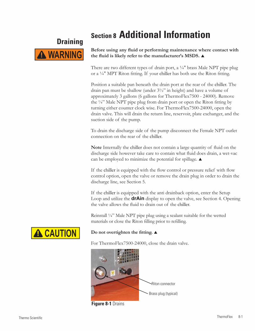
ThermoFlex 8-1 Thermo Scientific
DrainingSection 8 Additional InformationBefore using any fluid or performing maintenance where contact with the fluid is likely refer to the manufacturer’s MSDS.
There are two different types of drain port, a ¼" brass Male NPT pipe plug or a ¼" MPT Riton fitting. If your chiller has both use the Riton fitting.
Position a suitable pan beneath the drain port at the rear of the chiller. The drain pan must be shallow (under 3½” in height) and have a volume of approximately 3 gallons (6 gallons for ThermoFlex7500 - 24000). Remove the ¼” Male NPT pipe plug from drain port or open the Riton fitting by turning either counter clock wise. For ThermoFlex7500-24000, open the drain valve. This will drain the return line, reservoir, plate exchanger, and the suction side of the pump.
To drain the discharge side of the pump disconnect the Female NPT outlet connection on the rear of the chiller.
Note Internally the chiller does not contain a large quantity of fluid on the discharge side however take care to contain what fluid does drain, a wet-vac can be employed to minimize the potential for spillage.
If the chiller is equipped with the flow control or pressure relief with flow control option, open the valve or remove the drain plug in order to drain the discharge line, see Section 5.
If the chiller is equipped with the anti drainback option, enter the Setup Loop and utilize the drAin display to open the valve, see Section 4. Opening the valve allows the fluid to drain out of the chiller.
Reinstall ¼” Male NPT pipe plug using a sealant suitable for the wetted materials or close the Riton filling prior to refilling.
Do not overtighten the fitting.
For ThermoFlex7500-24000, close the drain valve.
WARNING
Figure 8-1 Drains
Brass plug (typical)
Riton connector
CAUTION

Section 8
8-2 ThermoFlex Thermo Scientific
Water-Cooled Draining ThermoFlex1400 - 2500 water-cooled chillers is accomplished by removing the right side panel. Use a Phillips head screwdriver to remove the five screws indicated in the illustration below. Slide the panel back approximately one inch, then lift slightly from the rear to disengage the panel's two tabs from their slots.
Petcock Valve
The drain for ThermoFlex3500 and 5000 is located behind the condenser filter.
The drain for ThermoFlex7500 and 10000 is located behind the access panel on the lower left front of the chiller. The panel has two ¼ turn fasteners (cross head).
The drain for Thermoflex15000 - 24000 is a ¼" plug located on the rear of the chiller.
Figure 8-2 Water-Cooled
Install a 7/16" ID tube on the drain petcock valve located on the lower end of the exchanger. Open the valve to allow fluid to drain into an external device. When draining is complete close the valve and replace the panel.
A wet-vac is needed on the facility water inlet connection to thoroughly drain any remaining fluid from the lines.

Section 8
ThermoFlex 8-3 Thermo Scientific
Wetted Materials P 1 and P 2 Pumps300 Series Stainless SteelBronzeCarbon GraphiteCeramicFluorocarbon (Viton®)Polysulfone
TankPolyethyleneBrassEPDM Pyrex®
Plumbing300 Series Stainless SteelBronzeFluorocarbon (Viton®)NickelPolypropyleneEPDMBrassCopperTeflon®
PPS (flow transducer)Nitrile (Buna-n®)Riton® (optional drain fitting)Viton® (optional drain fitting o-rings)
Filter bagPolypropyleneMono-filament nylon
Cap and FunnelAcetal Copolymer
P 3, P 4 and P 5 Pumps316 Series Stainless SteelCarbonSilicon CarbideFluorocarbon (Viton®)
T 0 and T 1 PumpsStainless Steel AISI 304Bronze ASTM B62 Bronze ASTM B16Buna NBuna/CeramicBuna/Carbon
T 5 PumpsStainless Steel AISI 304Bronze w/monel CarbonBuna NCeramicBuna/Carbon

Section 8
8-4 ThermoFlex Thermo Scientific
Internal Fluid Temperature Sensor
(rdt1) Calibration
The ThermoFlex has been designed to minimize the need for calibration. However, if calibration is desired or recommended by our Sales, Service and Customer Support, please use the following procedure.
This procedure requires a running chiller and a calibrated reference thermometer.
Note Uninsulated applications may cause the internal temperature and an external reference temperature to differ and to fluctuate. If inaccurate calibration is suspected, place the reference thermometer as close to the ThermoFlex process outlet as possible.
Note If it is more convenient, perform the low-end calibration before doing the high-end.
Do not pick calibration points that are outside the safe operating limits of the fluid in your application. For example with water, 40°C and 5°C are typical high and low calibration points.
Run the temperature to a suitable high-end calibration point. Place a calibrated reference thermometer in the reservoir. Ensure the fluid temperature is stabilized.
To enter the Calibration Loop ensure the controller display is displaying the process fluid temperature, see the diagram on next page. Press and hold the and then press the key. The display will indicate CAL.
Press the key and the controller will display rtd1. Press again and the controller will display r1 H (high-end calibration). Press again and the controller will flash between r1 H and the temperature. Use to adjust the temperature to match the reference thermometer.
Press the key again to accept the value.
Press the key until StorE is displayed, press to save the new value, press to not save it.
Note After pressing the button at the StorE prompt wait several seconds before proceeding to ensure that a bad calibration message (Er 16) does not appear. Premature use of the keypad after pressing may cancel the bad calibration error message.
Run the temperature to a suitable low-end calibration point. At the r1 L (low-end calibration) display repeat the procedure.

Section 8
ThermoFlex 8-5 Thermo Scientific
xx.x
xx.x
xx
xx
r1 H
r1 L
r1 H
r1 L
xx.x C
mode
rtd1
PrES1
Flo
r rtd
A in
Aout1
CALenter
enter enter
enter
enter
enter
StorE
mode
indicates the controller display is alternating between the two displays.
indicates press and hold.
Figure 8-3 Internal Temperature Sensor Calibration
Shaded displays only appear on chillers equipped with that option.
If you have any questions please contact Thermo Fisher Scientific's Sales, Service and Customer Support.

Section 8
8-6 ThermoFlex Thermo Scientific
Process Fluid Pressure (P1)
Transducer Calibration
The ThermoFlex has been designed to minimize the need for calibration. However, if calibration is desired or recommended by our Sales, Service and Customer Support, please use the following procedure.
This procedure requires a running chiller, a calibrated reference pressure gauge and an external flow control valve.
Connect a calibrated reference pressure gauge to the outlet line. Using an external flow control valve, increase the pressure to a suitable high-end calibration point by closing the valve. Ensure the pressure is stabilized.
To enter the Calibration Loop ensure the controller display is displaying the process fluid temperature, see the diagram on the next page. Press and hold the and then press the key. The display will indicate CAL.
Press the key and the controller will display rtd1. Press until the controller displays PrES1. Press and the controller will flash between P1H and the pressure.
Use to adjust the rate to match the reference pressure gauge.
Press the key to accept the value.
Decrease the pressure to a suitable low-end calibration point (avoid a zero pressure). Ensure the pressure is stable.
The controller will flash between P1L and the pressure. Use to adjust the rate to match the reference pressure gauge.
Press the key and StorE is displayed, press to save both values, press to not save them.
Note After pressing the button at the StorE prompt wait several seconds before proceeding to ensure that a bad calibration message (Er 16) does not appear. Premature use of the keypad after pressing may cancel the bad calibration error message.

Section 8
ThermoFlex 8-7 Thermo Scientific
xx.x
xx.x
xx
xx
P1 H
P1 L
P1 H
P1 L
xx.x C
mode
rtd1
PrES1
Flo
r rtd
A in
Aout1
CALenter
enter enter
enter
enter
enter
StorE
mode
If you have any questions please contact Thermo Fisher Scientific's Sales, Service and Customer Support.
Figure 8-4 Pressure (P1) Calibration
indicates the controller display is alternating between the two displays.
indicates press and hold.
Shaded displays only appear on chillers equipped with that option.

Section 8
8-8 ThermoFlex Thermo Scientific
Optional Process Fluid Flow Transducer (FLo)
Calibration
The ThermoFlex has been designed to minimize the need for calibration. However, if calibration is desired or recommended by our Sales, Service and Customer Support, please use the following procedure.
This procedure requires a running chiller, a calibrated reference flowmeter and an external flow control valve.
Connect a calibrated reference flowmeter to the outlet line. Using an external flow control valve, increase the flow to a suitable high-end calibration point. Ensure the flow is stabilized.
To enter the Calibration Loop ensure the controller display is displaying the process fluid temperature, see the diagram on the next page. Press and hold the and then press the key. The display will indicate CAL.
Press the key and the controller will display rtd1. Press until the controller displays FLo. Press and the controller will flash between HiFLo and the flow rate.
Use to adjust the rate to match the reference flowmeter.
Press the key to accept the value.
Decrease the flow to a suitable low-end calibration point (avoid a zero flow rate). Ensure the flow is stable.
The controller will flash between LoFLo and the flow rate. Use to adjust the rate to match the reference flowmeter.
Press the key and StorE is displayed, press to save both values, press to not save them.
Note After pressing the button at the StorE prompt wait several seconds before proceeding to ensure that a bad calibration message (Er 16) does not appear. Premature use of the keypad after pressing may cancel the bad calibration error message.

Section 8
ThermoFlex 8-9 Thermo Scientific
If you have any questions please contact Thermo Fisher Scientific's Sales, Service and Customer Support.
Figure 8-5 Flow Transducer (FLo) Calibration
indicates the controller display is alternating between the two displays.
indicates press and hold.
xx.x C
mode
rtd1
PrES1
Flo
r rtd
A in
Aout1
CALenter
StorE
xx.x
xx.x
xx
xx
HiFLo
LoFLo
enter
enter
enter
mode Shaded displays only appear on chillers equipped with that option.

Section 8
8-10 ThermoFlex Thermo Scientific
enter
enter
SEtuP
mode modemode
diA9
mode
mode
SP
mode Press within 10 seconds
FLtrS
StEPS 0enter
voLtS
xx.x
Beep
SEr1
Shipment Storage
Follow the manufacturer's MSDS instructions if decontamination is required.
Transporting and/or storing the chiller in near or below freezing temperatures requires draining, see Draining in this Section. Store the chiller in the temperature range of -25°C to 60°C (with packaging), and <80% relative humidity.
If the chiller is stored for more than 90 days it must be flushed with clean fluid before operating.
CAUTION
CAUTION
CAUTION
Clearing SEr1 Message
Press the down arrow (approximately 11 times) until StEPS is displayed.
Press and hold enter and then press the up arrow, the display will show 0.
Press the down arrow to return to the temperature display.
With SEr1 flashing press and hold enter and then press mode three times, the controller should beep.
Press the mode key until diA9 is displayed. Press enter.

ThermoFlex A-1 Thermo Scientific
Appendix A Country Specific 230 VAC, 50 Hz, 1Ø RequirementsRefer to the nameplate label located on the rear of the chiller for specific electrical requirements.
1. Chillers shipped to the following locations require a 16 Amp service:
Afghanistan, Albania, Algeria, Andorra, Angola, Argentina, Armenia,Austria, Azerbaijan, Belarus, Belgium, Benin, Bolivia, Bosnia andHerzegovina, Brazil, Bulgaria, Burkina Faso, Burundi, Cambodia,Cameroon, Cape Verde, Central African Republic, Chad, Chile, Comoros,Congo, Croatia, Czech Republic, Denmark, Djibouti, DR Congo,Ecuador, Egypt, Eritrea, Estonia, Ethiopia, Finland, France, FrenchGuiana, Gabon, Georgia, Germany, Greece, Guinea, Hungary, Iceland,Indonesia, Iran, Iraq, Israel, Italy, Ivory Coast, Jordan, Kazakhstan,Kyrgyzstan, Latvia, Lebanon, Liberia, Libya, Liechtenstein, Lithuania,Luxembourg, Madagascar, Mali, Mauritania, Moldova, Monaco,Mongolia, Morocco, Mozambique, Namibia, Nepal, Netherlands, Niger,North Korea, Norway, Paraguay, Peru, Poland, Portugal, Romania,Russia, Rwanda, Saint Vincent and the Grenadines, San Marino, SaoTome and Principe, Saudi Arabia, Senegal, Serbia, Slovakia, Slovenia,Somalia, South Africa, South Korea, Spain, Sweden, Switzerland, Syria,Tajikistan, Thailand, Togo, Tunisia, Turkey, Turkmenistan, Ukraine,Uruguay, Uzbekistan, Vanuatu, Vatican City, Vietnam.
2. Chillers shipped to the following locations require a 15 Amp service:
Australia, China, Fiji Islands, Nauru, New Zealand, Papua New Guinea,Solomon Island, Tonga, Tuvalu.
3. Chillers shipped to the following locations require a 13 Amp service:
Abu Dhabi, Bahrain, Bangladesh, Botswana, Brunei, Cyprus, Dominica,Gambia, Ghana, Gibraltar, Grenada, Hong Kong, India, Ireland, Kenya,Kiribati, Kuwait, Lesotho, Malawi, Malaysia, Maldives, Malta, Mauritius,Myanmar, Nigeria, Oman, Pakistan, Qatar, Saint Lucia, Seychelles, SierraLeone, Singapore, Sri Lanka, Sudan, Swaziland, Tanzania, Uganda,United Arab Emirates, United Kingdom Yemen, Zambia, Zimbabwe.

ThermoFlex B-1 Thermo Scientific
Appendix B Voltage Configuration InstructionsThermoFlex 900 and 1400 chillers equipped with the 115V 60Hz, 100v 50/60Hz Variable Voltage option and ThermoFlex 900 to 5000 chillers equipped with 200-230V 50/60Hz Global Voltage option have a voltage configuration panel located on the rear of the chiller behind an access panel, see Figure B-1.
• Use a 1/4” socket to remove the four screws securing the access panel to the chiller.
• The configuration panel has two 3-position toggle switches, one for voltage and one for frequency. All chillers are shipped with the toggle switch in the center SHIP position. Place each switch to the settings that match the voltage/frequency supplied to the chiller.
Note For ThermoFlex900-2500 global voltage chillers, the compressor and fan will not operate when the switch is in the SHIP position.
• Reinstall the access panel.
Access Panel for 900 - 2500 chillers.
Access Panel for 3500 - 5000 chillers.
Variable Voltage chillers
Global Voltage chillers
Figure B-1 Variable/Global Voltage Chillers

ThermoFlex C-1 Thermo Scientific
Appendix C Analog I/0 and Remote Sensor
Analog I/O Connector PinoutInstall your analog input/output device to the 15-pin female connector on the rear of the chiller. Analog I/O is activated using the Setup Loop, see page C-3.
PIN NAME NOTES DEFINITION
1 DIGITAL GROUND Common round connection for pins 12, 13 and 14
2 Not Used
3 LOW LEVEL Note 1 Dry Relay Contact: Reference to pin 11. (Only if option chosen) Closes if either level switch is in the “low” position for more than 1 second.
4 CONFIGURABLE RELAY 2 Note 1 Dry Relay Contact: Reference to pin 11. Closes when any configured fault or warning occurs, see Table 2.
5 PUMP ON Note 1 Dry Relay Contact: Reference to pin 11. Closes when pump is turned on. Opens when pump is turned off.
6 ANALOG GROUND Common for analog signals (pins 2, 7 and 15)
7 RESERVOIR TEMP OUT Note 2 Analog Voltage Output 0-10VDC, 10mV/°C, or 4-20mA: Reference to pin 6. OR EXTERNAL SENSOR This voltage output is proportional to the reservoir fluid temperature: TEMPERATURE IF Default scale= 0–10V (where: 0V = Low Temp Span, 10V = Hi Temp Span) EXTERNAL SENSOR Optional Range = 10mV/ OC. (Ex: 200mV = 20°C) (Max Load @ 10V = 5mA) ENABLED or 4-20mA, 4mA = low temp span, 20 mA = high temp span (maximum output current = 5mA @10VDC.
8 LOW FLOW Note 1 Dry Relay Contact: Reference to pin 11. (Only if option chosen) Closes when a low flow occurs while the pump is on. Note: To allow the pump to get up to speed at startup, the pump runs for 3 - 5 seconds before the low flow sensor is read.
9 CONFIGURABLE RELAY 1 Note 1 Dry Relay Contact: Reference to pin 11. (Normally Open) Closes when any of the configured faults occur, see Table 1.
10 CONFIGURABLE RELAY 1 Note 1 Dry Relay Contact: Reference to pin 11. (Normally Closed) Complement of pin 9 (open when pin 9 is closed).
11 RELAY COMMON Common for all relay contacts (pins 3, 4, 5, 8, 9, 10).
12 REMOTE START Note 3 Connect to pin 1 to allow chiller to be remotely turned on/off through pin 14 ENABLE REMOTE START.
Note 1: All relay contacts (except for Pin 10) are normally OPEN when power is off. Pin 10 contacts are normally CLOSED when power is off. Relay contacts are rated: 24V AC/DC, 2A, <= 0.08 Ohm maximum each or 5A total for all relays combined, 1mA minimum, switching capacity: 48VA/48W (Resistive load only).
Note 2: Default = 0-10VDC
Note 3: Connect to digital ground (pin 1) using a low resistance connection (gold contact relay).
8 7 6 5 4 3 2 1
15 14 13 12 11 10 9

Thermo ScientificC-2 ThermoFlex
Appendix C
Thermo Scientific Thermo Scientific
PIN NAME NOTES DEFINITION
13 REMOTE SETPOINT Note 3 Connect to pin 1 to allow the setpoint to be changed remotely through pin 15 ENABLE REMOTE SETPOINT.
14 REMOTE START Note 3 Connect to pin 1 to turn chiller on. Disconnect to turn chiller off. Note: Pins 1 and 12 must be connected to allow operation from this pin.
15 REMOTE SETPOINT Note 2, 4 Analog Voltage Input 0-10VDC, 10mV/°C, or 4-20mA: Reference to pin 6. Apply a DC voltage to this pin to adjust the chiller's setpoint: Default Range = 0 – 10V (where: 0V = Low Temp Span, 10V = Hi Temp Span) (Input Impedance > 600K) Optional Range = 10mV/ OC. (Ex: 200mV = 20°C) (Max Input Voltage = 10VDC, or 4-20mA, 4mA = low temp span, 20 mA = high temp span.
Note 1: All relay contacts (except for Pin 10) are normally OPEN when power is off. Pin 10 contacts are normally CLOSED when power is off. Relay contacts are rated: 24V AC/DC, 2A, <= 0.08 Ohm maximum each or 5A total for all relays combined, 1mA minimum, switching capacity: 48VA/48W (Resistive load only).
Note 2: Default = 0-10VDC
Note 3: Connect to digital ground (pin 1) using a low resistance connection (gold contact relay).
Note 4: Remote setpoint must be enabled, pin 13
Figure C-1 Analog I/0 Connector
When making your connection to the ThermoFlex Analog I/0 connector, in order to comply with the EMC directive:
• Use a shielded I/0 cable
• Connect the remote end of the cable shield to earth ground.
• Connect cable shield to ThermoFlex end connector.
A I/0 15-pin D-sub 15 conductor cable with shield
Connect shield to earth groundConnect shield to ThermoFlex connector
1 2 3 4 5
6 7 8 91 2 3 4 5
6 7 8 9
1 2 3 4 5
6 7 8 98 7 6 5 4 3 2 1
15 14 13 12 11 10 9
RS232 RS485
A I/O REMOTE SENSOR
8 7 6 5 4 3 2 1
15 14 13 12 11 10 9
Never apply line voltage to any of the connections. WARNING

Thermo Scientific
Appendix C
ThermoFlex C-3 Thermo Scientific
• rELAY is used to configure relay 1 (CodE 1) and relay 2 (CodE 2), see Tables 1 and 2 on the next page.
For example: To have just the drip pan, 4, and low temp, 8, error faults enabled for relay 1 you would enter their sum, 12, at the CodE 1 display. To have the tank overflow, 2, the low temp, 16, and high pressure, 1024, error faults enabled for relay 2 you would enter their sum, 1040, at the CodE 2 display.
This display depends on your chillerconfiguration, see Section 4.
Figure C-2 Analog I/0 Loop
xx.x Cxx.x C xx.x C xx.x Cxx.x C xx.x C
• r rtd is used to enable/disable the remote temperature sensor. See Table 3 for pin out information.
Note There is no other indication on the chiller that the remote sensor is enabled.
• r.Start is used to enable/disable the remote start/stop.
Note Enabling analog I/O remote start/stop disables the chiller’s local controller start/stop capability. Enabling analog I/O remote also overrides serial communications start/stop commands.
• r SEt is used to enable/disable the remote setpoint.
Note When remote setpoint is enabled a flashing dot will appear on the controller's display as shown below.
• AnAin is used to configure the analog voltage input type.Type 1: 0 - 10 VDC (Default)Type 2: 10 mV/°CType 3: 4 - 20 mA
• dAC is used to enable/disable the digital to analog converter. Once enabled, the desired output type can be selected.
Note The Type display only appears if dAC is set to on.
Type 1: 0 - 10 VDC (Default)Type 2: 10 mV/°CType 3: 4 - 20 mA
rELAY
CodE 1
CodE 2
enter
enter
xx
xx
xxxxx
xxxxx
enter
enter
r rtd
r.Start
r SEt
AnAin
dAC
dAC
----
xx
xx
xx
xx
xx
xx
xx
xx
xx
xx
OFF
OFF
OFF
OFF
on
on
on
on
tYPE1
tYPE1
enter
enter
enter
enter
enter
enter
enter
enter
enter
enter
enter
OPt

Thermo ScientificC-4 ThermoFlex
Appendix C
Thermo Scientific Thermo Scientific
Table 1 Configurable Relay #1 (CodE1)
Error Error Code Factory Default Low Level (option) LLF Enable 1 (Default)Tank Overflow o FLo Disable 2Drip Pan Full (option) driP Disable 4Low Temp Lo t* Disable 8High Temp Hi t* Disable 16Low Flow (option) LoFLo* Enable 32 (Default)High Flow (option) HiFLo* Disable 64Low Resistivity (option) Er 28* Disable 128High Resistivity (option) Er 30* Disable 256
High Pressure Hi P1* Disable 512Low Pressure Lo P1* Disable 1024Chiller Fault Any Fault Enable 2048 (Default)Pump/Chiller Shut Off Status bit(s) Disable 4096Refrigeration Shut Off Status Bit Disable 8192Limit Fault (option) PHEr, oL, LPC, HPC, Er 47, Er 48 Enable 16384 (Default)Sensor Fault Er 23, Er 24, Er 25, Er 26 Disable 32768 external sensor opened or shorted Default Relay Code 1 Display = 18465 (1 + 32 + 2048 + 16384 = 18465)
*Regardless of alarm setting - fault or indicator
Table 2 Configurable Relay #2 (CodE2)
Error Error Code Factory Default Low Level (option) Add Disable 1Tank Overflow o FLo Disable 2Drip Pan Full (option) driP Disable 4Auto Refill Error (option) rEFiL Disable 8Low Temp Lo t* Enable 16 (Default)High Temp Hi t* Enable 32 (Default)Low Flow (option) Lo FL* Disable 64High Flow (option) Hi FL* Disable 128Low Resistivity (option) Er 28* Disable 256High Resistivity (option) Er 30* Enable 512 (Default)High Pressure Hi P1* Disable 1024Low Pressure Lo P1* Disable 2048Indicator (warning) Any Indicator Disable 4096PM Timer (option) di, SEr 1 to 6 Disable 8192Communication Error Er 15, Er 41, Er 42 Disable 16384Sensor Fault Er 23, Er 24, Er 25, Er 26 Enable 32768 (Default) external sensor opened or shorted Default Relay Code 2 Display = 33328 (16 + 32 + 512 + 32768 = 33328)
*Regardless of alarm setting - fault or indicator

Thermo Scientific
Appendix C
ThermoFlex C-5 Thermo Scientific
Analog Input Calibration
– The HMI will display 0.50/0.050/4.00. Use the arrow keys to adjust the display to match the applied input voltage/current. Allow the analog input to stabilize, approximately 10 seconds.
– Enter the measured reference voltage/current using the HMI by pressing the key. The firmware will use this value and the theoretical analog input value
and those from the high end to calculate a linear gain and offset.
– If the gain and offset are acceptable, the calibration is accepted and the calibration is now valid at the low end. Otherwise, the calibration is rejected and a bad calibration error message (Er 16) is displayed.
Figure C-3 Analog Input Calibration Loop
xx.x
xx.x
9.50
0.50
Ai HiAi Hi
Ai Lo Ai Lo
xx.x C
mode
rtd1
Flo
CAL
enter
enter enter
enter
enter
enter
mode
r rtd
A in
Aout1
StorE
PrES1
The analog input uses a 2-point calibration. Depending on how the analog input is configured Type1, Type2 or Type 3, the HMI will display either volts, millivolts or milliamps. The calibration procedure is:
– Start with default high and low endpoints each consisting of a voltage/current value and a theoretical analog input value. This will permit calibration of either point first. Both ends must be calibrated for the entire calibration to be valid.
– Connect a 9.50v/0.400mv/20.00ma reference voltage/current source to the analog input, pins 6 and 15.
– The HMI will display 9.50/0.400/20.00. Use the arrow keys to adjust the display to match the applied input voltage/current.
– Allow the analog input to stabilize, approximately 10 seconds.
– Enter the measured reference voltage/current using the HMI by pressing the key. The firmware will use this value and the theoretical analog value and
those from the low end to calculate a linear gain and offset.
– The display will automatically go to the low calibration message. Press to calibrate the analog input at the low end.
– Connect a 0.50v/0.050mv/4.00ma reference voltage/current source to the analog input.
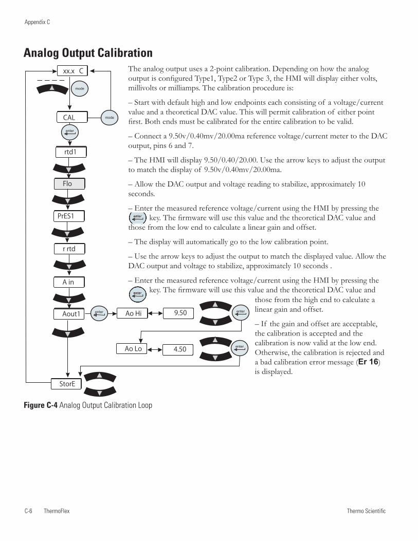
Thermo ScientificC-6 ThermoFlex
Appendix C
Thermo Scientific Thermo Scientific
xx.x
xx.x
9.50
4.50
Ao Hi
Ao Lo
xx.x C
mode
rtd1
Flo
CAL
enter
enter enter
enter
mode
r rtd
A in
Aout1
StorE
PrES1
The analog output uses a 2-point calibration. Depending on how the analog output is configured Type1, Type2 or Type 3, the HMI will display either volts, millivolts or milliamps. The calibration procedure is:
– Start with default high and low endpoints each consisting of a voltage/current value and a theoretical DAC value. This will permit calibration of either point first. Both ends must be calibrated for the entire calibration to be valid.
– Connect a 9.50v/0.40mv/20.00ma reference voltage/current meter to the DAC output, pins 6 and 7.
– The HMI will display 9.50/0.40/20.00. Use the arrow keys to adjust the output to match the display of 9.50v/0.40mv/20.00ma.
– Allow the DAC output and voltage reading to stabilize, approximately 10 seconds.
– Enter the measured reference voltage/current using the HMI by pressing the key. The firmware will use this value and the theoretical DAC value and
those from the low end to calculate a linear gain and offset.
– The display will automatically go to the low calibration point.
– Use the arrow keys to adjust the output to match the displayed value. Allow the DAC output and voltage to stabilize, approximately 10 seconds .
– Enter the measured reference voltage/current using the HMI by pressing the key. The firmware will use this value and the theoretical DAC value and
Analog Output Calibration
those from the high end to calculate a linear gain and offset.
– If the gain and offset are acceptable, the calibration is accepted and the calibration is now valid at the low end. Otherwise, the calibration is rejected and a bad calibration error message (Er 16) is displayed.
Figure C-4 Analog Output Calibration Loop

Thermo Scientific
Appendix C
ThermoFlex C-7 Thermo Scientific
Table 3
Pin
1 White 2 NA 3 NA 4 White 5 NA 6 NA 7 Red 8 NA 9 Red (4th wire not connected to the control board)
Figure C-5 Remote Sensor Connector
Remote Sensor Connector Pinout
1 2 3 4 5
6 7 8 9
1 2 3 4 5
6 7 8 91 2 3 4 5
6 7 8 9
1 2 3 4 5
6 7 8 98 7 6 5 4 3 2 1
15 14 13 12 11 10 9
RS232 RS485
A I/O REMOTE SENSOR
Never apply line voltage to any of the connections. WARNINGWhen operating a ThermoFlex7500-10000 with the remote sensor enabled ensure the chiller's response to lowering the setpoint does not result in operation below 10°C process temperature. Operation below 10°C requires the use of 50/50 EG/water or 50/50 PG/water.
CAUTION

Thermo ScientificC-8 ThermoFlex
Appendix C
Thermo Scientific
Press the key again to accept the value.
Place the remote sensor and calibrated reference thermometer in a low temperature reservoir. At the rtd L (low-end calibration) display repeat the procedure.
After the low-end calibration is accepted StorE is displayed. Press the up arrow to accept the calibration, press the down arrow key to not accept it.
Note After pressing the up arrow button at the StorE prompt wait several seconds before proceeding to ensure that a bad calibration message (Er 16) does not appear. Premature use of the keypad after pressing the up arrow may cancel the bad calibration error message.
Remote Sensor Calibration
Figure C-6 Remote Sensor Calibration Loop
xx.x
xx.x
xx.x
xx.x
Rdt Hrtd H
rtd L rdt L
xx.x C
mode
rtd1
Flo
CAL
enter
enter enter
enter
enter
enter
mode
r rtd
A in
Aout1
StorE
PrES1
This procedure requires a running chiller and a calibrated reference thermometer.
Note If it is more convenient, perform the low-end calibration before doing the high-end.
Do not pick calibration points that are outside the safe operating limits of the fluid in your application. For example with water, 40°C and 5°C are typical high and low calibration points.
Place the remote sensor and a calibrated reference thermometer in the high temperature remote reservoir. Ensure the fluid temperature is stabilized.
Press the key and the controller will display rtd H. Press again and the controller will flash between rtd H and the temperature. Use the arrow keys to adjust the temperature to match the reference thermometer.

ThermoFlex D-1 Thermo Scientific
Appendix D NC Serial Communications Protocol
Note Appendix D assumes you have a basic understanding of communications protocols.
Never apply line voltage to any of the connections.
Connect your PC to the applicable connector on the rear of the chiller. Use the Setup Loop, see Section 4, to enable serial communications.
Note Keypad operation is still available with serial communications enabled.
• SEr is used to enable/disable and to configure serial communications.Range: oFF, rS232, rS485 Default: oFF
This display depends on your chillerconfiguration, see Section 4.
Figure D-1 Connectors
Figure D-2 Serial Communications Loop
BAud
StoP
dAtA
PAr
uid
----
SEr SEr
enter
enter
enter
enter
enter
enter
xx
xx
xx
xx
xx
xx
xxxx
8
xxxx
x
xx
xx
enter
enter
enter
enter
enter
1 2 3 4 5
6 7 8 91 2 3 4 5
6 7 8 9
1 2 3 4 5
6 7 8 98 7 6 5 4 3 2 1
15 14 13 12 11 10 9
RS232 RS485
A I/O REMOTE SENSOR
• BAud is used to select the baud rate (speed) for serial communications.Range: 9600, 4800, 2400, 1200, 600, or 300 bits per second Default: 9600
• dAtA is used to display the number of data bits.Range: Fixed at 8
• StoP is used to indicate the number of stop bits.Range: 2 or 1 Default: 1
• PAr is used as a means to check for communication errors.Range: even, odd, or none Default: none
• u id (chiller id) is used in RS485 only. Identifies devices connected to the RS 485 port.Range: 1 to 99 Default: 1
Note: To prevent data errors limit the number of chillers to 32.
WARNING
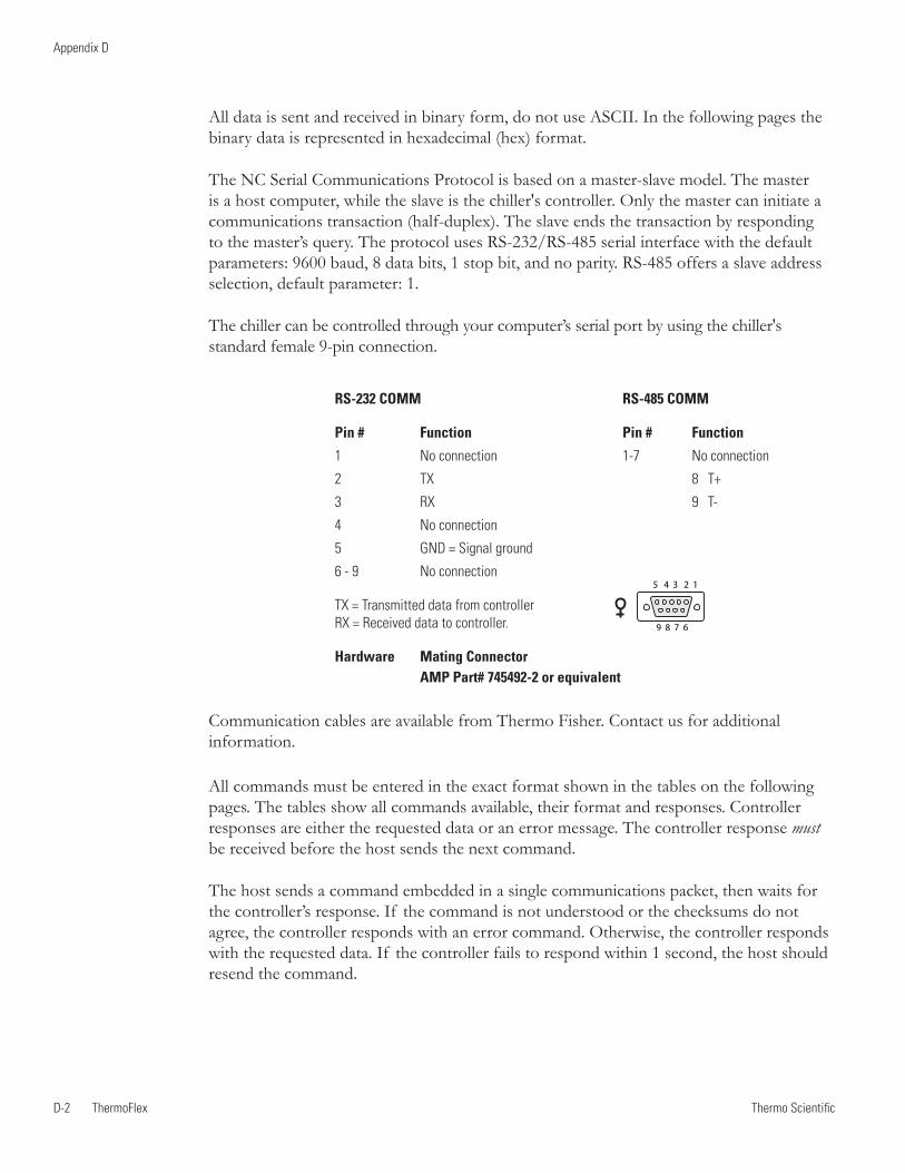
Thermo ScientificD-2 ThermoFlex
Appendix D
Thermo Scientific Thermo Scientific
RS-232 COMM RS-485 COMM
Pin # Function Pin # Function
1 No connection 1-7 No connection
2 TX 8 T+
3 RX 9 T-
4 No connection
5 GND = Signal ground
6 - 9 No connection
TX = Transmitted data from controller RX = Received data to controller.
Hardware Mating Connector AMP Part# 745492-2 or equivalent
All data is sent and received in binary form, do not use ASCII. In the following pages the binary data is represented in hexadecimal (hex) format.
The NC Serial Communications Protocol is based on a master-slave model. The master is a host computer, while the slave is the chiller's controller. Only the master can initiate a communications transaction (half-duplex). The slave ends the transaction by responding to the master’s query. The protocol uses RS-232/RS-485 serial interface with the default parameters: 9600 baud, 8 data bits, 1 stop bit, and no parity. RS-485 offers a slave address selection, default parameter: 1.
The chiller can be controlled through your computer’s serial port by using the chiller's standard female 9-pin connection.
Communication cables are available from Thermo Fisher. Contact us for additional information.
5 4 3 2 1
9 8 7 6
All commands must be entered in the exact format shown in the tables on the following pages. The tables show all commands available, their format and responses. Controller responses are either the requested data or an error message. The controller response must be received before the host sends the next command.
The host sends a command embedded in a single communications packet, then waits for the controller’s response. If the command is not understood or the checksums do not agree, the controller responds with an error command. Otherwise, the controller responds with the requested data. If the controller fails to respond within 1 second, the host should resend the command.

Thermo Scientific
Appendix D
ThermoFlex D-3 Thermo Scientific
Note All byte values are shown in hex, hex represents the binary values that must be sent to the chiller. Do not use ASCII.
The framing of the communications packet in both directions is:
Checksum region
Lead char Addr-MSB Addr-LSB Command n d-bytes d-byte 1 ... d-byte n Checksum
Lead char 0xCA (RS-232) 0xCC (RS-485) Device address is 1 (RS-232)Addr-msb Most significant byte of slave address (RS-232: 0)Addr-lsb Least significant byte of slave address (RS-232: 1)Command Command byte (see Table of Commands)n d-bytes Number of data bytes to follow d-byte 1 1st data byte (the qualifier byte is considered a data byte)... ...d-byte n nth data byte.Checksum Bitwise inversion of the 1 byte sum of bytes beginning with the most significant address byte and ending with the byte preceding the checksum. (To perform a bitwise inversion, "exclusive OR" the one byte sum with FF hex.)
When a command has no value associated with it (e.g., REQ ACK), “n d-bytes” will be set to 0. Values such as temperature and flow are sent as either 2 or 4 byte signed integers, depending on how they are stored in the controller RAM.
When the controller sends a value, a qualifier byte is sent first, followed by a 2 or 4 byte integer (the least significant byte is sent last). The qualifier indicates the precision and units of the value. The host does not send the qualifier byte; it must send the value using the correct precision, units and number of bytes. The host first inquires about a value it wants to change, then uses the number of data bytes and the qualifier byte it receives to generate the proper integer to send.
OxCA/OxCC

Thermo ScientificD-4 ThermoFlex
Appendix D
Thermo Scientific Thermo Scientific
Analog Values
Qualifier Byteb.7 b.6 b.5 b.4 b.3 b.2 b.1 b.0
A qualifier byte of 0x12 indicated that the value contains one decimal point and the units are °F , e.g., 98.6°F.
Examples to set setpoint to 25°C:
A. The precision and units are 1°C; a 2 byte integer is used. If you already know this, skip to step 3.
1. Master sends: CA 00 01 70 00 8E (Request Setpoint 1)2. Slave responds: CA 00 01 70 03 01 00 14 76 Precision =1, units =°C, value=20 (20 x 1°C=20°C) Response indicates: uses a 2 byte integer (nn=03) precision and units are 1°C (d1=01)3. Master sends: CA 00 01 F0 02 00 19 F3 (Set Setpoint 1 to 25°C)4. Slave responds: CA 00 01 F0 03 01 00 19 F1 Precision =1, units =°C, value=25 (25 x 1°C=25°C)
B. The precision and units are 0.1°C; a 2 byte integer is used. If you already know this, skip to step 3.
1. Master sends: CA 00 01 70 00 8E (REQ SETPOINT1)2. Slave responds: CA 00 01 70 03 11 00 C8 B2 Precision =0.1, units =°C, value=200 (200 x 0.1°C=20.0°C) Response indicates: uses a 2 byte integer (nn=03) precision and units are 0.1°C (d1=11)3. Master sends: CA 00 01 F0 02 00 FA 12 (Set Setpoint 1 to 25.0°C)4. Slave responds: CA 00 01 F0 03 11 00 FA 00 Precision =0.1, units =°C, value=250 (250 x 0.1°=25.0.0°C)
See Additional Command Examples in this Appendix.
Unit of MeasureIndex Unit0 NONE1 Temperature in °C2 Temperature in °F3 Flow liters per minute4 Flow in gallons per minute5 Time in seconds6 Pressure in PSI7 Pressure in bars8 Resistivity in MΩ-cm 9 % 10 Volts 11 Pressure in kPa
Precision of measurement
Unit of measure index

Thermo Scientific
Appendix D
ThermoFlex D-5 Thermo Scientific
Table of Commands
Command M: Master Sends Notes S: Slave RespondsRequest Status
REQ ACK M: lc a1 a2 00 00 cs protocol version v1=0; v2=1 S: lc a1 a2 00 02 v1 v2 cs
REQ CONTROLLER SW VER M: lc a1 a2 02 00 cs Controller SW version in ASCII or FIRMWARE CHECKSUM S: lc a1 a2 02 nn d1 … dn cs
Example: Request SW version, controller returns 084992.2N1. Master sends: lc a1 a2 02 00 cs 2. Slave responds: lc a1 a2 02 0A 30 38 34 39 39 32 2E 32 4E 20 E4
Example: Request controller checksum, controller returns 20FA1. Master sends: CA 00 01 02 01 01 FA 2. Slave responds: CA 00 01 02 04 32 30 46 41 0F
REQ DISPLAY MSG M: lc a1 a2 07 00 cs Display message in ASCII S: lc a1 a2 07 nn d1 … dn cs
REQ STATUS M: lc a1 a2 09 00 cs see Request Status Table in this Appendix S: lc a1 a2 09 nn d1 … dn cs
ERROR M: Response Only! S: lc a1 a2 0F 02 en ed cs ed = Error Data en = Error Number 1: Bad Command 2: Bad Data 3: Bad Checksum See Error in this Appendix

Thermo ScientificD-6 ThermoFlex
Appendix D
Thermo Scientific Thermo Scientific
REQUEST LOW ALARM VALUES
REQ LO FLOW1 M: lc a1 a2 30 00 cs Process Alarm S: lc a1 a2 30 03 d1 d2 d3 cs
REQ LO TEMP1 M: lc a1 a2 40 00 cs Process Alarm S: lc a1 a2 40 03 d1 d2 d3 cs
REQ LO ANALOG1 M: lc a1 a2 48 00 cs Pressure Process Supply Alarm S: lc a1 a2 48 03 d1 d2 d3 cs
REQUEST HIGH ALARM VALUES
REQ HI FLOW1 M: lc a1 a2 50 00 cs Process Alarm S: lc a1 a2 50 03 d1 d2 d3 cs
REQ HI TEMP1 M: lc a1 a2 60 00 cs Process Alarm S: lc a1 a2 60 03 d1 d2 d3 cs
REQ HI ANALOG1 M: lc a1 a2 68 00 cs Pressure Process Supply Alarm S: lc a1 a2 68 03 d1 d2 d3 cs
REQUEST MEASUREMENTS
REQ FLOW1 M: lc a1 a2 10 00 cs Process Fluid Flow S: lc a1 a2 10 03 d1 d2 d3 cs
REQ TEMP1 M: lc a1 a2 20 00 cs Process Fluid Supply Temperature (RTD1) S: lc a1 a2 20 03 d1 d2 d3 cs
REQ TEMP4 M: lc a1 a2 23 00 cs Remote Temperature (RTD4) S: lc a1 a2 23 03 d1 d2 d3 cs
REQ ANALOG1 M: lc a1 a2 28 00 cs Process Fluid Supply Pressure (P1) S: lc a1 a2 28 03 d1 d2 d3 cs
REQ ANALOG2 M: lc a1 a2 29 00 cs Refrigeration Suction Pressure (P2) S: lc a1 a2 29 03 d1 d2 d3 cs
REQUEST PID SETTINGS
REQ SETPT1 M: lc a1 a2 70 00 cs Process Fluid Setpoint S: lc a1 a2 70 03 d1 d2 d3 cs
REQ COOL P TERM1 M: lc a1 a2 74 00 cs S: lc a1 a2 74 03 d1 d2 d3 cs
REQ COOL I TERM1 M: lc a1 a2 75 00 cs S: lc a1 a2 75 03 d1 d2 d3 cs
REQ COOL D TERM1 M: lc a1 a2 76 00 cs S: lc a1 a2 76 03 d1 d2 d3 cs

Thermo Scientific
Appendix D
ThermoFlex D-7 Thermo Scientific
SET STATUS SETTINGS
SET KEYSTROKE M: lc a1 a2 80 01 d1 cs See Keystroke in this Appendix S: lc a1 a2 80 01 d1 cs
SET ON/OFF ARRAY M: lc a1 a2 81 nn d1 … dn cs See Set On/Off Array in this Appendix S: lc a1 a2 81 nn d1 … dn cs d1: 0 = OFF, 1 = ON, 2 = no change
SET LOW ALARM VALUES
SET LO FLOW1 M: lc a1 a2 B0 02 d1 d2 cs Process Alarm S: lc a1 a2 B0 03 d1 d2 d3 cs
SET LO TEMP1 M: lc a1 a2 C0 02 d1 d2 cs Process Alarm S: lc a1 a2 C0 03 d1 d2 d3 cs
SET LO ANALOG1 M: lc a1 a2 C8 02 d1 d2 cs Pressure Process Supply Alarm S: lc a1 a2 C8 03 d1 d2 d3 cs
SET HIGH ALARM VALUES
SET HI FLOW1 M: lc a1 a2 D0 02 d1 d2 cs Process Alarm S: lc a1 a2 D0 03 d1 d2 d3 cs
SET HI TEMP1 M: lc a1 a2 E0 02 d1 d2 cs Process Alarm S: lc a1 a2 E0 03 d1 d2 d3 cs
SET HI ANALOG1 M: lc a1 a2 E8 02 d1 d2 cs Pressure Process Supply Alarm S: lc a1 a2 E8 03 d1 d2 d3 cs
SET PID Settings
SET SETPT1 M: lc a1 a2 F0 02 d1 d2 cs Process Fluid Setpoint S: lc a1 a2 F0 03 d1 d2 d3 cs
SET COOL P TERM1 M: lc a1 a2 F4 02 d1 d2 cs Cool P Term S: lc a1 a2 F4 03 d1 d2 d3 cs
SET COOL I TERM1 M: lc a1 a2 F5 02 d1 d2 cs Cool I Term S: lc a1 a2 F5 03 d1 d2 d3 cs
SET COOL D TERM1 M: lc a1 a2 F6 02 d1 d2 cs Cool D Term S: lc a1 a2 F6 03 d1 d2 d3 cs

Thermo ScientificD-8 ThermoFlex
Appendix D
Thermo Scientific Thermo Scientific
Request Status Table
Basic
nn 4
b0 Chiller Running
b1 RTD1 open or shorted
b2 RTD2 open or shorted
d1 b3 RTD3 open or shorted
b4 High Temp fixed fault
b5 Low Temp fixed fault
b6 High Temp fault or warn
b7 Low Temp fault or warn
b0 High Pressure fault or warn
b1 Low Pressure fault or warn
b2 Drip Pan fault
d2 b3 High Level fault
b4 Phase Monitor fault
b5 Motor Overload fault
b6 LPC fault
b7 HPC fault
b0 External EMO fault
b1 Local EMO fault
b2 Low Flow fault
d3 b3 Auto Refill fault/ Low Level fault
b4 Sense 5V fault
b5 Invalid level fault
b6 Low fixed flow warn
b7 High pressure fault (set at factory)
b0 Low pressure fault (set at factory)
d4 b1 Chiller powering up b2 Chiller powering down

Thermo Scientific
Appendix D
ThermoFlex D-9 Thermo Scientific
Error
The slave detected an error in the message it received from the master, so it returns this command instead of echoing the command sent by the master. The slave returns the command it received from the master in the ed byte, and an error code in the en byte.
en Error1 Bad command – not recognized by slave2 Bad data3 Bad checksum
Some errors may not result in any response. The slave ignores incoming bytes until it sees the valid lead character and its slave address. Then it must receive the correct number of bytes (determined by the length byte) before it can respond. If an incomplete frame is received, the slave will time out and clear its input buffer without responding.
Set On/Off Array
This command is used to set the state of the chiller, on or off. Sending a 0 in the array turns off the chiller while sending a 1 turns it on. Sending a 2 does not change the state. The array is re-turned showing the state after the command has been carried out. Sending all 2’s effectively turns this command into a request status command.
nn 1d1 Chiller On/Off
Set Keystroke
This command is used to affect a keystroke remotely as if someone pressed the key on the HMI. Value 0 Null1 Enter2 Up/Yes3 Down/No4 Mode5 On/Off
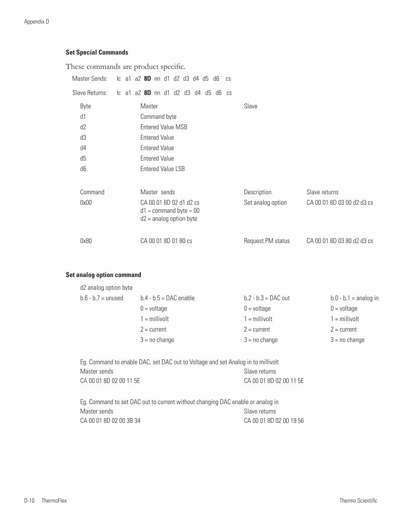
Thermo ScientificD-10 ThermoFlex
Appendix D
Thermo Scientific
Set Special Commands
These commands are product specific.Master Sends: lc a1 a2 8D nn d1 d2 d3 d4 d5 d6 cs
Slave Returns: lc a1 a2 8D nn d1 d2 d3 d4 d5 d6 cs
Byte Master Slave
d1 Command byte
d2 Entered Value MSB
d3 Entered Value
d4 Entered Value
d5 Entered Value
d6 Entered Value LSB
Command Master sends Description Slave returns
0x00 CA 00 01 8D 02 d1 d2 cs Set analog option CA 00 01 8D 03 00 d2 d3 cs d1 = command byte = 00 d2 = analog option byte
0x80 CA 00 01 8D 01 80 cs Request PM status CA 00 01 8D 03 80 d2 d3 cs
Set analog option command
d2 analog option byte
b.6 - b.7 = unused b.4 - b.5 = DAC enable b.2 - b.3 = DAC out b.0 - b.1 = analog in
0 = voltage 0 = voltage 0 = voltage
1 = millivolt 1 = millivolt 1 = millivolt
2 = current 2 = current 2 = current
3 = no change 3 = no change 3 = no change
Eg. Command to enable DAC, set DAC out to Voltage and set Analog in to millivolt Master sends Slave returns CA 00 01 8D 02 00 11 5E CA 00 01 8D 02 00 11 5E
Eg. Command to set DAC out to current without changing DAC enable or analog in Master sends Slave returns CA 00 01 8D 02 00 3B 34 CA 00 01 8D 02 00 19 56

Laboratory Equipment Div. 25 Nimble Hill Road Newington, NH 03801
D of C 094026.1 Form 094233 DWG # 094026 REV 17 Apr 07
DECLARATION OF CONFORMITY
Manufacturer: Thermo Fisher Scientific Address: 25 Nimble Hill Road Newington, NH 03801 USA Products: Refrigerated chillers and heat exchangers. Year of inception 2008
We declare that the following products conform to the Directives and Standards listed below: Unit has a 15 digit part number consisting of UU C VV PP c XXXXXXX defined as follows: UU = Unit type can be: 10 = TF 900 11 = TF 1,400 12 = TF 2,500 13 = TF 3,500 14 = TF 5,000 15 = TF 7,500 16 = TF 10,000 17 = TF 15,000 18 = TF 20,000 19 = TF 24,000 C = Cooling type and Temperature Range and can be a 1-4 inclusive, where: 1 = Air Cooled Standard Temp ( 5-40°C ) 2 = Air Cooled Hi Temp ( 5-90°C ) 3 = Water Cooled Standard Temp ( 5-40°C ) 4 = Water Cooled Hi Temp ( 5-90°C ) VV = Unit voltage rating: UU = 10, 11, 12, 13 & 14 UU = 15, 16 & 17 UU = 18 & 19 10 = 115V, 60Hz 1Ph 17 = 200/208/230V, 60Hz 3Ph 17 = 208/230V, 60Hz 3Ph 100V, 50Hz 1Ph 200V, 50Hz 3Ph 11 = 100/115V, 60Hz 1Ph 18 = 400V, 50Hz 3Ph 18 = 400V, 50Hz 3Ph 100/115V, 50Hz 1Ph 20 = 200/208/230V, 60Hz 3Ph 12 = 208/230V, 60Hz 1Ph 200-230V, 50Hz 3Ph 200V, 50Hz 1Ph 21 = 460V, 60Hz 3Ph 21 = 460V, 60Hz 3Ph 16 = 230V, 50Hz 1Ph 400V, 50Hz 3Ph 400V, 50Hz 3Ph 20 = 200/208/230V, 60Hz 1Ph 200/230V, 50Hz 1Ph PP = Pump type, can be 10 through 25 inclusive. c = Unit controller type, can be any digit from 1-6, inclusive. X = Any digit from 0-9, used as sequential numbering only. Equipment Class: Measurement, control and laboratory
Directives and Standards: 2004/108/EC – Electromagnetic Compatibility ( EMC Directive ):
EN 61326-1: 2006 – Electrical equipment for measurement, control, and laboratory use – EMC requirements, EMC Class A
2006/95/EC – Low Voltage Directive ( LVD ): EN 61010-1: 2004 – Safety requirements for electrical equipment for measurement, control, and laboratory use – general requirements. EN 61010-2-010: 2003 Particular requirements for laboratory equipment for the heating of materials.
Additional EMC Evaluations with Certificates: EN 61000-3-2: 2006 Harmonics EN 61000-3-3: 2008 Flicker
Manufacturer’s Authorized Representative: Date: __________________________ 15 September 2011 Robin Wiley Compliance Engineering

WARRANTY
Thermo Fisher Scientific warrants for 24 months (excluding MD 1/MD 2 Magnetic Drive and P 1/P 2 Positive Displacement pumps which are warranted for 12 months) from date of shipment the Thermo Scientific ThermoFlex chiller according to the following terms.
Any part of the chiller manufactured or supplied by Thermo Fisher Scientific and found in the reasonable judgment of Thermo Fisher to be defective in material or workmanship will be repaired at an authorized Thermo Fisher Repair Depot without charge for parts or labor. The chiller, including any defective part must be returned to an authorized Thermo Fisher Repair Depot within the warranty period. The expense of returning the chiller to the authorized Thermo Fisher Repair Depot for warranty service will be paid for by the buyer. Our responsibility in respect to warranty claims is limited to performing the required repairs or replacements, and no claim of breach of warranty shall be cause for cancellation or recision of the contract of sales of any chiller. With respect to chillers that qualify for field service repairs, Thermo Fisher Scientific’s responsibility is limited to the component parts necessary for the repair and the labor that is required on site to perform the repair. Any travel labor or mileage charges are the financial responsibility of the buyer.
The buyer shall be responsible for any evaluation or warranty service call (including labor charges) if no defects are found with the Thermo Scientific product.
This warranty does not cover any chiller that has been subject to misuse, neglect, or accident. This warranty does not apply to any damage to the chiller that is the result of improper installation or maintenance, or to any chiller that has been operated or maintained in any way contrary to the operating or maintenance instructions specified in this Instruction and Operation Manual. This warranty does not cover any chiller that has been altered or modified so as to change its intended use.
In addition, this warranty does not extend to repairs made by the use of parts, accessories, or fluids which are either incompatible with the chiller or adversely affect its operation, performance, or durability.
Thermo Fisher Scientific reserves the right to change or improve the design of any chiller without assuming any obligation to modify any chiller previously manufactured.
THE FOREGOING EXPRESS WARRANTY IS IN LIEU OF ALL OTHER WARRANTIES, EXPRESSED OR IMPLIED, INCLUDING BUT NOT LIMITED TO WARRANTIES OR MERCHANTABILITY AND FITNESS FOR A PARTICULAR PURPOSE.
OUR OBLIGATION UNDER THIS WARRANTY IS STRICTLY AND EXCLUSIVELY LIMITED TO THE REPAIR OR REPLACEMENT OF DEFECTIVE COMPONENT PARTS AND Thermo Fisher Scientific DOES NOT ASSUME OR AUTHORIZE ANYONE TO ASSUME FOR IT ANY OTHER OBLIGATION.
Thermo Fisher Scientific ASSUMES NO RESPONSIBILITY FOR INCIDENTAL, CONSEQUENTIAL, OR OTHER DAMAGES INCLUDING, BUT NOT LIMITED TO LOSS OR DAMAGE TO PROPERTY, LOSS OF PROFITS OR REVENUE, LOSS OF THE CHILLER, LOSS OF TIME, OR INCONVENIENCE.
This warranty applies to chillers sold in the United States. Any chillers sold elsewhere are warranted by the affiliated marketing company of Thermo Fisher Scientific. This warranty and all matters arising pursuant to it shall be governed by the law of the State of New Hampshire, United States. All legal actions brought in relation hereto shall be filed in the appropriate state or federal courts in New Hampshire, unless waived by Thermo Fisher Scientific.


Thermo Fisher Scientific81 Wyman StreetP.O. Box 9046Waltham, Massachusetts 02454-9046United States
www.thermofisher.com