the various ways in which the comparators can be used are ... and angular... · the various ways in...
TRANSCRIPT

1
Fayoum University
Faculty of Engineering
Industrial Engineering Dept.
Dr. Emad M. Saad Industrial Engineering Dept.
Faculty of Engineering
Fayoum University
Linear and Angular Measurements
Lecture (3)
on
By
2015 - 2016
3
Linear Measurement Comparators
Comparators normally will not show the actual dimensions of the work piece.
They will be shown only the deviation in size. i.e. During the measurement a
comparator is able to give the deviation of the dimension from the set
dimension. This cannot be used as an absolute measuring device but can only
compare two dimensions.
The various ways in which the comparators can be used are as follows:
1. In mass production, where components are to be checked at a very fast rate.
2. As laboratory standards from which working or inspection gauges are set and
correlated.
3. For inspecting newly purchased gauges.
4. Attached with some machines, comparators can be used as working gauges to prevent
work spoilage and to maintain required tolerances at all stages of manufacturing.
5. In selective assembly of parts, where parts are graded in three or more groups
depending upon their tolerance.
Lecture (3) –Measurements and metrology – 2nd
year – Industrial.
4
Linear Measurement Comparators
The comparators are classified according to the principles used for obtaining
magnification. The common types are:
1. Mechanical comparators
2. Electrical comparators
3. Optical comparators
4. Pneumatic comparators
Lecture (3) –Measurements and metrology – 2nd
year – Industrial.
5
Linear Measurement Comparators
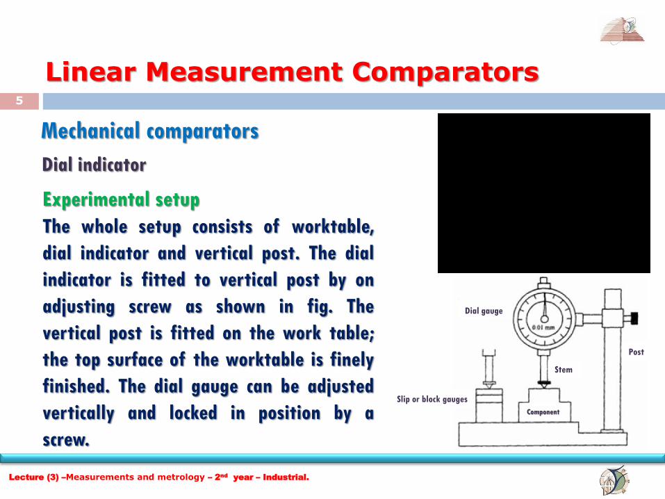
Mechanical comparators
Dial indicator
Dial gauge
Component
Stem
Slip or block gauges
Post
Experimental setup
The whole setup consists of worktable,
dial indicator and vertical post. The dial
indicator is fitted to vertical post by on
adjusting screw as shown in fig. The
vertical post is fitted on the work table;
the top surface of the worktable is finely
finished. The dial gauge can be adjusted
vertically and locked in position by a
screw.
Lecture (3) –Measurements and metrology – 2nd
year – Industrial.

6
Linear Measurement Comparators
Dial indicator
Procedure Let us assume that the required height of the component is
32.5mm. Initially this height is built up with slip gauges. The slip
gauge blocks are placed under the stem of the dial gauge. The
pointer in the dial gauge is adjusted to zero. The slip gauges are
removed. Now the component to be checked is introduced under
the stem of the dial gauge. If there is any deviation in the height
of the component, it will be indicated by the pointer
Mechanism The stem has rack teeth. A set of gears engage with the rack. The pointer is connected to a
small pinion. The small pinion is independently hinged. I.e. it is not connected to the stern.
The vertical movement of the stem is transmitted to the pointer through a set of gears. A
spring gives a constant downward pressure to the stem.
Lecture (3) –Measurements and metrology – 2nd
year – Industrial.

7
Linear Measurement Comparators
Read type mechanical comparator
Mechanical comparators
A spring loaded pointer is pivoted.
Initially, the comparator is set
with the help of a known
dimension. Set of slip gauges as
shown in fig. Then the indicator
reading is adjusted to zero. When
the part to be measured is kept
under the pointer, then the
comparator displays the deviation
of this dimension either in ± 01
side of the set dimension.
Lecture (3) –Measurements and metrology – 2nd
year – Industrial.
8
Linear Measurement Comparators
Mechanical comparators Advantages
1. It is usually robust, compact and easy to handle.
2. There is no external supply such as electricity, air required.
3. It has very simple mechanism and is cheaper when compared to other types.
4. It is suitable for ordinary workshop and also easily portable.
Disadvantages
1. Accuracy of the comparator mainly depends on the accuracy of the rack and
pinion arrangement. Any slackness will reduce accuracy.
2. It has more moving parts and hence friction is more and accuracy is less.
3. The range of the instrument is limited since pointer is moving over a fixed
scale.
Lecture (3) –Measurements and metrology – 2nd
year – Industrial.
9
Linear Measurement Comparators
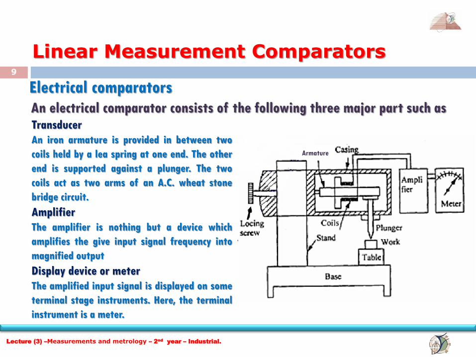
Electrical comparators
An electrical comparator consists of the following three major part such as Transducer
An iron armature is provided in between two
coils held by a lea spring at one end. The other
end is supported against a plunger. The two
coils act as two arms of an A.C. wheat stone
bridge circuit.
Amplifier
The amplifier is nothing but a device which
amplifies the give input signal frequency into
magnified output
Display device or meter
The amplified input signal is displayed on some
terminal stage instruments. Here, the terminal
instrument is a meter.
Armature
Lecture (3) –Measurements and metrology – 2nd
year – Industrial.
10
Linear Measurement Comparators
Electrical comparators
Checking accuracy
To check the accuracy of a given specimen or work, first a standard specimen is
placed under the plunger. After this, the resistance of wheat stone bridge is
adjusted so that the scale reading shows zero. Then the specimen is removed. Now,
the work is introduced under the plunger. If height variation of work presents, it
will move the plunger up or down. The corresponding movement of the plunger is
first amplified by the amplifier then it is transmitted to the meter to show the
variations. The least count of this electrical comparator is 0.001mm (one micron).
Lecture (3) –Measurements and metrology – 2nd
year – Industrial.

11
Linear Measurement Comparators
Electronic comparators
In electronic comparator, transducer induction or the principle of application of
frequency modulation or radio oscillation is followed.
Oscillator Amplifier Demodulator
Meter
Small A.C
signal
Large A.C
signal Direct
current
Transducer
Lecture (3) –Measurements and metrology – 2nd
year – Industrial.
12
Linear Measurement Comparators
Electronic comparators Transducer
It converts the movement of the plunger into an electrical signal. It is connected with oscillator.
Oscillator
The oscillator which receives electrical signal from the transducer and raises the amplitude of
frequency wave by adding carrier frequency called as modulation.
Amplifier
An amplifier is connected in between oscillator and demodulator. The signal coming out of the
oscillator is amplified into a required level.
Demodulator
Demodulator is nothing but a device which cuts off external carrier wave frequency. i.e. It
converts the modulated wave into original wave as electrical signal.
Meter
This is nothing but a display device from which the output can be obtained as a linear
measurement.
Lecture (3) –Measurements and metrology – 2nd
year – Industrial.