the use of speciality k-flute as a substitute for common
TRANSCRIPT

Western Michigan University Western Michigan University
ScholarWorks at WMU ScholarWorks at WMU
Paper Engineering Senior Theses Chemical and Paper Engineering
1996
The Use of Speciality K-Flute as a Substitute for Common Grades The Use of Speciality K-Flute as a Substitute for Common Grades
of Single Wall and Double Wall of Single Wall and Double Wall
Ron Pristash Western Michigan University
Follow this and additional works at: https://scholarworks.wmich.edu/engineer-senior-theses
Part of the Wood Science and Pulp, Paper Technology Commons
Recommended Citation Recommended Citation Pristash, Ron, "The Use of Speciality K-Flute as a Substitute for Common Grades of Single Wall and Double Wall" (1996). Paper Engineering Senior Theses. 439. https://scholarworks.wmich.edu/engineer-senior-theses/439
This Dissertation/Thesis is brought to you for free and open access by the Chemical and Paper Engineering at ScholarWorks at WMU. It has been accepted for inclusion in Paper Engineering Senior Theses by an authorized administrator of ScholarWorks at WMU. For more information, please contact [email protected].

The Use of Speciality K-Flute
as a Substitute For Common Grades of Single Wall and
Double Wall.
By Ron Pristash
A Thesis Submitted To Faculty of the Undergraguate College in Partial Fulfillment for a Baccalaureate Degree In Paper Science.
Advisor: Dr. Scheller
Sponsors: Arvco Container Corporation & Union Camp Corporation.
,.
;

Table of Contents
Abstract---------------------Pg 1
Historical Background--------Pg 2-8
Experimental Design----------pg 8-12
Results----------------------pg 13-22
Discussion of Results--------pg 23-28
Conlusion--------------------pg 28
Literature Cited-------------pg 29
Appendix--------.-------------pg 30-31
,

Abstract
This study exmines a new corrugated flute profile known
as "K" flute. The purpose of the study was to show that K
flute can maintain the same structual integrity and use
significantly less paper. . The main · tests performed were
tests for compression strength. Studiying the results of
compression testing, allows the designer to engineer the
corrugated container to meet the performance level required.
The study consists of two parts. The first part of the
study examines the effect of an increase in caliper has on
Edgwise Compresssion Testing (ECT) It was found that K
flute tested 5% stronger than A flute, 22% stronger than C
flute, 40% stronger than B flute. The next part of th study
compaired K flute as a subistute for commonly used grades of
singlewall and doublewall, the results of the comparison are
as follows: 2751b C vs 2001b K, the K flute tested 18% less
in compression strengh, used 61% less paper in the liner and
7. 6% more in the medium. In the next comparison, 2001b BC
vs 2001b K, the K flute tested 42% less in compression
strength, used 18% less paper in the liner and 80% less
paper in the medium. 2001b A vs 2001b K, the K flute tested
7% stronger in compression strength, it used 0% less paper
in the liner and 2% less paper in the medium. 2751b BC vs
44ECT K, the K flute tested 23% less in compresson strength,
K flute used 3.6% more paper in the liner and 80% less in
the medium.
Historical Introduction
The first fluted material closely related to the
present fluted member of corrugated board is believed to
have appeared in England on July 7, 1856, when a patent was
granted to Edward Charles Healy and Edwa-rd Ellis Allen. The
corrugated material was made by wetting the paper and
passing it between a heated pair of corrugated rollers. The
new invention did not receive credit for the development of
corrugated containers because very little progression seems
to have been made with the invention. (1)
The first patent for corrugated material that is
traceable to the present day, was patent no. 122,023 granted
on December 19,1871, to an American, Albert L. Jones. In
1874 Oliver Long received a patent for adding facings to
the corrugated. The Facings eliminated the undesirable
stretch experienced by the unlined corrugated material.
The fluted corrugated material was produced separately, and
one surface by brushing the facing with paste and then
applying the facing to the corrugated material. (1)
The first continuous corrugator was patented August 27,
1895 by Jefferson T. Ferres. Development of continuos
corrugators came rapidly; on December 9,1897 , Willam G.
Chapin applied for a patent on which is said to have been
2

the first practical machine for producing double face board
as a continuos operation. On Feburary 4, 1908 Samuel M.
Langston patented a double face corrugator that applied
certain new principals that are still in use today. The
Langston corrugator utilized a single facer together with a
double backer, yet each had independet control while
operating in tandem style. (1)
Figure 1 (10) shows the structure of single wall board .
It consists of a inside liner, out side liner and a
corrugated medium. This type of board is used in 90% of all
shipping applications. The strenght of the container is
varied by changing, the liner, medium, or by varing the
corrugation flute profile.
FIGURE 1 The Structure of Single, Double And Triple Wall
3
Outside Liner . Medium
Center Liner
M edium -----ln~ide Liner

Double wall, also shown in figure 1, is utilized when
higher compression strengths are needed, and to meet carrier
regulations for size and weight. There is also a combination
of 3 single wall layers known as triple wall. This type of
board is used mostly in severe duty government applications.
The flute profiles are shown in figure 2. The flutes
shown are actual size. It can be seen from figure 2 that the
flutes do not follow a particular size pattern
aplhebetacially.
FIGURE 2 Flute Height From Base To Peak
K-FLUTE
A-FLUTE
C-FLUTE
B-FLUTE
E-FLITTE
F-FLUTE
·-
·�•--.-----.---- • .=...
t • = !
4
-------~ «------

All flutes are named with a single alphebetical letter.
The alphebitical lettering is assigned chronologically, "A"
flute came first, then "B" and so on. New terminogly being
added is Jumbo flute which is "K" flute and micro flute
which is "F" flute. Figure 3, shows the make up of each
flute profile. A flute profile consists of: a take up
factor, number of flutes per inch, and the distance from
base to peak of the flute. The take up factor is the ratio
of the liner to the medium. For example, one lineal inch
(machine direction) of liner requires 1.585 lineal inches of
K fluted corrugated medium. The flutes per inch is the
frequency of the fluting. The height is the height from
base to peak for a particular flute. ( 9)
FIGURE 3 Flute Profiles
["11J]/j_fl);; Cl'ITJWllW;l li-ool ·� 'Il'm; lQ];l
!Lilm� l}@Q)Il' ffllI®Iffi'• [ � » w��
K-FL!ITE 30 .220 (7/32)tt 1. 585
A-FLU'fE 35.25 .188 (3/16 )tt 1. 614
C-FLU'fE 39 .145 (9/64)tt 1.03
B-FLlITE 47 .106 (7/64)tt 1. 381
E-FLlITE 90 .055 (7 /128) tt 1. 319--·-·-----
F-F'LlITE 128 .030 (1/32)tt 1. 224
5
I
I
-
I
'
I
---

The flute profile with the highest caliper in theory
should yeild the the greatest column strength. High flute
profiles yeild containers with high top-to-bottom crush
strengths. The high caliper also give the container the
lowest flat crush making the box best suited for
applications were a cushioning effect is required. (6)
The fluting with the lowest caliper in theory will have
the greatest resisitance to puncture. It will also have the
highest flat crush. Low caliper flute profiles are best
suited for applications wear less cushioning is needed and a
high resistance to damage of the container in handling is
desired. (6)
The micro flute profiles ("f" flute) are becoming very
popular with the fast food industry. This profile offers
the printability of folding carton while using significantly
less paper. ( 5)
A corrugated container serves 3 basic functions: 1) to
protect the contents 2) safe storage until the contents are
purchased 3) Provide advertising when printed .. The most
important is saftey. Since a container and its contents are
not in sight durring shipping, a set regulations were needed
6

to detertmine if damage to the contents are due to poor
handling by the carrier, a defect from the manufacture, or a
poorly designed container. (3)
Rule 41 is one of the 51 rules established in the
railroads Uniform Freight Classification (UFC) and is the
most rigorous of the material based rules. Rule 41 applies
to corrugated or solid fiberboard boxes. It appears as the
round certification stamp found on the outside of a box.
The rule specifies; 1) The maximum weight of the box
contents. 2) Maximum outside dimensions. 3) The minimum
combined weight of the facings. 4) The minimum bursting
test and 5) The minimum edge crush test. Figure 4, shows a
round certification stamp that conforms to rule 41.
Figure 4 Rule 41 Certifacition Stamp
7
I
THIS
SINGLEWALL OX MEETS ALL CONSTRUCTIO
REQUIREMENTS OF APPLICABLE FREIGHT CLASSIFICATION
200 MIN COMB 84 WT FACINGS
Item 222 is rules established by the National Motor
Freight Classification. It is similar to Rule 41 in its
requirements. These rules are very restrictive for the
creative designer. It was mentioned in the last paragraph
that changes in these rules are occurring. On January 21 of
1996, the National Classification Committee approved a new
rule designated Rule 180. This rule alllows shippers to use
any material or design for transport packaging used in the
less than truckload common carrier shipping.
There are 4 main reasons for the interest in the use of
new speciality flutes: 1) The use of quick-change single
facers has given the plants flexibility to run various flute
profiles with a minimal delay in production. 2) The use of
computer aided design programs and equipment, make design
with various flute profiles simple. See figures 3, it is a
CAD layout for a Regular Slotted Container. The allowances
for each profile are calculated immediately. 4). Constantly
changing rules and regulations that are giving designers
more freedom in designing. (5)
Experimental Design
This study looks into the use of specialty K-flute as a
possible replacement for various common grades of single and
8

double wall. The overall objective for this experiment is
to show that K-flute can develop similar structural
performance and use significantly less paper.
The main tests will be compression strength performance
testing. Examining compression strength tests gives the
designer the ability to be able to engineer his container by
controlling the amount of material and varying the flute
height.
# The first series of test involved using 200lbs K,A,C,
and B flutes. The liner (421b) and medium (261b) for each
of the samples was held constant. A 6x6 sample of each
grade was soaked apart and each liner and medium weighted to
ensure they are all the same weight. The only variable was
the flute height. The following tests will be performed;
edge-crush and top-to-bottom compression.
The Edge Crush Test (Figure 5) was performed following
TAPPI test #TS in a 22.2 C0/50% relative humidity
environment. Ten samples for each profile will be crushed
and an average value taken. Once the ECT tests are
performed, the McKee formula was then used to evaluate the
expected top-to-bottom compression strength. (4)&(1)
9
f

Figure 5 The Edge Crush Test
Edge Crush Test
Crush failure
Edgewise compression
(shorl column)
1-1 ;2 x 2-inch sample
The McKee formula is:
P= 5. 8 7 x ( Pm x {h x<z)
P= top-to-bottom compression strength of box
Pm = ECT Value
h= Caliper of board
z= perimeter of the box.
The next testing to be performed will be the full box
compression tests. Ten boxes were constructed for each
flute profile and allowed to condition for 24 hours at 22.2
C0/50% relative humidity. The size of the RSC's is 16 x 12
10
i ·----
... t

x 10. A regular slotted container has all flaps the same
depth. The two outer flaps, normally the lengthwise flaps,
are one-half the containers width (See Figure 6). The
lengthwise flaps meet at the center when the box is folded.
The RSC is the most commonly used box design in the
corrugated industry.
Figure 6 Layout For A Regular Slotted Container
Appi:-OVed BY�
Supcrcclles Design # L+S/16 X 1V
Customer:
UNION CAMP KALAMAZOO
CONTAINER SPEC
KALAMAZOO Ml
I I I I
r-
Salesperson : Bob Seo/IC11m111 ,,,,,,, Mar/29/96
Item # : RSC GI BC DIIV -�)csigncr: Bob Seo/I
���X-���_c_: RSCGWEIJ/NS{l)E _ ;!����f--:1-F-I-F-.1 ----1 -
Inside Dimensions: 16 12 10
"o"titsfiii:"ijlir1cnsions: --i<o112 : 12 "iii :- II ------ -l l I
Wt. : Blank Sizc:·sa�H- -;-- 22 7/8- _ KALAMAZO;:'��
(,J:'/(o
/0 J,\�
I I I I
n -- -1- - -r--- ---- -·
.. _q,.
I - I_ __
r-·--- _,r. .11,r. - - _____ l_ _ __,2 511r. _____
5�
51,� :_��,r.
�1,r. ______ L ____ ,2 31,r. ___
__ J
J, 112
11
--·- ---
- ------- -,-- - - ·--------- ···
-- -·· - 1- -- - ··- - - · - - - - · - - -- - - -·· -·- - . -
--- -- ---
---· . - -·------

The results from the above testing was analyzed, and
compared to the predicted values. A strength analysis was
then performed. The next series of test willl look into the
use of K-flute for replacing common grades of single, and
double wall. All of the testing done in the previous trials
will be performed on the new group; edge crush and top-to
bottom compression. All of the tests were performed
following TAPPI standards. 10 RSC's for each grad were
constructed and allowed to condition for 24 hours before
testing. For these tests, the strength, was the constant.
After testing a cost analysis of each comparison was
calculated.
The board comparisons will be as follows:
l) 2001b a vs 200 K
2) 275 lb c vs 2001b K
3) 2751b BC vs 44 ECT K
4) 2001b BC vs 2001b K
12
'
..

Results
14
.,

Experimental Predicted Top-
Top-to-Bottom to-Bottom
Flute ECT Compression Compression
Grade Profile (lb/in) (lb) (lb) Difference 275 BC 65.4 1623 1525 98
275 BC 66.3 1567 1525 42
275 BC 66.6 1605 1525 80
275 BC 66.1 1527 1525 2
275 BC 65.2 1553 1525 28
275 BC 66.3 1489 1525 -36
275 BC 65.9 1643 1525 118
275 BC 66.2 1584 1525 59
275 BC 66.4 1591 1525 66
275 BC 66.6 1673 1525 148
Average 66.1 1584
Standard
Deviation 0.5 23
15
•

I
Predicted Top-
# Experimental Top- to-Bottom
Flute ECT to-Bottom Compression
Grade Profile (lb/in) Compression (lb) (lb) Difference 200 BC 59.7 1346 1410 -64
200 BC 61.3 1423 1410 13
200 BC 60.8 1394 1410 -16
200 BC 61.4 1375 1410 -35
200 BC 61.6 1408 1410 -2
200 BC 61.3 1321 1410 -89
200 BC 62.3 1378 1410 -32
200 BC 60.6 1432 1410 22
200 BC 62.6 1573 1410 163
200 BC 61.8 1412 1410 2
Average 61.3 1386 -4
Standard
Deviation 0.8 36
16
t

Experimental
Top-to-Bottom Predicted Top-to-
Flute ECT Compression Bottom
Grade Profile (lb/in) (lb) Compression (lb) Difference
275 C 58.6 1172 1108 64
275 C 60.2 1385 1108 277
275 C 59.4 1131 1108 23
275 C 60.5 1146 1108 38
275 C 61.1 1038 1108 -70
275 C 59.1 1138 1108 30
275 C 59.3 1186 1108 78
275 C 59.6 1153 1108 45
275 C 59.9 1128 1108 20
275 C 60.3 1163 1108 55
Average 59.8 1152 29
Standard
Deviation 0.7 20
17
..
..

Predicted Top-, Experimental to-Bottom
ECT Top-to-Bottom Compression
Grade Flute Profile (lb/in) Compression (lb) (lb) Difference
44ECT K 55.6 1234 1410 -176
44ECT K 56.7 1109 1410 -301
44ECT K 54.7 1279 1410 -131
44ECT K 55.8 1323 1410 -87
44ECT K 57.1 1276 1410 -134
44ECT K 56.3 1278 1410 -132
44ECT K 56 1367 1410 -43
44ECT K 57.5 1334 1410 -76
44ECT K 56.9 1356 1410 -54
44ECT K 57.0 1297 1410 -113
Average 56.4 1287 -125
Standard
Deviation 0.8 71
18

Predicted
Experimental Top-to-
Top-to-Bottom Bottom
Average Compression Compression
Flute Profile ECT(lb/in) (lb) (lb) Difference A 45.3 917 903 14
A 45.3 887 903 -16
A 45.3 907 903 4
A 45.3 925 903 22
A 45.3 975 903 72
A 45.3 917 903 14
A 45.3 923 903 20
A 45.3 893 903 -10
A 45.3 931 903 28
A 45.3 926 903 23
Average 914 11
Standard
Deviation 15 15
19
..
'

,
Experimental Predicted Top-
Average Top-to-Bottom to-Bottom
Flute ECT Compression Compression
Profile (lb/in) (lb) (lb) Difference
B 43.7 696 676 20
B 43.7 701 676 25
B 43.7 692 676 16
B 43.7 687 676 11
B 43.7 679 676 3
B 43.7 685 676 9
B 43.7 704 676 28
B 43.7 691 676 15
B 43.7 733 676 57
B 43.7 694 676 18
Average 696 20
Standard
Deviation 15 15
20

Experimental Predicted Top-to-
Top-to-Bottom Bottom
Flute Average Compression Compression
Profile ECT (lb/in) (lb) (lb) Difference
C 43.7 809 776 33
C 43.7 789 776 13
C 43.7 791 776 15
C 43.7 817 776 41
C 43.7 794 776 18
C 43.7 802 776 26
C 43.7 798 776 22
C 43.7 791 776 15
C 43.7 634 776 -142
C 43.7 787 776 11
Average 798 22
Standard
Deviation 10 10
21
•
..

Predicted Top-
Average Experimental Top, to-Bottom
Flute ECT to-Bottom Compression
Profile (lb/in) Compression (lb) (lb) Difference
K 44.1 986 945 41
K 44.1 978 945 33
K 44.1 1010 945 65
K 44.1 917 945 -28
K 44.1 939 945 -6
K 44.1 981 945 36
K 44.1 897 945 -48
K 44.1 952 945 7
K 44.1 993 945 48
K 44.1 1084 945 139
Average 974 29
Standard
Deviation 53 53
22
.,

,
Discussion of Results
For the first part of the experiment, the effect of an
increase in caliper was examined in relation to the edge
test(ECT). It can be seen from the graph in figure 7, that
caliper had very little if any effect on ECT. The main
contributor to ECT is the liner weight. The average ECT
values were then used in the McKee formula to determine
perdicted values. It can be seen in figure 8, that caliper
has a significant role in box compression strength. The K
flute tested 5% stronger than the A flute, 22% stronger than
cl flute and 40% stronger than B flute. It can also be
noted how accurate the McKee formula is at predicting box
compression strength.
Figure 7
C 0 'iii UI -!�0. ..0
E =-o .co c,CII C UI CII 'i.:: CII ti)
Averagedgewise Compression Strength For Each
Flute Profile (2001b)
45.5
45
44.5
44
43.5
43
42.5
42
41.5
"A"
-Average Of Ten Trials,..
"B'' "C'
Flute Profile
23
"K''
■ "A"
■ "B"
■ "C'
O"K''
Cl "C w
41 •

•
Figure 8
Top-to-Bottom Compression 2001b (421b Liner and 261b Medium) -Average of Ten Trials-
1000
:c 900
.c 800
C CII 700
C 600 0
'iii
CII 500 0.
E 400 0
E 0
200
100 0.
0
0
"All 1181 "C' "K'
Flute Profile
The next part of the study examined using K-flute as a
substitute for various commonly used grades of single wall
and double wall. The first test was ECT. 10 samples were
cut and crushed and the values averaged. The predicted
values for top-to -bottom compression were calculated. The
regular slotted containers were then compressed and the
values were averaged. The goal was to fall within 10% of
the competitor in compression strength.
24
1§1 Experimental
■ Predicted
-i:i, ... -U)
I In VI ...
0
i: di 0 .,. t-

,,
The first comparison invloved 2001b A vs 2001b K. It
can be seen in figure 9, that the K-flute (974 ±531lbs)
tested 5% stronger than the A-flute (914 ±15lbs). The cost
analysis showed that K-flute used the same amount of liner
but used 2% less paper in the medium.
Figure 9
2001b K Flute vs. 2001b A Flute
900
J:i' -
940 C:
C:
0
'iii
0
200lb K 2001bA
Grade
25
950 - /
-Cl
t en --g-,-93)
Ill QI 920 -.... Q. E () 910 · /

,
The next compression was 2751b C vs. 2001b K. In figure 10,
it is shown that the K-flute came up short. The 2001b K-
flute (974 ±53lb) tested 18% less in compression strength
than the 2751b C flute (1152 ±20lbs). The cost analysis, if
K-flute would have been successful is 61% less paper in the
liner with only 7.6 more paper in the medium.
Figure 10
2751b C Flute vs. 2001b K Flute
1152
1200-
1150 //
.c 1100
1050 fl)
C: ?.A___
0
(I)
/(I) 1CXXJ
0
950-
900 /
850
275Ib C 200K
Grade
26
/ / -Ol
C / Q)
// Q) ... Q. // E (.) //
"
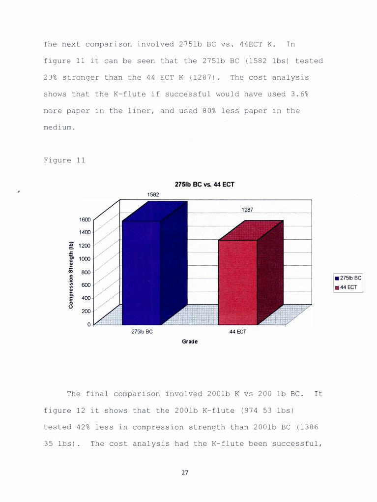
The next comparison involved 2751b BC vs. 44ECT K. In
figure 11 it can be seen that the 2751b BC (1582 lbs) tested
23% stronger than the 44 ECT K (1287). The cost analysis
shows that the K-flute if successful would have used 3.6%
more paper in the liner, and used 80% less paper in the
medium.
Figure 11
g 1200
f ;;; C:
0 ·;;;
f
E0
u
800
2751b BC vs. 44 ECT
1582
2751b BC 44ECT
Grade
The final comparison involved 2001b K vs 200 lb BC. It
figure 12 it shows that the 2001b K-flute (974 53 lbs)
tested 42% less in compression strength than 2001b BC (1386
35 lbs). The cost analysis had the K-flute been successful,
27
■2751b BC
■ 44 ECT
= Q C
.,, a.
D

it would have used 18% less paper in the liner and 80% less
paper in the medium.
Figure 12
2001b BC VS 200LB K
1400
I-1200
z
w
1000 I-
z 800 0
600
w
400
0 200 u
0
200 BC 200K
GRADE
Conclusion
Although, only in one of the comparisons did the K-flute
exceed its competitors in compression strength (2001b K vs
2001b A), the study was still a success and will be valuable
for future studies. Future studies could investigate the
use of various medium weights in the k-flute profile to
increase the compression strength closer to 10% goal. Also
Since the K Flute samples were made from one run, the
quality of the board may not be at peak performance levels.
28
a:: u,
cii u, a:: a.

"
Literature Cited
I) Setterholm, V.C., TAPPI 48 (5): 308 1965Leake, Craig., Corrugated Containers Conference, 1987.
2) Johnson, M., and Denniston, W. Paperboard Packaging 65(4): 98-108 (1980)
3) McKee, R. C. , Paperboard Packaging 79(9): 1963
4) Hyland, T., Paperboard Packaging 79(6): 34-38 (1994)
5) Koning, J. W., Jr., Compressive properties of linerboardas related to corrugated containers: Theoretical ModelVerification, TAPPI 61(8) :69 (1978).
6) Moody, R.C., Edgewise compression strength for corrugatedfiberboard as determined by local instableity. U.S. For.Serv. Res. Pup FPI 46, Madison Wis. (1963).
7) Kubat, J., and Sedivy, M. Preduction of the compressionstrength of corrugated boxes. Oblay 6, no.60, (1960).
8) Stott, R. A. Compression and stacking strength ofcorrugated fiberboard containers. Fiber containers 43, Sept (1959).
9) Maltenford. G. Compression strength of corrugatedcontainers. Parts I-IV. Fiber Containers 41, no.
7,9,10,11 (July, Sept, Oct, and Nov 1956).
lO)Smock, G.A., Handbook for pulp and Paper Technologists, Angus Wilde Productions 1992
29
,.

Appendix
30
•
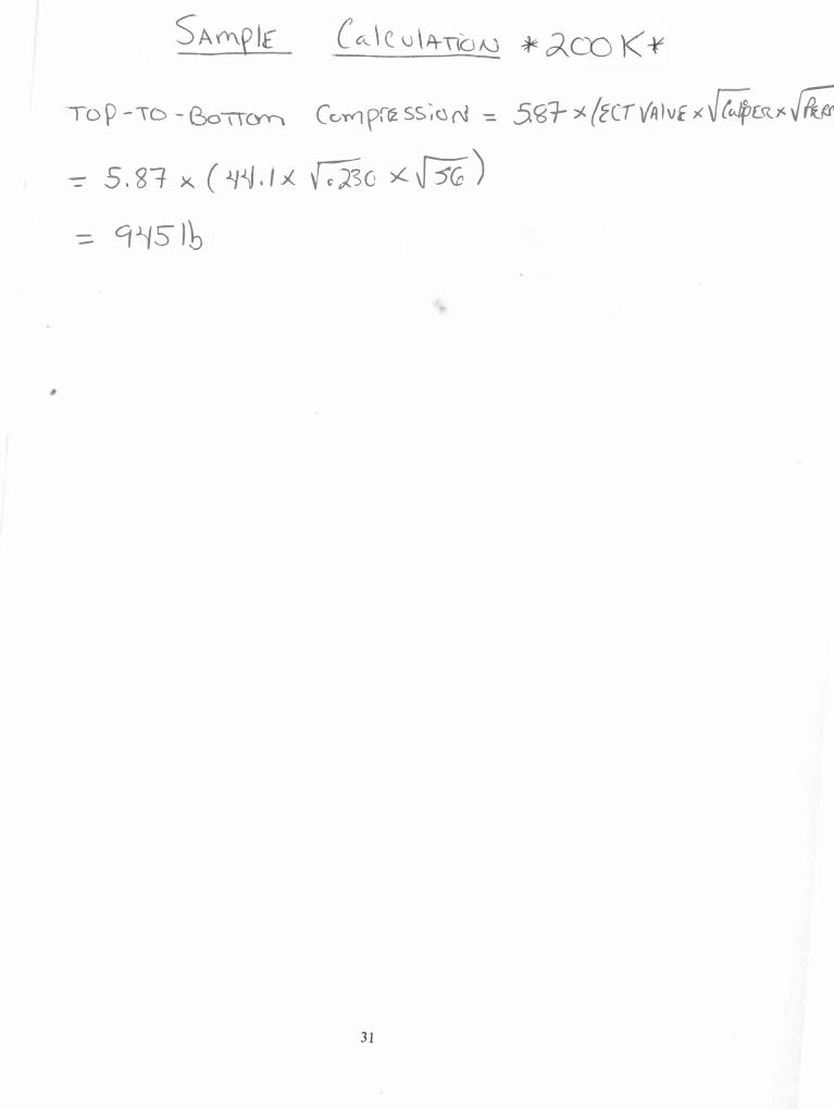
Top -ID - e,c>TTCl-'Y. c � priz ss; a r-l -= 5 �:i-- ;;1- {EC-r\(A Iv u � r alp&><�
--::- 5, 81- x ( -'}J,j , I .>( �G � � J
-::: 9�5 lb
31