the universal nail systemsynthes.vo.llnwd.net/o16/llnwmb8/int mobile/synthes... · 2019-03-05 ·...
TRANSCRIPT

SURGICAL TECHNIQUE
Instruments and implants approved by the AO Foundation.This publication is not intended for distribution in the USA.
THE UNIVERSAL NAIL SYSTEM
The-Universal-Nail-System_ST_DSEM-TRM-0116-0590-1.indd 1 12.10.16 14:27

Image intensifier control
This description alone does not provide sufficient background for direct use of DePuy Synthes products. Instruction by a surgeon experienced in handling these products is highly recommended.
Processing, Reprocessing, Care and MaintenanceFor general guidelines, function control and dismantling of multi-part instruments, as well as processing guidelines for implants, please contact your local sales representative or refer to:http://emea.depuysynthes.com/hcp/reprocessing-care-maintenanceFor general information about reprocessing, care and maintenance of Synthes reusable devices, instrument trays and cases, as well as processing of Synthes non-sterile implants, please consult the Important Information leaflet (SE_023827) or refer to: http://emea.depuysynthes.com/hcp/reprocessing-care-maintenance
The-Universal-Nail-System_ST_DSEM-TRM-0116-0590-1.indd 2 12.10.16 14:28

The Universal Nail System Surgical Technique DePuy Synthes 1
TABLE OF CONTENTS
INTRODUCTION The Universal Nails 2
TIBIAL NAILING TECHNIQUE Indications and Contraindications 4
Preoperative Considerations 5
Nail Insertion 8
Distal Locking 17
Proximal Locking 21
FEMORAL NAILING TECHNIQUE Indications 23
Preoperative Considerations 24
Nail Insertion 27
Distal Locking 33
Proximal Locking 35
SPECIAL TECHNIQUES Distal Locking with the Distal Aiming Device 39
Drilling in Two Steps 44
Removing the Threaded Conical Bolt 46
Extracting the Nail 48
IMPLANTS 50
Universal Femoral Nails 52
INSTRUMENTS 57
MRI INFORMATION 61
The-Universal-Nail-System_ST_DSEM-TRM-0116-0590-1.indd 1 12.10.16 14:28

2 DePuy Synthes The Universal Nail System Surgical Technique
THE UNIVERSAL NAILS
Universal Tibial and Femoral Nails feature:• Anatomic design facilitates insertion and improved fit• Transverse locking holes to allow use of one nail
in either left or right extremity• Conical threads for secure connection
to insertion/extraction instruments• Patented keystone* slot to prevent spreading of
proximal end when connected to instruments• Full length slot for flexibility• 1.3 mm wall thickness of 316L stainless steel
for strength with flexibility• Cloverleaf cross section facilitates interference
fit in the medullary canal• Multiple locking options
Universal Tibial Nail features:• Tapered distal tip to prevent penetration of posterior
cortex during insertion, and to glide easily through medullary canal
• One dynamic and two static transverse locking holes proximally
• Two transverse locking holes and additional AP locking hole distally
• Anatomically correct 11° bend1 and longer, flat proximal bend for correct insertion fit
• Beveled proximal end to prevent soft tissue irritation• Wide range of available sizes: 10 mm–14 mm
diameters and 255 mm–420 mm lengths
1 Heini PF. Untersuchung der Tibia-Innenform in Zusammenhang mit der Marknagelung. Dissertation. University of Bern, Switzerland; 1987.
* Keystone slot is covered under U.S. patent 4,628,920 and other patents.
The-Universal-Nail-System_ST_DSEM-TRM-0116-0590-1.indd 2 12.10.16 14:28

The Universal Nail System Surgical Technique DePuy Synthes 1
Universal Femoral Nail features:• Static and dynamic transverse locking holes proximally• Two static transverse locking holes distally• 1.5 m radius of curvature to approximate
the average anatomic curve of the femur2
• A wide range of available sizes: 10 mm–19 mm diameters and 300 mm–480 mm lengths
4.9 mm Locking Bolt features:• One diameter bolt for all applications using
universal nails• 4.9 mm thread diameter, engages bone and
nail for superior holding capacity• Fully-threaded shaft for easier insertion and extraction• 4.3 mm core diameter for greater strength• Low head profi le for areas with minimal soft
tissue coverage• Self-cutting trocar tip to eliminate tapping
2 Zuber K, Eulenberger J, Schneider E, Perren SM. “Anatomical curvature of the femoral canal for intramedullary roddings.” In: Biomechanics and Applied Research: Selected Proceedings of the 5th Meeting of the European Society of Biomechanics. 423–428. Berlin: Springer; 1987.
The-Universal-Nail-System_ST_DSEM-TRM-0116-0590-1.indd 3 12.10.16 14:28

4 DePuy Synthes The Universal Nail System Surgical Technique
TIBIAL NAILING TECHNIQUE
Indications:• Tibia fractures with bony support
(stable fracture in the middle third of the tibia, with or without locking):
• transverse fractures• short oblique fractures• pseudarthroses
Indications for Locking Technique Tibia fractures without bony support (unstable fractures in 60 % of the tibial length):• fractures near the metaphysis• long torsional fractures• segmental fractures• comminuted fractures• fractures with bone defects
Contraindications• No specific contraindications
INDICATIONS AND CONTRAINDICATIONS
The-Universal-Nail-System_ST_DSEM-TRM-0116-0590-1.indd 4 12.10.16 14:28

The Universal Nail System Surgical Technique DePuy Synthes 5
PREOPERATIVE CONSIDERATIONS
Although definitive nail length and diameter are deter-mined intraoperatively, nail selection should be part of the preoperative plan.
An approximate nail length is determined by measuring the patient from the knee joint to the ankle joint and subtracting 2 cm.
An approximate nail diameter is determined by measur-ing the isthmus of the affected medullary canal from an X-ray. If the isthmus is obliterated by the fracture pat-tern, a measurement is made from the contralateral side.
The Universal Tibial Nail Ruler, found in the Preoperative Planning Kit, may also be used to determine approximate nail size. The ruler depicts the nails 15 % larger than actual size, to compensate for the magnification which occurs when taking an X-ray at the standard tube-to-film distance of one meter. Placing the ruler directly over the preoperative X-ray of the uninjured leg provides an estimation of nail length and diameter.
Based on these measurements, a minimum of three diameters of nails in three lengths should be made avail-able for surgery.
NAIL SELECTION
The-Universal-Nail-System_ST_DSEM-TRM-0116-0590-1.indd 5 12.10.16 14:28
6 DePuy Synthes The Universal Nail System Surgical Technique
Preoperative Considerations
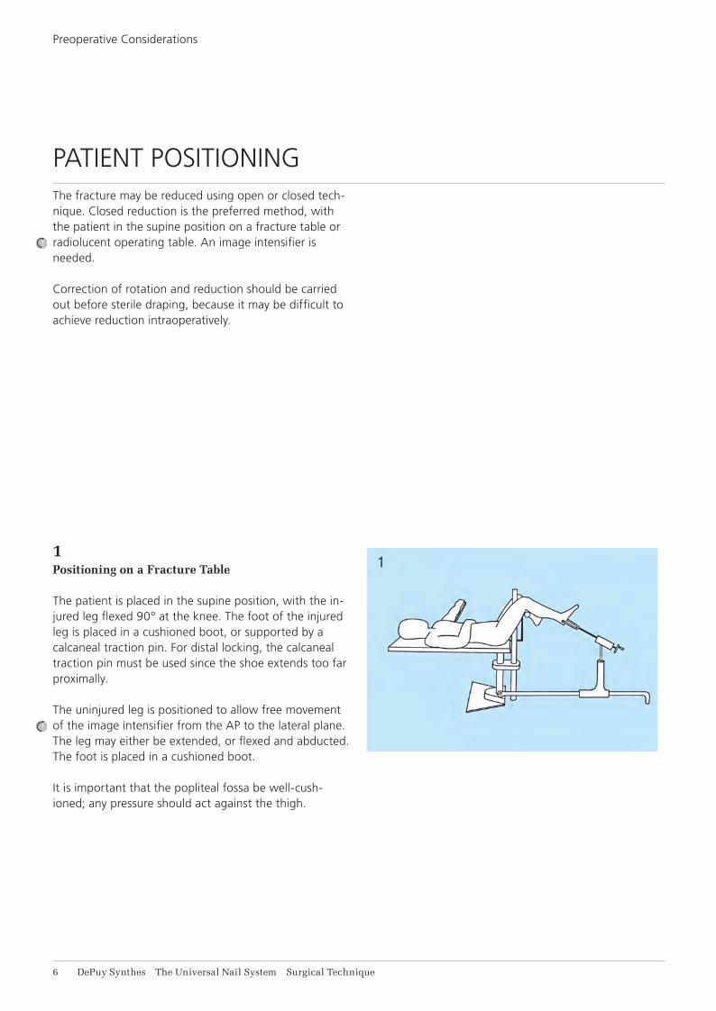
1Positioning on a Fracture Table
The patient is placed in the supine position, with the in-jured leg flexed 90° at the knee. The foot of the injured leg is placed in a cushioned boot, or supported by a calcaneal traction pin. For distal locking, the calcaneal traction pin must be used since the shoe extends too far proximally.
The uninjured leg is positioned to allow free movement of the image intensifier from the AP to the lateral plane. The leg may either be extended, or flexed and abducted. The foot is placed in a cushioned boot.
It is important that the popliteal fossa be well-cush-ioned; any pressure should act against the thigh.
PATIENT POSITIONINGThe fracture may be reduced using open or closed tech-nique. Closed reduction is the preferred method, with the patient in the supine position on a fracture table or radiolucent operating table. An image intensifier is needed.
Correction of rotation and reduction should be carried out before sterile draping, because it may be difficult to achieve reduction intraoperatively.
The-Universal-Nail-System_ST_DSEM-TRM-0116-0590-1.indd 6 12.10.16 14:28

The Universal Nail System Surgical Technique DePuy Synthes 7
Use of the Image IntensifierAn image intensifier is required for both closed reduc-tion and distal locking techniques. The image intensifier allows controlled viewing of the fracture zone for inser-tion of the reaming rod, medullary reamer heads and universal nail.
Proper positioning of the image intensifier is extremely important for locating the distal locking holes. With the patient in the supine position, the radiation source should be placed laterally to facilitate the aiming pro-cess, which is performed medially.
Note: The required working distance between the medial aspect of the tibia and the receiver is 47 cm.
2Positioning on a Standard Table
The operating table must be radiolucent. The patient is placed in the supine position. The injured leg is posi-tioned freely, with the knee flexed 90°. The uninjured leg is extended. The table should be adjusted to a com-fortable operating height for the surgeon.
The-Universal-Nail-System_ST_DSEM-TRM-0116-0590-1.indd 7 12.10.16 14:28

8 DePuy Synthes The Universal Nail System Surgical Technique
NAIL INSERTION
Entry PointSelecting the proper entry point is important to prevent rotation of the nail during insertion (especially with prox-imal metaphyseal fractures). The entry point should be over the midline of the medullary canal (in most pa-tients, slightly medial to the tibial tubercle) and as supe-rior as possible without causing damage to the anterior edge of the tibial plateau.
The-Universal-Nail-System_ST_DSEM-TRM-0116-0590-1.indd 8 12.10.16 14:28

The Universal Nail System Surgical Technique DePuy Synthes 9
Opening the Medullary Canal
Instruments
393.100 Universal Chuck with T-Handle
351.060 Centering Pin B 4.0 mm, length 400 mm, for No. 351.240
351.240 Cutter for UTN/CTN and for Universal Medullary Nail, B 11.0 mm, length 350 mm
351.260 Protection Sleeve, for No. 351.240
Make a longitudinal incision over the patellar tendon, and retract the tendon laterally. (In some patients, a pa-tellar tendon-splitting technique may be used to access the entry point.) Using the Universal Chuck with T-Han-dle, insert a 4.0 mm Centering Pin into the entry point. Pass it distally, angled 15° in the sagittal plane to the axis of the tibial shaft, into the proximal aspect of the medullary canal. A sterile nail may be placed against the anterior aspect of the tibial crest to act as a guide to the correct angle of insertion of the centering pin. Verify placement with the image intensifier. Pass the 11 mm Cannulated Cutter and Protection Sleeve over the pin. With the Protection Sleeve pressed against the bone, manually rotate the cutter to carve the opening into the medullary canal. Tighten the setscrew at the base of the cutter handle onto the pin, and remove the cannulated cutter, sleeve and centering pin.
Note: For pseudarthroses or hypertrophic non-unions, use the hand reamers sequentially to open the canal.
The-Universal-Nail-System_ST_DSEM-TRM-0116-0590-1.indd 9 12.10.16 14:28

11 DePuy Synthes The Universal Nail System Surgical Technique
Nail Insertion
Measuring for the NailOne of two methods can be used to measure for nail length:
a Determine the appropriate nail length by subtracting the exposed length of the reaming rod from its overall length of 950 mm. If using a calibrated reaming rod, read the appropriate nail length directly from the rod at the tibial entry point. If the measurement falls between two calibrated lengths, choose the shorter length nail.
Use the Radiographic Ruler after reduction or on the contralateral leg. Position the image intensifier for an AP view of the distal tibia. Holding the ruler with a long forceps, place it against the tibia with the distal tip at the level of the physeal scar, or at the desired nail depth; mark the skin at this point. Move the C-arm proximally to the level of the tibial plateau. Reposition the ruler against the tibia with the distal tip at the mark. Under image intensification, read the nail length directly from the ruler, choosing the nail length that is at or just below the level of the entry point.
Confirm the diameter of the selected nail with the Mea-suring Gauge.
Inserting the Reaming RodUnder image intensification, insert the 2.5 mm Reaming Rod into the canal, across the fracture site, and into the distal metaphysis. The Universal Chuck with T-Handle may be used to facilitate insertion. The Holding Forceps is used to control the reaming rod.
Reaming the Medullary CanalUse the SynReam Flexible Shaft with the front-cutting 8.5 mm Medullary Reamer Head to begin reaming. To protect the soft tissue, place the Tissue Protector poste-rior to the flexible shaft.
Reaming progresses in 0.5 mm increments using the interchangeable Medullary Reamer Heads.
The diameter of the nail to be used will match the diameter of the last reamer head used. Overreaming the medullary canal is not absolutely necessary.
Refer to the SynReam surgical technique DSEM/TRM/0614/0103 for further information.
The-Universal-Nail-System_ST_DSEM-TRM-0116-0590-1.indd 10 12.10.16 14:28

The Universal Nail System Surgical Technique DePuy Synthes 11
Measuring for the NailOne of two methods can be used to measure for nail length:
a Determine the appropriate nail length by subtracting the exposed length of the reaming rod from its overall length of 950 mm. If using a calibrated reaming rod, read the appropriate nail length directly from the rod at the tibial entry point. If the measurement falls between two calibrated lengths, choose the shorter length nail.
Use the Radiographic Ruler after reduction or on the contralateral leg. Position the image intensifier for an AP view of the distal tibia. Holding the ruler with a long forceps, place it against the tibia with the distal tip at the level of the physeal scar, or at the desired nail depth; mark the skin at this point. Move the C-arm proximally to the level of the tibial plateau. Reposition the ruler against the tibia with the distal tip at the mark. Under image intensification, read the nail length directly from the ruler, choosing the nail length that is at or just below the level of the entry point.
Confirm the diameter of the selected nail with the Mea-suring Gauge.
The-Universal-Nail-System_ST_DSEM-TRM-0116-0590-1.indd 11 12.10.16 14:28

12 DePuy Synthes The Universal Nail System Surgical Technique
Nail Insertion
Assembling the Insertion Instrumentation
The Insertion Handle
Instruments
355.470 Nut, knurled, for Tibial Medullary Nails B 10.0 to 14.0 mm
355.440 Threaded Bolt, conical, for Tibial Medullary Nails B 10.0 to 14.0 mm
355.410 Insertion Handle, for Tibial Medullary Nails B 9.0 to 14.0 mm
The Insertion Handle guides the nail and controls rota-tion during insertion. Although the Insertion Handle is usually oriented medially throughout the procedure, it may be rotated laterally (180°) for easier insertion. If the nail is to be locked, the Insertion Handle must be oriented medially; it is then used as an aiming device for inserting the medial-to-laterally placed proximal locking bolts.
The-Universal-Nail-System_ST_DSEM-TRM-0116-0590-1.indd 12 12.10.16 14:28

The Universal Nail System Surgical Technique DePuy Synthes 11
Standard Insertion Assembly
Instruments
355.180 Driving Head
355.160 Driving Piece, curved
1Slide the tibial nail over the 2.5 mm Reaming Rod (A). Manually insert the nail into the medullary canal as far as possible.
2Orient the Insertion Handle (B) medially on the nail. The tabs of the Insertion Handle must engage the position-ing notches of the nail.
3Pass the Threaded Conical Bolt (C) through the Insertion Handle, and screw into the proximal end of the nail.
Note: Unlike the Universal Femoral Nail instrumen-tation, the conical bolt cannot be threaded into the Universal Tibial Nail before the Insertion Handle is in position. The conical bolt must be placed through the Insertion Handle first.
4Tighten the conical bolt with the Combination Wrench or Cannulated Socket Wrench. Do not overtighten. Mount the Locking Nut (D) onto the conical bolt, and tighten the nut with the 4.5 mm Pin Wrench.
Standard Insertion Assembly
The-Universal-Nail-System_ST_DSEM-TRM-0116-0590-1.indd 13 12.10.16 14:28

14 DePuy Synthes The Universal Nail System Surgical Technique
Inserting the NailUsing the 700 g Hammer (or Ram assembly), drive the nail into the canal with measured blows. The image intensifier should be used to monitor the passage of the nail across the fracture site. Control rotation of the nail using the Insertion Handle.
Note: If the nail is rotating, the Insertion Handle may be placed laterally for increased guidance and control. Loosen the Locking Nut, and disengage the Insertion Handle from the positioning notches of the nail. Rotate the Insertion Handle 180°, taking care to re-engage the Insertion Handle’s tabs with the nail’s positioning notches. Tighten down the Lock-ing Nut with the pin wrench and retighten as neces-sary during nail insertion.
The nail should advance into the medullary canal with each blow of the Hammer. If resistance is encountered, remove the nail and ream the canal an additional 0.5 mm. Reinsert the nail.
As the bend in the nail passes the insertion point, the surgeon will feel a release of tension. Insert the proximal nail end below the bone surface. When the nail is fully seated, remove the Curved Driving Piece and Driving Head (or Ram assembly) and reaming rod.
Nail Insertion
5Mount the Driving Head (E) onto the Curved Driving Piece (F). Unscrew the knurled threaded sleeve until a thread end is visible. This will allow the driving piece to be positioned over the hex head of the conical bolt. The Curved Driving Piece must be positioned so it allows the driving force to be transmitted parallel to the long axis of the tibia, (i.e., parallel to the distal portion of the nail). Screw in the knurled threaded sleeve to secure the coni-cal bolt in the driving piece.
Note: When tightening the Curved Driving Piece, leave 3 mm of clearance between the Curved Driv-ing Piece and the first thread of the conical bolt. This will eliminate the chance of damaging the proximal threads of the conical bolt during nail in-sertion.
Alternate Insertion Assembly
Alternate Insertion AssemblyThe Ram Guide (G) and Ram (H) may also be used to in-sert the Universal Tibial Nail. Follow steps 1–4 (on the previous page), then screw the Curved Driving Piece with the Ram Guide onto the Threaded Conical Bolt. Slide the Ram over the Ram Guide, and screw the Grip (not shown) onto the upper end of the Ram Guide.
The-Universal-Nail-System_ST_DSEM-TRM-0116-0590-1.indd 14 12.10.16 14:28

The Universal Nail System Surgical Technique DePuy Synthes 15
Inserting the NailUsing the 700 g Hammer (or Ram assembly), drive the nail into the canal with measured blows. The image intensifier should be used to monitor the passage of the nail across the fracture site. Control rotation of the nail using the Insertion Handle.
Note: If the nail is rotating, the Insertion Handle may be placed laterally for increased guidance and control. Loosen the Locking Nut, and disengage the Insertion Handle from the positioning notches of the nail. Rotate the Insertion Handle 180°, taking care to re-engage the Insertion Handle’s tabs with the nail’s positioning notches. Tighten down the Lock-ing Nut with the pin wrench and retighten as neces-sary during nail insertion.
The nail should advance into the medullary canal with each blow of the Hammer. If resistance is encountered, remove the nail and ream the canal an additional 0.5 mm. Reinsert the nail.
As the bend in the nail passes the insertion point, the surgeon will feel a release of tension. Insert the proximal nail end below the bone surface. When the nail is fully seated, remove the Curved Driving Piece and Driving Head (or Ram assembly) and reaming rod.
The-Universal-Nail-System_ST_DSEM-TRM-0116-0590-1.indd 15 12.10.16 14:28

16 DePuy Synthes The Universal Nail System Surgical Technique
Removing the Threaded Conical Bolt
Instruments
355.470 Nut, knurled, for Tibial Medullary Nails B 10.0 to 14.0 mm
355.440 Threaded Bolt, conical, for Tibial Medullary Nails B 10.0 to 14.0 mm
355.410 Insertion Handle, for Tibial Medullary Nails B 9.0 to 14.0 mm
If the nail will not be locked proximally, remove the Insertion Handle assembly. Use the pin wrench to loosen the Locking Nut one-half turn. While holding the Inser-tion Handle firmly, remove the conical bolt with the Combination Wrench or the Cannulated Socket Wrench.
Note: These instructions must be followed to prevent cross-threading of the conical bolt in the nail. See “Special Techniques,” page 46, for more informa-tion.
If the nail will be locked, the Insertion Handle, Threaded Conical Bolt and Locking Nut remain on the nail. The Insertion Handle must be oriented medially to place the proximal locking bolts, and should be reoriented to that position if necessary.
Nail Insertion
The-Universal-Nail-System_ST_DSEM-TRM-0116-0590-1.indd 16 12.10.16 14:28

The Universal Nail System Surgical Technique DePuy Synthes 17
DISTAL LOCKING
Several distal locking technique options are available to the surgeon. The Radiolucent Drive provides a conve-nient technique for targeting and drilling the distal lock-ing holes. The Radiolucent Drive reduces the working distance from the incision, offers less restricted position-ing when using the image intensifier, and reduces opera-tive time.
Alternatively, the locking technique with the Distal Aiming Device requires a minimum working distance of 47 cm between the receiver and the patient’s leg; see page 39. If less working distance is available, see the alternative drilling technique (“Drilling in Two Steps”) on page 44. As a further option, the 4.0 mm/4.5 mm Drill Bit (355.900) may be used to drill for distal locking in the standard freehand fashion.
The distal holes are locked first to maintain limb length and control rotation of the distal fragment.
The Universal Tibial Nail has three distal locking holes. Two holes are oriented mediolaterally (ML), and one hole is oriented anteroposteriorly (AP). Usually, locking is accomplished with two bolts, inserted medial to lateral. The chart below offers other locking options for special circumstances.
The-Universal-Nail-System_ST_DSEM-TRM-0116-0590-1.indd 17 12.10.16 14:28

18 DePuy Synthes The Universal Nail System Surgical Technique
Distal Locking with the Radiolucent DriveThe Radiolucent Drive works with the image intensifier to target and drill the distal locking holes.
1Align the image intensifier with the most distal hole in the nail. Adjust until a perfect circle is visible (Fig. A).
Distal Locking
2Under image intensification, place a scalpel on the skin with the tip of the blade over the center of the hole to determine the stab incision point. Make a stab incision (Fig. B).
3Insert the special 4.0 mm Three-Fluted Drill Bit (511.417) into the Radiolucent Drive. Under image intensification, place the tip of the drill bit oblique to the X-ray beam, into the stab incision and onto the tibia, until the tip of the drill bit is centered in the locking hole image (Fig. C).
Distal Locking Combination Options
Special Circumstances Proximal ML Hole
AP Hole
Distal ML Hole
Insufficient soft tissue coverage of most distal locking bolt head
X X
Distal fractures X X
Insufficient soft tissue coverage of both medial locking bolt heads (comminuted midshaft fractures only)
X
The-Universal-Nail-System_ST_DSEM-TRM-0116-0590-1.indd 18 12.10.16 14:28

A A
B
C
The Universal Nail System Surgical Technique DePuy Synthes 19
Distal Locking with the Radiolucent DriveThe Radiolucent Drive works with the image intensifier to target and drill the distal locking holes.
1Align the image intensifier with the most distal hole in the nail. Adjust until a perfect circle is visible (Fig. A).
Incorrect position Correct position
2Under image intensification, place a scalpel on the skin with the tip of the blade over the center of the hole to determine the stab incision point. Make a stab incision (Fig. B).
3Insert the special 4.0 mm Three-Fluted Drill Bit (511.417) into the Radiolucent Drive. Under image intensification, place the tip of the drill bit oblique to the X-ray beam, into the stab incision and onto the tibia, until the tip of the drill bit is centered in the locking hole image (Fig. C).
The-Universal-Nail-System_ST_DSEM-TRM-0116-0590-1.indd 19 12.10.16 14:28

D
21 DePuy Synthes The Universal Nail System Surgical Technique
4Tilt the drive until the drill bit is in line with the X-ray beam and appears as a radiopaque solid circle in the center of the outer ring. The drill bit will nearly fill in the locking hole image. Hold the drill firmly in this position and drill through both cortices. Use image intensification to keep the drill bit centered in the outer ring through-out the drilling process (Fig. D).
5Measure the hole with the Depth Gauge for locking bolts. Add 2 mm to this reading to ensure that the lock-ing bolt will engage the far cortex. Insert the locking bolt and tighten with the hexagonal screwdriver.
6Reposition the image intensifier to align with the second selected hole (the second ML hole or the AP hole). Re-peat steps 1 through 5 to insert a second distal locking bolt.
Distal Locking
The-Universal-Nail-System_ST_DSEM-TRM-0116-0590-1.indd 20 12.10.16 14:28
The Universal Nail System Surgical Technique DePuy Synthes 21
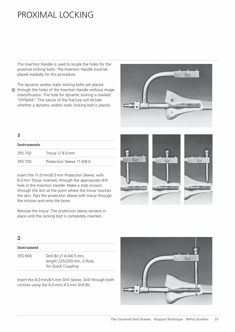
PROXIMAL LOCKING
The Insertion Handle is used to locate the holes for the proximal locking bolts. The Insertion Handle must be placed medially for this procedure.
The dynamic and/or static locking bolts are placed through the holes of the Insertion Handle without image intensification. The hole for dynamic locking is marked “DYNAM.” The nature of the fracture will dictate whether a dynamic and/or static locking bolt is placed.
1
Instruments
355.750 Trocar B 8.0 mm
355.700 Protection Sleeve 11.0/8.0
Insert the 11.0 mm/8.0 mm Protection Sleeve, with 8.0 mm Trocar inserted, through the appropriate drill hole in the Insertion Handle. Make a stab incision through the skin at the point where the trocar touches the skin. Pass the protection sleeve with trocar through the incision and onto the bone.
Remove the trocar. The protection sleeve remains in place until the locking bolt is completely inserted.
2
Instrument
355.900 Drill Bit B 4.0/4.5 mm, length 225/200 mm, 2-flute, for Quick Coupling
Insert the 8.0 mm/4.5 mm Drill Sleeve. Drill through both cortices using the 4.0 mm/ 4.5 mm Drill Bit.
The-Universal-Nail-System_ST_DSEM-TRM-0116-0590-1.indd 21 12.10.16 14:28

22 DePuy Synthes The Universal Nail System Surgical Technique
3
Instrument
355.790 Depth Gauge for Locking Bolts, measuring range up to 90 mm
Remove the drill sleeve. Using the Depth Gauge for lock-ing bolts, measure for the proper length 4.9 mm Locking Bolt. Add 2 mm to the measurement to ensure engage-ment of the far cortex.
Note: If using a calibrated drill bit, stop the drill after drilling through the far cortex. If necessary, use the image intensifier to confirm the position of the drill bit. Press the drill and protection sleeves firmly against the bone and read the correct bolt length on the calibrated drill bit at the end of the 8.0 mm/4.5 mm Drill Sleeve (see inset). Remove the drill sleeve.
4Insert the locking bolt through the 11.0 mm/8.0 mm Protection Sleeve.
If an additional proximal locking bolt is to be placed, repeat steps 1 through 4.
Removing the Insertion InstrumentsRemove the Insertion Handle assembly. Use the pin wrench to loosen the Locking Nut one-half turn. While holding the Insertion Handle firmly, remove the conical bolt with the Combination Wrench or the Cannulated Socket Wrench.
Note: The conical bolt must be removed properly to prevent cross-threading and jamming of the conical bolt in the nail. See “Special Techniques,” page 46, for more information.
Proximal Locking
The-Universal-Nail-System_ST_DSEM-TRM-0116-0590-1.indd 22 12.10.16 14:28

The Universal Nail System Surgical Technique DePuy Synthes 21
FEMORAL NAILING TECHNIQUE
Femur fractures with bony support (stable fracture in the middle third of the femur, with or without locking):• transverse fractures• short oblique fractures• pseudarthroses
Indications for Locking Technique Femur fractures without bony support (unstable fracture in 60% of the femoral length):• fractures near the metaphysis• long torsional fractures• segmental fractures• comminuted fractures• fractures with bone defects
INDICATIONS
The-Universal-Nail-System_ST_DSEM-TRM-0116-0590-1.indd 23 12.10.16 14:28

24 DePuy Synthes The Universal Nail System Surgical Technique
PREOPERATIVE CONSIDERATIONS
Although definitive nail length and diameter are deter-mined intraoperatively, nail selection should be part of the preoperative plan.
An approximate nail length is determined by measuring the patient from the tip of the greater trochanter to the knee joint space and subtracting 2 cm.
An approximate nail diameter is determined by measur-ing the isthmus of the affected medullary canal from an X-ray. If the isthmus is obliterated by the fracture pat-tern, a measurement is made from the contralateral side.
The Universal Femoral Nail Ruler, found in the Preopera-tive Planning Kit, may also be used to determine approxi-mate nail size. The ruler depicts the nails 15 % larger than actual size, to compensate for the magnification which occurs when taking an X-ray at the standard tube-to-film distance of one meter. Placing the ruler directly over the preoperative X-ray of the uninjured leg provides an estimation of nail length and diameter.
Based on these measurements, a minimum of three diameters of nails in three lengths should be available for surgery.
NAIL SELECTION
The-Universal-Nail-System_ST_DSEM-TRM-0116-0590-1.indd 24 12.10.16 14:28

The Universal Nail System Surgical Technique DePuy Synthes 25
1 Lateral Positioning on a Fracture Table
A fracture table with long cantilevers is used. The patient is placed in a lateral decubitus position. The pelvis is held vertical with the supports on each side of the table. The patient is slid downwards on the table until the perineum rests on a well-cushioned perineal post.
A traction pin is placed in the intercondylar area of the injured leg to apply traction and aid reduction. The foot of the injured leg is placed in a boot. The uninjured leg is flexed at the hip and knee, and supported by a brace. The uninjured leg should be externally rotated to allow the image intensifier to be adjusted freely.
2 Supine Positioning on a Fracture Table
With the patient in the supine position, the leg of the in-jured femur is allowed to hang with the knee flexed 90°. The patient’s pelvis should be positioned flat, providing correct rotational alignment of the femur. To allow ac-cess to the proximal femur, either adduct the injured leg, or shift the torso to the uninjured side, while keeping the pelvis flat. The uninjured leg is placed in a support.
The fracture may be reduced using open or closed tech-nique. Closed reduction is the preferred method, with the patient positioned on a fracture table or radiolucent operating table; an image intensifier is needed. Correc-tion of rotation and reduction should be carried out before sterile draping, because it is difficult to achieve reduction intraoperatively.
PATIENT POSITIONING
The-Universal-Nail-System_ST_DSEM-TRM-0116-0590-1.indd 25 12.10.16 14:28

26 DePuy Synthes The Universal Nail System Surgical Technique
4 Supine Positioning on a Standard Table
The operating table must be radiolucent. The patient is placed in a supine position. To allow access to the proxi-mal femur, the uninjured leg is abducted as far as possi-ble, and the injured leg is adducted. The Large Distractor is used to aid reduction and correct rotational alignment.
Use of the Image IntensifierAn image intensifier is required for both closed reduc-tion and distal locking techniques. The image intensifier allows controlled viewing of the fracture zone for inser-tion of the reaming rod, medullary reamer heads, and universal nail.
Proper positioning of the image intensifier is extremely important for locating the distal locking holes. With the patient in the lateral decubitus or supine position, the ra-diation source should be placed on the medial aspect of the femur. This will facilitate the aiming process, which is performed laterally.
Note: The minimum required working distance between the lateral aspect of the femur and the receiver is 47 cm.
3 Lateral Positioning on a Standard Table
The operating table must be radiolucent. The patient is placed in a lateral position (a vacuum mattress may be helpful for this purpose). The injured leg is flexed for-ward 45°, and with the knee bent 90°, is placed over the uninjured leg. The Large Distractor is used to aid reduc-tion and correct rotational alignment.
Preoperative Considerations
The-Universal-Nail-System_ST_DSEM-TRM-0116-0590-1.indd 26 12.10.16 14:28

The Universal Nail System Surgical Technique DePuy Synthes 27
NAIL INSERTION
Entry PointSelecting the proper entry point is important to prevent complications during nail insertion. This entry point dif-fers from that of the original AO ASIF nail. Because the universal nail is slightly stiffer and more curved than the original nail, the insertion point must be in line with the medullary canal. Studies of the geometry of the medul-lary canal show that the ideal entry point is immediately in or just posterolateral to the piriformis fossa.
Opening the Medullary Canal
Instruments
393.100 Universal Chuck with T-Handle
351.240 Cutter for UTN/CTN and for Universal Medullary Nail, B 11.0 mm, length 350 mm
351.260 Protection Sleeve, for No. 351.240
Make a longitudinal incision proximal to the greater trochanter. Either the 11.0 mm Cannulated Cutter or the awl can be used to open the medullary canal.
If the 11 mm Cannulated Cutter is used, assemble the 4 mm Centering Pin in the Universal Chuck with T-Han-dle. Place the tip of the pin at the correct entry point. Rotate the centering pin to penetrate the medullary ca-nal. Verify placement with image intensification. Remove the universal chuck.
The-Universal-Nail-System_ST_DSEM-TRM-0116-0590-1.indd 27 12.10.16 14:28

28 DePuy Synthes The Universal Nail System Surgical Technique
Inserting the Reaming RodUnder image intensification, insert the 2.5 mm Reaming Rod into the canal, across the fracture site, and into the distal metaphysis. The Universal Chuck with T-Handle may be used to facilitate insertion. The Holding Forceps is used to control the reaming rod.
Pass the 11 mm Cannulated Cutter and Protection Sleeve over the centering pin. Rotate the cannulated cutter and open the medullary canal to a minimum depth of 5 cm. (Image intensification may be required.) When the canal is penetrated, fix the centering pin in the cannulated cut-ter by tightening the setscrew at the base of the handle. Remove the cannulated cutter/centering pin assembly.
If the awl is used, place its tip at the correct entry point, and turn it to open the medullary canal.
Note: For pseudarthroses or hypertrophic non-unions, use hand reamers sequentially to open the canal.
Nail Insertion
The-Universal-Nail-System_ST_DSEM-TRM-0116-0590-1.indd 28 12.10.16 14:28

The Universal Nail System Surgical Technique DePuy Synthes 29
Reaming the Medullary CanalUse the SynReam Flexible Shaft with the front-cutting 8.5 mm Medullary Reamer Head to begin reaming. To protect the soft tissue, place the Tissue Protector medial to the flexible shaft.
Reaming progresses in 0.5 mm increments using the interchangeable Medullary Reamer Heads.
The diameter of the nail to be used will match the diam-eter of the last reamer used. Overreaming the medullary canal by 0.5 mm–1.0 mm facilitates nail insertion but is not absolutely necessary.
Refer to the SynReam surgical technique DSEM/TRM/0614/0103 for further information.
Measuring for the NailDetermine the appropriate nail length by subtracting the exposed length of the reaming rod from its overall length of 950 mm. Confirm the diameter of the selected nail with the Measuring Gauge. If using a calibrated reaming rod, read the appropriate nail length directly from the rod at the femoral entry point. If the measure-ment falls between two calibrated lengths, choose the shorter length nail.
The-Universal-Nail-System_ST_DSEM-TRM-0116-0590-1.indd 29 12.10.16 14:28

11 DePuy Synthes The Universal Nail System Surgical Technique
Nail Insertion
Assembling the Insertion Instrumentation
Instruments
355.490 Insertion Handle, for Femoral Medullary Nails B 9.0 to 12.0 mm
355.500 Insertion Handle, for Femoral Medullary Nails B 13.0 to 16.0 mm
355.510 Insertion Handle, for Femoral Medullary Nails B 17.0 to 19.0 mm
355.570 Nut, knurled, for Femoral Medullary Nails B 9.0 to 12.0 mm
355.580 Nut, knurled, for Femoral Medullary Nails B 13.0 to 16.0 mm
or
355.590 Nut, knurled, for Femoral Medullary Nails B 17.0 to 19.0 mm
355.530 Threaded Bolt, conical, for Femoral Medullary Nails B 9.0 to 12.0 mm
355.540 Threaded Bolt, conical, for Femoral Medullary Nails B 13.0 to 16.0 mm
355.500 Insertion Handle, for Femoral Medullary Nails B 13.0 to 16.0 mm
The Insertion HandleThe Insertion Handle guides the nail and controls rota-tion during insertion. If the nail is locked, the Insertion Handle is also used as an aiming device for inserting the proximal locking bolts.
The-Universal-Nail-System_ST_DSEM-TRM-0116-0590-1.indd 30 12.10.16 14:28

F
D
C
A
B
E
The Universal Nail System Surgical Technique DePuy Synthes 11
Standard Insertion Assembly
Instruments
355.280 Handle, for No. 355.220
355.220 Hammer Guide, cannulated, for Universal Medullary Nails
355.250 Ram
1Slide the femoral nail over the 2.5 mm Reaming Rod. Manually insert the nail into the medullary canal as far as possible.
2Screw the Threaded Conical Bolt (A) into the proximal end of the nail. Pass the Insertion Handle (B) over the bolt. Be sure to use the conical bolt and Insertion Handle that correspond to the diameter of the nail to be in-serted. The Insertion Handle should be oriented laterally, and its tabs must engage the positioning notches of the nail.
3Using the Insertion Handle to control nail rotation, tighten the conical bolt with the Combination Wrench or Cannulated Socket Wrench. Mount the appropriate Locking Nut (C) onto the conical bolt, and tighten with the 4.5 mm Pin Wrench.
4Pass the Ram Guide (D) over the guide rod, and screw it onto the proximal end of the conical bolt. Slip the Ram (E) over the Ram Guide and screw the Grip (F) onto the upper end of the Ram Guide.
The-Universal-Nail-System_ST_DSEM-TRM-0116-0590-1.indd 31 12.10.16 14:28

12 DePuy Synthes The Universal Nail System Surgical Technique
1Align the image intensifier with the most distal hole in the nail. Adjust until a perfect circle is visible (Fig. A).
2Under image intensification, place a scalpel on the skin with the tip of the blade over the center of the hole to determine the stab incision point. Make a stab incision (Fig. B).
3Insert the special 4 mm Three-Fluted Drill Bit (511.417) into the Radiolucent Drive. Under image intensification, place the tip of the drill bit oblique to the X-ray beam, into the stab incision and onto the femur, until the tip of the drill bit is centered in the locking hole (Fig. C).
Inserting the NailWith controlled blows of the Ram, insert the nail into the canal. To prevent the guide rod from backing out, the Guide Rod Retainer may be inserted into the Ram Guide. Image intensification should be used to monitor the passage of the nail across the fracture. Control rota-tion of the nail using the Insertion Handle.
The nail should advance in the medullary canal with each blow of the Ram. If resistance is encountered, re-move the nail and ream the canal an additional 0.5 mm to 1 mm.
When the nail is fully seated, remove the Ram Guide Assembly and guide rod.
Removing the Threaded Conical BoltIf the nail will not be locked, remove the Insertion Han-dle assembly. Use the pin wrench to loosen the Locking Nut one-half turn. While holding the Insertion Handle firmly, remove the conical bolt with the Combination Wrench or the Cannulated Socket Wrench.
Note: These instructions must be followed to prevent cross-threading of the conical bolt in the nail. See “Special Techniques,” page 46, for more informa-tion.
If the nail will be locked, the Insertion Handle, Threaded Conical Bolt and Locking Nut remain on the nail.
Nail Insertion
The-Universal-Nail-System_ST_DSEM-TRM-0116-0590-1.indd 32 12.10.16 14:28

A A
B
C
The Universal Nail System Surgical Technique DePuy Synthes 11
DISTAL LOCKING
Distal Locking with the Radiolucent DriveThe Radiolucent Drive works with the image intensifier to target and drill the distal locking holes.
1Align the image intensifier with the most distal hole in the nail. Adjust until a perfect circle is visible (Fig. A).
2Under image intensification, place a scalpel on the skin with the tip of the blade over the center of the hole to determine the stab incision point. Make a stab incision (Fig. B).
3Insert the special 4 mm Three-Fluted Drill Bit (511.417) into the Radiolucent Drive. Under image intensification, place the tip of the drill bit oblique to the X-ray beam, into the stab incision and onto the femur, until the tip of the drill bit is centered in the locking hole (Fig. C).
Incorrect position Correct position
The-Universal-Nail-System_ST_DSEM-TRM-0116-0590-1.indd 33 12.10.16 14:28

D
14 DePuy Synthes The Universal Nail System Surgical Technique
4Tilt the drive until the drill bit is in line with the X-ray beam and appears as a radiopaque solid circle in the center of the outer ring. The drill bit will nearly fill in the locking hole. Hold the drill firmly in this position and drill through both cortices. Use image intensification to keep the drill bit centered in the outer ring throughout the drilling process (Fig. D).
5Measure the hole with the Depth Gauge for locking bolts. Add 2 mm to this reading to ensure that the lock-ing bolt will engage the far cortex. Insert the locking bolt and tighten with the hexagonal screwdriver.
6Reposition the image intensifier to align with the second distal hole, and repeat steps 1 through 5.
Alternative Distal Locking TechniquesSeveral alternative techniques are available to the sur-geon for distal locking if the Radiolucent Drive is not available. The Distal Aiming Device requires a minimum working distance of 47 cm between the receiver and the patient’s leg; see page 39. If less distance is available, see “Drilling in Two Steps” on page 44, or use a 4 mm/ 4.5 mm Drill Bit (355.900) for standard freehand tech-nique.
Distal Locking
The-Universal-Nail-System_ST_DSEM-TRM-0116-0590-1.indd 34 12.10.16 14:28

The Universal Nail System Surgical Technique DePuy Synthes 15
PROXIMAL LOCKING
The Insertion Handle is used to locate the holes for the proximal locking bolts. The dynamic and/or static locking bolts are placed through the holes of the Insertion Han-dle without image intensification. The holes are marked “DYNAM” for dynamic locking, and “STAT” for static locking. The nature of the fracture will dictate whether a dynamic and/or static locking bolt is placed.
1
Instruments
355.750 Trocar B 8.0 mm
355.700 Protection Sleeve 11.0/8.0
Insert the 11 mm/8 mm Protection Sleeve, with 8 mm Trocar inserted, through the appropriate drill hole in the Insertion Handle. Make a stab incision through the skin at the point where the trocar touches the skin. Pass the protection sleeve with trocar through the incision and onto the bone.
Remove the trocar. The protection sleeve remains in place until the locking bolt is completely inserted.
The-Universal-Nail-System_ST_DSEM-TRM-0116-0590-1.indd 35 12.10.16 14:28

16 DePuy Synthes The Universal Nail System Surgical Technique
3
Instrument
355.790 Depth Gauge for Locking Bolts, measuring range up to 90 mm
Remove the drill sleeve. Using the Depth Gauge for lock-ing bolts, measure for the proper length 4.9 mm Locking Bolt. Add 2 mm to the measurement to ensure engage-ment of the far cortex.
Note: If using a calibrated drill bit, stop the drill after drilling through the far cortex. If necessary, use the image intensifier to confirm the position of the drill bit. Press the drill and protection sleeves firmly against the bone and read the correct bolt length on the calibrated drill bit at the end of the 8.0 mm/4.5 mm Drill Sleeve (see inset). Remove the drill sleeve.
2
Instruments
355.900 Drill Bit B 4.0/4.5 mm, length 225/200 mm, 2-flute, for Quick Coupling
355.710 Drill Sleeve 8.0/4.5
Insert the 8 mm/4.5 mm Drill Sleeve. Drill through both cortices using the 4 mm/4.5 mm Drill Bit.
Proximal Locking
The-Universal-Nail-System_ST_DSEM-TRM-0116-0590-1.indd 36 12.10.16 14:28

The Universal Nail System Surgical Technique DePuy Synthes 17
4Insert the locking bolt through the 11 mm/8 mm Protec-tion Sleeve.
If an additional proximal locking bolt is to be placed, repeat steps 1 through 4.
Remove the remaining insertion instruments.
Note: The conical bolt must be removed properly to avoid jamming. See “Special Techniques,” page 46 for more information.
The-Universal-Nail-System_ST_DSEM-TRM-0116-0590-1.indd 37 12.10.16 14:28
18 DePuy Synthes The Universal Nail System Surgical Technique
1Position the image intensifier so that both transverse dis-tal holes appear on the monitor, and the X-ray beam is aligned with the axis of the most proximal of the distal locking holes (unless this hole is too near the fracture).
The locking hole will appear completely round on the screen. To facilitate viewing of the Distal Aiming Device, the image should appear in the lower middle half of the screen.
Lock the image intensifier in this position until drilling is complete.
Using image intensification to verify the location of the incision, make a stab incision over the hole, down to the bone.
SPECIAL TECHNIQUES
• Distal Locking with the Distal Aiming Device• Drilling in Two Steps• Removing the Threaded Conical Bolt• Extracting the Nail
The-Universal-Nail-System_ST_DSEM-TRM-0116-0590-1.indd 38 12.10.16 14:28

The Universal Nail System Surgical Technique DePuy Synthes 19
DISTAL LOCKING WITH THE DISTAL AIMING DEVICE
The Distal Aiming Device is used when a Radiolucent Drive is unavailable. The standard technique, used when locking the two transverse distal holes in the Universal Tibial and Femoral Nails, is shown here in use with the Femoral Nail. It can be varied in the tibial nail by locking the distal AP hole.
1Position the image intensifier so that both transverse dis-tal holes appear on the monitor, and the X-ray beam is aligned with the axis of the most proximal of the distal locking holes (unless this hole is too near the fracture).
The locking hole will appear completely round on the screen. To facilitate viewing of the Distal Aiming Device, the image should appear in the lower middle half of the screen.
Lock the image intensifier in this position until drilling is complete.
Using image intensification to verify the location of the incision, make a stab incision over the hole, down to the bone.
2
Instruments
355.640 Aiming Trocar
355.600 Distal Aiming Device
Insert the Aiming Trocar into the Distal Aiming Device, and pass the trocar through the incision and onto the bone. The Aiming Trocar is used to center the aiming device over the hole in the nail.
The-Universal-Nail-System_ST_DSEM-TRM-0116-0590-1.indd 39 12.10.16 14:28

41 DePuy Synthes The Universal Nail System Surgical Technique
5
Instruments
355.900 Drill Bit B 4.0/4.5 mm, length 225/200 mm, 2-flute, for Quick Coupling
355.790 Depth Gauge for Locking Bolts, measuring range up to 90 mm
Under image intensification, drill through both cortices with the 4.0 mm/4.5 mm Drill Bit. Use the Direction Finder to confirm and adjust drilling direction. The Oscil-lating Attachment with the 4.0 mm/4.5 mm Three-Fluted Drill Bit is recommended to prevent spooling of the soft tissue around the bit.
Note: If the image intensifier position does not allow sufficient clearance for drilling, use the two-step drilling procedure described on page 44.
Remove the drill sleeve. Measure for the proper length of the 4.9 mm Locking Bolt through the aiming device. Select a locking bolt 2 mm longer than the measured length, to compensate for the tapered trocar tip and en-sure full engagement of the far cortex. Set this locking bolt aside.
Distal Locking with the Distal Aiming Device
3
Instrument
355.620 Direction Finder
Under image intensification, tilt the aiming device so that the dot is in the center of the circle of the Direction Finder.
Shift the aiming device over the bone until the dot of the Aiming Trocar is in the center of the locking hole. Keep the Direction Finder dot centered in the circle to ensure alignment in the X-ray beam.
4Push the Distal Aiming Device firmly against the bone surface. Remove the Aiming Trocar and replace it with the 8.0 mm/4.5 mm Drill Sleeve. Confirm the positioning with the Direction Finder. If the aiming device is correctly aligned, the locking hole in the nail appears round through the drill sleeve, and the dot is in the center of the Direction Finder.
The-Universal-Nail-System_ST_DSEM-TRM-0116-0590-1.indd 40 12.10.16 14:28

The Universal Nail System Surgical Technique DePuy Synthes 41
5
Instruments
355.900 Drill Bit B 4.0/4.5 mm, length 225/200 mm, 2-flute, for Quick Coupling
355.790 Depth Gauge for Locking Bolts, measuring range up to 90 mm
Under image intensification, drill through both cortices with the 4.0 mm/4.5 mm Drill Bit. Use the Direction Finder to confirm and adjust drilling direction. The Oscil-lating Attachment with the 4.0 mm/4.5 mm Three-Fluted Drill Bit is recommended to prevent spooling of the soft tissue around the bit.
Note: If the image intensifier position does not allow sufficient clearance for drilling, use the two-step drilling procedure described on page 44.
Remove the drill sleeve. Measure for the proper length of the 4.9 mm Locking Bolt through the aiming device. Select a locking bolt 2 mm longer than the measured length, to compensate for the tapered trocar tip and en-sure full engagement of the far cortex. Set this locking bolt aside.
The-Universal-Nail-System_ST_DSEM-TRM-0116-0590-1.indd 41 12.10.16 14:28

42 DePuy Synthes The Universal Nail System Surgical Technique
7Insert the screwdriver into one of the two hexagonal setscrews on the side of the Direction Finder. Loosen the setscrew by turning it counterclockwise, so that the Direction Finder will turn freely around the 11.0 mm/ 8.0 mm Protection Sleeve.
8Under image intensification, use the Large Hexagonal Screwdriver to swing the Direction Finder so that the two metal guide markers are parallel to the nail. Lock the Direction Finder in place by tightening the setscrew.
6
Instuments
355.660 Fixation Bolt for Femur
314.270 Screwdriver, hexagonal, large, B 3.5 mm, with Groove, length 245 mm
Insert the self-cutting fixation bolt (tibial or femoral, as appropriate), and tighten it down with the Hexagonal Screwdriver. This anchors the Distal Aiming Device to the bone.
If necessary, reposition the image intensifier so that both (transverse) distal holes appear on the screen. The most distal hole will not appear round because the beam di-rection is in the axis of the more proximal hole. Correct drilling direction will be ensured by the fixation bolt.
Distal Locking with the Distal Aiming Device
The-Universal-Nail-System_ST_DSEM-TRM-0116-0590-1.indd 42 12.10.16 14:28

The Universal Nail System Surgical Technique DePuy Synthes 41
10 Remove the protection sleeve and fixation bolt. Insert the previously selected locking bolt. Remove the Distal Aiming Device.
Note: If an AP bolt is used in the tibia, rotate the image intensifer 90° and repeat steps 1 through 6. Immediately insert the locking bolt.
9
Instruments
355.900 Drill Bit B 4.0/4.5 mm, length 225/200 mm, 2-flute, for Quick Coupling
355.710 Drill Sleeve 8.0/4.5
Make a stab incision over the distal hole. Insert the 11 mm/8 mm Protection Sleeve and 8.0 mm Trocar through the Direction Finder and stab incision onto the bone.
Replace the trocar with the 8.0 mm/4.5 mm Drill Sleeve. Drill through both cortices using the 4.0 mm/4.5 mm Drill Bit.
Remove the drill sleeve. Measure for the proper length locking bolt. Add 2 mm to the measurement to ensure full engagement of the far cortex.
Insert the locking bolt through the 11 mm/8 mm Protec-tion Sleeve.
The-Universal-Nail-System_ST_DSEM-TRM-0116-0590-1.indd 43 12.10.16 14:28

44 DePuy Synthes The Universal Nail System Surgical Technique
DRILLING IN TWO STEPS
This is an alternate technique to drilling with the 4 mm/ 4.5 mm Drill Bit in distal locking procedures. It is used only when there is insufficient space (less than 47 cm) between the receiver of the image intensifier and the bone, and a Radiolucent Drive is not available. The tech-nique entails drilling in two steps: first with the 4.5 mm Drill Bit, and then with the 3.2 mm Drill Bit.
The following procedure replaces step 5 for the distal locking technique with the Distal Aiming Device (page 41).
1
Instruments
355.710 Drill Sleeve 8.0/4.5
310.440 Drill Bit B 4.5 mm, length 145/120 mm, 2-flute, for Quick Coupling
355.600 Distal Aiming Device
Under image intensification, drill with the 4.5 mm Drill Bit through the near cortex. While drilling, verify align-ment with the Direction Finder.
2
Instruments
310.020 Drill Bit B 3.2 mm, length 225/200 mm, 2-flute, for Quick Coupling
355.730 Drill Sleeve Insert 3.2
Replace the 8 mm/4.5 mm Drill Sleeve with the 4.5 mm/ 3.2 mm Insert Drill Sleeve. Pass the drill sleeve completely through the nail, so that it rests on the opposite cortex.
Drill the far cortex with the 3.2 mm Drill Bit.
The-Universal-Nail-System_ST_DSEM-TRM-0116-0590-1.indd 44 12.10.16 14:28

The Universal Nail System Surgical Technique DePuy Synthes 45
3
Instrument
355.790 Depth Gauge for Locking Bolts, measuring range up to 90 mm
Remove the insert drill sleeve. Using the Depth Gauge for locking bolts, measure for the bolt. Select a locking bolt 2 mm longer than the measured length to compen-sate for the tapered trocar tip and ensure full engage-ment of the far cortex.
4Resume with step 6 for distal locking technique with the Distal Aiming Device (page 42).
The-Universal-Nail-System_ST_DSEM-TRM-0116-0590-1.indd 45 12.10.16 14:28

46 DePuy Synthes The Universal Nail System Surgical Technique
REMOVING THE THREADED CONICAL BOLT
To prevent cross-threading of the conical bolt in the nail, the Threaded Conical Bolt must be removed properly. This entails using the Insertion Handle to resist the torque present upon removal of the conical bolt. Be-cause the tabs of the Insertion Handle engage the posi-tioning notches of the proximal nail end, distortion of the nail is prevented, and the conical bolt is easily re-moved.
Removal Technique
1Use the 4.5 mm Pin Wrench to loosen the Locking Nut one-half turn.
2
Instruments
321.160 Combination Wrench B 11.0 mm
391.880 Vice Grip, length 180 mm
While holding the Insertion Handle firmly, remove the conical bolt with the Combination Wrench or the Can-nulated Socket Wrench.
Should jamming occur, loosen the conical bolt with the Combination Wrench and Locking Pliers.
Legend:M = Removal movement of the conical boltV1,V2 = Change of the nail geometry during removal of the
conical bolt without resistance from the Insertion HandleG = Resisting moment from the Insertion Handle
a. Without the Insertion Handle to resist torque
b. With the Insertion Handle to resist torque
The-Universal-Nail-System_ST_DSEM-TRM-0116-0590-1.indd 46 12.10.16 14:28

The Universal Nail System Surgical Technique DePuy Synthes 47
Jammed Threaded Conical BoltJamming can occur if the short conical bolt contained in the original AO ASIF Nailing Instrument Set is used, be-cause the Insertion Handle cannot be used over the orig-inal conical bolts. Removal of the old-style bolts can be very difficult.
If this situation occurs, withdraw the nail approximately 5 cm. Hold the proximal nail end with the Locking Pliers and the bolt with the Combination Wrench. Use the Locking Pliers as a torque resistor while loosening the bolt. This method should be used in emergencies only.
The-Universal-Nail-System_ST_DSEM-TRM-0116-0590-1.indd 47 12.10.16 14:28

48 DePuy Synthes The Universal Nail System Surgical Technique
EXTRACTING THE NAIL
Nail ExtractionThe Universal Tibial and Femoral Nails’ threaded proxi-mal ends greatly simplify extraction. The thread provides a secure connection with the conical bolt for smooth and accurate transmission of forces during nail extrac-tion.
Selection of the appropriate conical bolt is critical to avoid complications or damage to the nail during extrac-tion. The Universal Tibial Nail uses one conical bolt for all nail diameters, simplifying removal. For Universal Femo-ral Nail extractions, it may be necessary to review X-rays to determine the nail diameter, and thus, the appropriate conical bolt.
Locking bolts must be removed prior to nail extraction. Make a short incision over the heads of the locking bolts. Use a curette and sharp hook to remove tissue ingrowth in the hex recess. Using the Large Hexagonal Screwdriver with Holding Sleeve, insert the screwdriver into the hexagonal recess of the locking bolt. Push the Holding Sleeve forward to engage the bolt head. Remove the locking bolt.
Nail Extraction Assembly: Threaded Conical Bolt, Ram Guide, Ram, Grip
The-Universal-Nail-System_ST_DSEM-TRM-0116-0590-1.indd 48 12.10.16 14:28

The Universal Nail System Surgical Technique DePuy Synthes 49
When all locking bolts have been removed, proceed with nail extraction.
1Make an incision at the nail entry point (for the tibia, see page 8; femur, page 27).
2Expose the nail end and remove all tissue ingrowth from the threads, using a curette and sharp hook.
3Using the socket wrench, tightly screw the appropriate conical bolt into the proximal end of the nail.
4Slide the Ram over the Ram Guide, keeping the weighted end proximal. Attach the Grip onto the proxi-mal end of the Ram Guide. Screw this assembly onto the conical bolt.
5With controlled blows of the Ram against the Grip, ex-tract the nail. It is often necessary to retighten the coni-cal bolt with the Combination Wrench. This compen-sates for any loosening of the threaded connections due to residual tissue ingrowth or nail deformation, and will prevent stripping of the threads.
The-Universal-Nail-System_ST_DSEM-TRM-0116-0590-1.indd 49 12.10.16 14:28

51 DePuy Synthes The Universal Nail System Surgical Technique
IMPLANTS
Universal Tibial Nails*
Art. Nr. B length
250.240 10.0 mm 240 mm
250.250 10.0 mm 255 mm
250.270 10.0 mm 270 mm
250.280 10.0 mm 285 mm
250.300 10.0 mm 300 mm
250.310 10.0 mm 315 mm
250.330 10.0 mm 330 mm
250.340 10.0 mm 345 mm
250.360 10.0 mm 360 mm
250.380 10.0 mm 380 mm
250.400 10.0 mm 400 mm
250.420 10.0 mm 420 mm
251.280 11.0 mm 285 mm
251.300 11.0 mm 300 mm
251.310 11.0 mm 315 mm
251.330 11.0 mm 330 mm
251.340 11.0 mm 345 mm
251.360 11.0 mm 360 mm
251.380 11.0 mm 380 mm
251.400 11.0 mm 400 mm
251.420 11.0 mm 420 mm
* Available non-sterile or sterile packed B 10 and 11 mm. Add “S” to the catalogue number to order sterile products.
The-Universal-Nail-System_ST_DSEM-TRM-0116-0590-1.indd 50 12.10.16 14:28

The Universal Nail System Surgical Technique DePuy Synthes 51
Art. Nr. B length
252.280 12.0 mm 285 mm
252.300 12.0 mm 300 mm
252.310 12.0 mm 315 mm
252.330 12.0 mm 330 mm
252.340 12.0 mm 345 mm
252.360 12.0 mm 360 mm
252.380 12.0 mm 380 mm
252.400 12.0 mm 400 mm
252.420 12.0 mm 420 mm
253.280 13.0 mm 285 mm
253.300 13.0 mm 300 mm
253.310 13.0 mm 315 mm
253.330 13.0 mm 330 mm
253.340 13.0 mm 345 mm
253.360 13.0 mm 360 mm
253.380 13.0 mm 380 mm
253.400 13.0 mm 400 mm
253.420 13.0 mm 420 mm
The-Universal-Nail-System_ST_DSEM-TRM-0116-0590-1.indd 51 12.10.16 14:28

52 DePuy Synthes The Universal Nail System Surgical Technique
Implants
UNIVERSAL FEMORAL NAILS
Part No. Article Name
274.000 Universal Femoral Nail B10.0 mm, length 340 mm, Stainless Steel
274.000S Universal Femoral Nail B10.0 mm, length 340 mm, Stainless Steel, sterile
274.010 Universal Femoral Nail B10.0 mm, length 360 mm, Stainless Steel
274.010S Universal Femoral Nail B10.0 mm, length 360 mm, Stainless Steel, sterile
274.020 Universal Femoral Nail B10.0 mm, length 380 mm, Stainless Steel
274.020S Universal Femoral Nail B10.0 mm, length 380 mm, Stainless Steel, sterile
274.030 Universal Femoral Nail B10.0 mm, length 400 mm, Stainless Steel
274.030S Universal Femoral Nail B10.0 mm, length 400 mm, Stainless Steel, sterile
274.040 Universal Femoral Nail B10.0 mm, length 420 mm, Stainless Steel
274.040S Universal Femoral Nail B10.0 mm, length 420 mm, Stainless Steel, sterile
274.050 Universal Femoral Nail B10.0 mm, length 440 mm, Stainless Steel
274.050S Universal Femoral Nail B10.0 mm, length 440 mm, Stainless Steel, sterile
274.060 Universal Femoral Nail B10.0 mm, length 460 mm, Stainless Steel
274.060S Universal Femoral Nail B10.0 mm, length 460 mm, Stainless Steel, sterile
274.070 Universal Femoral Nail B10.0 mm, length 480 mm, Stainless Steel
274.070S Universal Femoral Nail B10.0 mm, length 480 mm, Stainless Steel, sterile
274.080 Universal Femoral Nail B10.0 mm, length 300 mm, Stainless Steel
274.080S Universal Femoral Nail B10.0 mm, length 300 mm, Stainless Steel, sterile
274.090 Universal Femoral Nail B10.0 mm, length 320 mm, Stainless Steel
274.090S Universal Femoral Nail B10.0 mm, length 320 mm, Stainless Steel, sterile
274.100 Universal Femoral Nail B11.0 mm, length 340 mm, Stainless Steel
274.100S Universal Femoral Nail B11.0 mm, length 340 mm, Stainless Steel, sterile
274.110 Universal Femoral Nail B11.0 mm, length 360 mm, Stainless Steel
274.110S Universal Femoral Nail B11.0 mm, length 360 mm, Stainless Steel, sterile
274.120 Universal Femoral Nail B11.0 mm, length 380 mm, Stainless Steel
274.120S Universal Femoral Nail B11.0 mm, length 380 mm, Stainless Steel, sterile
274.130 Universal Femoral Nail B11.0 mm, length 400 mm, Stainless Steel
274.130S Universal Femoral Nail B11.0 mm, length 400 mm, Stainless Steel, sterile
274.140 Universal Femoral Nail B11.0 mm, length 420 mm, Stainless Steel
274.140S Universal Femoral Nail B11.0 mm, length 420 mm, Stainless Steel, sterile
274.150 Universal Femoral Nail B11.0 mm, length 440 mm, Stainless Steel
274.150S Universal Femoral Nail B11.0 mm, length 440 mm, Stainless Steel, sterile
274.160 Universal Femoral Nail B11.0 mm, length 460 mm, Stainless Steel
274.160S Universal Femoral Nail B11.0 mm, length 460 mm, Stainless Steel, sterile
274.170 Universal Femoral Nail B11.0 mm, length 480 mm, Stainless Steel
274.170S Universal Femoral Nail B11.0 mm, length 480 mm, Stainless Steel, sterile
274.180 Universal Femoral Nail B11.0 mm, length 300 mm, Stainless Steel
274.180S Universal Femoral Nail B11.0 mm, length 300 mm, Stainless Steel, sterile
274.190 Universal Femoral Nail B11.0 mm, length 320 mm, Stainless Steel
274.190S Universal Femoral Nail B11.0 mm, length 320 mm, Stainless Steel, sterile
The-Universal-Nail-System_ST_DSEM-TRM-0116-0590-1.indd 52 12.10.16 14:28

The Universal Nail System Surgical Technique DePuy Synthes 51
274.200 Universal Femoral Nail B12.0 mm, length 340 mm, Stainless Steel
274.200S Universal Femoral Nail B12.0 mm, length 340 mm, Stainless Steel, sterile
274.210 Universal Femoral Nail B12.0 mm, length 360 mm, Stainless Steel
274.210S Universal Femoral Nail B12.0 mm, length 360 mm, Stainless Steel, sterile
274.220 Universal Femoral Nail B12.0 mm, length 380 mm, Stainless Steel
274.220S Universal Femoral Nail B12.0 mm, length 380 mm, Stainless Steel, sterile
274.230 Universal Femoral Nail B12.0 mm, length 400 mm, Stainless Steel
274.230S Universal Femoral Nail B12.0 mm, length 400 mm, Stainless Steel, sterile
274.240 Universal Femoral Nail B12.0 mm, length 420 mm, Stainless Steel
274.240S Universal Femoral Nail B12.0 mm, length 420 mm, Stainless Steel, sterile
274.250 Universal Femoral Nail B12.0 mm, length 440 mm, Stainless Steel
274.250S Universal Femoral Nail B12.0 mm, length 440 mm, Stainless Steel, sterile
274.260 Universal Femoral Nail B12.0 mm, length 460 mm, Stainless Steel
274.260S Universal Femoral Nail B12.0 mm, length 460 mm, Stainless Steel, sterile
274.270 Universal Femoral Nail B12.0 mm, length 480 mm, Stainless Steel
274.270S Universal Femoral Nail B12.0 mm, length 480 mm, Stainless Steel, sterile
274.280 Universal Femoral Nail B12.0 mm, length 300 mm, Stainless Steel
274.280S Universal Femoral Nail B12.0 mm, length 300 mm, Stainless Steel, sterile
274.290 Universal Femoral Nail B12.0 mm, length 320 mm, Stainless Steel
274.290S Universal Femoral Nail B12.0 mm, length 320 mm, Stainless Steel, sterile
274.300 Universal Femoral Nail B13.0 mm, length 340 mm, Stainless Steel
274.300S Universal Femoral Nail B13.0 mm, length 340 mm, Stainless Steel, sterile
274.310 Universal Femoral Nail B13.0 mm, length 360 mm, Stainless Steel
274.310S Universal Femoral Nail B13.0 mm, length 360 mm, Stainless Steel, sterile
274.320 Universal Femoral Nail B13.0 mm, length 380 mm, Stainless Steel
274.320S Universal Femoral Nail B13.0 mm, length 380 mm, Stainless Steel, sterile
274.330 Universal Femoral Nail B13.0 mm, length 400 mm, Stainless Steel
274.330S Universal Femoral Nail B13.0 mm, length 400 mm, Stainless Steel, sterile
274.340 Universal Femoral Nail B13.0 mm, length 420 mm, Stainless Steel
274.340S Universal Femoral Nail B13.0 mm, length 420 mm, Stainless Steel, sterile
274.350 Universal Femoral Nail B13.0 mm, length 440 mm, Stainless Steel
274.350S Universal Femoral Nail B13.0 mm, length 440 mm, Stainless Steel, sterile
274.360 Universal Femoral Nail B13.0 mm, length 460 mm, Stainless Steel
274.360S Universal Femoral Nail B13.0 mm, length 460 mm, Stainless Steel, sterile
274.370 Universal Femoral Nail B13.0 mm, length 480 mm, Stainless Steel
274.370S Universal Femoral Nail B13.0 mm, length 480 mm, Stainless Steel, sterile
274.380 Universal Femoral Nail B13.0 mm, length 300 mm, Stainless Steel
274.380S Universal Femoral Nail B13.0 mm, length 300 mm, Stainless Steel, sterile
274.390 Universal Femoral Nail B13.0 mm, length 320 mm, Stainless Steel
274.390S Universal Femoral Nail B13.0 mm, length 320 mm, Stainless Steel, sterile
The-Universal-Nail-System_ST_DSEM-TRM-0116-0590-1.indd 53 12.10.16 14:28

54 DePuy Synthes The Universal Nail System Surgical Technique
274.400 Universal Femoral Nail B14.0 mm, length 340 mm, Stainless Steel
274.400S Universal Femoral Nail B14.0 mm, length 340 mm, Stainless Steel, sterile
274.410 Universal Femoral Nail B14.0 mm, length 360 mm, Stainless Steel
274.410S Universal Femoral Nail B14.0 mm, length 360 mm, Stainless Steel, sterile
274.420 Universal Femoral Nail B14.0 mm, length 380 mm, Stainless Steel
274.420S Universal Femoral Nail B14.0 mm, length 380 mm, Stainless Steel, sterile
274.430 Universal Femoral Nail B14.0 mm, length 400 mm, Stainless Steel
274.430S Universal Femoral Nail B14.0 mm, length 400 mm, Stainless Steel, sterile
274.440 Universal Femoral Nail B14.0 mm, length 420 mm, Stainless Steel
274.440S Universal Femoral Nail B14.0 mm, length 420 mm, Stainless Steel, sterile
274.450 Universal Femoral Nail B14.0 mm, length 440 mm, Stainless Steel
274.450S Universal Femoral Nail B14.0 mm, length 440 mm, Stainless Steel, sterile
274.460 Universal Femoral Nail B14.0 mm, length 460 mm, Stainless Steel
274.460S Universal Femoral Nail B14.0 mm, length 460 mm, Stainless Steel, sterile
274.470 Universal Femoral Nail B14.0 mm, length 480 mm, Stainless Steel
274.470S Universal Femoral Nail B14.0 mm, length 480 mm, Stainless Steel, sterile
274.480 Universal Femoral Nail B14.0 mm, length 300 mm, Stainless Steel
274.480S Universal Femoral Nail B14.0 mm, length 300 mm, Stainless Steel, sterile
274.490 Universal Femoral Nail B14.0 mm, length 320 mm, Stainless Steel
274.490S Universal Femoral Nail B14.0 mm, length 320 mm, Stainless Steel, sterile
274.500 Universal Femoral Nail B15.0 mm, length 340 mm, Stainless Steel
274.500S Universal Femoral Nail B15.0 mm, length 340 mm, Stainless Steel, sterile
274.510 Universal Femoral Nail B15.0 mm, length 360 mm, Stainless Steel
274.510S Universal Femoral Nail B15.0 mm, length 360 mm, Stainless Steel, sterile
274.520 Universal Femoral Nail B15.0 mm, length 380 mm, Stainless Steel
274.520S Universal Femoral Nail B15.0 mm, length 380 mm, Stainless Steel, sterile
274.530 Universal Femoral Nail B15.0 mm, length 400 mm, Stainless Steel
274.530S Universal Femoral Nail B15.0 mm, length 400 mm, Stainless Steel, sterile
274.540 Universal Femoral Nail B15.0 mm, length 420 mm, Stainless Steel
274.540S Universal Femoral Nail B15.0 mm, length 420 mm, Stainless Steel, sterile
274.550 Universal Femoral Nail B15.0 mm, length 440 mm, Stainless Steel
274.550S Universal Femoral Nail B15.0 mm, length 440 mm, Stainless Steel, sterile
274.560 Universal Femoral Nail B15.0 mm, length 460 mm, Stainless Steel
274.560S Universal Femoral Nail B15.0 mm, length 460 mm, Stainless Steel, sterile
274.570 Universal Femoral Nail B15.0 mm, length 480 mm, Stainless Steel
274.570S Universal Femoral Nail B15.0 mm, length 480 mm, Stainless Steel, sterile
274.580 Universal Femoral Nail B15.0 mm, length 300 mm, Stainless Steel
274.580S Universal Femoral Nail B15.0 mm, length 300 mm, Stainless Steel, sterile
274.590 Universal Femoral Nail B15.0 mm, length 320 mm, Stainless Steel
274.590S Universal Femoral Nail B15.0 mm, length 320 mm, Stainless Steel, sterile
ImplantsUniversal Femoral Nails
The-Universal-Nail-System_ST_DSEM-TRM-0116-0590-1.indd 54 12.10.16 14:28

The Universal Nail System Surgical Technique DePuy Synthes 55
274.600 Universal Femoral Nail B16.0 mm, length 340 mm, Stainless Steel
274.600S Universal Femoral Nail B16.0 mm, length 340 mm, Stainless Steel, sterile
274.610 Universal Femoral Nail B16.0 mm, length 360 mm, Stainless Steel
274.610S Universal Femoral Nail B16.0 mm, length 360 mm, Stainless Steel, sterile
274.620 Universal Femoral Nail B16.0 mm, length 380 mm, Stainless Steel
274.620S Universal Femoral Nail B16.0 mm, length 380 mm, Stainless Steel, sterile
274.630 Universal Femoral Nail B16.0 mm, length 400 mm, Stainless Steel
274.630S Universal Femoral Nail B16.0 mm, length 400 mm, Stainless Steel, sterile
274.640 Universal Femoral Nail B16.0 mm, length 420 mm, Stainless Steel
274.640S Universal Femoral Nail B16.0 mm, length 420 mm, Stainless Steel, sterile
274.650 Universal Femoral Nail B16.0 mm, length 440 mm, Stainless Steel
274.650S Universal Femoral Nail B16.0 mm, length 440 mm, Stainless Steel, sterile
274.660 Universal Femoral Nail B16.0 mm, length 460 mm, Stainless Steel
274.660S Universal Femoral Nail B16.0 mm, length 460 mm, Stainless Steel, sterile
274.670 Universal Femoral Nail B16.0 mm, length 480 mm, Stainless Steel
274.670S Universal Femoral Nail B16.0 mm, length 480 mm, Stainless Steel, sterile
274.680 Universal Femoral Nail B16.0 mm, length 300 mm, Stainless Steel
274.680S Universal Femoral Nail B16.0 mm, length 300 mm, Stainless Steel, sterile
274.690 Universal Femoral Nail B16.0 mm, length 320 mm, Stainless Steel
274.690S Universal Femoral Nail B16.0 mm, length 320 mm, Stainless Steel, sterile
274.700 Universal Femoral Nail B17.0 mm, length 340 mm, Stainless Steel
274.700S Universal Femoral Nail B17.0 mm, length 340 mm, Stainless Steel, sterile
274.710 Universal Femoral Nail B17.0 mm, length 360 mm, Stainless Steel
274.710S Universal Femoral Nail B17.0 mm, length 360 mm, Stainless Steel, sterile
274.720 Universal Femoral Nail B17.0 mm, length 380 mm, Stainless Steel
274.720S Universal Femoral Nail B17.0 mm, length 380 mm, Stainless Steel, sterile
274.730 Universal Femoral Nail B17.0 mm, length 400 mm, Stainless Steel
274.730S Universal Femoral Nail B17.0 mm, length 400 mm, Stainless Steel, sterile
274.740 Universal Femoral Nail B17.0 mm, length 420 mm, Stainless Steel
274.740S Universal Femoral Nail B17.0 mm, length 420 mm, Stainless Steel, sterile
274.750 Universal Femoral Nail B17.0 mm, length 440 mm, Stainless Steel
274.750S Universal Femoral Nail B17.0 mm, length 440 mm, Stainless Steel, sterile
274.760 Universal Femoral Nail B17.0 mm, length 460 mm, Stainless Steel
274.760S Universal Femoral Nail B17.0 mm, length 460 mm, Stainless Steel, sterile
274.770 Universal Femoral Nail B17.0 mm, length 480 mm, Stainless Steel
274.770S Universal Femoral Nail B17.0 mm, length 480 mm, Stainless Steel, sterile
274.780 Universal Femoral Nail B17.0 mm, length 300 mm, Stainless Steel
274.780S Universal Femoral Nail B17.0 mm, length 300 mm, Stainless Steel, sterile
274.790 Universal Femoral Nail B17.0 mm, length 320 mm, Stainless Steel
274.790S Universal Femoral Nail B17.0 mm, length 320 mm, Stainless Steel, sterile
The-Universal-Nail-System_ST_DSEM-TRM-0116-0590-1.indd 55 12.10.16 14:28

56 DePuy Synthes The Universal Nail System Surgical Technique
274.800 Universal Femoral Nail B18.0 mm, length 340 mm, Stainless Steel
274.810 Universal Femoral Nail B18.0 mm, length 360 mm, Stainless Steel
274.810S Universal Femoral Nail B18.0 mm, length 360 mm, Stainless Steel, sterile
274.820 Universal Femoral Nail B18.0 mm, length 380 mm, Stainless Steel
274.820S Universal Femoral Nail B18.0 mm, length 380 mm, Stainless Steel, sterile
274.830 Universal Femoral Nail B18.0 mm, length 400 mm, Stainless Steel
274.830S Universal Femoral Nail B18.0 mm, length 400 mm, Stainless Steel, sterile
274.840 Universal Femoral Nail B18.0 mm, length 420 mm, Stainless Steel
274.840S Universal Femoral Nail B18.0 mm, length 420 mm, Stainless Steel, sterile
274.850 Universal Femoral Nail B18.0 mm, length 440 mm, Stainless Steel
274.850S Universal Femoral Nail B18.0 mm, length 440 mm, Stainless Steel, sterile
274.860 Universal Femoral Nail B18.0 mm, length 460 mm, Stainless Steel
274.860S Universal Femoral Nail B18.0 mm, length 460 mm, Stainless Steel, sterile
274.870 Universal Femoral Nail B18.0 mm, length 480 mm, Stainless Steel
274.870S Universal Femoral Nail B18.0 mm, length 480 mm, Stainless Steel, sterile
274.880 Universal Femoral Nail B18.0 mm, length 300 mm, Stainless Steel
274.880S Universal Femoral Nail B18.0 mm, length 300 mm, Stainless Steel, sterile
274.890 Universal Femoral Nail B18.0 mm, length 320 mm, Stainless Steel
274.890S Universal Femoral Nail B18.0 mm, length 320 mm, Stainless Steel, sterile
274.920 Universal Femoral Nail B19.0 mm, length 380 mm, Stainless Steel
274.920S Universal Femoral Nail B19.0 mm, length 380 mm, Stainless Steel, sterile
274.930 Universal Femoral Nail B19.0 mm, length 400 mm, Stainless Steel
274.930S Universal Femoral Nail B19.0 mm, length 400 mm, Stainless Steel, sterile
274.940 Universal Femoral Nail B19.0 mm, length 420 mm, Stainless Steel
274.940S Universal Femoral Nail B19.0 mm, length 420 mm, Stainless Steel, sterile
274.950 Universal Femoral Nail B19.0 mm, length 440 mm, Stainless Steel
274.950S Universal Femoral Nail B19.0 mm, length 440 mm, Stainless Steel, sterile
274.960 Universal Femoral Nail B19.0 mm, length 460 mm, Stainless Steel
274.960S Universal Femoral Nail B19.0 mm, length 460 mm, Stainless Steel, sterile
274.970 Universal Femoral Nail B19.0 mm, length 480 mm, Stainless Steel
274.970S Universal Femoral Nail B19.0 mm, length 480 mm, Stainless Steel, sterile
ImplantsUniversal Femoral Nails
The-Universal-Nail-System_ST_DSEM-TRM-0116-0590-1.indd 56 12.10.16 14:28

The Universal Nail System Surgical Technique DePuy Synthes 57
355.750 Trocar B 8.0 mm
355.700 Protection Sleeve 11.0/8.0
INSTRUMENTS
393.100 Universal Chuck with T-Handle
351.060 Centering Pin B 4.0 mm, length 400 mm, for No. 351.240
351.240 Cutter for UTN/CTN and for Universal Medullary Nail, B 11.0 mm, length 350 mm
351.260 Protection Sleeve, for No. 351.240
355.470 Nut, knurled, for Tibial Medullary Nails B 10.0 to 14.0 mm
355.440 Threaded Bolt, conical, for Tibial Medullary Nails B 10.0 to 14.0 mm
355.410 Insertion Handle, for Tibial Medullary Nails B 9.0 to 14.0 mm
355.180 Driving Head
355.160 Driving Piece, curved
The-Universal-Nail-System_ST_DSEM-TRM-0116-0590-1.indd 57 12.10.16 14:28

58 DePuy Synthes The Universal Nail System Surgical Technique
355.900 Drill Bit B 4.0/4.5 mm, length 225/200 mm, 2-flute, for Quick Coupling
355.490 Insertion Handle, for Femoral Medullary Nails B 9.0 to 12.0 mm
355.500 Insertion Handle, for Femoral Medullary Nails B 13.0 to 16.0 mm
355.510 Insertion Handle, for Femoral Medullary Nails B 17.0 to 19.0 mm
355.570 Nut, knurled, for Femoral Medullary Nails B 9.0 to 12.0 mm
355.580 Nut, knurled, for Femoral Medullary Nails B 13.0 to 16.0 mm
355.590 Nut, knurled, for Femoral Medullary Nails B 17.0 to 19.0 mm
355.530 Threaded Bolt, conical, for Femoral Medullary Nails B 9.0 to 12.0 mm
355.540 Threaded Bolt, conical, for Femoral Medullary Nails B 13.0 to 16.0 mm
355.500 Insertion Handle, for Femoral Medullary Nails B 13.0 to 16.0 mm
Instruments
The-Universal-Nail-System_ST_DSEM-TRM-0116-0590-1.indd 58 12.10.16 14:28

The Universal Nail System Surgical Technique DePuy Synthes 59
355.640 Aiming Trocar
355.600 Distal Aiming Device
355.620 Direction Finder
355.660 Fixation Bolt for Femur
355.220 Hammer Guide, cannulated, for Universal Medullary Nails
355.250 Ram
355.710 Drill Sleeve 8.0/4.5
355.790 Depth Gauge for Locking Bolts, measuring range up to 90 mm
321.160 Combination Wrench B 11.0 mm
355.280 Handle, for No. 355.220
The-Universal-Nail-System_ST_DSEM-TRM-0116-0590-1.indd 59 12.10.16 14:28

61 DePuy Synthes The Universal Nail System Surgical Technique
314.270 Screwdriver, hexagonal, large, B 3.5 mm, with Groove, length 245 mm
310.020 Drill Bit B 3.2 mm, length 225/200 mm, 2-flute, for Quick Coupling
355.730 Drill Sleeve Insert 3.2
391.880 Vice Grip, length 180 mm
Instruments
The-Universal-Nail-System_ST_DSEM-TRM-0116-0590-1.indd 60 12.10.16 14:28
The Universal Nail System Surgical Technique DePuy Synthes 61
MRI INFORMATION
Torque, Displacement and Image Artifacts according to ASTM F 2213-06, ASTM F 2052-06e1 and ASTM F 2119-07Non-clinical testing of worst case scenario in a 3 T MRI system did not reveal any relevant torque or displace-ment of the construct for an experimentally measured local spatial gradient of the magnetic field of 3.69 T/m. The largest image artifact extended approximately 169 mm from the construct when scanned using the Gradient Echo (GE). Testing was conducted on a 3 T MRI system.
Radio-Frequency-(RF-)induced heating according to ASTM F 2182-11aNon-clinical electromagnetic and thermal testing of worst case scenario lead to peak temperature rise of 9.5 °C with an average temperature rise of 6.6 °C (1.5 T) and a peak temperature rise of 5.9 °C (3 T) under MRI Conditions using RF Coils (whole body averaged specific absorption rate [SAR] of 2 W/kg for 6 minutes [1.5 T] and for 15 minutes [3 T]).
Precautions: The above mentioned test relies on non-clinical testing. The actual temperature rise in the patient will depend on a variety of factors beyond the SAR and time of RF application. Thus, it is recommended to pay particular attention to the following points: • It is recommended to thoroughly monitor patients
undergoing MR scanning for perceived tempera-ture and/or pain sensations.
• Patients with impaired thermoregulation or temperature sensation should be excluded from MR scanning procedures.
• Generally, it is recommended to use a MR system with low field strength in the presence of conduc-tive implants. The employed specific absorption rate (SAR) should be reduced as far as possible.
• Using the ventilation system may further contrib-ute to reduce temperature increase in the body.
The-Universal-Nail-System_ST_DSEM-TRM-0116-0590-1.indd 61 12.10.16 14:28

0123
Synthes GmbHEimattstrasse 34436 OberdorfSwitzerlandTel: +41 61 965 61 11Fax: +41 61 965 66 00www.depuysynthes.com
Not all products are currently available in all markets.
This publication is not intended for distribution in the USA.
All surgical techniques are available as PDF files at www.depuysynthes.com/ifu ©
DeP
uy S
ynth
es T
raum
a, a
div
isio
n of
Syn
thes
Gm
bH. 2
016.
A
ll rig
hts
rese
rved
. 03
6.00
1.30
0 D
SE
M/T
RM
/011
6/05
90(1
) 09
/16
The-Universal-Nail-System_ST_DSEM-TRM-0116-0590-1.indd 62 12.10.16 14:28