trochanteric femoral nail - limelight networkssynthes.vo.llnwd.net/o16/llnwmb8/int...
TRANSCRIPT

SURGICAL TECHNIQUE
TROCHANTERIC FEMORAL NAILFor intramedullary fi xation of proximal femoral fractures
This publication is not intended for distribution in the USA.

Trochanteric Femoral Nail Surgical Technique DePuy Synthes Trauma
INTRODUCTION AO Principles 2
Indications and Contraindications 3
SURGICAL TECHNIQUE Preparation 4
Open Proximal Femur 8
Insert Nail 14
Proximal Locking 17
Augmentation 35
Distal Locking–Short Nails 45
Freehand Distal Locking–Long Nails 48
Insert End Cap 53
Implant Removal 54
Checking Fixation Sleeve Wear 59
PRODUCT INFORMATION Implants 60
TABLE OF CONTENTS
Image intensifier control
WarningThis description alone does not provide sufficient background for direct use of the instrument set. Instruction by a surgeon experienced in handling these instruments is highly recommended.
Processing, Reprocessing, Care and MaintenanceFor general guidelines, function control and dismantling of multi-part instruments, as well as processing guidelines for implants, please contact your local sales representative or refer to: www.synthes.com/reprocessing
For general information about reprocessing, care and maintenance of Synthes reusable devices, instrument trays and cases, as well as processing of Synthes non-sterile implants, please consult the Important Information leaflet (SE_023827) or refer to: www.synthes.com/reprocessing

1
4
2
3
4_Priciples_03.pdf 1 05.07.12 12:08
4 DePuy Synthes Expert Lateral Femoral Nail Surgical Technique
AO PRINCIPLES
In 1958, the AO formulated four basic principles, which have become the guidelines for internal fixation1, 2.
1 Müller ME, M Allgöwer, R Schneider, H Willenegger. Manual of Internal Fixation. 3rd ed. Berlin Heidelberg New York: Springer. 1991.
2 Rüedi TP, RE Buckley, CG Moran. AO Principles of Fracture Management. 2nd ed. Stuttgart, New York: Thieme. 2007.
Anatomic reductionFracture reduction and fixation to restore anatomical relationships.
Early, active mobilizationEarly and safe mobilization and rehabilitation of the injured part and the patient as a whole.
Stable fixationFracture fixation providing abso-lute or relative stability, as required by the patient, the injury, and the personality of the fracture.
Preservation of blood supplyPreservation of the blood supply to soft tissues and bone by gentle reduction techniques and careful handling.
2 DePuy Synthes Trauma Trochanteric Femoral Nail Surgical Technique
AO PRINCIPLES
1 Müller ME, Allgöwer M, Schneider R, Willenegger H (1995) Manual of Internal Fixation. 3rd ed. Berlin, Heidelberg New York: Springer 1991.
2 Rüedi TP, RE Buckley, CG Moran. AO Principles of Fracture Management. 2nd ed. Stuttgart, New York: Thieme 2007.
In 1958, the AO formulated four basic principles, which have become the guidelines for internal fixation1, 2.
Anatomic reductionFracture reduction and fixation to restore anatomical relationships.
Early, active mobilizationEarly and safe mobilization and rehabilitation of the injured of the part and the patient. as a whole.
Stable fixationFracture fixation providing absolute or relative stability, as required by the patient, the injury, and the personality of the fracture.
Preservation of blood supplyPreservation of the blood supply to soft tissues and bone by gentle reduction techniques and careful handling.

Trochanteric Femoral Nail Surgical Technique DePuy Synthes Trauma 3
INDICATIONS AND CONTRAINDICATIONS
Short nails (lengths 170 mm, 200 mm, 235 mm)
Indications• Pertrochanteric fractures (31-A1 and 31-A2)• Intertrochanteric fractures (31-A3)• 235 mm nails are additionally indicated for
high subtrochanteric fractures
Contraindications• Femoral neck fractures (31-B)• Femoral shaft fractures (32-A/B/C)
Long nails (lengths 260 mm–480 mm)
Indications• Pertrochanteric fractures (31-A1 and 31-A2)• Intertrochanteric fractures (31-A3)• Fractures of the trochanteric area (31-A1/A2/A3)
with diaphyseal extension• Combined fractures of the trochanteric area
(31-A1/A2/A3) and the femoral shaft (32-A/B/C)• Pathological fractures, including prophylactic use• Malunions• Nonunions
Contraindications• Femoral neck fractures (31-B)
Augmentation of helical blade/ femoral neck screw
Indications• For fractures in the proximal femur with poor bone
quality and/or increased risk of fixation failure at the implant/bone interface
Contraindications• Tumor related pathologies at the augmentation area• Risk for intraarticular or vascular cement leakage• Acute traumatic fractures with good bone quality
For indications and contraindications of the “Traumacem V+ Cement Kit”, the “Traumacem V+ Syringe Kit” and the “Trauma Needle Kit” please consult the corresponding “instructions for Use”.

4 DePuy Synthes Trauma Trochanteric Femoral Nail Surgical Technique
PREPARATION
1Position patient
Position the patient in the lateral decubitus or supine position on a fracture or radiolucent table. Position the image intensifier to enable visualization of the proximal femur in both the AP and lateral planes.
For unimpeded access to the medullary canal, abduct the upper part of the body approximately 10–15° to the contralateral side (or adduct the affected leg by 10–15°).
2Fracture reduction
Perform closed reduction manually by axial traction under image intensifier control. The use of the large distractor (refer to instructions for use) may be appropriate in certain circumstances.

Trochanteric Femoral Nail Surgical Technique DePuy Synthes Trauma 5
3Determine CCD angle
Instruments
03.037.006 Radiographic Ruler
357.399 Guide Wire B 3.2 mm, length 400 mm
The three oblique holes in the proximal end of the radiographic ruler are used to determine the femoral neck angle. Select a guide wire and insert the guide wire in line with one of the grooves marked 125°, 130°, or 135°. Position the radiographic ruler over the proximal femur and take an AP image. Select the angle that most closely matches the angle of the femoral neck and position the radiographic ruler such that the guide wire is aimed centrally in the femoral head. Mark the position of the radiographic ruler at the proximal outline of the ruler on the skin to assist the next steps.
Note • The proximal end of the radiographic ruler
represents the proximal nail end after insertion. The slot on the proximal end refers to the path of the guide wire, used for opening of the femur.
• All AP images of the proximal femur are made with correction for the anteversion, either by internally rotating the femur or by adjusting the C-arm.
Preparation

6 DePuy Synthes Trauma Trochanteric Femoral Nail Surgical Technique
Preparation
4Determine nail length(for long nails 260 mm – 480 mm)
Instrument
03.037.006 Radiographic Ruler
Move the image intensifier to the distal femur, place the proximal end of the radiographic ruler at the skin mark, and take an AP image. Verify fracture reduction. Read nail length directly from the ruler image, selecting the measurement that places the distal end of the nail at, or just proximal to, the physeal scar, or the chosen insertion depth.
Alternative: Nail length may also be determined by using a reaming rod, see page 13 for technique.
Trochanteric Femoral Nail Surgical Technique DePuy Synthes Trauma 7
Preparation
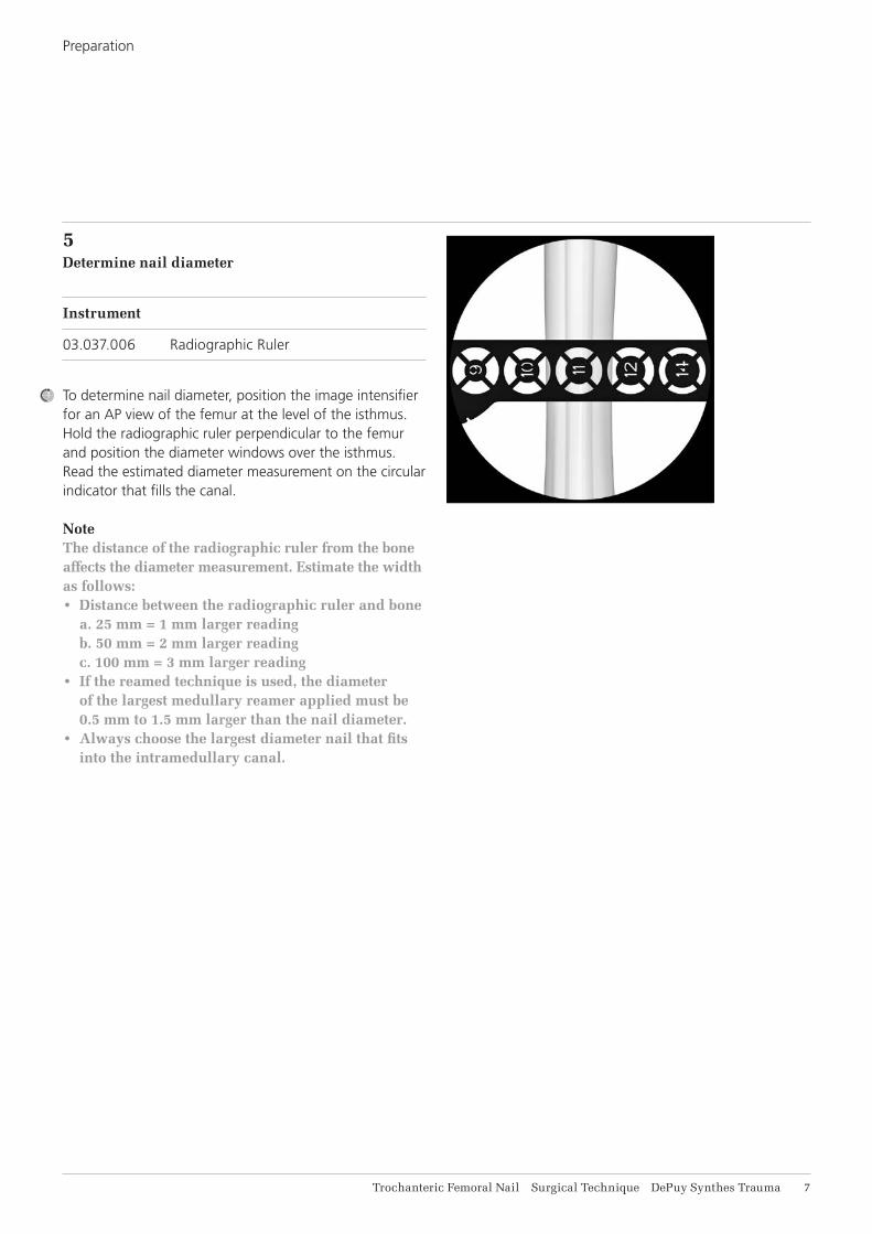
5Determine nail diameter
Instrument
03.037.006 Radiographic Ruler
To determine nail diameter, position the image intensifier for an AP view of the femur at the level of the isthmus. Hold the radiographic ruler perpendicular to the femur and position the diameter windows over the isthmus. Read the estimated diameter measurement on the circular indicator that fills the canal.
Note The distance of the radiographic ruler from the bone affects the diameter measurement. Estimate the width as follows:• Distance between the radiographic ruler and bone
a. 25 mm = 1 mm larger reading b. 50 mm = 2 mm larger reading c. 100 mm = 3 mm larger reading
• If the reamed technique is used, the diameter of the largest medullary reamer applied must be 0.5 mm to 1.5 mm larger than the nail diameter.
• Always choose the largest diameter nail that fits into the intramedullary canal.

8 DePuy Synthes Trauma Trochanteric Femoral Nail Surgical Technique
OPEN PROXIMAL FEMUR
1Identify nail entry point
Make a longitudinal incision proximal to the greater trochanter. Carry the dissection down to the gluteus medius fascia longitudinally in the direction of the wound. Separate the underlying muscle fibers and palpate the tip of the greater trochanter.
In the lateral view, the entry point for the nail is centered in the greater trochanter and in line with the medullary canal.
In the AP view, the nail insertion point is on the tip or slightly lateral to the tip of the greater trochanter, in the curved extension of the medullary cavity. This represents a point, 5° lateral of the femoral shaft axis, measured from a point just below the lesser trochanter, as the ML angle of the nail is 5°.

Trochanteric Femoral Nail Surgical Technique DePuy Synthes Trauma 9
2Insert guide wire
Instruments
03.037.000 Multihole Drill Sleeve
03.037.001 Protection Sleeve
357.399 Guide Wire B 3.2 mm, length 400 mm
393.100 Universal Chuck with T-Handle
Alternative instruments
03.037.100 Multihole Drill Sleeve, long
03.037.101 Protection Sleeve, long
09.037.010 Guide Wire B 3.2 mm, length 475 mm
393.100 Universal Chuck with T-Handle
Position the protection sleeve and the multi hole drill sleeve assembly at the insertion point.
Insert the guide wire through the drill sleeve. Confirm guide wire placement in both the AP and lateral planes. Insert to a depth of approximately 15 cm. Remove the drill sleeve.
If the first guide wire is inserted in an incorrect position, a second guide wire can be inserted through one of the additional holes in the multi hole drill sleeve at either 4 mm or 6 mm from the central hole. Once the guide wire is in the desired entry point, remove the first guide wire.
Open Proximal Femur

11 DePuy Synthes Trauma Trochanteric Femoral Nail Surgical Technique
Alternative technique
Instruments
03.037.008 Awl B 8/4.7 mm, curved, cannulated or 03.037.007 Awl B 8/4.7 mm, straight, cannulated
The entry point can also be determined by using the awl. After initial opening with the awl, insert the 950 mm reaming rod through the cannulation.
Open Proximal Femur

Trochanteric Femoral Nail Surgical Technique DePuy Synthes Trauma 11
3Open canal
Instruments
03.037.001 Protection Sleeve
03.037.002 Drill Bit B 16 mm, flexible, cannulated, for Quick Coupling for DHS/DCS or 03.037.003 Drill Bit B 16 mm, cannulated, for Quick Coupling for DHS/DCS
Alternative instruments
03.037.101 Protection Sleeve, long
03.037.102 Drill Bit B 16 mm, long, flexible, cannulated, for Quick Coupling for DHS/DCS or 03.037.103 Drill Bit B 16 mm, long, cannulated, for Quick Coupling for DHS/DCS
Guide the flexible cannulated drill bit over the guide wire through the protection sleeve to the bone and drill to the stop.
Remove and dispose of the guide wire. Do not reuse.
Open Proximal Femur
12 DePuy Synthes Trauma Trochanteric Femoral Nail Surgical Technique
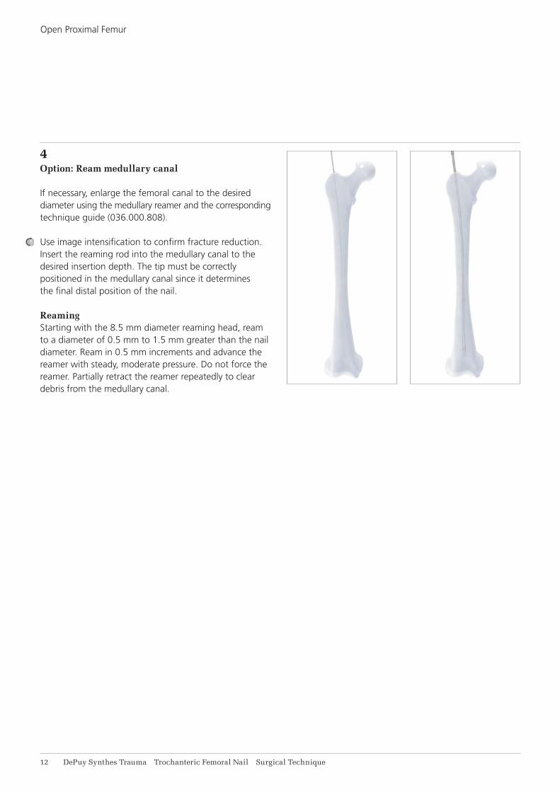
4Option: Ream medullary canal
If necessary, enlarge the femoral canal to the desired diameter using the medullary reamer and the corresponding technique guide (036.000.808).
Use image intensification to confirm fracture reduction. Insert the reaming rod into the medullary canal to the desired insertion depth. The tip must be correctly positioned in the medullary canal since it determines the final distal position of the nail.
ReamingStarting with the 8.5 mm diameter reaming head, ream to a diameter of 0.5 mm to 1.5 mm greater than the nail diameter. Ream in 0.5 mm increments and advance the reamer with steady, moderate pressure. Do not force the reamer. Partially retract the reamer repeatedly to clear debris from the medullary canal.
Open Proximal Femur
Trochanteric Femoral Nail Surgical Technique DePuy Synthes Trauma 13
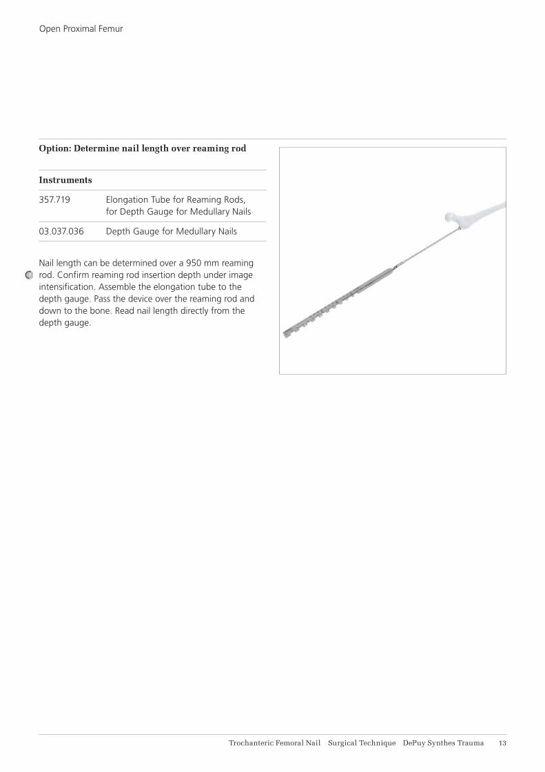
Option: Determine nail length over reaming rod
Instruments
357.719 Elongation Tube for Reaming Rods, for Depth Gauge for Medullary Nails
03.037.036 Depth Gauge for Medullary Nails
Nail length can be determined over a 950 mm reaming rod. Confirm reaming rod insertion depth under image intensification. Assemble the elongation tube to the depth gauge. Pass the device over the reaming rod and down to the bone. Read nail length directly from the depth gauge.
Open Proximal Femur

14 DePuy Synthes Trauma Trochanteric Femoral Nail Surgical Technique
1Assemble insertion instruments
Instruments
03.037.010 Connecting Screw for Insertion Handle
03.037.012 Insertion Handle or 03.037.011 Insertion Handle, hybrid or 03.037.112 Insertion Handle, long
03.010.517 Screwdriver, hexagonal B 8.0 mm, with T-Handle, with spherical head, length 322 mm
Assemble the hexagonal screwdriver with spherical head to the connecting screw until it clicks into the recess.
Match the geometry of the handle to the nail and connect the nail to the insertion handle. The nail will click-in and self-retain.
Pass the connecting screw through the insertion handle and securely tighten the screwdriver. Remove the hexagonal screwdriver.
Precaution• Ensure that the connection between the nail and
the insertion handle is tight (retighten if necessary).• Do not attach the aiming arm to the insertion
handle yet.• If a 235 mm or longer nail is selected, reconfirm
that the correct nail (right or left) is assembled.
INSERT NAIL

Trochanteric Femoral Nail Surgical Technique DePuy Synthes Trauma 15
2Insert nail
Instrument
03.037.012 Insertion Handle or 03.037.011 Insertion Handle, hybrid or 03.037.112 Insertion Handle, long
Short nails (170 mm, 200 mm and 235 mm)Orient the insertion handle laterally, taking into consideration the anteversion of the femoral head and neck. Manually insert the nail into the femoral opening. When using a reaming rod, pass the cannulated nail over the reaming rod and into the femoral opening.
Under image intensification, verify fracture reduction and insert the nail as far as possible by hand. Use the insertion assembly to manipulate the nail across the fracture.
When inserting a short nail (170 mm, 200 mm and 235 mm), no hammer blows should be required.
Long nails (260 mm to 480 mm)Orient the insertion handle anteriorly until the nail reaches the isthmus. Manually insert the nail into the femoral opening. When using a reaming rod, pass the cannulated nail over the reaming rod and into the femoral opening. As the nail is advanced, rotate the handle so it is positioned laterally for final seating.
Under image intensification, verify fracture reduction and insert the nail as far as possible by hand. Use the insertion assembly to manipulate the nail across the fracture. Insertion can be aided by light hammer blows on the driving cap, as described in the step below.
If a reaming rod has been used, it should be removed once the nail has crossed the fracture site.
Insert Nail
Short nails
Long nails

16 DePuy Synthes Trauma Trochanteric Femoral Nail Surgical Technique
Insert Nail
3Insert nail with hammer (optional)
Instruments
03.010.522 Combined Hammer, 500 g
03.010.523 Driving Cap with thread, for Insertion Handle
03.037.120 Connector for Driving Cap
03.037.031 Wrench, hexagonal 11.0/9.6 /8.6 mm
03.010.170 Hammer Guide
To use a hammer, insert the connector into the the insertion handle and screw the driving cap through the connector onto the insertion handle. Tighten with combination wrench. When using the hybrid insertion handle, the hammer guide connector is not used and the driving cap is inserted directly into the hybrid insertion handle.
While applying light blows, monitor the tip of the nail using image intensification. Verify that there is no evidence of impingement distally. Remove the driving cap and the connector once the nail has been seated.
Note: Using light blows, the hammer can also be used with the hammer guide to back slap the nail if the nail has been slightly over inserted.
Precaution: Confirm that the nail is tightly connected to the insertion handle, as hammering may loosen the connection.

Trochanteric Femoral Nail Surgical Technique DePuy Synthes Trauma 17
1Choose aiming arm
Instruments
Aiming Arms CCD: 125° 03.037.014 (static distal locking) 03.037.114 (static and dynamic distal locking)
130° 03.037.013 (static distal locking) 03.037.113 (static and dynamic distal locking)
135° 03.037.035 (static distal locking) 03.037.135 (static and dynamic distal locking)
Ensure that the nail is tightly connected to the insertion handle. Retighten if necessary.
Choose the aiming arm that matches the angle of the nail inserted and securely attach to the insertion handle by tightening the thumb screw.
PROXIMAL LOCKING
2Verify nail insertion depth
Instrument
357.399 Guide Wire B 3.2 mm, length 400 mm
Verify nail insertion depth and position for the helical blade /femoral neck screw. Place a guide wire on the yellow marking of the aiming arm and radiographically check the guide wire position in AP.

18 DePuy Synthes Trauma Trochanteric Femoral Nail Surgical Technique
Alternative technique: Position guide wire with guide wire aiming device
Instruments
03.010.412 Aiming Device for Guide Wire, for PFNA and TFN, for AP orientation
03.010.415 Connecting Screw for TFN, for 03.010.412
03.010.471 Guide Wire Aiming Device Offset Block, 100 mm
Insert the aiming device into the three holes on the aiming arm and attach it to the aiming arm using the connecting screw.
Option: The guide wire aiming device offset block can be added between the aiming arm and the guide wire aiming device to obtain an additional 10 cm of soft tissue clearance.
Position the C-arm for an AP image. Rotate the C-arm until any two dotted orientation lines are parallel to the proximal locking hole. The midline in between these two orientation lines represents the guide wire trajectory.
Note: The outer lines can be used to determine the center of the femoral head.
Proximal Locking

Trochanteric Femoral Nail Surgical Technique DePuy Synthes Trauma 19
3Verify nail anteversion
Instrument
357.399 Guide Wire B 3.2 mm, length 400 mm
Position the C-arm in the true lateral view (alignment of the axis of the femoral neck congruent with the axis of the femoral shaft).
Adjust nail rotation until the two lines on the insertion handle are parallel to the nail.
Option: A guide wire can be inserted in the corresponding hole in the insertion handle to predict the location of the guide wire and helical blade/femoral neck screw.
Proximal Locking

21 DePuy Synthes Trauma Trochanteric Femoral Nail Surgical Technique
4Insert guide sleeve
Instruments
03.037.016 Buttress/Compression Nut
03.037.017 Guide Sleeve, yellow
03.037.018 Drill Sleeve, yellow
03.037.019 Trocar, yellow
03.010.491 Handle for Scalpel, long
To make an incision to accommodate the path of the sleeve assembly, insert the handle with scalpel blade attached through the corresponding hole of the aiming arm. Ensure that the incision and dissection of the fascia is in line with the path of the sleeve assembly.
Thread the buttress/compression nut onto the blade/screw guide sleeve, to the black marking.
Assemble the yellow marked trocar and the drill sleeve into the guide sleeve. Place the assembly through the aiming arm and through the soft tissue to the bone. Slightly rotating the assembly while pushing through the soft tissue may help facilitate insertion. Advance the assembly until the buttress/compression nut clicks into the aiming arm.
Proximal Locking

Trochanteric Femoral Nail Surgical Technique DePuy Synthes Trauma 21
Turn the buttress/compression nut counterclockwise to advance the guide sleeve to the bone. Take an AP C-arm image to confirm that the tooth on the guide sleeve is just touching the lateral cortex.
Precaution: The distal tooth of the guide sleeve should rest on the lateral cortex. Do not over tighten on the cortex as this may affect the accuracy of the aiming assembly.
Using a light hammer blow, hit the trocar into the bone to create an indentation in the bone which will help prevent the guide wire from skiving off of the bone in the next step.
Reconfirm fracture reduction using image intensification.
Proximal Locking

10 mm
22 DePuy Synthes Trauma Trochanteric Femoral Nail Surgical Technique
Proximal Locking
5Insert guide wire for blade or screw
Instruments
03.037.019 Trocar, yellow
357.399 Guide Wire B 3.2 mm, length 400 mm
Remove the trocar and pass a new guide wire through the drill sleeve to the bone. Advance the guide wire into the femoral head, stopping approximately 10 mm below the joint level.
The guide wire should be centered in the femoral head and neck in both the AP and lateral planes. The tip of the guide wire is positioned where the tip of the head element will be when the head element is properly inserted.
Confirm guide wire placement, in both planes, using the image intensifier.
Precaution • If the nail must be repositioned to improve guide
wire placement, remove the guide sleeve assembly and adjust with the insertion handle. Make a new incision for insertion of the guide sleeve, if necessary. Do not pull on the guide sleeve or power tool to make this adjustment as this could affect the accuracy of the aiming.
• Do not reuse guide wires as they may bend during initial use. If the guide is deformed during insertion use a new guide and discard deformed guide wire.
Note: When inserting the guide wire in patients with larger anatomies, it might be necessary to stop during wire insertion and remove the drill sleeve. This is most likely to occur in anatomies requiring helical blade/femoral neck screw lengths of 120 mm or larger.

Trochanteric Femoral Nail Surgical Technique DePuy Synthes Trauma 23
Optional technique: Rotational control of femoral head
Instruments
357.399 Guide Wire B 3.2 mm, length 400 mm
357.413 Drill Sleeve 5.6/3.2, length 198 mm
In very unstable fractures, insert an additional guide wire to prevent rotation. After the guide wire has been inserted, pass the drill sleeve through the corresponding anterior or posterior hole on the aiming arm. Make a stab incision and pass the sleeve to the bone. Advance a guide wire into the femoral head. Monitor passage with the image intensifier.
Repeat to place a second guide wire if necessary.
The guide wires will converge towards the tip of the helical blade/femoral neck screw, but will not touch it. The guide wires should be used for provisional fixation only and removed once the helical blade/femoral neck screw has been inserted.
Proximal Locking

24 DePuy Synthes Trauma Trochanteric Femoral Nail Surgical Technique
6Measure helical blade/femoral neck screw length
Instrument
03.037.020 Direct Measuring Device, yellow
To measure the helical blade or femoral neck screw length, pass the measuring device over the guide wire to the back of the guide sleeve. The length is read directly from the measuring device. No calculations are required.
Note: The measurement is calibrated from the tip of the guide wire to the tip of the tooth on the guide sleeve.
Proximal Locking

Trochanteric Femoral Nail Surgical Technique DePuy Synthes Trauma 25
7Open lateral cortex for helical blade/femoral neck screw insertion
Instruments
03.037.017 Guide Sleeve, yellow
03.037.021 Drill Bit for lateral cortex opening, for Quick Coupling for DHS/DCS
Remove the drill sleeve. Pass the drill bit over the guide wire, through the guide sleeve, and drill to the stop. This will open the lateral cortex.
Note: If the guide wire deflected as it passed into the femoral head/neck, it may be removed before drilling and blade/screw insertion. If the guide wire falls out or comes out when the drill bit is removed, it may be left out for blade/screw insertion. Care should be taken to ensure the orientation of the insertion handle and aiming arm is not altered.
Proximal Locking

26 DePuy Synthes Trauma Trochanteric Femoral Nail Surgical Technique
Option: Drilling for dense bone or when using a femoral neck screw
Instruments
03.037.022 Stepped Reamer for Helical Blade and Femoral Neck Screw for Quick Coupling for DHS/DCS
03.037.023 Fixation Sleeve for Stepped Reamer
03.010.093 Rod Pusher for Reaming Rod with Hexagonal Screwdriver B 8.0 mm
For dense bone or when using a femoral neck screw, the stepped reamer should be used to prepare a path for the full length of the implant. The stepped reamer should be used only after the lateral cortex has been opened.
Pass the fixation sleeve over the back end of the stepped reamer and check the fixation sleeve for wear per the instructions on page 59. Adjust the setting to the measured implant length. Pass the reamer over the guide wire, through the guide sleeve and advance it the stop.
Use the rod pusher through to hold the guide wire in place while removing the stepped reamer.
Note• Clean the flutes if high resistance is felt.• Drill always stops 5 mm short of the wire tip.
Proximal Locking

Trochanteric Femoral Nail Surgical Technique DePuy Synthes Trauma 27
8aAssemble helical blade
Instruments
03.037.024 Helical-Blade Impactor
03.037.026 Connecting Screw for Helical Blade and Femoral Neck Screw
Insert the connecting screw and thread in until fully captured in the helical–blade impactor. The connecting screw will remain attached to the instrument. Select the appropriate length helical blade as measured. Align the back end of the helical blade with the impactor. Further thread the connecting screw into the helical blade and finger tighten the assembly.
Proximal Locking
OPTION A: HELICAL BLADE INSERTION

28 DePuy Synthes Trauma Trochanteric Femoral Nail Surgical Technique
9aInsert helical blade
Instrument
03.010.522 Combined Hammer, 500 g
Pass the helical-blade impactor assembly through the guide sleeve and align the red line on the impactor shaft with the red line on the guide sleeve. Advance the helical blade as far as possible by hand. Use light hammer blows on the back of the connecting screw until the impactor comes to a stop at the back of the guide sleeve. In the final position the yellow line on the guide sleeve is in alignment to the yellow line on the impactor.
The helical blade MUST be fully inserted.
Precaution• Image intensifier should be used during
blade insertion to monitor positioning.• Assure that the guide wire is in place while
inserting the helical blade to prevent the cannulation from clogging, impeding an optional augmentation procedure.
Option: To intraoperatively exchange the blade, attach the Driving Cap 03.010.523 to the back of the coupling screw. Use the hammer to back slap if needed.
Proximal LockingOption A: Helical Blade Insertion

Trochanteric Femoral Nail Surgical Technique DePuy Synthes Trauma 29
8bTap for femoral neck screw (optional)
Instrument
03.037.027 Tap for Femoral Neck Screw
The tap may be used to prepare a pathway for the femoral neck screw.
Note: Only use the tap in dense bone.
Pass the tap over the guide wire, through the guide sleeve and through the nail. Advance the tap manually by turning clockwise until the tip of the tap reaches the desired screw placement in the femoral head.
Precaution: There is no stop on the tap so monitoring insertion via the following methods is recommended:• Monitor the depth under fluoroscopy• Monitor the respective graduations of the instrument
shaft in relation to the guide sleeve
Remove the tap by turning counterclockwise.
Proximal Locking
OPTION B: FEMORAL NECK SCREW INSERTION
9bAssemble femoral neck screw
Instruments
03.037.025 Femoral Neck Screw Inserter
03.037.026 Connecting Screw for Helical Blade and Femoral Neck Screw
Insert the connecting screw and thread in until fully captured in the screw inserter. The connecting screw will remain attached to the inserter. Select the appropriate length femoral neck screw as measured. Align the back end of the femoral neck screw with the inserter. Further thread the connecting screw into the femoral neck screw and finger tighten the assembly.

31 DePuy Synthes Trauma Trochanteric Femoral Nail Surgical Technique
10bInsert screw
Starting notes• The femoral neck screw advances 1.75 mm
increments by turning the handle 180° (or 3.5 mm by turning 360°).
• When adjusting for final positioning, always rotate the handle clockwise, further engaging the screw in the bone. Do not rotate counterclockwise, as this will leave a gap between the screw and the bone.
• The screw can be over inserted a maximum of 1 (one) full turn.
• The etched image on the inserter indicates the orientation of the lateral oblique end of the femoral neck screw.
Pass the screw insertion assembly over the guide wire, through the guide sleeve and through the nail. Advance the screw by turning the inserter clockwise until the line on the inserter meets the flange surface of the guide sleeve. At this depth the screw tip will be positioned at the tip of the guide wire. Assure that the inserter handle is aligned to the aiming arm. This is essential for proper engagement of the locking mechanism.
Precaution • Image intensifier should be used during screw
insertion to monitor positioning. • Assure that the guide wire is in place while
inserting the helical blade to prevent the cannulation from clogging, impeding an optional augmentation procedure.
Proximal Locking
Trochanteric Femoral Nail Surgical Technique DePuy Synthes Trauma 31
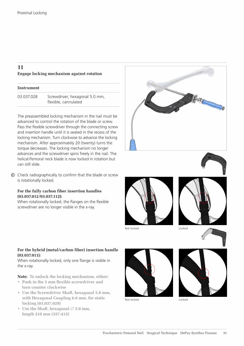
11Engage locking mechanism against rotation
Instrument
03.037.028 Screwdriver, hexagonal 5.0 mm, flexible, cannulated
The preassembled locking mechanism in the nail must be advanced to control the rotation of the blade or screw. Pass the flexible screwdriver through the connecting screw and insertion handle until it is seated in the recess of the locking mechanism. Turn clockwise to advance the locking mechanism. After approximately 20 (twenty) turns the torque decreases. The locking mechanism no longer advances and the screwdriver spins freely in the nail. The helical /femoral neck blade is now locked in rotation but can still slide.
Check radiographically to confirm that the blade or screw is rotationally locked.
For the fully carbon fiber insertion handles (03.037.012/03.037.112):When rotationally locked, the flanges on the flexible screwdriver are no longer visible in the x-ray.
For the hybrid (metal/carbon fiber) insertion handle (03.037.011): When rotationally locked, only one flange is visible in the x-ray.
Note: To unlock the locking mechanism, either:• Push in the 5 mm flexible screwdriver and
turn counter clockwise • Use the Screwdriver Shaft, hexagonal 5.0 mm,
with Hexagonal Coupling 6.0 mm, for static locking (03.037.029)
• Use the Shaft, hexagonal B 5.0 mm, length 210 mm (357.415)
Proximal Locking
Not locked Locked
Not locked Locked

32 DePuy Synthes Trauma Trochanteric Femoral Nail Surgical Technique
Option A: Helical blade compression
Instrument
321.170 Pin Wrench B 4.5 mm, length 120 mm
Once the helical blade has been locked in rotation, interfragmentary compression can be obtained by turning the buttress/compression nut clockwise by hand. For additional leverage, use the pin wrench.
Precaution: Caution should be taken when using the buttress/compression nut with the pin wrench to avoid over compression which could potentially cause the helical blade to lose purchase in the bone, especially in patients with poor bone quality.
Proximal Locking
OPTION: INTERFRAGMENTARY COMPRESSION
Option B: Femoral neck screw compression
Instruments
03.037.116 Compression Nut for Screw Inserter
321.170 Pin Wrench B 4.5 mm, length 120 mm
Once the femoral neck screw screw has been locked in rotation, interfragmentary compression can be obtained by mounting the compression nut onto the screw inserter. Turn it until it abuts the guide sleeve. Turn the buttress/compression nut clockwise by hand. For additional leverage, use the pin wrench.
Precaution: Caution should be taken when using the buttress/compression nut with the pin wrench to avoid over compression which could potentially cause the femoral neck screw to lose purchase in the bone, especially in patients with poor bone quality.

Trochanteric Femoral Nail Surgical Technique DePuy Synthes Trauma 33
Option: Engage locking mechanism against sliding (static locking)
Instruments
03.037.029 Screwdriver Shaft, hexagonal 5.0 mm, with Hexagonal Coupling 6.0 mm, for static locking
03.140.023* Torque Limiter, 6 Nm, for AO/ASIF Quick Coupling for Reamer
03.010.496 T-Handle, cannulated, with Quick Coupling, Hex 12 mm
The helical blade or femoral neck screw can be statically locked against sliding.
Assemble the torque limiter to the T-Handle and to the hexagonal screwdriver shaft.
Pass the static locking screwdriver assembly through the connecting screw and insertion handle until it is seated in the hexagonal recess of the locking mechanism. Turn clockwise to further advance. Turn until the torque limiter releases. After one click, the optimal torque is reached and the helical blade or femoral neck screw is statically locked.
Note: The torque limiter ensures that the correct torque is achieved to engage the locking mechanism against sliding.
Proximal LockingOption: Interfragmentary Compression
* Recalibration of the torque limiter: DePuy Synthes recommends annual servicing and inspection by the original manufacturer. The torque limiter has to be sent to your DePuy Synthes repair center annually for calibration. The user accepts the responsibility for this annual calibration.

34 DePuy Synthes Trauma Trochanteric Femoral Nail Surgical Technique
Proximal Locking
12Remove proximal locking instruments
Disconnect the connecting screw from the helical blade or femoral neck screw. If the connecting screw cannot be loosened by hand, use the flexible screwdriver or pin wrench to loosen the connection.
If no augmentation is planned, remove the guide sleeve/inserter assembly from the aiming arm by pushing the locking device on the aiming arm and pulling out the complete guide sleeve assembly. Remove guide wire.
If augmentation is planned, remove the helical blade impactor and leave the guide sleeve in place to facilitate augmentation (see page 35ff).

1 21
Trochanteric Femoral Nail Surgical Technique DePuy Synthes Trauma 35
1Adjust sleeve of side-opening cannula
Instrument
03.702.121S Trauma Needle Kit, B 3.3 mm, Cannula with side-opening, sterile
Adjust the sleeve of the side-opening cannula to the selected head element length. Length adjustments are made by turning the side-opening cannula (1), while holding the sleeve (2).
General notes• It is recommended to use 3 ml of cement for augmen-
tation. This amount of cement minimizes the risk of avascular necrosis and is sufficient to achieve the desired stability. The injected amount must not exceed 6 ml of cement.
• Aimed placement of cement is around the helical part of the blade/screw. The PMMA cement filling should have a distance of 6 mm–10 mm to the joint surface. Filling of the cavity lateral to the helical part of the blade/screw is not necessary.
• The working time for Traumacem V+ at room temperature (20°C) is approximately 27 minutes. At body temperature (37°C) the setting time is 15 minutes. Mobilizing/Repositioning the patient before 15 minutes after the last injection should therefore be avoided.
AUGMENTATION

36 DePuy Synthes Trauma Trochanteric Femoral Nail Surgical Technique
2Check for possible cement leakage into joint
Instrument
03.702.121S Trauma Needle Kit, B 3.3 mm, Cannula with side-opening, sterile
Other materials
1– 2 Syringes (6–10 ml) with Luer lock
Radiographic contrast agent
Saline solution
Attach the syringe with luer lock to the side-opening cannula and pre-fill the side-opening cannula with approximately 4 ml of radiographic contrast agent.
Insert the side-opening cannula through the guide sleeve into the helical blade/femoral neck screw until the stop.
Confirm that the selected length on the side-opening cannula corresponds with the length of the helical blade/femoral neck screw and verify under image intensification that the side opening cannula is fully inserted. At the correct position the tip of the sleeve has disappeared in the lateral end of the helical blade/femoral neck screw. Monitor the correct position of the sleeve throughout the procedure.
Augmentation
Correct – tip has disappeared in the screw/blade.
Wrong – tip of the sleeve visible.

Trochanteric Femoral Nail Surgical Technique DePuy Synthes Trauma 37
Augmentation
Leakage into joint. Do not augment.No leakage into joint.
Inject radiographic contrast agent into the femoral head and monitor the flow under image intensification.
Remove the side-opening cannula.
Wash the radiographic contrast agent out of the cannula and, if necessary, out of the femoral head using a saline solution and another syringe (6–10 ml), attached to the side-opening cannula.
Precaution • Do not augment if radiographic contrast agent leaks
into the joint and proceed with distal locking.• Use only radiographic contrast agents that are
indicated for this application.• Consult the manufacturer’s directions on indications,
contraindications, use, precautions, warnings and side effects of the radiographic contrast agent.

1
2
3
4
38 DePuy Synthes Trauma Trochanteric Femoral Nail Surgical Technique
Augmentation
3Prepare cement
Instrument
07.702.040S Traumacem V+ Cement Kit, 10 ml, sterile
Hold the Traumacem V+ Cement Kit upright and gently slat with the finger tip at the top of the mixing device in order to ensure no cement powder sticks to the cartridge and sterilization lid.
Pull the handle until it is fully retracted.
Note: Make sure to always handle the mixing device by gripping the blue part located directly below the transparent cartridge. If the transparent part is used as gripping surface, the excess body heat provided by the users hand might result in a shorter working time than intended.
Open the glass ampoule by breaking the bottle neck with the plastic cap (1). Remove and dispose the mixing device sterilization lid. Pour all monomer from the glass ampoule into the cement powder (2) and close the mixing device tightly using the enclosed transferring lid.
Note• Entire contents must always be mixed.• See also the quick step preparation technique
on the inner packaging of the Traumacem V+ Cement Kit.
Mix the Traumacem V+ Cement by moving the blue handle back and forth from stop to stop approximately 20 times (3). Perform the first mixing strokes slowly with oscillating-rotating movements. After mixing fully retract the handle.
Pull the handle until it is fully retracted (4).
Note: Ensure homogeneous mixing.

1
2 3
Trochanteric Femoral Nail Surgical Technique DePuy Synthes Trauma 39
Augmentation
4Fill injection syringes
Instrument
03.702.150S Trauma Syringe Kit, 4 x 1 ml, 2 x 2 ml, sterile
Once the cement has been mixed using the Traumacem V+ Cement Kit, remove the small, transparent mixer lid (1). Connect the stop-cock (the side without the funnel) to the mixer. Ensure a tight fit between the mixer and the stop-cock (2).
Note: The application of excessive torque will break the stop-cock.
First remove the air from the system. With the valve open, gently turn the handle of the cement mixer clockwise. The mixer piston will advance in the translucent cartridge and a steady flow of cement will move into the stop-cock. As soon as the cement is visible in the stop-cock, close the valve (3).
Note: Do not push to transfer cement.
Open Close

41 DePuy Synthes Trauma Trochanteric Femoral Nail Surgical Technique
Augmentation
Attach a 2 ml (white) syringe to the one way stop-cock (funnel side).
Open the one way stop-cock (the “off” sign facing away from the syringe).
Gently turn the handle of the cement mixer clockwise to advance the piston. As soon as the syringe is filled, close the stop-cock again, by turning the “off” sign towards the mixer.
Disconnect the full syringe and attach the next syringe to be filled. Avoid spillage of cement into the funnel during the transfer process and remove excess cement to avoid accidental pollution of the protection sleeve, blade or screw. Continue to fill all the 1 ml (blue) and 2 ml (white) syringes in the same manner. Always fill all syringes.

Trochanteric Femoral Nail Surgical Technique DePuy Synthes Trauma 41
5Pre-fill the side-opening cannula with Traumacem V+
Instrument
03.702.121S Trauma Needle Kit, B 3.3 mm, Cannula with side-opening, sterile
Attach a cement filled 2 ml syringe to the side-opening cannula. Pre-fill the side-opening cannula with the 2 ml of cement from the syringe. Attach another filled 2 ml syringe and fill the side-opening cannula until the cement is coming out of the side-opening, representing 4 ml of cement filled into the canal. Remove and discard the syringes. Attach a filled 1 ml syringe to the side-opening cannula in preparation of the augmentation.
In case of cement leakage from the side opening, remove the excess cement in order to avoid accidental pollution of the protection sleeve or blade/screw.
Note: 1 ml syringes must be used to inject cement. The 2 ml syringes are not suited to augment the blade/screw.
Augmentation

42 DePuy Synthes Trauma Trochanteric Femoral Nail Surgical Technique
6Insert side-opening cannula
Confirm that the selected length on the side-opening cannula corresponds with the length of the helical blade/femoral neck screw.
Insert the side-opening cannula through the guide sleeve into the blade/screw until the stop.
Verify under image intensification that the side opening cannula is fully inserted.
7Augmentation with Traumacem V+
Instrument
03.702.121S Trauma Needle Kit, B 3.3 mm, Cannula with side-opening, sterile
Injection of cement into the femoral head is performed using 1 ml syringes.
Slowly inject Traumacem V+ using 1 ml syringes. Optimize the filling by rotating the handle to inject cement around the blade/screw and more medially or laterally. A full turn of the sleeve corresponds to an adjustment of 5 mm.
Augmentation

Trochanteric Femoral Nail Surgical Technique DePuy Synthes Trauma 43
Visualization of cement during injection must be guaranteed. Continuously monitor the cement flow under image intensification.
Precaution • Do not advance the cannula more than 5 mm
over the selected head element length. This would result in injection of cement in front of the head element tip where no additional stability is achieved and the risk of penetration and cement leakage is increased.
• In the event that there is danger of cement leakage into the joint, fracture gap or venous system, stop injection immediately.
Note: The arrow on the handle indicates the position of the side-opening window of the cannula.
Option • Injection of cement can be continued using the
plunger when the viscosity is increasing or the cement in the cavity of the side-opening cannula is necessary for augmentation. Approximately 3 ml of cement contained in the side-opening cannula can be injected with the plunger.
• Remove the 1 ml syringe and insert the plunger. Continue the injection using the plunger and optimize the filling by rotating the handle.
Augmentation

44 DePuy Synthes Trauma Trochanteric Femoral Nail Surgical Technique
8
Remove the side-opening cannula
Push the locking device on the aiming arm to remove the side opening cannula/guide sleeve assembly. Remove the side-opening cannula as soon as the injection is complete and the cement is still malleable.
Augmentation
Trochanteric Femoral Nail Surgical Technique DePuy Synthes Trauma 45
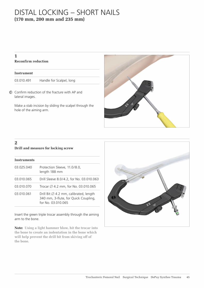
1Reconfirm reduction
Instrument
03.010.491 Handle for Scalpel, long
Confirm reduction of the fracture with AP and lateral images.
Make a stab incision by sliding the scalpel through the hole of the aiming arm.
2 Drill and measure for locking screw
Instruments
03.025.040 Protection Sleeve, 11.0/8.0, length 188 mm
03.010.065 Drill Sleeve 8.0/4.2, for No. 03.010.063
03.010.070 Trocar B 4.2 mm, for No. 03.010.065
03.010.061 Drill Bit B 4.2 mm, calibrated, length 340 mm, 3-flute, for Quick Coupling, for No. 03.010.065
Insert the green triple trocar assembly through the aiming arm to the bone.
Note: Using a light hammer blow, hit the trocar into the bone to create an indentation in the bone which will help prevent the drill bit from skiving off of the bone.
DISTAL LOCKING – SHORT NAILS (170 mm, 200 mm and 235 mm)
46 DePuy Synthes Trauma Trochanteric Femoral Nail Surgical Technique
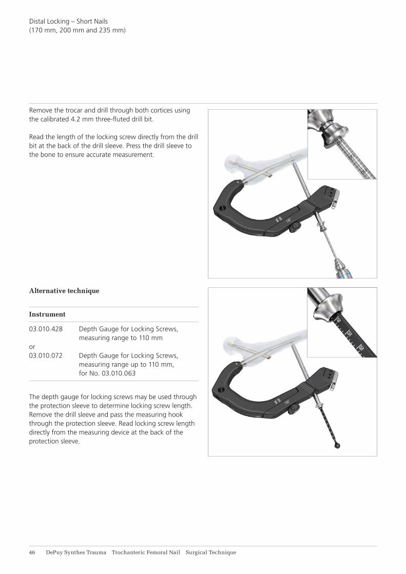
Remove the trocar and drill through both cortices using the calibrated 4.2 mm three-fluted drill bit.
Read the length of the locking screw directly from the drill bit at the back of the drill sleeve. Press the drill sleeve to the bone to ensure accurate measurement.
Distal Locking – Short Nails (170 mm, 200 mm and 235 mm)
Alternative technique
Instrument
03.010.428 Depth Gauge for Locking Screws, measuring range to 110 mm or 03.010.072 Depth Gauge for Locking Screws, measuring range up to 110 mm, for No. 03.010.063
The depth gauge for locking screws may be used through the protection sleeve to determine locking screw length. Remove the drill sleeve and pass the measuring hook through the protection sleeve. Read locking screw length directly from the measuring device at the back of the protection sleeve.

Trochanteric Femoral Nail Surgical Technique DePuy Synthes Trauma 47
3Insert locking screw
Instruments
03.010.518 Screwdriver STARDRIVE®, T25, self-holding, length 320 mm
03.025.040 Protection Sleeve 11.0/8.0, length 188 mm
Insert the appropriate 5.0 mm locking screw through the protection sleeve using the appropriate STARDRIVE screwdriver.
Remove the protection sleeve and aiming arm.
Distal Locking – Short Nails (170 mm, 200 mm and 235 mm)

48 DePuy Synthes Trauma Trochanteric Femoral Nail Surgical Technique
1Distal Locking
Distal locking of the long nail is performed with the freehand technique. Alternatively distal locking can be performed using the SURELOCKTM System and the corresponding technique guide (036.000.778).
Note: The SURELOCK System will only target the two most proximal distal locking holes in the long nail and only works with the Trochanteric Femoral Nails 280 mm to 460 mm in length.
There are three distal locking options:• Two transverse, lateral to medial holes – One of the holes is static and the other allows for
static or dynamic locking options• One oblique locking hole for enhanced stability in
trochanteric fractures with a shaft fracture. This is the most distal hole.
FREEHAND DISTAL LOCKING – LONG NAILS

Trochanteric Femoral Nail Surgical Technique DePuy Synthes Trauma 49
2Align image
Confirm reduction of the fracture with AP and lateral images.
Align the image intensifier with the hole in the nail until a perfect circle is visible in the center of the screen.
3Determine incision point
Place a scalpel blade on the skin over the center of the hole to mark the incision point and make a stab incision.
Freehand Distal Locking – Long Nails
Not aligned Aligned

51 DePuy Synthes Trauma Trochanteric Femoral Nail Surgical Technique
4Drill
Instrument
03.010.101 Drill Bit B 4.2 mm, calibrated, length
145 mm, 3-flute, with Coupling for RDL
Insert the drill into the radiolucent drive and insert it, through the incision, down to the bone.
Incline the drive so that the tip of the drill bit is centered over the locking hole. The drill bit should almost completely fill the circle of the locking hole. Hold the drill bit in this position and drill through both cortices.
Stop drilling immediately after both cortices and disassemble the drill bit from the power equipment.
Note: For greater drill bit control, discontinue drill bit power after perforating the near cortex. Manually guide the drill bit through the nail before resuming power to drill the far cortex.
Alternative instrument
03.010.104 Drill Bit B 4.2 mm, calibrated, length 145 mm, 3-flute, for Quick Coupling
Note: Before inserting the drill bit in the power tool, determine the right drilling position and fix the posi-tion with a light hammer tap on the back of the drill bit.
Stop drilling immediately after both cortices and disassemble the drill bit from the power equipment.
Freehand Distal Locking – Long Nails
Trochanteric Femoral Nail Surgical Technique DePuy Synthes Trauma 51
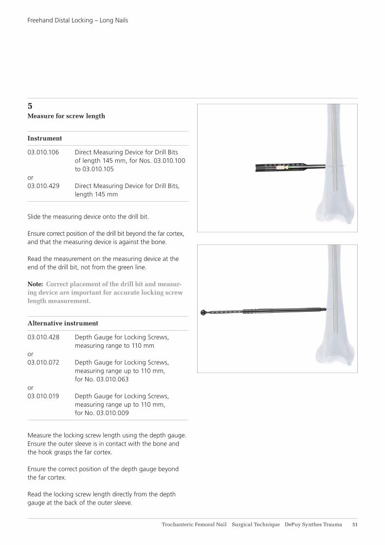
5Measure for screw length
Instrument
03.010.106 Direct Measuring Device for Drill Bits of length 145 mm, for Nos. 03.010.100 to 03.010.105 or 03.010.429 Direct Measuring Device for Drill Bits, length 145 mm
Slide the measuring device onto the drill bit.
Ensure correct position of the drill bit beyond the far cortex, and that the measuring device is against the bone.
Read the measurement on the measuring device at the end of the drill bit, not from the green line.
Note: Correct placement of the drill bit and measur-ing device are important for accurate locking screw length measurement.
Alternative instrument
03.010.428 Depth Gauge for Locking Screws, measuring range to 110 mm or 03.010.072 Depth Gauge for Locking Screws, measuring range up to 110 mm, for No. 03.010.063 or 03.010.019 Depth Gauge for Locking Screws, measuring range up to 110 mm, for No. 03.010.009
Measure the locking screw length using the depth gauge. Ensure the outer sleeve is in contact with the bone and the hook grasps the far cortex.
Ensure the correct position of the depth gauge beyond the far cortex.
Read the locking screw length directly from the depth gauge at the back of the outer sleeve.
Freehand Distal Locking – Long Nails

52 DePuy Synthes Trauma Trochanteric Femoral Nail Surgical Technique
6Insert locking screw
Instruments
03.010.518 Screwdriver STARDRIVE, T25, self-holding, length 320 mm
03.010.473 Inter-Lock Screwdriver, combined, STARDRIVE, T25/hexagonal B 3.5, length 224 mm
Insert the appropriate length screw using the screwdriver.
Verify locking screw length under image intensification.
Repeat steps 2 to 6 for the second and third proximal locking screw if the fracture necessitates additional distal fixation.
Freehand Distal Locking – Long Nails

Trochanteric Femoral Nail Surgical Technique DePuy Synthes Trauma 53
1Insert end cap
Instruments
03.010.517 Screwdriver, hexagonal B 8.0 mm, with T-Handle, with spherical head, length 322 mm
03.010.520 Screwdriver STARDRIVE, T40, with spherical head, cannulated, length 277 mm
357.399 Guide Wire B 3.2 mm, length 400 mm
Use of an end cap is recommended if bony ingrowth into the proximal end of the nail is of concern. Also, in reverse oblique intertrochanteric and high subtrochanteric fractures, the nail should be slightly proud of the greater trochanter to provide an added point of fixation. If the nail has been over inserted, it should be extended by the use of an end cap of appropriate length.
Note: The insertion depth of the nail is indicated by the rings on the insertion handle. Starting distally, each ring is an additional 5 mm from the tip of the nail. This will help in end cap selection.
Inserting the 0 mm end cap
Remove the connecting screw using the ball hexagonal screwdriver with spherical head while leaving the insertion handle connected to the nail.
Insert the 0 mm end cap using the STARDRIVE screwdriver through the insertion handle. A guide wire can be used to help ensure alignment while inserting the end cap.
After the end cap is inserted, remove the insertion handle from the nail.
Inserting the 5–15 mm end cap
Remove the connecting screw and insertion handle using the hexagonal screwdriver with spherical head.
Insert the end cap using the STARDRIVE screwdriver. A guide wire can be used to help ensure alignment while inserting the end cap.
INSERT END CAP
Inserting the 0 mm end cap.
Inserting the 5–15 mm end cap.

54 DePuy Synthes Trauma Trochanteric Femoral Nail Surgical Technique
1Disengage locking mechanism
Instruments
03.037.028 Screwdriver, hexagonal 5.0 mm, flexible, cannulated
03.037.030 Extraction Instrument for Helical Blade and Femoral Neck Screw
03.037.032 Extraction Instrument for Nails, cannulated
03.010.520 Screwdriver STARDRIVE, T40, with spherical head, cannulated, length 277 mm
356.717 Guide Wire B 2.8 mm, 460 mm length, with hook
356.715 Socket, hexagonal, B 11.0/§11.0 mm
Use the STARDRIVE screwdriver to remove the end cap, optionally assisted by use of the guide wire with hook.
Option: For removal of 5 mm, 10 mm and 15 mm end caps, the hexagonal socket 11.0 mm (356.715) also be used.
Thread the extraction instrument for helical blade/femoral screw into the implant by turning counterclockwise. Do not yet extract the helical blade/femoral neck screw.
Note: Check the recess in the helical blade or femoral neck screw before attaching the extraction instrument. In case of ingrown tissue or blockage with cement clean the recess with a sharp hook.
Thread the extraction instrument for blade and screw into the top of the nail. Pass the hexagonal flexible screwdriver through the instrument and engage the hex in the locking mechanism. Turn counterclockwise to disengage the the locking mechanism.
Note: It may be easier to align the nail extractor if the flexible screwdriver is passed through the nail extractor first and then both instruments engage in the top of the nail.
IMPLANT REMOVAL
Precaution: Do not attempt to remove the nail at this point.
Do not yet extract the screw/blade.
Do not yet extract the nail.

Trochanteric Femoral Nail Surgical Technique DePuy Synthes Trauma 55
Implant Removal
2Remove helical blade or femoral neck screw and distal locking screw
Instruments
03.037.030 Extraction Instrument for Helical Blade and Femoral Neck Screw
03.010.522 Combined Hammer, 500 g
03.010.518 Screwdriver STARDRIVE, T25, self-holding, length 320 mm
03.010.170 Hammer Guide
Remove the distal locking screws using the STARDRIVE screwdriver.
For the helical blade removal, slide the hammer over the helical blade/screw extractor and use light hammer blows, hammer until the helical blade is removed from the bone.
Note: The hammer guide may be threaded in the back of the helical blade/femoral neck screw extractor to extend the working length and thus support the removal.
For the femoral neck screw screw, continue to turn counterclockwise with a slight pulling force until the screw is removed from the bone.
Remove helical blade or femoral neck screw from the extractor
Instrument
03.037.031 Wrench, hexagonal 11.0/9.6/8.6 mm
The end of the combination wrench marked “BLADE/SCREW” can be attached to the helical blade or femoral neck screw and then used to disengage the helical blade or femoral neck screw from the extraction instrument. Rotate clockwise as the helical blade and femoral neck screw have a left handed thread for removal.

56 DePuy Synthes Trauma Trochanteric Femoral Nail Surgical Technique
3Extract nail
Instruments
03.010.170 Hammer Guide
03.010.522 Combined Hammer, 500 g
To remove the nail, thread the hammer guide onto the back end of the nail extraction instrument. Attach the combined hammer to the hammer guide and then use light hammer blows to extract the nail.
After the nail has been extracted from the bone, dissemble the extractor from the nail.
Implant Removal

Trochanteric Femoral Nail Surgical Technique DePuy Synthes Trauma 57
Implant Removal
ALTERNATIVE TECHNIQUE: EXTRACTION HOOKfor removal of broken nail
Instruments
355.399 Extraction Hook B 3.7 mm, for Cannulated Nails
393.100 Universal Chuck with T-Handle
Begin with Steps 1 and 2 of Implant Removal.
Option 1
1Assemble extraction hook and universal chuckInsert the extraction hook into the universal chuck withT-Handle. The hook should be parallel with the T-Handle.This facilitates visualization of the hook position in the bone.
2Insert extraction hook through nailRemove the nails extraction instrument and pass the extraction hook through the cannula of the nail, including the distant fragment.
Note: Under image intensification, verify that the hook has passed through and engaged the distant end of the nail.
3Extract nailExtract both nail fragments.
Note: Keep the patient’s limb restrained to increase the efficiency of the extraction force.

58 DePuy Synthes Trauma Trochanteric Femoral Nail Surgical Technique
Implant RemovalAlternative Technique: Extraction Hookfor removal of broken nail
Option 2
1Remove near nail fragmentRemove the near nail fragment using the technique described in step 3 of the implant removal.
Note: The extraction hook can be used as an alternative to extraction instrumentation.
2Ream canalReam the medullary canal 1 mm larger than the nail diameter to clear a path for the distant nail fragment.
3Align extraction hookInsert the extraction hook and explanted near nail fragment into the medullary canal. The near nail fragment aligns the extraction hook with the cannulation of the distant nail fragment.
4Engage distant fragmentPass the extraction hook through the cannula of the distant nail fragment.
Note: Under image intensification, verify that the hook has passed through and engaged the distant end of the nail.
5Extract nailExtract both nail fragments.
Note: Keep the patient’s limb restrained to increase the efficiency of the extraction force.

Trochanteric Femoral Nail Surgical Technique DePuy Synthes Trauma 59
Instruments
03.037.022 Stepped Reamer for Helical Blade and Femoral Neck Screw for Quick Coupling for DHS/DCS
03.037.023 Fixation Sleeve for Stepped Reamer
Possible damageIf excessive wear occurs, the fixation sleeve can slip, resulting in incorrect drilling depth.
Before use:• Slide the fixation sleeve onto the drill bit.• Press on the fixation sleeve with the thumb without
pressing the button. If the fixation sleeve moves under pressure, replace it.
• Do the same test in the opposite direction. If the fixation sleeve moves, replace it.
Recommendation:• Drill only under periodic image intensifier control.• While drilling, do not force.• Replace fixation sleeves that do not pass the described
wear test.
CHECKING FIXATION SLEEVE WEAR

61 DePuy Synthes Trauma Trochanteric Femoral Nail Surgical Technique
IMPLANTS
Nails
Material• Ti-15Mo (TiMo)• Color: green
Locking Mechanism• Ti-6Al-7NB (TAN)• 40Co-20Cr-16Fe-15Ni-7Mo• Color: green
LengthsShort nails:
• 170 mm• 200 mm• 235 mm left/235 mm right
Long nails:
• 260 mm–480 mm (left and right nails, 20 mm increments)
DiametersDistal:
• Short nails: B 9/B 10/B 11/B 12• Long nails: B 9/B 10/B 11/B 12 /B 14
CCD Angle• 125°/130°/135°
Trochanteric Femoral Nail Surgical Technique DePuy Synthes Trauma 61
Implants
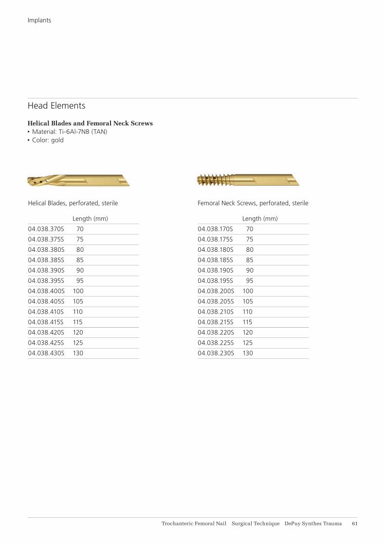
Head Elements
Helical Blades and Femoral Neck Screws• Material: Ti-6Al-7NB (TAN)• Color: gold
Femoral Neck Screws, perforated, sterile Length (mm)
04.038.170S 70
04.038.175S 75
04.038.180S 80
04.038.185S 85
04.038.190S 90
04.038.195S 95
04.038.200S 100
04.038.205S 105
04.038.210S 110
04.038.215S 115
04.038.220S 120
04.038.225S 125
04.038.230S 130
Helical Blades, perforated, sterile Length (mm)
04.038.370S 70
04.038.375S 75
04.038.380S 80
04.038.385S 85
04.038.390S 90
04.038.395S 95
04.038.400S 100
04.038.405S 105
04.038.410S 110
04.038.415S 115
04.038.420S 120
04.038.425S 125
04.038.430S 130

0 mm 5 mm 10 mm 15 mm
62 DePuy Synthes Trauma Trochanteric Femoral Nail Surgical Technique
Locking Screws*, B 5 mm Length Length (mm) (mm)
04.005.516 26 04.005.548 58
04.005.518 28 04.005.550 60
04.005.520 30 04.005.552 62
04.005.522 32 04.005.554 64
04.005.524 34 04.005.556 66
04.005.526 36 04.005.558 68
04.005.528 38 04.005.560 70
04.005.530 40 04.005.562 72
04.005.532 42 04.005.564 74
04.005.534 44 04.005.566 76
04.005.536 46 04.005.568 78
04.005.538 48 04.005.570 80
04.005.540 50 04.005.575 85
04.005.542 52 04.005.580 90
04.005.544 54 04.005.585 95
04.005.546 56 04.005.590 100
End Caps, sterile
Extension (mm)
0 04.038.000S
5 04.038.005S
10 04.038.010S
End Caps
MaterialTi-6Al-7NB (TAN)Color: green
Lengths 0 mm (sits fl ush with nail end)5 mm, 10 mm and 15 mm extensions
DesignRecess: STARDRIVE T40, Hexagonal 5.0 mm
* Available non-sterile or sterile packed. Add “S” to the article number toorder sterile products.
Locking Screws
MaterialTi-6Al-7NB (TAN)Color: light green
Drill4.2 mm diameter
Lengths 26 mm–80 mm (2 mm increments)80 mm–100 mm (5 mm increments)
DesignRecess: STARDRIVE T25
Implants

Trochanteric Femoral Nail Surgical Technique DePuy Synthes Trauma 63
IMPLANTS AND INSTRUMENTS FOR AUGMENTATION
07.702.040S Traumacem V+ Cement Kit, 10 ml, sterile
Containing:
1x Traumacem V+ mixer with sterilization lid
1 x Monomer glass ampoule
1 x Cement mixing and transferring lid
03.702.150S Trauma Syringe Kit, 4 x 1 mL,
2 x 2 mL, sterile
Containing:
4 x Blue 1 ml syringes
2 x White 2 ml syringes
1 x One-way stop-cock
03.702.121S Trauma Needle Kit B 3.3 mm, Cannula
with side-opening, sterile
Containing:
1 x Side-opening cannula, with Luer-lock
1 x Plunger
Additionally required
1– 2 Syringes (6 –10 ml) with Luer lock
Radiographic contrast agent
Saline solution


0123
Synthes GmbHEimattstrasse 34436 OberdorfSwitzerlandTel: +41 61 965 61 11Fax: +41 61 965 66 00www.depuysynthes.com
This publication is not intended for distribution in the USA.
All surgical techniques are available as PDF files at www.synthes.com/lit ©
DeP
uy S
ynth
es T
raum
a, a
div
isio
n of
Joh
nson
& J
ohns
on M
edic
al L
imite
d. 2
014.
A
ll rig
hts
rese
rved
. D
SE
M/T
RM
/051
4/00
52(1
) 09
/14