surgical technique - osteosyntese.dk femoral nail antirotation pfna.pdf · 6 synthes pfna surgical...
TRANSCRIPT
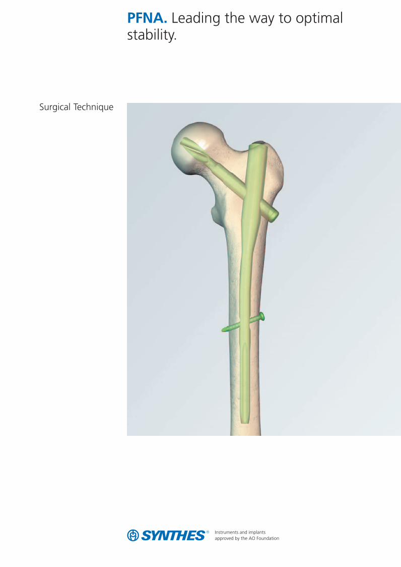
PFNA. Leading the way to optimalstability.
Surgical Technique
0X6.000.398_AB.qxp:0x6.000.398 02.12.2008 17:15 Uhr Seite U1
2 Synthes PFNA Surgical Technique
Contents
PFNA blade 4
Case studies 5
PFNA nail 6
Indications 7
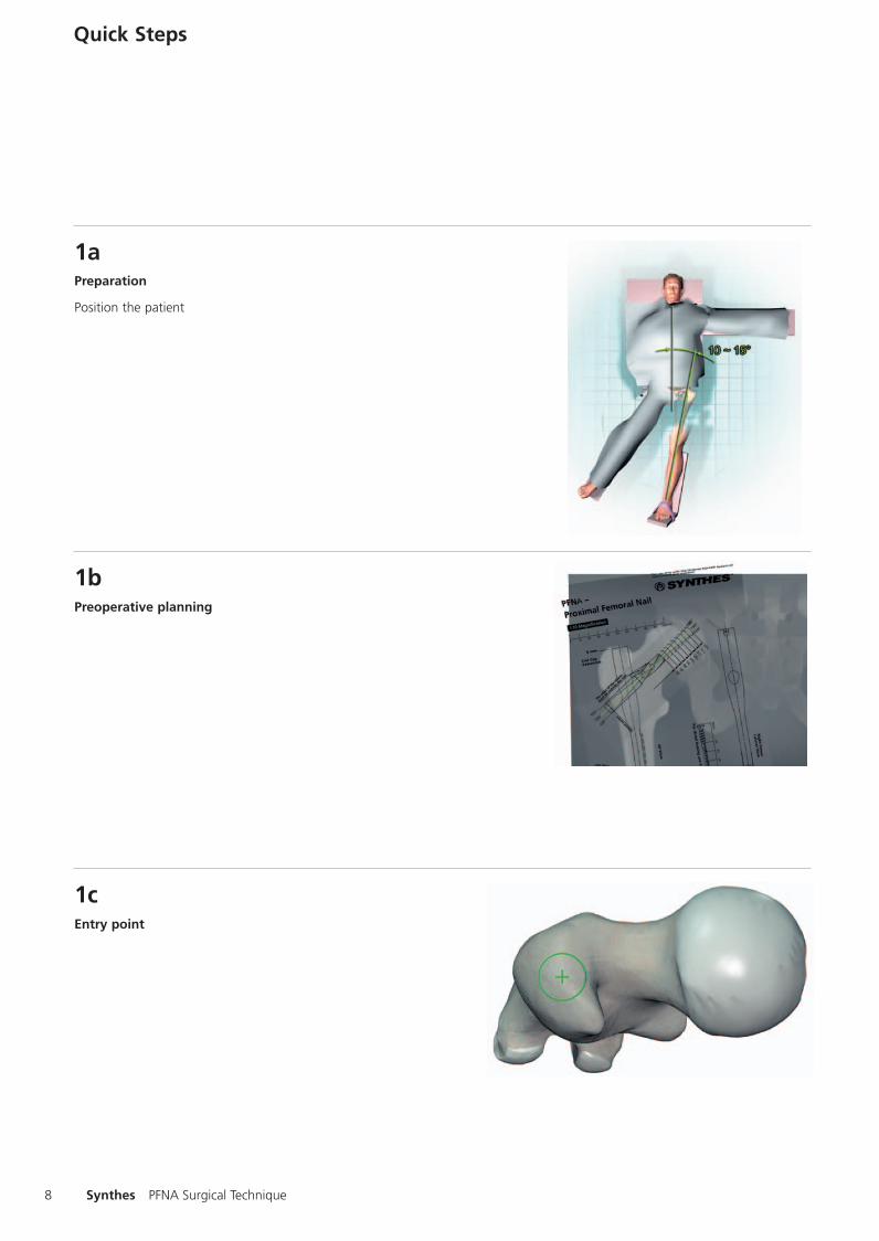
Quick Steps 81a Preparation 82a Insertion of the PFNA 93 Positioning of guide wire for the PFNA blade 104a Insertion of PFNA blade 115a Assembly 126a Insertion of locking bolt and end cap 13
Preparation 141 Patient positioning 142 Determination of CCD angle 143 Fracture reduction 144 Determination of PFNA diameter 155 Surgical approach 15
Surgical technique 161 Determination of PFNA entry point and 16
guide wire insertion 2 Opening of the femur 173 Assembly of PFNA instruments 174 Insertion of the PFNA 185 Preparation of guide wire insertion 196 Guide wire insertion 207 Measuring of PFNA blade length 248 Removal of drill sleeve 249 Opening of lateral cortex for PFNA blade insertion 2410 Drill hole for the PFNA blade 2511 Assembly of PFNA blade and PFNA inserter 2512 Insertion of PFNA blade 2613 Locking of PFNA blade 2714 Removal of protection sleeve 2715 Static distal locking 2816 Dynamic distal locking 2817 Insertion of locking bolt 2918 Instrument removal 2919 Insertion of end cap 30
0X6.000.398_AB.qxp:0x6.000.398 02.12.2008 17:15 Uhr Seite 2

3
Image intensifier control
WarningThis description is not sufficient for immediate application of the instrumentation. Instruction by a surgeon experienced in handling this instrumentation is highly recommended.
Implant removal 311 Removal of PFNA blade 312 Removal of PFNA end cap, PFNA, and locking bolt 31
Insertion depth of PFNA blade 33Insertion depth correction of PFNA blade 33
Cleaning 34Intra- and postoperative cleaning 34
Bibliography 35
Instruments 37
Alternative: aming device 42
Implants 43
0X6.000.398_AB.qxp:0x6.000.398 02.12.2008 17:15 Uhr Seite 3

Bone structure before insertion of the PFNA blade.
Bone structure after PFNA blade insertion – cancellous bone is compacted provid-ing additional anchoring to the PFNA blade.
PFNA blade unlocked
PFNA blade locked
4 Synthes PFNA Surgical Technique
PFNA blade
Rational and angular stability achieved with one single element
Compaction of cancellous bone Inserting the PFNA blade compacts the cancellous bone. This provides additional anchoring to the PFNA blade, which is especially important in osteoporotic bone.
The increased stability caused by bone compaction around the PFNA blade has been biomechanically proven to retard rotation and varus collapse. Such biomechanical tests demonstrated that the PFNA blade had a significantly higher cut-out resis-tance compared to commonly-used screw systems.
Lateral locking-fast and reliable insertion of the PFNA blade
– all surgical steps required to insert the PFNA blade are donethrough the lateral incision
– the PFNA blade is automatically locked to prevent rotation ofthe PFNA blade and the femoral head
0X6.000.398_AB.qxp:0x6.000.398 02.12.2008 17:15 Uhr Seite 4

5
x-rays
27 years, male, AO 31 A3 11 days post-op 11 weeks post-op
85 years, male, AO 31 A2 7 days post-op 171⁄2 weeks post-op
0X6.000.398_AB.qxp:0x6.000.398 02.12.2008 17:15 Uhr Seite 5

6 Synthes PFNA Surgical Technique
PFNA nail
Excellent fit The anatomical design guarantees an opitmal fit in the femur. The nail design has been well proven in over 200 000 cases performed with the PFN.
Optimal stress distribution The flexible PFNA tip eases insertion and avoids stress on the bone at the tip of the PFNA.
The PFNA has medial-lateral angle of 6°.This allows insertion at the tip of the greater trochanter.
PFNA longR = 1500 mm
0X6.000.398_AB.qxp:0x6.000.398 02.12.2008 17:15 Uhr Seite 6

PFNA long
PFNA
7
Indications
Indications
PFNA
– Petrochanteric fractures (31-A1 und 31-A2) – Intertrochanteric fractures (31-A3) – High subtrochanteric fractures
PFNA long
– Low and extended subtrochanteric fractures – Ipsilateral trochanteric fractures – Combination fracuters (in the proximal femoral) – Pathological fractures
Product range
The PFNA is available in 4 sizes: – PFNA, length 240 mm – PFNA small, length 200 mm – PFNA xs, length 170 mm – PFNA long, length 300, 340, 380,
420 mm with bending radius 1500 mm
Several distal locking options
Static dynamic locking can be performed via the aiming arm with PFNA standard, small and xs. The PFNA long allows in addition secondary dynamisation.
static dynamic
static dynamic
0X6.000.398_AB.qxp:0x6.000.398 02.12.2008 17:15 Uhr Seite 7
8 Synthes PFNA Surgical Technique
Quick Steps
Preparation
Position the patient
Preoperative planning
Entry point
1a
1b
1c
0X6.000.398_AB.qxp:0x6.000.398 02.12.2008 17:15 Uhr Seite 8

9
Insertion of the guide wire
– Insertion the guide wire to open the femur – AP and ML control
Open the femur
Insert the PFNA
2a
2b
2c
0X6.000.398_AB.qxp:0x6.000.398 02.12.2008 17:15 Uhr Seite 9
10 Synthes PFNA Surgical Technique
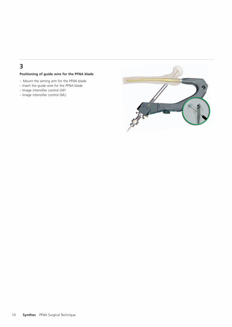
Positioning of guide wire for the PFNA blade
– Mount the aiming arm for the PFNA blade – Insert the guide wire for the PFNA blade – Image intensifier control (AP) – Image intensifier control (ML)
3
0X6.000.398_AB.qxp:0x6.000.398 02.12.2008 17:15 Uhr Seite 10

11
Insertion of PFNA blade
Measure the length for the PFNA blade
Open the lateral cortex for PFNA blade insertion
Drill hole for the PFNA blade
4a
4b
4c
0X6.000.398_AB.qxp:0x6.000.398 02.12.2008 17:15 Uhr Seite 11

12 Synthes PFNA Surgical Technique
Attach the PFNA blade
Attach the PFNA blade to the inserter (turn the inserter anticlockwise to the «attach» marking)
Insert the PFNA blade
Lock the PFNA blade
(turn the inserter clockwise to the «lock» marking)
5a
5b
5c
0X6.000.398_AB.qxp:0x6.000.398 02.12.2008 17:15 Uhr Seite 12

13
Insertion of locking bolt and end cap
Drill hole and measure for distal locking
Insert the locking bolt
Insert the end cap
6a
6b
6c
0X6.000.398_AB.qxp:0x6.000.398 02.12.2008 17:15 Uhr Seite 13

14 Synthes PFNA Surgical Technique
Preparation
1Patient positioning
Position the patient supine on an extension table or a radiolu-cent operating table. Abduct the unaffected leg as far as possible and place it on a leg support, so that it does allow free fluoroscopic examinations. This should be tested preope-ratively. For an unimpeded access to the medullary cavity, abduct the upper body by about 10–15° to the unaffected side (or adduct the affected leg by 10–15°).
2Determination of CCD angle
Take a preoperative AP radiography of the unaffected leg. Determine the CCD angle using a goniometer or the preopera-tive planning template.
3Fracture reduction
Perform closed reduction of the fracture under image intensi-fier control. Carry out open reduction, if the result is not satisfactory.
Note: Exact anatomical reduction and secure fixation of the patient to the operating table are essential for easy handling and a good surgical result.
0X6.000.398_AB.qxp:0x6.000.398 02.12.2008 17:15 Uhr Seite 14

15
4Determination of PFNA diameter
Determine the distal PFNA diameter by placing the preoperative planning template over the isthmus on an AP radiography.
Alternative:Use image intensifier control to place the Radiographic Ruler(309.602) on the femur and position the square marking over the isthmus. If the transition of medullary space/cortex is still visible on both sides of the marking, the corresponding PFNA diameter may be used.
If the intramedullary canal is too narrow, select a smaller size PFNA diameter or ream to a diameter that is at least 1 mm larger than that of the planned PFNA.
Note: The use of a too large PFNA can provoke loss of reduc-tion or an iatrogenic fracture.
5Surgical approach
Palpate the trochanter major.
Make a 5 cm incision approximately 5 to 10 cm proximal from the tip of the greater trochanter. Make a parallel incision of the fasciae of the gluteus medius and split the glutaeus medius in line with the fibres. When using the Insertion Handle for PFN (357.020), extend the incision distally.
0X6.000.398_AB.qxp:0x6.000.398 02.12.2008 17:15 Uhr Seite 15
16 Synthes PFNA Surgical Technique
Surgical Technique
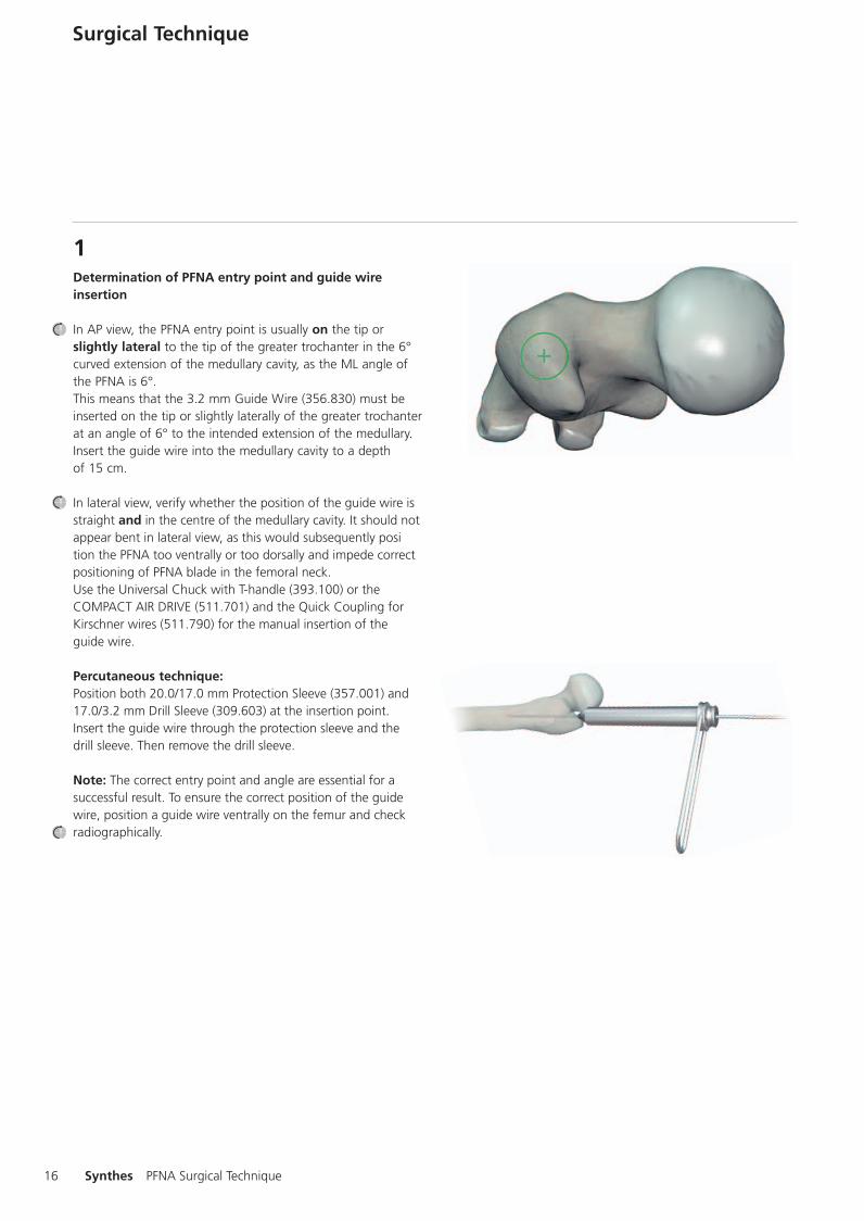
1Determination of PFNA entry point and guide wireinsertion
In AP view, the PFNA entry point is usually on the tip orslightly lateral to the tip of the greater trochanter in the 6°curved extension of the medullary cavity, as the ML angle ofthe PFNA is 6°.This means that the 3.2 mm Guide Wire (356.830) must beinserted on the tip or slightly laterally of the greater trochanterat an angle of 6° to the intended extension of the medullary.Insert the guide wire into the medullary cavity to a depthof 15 cm.
In lateral view, verify whether the position of the guide wire isstraight and in the centre of the medullary cavity. It should notappear bent in lateral view, as this would subsequently position the PFNA too ventrally or too dorsally and impede correctpositioning of PFNA blade in the femoral neck.Use the Universal Chuck with T-handle (393.100) or the COMPACT AIR DRIVE (511.701) and the Quick Coupling forKirschner wires (511.790) for the manual insertion of theguide wire.
Percutaneous technique:Position both 20.0/17.0 mm Protection Sleeve (357.001) and17.0/3.2 mm Drill Sleeve (309.603) at the insertion point.Insert the guide wire through the protection sleeve and thedrill sleeve. Then remove the drill sleeve.
Note: The correct entry point and angle are essential for asuccessful result. To ensure the correct position of the guidewire, position a guide wire ventrally on the femur and checkradiographically.
0X6.000.398_AB.qxp:0x6.000.398 02.12.2008 17:15 Uhr Seite 16

17
2Opening of the femur
Guide the cannulated 17.0 mm Drill Bit (309.600) through the 20.0/17.0 mm Protection Sleeve (357.001) over the 3.2 mm Guide Wire (356.830) and drill with the Universal Chuck with T-handle (393.100) as far as the stop on the protection sleeve. Remove the protection sleeve and the guide wire.
Note: It is recommended to open the femur by power tool at high speed or carefully by hand. To prevent dislocating the fracture fragments, avoid lateral movements or excessive compression forces.
3Assembly of PFNA instruments
Guide the Connecting Screw (357.021) through the Insertion Handle (357.012) and secure the PFNA to the insertion handle using the Hexagonal Wrench with T-handle (357.023). The diameter of the PFNA has already been determined during surgical preparation.
Note: Ensure that the connection between PFNA and insertion handle is tight (retighten, if necessary) to avoid deviations when inserting the PFNA blade through the insertion handle. Do not attach the aiming arm yet.
0X6.000.398_AB.qxp:0x6.000.398 02.12.2008 17:15 Uhr Seite 17

18 Synthes PFNA Surgical Technique
4Insertion of the PFNA
Use image intensifier control to insert the PFNA.
Carefully insert the PFNA manually as far as possible into the femoral opening. Slight twisting hand movements help inser-tion. If the PFNA cannot be inserted, select a smaller size PFNA diameter or ream the medullary cavity to a diameter that is at least 1 mm larger than that of the selected nail.
If necessary, light blows with the Hammer (399.420) on the protection shield of the insertion handle can support the insertion of the PFNA.
The correct PFNA insertion depth is reached, as soon as the projected PFNA blade is positioned in the lower half of the femoral neck. Placing a ruler on the AP view allows checking the position of the PFNA blade. A too cranial or too caudal PFNA position should be avoided as it can lead to malposition of the PFNA blade.
The anteversion can be determined by inserting a guide wire ventral to the femoral neck in the femoral head. In the medio-lateral view, place the insertion guide parallel to the guide wire to align the correct rotation of the PFNA.
Remove all guide wires. Do not reuse, but dispose of the guide wires.
Note: – Always ensure that the PFNA is firmly attached to the
insertion handle. – Use only light blows on the protection shield of the
insertion handle. Avoid unnecessary use of force to prevent loss of reductionor an iatrogenic fracture.
0X6.000.398_AB.qxp:0x6.000.398 02.12.2008 17:15 Uhr Seite 18
1
19
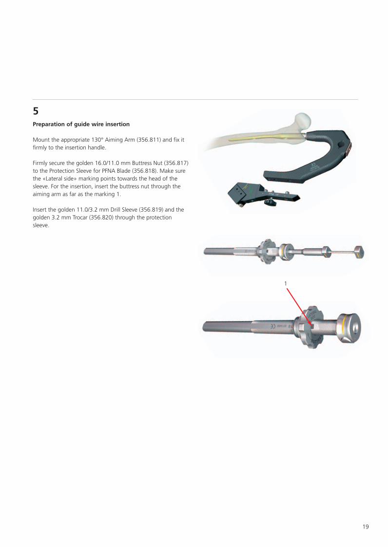
5Preparation of guide wire insertion
Mount the appropriate 130° Aiming Arm (356.811) and fix it firmly to the insertion handle.
Firmly secure the golden 16.0/11.0 mm Buttress Nut (356.817) to the Protection Sleeve for PFNA Blade (356.818). Make sure the «Lateral side» marking points towards the head of the sleeve. For the insertion, insert the buttress nut through the aiming arm as far as the marking 1.
Insert the golden 11.0/3.2 mm Drill Sleeve (356.819) and the golden 3.2 mm Trocar (356.820) through the protection sleeve.
0X6.000.398_AB.qxp:0x6.000.398 02.12.2008 17:15 Uhr Seite 19

20 Synthes PFNA Surgical Technique
6Guide wire insertion
Advance the entire sleeve assembly for PFNA blade through the aiming arm to the skin. See marking on the 130° Aiming Arm (356.811). Make a stab incision in the area of the trocar tip. Advance the sleeve assembly through the soft tissues in direction of the lateral cortex until it clicks into the aiming arm.
Note: Ensure that the sleeve assembly clicks into the aiming arm. Otherwise it does not guarantee the exact position of the PFNA blade.
0X6.000.398_AB.qxp:0x6.000.398 02.12.2008 17:15 Uhr Seite 20

21
Insert the sleeve assembly as far as the lateral cortex. Advance the Protection Sleeve (356.818) to the lateral cortex using slight clockwise turns of the Buttress Nut (356.817). Prepare the passage of the protection sleeve by turning the internal golden 11.0/3.2 mm Drill Sleeve (356.819).
Note: The sleeve assembly must be in contact with the bone during the entire blade implantation. Do not tighten the buttress nut too firmly as this could impair the precision of the insertion handle and sleeve assembly.
0X6.000.398_AB.qxp:0x6.000.398 02.12.2008 17:15 Uhr Seite 21

22 Synthes PFNA Surgical Technique
Remove the trocar. Insert a new 3.2 mm Guide Wire (356.830) through the golden 11.0/3.2 mm Drill Sleeve (356.819) into the bone. Verify both direction and position under image intensifier in AP and lateral view. In the AP view, the position of the guide wire should be in the lower half of the femoral neck. In lateral view, the wire should be positionedin the in the centre of the femoral neck. Insert the guide wire subchondrally into the femoral head, but at a distance of least 5 mm from the joint.
Note: If the PFNA or the guide wire has to be repositioned, remove the guide wire, release the sleeve assembly with buttress nut from the aiming arm by pressing the button on the clamp device and remove it. The PFNA can be repositioned only by rotation, deeper insertion or partial retraction. Reinsert the sleeve assembly and turn the buttress nut clock-wise to position the assembly on the bone. Reinsert the guide wire.
0X6.000.398_AB.qxp:0x6.000.398 02.12.2008 17:15 Uhr Seite 22

23
Optional technique for antirotation wires: In very unstable fractures, insert an additional guide wire to prevent rotation. Leave the golden 11.0/3.2 mm Drill Sleeve (356.819) in place in the golden 16.0/11.0 mm Protection Sleeve (356.818) when applying this technique. After having inserted the guide wire into the femoral head, secure the Aiming Jig for antirotation wire (356.826) either anterior or posterior to the aiming arm. Secure the position des antirotation wire by tightening the hexagonal nut. Insert the 5.6/3.2 mm Drill Sleeve (356.827) into the Aiming Jig for antirotation wire (356.826). Make a stab incision and insert the drill sleeve to the bone.
Use image intensifier control to insert a 3.2 mm Guide Wire (356.830) into the femoral head.If a second antirotation wire is necessary, use the same procedure to insert it into the femoral head.
Note: In axial view, the antirotation wire will approach, but not touch the blade tip. This antirotation wire fixes the femoral head only temporarily and will be removed after the insertion of the blade.
0X6.000.398_AB.qxp:0x6.000.398 02.12.2008 17:15 Uhr Seite 23

24 Synthes PFNA Surgical Technique
7Measuring of PFNA blade length
Verify the position of the guide wire in AP and lateral view before measuring the length.
Guide the Measuring Device for 3.2 mm Guide Wire (356.829) over the guide wire, advance it to the protection sleeve and determine the length of the required blade. The measuring device indicates the exact length of the guide wire in the bone ensuring that the position of the PFNA blade will be flush with the tip of the guide wire. The correct position of the PFNA blade is approximately 5–10 mm below the joint level. If the guide wire’s position is subchondral, subtract 5–10 mm, as in the DHS system, to position the PFNA blade correctly.
8Removal of drill sleeve
Carefully remove the golden 11.0/3.2 mm Drill Sleeve (356.819) without changing the position of the guide wire.
9Opening of lateral cortex for PFNA blade insertion
Push the cannulated 11.0 mm Drill Bit (356.822) over the 3.2 mm Guide Wire (356.830). Drill to the stop. This opens the lateral cortex.
Note: if the guide wire has been bent slightly during insertion, guide the drill bit over it using carefully forward and backward movements. However, if the wire has been bent to a greater extent, reinsert it or replace it by a new guide wire. Otherwise, the tip of the drill bit risks to break off.
0X6.000.398_AB.qxp:0x6.000.398 02.12.2008 17:15 Uhr Seite 24
25
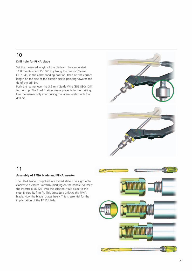
10Drill hole for PFNA blade
Set the measured length of the blade on the cannulated 11.0 mm Reamer (356.821) by fixing the Fixation Sleeve (357.046) in the corresponding position. Read off the correct length on the side of the fixation sleeve pointing towards the tip of the drill bit. Push the reamer over the 3.2 mm Guide Wire (356.830). Drill to the stop. The fixed fixation sleeve prevents further drilling. Use the reamer only after drilling the lateral cortex with the drill bit.
11Assembly of PFNA blade and PFNA inserter
The PFNA blade is supplied in a locked state. Use slight anti-clockwise pressure («attach» marking on the handle) to insert the Inserter (356.823) into the selected PFNA blade to the stop. Ensure its firm fit. This procedure unlocks the PFNA blade. Now the blade rotates freely. This is essential for the implantation of the PFNA blade.
0X6.000.398_AB.qxp:0x6.000.398 02.12.2008 17:15 Uhr Seite 25

26 Synthes PFNA Surgical Technique
12Insertion of PFNA blade
Insert both blade and Inserter (356.823) over the 3.2 mm Guide Wire (356.830) through the protection sleeve. In view of the particular shape of the PFNA blade, align it with the protection sleeve for insertion (see marking on the protection sleeve), pressing at the same time the button on the protec-tion sleeve. Hold the golden handle of the inserter and manually insert the blade over the guide wire as far as possible into the femoral head. Insert the PFNA blade to the stop by hammering lightly with the Hammer (399.420).
Use image intensification to check the position of the PFNA blade.
Note: Inserting the blade to the stop is important, as the inserter has to click into the protection sleeve. Do not use unnecessary force when inserting the PFNA blade.
0X6.000.398_AB.qxp:0x6.000.398 02.12.2008 17:15 Uhr Seite 26

Unlocked PFNA blade Locked PFNA blade
27
13Locking of PFNA blade
Turn the inserter clockwise to the stop (see «lock» marking on the handle). The PFNA blade is now locked. Verify PFNA blade locking intraoperatively. The PFNA blade is locked if all gaps are closed. If the PFNA blade cannot be locked, remove it and replace it by a new PFNA blade (see implant removal, point 1, p. 28).
Note: Gliding of the PFNA blade is guaranteed.
Press the button on the protection sleeve to remove the inserter. Remove and dispose of the guide wire.
14Removal of protection sleeve
Release and remove the protection sleeve and the buttress nut by pressing the button on the clamp device of the aiming arm.
0X6.000.398_AB.qxp:0x6.000.398 02.12.2008 17:15 Uhr Seite 27
28 Synthes PFNA Surgical Technique
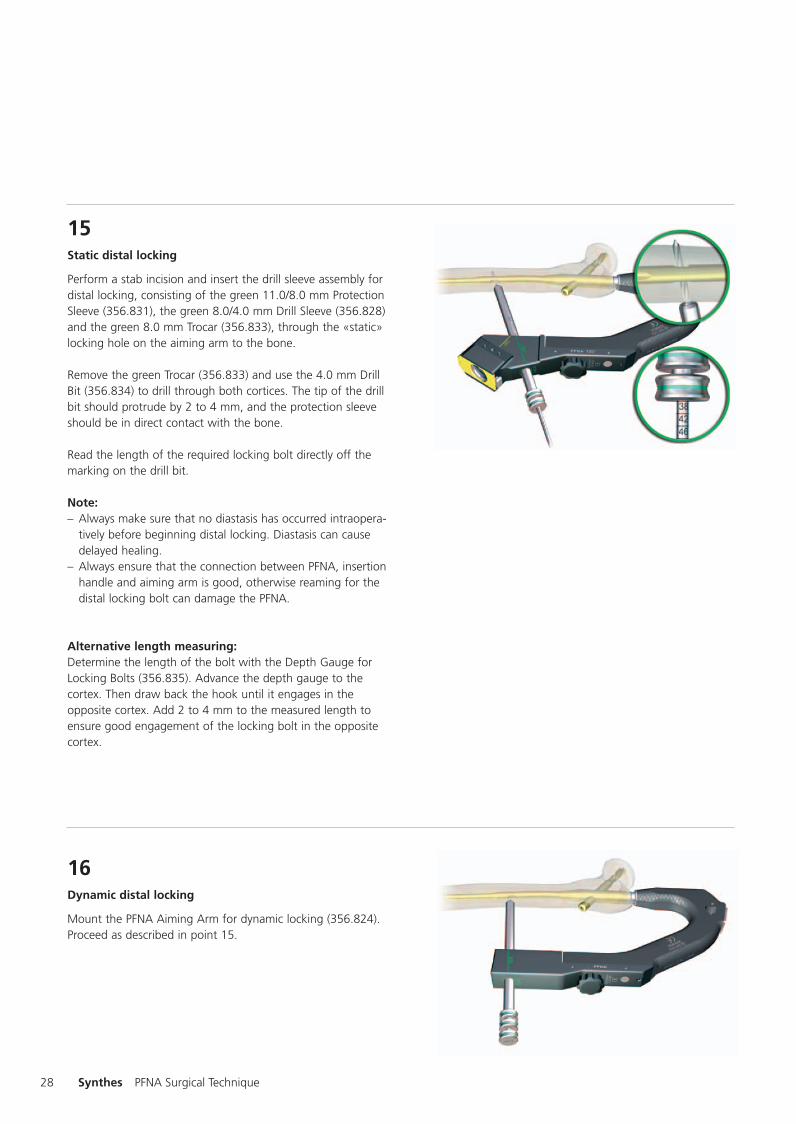
15Static distal locking
Perform a stab incision and insert the drill sleeve assembly for distal locking, consisting of the green 11.0/8.0 mm Protection Sleeve (356.831), the green 8.0/4.0 mm Drill Sleeve (356.828) and the green 8.0 mm Trocar (356.833), through the «static» locking hole on the aiming arm to the bone.
Remove the green Trocar (356.833) and use the 4.0 mm Drill Bit (356.834) to drill through both cortices. The tip of the drill bit should protrude by 2 to 4 mm, and the protection sleeve should be in direct contact with the bone.
Read the length of the required locking bolt directly off the marking on the drill bit.
Note: – Always make sure that no diastasis has occurred intraopera-
tively before beginning distal locking. Diastasis can cause delayed healing.
– Always ensure that the connection between PFNA, insertionhandle and aiming arm is good, otherwise reaming for thedistal locking bolt can damage the PFNA.
Alternative length measuring: Determine the length of the bolt with the Depth Gauge for Locking Bolts (356.835). Advance the depth gauge to the cortex. Then draw back the hook until it engages in the opposite cortex. Add 2 to 4 mm to the measured length to ensure good engagement of the locking bolt in the opposite cortex.
16Dynamic distal locking
Mount the PFNA Aiming Arm for dynamic locking (356.824). Proceed as described in point 15.
0X6.000.398_AB.qxp:0x6.000.398 02.12.2008 17:15 Uhr Seite 28

29
17Insertion of locking bolt
Insert the locking bolt through the protection sleeve using the large Hexagonal Screwdriver (314.260).
18Removal of instruments
Remove the protection sleeve and the aiming arm. Use the hexagonal socket to loosen the connecting screw and remove the insertion handle.
0X6.000.398_AB.qxp:0x6.000.398 02.12.2008 17:15 Uhr Seite 29

30 Synthes PFNA Surgical Technique
19Insertion of end cap
Use the end cap with 0 mm extension if the nail end is flush with the upper edge of the trochanter major.
Insert the hook of the Guide Wire with Hook (356.717) through the selected end cap. Then guide the 4/11 mm Hexagonal Screwdriver Shaft (356.714) over the guide wire to the end cap. The end cap is retained automatically as soon as this connection is established.
Guide the cannulated end cap to the proximal end of the nail. Use the 11 mm Ratchet Wrench (321.200) to secure the end cap. Fully insert the end cap into the nail. The last turns of the end cap in the nail will offer increased resistance. Continue to turn until the stop of the end cap touches the proximal nail end. This prevents the end cap from slipping out. Remove the hexagonal screwdriver shaft, the ratchet wrench and the guide wire.
0X6.000.398_AB.qxp:0x6.000.398 02.12.2008 17:15 Uhr Seite 30

31
Implant removal
1Removal of PFNA blade
After an incision through the old scars, locate the PFNA blade by palpation or under image intensification. Insert the 3.2 mm Guide Wire (356.830). Push the Extraction Screw (356.825) over the guide wire and use gentle pressure to turn it anti-clockwise into the PFNA blade (see «unlock» marking).
Use light hammer blows with the Slotted Hammer (357.026) to remove and dispose of the PFNA blade.
2Removal of PFNA end cap, PFNA, and locking bolt
First remove the PFNA End Cap (473.155S). Insert the hook of the Guide Wire with Hook (356.717) through the end cap. Then guide the 4/11 mm Hexagonal Screwdriver Shaft (356.714) over the guide wire to the end cap. As soon as this connection is established, remove the end cap using the 11 mm Ratchet Wrench (321.200). Remove the PFNA. Attach the Guide Rod for PFN* (357.071) to the PFNA, and only then use the Hexagonal Screwdriver (314.260) to remove the distal locking bolt. Mount the large Holding Sleeve (314.280) onto the hexagonal screwdriver to facilitate removal of the locking bolt.
0X6.000.398_AB.qxp:0x6.000.398 02.12.2008 17:15 Uhr Seite 31

32 Synthes PFNA Surgical Technique
Note: Remove the locking bolt only after attaching the guide rod to the PFNA. This prevents the PFNA from rotating in the bone.
Attach the Slotted Hammer (357.026) to the guide rod to remove the PFNA. Ensure that the guide rod fits firmly into the PFNA. Tighten with the 4.5 mm Pin Wrench (321.170). Use gentle hammer blows to extract the PFNA from the femur.
0X6.000.398_AB.qxp:0x6.000.398 02.12.2008 17:15 Uhr Seite 32

33
Insertion depth of the PFNA blade
Correct the insertion depth of the PFNA blade
Remove the inserter, the sleeve assembly and the aiming arm. Use gentle anticlockwise pressure to insert the Extraction Screw (356.825) over the guide wire into the PFNA blade (see «unlock» marking). Advance the now unlocked PFNA blade to the desired insertion depth by applying gentle blows with the Slotted Hammer (357.026). Turning it clockwise to the stop allows relocking of the PFNA blade.
0X6.000.398_AB.qxp:0x6.000.398 02.12.2008 17:15 Uhr Seite 33

34 Synthes PFNA Surgical Technique
Cleaning
Intra- and postoperative cleaning
Use the 2.8 mm Stylet (319.460) or the long 2.8 mm Cleaning Stylet (357.009, length 450 mm) for intraoperative cleaning of the instrument cannulations. Clean the instruments postoperatively with the 2.8 mm Stylet (319.460) and the 2.9 mm Cleaning Brush for cannulated instruments (319.240).
Subject to modifications.
0X6.000.398_AB.qxp:0x6.000.398 02.12.2008 17:15 Uhr Seite 34

35
Bibliography
The AO/ASIF-proximal femoral nail (PFN) a new device for thetreatment of unstable proximal femoral fracturesR. K. J. Simmermacher, A. M. Bosch, Chr. Van der WerkenInjury 340 (1999) 327 – 332
Treatment of unstable trochanteric fractures Randomisedcomparison of the Gamma Nail and the Proximal Femoral NailI. B. Schipper, E. W. Steyerberg, R. M. Castelein, F. H. W. K. vander Heijden, P. T. den Hoed, A. J. H. Kerver, A. B. van VugtJ Bone Joint Surg [Br] 2004;86-B:86-94.Received 17 April 2003; Accepted after revision 11 August2003
Treatment of ipsilateral fractures of the femur shaft and theproximal femur-review of the therapies and current manage-ment [d]N.P. Haas, M. Schütz, C. Mauch, R. Hoffmann, N.P. SüdkampZentralblatt für Chirurgie 120 (1995) 856 – 861
Method of Treatment of Proximal Femoral Fractures: Choice ofthe ImplantP. RegazzoniProximal Femoral Fractures, Volume 2, Chapter 7 Part III
The AO/ASIF Proximal Femoral Nail (PFN) for the Treatment ofUnstable Trochanteric Femoral FracturesG. Al-yassari, R.J. Langstaff, J.W.M. Jones, M. Al-Lamiinjury, Int. J. Care Injured 33 (2002) 395 – 399
Osteosynthesis versus Endoprosthesis in treamtent of unstableIntracapsular Hip Fraktures in the Elderly: A RandomisedClinical TrialA.B. van Vugt Proximal Femoral Fractures, Volume 2, Chapter 17
Functional Results after Treatment of Hip Fracture:a Multicenter, Prospective Study in 215 PatientsVeronica C.M. Koot, Petra H.M. Peeters, Justin R. de Jong,Geert J. Clevers, Christiaan van der WerkenEuropean Journal of Surgery 2000; 166: 480-485
Pertrochanteric Fractures - Is there an Adavantage to an Intra-medullary Nail?Marc Saudan, Anne Lübbeke, Christophe Sadowski, NicolasRiand, Richard Stern, Pierre HoffmeyerJournal of Orthopaedic Trauma Vol. 16, No. 6, pp. 386–393
0X6.000.398_AB.qxp:0x6.000.398 02.12.2008 17:15 Uhr Seite 35
36 Synthes PFNA Surgical Technique
The Value of the Tip-Apex Distance in Predicting Failure ofFixation of Peritrochanteric Fractures of the HipMichael R. Baumgaertner, Stephen L. Curtin, Dieter M.Linddkog, John M. KeggiJ Bone Joint Surg Am. 1995 Jul;77(7):1058-64Mechanical effects of different localization of the point ofentry in femoral nailing.R.M. Strand, A.O. Molster, L.B. Engesaeter, N.R. Gjerdet, T.Orner.Arch Orthop Trauma Surg (1998), 117, pp: 35-38
Anatomy of the medial femoral circumflex artery and itssurgical implications.Emanuel Gautier, Katharine Ganz, Nathalie Krügel, ThomasGill, Reinhold GanzThe Journal of Bone and Joint Surgery, Vol. 82-B, No. 5, July2000
Entry point soft tissue damage in antegrade femoral nailing :a cadaver studyC. Dora, M. Leunig, M. Beck, D. Rothenfluh, R. Ganz.Journal of Orthopedic Trauma. Vol. 15, No. 7, pp. 488-493.(2001)
0X6.000.398_AB.qxp:0x6.000.398 02.12.2008 17:15 Uhr Seite 36

37
Instruments
309.600 Drill Bit 17.0 mm dia., cannulated
309.602 Radiographic Ruler for PFNA
309.603 Drill Sleeve 17.0/3.2 mm, for no. 357.001
314.260 Screwdriver, hexagonal, large
319.240 Cleaning Brush 2.9 mm dia.
319.970 Screw Forceps, self-retaining, length 85 mm
321.160 Combination Wrench 11 mm, length 140 mm
321.170 Pin Wrench
351.050 Tissue Protector
0X6.000.398_AB.qxp:0x6.000.398 02.12.2008 17:15 Uhr Seite 37

38 Synthes PFNA Surgical Technique
356.714 Screwdriver Shaft, hexagonal, 4.0/11.0 mm
356.715 Screwdriver Shaft, hexagonal 11.0/11.0 mm
356.717 Guide Wire 2.8 mm dia., with Hook, length 460 mm
356.810* Aiming Arm for PFNA Blade, 125° 356.811* Aiming Arm for PFNA Blade, 130° 356.812* Aiming Arm for PFNA Blade, 135° 356.813** Aiming Arm for PFNA Blade, 125° 356.814** Aiming Arm for PFNA Blade, 130°
356.817 Buttress Nut for PFNA Blade
356.818 Protection Sleeve 16.0 /11.0 mm for PFNA Blade (golden)
356.819 Drill Sleeve 11.0 /3.2 mm for PFNA Blade (golden)
356.820 Trocar 3.2 mm dia., for PFNA Blade (golden)
356.821 Reamer 11.0 mm dia., cannulated, for PFNA Blade
*for PFNA standard and PFNA long **for PFNA small, XS and long
0X6.000.398_AB.qxp:0x6.000.398 02.12.2008 17:15 Uhr Seite 38

39
356.822 Drill Bit 11.0 mm dia., cannulated, for PFNA Blade
356.823 Inserter for PFNA Blade
356.824 PFNA Aiming Arm for dynamic locking
356.825 Extraction Screw for PFNA Blade
356.826 Aiming Jig for antirotation wire
356.827 Drill Sleeve 5.6/3.2 mm for no. 356.826
356.828 Drill Sleeve 8.0/4.0 mm (green)
356.829 Measuring Device for 3.2 mm Guide Wire
356.830 Guide Wire 3.2 mm dia., for PFNA Blade
0X6.000.398_AB.qxp:0x6.000.398 02.12.2008 17:15 Uhr Seite 39

40 Synthes PFNA Surgical Technique
356.831 Protection Sleeve 11.0/8.0 mm (green)
356.832 Wrench for PFNA Blade
356.833 Trocar 4.0 mm dia. (green)
356.834 Drill Bit 4.0 mm dia.
356.835 Depth Gauge for Locking Bolts
357.001 Protection Sleeve 20.0/17.0 mm
357.009 Cleaning Stylet 2.8 mm dia.
357.012 Insertion Handle for PFN* and PFN* long
357.013 Threaded Plug for Guide Rod for PFN, for no. 357.012
*Fits also PFNA
0X6.000.398_AB.qxp:0x6.000.398 02.12.2008 17:15 Uhr Seite 40

41
357.023 Socket, hexagonal, with T-handle
357.021 Connecting Screw for PFN*, for no. 357.012
357.026 Slotted Hammer 400g, detachable
357.046 Fixation Sleeve for no. 357.045
357.071 Guide Rod for PFN*
393.100 Universal Chuck with T-handle
399.420 Hammer
185.280 PFNA Instrument Set in VARIO Case
385.222 Screw Rack for 4.9 mm locking bolts
*Fits also PFNA
0X6.000.398_AB.qxp:0x6.000.398 02.12.2008 17:15 Uhr Seite 41
42 Synthes PFNA Surgical Technique
685.280 Vario Case PFNA Instruments 1
685.282 Vario Case PFNA Instruments 2
689.530 Lid for Vario Case
Alternative: aiming device
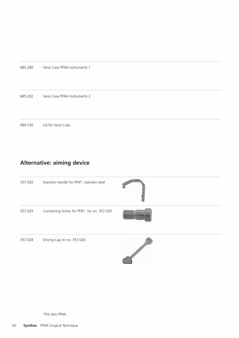
357.020 Insertion Handle for PFN*, stainless steel
357.029 Connecting Screw for PFN*, for no. 357.020
357.028 Driving Cap to no. 357.020
*Fits also PFNA
0X6.000.398_AB.qxp:0x6.000.398 02.12.2008 17:15 Uhr Seite 42

43
Implants
PFNA standard, sterile
TAN Diameter Length CCD angle
472.260S 10 mm 240 mm 125°472.261S 11 mm 240 mm 125°472.262S 12 mm 240 mm 125°472.265S 10 mm 240 mm 130°472.266S 11 mm 240 mm 130°472.267S 12 mm 240 mm 130°472.270S 10 mm 240 mm 135°472.271S 11 mm 240 mm 135°472.272S 12 mm 240 mm 135°472.400S 9 mm 240 mm 125°472.401S 9 mm 240 mm 130°
PFNA small, sterile
TAN Diameter Length CCD angle
472.370S 10 mm 200 mm 125°472.371S 11 mm 200 mm 125°472.372S 12 mm 200 mm 125°472.375S 10 mm 200 mm 130°472.376S 11 mm 200 mm 130°472.377S 12 mm 200 mm 130°472.430S 9 mm 200 mm 125°472.431S 9 mm 200 mm 130°
PFNA XS, sterile
TAN Diameter Length CCD angle
472.385S 10 mm 170 mm 125°472.386S 11 mm 170 mm 125°472.387S 12 mm 170 mm 125°472.390S 10 mm 170 mm 130°472.391S 11 mm 170 mm 130°472.392S 12 mm 170 mm 130°472.436S 9 mm 170 mm 125°472.437S 9 mm 170 mm 130°
0X6.000.398_AB.qxp:0x6.000.398 02.12.2008 17:15 Uhr Seite 43
44 Synthes PFNA Surgical Technique
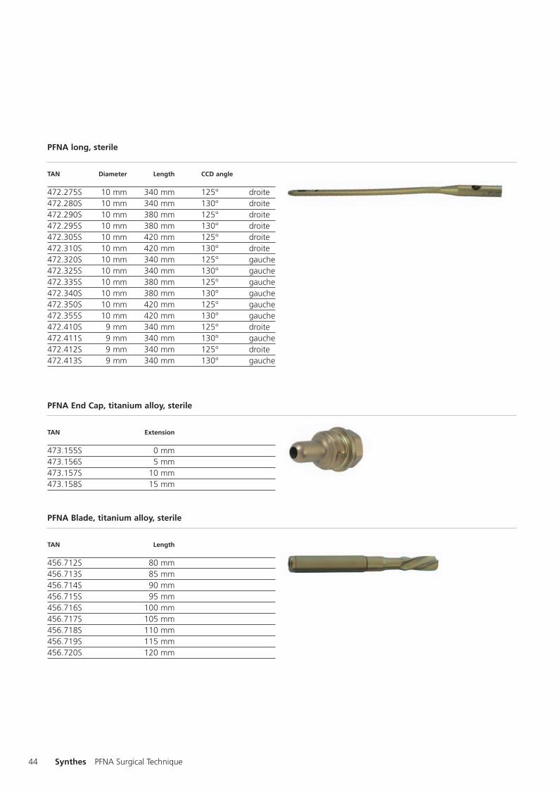
PFNA long, sterile
TAN Diameter Length CCD angle
472.275S 10 mm 340 mm 125° droite472.280S 10 mm 340 mm 130° droite472.290S 10 mm 380 mm 125° droite472.295S 10 mm 380 mm 130° droite472.305S 10 mm 420 mm 125° droite472.310S 10 mm 420 mm 130° droite472.320S 10 mm 340 mm 125° gauche472.325S 10 mm 340 mm 130° gauche472.335S 10 mm 380 mm 125° gauche472.340S 10 mm 380 mm 130° gauche472.350S 10 mm 420 mm 125° gauche472.355S 10 mm 420 mm 130° gauche472.410S 9 mm 340 mm 125° droite472.411S 9 mm 340 mm 130° gauche472.412S 9 mm 340 mm 125° droite472.413S 9 mm 340 mm 130° gauche
PFNA End Cap, titanium alloy, sterile
TAN Extension
473.155S 0 mm473.156S 5 mm473.157S 10 mm473.158S 15 mm
PFNA Blade, titanium alloy, sterile
TAN Length
456.712S 80 mm456.713S 85 mm456.714S 90 mm456.715S 95 mm456.716S 100 mm456.717S 105 mm456.718S 110 mm456.719S 115 mm456.720S 120 mm
0X6.000.398_AB.qxp:0x6.000.398 02.12.2008 17:15 Uhr Seite 44

45
4.9 mm Locking Bolt, self-tapping
TAN TANUnsterile Sterrile Length
459.260 459.260S 26 mm459.280 459.280S 28 mm459.300 459.300S 30 mm459.320 459.320S 32 mm459.340 459.340S 34 mm459.360 459.360S 36 mm459.380 459.380S 38 mm459.400 459.400S 40 mm459.420 459.420S 42 mm459.440 459.440S 44 mm459.460 459.460S 46 mm459.480 459.480S 48 mm459.500 459.500S 50 mm459.520 459.520S 52 mm459.540 459.540S 54 mm459.560 459.560S 56 mm459.580 459.580S 58 mm459.600 459.600S 60 mm459.640 459.640S 64 mm459.680 459.680S 68 mm459.720 459.720S 72 mm459.740 459.740S 74 mm459.760 459.760S 76 mm459.800 459.800S 80 mm459.850 459.850S 85 mm459.900 459.900S 90 mm459.950 459.950S 95 mm459.960 459.960S 100 mm
0X6.000.398_AB.qxp:0x6.000.398 02.12.2008 17:15 Uhr Seite 45

0X6.000.398_AB.qxp:0x6.000.398 02.12.2008 17:15 Uhr Seite 46

0X6.000.398_AB.qxp:0x6.000.398 02.12.2008 17:15 Uhr Seite U3

0123 036.
000.
398
SM
_707
818
AB
310
6003
4 ©
Syn
thes
20
06
Vario
Cas
e an
d C
ompa
ct A
ir D
rive
are
trad
emar
ks o
f Sy
nthe
s S
ubje
ct t
o m
odifi
catio
ns
Presented by:
Ö036.000.398öAB$ä
0X6.000.398_AB.qxp:0x6.000.398 02.12.2008 17:15 Uhr Seite U4