the tampa electric integrated gasification combined-cycle ... · the tampa electric integrated...
TRANSCRIPT


TOPICAL REPORT NUMBER 6 OCTOBER 1996
The Tampa ElectricIntegrated GasificationCombined-Cycle Project
Demonstration of an Advanced250 Megawatt Integrated GasificationCombined-Cycle Power Plant
A report on a project conducted jointlyunder a cooperative agreement between:
The U.S. Department of Energy and Tampa Electric Company

Cover image: The Polk Power Plant site as seen from across the lake in early evening.Photography courtesy of Lee Schmoe, Bechtel Power Corporation.
Preparation and printing of this documentconforms to the general funding provisions ofa cooperative agreement between TampaElectric Company and the U.S. Department ofEnergy. The funding contribution of theindustrial participant permitted inclusion ofmulticolored artwork and photographs at noadditional expense to the U.S. Government.
T E C H N O L O G Y
The Tampa ElectricIntegrated GasificationCombined-Cycle Project
Introduction and Executive Summary ........................................................................ 2
Background ................................................................................................................ 4
Project Benefits ......................................................................................................... 6
Project Description .................................................................................................... 7
Environmental Considerations ................................................................................. 14
Costs/Schedule/Demonstration Milestones .............................................................. 15
Preliminary Results .................................................................................................. 16
Future Developments ............................................................................................... 17
Clean Coal Technology Program ............................................................................. 18
Contacts ................................................................................................................... 19
Bibliography ............................................................................................................ 20
List of Acronyms and Abbreviations ....................................................................... 21

Introduction andExecutive Summary
Coal is America’s most abundant fossil
fuel. Its combustion creates the steam that
produces 65 percent of this country’s elec-
tricity. The burning of coal, however, lib-
erates two types of gases that have been
linked to the formation of acid rain: nitro-
gen oxides (NOX) and sulfur dioxide (S02).
With the passage of each successive
piece of clean air legislation over the
years, the electric utility industry has been
made increasingly aware that it would
eventually have to reduce both types of
emissions from existing and new power
plants to environmentally acceptable
levels.
The Clean Coal Technology (CCT)
Demonstration Program is a government
and industry co-funded program to
furnish the U.S. energy marketplace
with advanced, more efficient and
environmentally responsible coal-
utilizing technologies.
A multi-phased effort consisting of five
separate solicitations was administered by
the U.S. Department of Energy (DOE).
Projects selected are a new generation of
innovative coal utilization processes that
are being demonstrated in "showcase"
projects conducted across the country.
These projects are on a scale suffi-
ciently large to demonstrate commercial
worthiness and generate data for design,
construction, operation and technical/eco-
nomic evaluation of full-scale commercial
applications.
2
Integrated GasificationCombined Cycle
Among the technologies being demon-
strated in the CCT program is Integrated
Gasification Combined Cycle (IGCC).
IGCC is an innovative electric power
generation technology that combines
modem coal gasification with gas turbine
and steam power generation technologies.
Syngas produced by a gasifier is cleaned
and burned in a gas turbine to produce
electric power. Heat recovered from the
hot turbine’s exhaust produces steam that
turns a steam turbine generator to produce
more electricity.
IGCC power plants are environmentally
acceptable and easily sited. Atmospheric
emissions of pollutants are low. Water use
is lower than conventional coal-based
generation because gas turbine units
require no cooling water, an especially
important consideration in areas of limited
water resources.
Due to their high efficiency, less coal
is used per megawatt-hour of output,
causing IGCC power plants to emit less
carbon dioxide (C02) to the atmosphere,
thereby decreasing global warming con-
cerns. Less coal use also reduces
disposal requirements for ash or slag if
there is no market for these materials.
Repowering is an excellent applica-
tion for IGCC. Such applications utilize
an existing power plant site and are more
economical than greenfield applications.
Costs are lower because an existing
steam turbine is used, less site develop-
ment is required, and the permitting
process is accelerated.
Both greenfield and repowering IGCC
applications could provide the flexibility
needed for utility compliance planning for
sulfur dioxide (S02) emissions in the next
century. Providing 25 percent of coal-
based electricity by IGCC would result in
emissions less than 0.4 million of the 11.8
million tons/yr of S02 emissions allowable
under the Clean Air Act Amendments
(CAAA).
Modularity and fuel flexibility are other
important attributes of IGCC power plants.
Before the gasifier is constructed, the
combined cycle unit can be operated on
other fuels, such as natural gas or fuel oil, to
provide early power. The size of gas
turbine units can be chosen to meet specific
power requirements. The ability to operate
on multiple fuels allows continued oper-
ation of the gas turbine unit if the gasifier
island is shut down for maintenance or
repairs, or if warranted by fuel costs.
IGCC power plants use plentiful and
relatively inexpensive coal as their fuel. In
the United States there are several hundred
years of reserves, and use of coal helps to
reduce dependence on foreign oil.
IGCC has potential for significant reduc-
tion in capital costs over today’s technolo-
gies, per kW of generation. These, in part,
arise from higher possible efficiencies com-
pared to today’s impressive IGCC values.
Efficiency improvements are expected to
result from design improvements which
increase overall steam and thermal integra-
tion, use of higher firing temperature gas
turbines, and other technology enhance-
ments such as hot-gas cleanup and nitrogen
injections. Other contributors to reduced
capital costs are: economies of scale, re-
duced engineering costs, and improvements
resulting from operating experience.

Executive Summary
The Tampa Electric Integrated Gasifica-
tion Combined-Cycle Project (the Project)
was selected by DOE as a CCT Program
Round III demonstration project. Demon-
stration of this advanced IGCC power plant
was initiated in October, 1996.
The Participant is Tampa Electric
Company (TEC), headquartered in Tampa,
Florida. TEC signed a Cooperative Agree-
ment with DOE to conduct the Project in
July 1992. Its service area includes the city
of Tampa and covers a 2000 square mile
area in west-central Florida.
The greenfield site is located south of
Lakeland, Polk County, Florida. The
Project is demonstrating use of Texaco’s
coal gasification process to fuel an ad-
vanced General Electric gas turbine gen-
erator whose exhaust is integrated with a
heat recovery steam generator (HRSG) and
a steam turbine generator to produce
electric power.
About 96 percent of sulfur contaminants
are removed by a combination of advanced
hot-gas cleanup and conventional cold-gas
cleanup technologies. Ninety percent of
the gasification product gas, termed syngas,
is cleaned by cold-gas cleanup and 10
percent by hot-gas cleanup. Sulfur is
recovered as sulfuric acid and sold, as is
the slag by-product of gasification.
TEC is demonstrating an advanced
moving bed hot-gas desulfurization tech-
nology because of its potential for im-
proving IGCC performance and costs.
A primary potential advantage of hot-
gas cleanup is an increase in power plant
efficiency because cleaning does not
require the syngas to be cooled to near-
ambient temperature (used for cold-gas
cleanup) and resultant energy losses are
eliminated. Further, there is no process
waste water condensate.
The hot moving bed desulfurizationsystem being demonstrated in thisProject captures residual dust containedin the fuel gas, and downstream sinteredmetal barrier filters capture the balance.
In contrast to cold-gas cleanup, the
hot-gas cleanup technologies have not
yet been commercially demonstrated.The combined cycle unit is based on
an advanced General Electric gas turbineunit that produces 192 MWe. The steamturbine produces 121 MWe. Parasiticpower consumes 63 MWe with the netpower output being 250 MWe.
The demonstration also includes inte-
gration of nitrogen from the air separation
plant with the gas turbine. Steam produced
at various gas cooling stages is integrated
with the HRSG and supplies various pro-
cess needs. The facility processes approxi-
mately 2300 tons per day of Pittsburgh No.
8 bituminous coal, with a sulfur content of
2.5—3.5 percent.
S02 emissions will be 0.21 lb/million
Btu input; NOX emissions will be 0.27 lb/
million Btu input. The design heat rate of
the plant is an impressive 8600 Btu/kWh
(40 percent net thermal efficiency) on a
higher heating value basis. The cost of
the Project including land acquisition, site
development and allowance for funds
used during construction (AFUDC) is
about $506 million. DOE is providing
about $142 million.
The first two-year demonstration
period began in October, 1996 and will
involve testing four Eastern U.S. bitumi-
nous coals. The following two-year
period will involve continued develop-
ment of operating/maintenance and re-
liability data on fuels selected by TEC.
IGCC Advantages
• A Clean Environment
• High Efficiency
• Low Cost Electricity
• Potential for Low Capital Costs
• Repowering of Existing Plants
• Modularity
• Fuel Flexibility
• Phased Construction
• Low Water Use
• Low C02 Emissions
• Public Acceptability
3

The Tampa ElectricIntegrated GasificationCombined-Cycle Project
Background
Coal gasification has been used formany years. Primitive coal gasificationprovided town gas worldwide more than100 years ago, and a gasification industryproduced coal-based transportation fuelsfor Germany in World War II.
Today coal gasification is seeingincreasing use. In the United States,Texaco’s gasification technology is utilizedat Eastman Chemical’s Kingsport,Tennessee facility. The product is a syn-thesis gas for production of methanol. TheDakota Gasification plant in North Dakotaproduces synthetic natural gas and chemi-cals based on an advanced World War IIgasification technology.
Overseas, a major chemical and trans-portation fuel industry exists in the Repub-lic of South Africa, mostly based uponadvancements of World War II gasificationtechnologies. An IGCC power plant is inoperation in The Netherlands. There are
4
several German gasifiers that are commer-cially available. Texaco gasifiers are incommercial operation, or planned opera-tion, in the People’s Republic of China andother nations.
Advanced gasification and IGCCtechnology development began in theU.S. about 25 years ago, the stimuli beingthe desire for: (1) development of coal-based replacements for natural gas and oildue to shortages and price increases; and(2) more efficient, clean coal-basedpower plants.
Modem IGCC technology is a responseof the U.S. government and industry tothese needs. Such systems use advancedpressurized coal gasifiers to produce a fuelfor gas turbine-based electric powergeneration; the hot turbine exhaustproduces steam to generate additionalelectricity.
Texaco coal gasification technologystems from its partial oxidationtechnology that was developed followingWorld War II, in which natural gas andrefinery bottoms were partially oxidized
at high temperatures to produce a
synthesis gas for refinery use.
The first commercial scale use
of a Texaco gasifier in a U.S. IGCC
project was the Cool Water project.
This project received major support
from the U.S. Synthetic Fuels
Corporation, Southern California
Edison Company, U.S. DOE,
Electric Power Research Institute,
Bechtel Power Corporation, and
others. The Cool Water project
was instrumental in proving the
feasibility of IGCC, including its
exceptionally good performance in
reducing atmospheric emissions.
Gas turbines for power gen-
eration have been one of the out-
growths of jet aircraft engine
development. At the end of 1994,
gas turbines contributed about
12 percent (59,600 MWe) of the
fossil fuel-based generating
capability of U.S. electric utilities.
Gas turbine generation capability
increased by 23 percent over the
period 1990-1994 even though
the total fossil-based generation
capability increased by only one
percent.
This increasing use is due to
technology advances, relatively
low cost per kW, and shorter con-
struction time than conventional
generation. Advances in design
and materials have led to major increases in
the size and performance capability of gas
turbine units. Still more efficient models are
expected to be available in the near future.DOE projects that, over the period of
1994-2015, the proportion and amount of
gas turbine and combined-cycle based
generation will increase. These will
constitute 78 percent (197,000 MWe) of the
projected total new capacity of utility plus
non-utility generators (252,000 MWe).
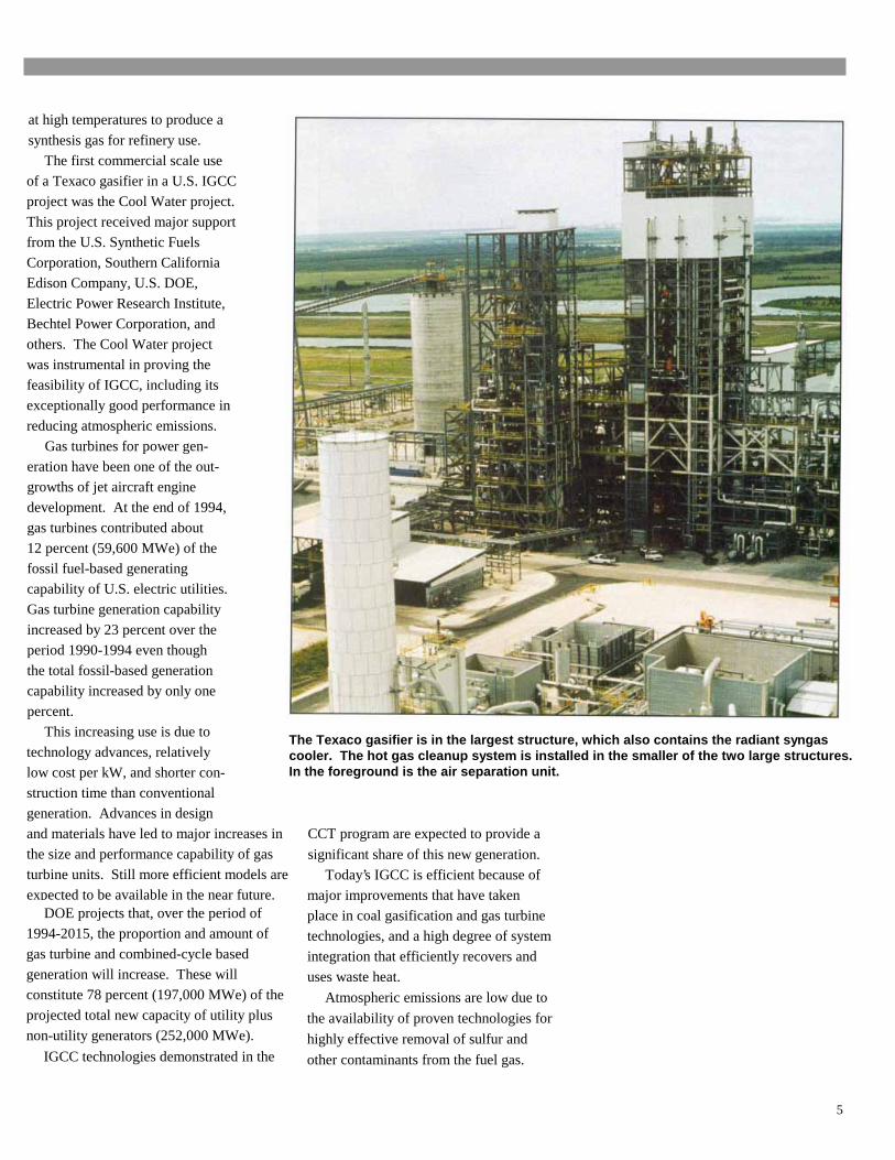
IGCC technologies demonstrated in the
The Texaco gasifier is in the largest structure, which also contains the radiant syngascooler. The hot gas cleanup system is installed in the smaller of the two large structures.In the foreground is the air separation unit.
CCT program are expected to provide a
significant share of this new generation.
Today’s IGCC is efficient because of
major improvements that have taken
place in coal gasification and gas turbine
technologies, and a high degree of system
integration that efficiently recovers and
uses waste heat.
Atmospheric emissions are low due to
the availability of proven technologies for
highly effective removal of sulfur and
other contaminants from the fuel gas.
5
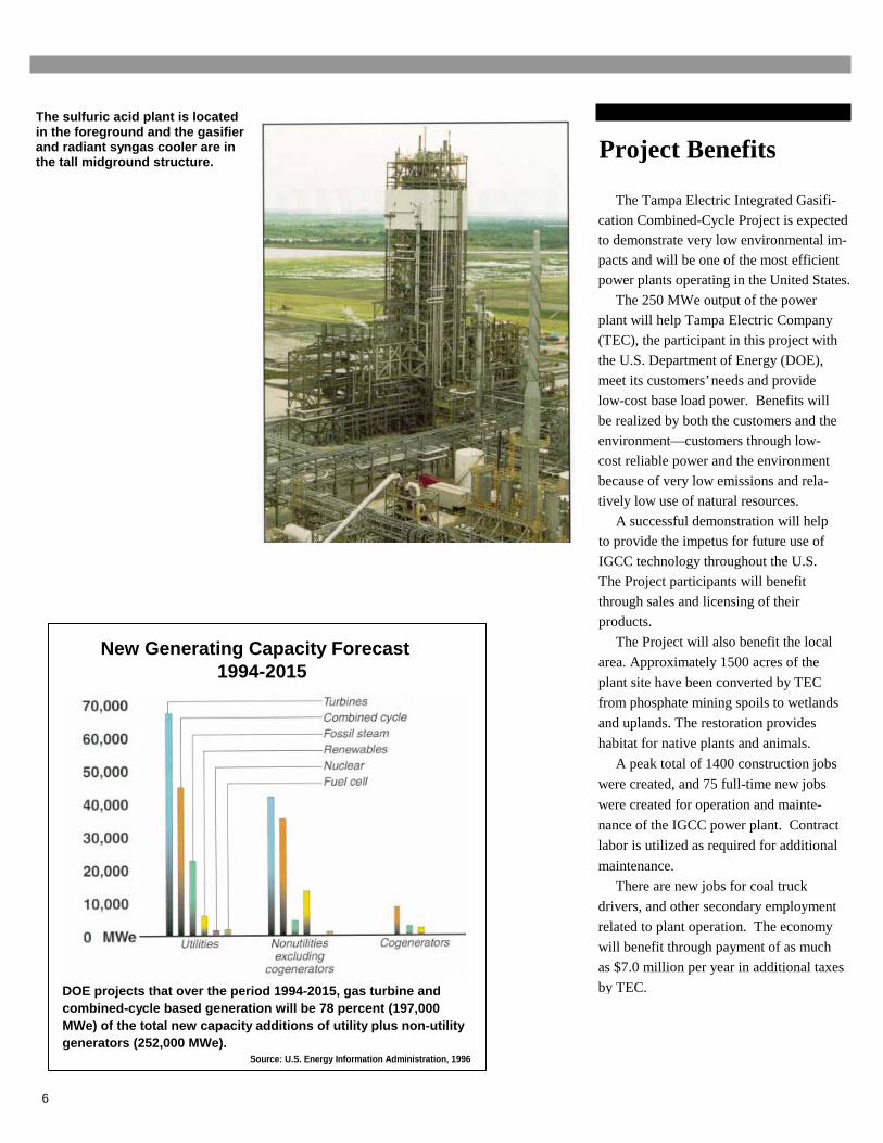
The sulfuric acid plant is locatedin the foreground and the gasifierand radiant syngas cooler are inthe tall midground structure.
New Generating Capacity Forecast1994-2015
DOE projects that over the period 1994-2015, gas turbine andcombined-cycle based generation will be 78 percent (197,000MWe) of the total new capacity additions of utility plus non-utilitygenerators (252,000 MWe).
Source: U.S. Energy Information Administration, 1996
6
Project Benefits
The Tampa Electric Integrated Gasifi-cation Combined-Cycle Project is expectedto demonstrate very low environmental im-pacts and will be one of the most efficientpower plants operating in the United States.
The 250 MWe output of the power
plant will help Tampa Electric Company
(TEC), the participant in this project with
the U.S. Department of Energy (DOE),
meet its customers’ needs and provide
low-cost base load power. Benefits will
be realized by both the customers and the
environment—customers through low-
cost reliable power and the environment
because of very low emissions and rela-
tively low use of natural resources.
A successful demonstration will help
to provide the impetus for future use of
IGCC technology throughout the U.S.
The Project participants will benefit
through sales and licensing of their
products.
The Project will also benefit the local
area. Approximately 1500 acres of the
plant site have been converted by TEC
from phosphate mining spoils to wetlands
and uplands. The restoration provides
habitat for native plants and animals.
A peak total of 1400 construction jobs
were created, and 75 full-time new jobs
were created for operation and mainte-
nance of the IGCC power plant. Contract
labor is utilized as required for additional
maintenance.
There are new jobs for coal truck
drivers, and other secondary employment
related to plant operation. The economy
will benefit through payment of as much
as $7.0 million per year in additional taxes
by TEC.

Project Description IGCC Inputs and Outputs
Project Participant Inputs Quantity, tons/day
TEC is an investor owned electric utility
headquartered in Tampa, Florida. It is the
principal wholly owned subsidiary of
TECO Energy, Inc., an energy related
holding company heavily involved in coaltransportation and power generation.
TEC presently has about 3400 MWe
of generating capacity, about 99 percent
from coal-fired units. TEC serves an area
of about 2000 square miles in west central
Florida. TECO Power Services (TPS), an-
other subsidiary of TECO Energy, oper-
ates a 295 MWe natural gas fired com-
bined cycle power plant in Florida, with
the electric power being sold under long-
term power sales agreements.
TPS developed the Project and has been
performing project management
throughout. Under terms of the
Cooperative Agreement TPS plans to
commercialize the Project IGCC
Major Participants
TEC has selected major technology
suppliers for this project that are experi-
enced and successful in their respective
industries. They include Texaco Develop-
ment Corporation, as the licensor of the
coal gasification technology and related
services; Bechtel Power Corporation, for
detailed engineering, procurement, start-
up and construction management; General
Electric, as the supplier of combined cycle
equipment; and GE Environmental
Services, Inc., designer of the hot-gas
cleanup system.
Site Description
The Project is Unit I of the new PolkPower Plant, located in south central Polk
Coal 2000Oxygen 1974Slurry water (recycled) 884Nitrogen to gas turbine 6024
Solids Output
Slag/fines from dewatering pit 311
Dry solids from brine concentrator 2.8
98% Sulfuric Acid 218
Net Electrical Output 250 MWe
Major ParticipantsOwner/operator
Project management and commercialization
Licensor of gasification technology
Supplier of gas turbine/combinedcycle equipment
Tampa Electric Company
TECO Power Services Corporation
Texaco Development Corporation
General Electric Corporation
GE Environmental Services, Inc.
Bechtel Power Corporation
MAN Gutehoffnüngshutte AG
L. & C. Steinmbller Gmbh
Air Products & Chemicals, Inc.
Monsanto Enviro-Chem Systems, Inc.
H.B. Zachry Company
The Industrial Company
Johnson Brothers Corporation
Aqua-Chem, Inc.
Davenport MammoetHeavy Transport
Designer of hot-gas cleanup system
Detailed engineering/constructionmanagement services, procurement,and startup
Supplier of radiant syngas cooling system
Supplier of convective syngas cooling system
Turnkey supplier for air separation unit
Turnkey supplier for sulfuric acid plant
Power block construction
Gasification area construction
Site development and civil contractor
Supplier of brine concentration plant
Transportation/erection of radiantsyngas cooler
7

A single Texaco gasifier processes 2000 tons per day of coal at about2500-2700°F (1371°-1482°C) to produce a raw syngas and molten slag. Thegas flows downward into the radiant syngas cooler where it is partly cooledand high pressure steam for power generation is produced. Slag is col-lected in a water pool at the bottom of the radiant syngas cooler and removed.
8
County, central Florida. The 4348 acre
site is located about 45 miles southeast
of Tampa and 17 miles south of Lake-
land in the heart of central Florida’s
phosphate mining region.
The Polk site is on a tract of land that
was previously mined for phosphate rock
and has been redeveloped and revege-
tated by TEC for this project.
The site area is predominantly rural.
Polk County is an important citrus-raising
and phosphate mining center, each being
important Florida industries.
About a third of the site is used for
power generation facilites. Another third
is used to enhance the environment by
creation of public fishing lakes for the
Florida Fish and Game Commission. Trans-
fer of these 1511 acres is expected to take
place before April 1997. The final third of
the site is primarily for access and providing
a visual buffer.
The site contains an 850 acre cooling
reservoir. State Highway 37 crosses the site
about one mile from the IGCC power plant.
Power Plant Description
The Project is demonstrating advanced
IGCC technology for production of 250 MWe
in a commercial, electric utility environment
on a greenfield site. It is demonstrating the
integrated performance of a Texaco gasifier,
metal oxide hot-gas cleanup system, con-
ventional cold-gas cleanup, and an ad-
vanced gas turbine with nitrogen injection
(from the air separation plant) for power
augmentation and NOX control.Makeup water for the power plant is
provided from on-site wells. All processwater is recycled.
Texaco gasifier
Coal is delivered to the site by truck
from a transloading facility at TEC’s Big
Bend Station in Apollo Beach, Florida.
Once on site, the coal is conveyed from
coal silos and fed to the grinding mill

with recycled process water and makeupwater from on-site wells.
The project gasifies about 2000 tons
per day of coal in a single gasifier. The
Texaco gasifier has been commercially
proven in several applications and the
scaleup, of less than a factor of two, to
this throughput is not considered to pose
a high level of risk.
Coal is slurried in water, and reacted
in the gasifier with 95 percent pure oxy-
gen (from the air separation unit) to pro-
duce a high temperature, high pressure,
medium-Btu synthesis gas, also known as
syngas.
The raw syngas is partly cooled by a
high temperature radiant heat recovery
unit prior to subsequent cooling stages.
Molten coal ash flows from the bottom of
the radiant syngas cooler into a water-filled
quench chamber where it solidifies into a
marketable slag by-product. The slag has
been found by the U.S. Environmental Pro-
tection Agency (EPA) to be non-leaching.
After additional cooling of the raw syn-
gas stream in parallel convective heat ex-
changers the stream is split into streams for
both hot- and cold-gas cleanup to remove
sulfur compounds and other contaminants.
Cold-gas cleanup
Cold-gas clean-up is the primary
method because the specific technologies
utilized are proven effective, reliable and
commercially available.
Ninety percent of the syngas is cleaned
by the cold-gas cleanup, but the system is
designed to accommodate the full produc-
tion of syngas if performance of the hot-
gas cleanup system is unacceptable.
Typical Coal Analysis(Pittsburgh No. 8 Seam)
Ultimate Analysis As-Received, wt%
9
Moisture 4.74
Carbon 73.76
Hydrogen 4.72
Nitrogen 1.39
Chlorine 0.10
Sulfur 2.45
Ash 7.88
Oxygen 4.96
Total 100.0
As-Received Higher Heating Value, Btu/Ib 13,290
The raw hot syngas is cooled to 100°F
for cold-gas cleanup by conventional acid
gas removal technology. This portion of
the plant is based upon absorption of H2S
by a liquid amine compound and is capable
of processing 100 percent of the syngas
produced by the gasifier. Steam stripping
removes the absorbed H2S which then
flows to the sulfuric acid plant.
Hot-gas cleanup
The potential advantage of hot-gas
cleanup is that it increases overall power
plant thermal efficiency because energy
losses in cooling the syngas to near ambient
temperature (used for cold-gas cleanup) are
eliminated. Costs are reduced compared to
cold-gas cleanup because less gas cooling
and other process equipment is needed.
To evaluate these potential benefits,
TEC included hot-gas cleanup to clean
10 percent of the syngas. GE Environ-
mental Services' advanced intermittently
moving bed hot-gas cleanup system is
utilized. This technology and the sorbents
used show important promise but are not
yet proven in commercial operation.
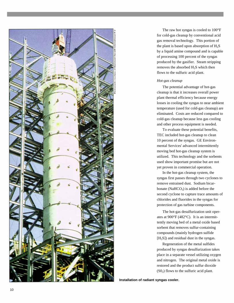
In the hot-gas cleanup system, the
syngas first passes through two cyclones to
remove entrained dust. Sodium bicar-
bonate (NaHCO3) is added before the
second cyclone to capture trace amounts of
chlorides and fluorides in the syngas for
protection of gas turbine components.
The hot-gas desulfurization unit oper-ates at 900°F (482°C). It is an intermit-tently moving bed of a metal oxide basedsorbent that removes sulfur-containingcompounds (mainly hydrogen sulfide[H2S]) and residual dust in the syngas.
Regeneration of the metal sulfides
produced by syngas desulfurization takes
place in a separate vessel utilizing oxygen
and nitrogen. The original metal oxide is
restored and the product sulfur dioxide
(S02) flows to the sulfuric acid plant.
Installation of radiant syngas cooler.
10
This is the first unit to demonstrateadvanced moving bed metal oxide hot-gas desulfurization technology on acommercial scale.
Power island
Combined, the cleaned syngas streamshave a heating value of about 265 Btu perstandard cubic foot (higher heating valuebasis). It is sent to the advanced GeneralElectric model MS 7001F gas turbine ofthe combined cycle power island where itis burned. About 192 MWe of electricpower is produced. The pressure of thegasifier was selected to match the inletpressure requirement of the gas turbine.
Nitrogen from the air separation unit (at98 percent purity) is mixed with the syngasat the gas turbine combustor to give thefollowing benefits to the power plant: (1)the enhanced mass flow through the gasturbine produces more power than withoutthe nitrogen; (2) the overall efficiency ofthe system is enhanced; and (3) low levelsof NOX emissions are obtained.
Hot exhaust from the gas turbine unitpasses through a heat recovery steamgenerator (HRSG) where three pressurelevels of steam are produced. The majorityof the steam is at high pressure and, withhigh pressure steam produced in thegasification stage, drives a reheat steamturbine-generator to produce about 121MWe. Flue gas exits through a 150 footstack. A flare is provided to dispose ofsyngas produced during startup, shutdown,and during transient operations.
Power consumption within thefacility is 63 MWe, resulting in a netpower output of 250 MWe.
The net power plant heat rate is animpressive 8600 Btu/kWh (about 40 per-cent efficiency), higher heating value ba-sis. A 230 kV, five-mile transmission lineconnects the power plant to the TEC grid.
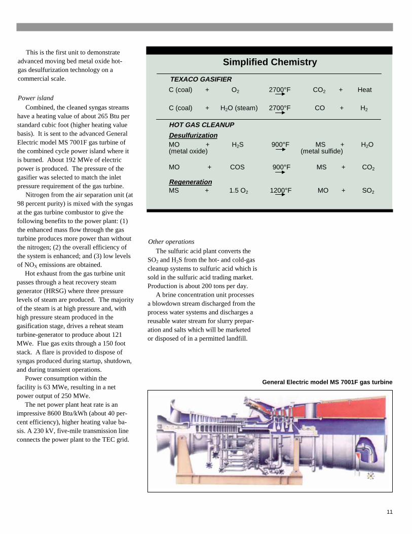
Simplified Chemistry
TEXACO GASIFIER
C (coal) + O2 2700°F CO2 + Heat
C (coal) + H2O (steam) 2700°F CO + H2
HOT GAS CLEANUP
DesulfurizationMO + H2S 900°F MS + H2O(metal oxide) (metal sulfide)
MO + COS 900°F MS + CO2
RegenerationMS + 1.5 O2 1200°F MO + SO2
Other operations
The sulfuric acid plant converts theSO2 and H2S from the hot- and cold-gascleanup systems to sulfuric acid which issold in the sulfuric acid trading market.Production is about 200 tons per day.
A brine concentration unit processesa blowdown stream discharged from theprocess water systems and discharges areusable water stream for slurry prepar-ation and salts which will be marketedor disposed of in a permitted landfill.
General Electric model MS 7001F gas turbine
11

Cleaned Syngas CompositionDelivered to Gas Turbine, Volume %
Constituent Hot-Gas Cleanup Cold-Gas Cleanup
Carbon monoxide
Hydrogen
Carbon dioxide
Methane
Water
Nitrogen
Argon
Hydrogen sulfide
Carbonyl sulfide
Ammonia
35.6
27.0
12.6
0.1
18.6
5.8
0.0
94.0 ppmv
0.0
0.1 ppmv
48.3
33.8
10.0
0.2
0.5
6.1
1.1
8.4 ppmv
127.0 ppmv
0.0 ppmv
About 10 percent of the syngas is cleaned by hot-gas cleanupand up to 100 percent by cold-gas cleanup.
General Electric Intermittent Moving Bed Hot Gas Desulfurization System.
12
Process Description
Texaco Gasification
Texaco coal gasification technology uses
a single-stage, downward-firing, entrained-
flow coal gasifier in which a coal/water slurry
(60-70 percent coal) and 95 percent pure
oxygen are fed to a hot gasifier. At a tempera-
ture of about 2700°F (1482°C), the coal re-
acts with oxygen to produce raw fuel gas
(syngas) and molten ash.
The hot gas flows downward into a radiant
syngas cooler where high pressure steam is
produced. The syngas passes over the sur-
face of a pool of water at the bottom of the
radiant syngas cooler and exits the vessel.
The slag drops into the water pool and is fed
from the radiant syngas cooler sump to a
lockhopper.The radiant syngas cooler is about
17 feet in diameter, 100 feet long, and weighs
about 900 tons. The "black" water flowing out
with the slag is separated and recycled after
processing in the dewatering system.
Gas Cleanup
Gas cleanup equipment in an IGCC power
plant is relatively inexpensive compared to flue
gas cleanup in a conventional coal-steam
power plant. Smaller equipment is required
because a much smaller volume of gas is
cleaned.
The gas volume is smaller because con-
taminants are removed from the pressurized
fuel gas before combustion. In contrast, the
volume of flue gas from a coal-steam power
plant is 40–60 times greater because the flue
gas is cleaned at atmospheric pressure.
Cold-Gas Cleanup
The raw syngas exiting the radiant syn-
gas cooler is first sent to parallel convective
syngas coolers. Ninety percent of the syngas
flows to the cold-gas cleanup system where
it is first treated in water scrubbers for re-
moval of entrained solids and the gas then
flows to the low temperature syngas cooling

system. The scrubber bottoms are routed to
the "black" water handling system where the
solids are separated. The effluent is
concentrated and crystallized as a solid form
that is shipped off-site either for reuse or
disposal in a permitted landfill. The sepa-
rated water is recycled for slurry coal feed.
The particulate-free gas is water-washed
to remove contaminants that would degrade
the sorbent in the absorber. The wash water
is sent to the ammonia stripper. The washed
syngas flows to the amine absorber where
the H2S and some of the CO2 (acid gases)
are absorbed. The "rich" amine is stripped of
acid gas in the stripper. The amine is re-
cycled and the separated acid gas is routed
to the sulfuric acid plant.
The cold-gas cleanup system is designed
to accept 100 percent of the raw syngas.
Hot-Gas Cleanup
This unit is designed to handle 10 percent
of the hot, raw syngas. Entrained fine par-
ticles in the hot syngas are removed in the
primary cyclone and sent to the "black"
water handling system. The exiting gas is
injected with sodium bicarbonate and then
enters a secondary cyclone where halogen
compounds (primarily chlorides and fluo-
rides) in the gas are chemically absorbed.
Halogens are removed to minimize corro-
sion of the gas turbine. Solids collected from
the second cyclone are sent off-site for
disposal in a permitted landfill and the gas
flows to the absorber.
A large fraction of any remaining particu-
late matter entering the absorber is captured
by the bed of mixed metal oxide sorbent.
The absorber is an intermittently moving
bed reactor. Syngas, containing H2S and
carbonyl sulfide (COS), enters the bottom of
the absorber and flows countercurrent to the
moving bed of sorbent pellets. The sulfur
compounds react with sorbent to form metal
sulfides. Syngas exiting the absorber is
expected to contain a maximum of 30 parts
per million of H2S and COS.
Regeneration of the spent sorbent is
important to avoid excessive sorbent
replacement costs. In this part of the hot
gas cleanup process the sulfide is con-
verted back to the oxide.
Sulfided sorbent is fed from the absorber
lockhopper to the top of the regenerator
where oxidation occurs. The sorbent moves
down the regenerator in concurrent flow with
the regeneration gas.
Temperature control is important to pre-
vent damage to the sorbent structure at
temperatures that are too high. Conversion
of metal sulfide to the inactive sulfate occurs
at temperatures that are too low.
The final regeneration step occurs at the
lower stage of the regenerator where nitro-
gen flows countercurrent to the sorbent. This
stream cools the sorbent, purges the
SO2-rich off gas and ensures complete
regeneration without sulfate formation
Recycled regenerator effluent gas is
used as a diluent for air to control the
temperature by means of a heat exchanger
in the loop. Steam is generated and utilized
in the combined cycle unit. A small amount
of sorbent fines is entrained in the gas
stream and collected in a high efficiency
barrier filter that removes fines larger than
five microns (99.5 percent removal of par-
ticulates). Collected solids are sent offsite
for disposal.
Larger sorbent particles entrained in the
gas stream are collected on screens at the
regenerator sorbent outlet; fugitive fines from
the screens are collected in a small
baghouse.
Combined CyclePower Generation
The gas turbine is a General Electric
model MS 7001F, designed for low-NOX
emissions when firing sygnas and with low
sulfur fuel oil that is used for startup and
backup. Rated output from the hydrogen
cooled generator on syngas is 192 MWe.
The gas turbine is an advanced turbine that
has been proven in a utility environment.
Nitrogen is used as a syngas diluent to
reduce NOX formation and also to increase
mass flow, resulting in a higher gas turbine
power output.
The HRSG is a three-pressure design
with natural circulation and reheat. The
steam turbine is a double flow reheat unit
with low pressure extraction. Nominal steam
inlet conditions are 1450 psig and 1000°F
with 1000°F reheat temperature. Expected
generator output during normal operation
is 121 MWe.
Air Separation Unit
The air separation unit provides 95
percent pure oxygen for the gasifier
operation, and warmed compressed
nitrogen for the gas turbine. Low pressure
95 percent oxygen is also supplied to the
sulfuric acid plant.
Sulfuric Acid Plant
In the sulfuric acid plant, the sulfur
containing gases from the hot- and cold-gas
cleanup systems are converted to 98
percent sulfuric acid for sale to the local
Florida fertilizer industry. The H2S from the
cold-gas cleanup unit is combusted to SO2
and mixed with hot gases containing SO2
from the hot-gas cleanup unit. The combus-
tion product gas stream, which also con-
tains sulfur trioxide (S03) and sulfuric acid
(H2SO4), is cooled.
The gas is converted to 98 percent
H2SO4 (about 200 tons per day are pro-
duced) after passing through three catalyst
beds charged with vanadium pentoxide
catalyst. Oxygen is utilized for conversion of
SO2 to SO3 in the process. After separa-
tion of H2SO4, the concentration of SO2
remaining in the gas stream is low enough
to permit direct discharge to the atmo-
sphere through a 200 foot stack.
13
EnvironmentalConsiderations
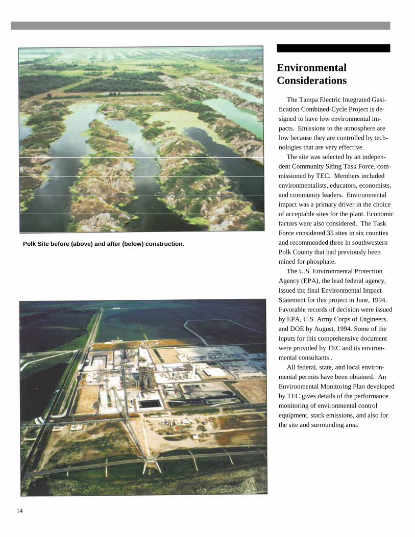
Polk Site before (above) and after (below) construction.
The Tampa Electric Integrated Gasi-
fication Combined-Cycle Project is de-
signed to have low environmental im-
pacts. Emissions to the atmosphere are
low because they are controlled by tech-
nologies that are very effective.
The site was selected by an indepen-
dent Community Siting Task Force, com-
missioned by TEC. Members included
environmentalists, educators, economists,
and community leaders. Environmental
impact was a primary driver in the choice
of acceptable sites for the plant. Economic
factors were also considered. The Task
Force considered 35 sites in six counties
and recommended three in southwestern
Polk County that had previously been
mined for phosphate.
The U.S. Environmental Protection
Agency (EPA), the lead federal agency,
issued the final Environmental Impact
Statement for this project in June, 1994.
Favorable records of decision were issued
by EPA, U.S. Army Corps of Engineers,
and DOE by August, 1994. Some of the
inputs for this comprehensive document
were provided by TEC and its environ-
mental consultants .
All federal, state, and local environ-
mental permits have been obtained. An
Environmental Monitoring Plan developed
by TEC gives details of the performance
monitoring of environmental control
equipment, stack emissions, and also for
the site and surrounding area.
14

Costs/Schedule/DemonstrationMilestones
The estimated cost of the Tampa Electric
Integrated Gasification Combined-Cycle
Project including the operation and testing
phase is approximately $506 million. DOE
is providing about $142 million.
Work on the project was initiated with
the completion of an agreement between
TEC and DOE in July 1992. Site, environ-
mental and permitting, engineering, pro-
curement and construction activities were
completed since then. Groundbreaking
took place in November, 1994, and the
facility was released to operations in
October 1996.
The four-year demonstration program
began in October, 1996. Data are being
gathered on power plant performance,
including environmental performance.
Operation will be on four Eastern U.S.
bituminous coals. Data will be collected
involving systems performance and operat-
ing and maintenance costs. Information on
startup, shut down and ramp rates will be
gathered and evaluated. Behavior of the
gas cleanup systems will be established
and emissions monitored.
Selected StartupMilestones Achieved
• Initial roll of the steam turbine:
June,1996
• Sulfuric acid plant and gasifier
completion: June, 1996
• Completion of the hot-gas
cleanup system: July, 1996
• Start demonstration program:
October, 1996
Allowed Stack Emissions(at 15 percent excess oxygen)
Allowed Emissions, pounds/hour
Pollutant
SO2
NOX
CO
VOC
PIVI/PM-10
During FirstTwo Years of
Demonstration
518
664
99
3
17
After FirstTwo Years of
Demonstration
357
223
98
3
17
Power Output
Gas Turbine
Steam Turbine
192 MWe
121 MWe
Gross
Auxiliaries Power Use
313 MWe
63 MWe
Net Power Output 250 MWe
Gas turbine, model MS 7001F, during manufacture.
15

Gasifier Run Summary
Start Date Major Accomplishments
7/96 First production of syngas
8/96 Achieved steady state in process water system
8/96 First utilization of low temperature gas coolingsystem
9/96 Achieved 100% gasifier load, first syngas to gasturbine, and first production of brine crystals
9/96 First integration of steam drums
10/96 First run >100 hours, full load gas turbine andcombined cycle operation on syngas, and firstproduction of sulfuric acid.
Preliminary Results
All construction activities at the Polk
Power Plant have been completed. TEC
also completed the reclamation of wet-
lands on both sides of State Highway 37
that crosses the site.
The Project power plant entered the
demonstration phase in October 1996.
Operating on a Pittsburgh No. 8 bitumi-
nous coal, results achieved have been
positive and encouraging.
A 101.6 hour run of the lGCC system
was conducted in mid-October. Long
term stable operation and full capacity
were achieved. These are critical elements
of the demonstration since they are neces-
sary precursors to the conduct of accep-
tance tests for the coal-gas cleanup and
sulfuric acid plant systems downstreamof the gasifier.
Operating on syngas as well as distillate
fuel, the unit has achieved full load on the
combustion turbine and steam turbine. As
planned, the combustion turbine achieved
the design values of 192 MWe on syngas,
and 121 MWe from the steam turbine, for a
total output of 313 MWe. The nitrogen
injection system operated as expected.As of the end of October, 1996 the unit
was operated only in the cold-gas cleanupmode. Work continues on check-out of thehot-gas cleanup systems and equipment; asof the publication date sorbent was loadedand attrition testing underway.
The sulfuric acid plant is in theforeground and the combined-cycleunit is in the background. The largeblack object (left center) is the heatrecovery steam generator.
16

Controls tuning continues and when com-
pleted, performance testing of the IGCC sys-
tem and equipment will be conducted.
As a result of its solid operating experi-
ence in the test program, the combined
cycle unit has been made available for
operation on distillate fuel to help meet
TEC’s load on an as-needed basis.
By-product evaluation is in progress.
The brine concentration system has pro-
duced chloride crystals which will be
evaluated by potential purchasers for reuse.
The sulfuric acid plant has produced sulfuric
acid which will be sold through the sulfuric
acid trading market in Florida. The slag is
being evaluated by the purchaser to deter-
mine how it will be utilized.
Testing of the IGCC system is planned
to optimize operation, improve overall
cycle efficiency and achieve emission
targets. TEC will begin with parametric
testing of key subsystems, including the
hot-gas cleanup system. Four types of
coals will be used in accordance with the
demonstration test plan.
Dawn arrives over thereclaimed wetlands sur-rounding the TampaElectric Integrated Gasi-fication Combined-CycleProject
Future Developments
The achievements and knowledge
gained from the Tampa Electric Inte-
grated Gasification Combined-Cycle
Project demonstration are expected to
benefit future users of this technology.
Evaluation of advanced features of the
Project will determine their viability for
future commercial applications. Future
commercial offerings of the technology
would be expected to be lower in cost
and improved in performance.
DOE believes that future IGCC green-
field power plants, based upon mature and
improved technology, will cost in the
range of $1000-1350/kW (1995 basis).
Heat rate is expected to be in the range of
7000-7500 Btu/kWh (46-49 percent
efficiency), higher heating value basis.
Costs will be further reduced if an existing
steam turbine is repowered and existing
site infrastructure utilized.
17

The Clean Coal Technology Program
The Clean Coal Technology (CCT)
Program is a unique partnership be-
tween the federal government and in-
dustry that has as its primary goal the
successful introduction of new clean
coal utilization technologies into the
energy marketplace. With its roots in
the acid rain debate of the 1980s, the
program is on the verge of meeting its
early objective of broadening the
range of technological solutions avail-
able to eliminate acid rain concerns
associated with coal use. Moreover,
the program has evolved and has
been expanded to address the need
for new, high-efficiency power-gener-
ating technologies that will allow coal
to continue to be a fuel option well into
the 21st century.
Begun in 1985 and expanded in
1987 consistent with the recommenda-
tion of the U.S. and Canadian Special
Envoys on Acid Rain, the program has
been implemented through a series of
five nationwide competitive solicita-
tions. Each solicitation has been
associated with specific government
funding and program objectives. After
five solicitations, the CCT Program
comprises a total of 40 projects located
in 18 states with a capital investment
value of nearly $6.0 billion. DOE’s
share of the total project costs is about
$2.0 billion, or approximately 34 percent
of the total. The projects’ industrial
participants (i.e., the non-DOE partici-
pants) are providing the remainder-
nearly $4.0 billion.
Clean coal technologies being
demonstrated under the CCT Pro-
gram are establishing a technology
base that will enable the nation to
meet more stringent energy and
environmental goals. Most of the
demonstrations are being conducted
at commercial scale, in actual user
environments, and under circum-
stances typical of commercial
operations. These features allow
the potential of the technologies to
be evaluated in their intended com-
mercial applications. Each applica-
tion addresses one of the following
four market sectors:
• Advanced electric powergeneration
• Environmental control devices
• Coal processing for clean fuels
• Industrial applications
Given its programmatic success,
the CCT Program serves as a model
for other cooperative government/
industry programs aimed at intro-
ducing new technologies into the
commercial marketplace.
18
Contacts
Project Team Members
Tampa Electric CompanyU.S. Department of Energy
Donald E. PlessDirector, Advanced TechnologyTECO Power Services Corp.P.O. Box 111Tampa, FL 33601-0111(813) 228-1330(813) 228-1308 fax
George E. LynchPortfolio Manager forGasification Power SystemsU.S. Department of EnergyOffice of Coal & Power SystemsFE-221/27OCC
19901 Germantown RoadGermantown, MD 20874-1290
(301) 903-9434(301) 903-9438 faxgeorge.lynch @hq.doe.gov
Nelson F. RekosProject ManagerU.S. Department of EnergyFederal Energy Technology CenterP.O. Box 880Morgantown, WV 26507-0880(304) 285-4066(304) 285-4403 [email protected]
Charles M. ZehIGCC Product ManagerFederal Energy Technology CenterP.O Box 880Morgantown, WV 26507-0880(304) 285-4265(304) 285-4403 [email protected]
To be placed on the Department of Energy’s distribution list for future information on the Clean Coal TechnologyProgram and the demonstration projects it is financing or on other Fossil Energy programs, please contact:
Victor DerDirector, Office of Power SystemsU.S. DOE, Office of Fossil Energy
Washington, DC 20585(301) 903-2700
(301) 903-2713 [email protected]
This report is available on the Internetat www.lanl.gov/projects/cctc
19
Bibliography
Black, C.R., "Polk Status Update,"Twelfth EPRI Conference on Coal Gasi-
fication Power Plants (San Francisco CA),
October 1993.
Black, C.R., "Tampa Electric Company’s
Polk Power Station Construction Update,"
EPRI Conference on New Power Genera-
tion Technology (San Francisco CA), Oc-
tober 1995.
Energy Information Administration, Office
of Integrated Analysis and Forecasting,
"Annual Energy Outlook 1996 with Pro-
jections to 2015," pp. 29, 38, DOE/FE-
0346, January 1996.
"IGCC Takes a Bold Leap Forward,"
Power, pp. 81-84, April 1996.
Jenkins, S., "Tampa Electric Company
Polk Power Station IGCC Project,"
Twelfth Annual International Pittsburgh
Coal Conference (Pittsburgh PA),
September 1995.
Jenkins S.D., "Polk Power Station Syngas
Cooling System," Eleventh Worldwide
Texaco Gasification Licensee Symposium
(White Plains NY), October 1994.
Jenkins, S.D., "Polk Status Update," Eco-
nomics of Emerging Clean Coal Technolo-
gies III, February 1994.
Pless, D.E., "Polk Status Update," U.S.DOE Third Annual Clean Coal Tech-
nology Conference (Chicago IL), Septem-
ber 1994
20
Pless, D.E., "Status Update, Polk Power
Station" U.S. DOE Fourth Annual Clean
Coal Technology Conference (Denver CO),
September 1995.
Pritchard, P.A. and Starheim, G.J.,"Turbine Developments for IGCC Applica-
tions, Status Update," Thirteenth EPRIConference on Coal Gasification PowerPlants (San Francisco CA), October 1994.
Stambler, I., "Progress in IGCC and
Advanced Cycles Outlined at EPRI Meet-
ing," Gas Turbine World, pp. 16-23,
January-February 1996.
Swanekamp, R., "Startup of Large-ScaleProjects Casts Spotlight on IGCC," Power,
pp. 59-68, June 1996.
Tampa Electric Company, "Integrated
Gasification Combined Cycle (IGCC)
Demonstration Project, Polk Power
Station Unit No. 1," Annual Report,
October 1993-September 1994, May 1995.
Tampa Electric Company, "Tampa ElectricCompany Polk Power Station Unit No. 1,"Annual Report, January-December 1992,October 1992.
Tampa Electric Company, "Tampa Electric
Company Polk Power Station Unit No. 1,"
Annual Report, January-December 1993.August 1993.
Tampa Electric Company, "Tampa ElectricCompany Polk Power Station Unit
No. 1," Preliminary Public Design Report,
June 1994.
Tampa Electric Company, "Volume ofEnvironmental Information, Tampa Elec-tric Company Polk Power Station," (Sub-mitted to) U.S. Department of Energy,1992.
U.S. Department of Energy, "Clean
Coal Technology Demonstration Pro-
gram—Program Update 1995:" pp. 6-3, 7-
26, 7-27; DOE/EIA-0383(96), April 1996.
U.S. Department of Energy, "IntegratedGasification Combined Cycle," Brochure,Morgantown Energy Technology Center,1993.
U.S. Environmental Protection Agency,
"Final Environmental Impact Statement,
Tampa Electric Company-Polk Power
Station," EPA 904/9-94-002(b), June 1994.

List of Acronyms and Abbreviations
Btu .............................................................................................British thermal unit
CCT ....................................................................................Clean Coal Technology
DOE ............................................................................. U.S. Department of Energy
EPA ........................................................... U.S. Environmental Protection Agency
HRSG .......................................................................heat recovery steam generator
IGCC .......................................................... integrated gasification combined cycle
kV .................................................................................................................kilovolt
kWh .....................................................................................................kilowatt hour
MWe ............................................................................................megawatt electric
ppmvd ................................................................... parts per million by volume, dry
TEC .................................................................................Tampa Electric Company
TPS .................................................................. TECO Power Services Corporation
PM ................................................................................................particulate matter
PM-10 ..............................particulate matter less than 10 micrometers in diameter
VOC .............................................................................volatile organic compounds
21