the swallow's anatomy · the swallow's anatomy the me 262, ... eight-stage axial-flow gas...
TRANSCRIPT

consTRUCTion
M e 2 6 2 i e a v e s t h e p r o d u c t i o n ( ine a t a h e a v j l y a s s e m b l y p i a n t s i t u a t e d i n t h e w o o d s , p o s s i b l y
e i m , a d j a c e n t t o t h e M u n i c h — S t u t t g a r t A u t o b a h n .
The Swallow's Anatomy The me 262, unofficially named the Sclìwalbe, or swallow, mas optimised for simple and cheap construction. The type's structure is described by Dr RLFRED PRICE
A LTHOUGH THE BASIC Structure of the Me 262 airframe was essentially nothing new, the aircraft did
introduce a number of innovations in aircraft design, most notably the wing's thickness-to-chord ratio, which was kept low to provide high-speed aerodynamic efficiency. These notes describe a typical Me 262A.
Fuselage The fuselage was an ali-metal semi-monocoque structure of near-triangular section with rounded corners, the wing passing through the base. It was assembied in tour sections: the nose cone, which housed the guns and ammunition, the centre-section, which included the cockpit; the rear fuselage, and the tail section.
Wings The Me 262's wing structure comprised two low one-piece cantilever wings of ali-metal
structure with single l-section main-spars, with flush-riveted stressed skin fitted into recesses in the underside of the fuselage. The centre portions, between the fuselage and engine nacelles, had a sweptback leading edge and swept-forward trailing edge. The outer portions of the wings were tapered and sweptback, with square-cut tips. The sweepback at the wing leading edge was 18° 32'. The wings had detachable tips and full-span automatic leading-edge slats. Frise-type ailerons were fitted in two sections on each wing, Slotted flaps were mounted inboard of the ailerons and had maximum extension of 60° and a backward movement of Sin.
Tail Assembly The cantilever tailplane was mountec half-way up the fin with mass-balanced rudder and elevators. Trim-tabs were fitted to both elevators and a geared tab fitted to the rudder for trimming.
A B O V E T h e Rheìnmetall-Borsig M K 1 0 8 3 0 m m c a n n o n . A t e c h n i c i a n h o i d s o n e of t h e 3 3 0 g (11oz) h i g h - e x p l o s i v e r o u n d s . B E L O W A n M e 2 6 2 A - 1 a o f J G 7 w i t h 12 R4M 5 5 m m folding-fìn r o c i t e t s m o u n t e d o n a w o o d e n racle u n d e r t h e s t a r b o a r d w i n g .
64 Aeroplane, June 200^
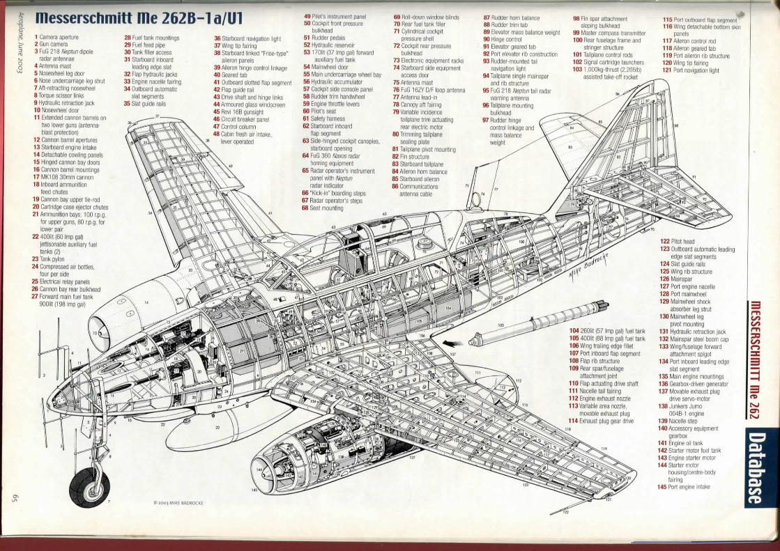
messerschmitt me 262B-1a/U1 1 Camera aperture 2 Sun camera 3FuG 2^S^eptund\^30\e
radar antenna e 4 Antenna masi 5 NosewheeI leg door 6 Nose undercarriage leg strut 7 AfI-retracting nosewheei 8 Torque scissor links 9 Hydraulic retraction jack 10 Nosewheel door 11 Extended cannon barrete on
two lower guns (antenna blasi proteclion)
12 Cannon barrel apertures 13 Starboard engine intake 14 Detachable cowling panels 15 Hinged cannon bay doors 16 Cannon barrel mountings 17MK108 30mm cannon 18 Inboard ammunition
feed chutes 19 Cannon bay upper tie-rod 20 CartrJdge case ejector chutes 21 Ammunition bays; 100 r.p.g,
for upper guns, 80 r.p.g. for lower pair
22 400lit (60 Imp gal) iettisonable auxiliary fuel tanks (21
23 Tank pylon 24 Compressed air botlles,
tour per side 25 Electrical relay panels 26 Cannon bay rear bulkbead 27 Forward main tuel tank
900lit (198 Imp gal)
28 Fuel tank mountings 29 Fuel feed pipe 30 Tank filler access 31 Starboard Inboard
leading edge siat 32 Flap hydraulic jacks 33 Engine nacelle fairing 34 Outboard automatic
siat segmenta 35 SIat guide rails
36 Starboard navigation llght 37 Wing tip fairing 38 Starboard linked "Frise-type"
aileron panels 39Aileron hinge control linkage 40 Geared tab 41 Outboard slotted flap segment 42 Flap guide rail 43 Drive Sbaft and hmge links 44 Armoured glass windscreen 45Revi 16Bgunsight 46 Circuit breaker panel 47 Control column 48 Cabin fresh air intake,
lever operated
49 Pilol's instrument panel 50 Cockpit front pressure
bulkbead 51 Rudder pedais 52 Hydraulic reservoir 53170lit(37 Imp gal) fonward
auxiliary fuel tank 64 (vlainwheei door 55 lylain undercarriage wbeei bay 56 Hydraulic accumulator 57 Cockpit side console panel 58 Rudder trim bandwbeei 59 Engine throttle levers 60 Pilot's seat 61 Safety harness 62 Starboard inboard
flap segment 63 Side-binged cockpit canopies,
starboard opening 64 FuG 360 Naxos radar
tioming equipment S6 Radar operator's insirument
panel with Neptun radar indicator
66 "Kick-in" boarding steps 67 Radar operator's steps
68 Roll-down window DIinds 70 Rear fuel tank filler 71 Cylindrical cockpit
pressure shell 72 Cockpit rear pressure
bulkbead 73 Electronic equipment racks 74 Starboard side equipment
access door 75 Antenna mast 76 FuG 16ZY D/F loop antenna 77 Antenna lead-in 78 Canopy aft fainng TOVariable incidence
tailplane trim actuating rear electric motor
80 Trimming tailplane sealing piate
81 Tailplane pivot mounting 82 Fin structure 83 Starboard tailplane 84 Aileron horn balance 85 Starboard aileron 86 Communications
antenna cable
87 Rudder horn balance 88 Rudder trim tab 89 Elevator mass balance welght 90 Hmge control 91 Elevator geared tab 92 Port elevator rib conslnjction 93 Rudder-mounted tail
navigation tight 94 Tailplane single mainspar
and rib structure 95 FuG 218 Neptun tail radar
warning antenna 96 Tailplane mounting
bulkbead 97 Rudder hinge
control linkage and mass balance weight
98 Fin spar attacttment sloping bulkbead
99 Master compass transmitter 100 Rear fuselage trame and
stringer structure 101 Tailplane control rods 102 Signal cartridge launchers 103 I.OOOkg-thrust (2,205lb)
assisted take-off rocket
115 Pori outDoard flap segment 116 wing detachable bottom skin
panels 117 Aileron control rod lIBAileron geared tab 119 Port aileron rib structure 120 Wing tip fairing 121 Port navigation light
122 Pitot head 123 Outboard automatic leading
edge siat segments 124 SIat guide rails 125 Wing rib structure 126 Ivlainspar 127 Port angine nacelle 128 Port mainwheei 129 MainwbeeI shock
absorber leg strut 130 Mainwheei leg
pivo! mounting 131 Hydraulic retraction jack 132 Mainspar steei boom cap 133 Wing/tuselage fonvard
attactiment spigot 134 Port inboard leading edge
siat segment 135 Main engine mountings 136 Geartìox-driven genetator 137 Movable exhaust ptug
drive servo-motor 138 Junkers Jumo
004B-1 angine 139 Nacelle Etep 140 Accessory equipment
gearbox 141 Engine oil tank 142 Starter motor fuel tank 143 Engine starter motor 144 Starter motor
housing/centre-body fairing
145 Port engine intake
consTRUCTion
Undercarriage This was of tricycle type witfi hydraulic retraction. Hydraulic brakes were used on ali wheels. The mainwheels retracted inwards into tfie underside of the wing centre section, and the nosewheel retracted rearwards into the fuselage,
Engines The most significant part of the Me 262's construction concerned the two Junkers Jumo 004 B-1 or B-4 eight-stage axial-flow gas turbine units, each deveioping 1,980lb thrust, mounted in a nacelle slung under each wing. The engines were started by means of a Riedel two-cylinder two-stroke starter motor built into the nose cone of each jet unit.
Both the main engines and their starter motors ran on J-2 fuel, 87-octane petrol mixed with 5 per cent diesel oil. The Me 262A-1a fighter carried four fuel tanks in the fuselage, two of 196 Imp gal, one of 38 gal and one of 132 gal capacity, There was also provision to carry two drop tanks under the forward fuselage, with a total capacity of 132 Imp gal.
Accommodation The pilot's cockpit was mounted over the wing trailing edge, and was protected by 15mm armour plates in front of and behind the pilot, and by a 90mm toughened glass windscreen, Access was gained via K1 a sideways-hinged canopy, am
me 262H-1ariahterdata
messerschmitt me 262 uariants Me 262A-0 Pre-production fighter version, 13 aircraft built during March and Aprii 1944. Most sent to test establishments
Me 262A-1a First production fighter version, armament four 30mm cannon. Morethan 1,000 built
Me 262A-1a/U3 Tactical reconnaissance version of the A-1 fighter. Armament reduced to one 30mm cannon, carried two Rb 50/30 aerial cameras in a vertical split pair. Built in small numbers
Me 262A-2a Fighter-bomber version of the A - l a fighter. Armour removed, and additional fuel tanks mounted in the rear fuselage. Racks for two 250kg or one 500kg bomb mounted under the nose. More than 100 built
Me 262B-1a Two-seat conversion trainer, fitted with dual controls. Second seat fitted to the rear of the first, in place of the rear fuselage fuel tank. Produced in small numbers
Me 262B-1a/U1 Two-seater modified for the nightfighter role, Fitted with SN-2 Liechtenstein, later Neptun, airborne interception radar. Also carried the Naxos equipment for homing on emissions from the British H^S radar. Produced in small numbers
Me 262 B-2a Definitive nightfighter variant. As the B-1a/U1, but with length increased by just under 4ft to accommodate a fuel tank in the rear fuselage. Produced in small numbers
Dimensions Span Length Height Wing area Wing loading at normal Ioaded weight
Weights Empty, equipped Normal Ioaded (no external stores)
Performance Max speed {clean)
41ft OMin (12-5m) 34ft 9;^in (10-6m) l l f t e X i n (3-5m) 233-58ft' (21-72m) 60-4lb/ft^
9,742lb (4,420kg) 14,101 Ib (6,396kg)
Max initial rate of climb Time to 19,500ft Range
513 m.p.h. at sea levei, 541 m.p.h. al 19,500fl, limiting safe Mach No 0-83 3,940ft/min 6min 48sec Normal fighter internai tankage, 300 miles at s/l, 650 miies at 29,500ft
Armament Fighter Four 30mm Rheinmetall-Borsig MK108 cannon, 100 r.p.g. for the two upper weapons, 80 r.p.g. for the two lower. Later modified to carry 24 R4M unguided rockets on wing-mounted wooden racks Fighter-bomber Two 30mm MK108 cannon with 80 r.p.g. Two 250kg (550lb) or one 500kg (1,100lb) bombs carried externally under the nose Tactical reconnaissance version One 30mm cannon in the extreme nose. Two Rb 50/30 automatic cameras in vertical split pair
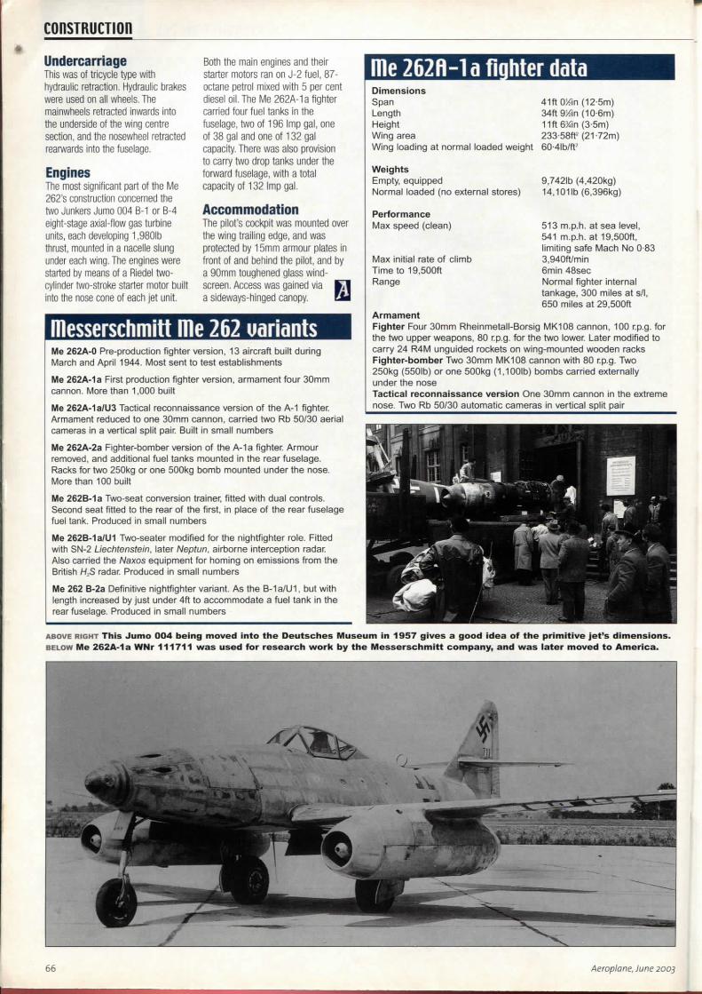
A B O V E R I G H T Th is J u m o 0 0 4 b e i n g m o v e d i n t o t h e D e u t s c h e s M u s e u m in 1 9 5 7 g i v e s a g o o d i d e a of t h e p r i m i t i v e j e t ' s d i m e n s i o n s . B E L O W Me 262A-1a WNr 1 1 1 7 1 1 w a s u s e d f o r r e s e a r c h w o r k by t h e M e s s e r s c h m i t t c o m p a n y , a n d w a s l a t e r m o v e d t o A m e r i c a .
66 Aeroplane, June 200j
HEUI ERGinE - HEUI PROBLEmS messERSCHmin IHE 262 Database The radicai new Jumo 004 jet engines gaue the llle 262 outstanding performance -prouided they uiorhed properly. Dr ALFRED PRICE ejtplains tiow difficulties uiitli production greatly limited Its potential capability
Engine noubles A TTHE END 0FTHE 1930sit
was reaiised that the laws of physics dictated the maximum speed propeller-
driven fighters couid attain — somewhere around 500 m,p,fi. The problem centred on the inefficiency of tfie propeller as a means of converting the rotational power from a pislon engine into propulsive thrust. As an aircraft neared that speed, propeller efficiency fell drastically.
For high-speed flight, the gas turbine was more efficient than the piston engine. The Junkers Jumo 004 gas turbine, the unit which powered the Me 262 after spring 1942, developed 1,850!b of thrust and weighed 1,590lb, Like their counterparts in Great Britain, German engineers wod̂ ing on the eady gas turbine engines for aircraft were beguiied by their simplicity. There were no propeller conversion losses, no reciprocating parts, and thrust was more or less Constant throughout the speed range.
On the down side, however, the gas turbine ran at far higher temperatures, much greater rotational speeds, and proved considerably more difficult to control than previous types of aircraft engine. Designers of the earty gas turbines faced a host of new problems which, in many cases, they had to resolve from first principles.
German engineers working in this fìeid faced further constraints, By the mid-war period chromium and nickel, ttie Steel-hardening elements usually considered necessary for high-
temperature Steel alloys, were in desperately short supply in Germany, The munitions industry's needs exceeded supply and stockpiles of these matehais depleted with each month, There was iittìe to spare for the jet engine programmo, Those working on jet engines endeavoured to design around the problem, and performance carne secondary to building engines that couId be mass-produced using available matenals.
In the case of the Jumo 004, Junkers engineers used substitute matenals which were often not up to the job. The engine's combustion chambers, for example, were fashioned from mild steeI with a spray-coating of aluminium baked on to prevent oxidisation. During running, these gradually became distorted, thus limiting the lite of the engine.
Early production Jumo 004 B-1 engines had a running lite of only 10-12 hours. Pilots had to be very careful in handiing the throttles it they were to avoid the risk of engine failures, flameouts or engine fires, One of the most difficult problems concerned getting the correct tuel flow to the engine throughout the Me 262's performance envelope. Too much fuel and the turbine blades wouid burn out, too little and the engine wouId flame out- At altitudes above 13,000ft the engine became increasingly temperamental, and if it suffered a flameout it was necessary to descend below that altitude before attempting a relight. The short running lite, along with many other
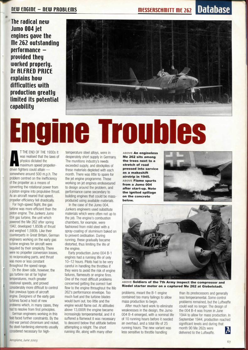
A B O V E A n e n g i n e l e s s M e 2 6 2 sìts a m o n g t h e t r e e s n e x t t o a s t r e t c h of r o a d p r e s s e d i n t o servìce as a m a k e s h i f t aìrstrip in 1945 . A B O V E F l a m e s p u r t s f r o m a J u m o 0 0 4 a f t e r s t a r t ' u p . N o t e t h e i g n i t e d s p i l l a g e o n t h e c o n c r e t e b e l o w .
A B O V E Soldìers o f t h e 7 t h A r m y ìnspect t h e c o m p r e s s o r a n d
Riede l s t a r t e r m o t o r o n a c a p t u r e d M e 2 6 2 a t G i e b e l s t a d t .
problems, meant the B-1 engine contained too many failings to allow mass production to begin.
After much hard work to eliminate weaknesses in the design, the Jumo 004 B-4 emerged, with a nominai lite of 10 running hours before it needed an overhaul, and a total lite of 25 running hours. The new vanant was less sensitive to throttle handiing
than Its predecessors and generally less temperamental. Some control problems remained, but the Luftwaffe couId wait no longer. The design of the 004 B-4 was frozen in June 1944 to allow for mass production. In September 1944, production reached significant levels and during that month 90 Me 262s were E l delivered to the Luftwaffe. EU
Aeroplane, June 2003 67
fIGHTEROR BOmBER?
In may1944, Hdolf Hitler ordered that the me 262 mas initially to go into action only in the high-speed bomher role. Despite uiide condemnation, there were sound reasons for adopting such a course. Dr ALFRED PRICE esamines the motiues for the order, and its effect
UNTILTHEAUTUMN 0F1943 the Me 262 had been considered solely for the bomber-destroyer role. By
then it was clear that the Aliies were assembling forces for a major invasion operation in the following year, to be launched against a point in nortfi-west Europe, When the blow fell, the tight to secure the beachhead wouId decide the outcome of the war If the invasion succeeded, the German Army wouId be squeezed inexorably between the Eastern and Western fronts. If, on the other band, the invasion was defeated, Allied losses woold probably be so great as to preclude a further attempi for some time, During that time the German Army couId concentrate its forces on the Eastern Front, and try to secure a major victory there.
The criticai initial hours of a landing operation wouId be fraught with difficulty and confusion. How much more difficult wouId the invaders' task be, if the Luftwaffe seni 50 or 100 high-speed bombers lo bomb and strale the troops coming ashore? Just a lew hours delay in securing the beachhead might be decisive, if German armoured units reached the scene first and drove the invaders into the sea. In the evenl, the landings on Ornato beach on D-Day ran into severe difficulties, and had there been additional harassment from scores of high-speed bombers strafing the troops as they came ashore, the landing couId bave faiied disastrously.
In November 1943 Hitler had watched an impressive demons-Iration of high-speed flight by the Me
262 V6. Willi Messerschmitt was in attendance, and aftemards the FiJhrer asked whelher the aircraft couId carry bombs. Messerschmitt assured him it couId, either one 1,000kg(2,200lb)or two 500kg (1,100lb) bombs. That was the answer Hitler wanted to bear. This was the "Blitzbomber" he sought, an aircraft with the speed to punch through the Allied tighter screens and plani its bombs on the invaders.
From then on, the Me 262 fighter-bomber fealured prominenlly in Hitler's counter-invasion plans. Yet he faiied to communicate the strength of his feelings to those responsible for preparing the aircraft for that role. Significantly, in the months that followed, the Messerschmitt company did not iniliale detaiied design work on a fighter-bomber version of the Me 262, and senior Luftwaffe officers
did not press it to do so. For his part Generalfeldmarschall Erhard Milch, in charge of aircraft production for the Lufhwaffe, acknowledged the usefulness of aircraft as a fighter-bomber But he considered that it wouId do better initially as a bomber-destroyer, and he concentrated the work on readying the Me 262 for service in that role, That divergence, between Hitler's wishes and the course of the aircrafl's development, set in motion a train of events that threatened to shake Ihe Me 262 programmo to its very foundations,
Matters came to a head on May 23,1944, when Hitler ordered a top levei conference at his Berghot residence to discuss Ihe latest Luftwaffe production programmes. Among those present were /?e/c/7smarsc/7a//Hermann Goering, Erhard Milch, Luftwaffe Chiet of Staff
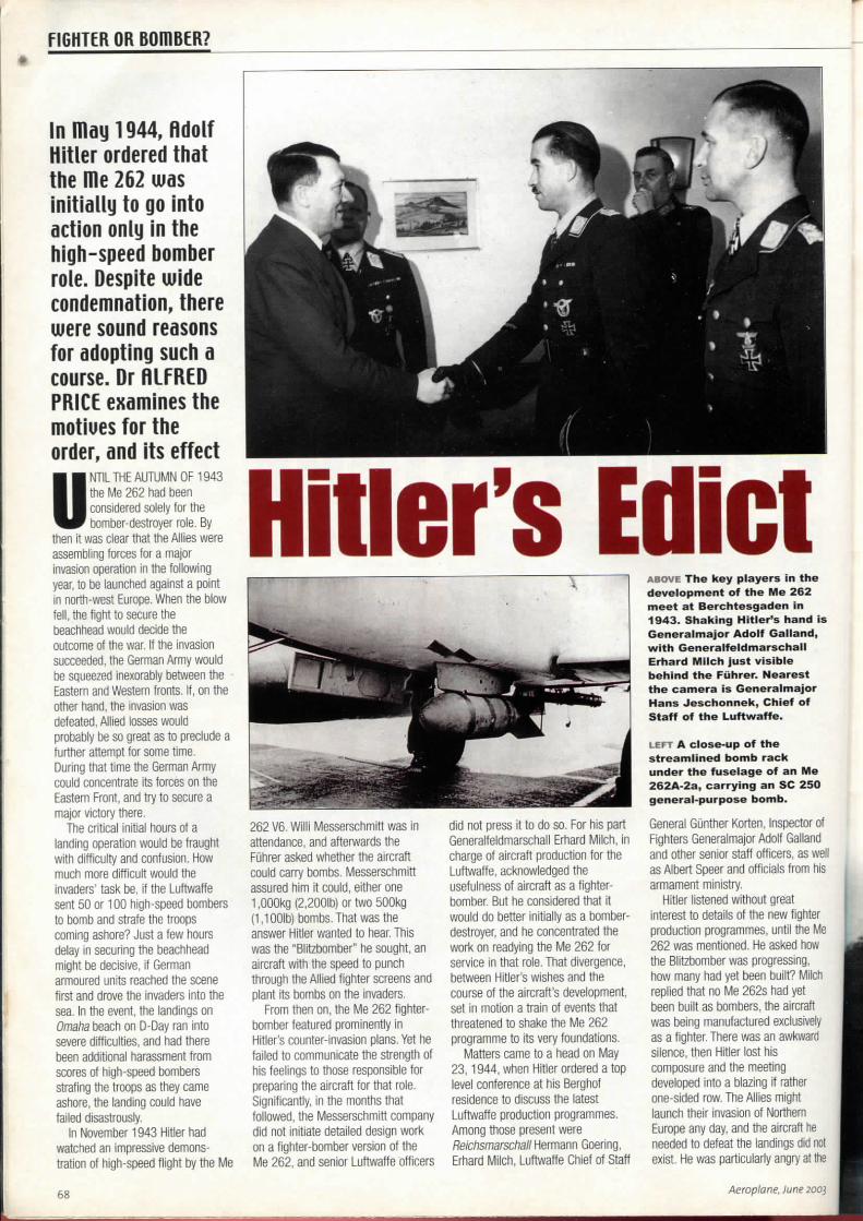
A B O V E T h e k e y p l a y e r s i n t h e d e v e l o p m e n t o f t h e Me 262 m e e t a t B e r c h t e s g a d e n in 1 9 4 3 . S h a k i n g H i t l e r ' s h a n d is G e n e r a l m a j o r A d o l f G a l l a n d , wìth G e n e r a l f e l d m a r s c h a l l E r h a r d M i l c h j u s t v i s i b l e b e h i n d t h e Fùhrer. N e a r e s t t h e c a m e r a is G e n e r a l m a j o r H a n s J e s c h o n n e k , Ch ie f of S t a f f o f t h e L u f t w a f f e .
L E F T A c l o s e - u p o f t h e streamlìned b o m b r a c k u n d e r t h e f u s e l a g e o f a n Me 2 6 2 A - 2 a , c a r r y i n g a n SC 2 5 0 g e n e r a l - p u r p o s e b o m b .
General Gùnther Korten, Inspector of Fighters Generalmajor Adolf Galland and other senior staff officers, as well as Albert Speer and officiais from his armament ministry.
Hitler listened without great interest to details of the new fighter production programmes, unhi the Me 262 was menlioned. He asked how the Blitzbomber was progressing, how many had yet been built? Milch replied that no Me 262s had yet been built as bombers, the aircraft was being manufactured exclusively as a fighter There was an awkward silence, then Hitler lost his composure and the meeting developed into a blazing if rather one-sided row. The Allies might launch their invasion of Northem Europe any day and the aircraft he needed lo defeal the landings did not exist. He was particulady angry al the
68 Aeroplane. June 2oos
mESSeRSCHIÌÌITT me 262 Database way he had been misied on tbe Me 262's ability to carry bombs.
Hitler then dismissed everyone excepi Goering, and delivered a blistering attack on the latter for his incompetence in mishandiing the matter. At the end of the audience, the Fuhrer declared that he now held Goehng personally responsible for seeing the Me 262 into service as a Blitzbomber as rapidly as possible, New aircraft coming off the production lines were to be delivered onlyto bomber units.
The conversion for the new role involved removing much of the armour piate, installing extra fuel tani<s and fitting streamlined bomb pylons under the fuselage. While these were not major modifications, they couid not easily be incorporated in aircraft aiready built, Instead, aircraft in the eady stages of assembly were selected for modification.
The first casualty of the row was Erhard Milch, for Hitler had lost confidence in the man he blamed for misleading him. In the weeks that followed, Milch was stnpped of his various offices. In retrospect, it is surpnsing that the Fùhrer did no more than that,
On June 6,1944, ten days after the tempestuous conference at Berchtesgaden, Allied troops blasted their way ashore in Normandy. By mid-morning, ali four of their beachheads were secure and no power at Adolf Hitler's command couId dislodge them. The opportunity for the Me 262 to play a decisive role against that operation, if it ever existed, had passed.
By D-Day fewer than 30 preproduction and production Me 262s had been delivered to the Luftwaffe, ali with temperamental engines. Clearly the aircraft was not yet ready tor action, Regardless of what Hitler, Milch, Goering or Messerschmitt had or had not dono, the factor limiting production of the Me 262 in any role
l was the failure to bnng the Jumo • 004 gas turbine to the point where it
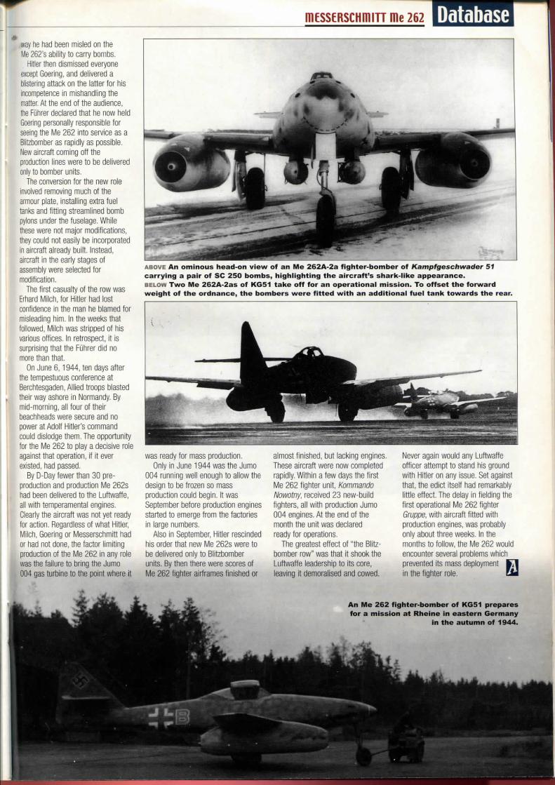
A B O V E A n omìnous h e a d - o n v i e w of a n Me 2 6 2 A - 2 a f i g h t e r - b o m b e r of KampfgBschwader 51 c a r r y i n g a p a i r o f SC 2 5 0 b o m b s , h i g h i i g h t i n g t h e a i r c r a f t ' s s h a r k - i i k e a p p e a r a n c e . B E L O W T w o M e 2 6 2 A - 2 a s o f K G 5 1 t a k e o f f f o r a n o p e r a t i o n a l m i s s i o n . To o f f s e t t h e f o r w a r d w e i g h t o f t h e o r d n a n c e , t h e b o m b e r s w e r e fìtted wìth a n a d d i t i o n a l f u e l t a n k t o w a r d s t h e rear.
was ready for mass production. Only in June 1944 was the Jumo
004 running well enough to allow the design to be frozen so mass production couId begin. It was September before productìon engines started to emerge from the factories in largo numbers,
Also in September, Hitler rescinded his arder that new Me 262s were to be delivered only to Blitzbomber units. By then there were scores of Me 262 fighter atrframes finished or
almost finished, but lacking engines. These aircraft were now completed rapidly, Within a few days the first Me 262 fighter unit, Kommando Nowotny, received 23 new-build fighters, ali with production Jumo 004 engines. At the end of the month the unit was declared ready for operations.
The greatest effect of "the Blitz-bomber row" was that it shook the Luftwaffe leadership to its core, ieaving it demoralised and cowed.
Never again wouId any Luftwaffe officer attempt to stand his ground with Hitler on any issue. Set against that, the edict itself had remarkably little effect. The delay in fielding the first operational Me 262 fighter Gruppe. with aircraft fitted with productìon engines, was probably only about three weeks. In the months to follow, the Me 262 wouId encounter several problems which prevented its mass deployment K1 in the tìghter role. lÉm
A n M e 2 6 2 f i g h t e r - b o m b e r o f KG51 p r e p a r e s f o r a m i s s i o n a t R h e i n e i n e a s t e r n G e r m a n y
i n t h e a u t u m n of 1944.